WO2017164047A1 - Screen device - Google Patents
Screen device Download PDFInfo
- Publication number
- WO2017164047A1 WO2017164047A1 PCT/JP2017/010558 JP2017010558W WO2017164047A1 WO 2017164047 A1 WO2017164047 A1 WO 2017164047A1 JP 2017010558 W JP2017010558 W JP 2017010558W WO 2017164047 A1 WO2017164047 A1 WO 2017164047A1
- Authority
- WO
- WIPO (PCT)
- Prior art keywords
- locking
- screen
- guide
- support rail
- edge
- Prior art date
Links
Images


Classifications
-
- E—FIXED CONSTRUCTIONS
- E06—DOORS, WINDOWS, SHUTTERS, OR ROLLER BLINDS IN GENERAL; LADDERS
- E06B—FIXED OR MOVABLE CLOSURES FOR OPENINGS IN BUILDINGS, VEHICLES, FENCES OR LIKE ENCLOSURES IN GENERAL, e.g. DOORS, WINDOWS, BLINDS, GATES
- E06B9/00—Screening or protective devices for wall or similar openings, with or without operating or securing mechanisms; Closures of similar construction
- E06B9/52—Devices affording protection against insects, e.g. fly screens; Mesh windows for other purposes
- E06B9/54—Roller fly screens
-
- E—FIXED CONSTRUCTIONS
- E06—DOORS, WINDOWS, SHUTTERS, OR ROLLER BLINDS IN GENERAL; LADDERS
- E06B—FIXED OR MOVABLE CLOSURES FOR OPENINGS IN BUILDINGS, VEHICLES, FENCES OR LIKE ENCLOSURES IN GENERAL, e.g. DOORS, WINDOWS, BLINDS, GATES
- E06B9/00—Screening or protective devices for wall or similar openings, with or without operating or securing mechanisms; Closures of similar construction
- E06B9/02—Shutters, movable grilles, or other safety closing devices, e.g. against burglary
-
- E—FIXED CONSTRUCTIONS
- E06—DOORS, WINDOWS, SHUTTERS, OR ROLLER BLINDS IN GENERAL; LADDERS
- E06B—FIXED OR MOVABLE CLOSURES FOR OPENINGS IN BUILDINGS, VEHICLES, FENCES OR LIKE ENCLOSURES IN GENERAL, e.g. DOORS, WINDOWS, BLINDS, GATES
- E06B9/00—Screening or protective devices for wall or similar openings, with or without operating or securing mechanisms; Closures of similar construction
- E06B9/56—Operating, guiding or securing devices or arrangements for roll-type closures; Spring drums; Tape drums; Counterweighting arrangements therefor
- E06B9/58—Guiding devices
-
- E—FIXED CONSTRUCTIONS
- E06—DOORS, WINDOWS, SHUTTERS, OR ROLLER BLINDS IN GENERAL; LADDERS
- E06B—FIXED OR MOVABLE CLOSURES FOR OPENINGS IN BUILDINGS, VEHICLES, FENCES OR LIKE ENCLOSURES IN GENERAL, e.g. DOORS, WINDOWS, BLINDS, GATES
- E06B9/00—Screening or protective devices for wall or similar openings, with or without operating or securing mechanisms; Closures of similar construction
- E06B9/52—Devices affording protection against insects, e.g. fly screens; Mesh windows for other purposes
- E06B9/54—Roller fly screens
- E06B2009/543—Horizontally moving screens
Definitions
- the present invention relates to a screen device attached to a building opening for light shielding, heat insulation, blindfolding, insect repellent, pollen invasion prevention and the like.
- a screen for shading, heat insulation, blindfolding, insect repellent, prevention of pollen entry, etc. is stretched in the screen frame to be installed in the opening of the building, and this screen can be moved laterally within the screen frame.
- Screen devices that open and close are known as disclosed in Patent Document 1, Patent Document 2, and the like.
- the screen device has screen guides that support upper and lower ends of the screen stretched on the screen frame.
- This screen guide is for preventing the screen from being greatly bent by the action force of wind or the like, and is formed by connecting a plurality of guide pieces in series and in a freely bendable manner at the end of the screen.
- the end of the screen is supported in a straight line by being arranged along the straight line.
- the screen guide 60 is installed horizontally on the lower side of the screen frame so that the screen 61 will not be displaced with the screen 61 when the screen 61 receives a lateral force.
- the rail 62 is supported by the rail 62 by fitting it into a concave groove 64 formed on the bottom surface of the guide piece 63.
- a pair of locking edges 62a and 62a projecting in the width direction are formed on the rail 62, and a pair of engagement edges are formed on the groove wall of the concave groove of the guide piece 63. It is desirable to form the pawls 64a and 64a and to lock the pawls 64a and 64a to the latching edges 62a and 62a.
- the screen guide as disclosed in FIG. 1 of Patent Document 1, is led into and out of the operation rod in accordance with the opening / closing operation of the screen (first type), and Patent Document As shown in FIG. 5 of FIG. 1, there is one (second type) that is led out into the left or right vertical frame ridge (fixed frame) of the screen frame.
- the configuration of the rail 62 and the guide piece 63 shown in FIG. 23 can be applied only to the second type screen guide among the two types of screen guides (see paragraph [0052] and FIG. 11c). This is because the distance between the pair of locking claws 64a, 64a of the guide piece 63 is smaller than the distance between the tip ends of the pair of locking edges 62a, 62a of the rail. 64a must be locked to the locking edges 62a and 62a from the end in the length direction of the rail 62, and cannot be locked to the locking edge at an intermediate position of the rail. It is.
- the rail 62 and the guide piece shown in FIG. 23 are also used in the first type of screen guide, that is, the type of screen guide that is pulled into or pulled out of the operating rod that moves along the rail. It is desired that 63 configurations can be applied.
- the technical problem of the present invention is to lock a screen guide that is pulled into or pulled out of the operating rod in accordance with the opening / closing operation of the screen by the operating rod at an intermediate position of the supporting rail. Or to be separated from the support rail.
- a screen device of the present invention includes a screen frame attached to an opening of a building, an operating rod that is disposed vertically in the screen frame and can be moved in the left-right direction, and the screen frame.
- a screen that is stretched between one of the left and right vertical frame ridges and the operation rod, and is disposed on at least one of a screen that opens and closes the screen frame by a movement operation of the operation rod, and upper and lower ends of the screen,
- a screen guide that is pulled out from or into the end of the screen by moving the operating rod, and the screen guide that is pulled out from the operating rod.
- Supporting rails linearly along the screen, the supporting rails having first locking edges projecting on both sides in the width direction of the supporting rails.
- the screen guide has a second locking edge
- the screen guide is formed by connecting a plurality of guide pieces so as to be bent in series and only in one direction, and the guide piece engages with an end of the screen.
- a locking member having a first locking portion and a second locking portion locked to the first locking edge and the second locking edge of the support rail, and the locking member A first position where the first locking portion and the second locking portion are locked to the first locking edge and the second locking edge of the support rail, respectively, and the first locking portion;
- the second locking portion are connected so as to be freely displaceable to a second position disengaged from the first locking edge and the second locking edge, respectively.
- the locking member has a concave support groove into which the support rail fits, and one of the pair of groove walls opposed to the support groove has the first locking wall. It is desirable that the second locking portion is formed on the other second groove wall while the portion is formed. More preferably, the first locking portion and the second locking portion have locking claws that protrude inward in the width direction of the support groove and are locked to the first locking edge and the second locking edge. And at least one surface of the inner surface of the locking claw and the back surface of the locking edge, and at least one surface of the outer surface of the locking claw and the surface of the locking edge is the locking claw. Or it is that it inclines in the direction where the thickness of this latching claw or a latching edge becomes thin gradually toward the front end side of a latching edge.
- the support groove when the screen guide is supported linearly along the support rail, the support groove is inclined and opposed to the support rail.
- a part of the first groove wall and the second groove wall are formed so as to be in contact with the first locking edge and the second locking edge, respectively, and a portion of the first groove wall that is in contact with the first locking edge
- the first locking portion is formed, and the second locking portion is formed at a portion of the second groove wall that contacts the second locking edge.
- the guide piece has a first end in the direction along the support rail and a second end opposite to the first end, and the first locking portion is either the first end side or the second end side.
- the second locking portion is formed on the other of the first end side and the second end side.
- the locking member of the guide piece is connected to the piece main body so as to be rotatable around an axis perpendicular to the guide piece, and is rotated in the forward and reverse directions. It can be configured to be displaced to the first position and the second position by movement.
- the locking member of the guide piece has a pair of movable part pieces that are displaceable in a direction in which the interval between them changes, and one and the other of the pair of movable part pieces One and the other of the first locking portion and the second locking portion may be formed.
- a screen support mechanism for supporting an end portion of the screen in a screen device in which the screen is stretched in a screen frame so as to be freely opened and closed.
- a supporting screen guide and a supporting rail for supporting the screen guide the supporting rail having a first locking edge and a second locking edge protruding on both sides in the width direction of the support rail;
- the screen guide is formed by connecting a plurality of guide pieces so that they can be bent in series and only in one direction, and the guide piece includes a piece main body that engages with an end of the screen, and a first piece of the support rail.
- a locking member having a first locking portion and a second locking portion that are locked to the first locking edge and the second locking edge.
- the guide piece forming the screen guide is constituted by the piece main body and the locking member, and the locking member includes the first locking portion and the second locking portion of the support rail. A first position for locking to the first locking edge and the second locking edge, and a second position where the first locking portion and the second locking portion are disengaged from the first locking edge and the second locking edge, respectively. Therefore, the guide piece, that is, the screen guide, can be engaged with or separated from the support rail at an intermediate position of the support rail.
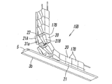
- FIG. 2 is a partial perspective view of FIG. 1. It is the perspective view which isolate
- FIG. 7 is a bottom view of FIG. 6. It is a front view of a guide piece and a rail. (A) is a bottom view when the locking member of the guide piece is in the first position, and (b) is a bottom view when the locking member of the guide piece is in the second position.
- FIG. 1 It is sectional drawing of a guide piece. It is the perspective view which isolate
- (A) is a front view of a state in which the guide piece is locked to the support rail, and (b) is a bottom view thereof.
- (A) is a front view which shows the intermediate state in the process in which a guide piece remove
- (A) is a front view which shows the state which the guide piece removed from the support rail, (b) is the bottom view.
- (A) is a front view which shows the initial state of the process in which a guide piece latches to a support rail, (b) is the bottom view.
- FIG. 21 is a bottom view of a state where the guide piece of FIG. 20 is detached from the support rail. It is sectional drawing which shows the relationship between the guide piece and rail in a well-known screen guide.
- the figure shows an embodiment of the screen device according to the present invention.
- This screen device is provided in a building opening such as a window or doorway of a building for the purpose of shading, heat insulation, blindfolding, insect protection, pollen invasion, etc. It is used by attaching.
- the screen device includes a right first vertical frame ridge 2a and a left second vertical frame ridge 2b, an upper first horizontal frame ridge 3a, and a lower second horizontal frame ridge 2b.
- a rectangular screen frame 1 made up of a frame rod 3b, and an operation rod 4 arranged vertically in the screen frame 1 is supported at the upper end by the first horizontal frame rod 3a, and The lower end is disposed so as to be movable in the left-right direction while being supported by the support rail 5 on the upper surface of the second horizontal frame rod 3b.
- a take-up shaft 7 is disposed so as to be rotatable about a vertical axis,
- the base end portion of the screen 8 is wound around the shaft 7, and the front end portion of the screen 8 is directed to the inside of the screen frame 1 from the slit-shaped opening 2 c formed on the inner surface of the first vertical frame rod 2 a.
- And is connected to the operation rod 4. Therefore, it can be said that the screen 8 is stretched between the first vertical frame rod 2 a and the operation rod 4.
- the operation rod 4 has a rectangular cross-sectional shape that is elongated to the left and right, and the screen attachment portion 4 b on the first vertical frame rod 2 a side and the second vertical frame.
- a slit-like connecting groove 9 is formed in the vertical direction on the inner surface of the screen mounting portion 4b facing the first vertical frame ridge 2a, and the connecting groove 9 is formed at the tip of the screen 8.
- the attached connecting member 10 is inserted, and the locking body 10a at the tip of the connecting member 10 is locked to the inner edge of the connecting groove 9, whereby the tip of the screen 8 is connected to the operation rod 4. Yes.
- the connecting member 10 is formed by fixing the locking body 10a having a plurality of protrusions to an end portion of a tape-like base material 10b. It is attached to the part by methods such as welding and sewing.
- the winding shaft 7 winds up the screen 8 by using the elastic force of the coil spring 7a incorporated therein as a winding force.
- the operating rod 4 is moved to the left in FIG. 1 to move the screen 8 to the winding shaft.
- the coil spring 7a is pulled out, the coil spring 7a is twisted to accumulate the winding force.
- the operating rod 4 is moved to the right in FIG. 1 to open the screen frame 1, the coil spring 7a accumulates.
- the screen 8 is wound up by the wound winding force.
- a member denoted by reference numeral 11 in the drawing is a handle for opening and closing the operation rod 4.
- the screen device has a function of preventing the tilting of the operation rod 4 during the opening / closing operation, and a function of preventing the lower end portion of the screen 8 from being bent or displaced due to an action of wind or the like.
- a screen support mechanism 14 is also provided.
- the screen support mechanism 14 includes a screen guide 15 that supports the lower end portion of the screen 8 straight and the support rail 5 that supports the screen guide 15 along the screen 8 in a straight line.
- the support rail 5 has a first locking edge 5a and a second locking edge 5b in the form of flanges protruding on both sides in the width direction of the support rail 5.
- the front surface 16a is inclined in a direction in which the thickness of the locking edge gradually decreases toward the distal end side of each locking edge 5a, 5b.
- the back surface 16b forms a horizontal plane.
- the screen guide 15 is formed by connecting a plurality of synthetic resin guide pieces 17 so that they can be bent in series and only in one direction.
- one end 15a of the screen guide 15 is fixed to the lower end portion of the first vertical frame rod 2a, and the other end 15b extends from the opening 4a at the lower end of the operation rod 4 to the screen guide accommodating portion 4c.
- the other end 18b of the attachment wire 18 is led out from the upper end of the operation rod 4 into the first horizontal frame rod 3a to be connected to the one end 18a of the attachment wire 18. It is fixed to the frame rod 3a.
- the guide piece 17 has an upper piece main body 20 that engages with the lower end of the screen 8 and a concave support groove 22 into which the support rail 5 is fitted on the lower surface. It is formed by connecting the lower locking member 21 provided so as to be relatively rotatable in the forward and reverse directions around a vertical axis L passing through the center of the guide piece 17.
- the plan view shape of the guide piece 17 is a rectangle having a larger diameter Y in the left-right direction (indoor / outdoor direction) than the diameter X in the front-rear direction (connection direction). Note that “front and rear” and “left and right” of the guide piece 17 are directions when the guide piece 17 is viewed from the front side at one end in the connecting direction, as shown in FIG.
- the piece body 20 has a pair of wire insertion holes 24, 24 at a position near the upper end in the height direction and near both ends in the left-right direction. As shown in FIGS. 5 and 6, a plurality of wires 25 having flexibility are inserted through the wire insertion holes 24, 24 so as to penetrate from the end E 1 side to the opposite second end E 2 side.
- the screen guides 15 are formed by connecting the guide pieces 17 in series. By connecting the plurality of guide pieces 17 in such a manner, the screen guide 15 can be bent only in the direction in which the upper surface side becomes the concave side.
- a slit-like engagement groove 27 in which an engagement member 26 (see FIGS. 1 and 4) at the lower end of the screen 8 is fitted and engaged with a central portion of the upper surface of the piece body 20 in the left-right direction. Is formed so as to penetrate the piece body 20 from the first end E1 side to the second end E2 side, and the inner end of the engagement groove 27 has an enlarged portion 27a wider than the engagement groove 27. It has become.
- the engaging member 26 is formed by fixing a plurality of protruding engaging members 26a to the end of a tape-like base material 26b. 26b is attached to the lower end of the screen 8 by a method such as welding or sewing.
- the engaging member 26 is inserted into the engaging groove 27 of the piece body 20 pulled out.
- the screen 8 and the guide piece 17 are sequentially engaged with each other when the engaging body 26a is engaged with the inner edge of the engaging groove 27 in the enlarged portion 27a.
- the engagement member 26 is disengaged from the engagement groove 27 of the piece body 20 to be pulled.
- the locking member 21 is a member having a planar view shape that is substantially the same size and the same size as the planar view shape of the piece main body 20, and is connected to the lower surface of the piece main body 20 by the connecting mechanism 30. Is connected so as to be rotatable between a first position A (FIG. 9A) and a second position B (FIG. 9B). A groove 22 is formed.
- the support groove 22 is formed when the locking member 21 is not rotated with respect to the piece body 20, that is, when the locking member 21 is in the first position A.
- the guide piece 17 is inclined obliquely with respect to the virtual plane S that is divided into two in the left-right direction, and when the locking member 21 is rotated with respect to the piece body 20, that is, the locking piece When the member 21 is in the second position B, it is formed so as to be parallel to the virtual plane S.
- the support groove 22 faces obliquely with respect to the support rail 5 at the first position A, and at the second position B. It can also be said that it is formed so as to be parallel to the support rail 5.
- the axis L is located in the virtual plane S.
- the locking member 21 when the locking member 21 is in the first position A, it faces the same direction as the piece main body 20 and thus exactly overlaps with the piece main body 20, but when rotated to the second position B, In order to face in a direction different from the piece main body 20, the opposite corners 21 a and 21 b of the locking member 21 protrude from the end surfaces 20 a and 20 b of the piece main body 20, respectively.
- the groove width W1 of the support groove 22 is slightly larger than the lateral width (front-rear direction width) W2 of the support rail 5, when the locking member 21 is in the first position A, the support width Of the pair of opposed groove walls of the groove 22, a part of one first groove wall 22a abuts on the first locking edge 5a of the support rail 5, and a part of the other second groove wall 22b is Then, it comes into contact with the second locking edge 5b of the support rail 5. Therefore, locking portions 31a and 31b that are locked to the locking edges 5a and 5b are formed at the respective contact portions.
- a first locking portion 31a is formed at a portion where the first groove wall 22a contacts the first locking edge 5a, and a portion where the second groove wall 22b contacts the second locking edge 5b.
- a second locking portion 31b is formed.
- the first locking portion 31 a is formed on the first end E 1 side of the guide piece 17, and the second locking portion 31 b is formed on the second end E 2 side of the guide piece 17.
- the first locking portion 31 a and the second locking portion 31 b have a locking claw 32 that protrudes inward in the width direction of the support groove 22.
- the inner surface 32a facing the groove bottom side 22c and the outer surface 32b on the opposite side thereof are inclined surfaces that gradually incline toward the distal end side of the locking claw 32 in a direction in which the thickness of the locking claw 32 gradually decreases. ing.
- connection mechanism 30 that connects the piece body 20 and the locking member 21 includes a groove-like connection recess 35 formed on the bottom surface of the piece body 20, and the engagement mechanism 30. It has the connection convex part 36 which is formed in the upper surface of the stop member 21, and fits into the said connection recessed part 35. As shown in FIG.
- the connecting recess 35 is formed between a pair of opposing recess side walls 37 a and 37 b, and a bearing portion 38 is provided at the center of the connecting recess 35.
- one first concave side wall 37a is inclined from the second end E2 side of the piece main body 20 toward the virtual plane S while being gradually closer to the first end E1.
- a first inclined portion 39a extending linearly to the first inclined portion 39a
- a second inclined portion 39b extending from the tip end portion of the first inclined portion 39a to the second end E2, and the first inclined portion 39a and the second inclined portion 39b.
- the other second recess side wall 37b is formed so as to be symmetrical with the first recess side wall 37a with respect to the axis L.
- the bearing portion 38 has a cylindrical shape, and has a bearing hole 40 at a position on the axis L passing through the center thereof, and the first end E1 side and the second side of the piece body 20 from the side surface of the column. Two positioning protrusions 41 and 41 projecting toward the end E2 side are provided.
- the connecting convex portion 36 of the locking member 21 is formed with a first convex side wall 42a and a second convex side wall 42b that are in contact with the first concave side wall 37a and the second concave side wall 37b.
- the first convex portion side wall 42a and the second convex portion side wall 42b are provided with a first inclined portion 43a, a second inclined portion 43b, and a connecting portion corresponding to the first inclined portion 39a, the second inclined portion 39b, and the connecting portion 39c, respectively.
- 43c, and the connecting portion 43c is formed in an arc shape.
- a shaft 46 is formed, and two positioning holes in which the two positioning projections 41 and 41 are rotatably fitted at positions facing each other via the connecting shaft 46 on the side wall of the bearing fitting portion 45. 47, 47 are formed.
- the positioning protrusion 41 When the locking member 21 rotates about the connecting shaft 46 (axis L) with respect to the piece body 20, the positioning protrusion 41 is displaced inside the positioning hole 47, and the positioning protrusion 41 Is in contact with one of the left and right hole walls of the positioning hole 47, the locking member 21 occupies the first position A, and when the locking member 21 is in contact with the other of the left and right hole walls, It occupies the second position B.
- FIG. 1 shows an intermediate open state in which the operation rod 4 is located in the middle of the opening / closing operation.
- the screen 8 is wound around the winding shaft 7 and the screen guide 15 is pulled into the operating rod 4.
- the screen frame 1 is opened, and conversely, when the operating rod 4 is moved in the left direction (closed direction) in the figure, the screen 8 is pulled out from the winding shaft 7, and the screen guide 15 is The screen frame 1 is closed by being pulled out from the inside of the bag 4 along the lower end portion of the screen 8.
- the guide rod 17 that is locked to the support rail 5 in a horizontal posture is positioned closest to the operation rod 4.
- the guide piece 17 pulled out from the inside of the operation rod 4 onto the support rail 5 gradually moves from a vertical posture to a horizontal posture along the support rail 5 through a bent posture. While changing the direction, the support rail 5 is locked. The operation of the guide piece 17 at that time will be described below.
- FIGS. 12 to 14 illustrate the operation when the guide piece 17 is detached from the support rail 5.
- the locking member 21 of the guide piece 17 is provided.
- the guide When an upward force F acts on the piece 17, as shown in FIGS. 13A and 13B, the inner surfaces 32a of the locking claws 32 of the first locking portion 31a and the second locking portion 31b It contacts the back surface 16b of the first locking edge 5a and the second locking edge 5b.
- the locking claw 32 is disposed along the inner surface 32a between the locking claw 32 and the locking edges 5a, 5b.
- a force to be displaced toward the tip end of 5b acts, and this force generates a moment about the axis L in the locking member 21, and the moment causes the locking member 21 to rotate in the direction of arrow M. .
- the locking claw 32 is displaced in a direction away from the locking edges 5a and 5b, as shown in FIG.
- the locking claw 32 Since the locking member 21 continues to rotate, the locking claw 32 is displaced to a position completely disengaged from the locking edges 5a and 5b as shown in FIGS. 14 (a) and 14 (b). Thus, the locking member 21 occupies the second position B, and the support groove 22 faces substantially parallel to the support rail 5. The guide piece 17 is lifted by the upward force F and separated from the support rail 5.
- the guide piece 17 that is removed from the support rail 5 and drawn into the operation rod 4 gradually changes its direction from the bent state to the vertical direction, and finally becomes a state of being linearly connected vertically.
- the locking member 21 of the guide piece 17 occupies the second position B when the guide piece 17 is still in the bent posture, and its corners 21a and 21b are at the first end E1 of the guide piece 17.
- the protruding portion protrudes toward the second end E2 and is pushed against the preceding guide piece 17, so that the locking member 21 returns to the first position A, and each guide is in this state.
- the pieces 17 are connected in a straight line.
- FIGS. 15 to 18 illustrate the operation when the guide piece 17 is locked to the support rail 5.
- a downward force F acts on the guide piece 17 in a state where the locking member 21 of the guide piece 17 is at the first position A, the locking member 21.
- the outer surfaces 32b of the locking claws 32 of the first locking portion 31a and the second locking portion 31b are in contact with the surfaces 16a of the first locking edge 5a and the second locking edge 5b of the support groove 22.
- the outer surface 32b is inclined, as shown in FIGS. 16 (a) and 16 (b), the locking claw is provided between the locking claw 32 and the locking edges 5a and 5b.
- a force acts to displace 32 toward the distal end side of the locking edges 5a and 5b along the outer surface 32b, and a moment about the axis L is generated in the locking member 21 by this force. Since the locking member 21 rotates in the direction of arrow M, the locking claw 32 is displaced in a direction away from the locking edges 5a and 5b.
- the locking claw 32 is displaced to a position completely disengaged from the locking edges 5a and 5b, and then the guide piece 17 is moved to the position shown in FIG. As shown in (b), the support rail 5 is displaced to a position where the support rail 5 is fitted. At this time, the locking member 21 is in the second position B, and the support groove 22 is substantially parallel to the support rail 5. Further, the corners 21a and 21b of the locking member 21 protrude outward on the first end E1 side and the second end E2 side of the guide piece 17.
- the guide piece 17 continues linearly after the preceding guide piece 17 along the support rail 5 (see FIG. 4 to FIG. 7). At this time, the first end of the locking member 21 is connected. Since the corner portion 21a protruding to the E1 side is pressed against the end surface on the second end E2 side of the preceding guide piece 17, the locking member 21 rotates and returns to the first position A. Thereby, as shown in FIGS. 18A and 18B, the guide piece 17 has the first locking portion 31a of the locking member 21 and the locking claw 32 of the second locking portion 31b connected to the support rail. 5 is locked to the first locking edge 5a and the second locking edge 5b.
- the downward force F first acts on the first end E 1 side of the guide piece 17, so that the guide piece 17 is applied to the support rail 5.
- the operation of locking is performed mainly by the first end E1 side.
- the guide pieces 17 connected in a line along the support rail 5 are arranged so that the front and rear guide pieces 17 and 17 are brought into close contact with each other, so that the locking member 21 is restrained to the first position A. Even if an upward force is applied to the guide piece 17 through the screen 8, the locking member 21 cannot be rotated toward the second position B, so that the guide piece 17 is detached from the support rail 5. There is nothing. In this way, the guide piece 17 of the screen guide 15 is engaged with or detached from the support rail 5 at an intermediate position of the support rail 5.
- FIG. 19 shows a first modification of the screen guide.
- a plurality of guide pieces 17A are sequentially connected by pins. That is, on the end face of the guide piece 17A on the first end E1 side of the piece main body 20, a pair of connecting arms 50 and 50 project in the longitudinal direction of the screen guide 15A at the front and rear opposing positions.
- the connection pins 51 are attached to the pair of connection arms 50 and 50, respectively, and the end surface on the second end E2 side of the piece body 20 is at a position opposite to the front and rear of the upper end portion thereof.
- a pair of arm receivers 52, 52 having a concave step shape are formed, and pin holes 53 are formed in the arm receivers 52, 52, respectively.
- the screen guide 15A is formed by sequentially connecting adjacent guide pieces 17A and 17A to each other by the connecting pin 51 and the pin hole 53.
- FIGS. 20 to 22 show a second modification of the screen guide.
- the guide piece 17B constituting the screen guide 15B of the second modification has a locking member 21 which is the screen guide 15 of the basic form. This is different from the configuration of the locking member 21 of the guide piece 17 in FIG.
- the locking member 21 of the guide piece 17 ⁇ / b> B has a pair of sliding pieces 21 ⁇ / b> A and 21 ⁇ / b> B that can be displaced obliquely with respect to the support rail 5 and in opposite directions.
- the pair of sliding part pieces 21 ⁇ / b> A and 21 ⁇ / b> B has a shape in which the rectangular locking member 21 is divided into two along the sliding contact surface 56 intersecting with the virtual surface S, and the bottom surface of the piece body 20.
- a support groove 22 is formed between the pair of sliding part pieces 21A and 21B, and a first locking part 31a is formed on one first sliding part piece 21A, and the other second sliding part.
- a second locking portion 31b is formed on the piece 21B.
- An angle ⁇ 1 formed by the sliding contact surface 56 with the virtual surface S is larger than an angle ⁇ 2 formed by the support groove 22 with the virtual surface S. Further, a rotation prevention mechanism (not shown) is provided so that the pair of sliding pieces 21 ⁇ / b> A and 21 ⁇ / b> B does not rotate around the sliding pin 58.
- the guide piece 17B other than the above-described configuration is substantially the same as that of the guide piece 17 of the screen guide 15 of the basic form
- the guide of the screen guide 15 of the basic form is included in the same same component part.
- the same reference numerals as those used for the piece 17 are attached, and the description thereof is omitted.
- the locking member 21 occupies the first position A
- the locking claw 32 of the first locking part 31a in the first sliding part piece 21A and the locking claw 32 of the second locking part 31b in the second sliding part piece 21B are the first of the support rail 5. It is locked to the locking edge 5a and the second locking edge 5b, respectively.
- the pair of sliding pieces 21A and 21B of the locking member 21 at the first position A are After being displaced once to the second position B of FIG. 22 by the interaction between the locking claw 32 and the locking edges 5a and 5b of the support rail 5, the support rail 5 is fitted into the support groove 22 and then adjacent to the front and rear.
- the sliding member returns to the first position A in FIG. 21, and as a result, the guide piece 17 moves to the support rail 5. Will be locked.
- the pair of sliding pieces 21A and 21B may be configured to be displaced straight in the force N1 direction (left and right direction), or may be configured to open and close to the left and right like a clip. it can.
- the locking claw can be provided not at the end portion of the sliding piece 21A, 21B but at the central portion or over the entire portion.
- locking part 31b in the guide piece 17 are inclined surfaces
- the surface 16a is made into the inclined surface and the back surface 16b is made into the horizontal surface, it is not restricted to such a case
- the said locking claw 32 and the said In the inner surface 32a and the back surface 16b that are engaged with the locking edges 5a and 5b at least one of the surfaces may be an inclined surface.
- the outer surface 32b and the surface 16a also include at least One surface may be an inclined surface.
- the screen guide 15 is disposed only on the lower end side of the screen 8, but the screen guide 15 may be disposed on the upper end side of the screen 8, It can also be arranged on both lower ends.
- the present invention is not limited to a winding screen device using a flat screen as shown in the above embodiment, but also an accordion-type screen that can be bent and stretched as disclosed in Patent Document 2, for example.
- the present invention can be similarly applied to a screen apparatus using a screen having a honeycomb-shaped cross-sectional structure. In this case, the screen and the guide piece of the screen guide are engaged with each other with the end of the screen fitted in the groove of the guide piece. In some cases, the engagement is not coupled to each other.
Landscapes
- Engineering & Computer Science (AREA)
- Structural Engineering (AREA)
- Architecture (AREA)
- Civil Engineering (AREA)
- Life Sciences & Earth Sciences (AREA)
- Insects & Arthropods (AREA)
- Pest Control & Pesticides (AREA)
- Operating, Guiding And Securing Of Roll- Type Closing Members (AREA)
Abstract
[Problem] To provide a screen device configured so that a screen guide can be engaged with and disengaged from a support rail at the intermediate position of the support rail.
[Solution] A support rail 5 for supporting a screen guide 15 has a first engagement edge 5a and a second engagement edge 5b. The screen guide 15 is formed by serially connecting a plurality of guide elements 17. The guide elements 17 each have: an element body 20 engaging with an end of a screen; and an engagement member 21 provided with a first engagement section 31a and a second engagement section 31b, which engage with the first engagement edge 5a and second engagement edge 5b of the support rail 15. Each of the engagement members 21 is connected to a respective one of the element bodies 20 so that the engagement member 21 can be displaced to a first position A where the first engagement section 31a and the second engagement section 31b engage with the first engagement edge 5a and second engagement edge 5b of the support rail 5, and can also be displaced to a second position B where the first engagement section 31a and the second engagement section 31b are disengaged from the first engagement edge 5a and second engagement edge 5b.
Description
本発明は、遮光、断熱、目隠し、防虫、花粉の侵入防止等のため建物開口部に取り付けるスクリーン装置に関するものである。
The present invention relates to a screen device attached to a building opening for light shielding, heat insulation, blindfolding, insect repellent, pollen invasion prevention and the like.
建物開口部に装着されるスクリーン枠内に、遮光、断熱、目隠し、防虫、花粉の侵入防止等のためのスクリーンを張設し、このスクリーンを、前記スクリーン枠内を横移動自在の操作框で開閉操作するスクリーン装置は、特許文献1及び特許文献2等に開示されているように公知である。
A screen for shading, heat insulation, blindfolding, insect repellent, prevention of pollen entry, etc. is stretched in the screen frame to be installed in the opening of the building, and this screen can be moved laterally within the screen frame. Screen devices that open and close are known as disclosed in Patent Document 1, Patent Document 2, and the like.
前記スクリーン装置は、前記スクリーン枠に張設するスクリーンの上下端を支持するスクリーンガイドを有している。このスクリーンガイドは、前記スクリーンが風等による作用力で大きく撓んだりしないようにするためのもので、複数のガイド駒を直列且つ屈曲自在に連結することにより形成され、前記スクリーンの端部に沿って直線状に配置されることにより、該スクリーンの端部を直線状に支持するものである。
The screen device has screen guides that support upper and lower ends of the screen stretched on the screen frame. This screen guide is for preventing the screen from being greatly bent by the action force of wind or the like, and is formed by connecting a plurality of guide pieces in series and in a freely bendable manner at the end of the screen. The end of the screen is supported in a straight line by being arranged along the straight line.
図23に示すように、前記スクリーンガイド60は、前記スクリーン61が横向きの力を受けた際に該スクリーン61と一緒に位置ずれすることのないように、前記スクリーン枠の下辺部分に水平に設置したレール62を、前記ガイド駒63の底面に形成した凹溝64内に嵌合させることにより、該レール62で支持させている。この場合に、その支持を一層確実にするため、該レール62にその幅方向に突出する一対の係止縁62a,62aを形成すると共に、前記ガイド駒63の凹溝の溝壁に一対の係止爪64a,64aを形成し、該係止爪64a,64aを前記係止縁62a,62aに係止させることが望まれる。
As shown in FIG. 23, the screen guide 60 is installed horizontally on the lower side of the screen frame so that the screen 61 will not be displaced with the screen 61 when the screen 61 receives a lateral force. The rail 62 is supported by the rail 62 by fitting it into a concave groove 64 formed on the bottom surface of the guide piece 63. In this case, in order to further secure the support, a pair of locking edges 62a and 62a projecting in the width direction are formed on the rail 62, and a pair of engagement edges are formed on the groove wall of the concave groove of the guide piece 63. It is desirable to form the pawls 64a and 64a and to lock the pawls 64a and 64a to the latching edges 62a and 62a.
一方、前記スクリーンガイドには、特許文献1の図1に開示されているように、スクリーンの開閉操作に伴って、該操作框の内部に導出入されるもの(第1タイプ)と、特許文献1の図5に開示されているように、スクリーン枠の左右何れか一方の縦枠杆(固定枠)の内部に導出入されるもの(第2タイプ)とがある。
On the other hand, the screen guide, as disclosed in FIG. 1 of Patent Document 1, is led into and out of the operation rod in accordance with the opening / closing operation of the screen (first type), and Patent Document As shown in FIG. 5 of FIG. 1, there is one (second type) that is led out into the left or right vertical frame ridge (fixed frame) of the screen frame.
しかし、図23に示すレール62及びガイド駒63の構成は、前記2つのタイプのスクリーンガイドのうち、第2タイプのスクリーンガイドにしか適用することができない(特許文献1の段落[0052]及び図11c参照)。その理由は、前記ガイド駒63の一対の係止爪64a,64a間の間隔は、前記レールの一対の係止縁62a,62aの先端部間の距離より小さいため、前記一対の係止爪64a,64aは、必ず前記レール62の長さ方向の端部から前記係止縁62a,62aに係止させなければならず、該レールの中間位置で前記係止縁に係止させることはできないからである。
However, the configuration of the rail 62 and the guide piece 63 shown in FIG. 23 can be applied only to the second type screen guide among the two types of screen guides (see paragraph [0052] and FIG. 11c). This is because the distance between the pair of locking claws 64a, 64a of the guide piece 63 is smaller than the distance between the tip ends of the pair of locking edges 62a, 62a of the rail. 64a must be locked to the locking edges 62a and 62a from the end in the length direction of the rail 62, and cannot be locked to the locking edge at an intermediate position of the rail. It is.
このため、前記第1タイプのスクリーンガイド、即ち、レールに沿って移動する操作框の内部に引き込まれたり該内部から引き出されたりするタイプのスクリーンガイドにも、図23に示すレール62及びガイド駒63の構成を適用できるようにすることが望まれている。
Therefore, the rail 62 and the guide piece shown in FIG. 23 are also used in the first type of screen guide, that is, the type of screen guide that is pulled into or pulled out of the operating rod that moves along the rail. It is desired that 63 configurations can be applied.
本発明の技術的課題は、操作框によるスクリーンの開閉操作に伴って該操作框の内部に引き込まれたり該内部から引き出されたりするスクリーンガイドを、支持レールの中間位置で該支持レールに係止させたり該支持レールから離脱させたりすることができるように構成することにある。
The technical problem of the present invention is to lock a screen guide that is pulled into or pulled out of the operating rod in accordance with the opening / closing operation of the screen by the operating rod at an intermediate position of the supporting rail. Or to be separated from the support rail.
前記課題を解決するため、本発明のスクリーン装置は、建物開口部に取り付けられるスクリーン枠と、該スクリーン枠内に縦向きに配設されて左右方向に移動操作可能な操作框と、前記スクリーン枠の左右の縦枠杆の一方と前記操作框との間に張設され、該操作框の移動操作によって前記スクリーン枠を開閉するスクリーンと、該スクリーンの上下端のうち少なくとも一方に配設され、前記操作框の移動操作によって該操作框の内部から前記スクリーンの端部に沿って引き出されたり該操作框の内部に引き込まれたりするスクリーンガイドと、前記操作框の内部から引き出された前記スクリーンガイドを前記スクリーンに沿って直線状に支持する支持レールとを有し、前記支持レールは、該支持レールの幅方向両側に突出する第1係止縁及び第2係止縁を有し、前記スクリーンガイドは、複数のガイド駒を直列且つ一方向にのみ屈曲可能なるように連結することにより形成され、前記ガイド駒は、前記スクリーンの端部に係合する駒本体と、前記支持レールの第1係止縁及び第2係止縁に係止する第1係止部及び第2係止部を備えた係止部材とを有し、前記係止部材は、前記駒本体に、前記第1係止部及び第2係止部が前記支持レールの第1係止縁及び第2係止縁にそれぞれ係止する第1位置と、前記第1係止部及び第2係止部が前記第1係止縁及び第2係止縁からそれぞれ外れる第2位置とに変位自在なるように連結されていることを特徴とする。
In order to solve the above problems, a screen device of the present invention includes a screen frame attached to an opening of a building, an operating rod that is disposed vertically in the screen frame and can be moved in the left-right direction, and the screen frame. A screen that is stretched between one of the left and right vertical frame ridges and the operation rod, and is disposed on at least one of a screen that opens and closes the screen frame by a movement operation of the operation rod, and upper and lower ends of the screen, A screen guide that is pulled out from or into the end of the screen by moving the operating rod, and the screen guide that is pulled out from the operating rod. Supporting rails linearly along the screen, the supporting rails having first locking edges projecting on both sides in the width direction of the supporting rails. The screen guide has a second locking edge, and the screen guide is formed by connecting a plurality of guide pieces so as to be bent in series and only in one direction, and the guide piece engages with an end of the screen. And a locking member having a first locking portion and a second locking portion locked to the first locking edge and the second locking edge of the support rail, and the locking member A first position where the first locking portion and the second locking portion are locked to the first locking edge and the second locking edge of the support rail, respectively, and the first locking portion; And the second locking portion are connected so as to be freely displaceable to a second position disengaged from the first locking edge and the second locking edge, respectively.
本発明においては、前記係止部材が、前記支持レールが嵌合する凹状の支持溝を有し、該支持溝の相対する一対の溝壁のうち一方の第1溝壁に前記第1係止部が形成されると共に、他方の第2溝壁に前記第2係止部が形成されていることが望ましい。
より望ましくは、前記第1係止部及び第2係止部が、前記支持溝の幅方向内側に突出して前記第1係止縁及び第2係止縁に係止する係止爪を有し、該係止爪の内面と前記係止縁の裏面とのうち少なくとも一方の面、及び、前記係止爪の外面と前記係止縁の表面とのうち少なくとも一方の面は、前記係止爪又は係止縁の先端側に向けて次第に該係止爪又は係止縁の厚みが薄くなる方向に傾斜していることである。 In the present invention, the locking member has a concave support groove into which the support rail fits, and one of the pair of groove walls opposed to the support groove has the first locking wall. It is desirable that the second locking portion is formed on the other second groove wall while the portion is formed.
More preferably, the first locking portion and the second locking portion have locking claws that protrude inward in the width direction of the support groove and are locked to the first locking edge and the second locking edge. And at least one surface of the inner surface of the locking claw and the back surface of the locking edge, and at least one surface of the outer surface of the locking claw and the surface of the locking edge is the locking claw. Or it is that it inclines in the direction where the thickness of this latching claw or a latching edge becomes thin gradually toward the front end side of a latching edge.
本発明の具体的な構成態様によれば、前記支持溝は、前記スクリーンガイドが支持レールに沿って直線状に支持されているとき、該支持レールに対して斜めを向き、且つ、相対する第1溝壁及び第2溝壁の一部がそれぞれ前記第1係止縁及び第2係止縁に当接するように形成され、前記第1溝壁の前記第1係止縁に当接する部分に前記第1係止部が形成されると共に、前記第2溝壁の前記第2係止縁に当接する部分に前記第2係止部が形成される。
According to a specific configuration aspect of the present invention, when the screen guide is supported linearly along the support rail, the support groove is inclined and opposed to the support rail. A part of the first groove wall and the second groove wall are formed so as to be in contact with the first locking edge and the second locking edge, respectively, and a portion of the first groove wall that is in contact with the first locking edge The first locking portion is formed, and the second locking portion is formed at a portion of the second groove wall that contacts the second locking edge.
この場合、前記ガイド駒は、前記支持レールに沿う方向の第1端と反対側の第2端とを有し、前記第1係止部は、前記第1端側及び第2端側の何れか一方に形成され、前記第2係止部は、前記第1端側及び第2端側の他方に形成されていることが好ましい。
In this case, the guide piece has a first end in the direction along the support rail and a second end opposite to the first end, and the first locking portion is either the first end side or the second end side. Preferably, the second locking portion is formed on the other of the first end side and the second end side.
本発明の一つの実施態様においては、前記ガイド駒の係止部材が、前記駒本体に対し、該ガイド駒に垂直な軸線を中心にして回動自在なるように連結され、正逆方向への回動によって前記第1位置と第2位置とに変位するように構成することができる。
In one embodiment of the present invention, the locking member of the guide piece is connected to the piece main body so as to be rotatable around an axis perpendicular to the guide piece, and is rotated in the forward and reverse directions. It can be configured to be displaced to the first position and the second position by movement.
本発明の他の実施態様においては、前記ガイド駒の係止部材が、相互間の間隔が変化する方向に変位自在の一対の可動部片を有し、該一対の可動部片の一方と他方とに前記第1係止部及び第2係止部の一方と他方とが形成されていても良い。
In another embodiment of the present invention, the locking member of the guide piece has a pair of movable part pieces that are displaceable in a direction in which the interval between them changes, and one and the other of the pair of movable part pieces One and the other of the first locking portion and the second locking portion may be formed.
また、本発明によれば、スクリーン枠内にスクリーンを開閉自在に張設したスクリーン装置において前記スクリーンの端部を支持するスクリーン支持機構であって、該スクリーン支持機構は、前記スクリーンの端部を支持するスクリーンガイドと、該スクリーンガイドを支持する支持レールとを有し、前記支持レールは、該支持レールの幅方向両側に突出する第1係止縁及び第2係止縁を有し、前記スクリーンガイドは、複数のガイド駒を直列且つ一方向にのみ屈曲可能なるように連結することにより形成され、前記ガイド駒は、前記スクリーンの端部に係合する駒本体と、前記支持レールの第1係止縁及び第2係止縁に係止する第1係止部及び第2係止部を備えた係止部材とを有し、前記係止部材は、前記駒本体に、前記第1係止部及び第2係止部が前記支持レールの第1係止縁及び第2係止縁にそれぞれ係止する第1位置と、前記第1係止部及び第2係止部が前記第1係止縁及び第2係止縁からそれぞれ外れる第2位置とに変位自在なるように連結されていることを特徴とするスクリーン支持機構が提供される。
According to the present invention, there is provided a screen support mechanism for supporting an end portion of the screen in a screen device in which the screen is stretched in a screen frame so as to be freely opened and closed. A supporting screen guide and a supporting rail for supporting the screen guide, the supporting rail having a first locking edge and a second locking edge protruding on both sides in the width direction of the support rail; The screen guide is formed by connecting a plurality of guide pieces so that they can be bent in series and only in one direction, and the guide piece includes a piece main body that engages with an end of the screen, and a first piece of the support rail. And a locking member having a first locking portion and a second locking portion that are locked to the first locking edge and the second locking edge. Locking part and A first position where the two locking portions are locked to the first locking edge and the second locking edge of the support rail, respectively, and the first locking portion and the second locking portion are the first locking edge and A screen support mechanism is provided, wherein the screen support mechanism is connected so as to be freely displaceable to a second position disengaged from the second locking edge.
本発明によれば、スクリーンガイドを形成するガイド駒が、駒本体と係止部材とで構成されていて、前記係止部材が、第1係止部及び第2係止部が支持レールの第1係止縁及び第2係止縁にそれぞれ係止する第1位置と、前記第1係止部及び第2係止部が前記第1係止縁及び第2係止縁からそれぞれ外れる第2位置とに変位自在とされているので、前記ガイド駒即ちスクリーンガイドを、支持レールの中間位置で該支持レールに係止させたり該支持レールから離脱させたりすることができる。
According to the present invention, the guide piece forming the screen guide is constituted by the piece main body and the locking member, and the locking member includes the first locking portion and the second locking portion of the support rail. A first position for locking to the first locking edge and the second locking edge, and a second position where the first locking portion and the second locking portion are disengaged from the first locking edge and the second locking edge, respectively. Therefore, the guide piece, that is, the screen guide, can be engaged with or separated from the support rail at an intermediate position of the support rail.
図は本発明に係るスクリーン装置の一実施形態を示すもので、このスクリーン装置は、遮光、断熱、目隠し、防虫、花粉の侵入防止等の目的のため建物の窓や出入り口等の建物開口部に取り付けて使用するものである。
The figure shows an embodiment of the screen device according to the present invention. This screen device is provided in a building opening such as a window or doorway of a building for the purpose of shading, heat insulation, blindfolding, insect protection, pollen invasion, etc. It is used by attaching.
図1-図3に示すように、前記スクリーン装置は、右方の第1縦枠杆2a及び左方の第2縦枠杆2bと、上方の第1横枠杆3a及び下方の第2横枠杆3bとからなる矩形のスクリーン枠1を有し、該スクリーン枠1の内部に、縦向きに配置された操作框4が、その上端を前記第1横枠杆3aに支持されると共に、下端を前記第2横枠杆3bの上面の支持レール5に支持された状態で、左右方向に移動操作可能なるように配設されている。
As shown in FIGS. 1 to 3, the screen device includes a right first vertical frame ridge 2a and a left second vertical frame ridge 2b, an upper first horizontal frame ridge 3a, and a lower second horizontal frame ridge 2b. A rectangular screen frame 1 made up of a frame rod 3b, and an operation rod 4 arranged vertically in the screen frame 1 is supported at the upper end by the first horizontal frame rod 3a, and The lower end is disposed so as to be movable in the left-right direction while being supported by the support rail 5 on the upper surface of the second horizontal frame rod 3b.
前記第1縦枠杆2aの室内側を向く前面に形成された巻取ボックス6の内部には、巻取軸7が鉛直な軸線を中心にして回転自在なるように配設され、該巻取軸7にスクリーン8の基端部が巻き付けられ、該スクリーン8の先端部は、前記第1縦枠杆2aの内側面に形成されたスリット状の開口部2cから前記スクリーン枠1の内側に向けて導出され、前記操作框4に連結されている。従って該スクリーン8は、前記第1縦枠杆2aと操作框4との間に張設されているということができる。
Inside the take-up box 6 formed on the front side facing the room side of the first vertical frame rod 2a, a take-up shaft 7 is disposed so as to be rotatable about a vertical axis, The base end portion of the screen 8 is wound around the shaft 7, and the front end portion of the screen 8 is directed to the inside of the screen frame 1 from the slit-shaped opening 2 c formed on the inner surface of the first vertical frame rod 2 a. And is connected to the operation rod 4. Therefore, it can be said that the screen 8 is stretched between the first vertical frame rod 2 a and the operation rod 4.
前記操作框4は、図2及び図4から明らかなように、横断面形状が左右に細長い長方形状をなすもので、前記第1縦枠杆2a側のスクリーン取付部4bと、前記第2縦枠杆2b側のスクリーンガイド収容部4cとを有し、これらスクリーン取付部4bとスクリーンガイド収容部4cとは、隔壁4dで仕切られている。
As is apparent from FIGS. 2 and 4, the operation rod 4 has a rectangular cross-sectional shape that is elongated to the left and right, and the screen attachment portion 4 b on the first vertical frame rod 2 a side and the second vertical frame. There is a screen guide accommodating portion 4c on the frame rod 2b side, and the screen mounting portion 4b and the screen guide accommodating portion 4c are partitioned by a partition wall 4d.
前記スクリーン取付部4bの前記第1縦枠杆2a側を向く内側面には、スリット状をした連結溝9が上下方向に形成されていて、該連結溝9に、前記スクリーン8の先端部に取り付けられた連結部材10が挿入され、該連結部材10の先端の係止体10aが前記連結溝9の内縁に係止されることにより、該操作框4に前記スクリーン8の先端が連結されている。
A slit-like connecting groove 9 is formed in the vertical direction on the inner surface of the screen mounting portion 4b facing the first vertical frame ridge 2a, and the connecting groove 9 is formed at the tip of the screen 8. The attached connecting member 10 is inserted, and the locking body 10a at the tip of the connecting member 10 is locked to the inner edge of the connecting groove 9, whereby the tip of the screen 8 is connected to the operation rod 4. Yes.
前記連結部材10は、テープ状をした基材10bの端部に複数の突起状をした前記係止体10aを固定することにより形成されたもので、前記基材10bが、前記スクリーン8の先端部に、溶着や縫着等の方法で取り付けられている。
The connecting member 10 is formed by fixing the locking body 10a having a plurality of protrusions to an end portion of a tape-like base material 10b. It is attached to the part by methods such as welding and sewing.
前記巻取軸7は、内蔵するコイルばね7aの弾性力を巻取力として前記スクリーン8を巻き取るもので、前記操作框4を図1の左方に移動させてスクリーン8を前記巻取軸7から引き出すと、前記コイルばね7aが捻られることによって巻取力が蓄積され、前記操作框4を図1の右方に移動させて前記スクリーン枠1を開放するとき、前記コイルばね7aに蓄積された巻取力によって前記スクリーン8が巻き取られる。
図中の符号11が付された部材は、前記操作框4を開閉操作するための把手である。 The windingshaft 7 winds up the screen 8 by using the elastic force of the coil spring 7a incorporated therein as a winding force. The operating rod 4 is moved to the left in FIG. 1 to move the screen 8 to the winding shaft. When the coil spring 7a is pulled out, the coil spring 7a is twisted to accumulate the winding force. When the operating rod 4 is moved to the right in FIG. 1 to open the screen frame 1, the coil spring 7a accumulates. The screen 8 is wound up by the wound winding force.
A member denoted byreference numeral 11 in the drawing is a handle for opening and closing the operation rod 4.
図中の符号11が付された部材は、前記操作框4を開閉操作するための把手である。 The winding
A member denoted by
また、前記スクリーン装置は、前記操作框4の開閉操作時における傾きを防止する機能と、風などの作用によって前記スクリーン8の下端部が撓んだり位置ずれしたりするのを防止する機能とを兼ね備えたスクリーン支持機構14を有している。このスクリーン支持機構14は、前記スクリーン8の下端部を真っ直ぐに支持するスクリーンガイド15と、該スクリーンガイド15を前記スクリーン8に沿って直線状に支持する前記支持レール5とを有している。
In addition, the screen device has a function of preventing the tilting of the operation rod 4 during the opening / closing operation, and a function of preventing the lower end portion of the screen 8 from being bent or displaced due to an action of wind or the like. A screen support mechanism 14 is also provided. The screen support mechanism 14 includes a screen guide 15 that supports the lower end portion of the screen 8 straight and the support rail 5 that supports the screen guide 15 along the screen 8 in a straight line.
前記支持レール5は、図8に詳細に示すように、該支持レール5の幅方向両側に突出するフランジ状をした第1係止縁5a及び第2係止縁5bを有している。前記第1係止縁5a及び第2係止縁5bの表裏面のうち表面16aは、各々の係止縁5a,5bの先端側に向けて次第に該係止縁の厚みが薄くなる方向に傾斜する傾斜面をなし、これに対して裏面16bは、水平面をなしている。
As shown in detail in FIG. 8, the support rail 5 has a first locking edge 5a and a second locking edge 5b in the form of flanges protruding on both sides in the width direction of the support rail 5. Of the front and back surfaces of the first locking edge 5a and the second locking edge 5b, the front surface 16a is inclined in a direction in which the thickness of the locking edge gradually decreases toward the distal end side of each locking edge 5a, 5b. On the other hand, the back surface 16b forms a horizontal plane.
前記スクリーンガイド15は、図5及び図6から明らかなように、合成樹脂製の複数のガイド駒17を直列且つ一方向にのみ屈曲可能なるように連結することにより形成されたもので、図1に示すように、該スクリーンガイド15の一端15aは、前記第1縦枠杆2aの下端部に固定され、他端15bは、前記操作框4の下端の開口部4aから前記スクリーンガイド収容部4c内に導入されて、取付ワイヤ18の一端18aに連結され、該取付ワイヤ18の他端18bが、前記操作框4の上端から前記第1横枠杆3aの内部に導出されて該第1横枠杆3aに固定されている。前記スクリーンガイド15をこのような態様で配置することにより、該スクリーンガイド15は、前記操作框4の左右への移動操作に伴って、該操作框4の内部から前記スクリーン8の端部に沿って引き出されたり、該操作框4の内部に引き込まれたりする。
As apparent from FIGS. 5 and 6, the screen guide 15 is formed by connecting a plurality of synthetic resin guide pieces 17 so that they can be bent in series and only in one direction. As shown in FIG. 4, one end 15a of the screen guide 15 is fixed to the lower end portion of the first vertical frame rod 2a, and the other end 15b extends from the opening 4a at the lower end of the operation rod 4 to the screen guide accommodating portion 4c. The other end 18b of the attachment wire 18 is led out from the upper end of the operation rod 4 into the first horizontal frame rod 3a to be connected to the one end 18a of the attachment wire 18. It is fixed to the frame rod 3a. By arranging the screen guide 15 in this manner, the screen guide 15 is moved along the edge of the screen 8 from the inside of the operation rod 4 as the operation rod 4 is moved to the left and right. Or pulled out into the operation rod 4.
前記ガイド駒17は、図8-図11から明らかなように、前記スクリーン8の下端部に係合する上段の駒本体20と、前記支持レール5が嵌合する凹状の支持溝22を下面に備えた下段の係止部材21とを、該ガイド駒17の中央を通る垂直な軸線Lを中心にして正逆方向に相対的に回動自在なるように連結することにより形成されたもので、該ガイド駒17の平面視形状は、前後方向(連結方向)の径Xより左右方向(室内外方向)の径Yが大きい長方形をなしている。
なお、前記ガイド駒17の「前後」及び「左右」とは、図8のように、該ガイド駒17を連結方向の一端側を正面として見た場合の向きである。 As is apparent from FIGS. 8 to 11, theguide piece 17 has an upper piece main body 20 that engages with the lower end of the screen 8 and a concave support groove 22 into which the support rail 5 is fitted on the lower surface. It is formed by connecting the lower locking member 21 provided so as to be relatively rotatable in the forward and reverse directions around a vertical axis L passing through the center of the guide piece 17. The plan view shape of the guide piece 17 is a rectangle having a larger diameter Y in the left-right direction (indoor / outdoor direction) than the diameter X in the front-rear direction (connection direction).
Note that “front and rear” and “left and right” of theguide piece 17 are directions when the guide piece 17 is viewed from the front side at one end in the connecting direction, as shown in FIG.
なお、前記ガイド駒17の「前後」及び「左右」とは、図8のように、該ガイド駒17を連結方向の一端側を正面として見た場合の向きである。 As is apparent from FIGS. 8 to 11, the
Note that “front and rear” and “left and right” of the
前記駒本体20には、その高さ方向の上端部近くで、しかも左右方向の両端部寄りの位置に、一対のワイヤ挿通孔24,24が、該駒本体20を前後方向一側の第1端E1側から反対側の第2端E2側まで貫通するように形成され、図5及び図6に示すように、該ワイヤ挿通孔24,24に可撓性を有するワイヤ25を挿通して複数のガイド駒17を直列に連結することにより、前記スクリーンガイド15が形成されている。複数のガイド駒17をこのような態様で連結することにより、前記スクリーンガイド15は、その上面側が凹側となる方向にのみ屈曲することができる。
The piece body 20 has a pair of wire insertion holes 24, 24 at a position near the upper end in the height direction and near both ends in the left-right direction. As shown in FIGS. 5 and 6, a plurality of wires 25 having flexibility are inserted through the wire insertion holes 24, 24 so as to penetrate from the end E 1 side to the opposite second end E 2 side. The screen guides 15 are formed by connecting the guide pieces 17 in series. By connecting the plurality of guide pieces 17 in such a manner, the screen guide 15 can be bent only in the direction in which the upper surface side becomes the concave side.
また、前記駒本体20の上面の左右方向の中央部には、前記スクリーン8の下端部の係合部材26(図1及び図4参照)が嵌入して係合するスリット状の係合溝27が、該駒本体20を前記第1端E1側から第2端E2側まで貫通した状態に形成され、該係合溝27の内端は、該係合溝27より幅の広い拡大部27aとなっている。
前記係合部材26は、図4から明らかなように、テープ状をした基材26bの端部に複数の突起状をした係止体26aを固定することにより形成されたもので、前記基材26bが、前記スクリーン8の下端部に、溶着や縫着等の方法で取り付けられている。 In addition, a slit-like engagement groove 27 in which an engagement member 26 (see FIGS. 1 and 4) at the lower end of the screen 8 is fitted and engaged with a central portion of the upper surface of the piece body 20 in the left-right direction. Is formed so as to penetrate the piece body 20 from the first end E1 side to the second end E2 side, and the inner end of the engagement groove 27 has an enlarged portion 27a wider than the engagement groove 27. It has become.
As is apparent from FIG. 4, the engagingmember 26 is formed by fixing a plurality of protruding engaging members 26a to the end of a tape-like base material 26b. 26b is attached to the lower end of the screen 8 by a method such as welding or sewing.
前記係合部材26は、図4から明らかなように、テープ状をした基材26bの端部に複数の突起状をした係止体26aを固定することにより形成されたもので、前記基材26bが、前記スクリーン8の下端部に、溶着や縫着等の方法で取り付けられている。 In addition, a slit-
As is apparent from FIG. 4, the engaging
そして、前記スクリーンガイド15が前記操作框4の下端の開口部4aから前記スクリーン8の下端部に沿って引き出されるとき、引き出された駒本体20の前記係合溝27内に係合部材26が嵌合して、前記係止体26aが前記拡大部27a内において前記係合溝27の内縁に係止することにより、前記スクリーン8とガイド駒17とが順次係合する。その逆に、前記スクリーンガイド15が前記操作框4の内部に引き込まれるときは、引き込まれる駒本体20の係合溝27から前記係合部材26が外れる。
When the screen guide 15 is pulled out along the lower end portion of the screen 8 from the opening 4 a at the lower end of the operation rod 4, the engaging member 26 is inserted into the engaging groove 27 of the piece body 20 pulled out. The screen 8 and the guide piece 17 are sequentially engaged with each other when the engaging body 26a is engaged with the inner edge of the engaging groove 27 in the enlarged portion 27a. Conversely, when the screen guide 15 is pulled into the operation rod 4, the engagement member 26 is disengaged from the engagement groove 27 of the piece body 20 to be pulled.
一方、前記係止部材21は、前記駒本体20の平面視形状とほぼ同形、同大の平面視形状を有する部材であって、前記駒本体20の下面に、連結機構30により、前記軸線Lを中心にして第1位置A(図9(a))と第2位置B(図9(b))との間で回動自在なるように連結され、該係止部材21の下面に前記支持溝22が形成されている。
On the other hand, the locking member 21 is a member having a planar view shape that is substantially the same size and the same size as the planar view shape of the piece main body 20, and is connected to the lower surface of the piece main body 20 by the connecting mechanism 30. Is connected so as to be rotatable between a first position A (FIG. 9A) and a second position B (FIG. 9B). A groove 22 is formed.
前記支持溝22は、図8及び図9から明らかなように、前記係止部材21が前記駒本体20に対して回動していないとき、つまり、該係止部材21が前記第1位置Aにあるときには、前記ガイド駒17を左右方向に2分割する仮想面Sに対して斜めを向き、また、前記係止部材21が前記駒本体20に対して回動したとき、つまり、該係止部材21が前記第2位置Bにあるときには、前記仮想面Sに対して平行をなすように形成されている。換言すれば、前記仮想面Sと前記支持レール5とは平行であるため、前記支持溝22は、前記第1位置Aにおいて前記支持レール5に対して斜めを向き、前記第2位置Bにおいては前記支持レール5に対して平行をなすように形成されていると言うこともできる。
なお、前記軸線Lは、前記仮想面S内に位置している。 As is clear from FIGS. 8 and 9, thesupport groove 22 is formed when the locking member 21 is not rotated with respect to the piece body 20, that is, when the locking member 21 is in the first position A. The guide piece 17 is inclined obliquely with respect to the virtual plane S that is divided into two in the left-right direction, and when the locking member 21 is rotated with respect to the piece body 20, that is, the locking piece When the member 21 is in the second position B, it is formed so as to be parallel to the virtual plane S. In other words, since the virtual surface S and the support rail 5 are parallel, the support groove 22 faces obliquely with respect to the support rail 5 at the first position A, and at the second position B. It can also be said that it is formed so as to be parallel to the support rail 5.
The axis L is located in the virtual plane S.
なお、前記軸線Lは、前記仮想面S内に位置している。 As is clear from FIGS. 8 and 9, the
The axis L is located in the virtual plane S.
また、前記係止部材21は、前記第1位置Aにあるとき、駒本体20と同じ方向を向いているため該駒本体20とぴったり重なり合っているが、前記第2位置Bに回動すると、駒本体20と異なる方向を向くため、該係止部材21の対角方向の両角部21a,21bが、前記駒本体20の端面20a,20bからそれぞれ突出する。
Further, when the locking member 21 is in the first position A, it faces the same direction as the piece main body 20 and thus exactly overlaps with the piece main body 20, but when rotated to the second position B, In order to face in a direction different from the piece main body 20, the opposite corners 21 a and 21 b of the locking member 21 protrude from the end surfaces 20 a and 20 b of the piece main body 20, respectively.
更に、前記支持溝22の溝幅W1は、前記支持レール5の横幅(前後方向幅)W2より僅かに大きい程度であるため、前記係止部材21が前記第1位置Aにあるとき、前記支持溝22の相対する一対の溝壁のうち、一方の第1溝壁22aの一部は、前記支持レール5の第1係止縁5aに当接し、他方の第2溝壁22bの一部は、前記支持レール5の第2係止縁5bに当接することになる。そこで、各々の当接部分に、前記係止縁5a,5bに係止する係止部31a,31bが形成されている。即ち、前記第1溝壁22aが前記第1係止縁5aに当接する部分に第1係止部31aが形成され、前記第2溝壁22bが前記第2係止縁5bに当接する部分に第2係止部31bが形成されている。図示した例では、前記第1係止部31aがガイド駒17の第1端E1側に形成され、前記第2係止部31bがガイド駒17の第2端E2側に形成されている。
Furthermore, since the groove width W1 of the support groove 22 is slightly larger than the lateral width (front-rear direction width) W2 of the support rail 5, when the locking member 21 is in the first position A, the support width Of the pair of opposed groove walls of the groove 22, a part of one first groove wall 22a abuts on the first locking edge 5a of the support rail 5, and a part of the other second groove wall 22b is Then, it comes into contact with the second locking edge 5b of the support rail 5. Therefore, locking portions 31a and 31b that are locked to the locking edges 5a and 5b are formed at the respective contact portions. That is, a first locking portion 31a is formed at a portion where the first groove wall 22a contacts the first locking edge 5a, and a portion where the second groove wall 22b contacts the second locking edge 5b. A second locking portion 31b is formed. In the illustrated example, the first locking portion 31 a is formed on the first end E 1 side of the guide piece 17, and the second locking portion 31 b is formed on the second end E 2 side of the guide piece 17.
前記第1係止部31a及び第2係止部31bは、図8から分かるように、前記支持溝22の幅方向内側に向けて突出する係止爪32を有していて、該係止爪32の溝底側22c側を向く内面32a及びその反対側の外面32bは、該係止爪32の先端側に向けて次第に該係止爪32の厚みが薄くなる方向に傾斜する傾斜面となっている。
As can be seen from FIG. 8, the first locking portion 31 a and the second locking portion 31 b have a locking claw 32 that protrudes inward in the width direction of the support groove 22. The inner surface 32a facing the groove bottom side 22c and the outer surface 32b on the opposite side thereof are inclined surfaces that gradually incline toward the distal end side of the locking claw 32 in a direction in which the thickness of the locking claw 32 gradually decreases. ing.
前記駒本体20と係止部材21とを連結する前記連結機構30は、図10及び図11から明らかなように、前記駒本体20の底面に形成された溝状の連結凹部35と、前記係止部材21の上面に形成されて前記連結凹部35に嵌合する連結凸部36とを有している。
As is apparent from FIGS. 10 and 11, the connection mechanism 30 that connects the piece body 20 and the locking member 21 includes a groove-like connection recess 35 formed on the bottom surface of the piece body 20, and the engagement mechanism 30. It has the connection convex part 36 which is formed in the upper surface of the stop member 21, and fits into the said connection recessed part 35. As shown in FIG.
前記連結凹部35は、相対する一対の凹部側壁37a,37bの間に形成されていて、該連結凹部35の中央に軸受部38が設けられている。
前記一対の凹部側壁37a,37bのうち、一方の第1凹部側壁37aは、前記駒本体20の第2端E2側から、前記仮想面Sに徐々に近づく方向に傾斜しながら第1端E1近くまで直線的に延びる第1傾斜部39aと、該第1傾斜部39aの先端部分から前記第2端E2まで延びる第2傾斜部39bと、前記第1傾斜部39aと第2傾斜部39bとを曲線的且つ滑らかに連ねる円弧状の連繋部39cとを有し、前記第2傾斜部39bの仮想面Sに対する傾斜角度は、前記第1傾斜部39aの同傾斜角度より大きい。これに対し、他方の第2凹部側壁37bは、前記軸線Lを介して前記第1凹部側壁37aと線対称をなすように形成されている。 The connectingrecess 35 is formed between a pair of opposing recess side walls 37 a and 37 b, and a bearing portion 38 is provided at the center of the connecting recess 35.
Of the pair ofconcave side walls 37a and 37b, one first concave side wall 37a is inclined from the second end E2 side of the piece main body 20 toward the virtual plane S while being gradually closer to the first end E1. A first inclined portion 39a extending linearly to the first inclined portion 39a, a second inclined portion 39b extending from the tip end portion of the first inclined portion 39a to the second end E2, and the first inclined portion 39a and the second inclined portion 39b. And an arcuate connecting portion 39c that is curved and smoothly connected, and the inclination angle of the second inclined portion 39b with respect to the virtual plane S is larger than the same inclination angle of the first inclined portion 39a. On the other hand, the other second recess side wall 37b is formed so as to be symmetrical with the first recess side wall 37a with respect to the axis L.
前記一対の凹部側壁37a,37bのうち、一方の第1凹部側壁37aは、前記駒本体20の第2端E2側から、前記仮想面Sに徐々に近づく方向に傾斜しながら第1端E1近くまで直線的に延びる第1傾斜部39aと、該第1傾斜部39aの先端部分から前記第2端E2まで延びる第2傾斜部39bと、前記第1傾斜部39aと第2傾斜部39bとを曲線的且つ滑らかに連ねる円弧状の連繋部39cとを有し、前記第2傾斜部39bの仮想面Sに対する傾斜角度は、前記第1傾斜部39aの同傾斜角度より大きい。これに対し、他方の第2凹部側壁37bは、前記軸線Lを介して前記第1凹部側壁37aと線対称をなすように形成されている。 The connecting
Of the pair of
また、前記軸受部38は、円柱状をしていて、その中心を通る前記軸線L上の位置に軸受孔40を有すると共に、円柱の側面から前記駒本体20の第1端E1側及び第2端E2側に向けてそれぞれ突出する2つの位置決め突起41,41を有している。
The bearing portion 38 has a cylindrical shape, and has a bearing hole 40 at a position on the axis L passing through the center thereof, and the first end E1 side and the second side of the piece body 20 from the side surface of the column. Two positioning protrusions 41 and 41 projecting toward the end E2 side are provided.
一方、前記係止部材21の前記連結凸部36には、前記第1凹部側壁37a及び第2凹部側壁37bに当接する第1凸部側壁42a及び第2凸部側壁42bが形成されていて、該第1凸部側壁42a及び第2凸部側壁42bは、前記第1傾斜部39a、第2傾斜部39b、連繋部39cにそれぞれ対応する第1傾斜部43a、第2傾斜部43b、連繋部43cを有し、該連繋部43cは円弧状に形成されている。
On the other hand, the connecting convex portion 36 of the locking member 21 is formed with a first convex side wall 42a and a second convex side wall 42b that are in contact with the first concave side wall 37a and the second concave side wall 37b. The first convex portion side wall 42a and the second convex portion side wall 42b are provided with a first inclined portion 43a, a second inclined portion 43b, and a connecting portion corresponding to the first inclined portion 39a, the second inclined portion 39b, and the connecting portion 39c, respectively. 43c, and the connecting portion 43c is formed in an arc shape.
また、前記連結凸部36の上面には、前記軸受部38が嵌合する凹状の軸受嵌合部45と、該軸受嵌合部45の中央に位置して前記軸受孔40に嵌合する連結軸46とが形成され、前記軸受嵌合部45の側壁には、前記連結軸46を介して相対する位置に、前記2つの位置決め突起41,41が回動自在に嵌合する2つの位置決め孔47,47が形成されている。
Also, on the upper surface of the connecting convex portion 36, a concave bearing fitting portion 45 into which the bearing portion 38 is fitted, and a coupling located in the center of the bearing fitting portion 45 and fitted into the bearing hole 40. A shaft 46 is formed, and two positioning holes in which the two positioning projections 41 and 41 are rotatably fitted at positions facing each other via the connecting shaft 46 on the side wall of the bearing fitting portion 45. 47, 47 are formed.
そして、前記係止部材21が、前記駒本体20に対して前記連結軸46(軸線L)を中心に回動すると、前記位置決め孔47の内部を前記位置決め突起41が変位し、該位置決め突起41が前記位置決め孔47の左右の孔壁の一方に当接したとき、前記係止部材21が前記第1位置Aを占め、左右の孔壁の他方に当接したとき、前記係止部材21が前記第2位置Bを占めるようになっている。
When the locking member 21 rotates about the connecting shaft 46 (axis L) with respect to the piece body 20, the positioning protrusion 41 is displaced inside the positioning hole 47, and the positioning protrusion 41 Is in contact with one of the left and right hole walls of the positioning hole 47, the locking member 21 occupies the first position A, and when the locking member 21 is in contact with the other of the left and right hole walls, It occupies the second position B.
前記構成を有するスクリーン装置において、図1は、操作框4が開閉操作の途中に位置する中間開放状態を示すものである。この状態から、前記操作框4を図の右方向(開放方向)に移動させると、スクリーン8が巻取軸7に巻き取られると共に、スクリーンガイド15が前記操作框4の内部に引き込まれることにより、スクリーン枠1は開放し、その逆に、前記操作框4を図の左方向(閉鎖方向)に移動させると、前記スクリーン8が巻取軸7から引き出されると共に、前記スクリーンガイド15が前記操作框4の内部から前記スクリーン8の下端部に沿って引き出されることにより、前記スクリーン枠1は閉鎖される。
In the screen device having the above configuration, FIG. 1 shows an intermediate open state in which the operation rod 4 is located in the middle of the opening / closing operation. When the operating rod 4 is moved in the right direction (opening direction) in the figure from this state, the screen 8 is wound around the winding shaft 7 and the screen guide 15 is pulled into the operating rod 4. The screen frame 1 is opened, and conversely, when the operating rod 4 is moved in the left direction (closed direction) in the figure, the screen 8 is pulled out from the winding shaft 7, and the screen guide 15 is The screen frame 1 is closed by being pulled out from the inside of the bag 4 along the lower end portion of the screen 8.
このとき、前記スクリーンガイド15においては、前記操作框4が右方向に移動するとき、支持レール5に水平姿勢で係止しているガイド駒17のうち、最も操作框4側に位置しているガイド駒17から順に、縦方向(垂直方向)に次第に向きを変えながら、前記支持レール5から外れて前記操作框4の内部に引き込まれていき、その逆に、前記操作框4が左方向に移動するとき、前記操作框4の内部から支持レール5上に引き出されたガイド駒17が、縦向きの姿勢から屈曲時の姿勢を経て、前記支持レール5に沿った水平方向の姿勢へと次第に向きを変えながら、該支持レール5に係止することになる。そのときの前記ガイド駒17の動作を以下に説明する。
At this time, in the screen guide 15, when the operation rod 4 moves to the right, the guide rod 17 that is locked to the support rail 5 in a horizontal posture is positioned closest to the operation rod 4. In order from the guide piece 17, while gradually changing the direction in the vertical direction (vertical direction), it is removed from the support rail 5 and pulled into the operation rod 4, and conversely, the operation rod 4 is moved to the left. When moving, the guide piece 17 pulled out from the inside of the operation rod 4 onto the support rail 5 gradually moves from a vertical posture to a horizontal posture along the support rail 5 through a bent posture. While changing the direction, the support rail 5 is locked. The operation of the guide piece 17 at that time will be described below.
図12-図14は、前記ガイド駒17が前記支持レール5から外れるときの動作を説明するもので、図12(a)、(b)に示すように、ガイド駒17の係止部材21が第1位置Aにあって、第1係止部31a及び第2係止部31bが支持レール5の第1係止縁5a及び第2係止縁5bに係止している状態から、前記ガイド駒17に上向きの力Fが作用すると、図13(a)、(b)に示すように、前記第1係止部31a及び第2係止部31bの係止爪32の内面32aが前記第1係止縁5a及び第2係止縁5bの裏面16bに当接する。このとき、前記内面32aは傾斜面になっているため、前記係止爪32と係止縁5a,5bとの間には、該係止爪32が前記内面32aに沿って係止縁5a,5bの先端側に変位しようとする力が働き、この力によって前記係止部材21に軸線Lを中心とするモーメントが発生し、このモーメントにより、前記係止部材21が矢印M方向に回動する。このため前記係止爪32は、同図に示すように、前記係止縁5a,5bから外れる方向に変位する。
FIGS. 12 to 14 illustrate the operation when the guide piece 17 is detached from the support rail 5. As shown in FIGS. 12 (a) and 12 (b), the locking member 21 of the guide piece 17 is provided. From the state where the first locking portion 31a and the second locking portion 31b are locked to the first locking edge 5a and the second locking edge 5b of the support rail 5 in the first position A, the guide When an upward force F acts on the piece 17, as shown in FIGS. 13A and 13B, the inner surfaces 32a of the locking claws 32 of the first locking portion 31a and the second locking portion 31b It contacts the back surface 16b of the first locking edge 5a and the second locking edge 5b. At this time, since the inner surface 32a is an inclined surface, the locking claw 32 is disposed along the inner surface 32a between the locking claw 32 and the locking edges 5a, 5b. A force to be displaced toward the tip end of 5b acts, and this force generates a moment about the axis L in the locking member 21, and the moment causes the locking member 21 to rotate in the direction of arrow M. . For this reason, the locking claw 32 is displaced in a direction away from the locking edges 5a and 5b, as shown in FIG.
前記係止部材21は続けて回動するから、前記係止爪32は、図14(a)、(b)に示すように前記係止縁5a,5bから完全に外れる位置まで変位し、それによって前記係止部材21は第2位置Bを占め、前記支持溝22が前記支持レール5とほぼ平行を向く。そして、前記ガイド駒17は、前記上向きの力Fで持ち上げられて前記支持レール5から分離されることになる。
Since the locking member 21 continues to rotate, the locking claw 32 is displaced to a position completely disengaged from the locking edges 5a and 5b as shown in FIGS. 14 (a) and 14 (b). Thus, the locking member 21 occupies the second position B, and the support groove 22 faces substantially parallel to the support rail 5. The guide piece 17 is lifted by the upward force F and separated from the support rail 5.
実際の動作においては、図1、図5-図7から分かるように、前記上向きの力Fがガイド駒17の第2端E2側に作用するため、該ガイド駒17が支持レール5から外れる前記動作は、第2端E2側主導で行われる。
In actual operation, as can be seen from FIGS. 1 and 5-7, the upward force F acts on the second end E2 side of the guide piece 17, so that the guide piece 17 is disengaged from the support rail 5. The operation is led by the second end E2 side.
前記支持レール5から外れて操作框4の内部に引き込まれた前記ガイド駒17は、屈曲状態から徐々に縦方向に向きを変え、最終的に上下に直線状に連なった状態になる。このとき、前記ガイド駒17の係止部材21は、該ガイド駒17が未だ屈曲姿勢にあるときは第2位置Bを占めていて、その角部21a,21bがガイド駒17の第1端E1側及び第2端E2側に突出しているが、この突出部分は、先行するガイド駒17に当接して押されため、前記係止部材21は第1位置Aに復帰し、その状態で各ガイド駒17は直線状に連なることになる。
The guide piece 17 that is removed from the support rail 5 and drawn into the operation rod 4 gradually changes its direction from the bent state to the vertical direction, and finally becomes a state of being linearly connected vertically. At this time, the locking member 21 of the guide piece 17 occupies the second position B when the guide piece 17 is still in the bent posture, and its corners 21a and 21b are at the first end E1 of the guide piece 17. The protruding portion protrudes toward the second end E2 and is pushed against the preceding guide piece 17, so that the locking member 21 returns to the first position A, and each guide is in this state. The pieces 17 are connected in a straight line.
一方、図15-図18は、前記ガイド駒17が前記支持レール5に係止するときの動作を説明するものである。図15(a)、(b)に示すように、ガイド駒17の係止部材21が第1位置Aにある状態で、該ガイド駒17に下向きの力Fが作用すると、前記係止部材21の第1係止部31a及び第2係止部31bの係止爪32の外面32bが前記支持溝22の第1係止縁5a及び第2係止縁5bの表面16aに当接する。このとき、前記外面32bは傾斜面になっているため、図16(a)、(b)に示すように、前記係止爪32と係止縁5a,5bとの間に、該係止爪32が前記外面32bに沿って係止縁5a,5bの先端側に変位しようとする力が働き、この力によって前記係止部材21に軸線Lを中心とするモーメントが発生し、このモーメントにより前記係止部材21が矢印M方向に回動するから、前記係止爪32は、前記係止縁5a,5bから外れる方向に変位する。
On the other hand, FIGS. 15 to 18 illustrate the operation when the guide piece 17 is locked to the support rail 5. As shown in FIGS. 15A and 15B, when a downward force F acts on the guide piece 17 in a state where the locking member 21 of the guide piece 17 is at the first position A, the locking member 21. The outer surfaces 32b of the locking claws 32 of the first locking portion 31a and the second locking portion 31b are in contact with the surfaces 16a of the first locking edge 5a and the second locking edge 5b of the support groove 22. At this time, since the outer surface 32b is inclined, as shown in FIGS. 16 (a) and 16 (b), the locking claw is provided between the locking claw 32 and the locking edges 5a and 5b. A force acts to displace 32 toward the distal end side of the locking edges 5a and 5b along the outer surface 32b, and a moment about the axis L is generated in the locking member 21 by this force. Since the locking member 21 rotates in the direction of arrow M, the locking claw 32 is displaced in a direction away from the locking edges 5a and 5b.
前記係止部材21は続けて回動するから、前記係止爪32は、前記係止縁5a,5bから完全に外れる位置まで変位し、そのあと前記ガイド駒17は、図17(a)、(b)に示すように、前記支持溝22に支持レール5が嵌合する位置まで変位する。このとき、前記係止部材21は第2位置Bにあり、前記支持溝22は支持レール5とほぼ平行になっている。また、前記係止部材21の角部21a,21bは、前記ガイド駒17の第1端E1側及び第2端E2側において外方に突出している。
Since the locking member 21 continues to rotate, the locking claw 32 is displaced to a position completely disengaged from the locking edges 5a and 5b, and then the guide piece 17 is moved to the position shown in FIG. As shown in (b), the support rail 5 is displaced to a position where the support rail 5 is fitted. At this time, the locking member 21 is in the second position B, and the support groove 22 is substantially parallel to the support rail 5. Further, the corners 21a and 21b of the locking member 21 protrude outward on the first end E1 side and the second end E2 side of the guide piece 17.
次に、前記ガイド駒17は、前記支持レール5に沿って、先行するガイド駒17の後に直線状に連なる(図4-図7参照)が、このとき、前記係止部材21の第1端E1側に突出した角部21aが、先行するガイド駒17の第2端E2側の端面に当接して押されるため、該係止部材21は回動して第1位置Aに復帰する。これにより前記ガイド駒17は、図18(a)、(b)に示すように、前記係止部材21の第1係止部31a及び第2係止部31bの係止爪32が前記支持レール5の第1係止縁5a及び第2係止縁5bに係止した状態になる。
Next, the guide piece 17 continues linearly after the preceding guide piece 17 along the support rail 5 (see FIG. 4 to FIG. 7). At this time, the first end of the locking member 21 is connected. Since the corner portion 21a protruding to the E1 side is pressed against the end surface on the second end E2 side of the preceding guide piece 17, the locking member 21 rotates and returns to the first position A. Thereby, as shown in FIGS. 18A and 18B, the guide piece 17 has the first locking portion 31a of the locking member 21 and the locking claw 32 of the second locking portion 31b connected to the support rail. 5 is locked to the first locking edge 5a and the second locking edge 5b.
実際の動作においては、図1、図5-図7から分かるように、前記下向きの力Fが初めにガイド駒17の第1端E1側に作用するため、該ガイド駒17が支持レール5に係止する前記動作は、第1端E1側主導で行われる。
In actual operation, as can be seen from FIGS. 1 and 5 to 7, the downward force F first acts on the first end E 1 side of the guide piece 17, so that the guide piece 17 is applied to the support rail 5. The operation of locking is performed mainly by the first end E1 side.
また、前記支持レール5に沿って一列に連なった前記ガイド駒17は、前後のガイド駒17,17同士が密着し合うことによって前記係止部材21が第1位置Aに拘束されるため、該ガイド駒17にスクリーン8を通じて上向きの力が作用しても、前記係止部材21が第2位置Bに向けて回動することはできず、このため、前記ガイド駒17が支持レール5から外れることはない。
このようにして、前記スクリーンガイド15のガイド駒17は、前記支持レール5の中間位置で該支持レール5に係止したり該支持レール5から離脱したりする。 Further, theguide pieces 17 connected in a line along the support rail 5 are arranged so that the front and rear guide pieces 17 and 17 are brought into close contact with each other, so that the locking member 21 is restrained to the first position A. Even if an upward force is applied to the guide piece 17 through the screen 8, the locking member 21 cannot be rotated toward the second position B, so that the guide piece 17 is detached from the support rail 5. There is nothing.
In this way, theguide piece 17 of the screen guide 15 is engaged with or detached from the support rail 5 at an intermediate position of the support rail 5.
このようにして、前記スクリーンガイド15のガイド駒17は、前記支持レール5の中間位置で該支持レール5に係止したり該支持レール5から離脱したりする。 Further, the
In this way, the
図19は前記スクリーンガイドの第1変形例を示すもので、この第1変形例のスクリーンガイド15Aでは、複数のガイド駒17Aがピンで順次連結されている。
即ち、前記ガイド駒17Aの駒本体20における第1端E1側の端面には、その上端部の前後相対する位置に、一対の連結アーム50,50が、スクリーンガイド15Aの長さ方向に突出するように形成されて、該一対の連結アーム50,50にそれぞれ連結ピン51が取り付けられ、また、前記駒本体20の第2端E2側の端面には、その上端部の前後相対する位置に、凹段部状をした一対のアーム受け52,52が形成されて、該アーム受け52,52にそれぞれピン孔53が形成されている。
そして、隣接するガイド駒17A,17A同士を、前記連結ピン51とピン孔53とによって順次回転自在に連結することにより、前記スクリーンガイド15Aが形成されている。 FIG. 19 shows a first modification of the screen guide. In thescreen guide 15A of the first modification, a plurality of guide pieces 17A are sequentially connected by pins.
That is, on the end face of theguide piece 17A on the first end E1 side of the piece main body 20, a pair of connecting arms 50 and 50 project in the longitudinal direction of the screen guide 15A at the front and rear opposing positions. The connection pins 51 are attached to the pair of connection arms 50 and 50, respectively, and the end surface on the second end E2 side of the piece body 20 is at a position opposite to the front and rear of the upper end portion thereof. A pair of arm receivers 52, 52 having a concave step shape are formed, and pin holes 53 are formed in the arm receivers 52, 52, respectively.
Thescreen guide 15A is formed by sequentially connecting adjacent guide pieces 17A and 17A to each other by the connecting pin 51 and the pin hole 53.
即ち、前記ガイド駒17Aの駒本体20における第1端E1側の端面には、その上端部の前後相対する位置に、一対の連結アーム50,50が、スクリーンガイド15Aの長さ方向に突出するように形成されて、該一対の連結アーム50,50にそれぞれ連結ピン51が取り付けられ、また、前記駒本体20の第2端E2側の端面には、その上端部の前後相対する位置に、凹段部状をした一対のアーム受け52,52が形成されて、該アーム受け52,52にそれぞれピン孔53が形成されている。
そして、隣接するガイド駒17A,17A同士を、前記連結ピン51とピン孔53とによって順次回転自在に連結することにより、前記スクリーンガイド15Aが形成されている。 FIG. 19 shows a first modification of the screen guide. In the
That is, on the end face of the
The
前記スクリーンガイド15Aの前述した構成以外の構成は、図1-図18に示す基本形態のスクリーンガイド15と実質的に同じであるから、それらの主要な同一構成部分に前記基本形態のスクリーンガイド15に用いた符号と同一の符号を付してその説明は省略する。
Since the configuration of the screen guide 15A other than the above-described configuration is substantially the same as that of the screen guide 15 of the basic form shown in FIGS. 1 to 18, the screen guide 15 of the basic form is included in the same main components. The same reference numerals as those used in FIG.
図20-図22はスクリーンガイドの第2変形例を示すもので、この第2変形例のスクリーンガイド15Bを構成するガイド駒17Bは、係止部材21の構成が、前記基本形態のスクリーンガイド15におけるガイド駒17の係止部材21の構成と相違している。
FIGS. 20 to 22 show a second modification of the screen guide. The guide piece 17B constituting the screen guide 15B of the second modification has a locking member 21 which is the screen guide 15 of the basic form. This is different from the configuration of the locking member 21 of the guide piece 17 in FIG.
即ち、前記ガイド駒17Bの係止部材21は、支持レール5に対して斜め方向且つ相互に逆方向に変位可能な一対の摺動部片21A,21Bを有している。該一対の摺動部片21A,21Bは、長方形をなす係止部材21を、仮想面Sと交叉する摺接面56に沿って二分割したような形をしていて、駒本体20の下面に前記摺接面56と平行し且つ互いに平行するように形成された一対の長孔状をした摺動孔57内に、各摺動部片21A,21Bの上面に形成された摺動ピン58をそれぞれ変位自在に挿入することにより、前記駒本体20の下面に、第1位置A(図21(b))と第2位置B(図22)とに変位自在なるように取り付けられている。そして、前記一対の摺動部片21A,21Bの間に支持溝22が形成されると共に、一方の第1摺動部片21Aに第1係止部31aが形成され、他方の第2摺動部片21Bに第2係止部31bが形成されている。
That is, the locking member 21 of the guide piece 17 </ b> B has a pair of sliding pieces 21 </ b> A and 21 </ b> B that can be displaced obliquely with respect to the support rail 5 and in opposite directions. The pair of sliding part pieces 21 </ b> A and 21 </ b> B has a shape in which the rectangular locking member 21 is divided into two along the sliding contact surface 56 intersecting with the virtual surface S, and the bottom surface of the piece body 20. The sliding pins 58 formed on the upper surfaces of the sliding piece pieces 21A and 21B in a pair of elongated sliding holes 57 formed parallel to the sliding contact surface 56 and parallel to each other. Are inserted into the lower surface of the piece main body 20 so as to be freely displaceable between a first position A (FIG. 21B) and a second position B (FIG. 22). A support groove 22 is formed between the pair of sliding part pieces 21A and 21B, and a first locking part 31a is formed on one first sliding part piece 21A, and the other second sliding part. A second locking portion 31b is formed on the piece 21B.
前記摺接面56が前記仮想面Sとなす角度θ1は、前記支持溝22が前記仮想面Sとなす角度θ2より大きい。
また、前記一対の摺動部片21A,21Bが前記摺動ピン58を中心として回転しないように、不図示の回転防止機構が設けられている。 An angle θ1 formed by the slidingcontact surface 56 with the virtual surface S is larger than an angle θ2 formed by the support groove 22 with the virtual surface S.
Further, a rotation prevention mechanism (not shown) is provided so that the pair of slidingpieces 21 </ b> A and 21 </ b> B does not rotate around the sliding pin 58.
また、前記一対の摺動部片21A,21Bが前記摺動ピン58を中心として回転しないように、不図示の回転防止機構が設けられている。 An angle θ1 formed by the sliding
Further, a rotation prevention mechanism (not shown) is provided so that the pair of sliding
前記ガイド駒17Bの前述した構成以外の構成は、前記基本形態のスクリーンガイド15のガイド駒17と実質的に同じであるから、それらの主要な同一構成部分に前記基本形態のスクリーンガイド15のガイド駒17に用いた符号と同一の符号を付してその説明は省略する。
Since the configuration of the guide piece 17B other than the above-described configuration is substantially the same as that of the guide piece 17 of the screen guide 15 of the basic form, the guide of the screen guide 15 of the basic form is included in the same same component part. The same reference numerals as those used for the piece 17 are attached, and the description thereof is omitted.
前記構成を有するガイド駒17Bが前記支持レール5に係止しているときは、図21(a)、(b)に示すように、前記係止部材21が第1位置Aを占めることにより、第1摺動部片21Aにおける第1係止部31aの係止爪32、及び、第2摺動部片21Bにおける第2係止部31bの係止爪32が、前記支持レール5の第1係止縁5a及び第2係止縁5bにそれぞれ係止している。
When the guide piece 17B having the above structure is locked to the support rail 5, as shown in FIGS. 21A and 21B, the locking member 21 occupies the first position A, The locking claw 32 of the first locking part 31a in the first sliding part piece 21A and the locking claw 32 of the second locking part 31b in the second sliding part piece 21B are the first of the support rail 5. It is locked to the locking edge 5a and the second locking edge 5b, respectively.
この状態から、前記ガイド駒17Bに上向きの力が作用して前記支持レール5から外れるときは、図13で基本形態のガイド駒17について説明したように、前記係止爪32の内面32aと前記係止縁5a,5bとの相互作用によって前記摺動部片21A,21BにN1方向の力(図21(a)参照)が作用し、この力は、前記摺動孔57と摺動ピン58とによってN2方向の力に変えられるため、図22に示すように、前記一対の摺動部片21A,21Bは、摺接面56に沿って互いに逆方向に変位し、第2位置Bに移動する。このため前記ガイド駒17は、支持レール5から外れる。
From this state, when an upward force acts on the guide piece 17B to disengage from the support rail 5, as described for the guide piece 17 in the basic form in FIG. Due to the interaction with the locking edges 5a and 5b, a force in the N1 direction (see FIG. 21A) acts on the sliding pieces 21A and 21B, and this force is applied to the sliding hole 57 and the sliding pin 58. Therefore, the pair of sliding portion pieces 21A and 21B are displaced in the opposite directions along the sliding contact surface 56 and moved to the second position B as shown in FIG. To do. Therefore, the guide piece 17 is detached from the support rail 5.
また、前記ガイド駒17が前記支持レール5の上面に押し付けられて該支持レール5に係止するときは、第1位置Aにある係止部材21の一対の摺動部片21A,21Bが、係止爪32と支持レール5の係止縁5a,5bとの相互作用によって図22の第2位置Bに一旦変位させられ、前記支持レール5が支持溝22内に嵌合したあと、前後隣接するガイド駒17に前記摺動部片21A,21Bの突出部分が押されることによって該摺動部材が図21の第1位置Aに復帰し、その結果前記ガイド駒17は、前記支持レール5に係止することになる。
Further, when the guide piece 17 is pressed against the upper surface of the support rail 5 and locked to the support rail 5, the pair of sliding pieces 21A and 21B of the locking member 21 at the first position A are After being displaced once to the second position B of FIG. 22 by the interaction between the locking claw 32 and the locking edges 5a and 5b of the support rail 5, the support rail 5 is fitted into the support groove 22 and then adjacent to the front and rear. When the projecting portions of the sliding piece pieces 21A and 21B are pushed by the guide piece 17 to be moved, the sliding member returns to the first position A in FIG. 21, and as a result, the guide piece 17 moves to the support rail 5. Will be locked.
なお、前記一対の摺動部片21A,21Bは、前記力N1方向(左右方向)に真っ直ぐ変位するように構成しても良く、あるいは、クリップのように左右に開閉するように構成することもできる。この場合に、前記係止爪は、前記摺動部片21A,21Bの端部ではなく、中央部に設けることも、全体に渡って設けることもできる。
The pair of sliding pieces 21A and 21B may be configured to be displaced straight in the force N1 direction (left and right direction), or may be configured to open and close to the left and right like a clip. it can. In this case, the locking claw can be provided not at the end portion of the sliding piece 21A, 21B but at the central portion or over the entire portion.
また、前記実施形態においては、ガイド駒17における第1係止部31a及び第2係止部31bの係止爪32の内面32a及び外面32bが何れも傾斜面とされ、また、支持レール5の第1係止縁5a及び第2係止縁5bでは、その表面16aが傾斜面とされると共に裏面16bが水平面とされているが、このような場合に限らず、前記係止爪32と前記係止縁5a,5bとの互いに係止し合う内面32aと裏面16bとにおいては、その少なくとも一方の面が傾斜面であれば良く、同様に、前記外面32bと表面16aとにおいても、その少なくとも一方の面が傾斜面であれば良い。
Moreover, in the said embodiment, both the inner surface 32a and the outer surface 32b of the latching claw 32 of the 1st latching | locking part 31a and the 2nd latching | locking part 31b in the guide piece 17 are inclined surfaces, In the 1st locking edge 5a and the 2nd locking edge 5b, although the surface 16a is made into the inclined surface and the back surface 16b is made into the horizontal surface, it is not restricted to such a case, The said locking claw 32 and the said In the inner surface 32a and the back surface 16b that are engaged with the locking edges 5a and 5b, at least one of the surfaces may be an inclined surface. Similarly, the outer surface 32b and the surface 16a also include at least One surface may be an inclined surface.
更に、前記実施形態のスクリーン装置では、前記スクリーンガイド15がスクリーン8の下端側だけに配設されているが、該スクリーンガイド15は、スクリーン8の上端側に配設することも、上端側及び下端側の両方に配設することもできる。
Furthermore, in the screen device of the embodiment, the screen guide 15 is disposed only on the lower end side of the screen 8, but the screen guide 15 may be disposed on the upper end side of the screen 8, It can also be arranged on both lower ends.
また、本発明は、前記実施形態に示すような平面状のスクリーンを用いた巻取式のスクリーン装置だけでなく、例えば特許文献2に開示されているような、アコーディオン式に屈伸自在のスクリーンや、ハニカム形の断面構造を有するスクリーン等を用いたスクリーン装置にも、同様に適用することができる。この場合、スクリーンとスクリーンガイドのガイド駒とは、該ガイド駒の凹溝内にスクリーンの端部が嵌合した状態で相互に係合することになるが、前記係合部材26のような手段で相互に連結された状態の係合にはならない場合もある。
Further, the present invention is not limited to a winding screen device using a flat screen as shown in the above embodiment, but also an accordion-type screen that can be bent and stretched as disclosed in Patent Document 2, for example. The present invention can be similarly applied to a screen apparatus using a screen having a honeycomb-shaped cross-sectional structure. In this case, the screen and the guide piece of the screen guide are engaged with each other with the end of the screen fitted in the groove of the guide piece. In some cases, the engagement is not coupled to each other.
1 スクリーン枠
2a 第1縦枠杆
2b 第2縦枠杆
4 操作框
5 支持レール
5a 第1係止縁
5b 第2係止縁
8 スクリーン
14 スクリーン支持機構
15,15A,15B スクリーンガイド
17,17A,17B ガイド駒
20 駒本体
21 係止部材
21A,21B 可動部片
22 支持溝
22a 第1溝壁
22b 第2溝壁
31a 第1係止部
31b 第2係止部
A 第1位置
B 第2位置
L 軸線
E1 第1端
E2 第2端 DESCRIPTION OFSYMBOLS 1 Screen frame 2a 1st vertical frame rod 2b 2nd vertical frame rod 4 Operation rod 5 Support rail 5a 1st latching edge 5b 2nd latching edge 8 Screen 14 Screen support mechanism 15,15A, 15B Screen guide 17,17A, 17B guide piece 20 piece main body 21 locking member 21A, 21B movable part piece 22 support groove 22a first groove wall 22b second groove wall 31a first locking part 31b second locking part A first position B second position L Axis E1 1st end E2 2nd end
2a 第1縦枠杆
2b 第2縦枠杆
4 操作框
5 支持レール
5a 第1係止縁
5b 第2係止縁
8 スクリーン
14 スクリーン支持機構
15,15A,15B スクリーンガイド
17,17A,17B ガイド駒
20 駒本体
21 係止部材
21A,21B 可動部片
22 支持溝
22a 第1溝壁
22b 第2溝壁
31a 第1係止部
31b 第2係止部
A 第1位置
B 第2位置
L 軸線
E1 第1端
E2 第2端 DESCRIPTION OF
Claims (10)
- 建物開口部に取り付けられるスクリーン枠と、該スクリーン枠内に縦向きに配設されて左右方向に移動操作可能な操作框と、前記スクリーン枠の左右の縦枠杆の一方と前記操作框との間に張設され、該操作框の移動操作によって前記スクリーン枠を開閉するスクリーンと、該スクリーンの上下端のうち少なくとも一方に配設され、前記操作框の移動操作によって該操作框の内部から前記スクリーンの端部に沿って引き出されたり該操作框の内部に引き込まれたりするスクリーンガイドと、前記操作框の内部から引き出された前記スクリーンガイドを前記スクリーンに沿って直線状に支持する支持レールとを有し、
前記支持レールは、該支持レールの幅方向両側に突出する第1係止縁及び第2係止縁を有し、
前記スクリーンガイドは、複数のガイド駒を直列且つ一方向にのみ屈曲可能なるように連結することにより形成され、
前記ガイド駒は、前記スクリーンの端部に係合する駒本体と、前記支持レールの第1係止縁及び第2係止縁に係止する第1係止部及び第2係止部を備えた係止部材とを有し、
前記係止部材は、前記駒本体に、前記第1係止部及び第2係止部が前記支持レールの第1係止縁及び第2係止縁にそれぞれ係止する第1位置と、前記第1係止部及び第2係止部が前記第1係止縁及び第2係止縁からそれぞれ外れる第2位置とに変位自在なるように連結されている、
ことを特徴とするスクリーン装置。 A screen frame attached to the opening of the building, an operation rod disposed vertically in the screen frame and operable to move in the left-right direction, one of the left and right vertical frame rods of the screen frame, and the operation rod A screen which is stretched between and opens and closes the screen frame by a movement operation of the operation rod, and is arranged on at least one of the upper and lower ends of the screen, and from the inside of the operation rod by the movement operation of the operation rod A screen guide drawn along the end of the screen or drawn into the operation rod; and a support rail that linearly supports the screen guide drawn from the inside of the operation rod along the screen. Have
The support rail has a first locking edge and a second locking edge protruding on both sides in the width direction of the support rail,
The screen guide is formed by connecting a plurality of guide pieces so that they can be bent in series and only in one direction,
The guide piece includes a piece main body that engages with an end of the screen, and a first locking portion and a second locking portion that are locked to the first locking edge and the second locking edge of the support rail. And a locking member
The locking member has a first position where the first locking portion and the second locking portion are locked to the first locking edge and the second locking edge of the support rail, respectively, on the piece main body, The first locking portion and the second locking portion are connected so as to be freely displaceable to a second position that is disengaged from the first locking edge and the second locking edge, respectively.
A screen device. - 前記係止部材は、前記支持レールが嵌合する凹状の支持溝を有し、該支持溝の相対する一対の溝壁のうち一方の第1溝壁に前記第1係止部が形成されると共に、他方の第2溝壁に前記第2係止部が形成されていることを特徴とする請求項1に記載のスクリーン装置。 The locking member has a concave support groove into which the support rail is fitted, and the first locking portion is formed on one first groove wall of a pair of groove walls opposed to the support groove. The screen device according to claim 1, wherein the second locking portion is formed in the other second groove wall.
- 前記第1係止部及び第2係止部は、前記支持溝の幅方向内側に突出して前記第1係止縁及び第2係止縁に係止する係止爪を有し、該係止爪の内面と前記係止縁の裏面とのうち少なくとも一方の面、及び、前記係止爪の外面と前記係止縁の表面とのうち少なくとも一方の面は、前記係止爪又は係止縁の先端側に向けて次第に該係止爪又は係止縁の厚みが薄くなる方向に傾斜していることを特徴とする請求項2に記載のスクリーン装置。 The first locking portion and the second locking portion have locking claws that protrude inward in the width direction of the support groove and lock to the first locking edge and the second locking edge. At least one surface of the inner surface of the claw and the back surface of the locking edge and at least one surface of the outer surface of the locking claw and the surface of the locking edge are the locking claw or the locking edge. The screen device according to claim 2, wherein the screen device is inclined in a direction in which the thickness of the locking claw or the locking edge is gradually reduced toward the distal end side of the screen.
- 前記支持溝は、前記スクリーンガイドが支持レールに沿って直線状に支持されているとき、該支持レールに対して斜めを向き、且つ、相対する第1溝壁及び第2溝壁の一部がそれぞれ前記第1係止縁及び第2係止縁に当接するように形成され、前記第1溝壁の前記第1係止縁に当接する部分に前記第1係止部が形成されると共に、前記第2溝壁の前記第2係止縁に当接する部分に前記第2係止部が形成されていることを特徴とする請求項2に記載のスクリーン装置。 When the screen guide is supported linearly along the support rail, the support groove is inclined with respect to the support rail, and a part of the first and second groove walls facing each other is Each of the first locking edges is formed in contact with the first locking edge and the second locking edge, and the first locking portion is formed in a portion of the first groove wall that contacts the first locking edge. 3. The screen device according to claim 2, wherein the second locking portion is formed in a portion of the second groove wall that contacts the second locking edge.
- 前記支持溝は、前記スクリーンガイドが支持レールに沿って直線状に支持されているとき、該支持レールに対して斜めを向き、且つ、相対する第1溝壁及び第2溝壁の一部がそれぞれ前記第1係止縁及び第2係止縁に当接するように形成され、前記第1溝壁の前記第1係止縁に当接する部分に前記第1係止部が形成されると共に、前記第2溝壁の前記第2係止縁に当接する部分に前記第2係止部が形成されていることを特徴とする請求項3に記載のスクリーン装置。 When the screen guide is supported linearly along the support rail, the support groove is inclined with respect to the support rail, and a part of the first and second groove walls facing each other is Each of the first locking edges is formed in contact with the first locking edge and the second locking edge, and the first locking portion is formed in a portion of the first groove wall that contacts the first locking edge. The screen device according to claim 3, wherein the second locking portion is formed in a portion of the second groove wall that abuts on the second locking edge.
- 前記ガイド駒は、前記支持レールに沿う方向の第1端と反対側の第2端とを有し、前記第1係止部は、前記第1端側及び第2端側の何れか一方に形成され、前記第2係止部は、前記第1端側及び第2端側の他方に形成されていることを特徴とする請求項4に記載のスクリーン装置。 The guide piece has a first end in a direction along the support rail and a second end opposite to the first end, and the first locking portion is provided on either the first end side or the second end side. The screen device according to claim 4, wherein the second locking portion is formed on the other of the first end side and the second end side.
- 前記ガイド駒は、前記支持レールに沿う方向の第1端と反対側の第2端とを有し、前記第1係止部は、前記第1端側及び第2端側の何れか一方に形成され、前記第2係止部は、前記第1端側及び第2端側の他方に形成されていることを特徴とする請求項5に記載のスクリーン装置。 The guide piece has a first end in a direction along the support rail and a second end opposite to the first end, and the first locking portion is provided on either the first end side or the second end side. The screen device according to claim 5, wherein the second locking portion is formed on the other of the first end side and the second end side.
- 前記ガイド駒の係止部材は、前記駒本体に対し、該ガイド駒に垂直な軸線を中心にして回動自在なるように連結され、正逆方向への回動によって前記第1位置と第2位置とに変位することを特徴とする請求項1,2,3,6,7の何れかに記載のスクリーン装置。 The locking member of the guide piece is connected to the piece main body so as to be rotatable about an axis perpendicular to the guide piece, and the first position and the second position are rotated in the forward and reverse directions. The screen device according to any one of claims 1, 2, 3, 6, and 7, wherein the screen device is displaced.
- 前記ガイド駒の係止部材は、相互間の間隔が変化する方向に変位自在の一対の可動部片を有し、該一対の可動部片の一方と他方とに前記第1係止部及び第2係止部の一方と他方とが形成されていることを特徴とする請求項1,2,3,6,7の何れかに記載のスクリーン装置。 The locking member of the guide piece has a pair of movable part pieces that are displaceable in a direction in which the interval between them changes, and the first locking part and the second part are provided on one and the other of the pair of movable part pieces. 8. The screen device according to claim 1, wherein one of the locking portions and the other are formed.
- スクリーン枠内にスクリーンを開閉自在に張設したスクリーン装置において前記スクリーンの端部を支持するスクリーン支持機構であって、該スクリーン支持機構は、前記スクリーンの端部を支持するスクリーンガイドと、該スクリーンガイドを支持する支持レールとを有し、
前記支持レールは、該支持レールの幅方向両側に突出する第1係止縁及び第2係止縁を有し、
前記スクリーンガイドは、複数のガイド駒を直列且つ一方向にのみ屈曲可能なるように連結することにより形成され、
前記ガイド駒は、前記スクリーンの端部に係合する駒本体と、前記支持レールの第1係止縁及び第2係止縁に係止する第1係止部及び第2係止部を備えた係止部材とを有し、
前記係止部材は、前記駒本体に、前記第1係止部及び第2係止部が前記支持レールの第1係止縁及び第2係止縁にそれぞれ係止する第1位置と、前記第1係止部及び第2係止部が前記第1係止縁及び第2係止縁からそれぞれ外れる第2位置とに変位自在なるように連結されている、
ことを特徴とするスクリーン装置におけるスクリーン支持機構。 A screen support mechanism for supporting an end portion of the screen in a screen device in which the screen is slidably opened in a screen frame, the screen support mechanism comprising a screen guide for supporting the end portion of the screen, and the screen A support rail for supporting the guide,
The support rail has a first locking edge and a second locking edge protruding on both sides in the width direction of the support rail,
The screen guide is formed by connecting a plurality of guide pieces so that they can be bent in series and only in one direction,
The guide piece includes a piece main body that engages with an end of the screen, and a first locking portion and a second locking portion that are locked to the first locking edge and the second locking edge of the support rail. And a locking member
The locking member has a first position where the first locking portion and the second locking portion are locked to the first locking edge and the second locking edge of the support rail, respectively, on the piece main body, The first locking portion and the second locking portion are connected so as to be freely displaceable to a second position that is disengaged from the first locking edge and the second locking edge, respectively.
A screen support mechanism in a screen device.
Priority Applications (3)
| Application Number | Priority Date | Filing Date | Title |
|---|---|---|---|
| US16/085,824 US11384598B2 (en) | 2016-03-24 | 2017-03-16 | Screen device |
| EP17770090.3A EP3453824B1 (en) | 2016-03-24 | 2017-03-16 | Screen device |
| ES17770090T ES2879883T3 (en) | 2016-03-24 | 2017-03-16 | Display device |
Applications Claiming Priority (2)
| Application Number | Priority Date | Filing Date | Title |
|---|---|---|---|
| JP2016060448A JP6612162B2 (en) | 2016-03-24 | 2016-03-24 | Screen device |
| JP2016-060448 | 2016-03-24 |
Publications (1)
| Publication Number | Publication Date |
|---|---|
| WO2017164047A1 true WO2017164047A1 (en) | 2017-09-28 |
Family
ID=59900351
Family Applications (1)
| Application Number | Title | Priority Date | Filing Date |
|---|---|---|---|
| PCT/JP2017/010558 WO2017164047A1 (en) | 2016-03-24 | 2017-03-16 | Screen device |
Country Status (6)
| Country | Link |
|---|---|
| US (1) | US11384598B2 (en) |
| EP (1) | EP3453824B1 (en) |
| JP (1) | JP6612162B2 (en) |
| ES (1) | ES2879883T3 (en) |
| TW (1) | TWI715744B (en) |
| WO (1) | WO2017164047A1 (en) |
Cited By (2)
| Publication number | Priority date | Publication date | Assignee | Title |
|---|---|---|---|---|
| EP3527774A1 (en) * | 2018-02-19 | 2019-08-21 | Primed S.r.l. | Easy-mounting screening device and related installation method |
| IT201900001161A1 (en) * | 2019-01-25 | 2020-07-25 | Primed S R L | EASY ASSEMBLY PLANNING DEVICE AND RELEVANT INSTALLATION METHOD |
Families Citing this family (6)
| Publication number | Priority date | Publication date | Assignee | Title |
|---|---|---|---|---|
| TWI708886B (en) * | 2016-03-30 | 2020-11-01 | 日商世紀販賣股份有限公司 | Roll screen device |
| JP6998584B2 (en) * | 2017-10-04 | 2022-01-18 | セイキ住工株式会社 | Horizontal pull roll screen device |
| CN110359835B (en) * | 2019-08-02 | 2021-04-30 | 张兆国 | Invisible screen window capable of cleaning screen window by thrust |
| TWI768537B (en) * | 2020-11-06 | 2022-06-21 | 清展科技股份有限公司 | Screen with shielding device and shielding device |
| CN112412318A (en) * | 2020-11-09 | 2021-02-26 | 清展科技股份有限公司 | Screen with shielding device and shielding device thereof |
| US11505991B2 (en) * | 2021-03-24 | 2022-11-22 | Metaco Inc. | Screen device |
Citations (3)
| Publication number | Priority date | Publication date | Assignee | Title |
|---|---|---|---|---|
| JP2004346578A (en) * | 2003-05-21 | 2004-12-09 | Seiki Hanbai Co Ltd | Winding type screen device |
| JP2005023578A (en) * | 2003-06-30 | 2005-01-27 | Seiki Hanbai Co Ltd | End part guide of storable stretching surface member |
| JP2015172316A (en) * | 2014-03-12 | 2015-10-01 | セイキ販売株式会社 | screen device |
Family Cites Families (9)
| Publication number | Priority date | Publication date | Assignee | Title |
|---|---|---|---|---|
| JP3965334B2 (en) * | 2001-10-30 | 2007-08-29 | セイキ住工株式会社 | Horizontal screen door |
| CA2529682C (en) * | 2003-06-30 | 2008-11-25 | Seiki Hanbai Co., Ltd. | Screen device |
| ES2445161T3 (en) * | 2003-10-21 | 2014-02-28 | Seiki Hanbai Co., Ltd. | Sliding screen door |
| JP4850498B2 (en) * | 2005-11-30 | 2012-01-11 | セイキ販売株式会社 | Folding screen device |
| US7810543B2 (en) * | 2007-12-11 | 2010-10-12 | Effe S.R.L. | Roller screen device |
| AU2010201331B2 (en) * | 2009-04-02 | 2016-04-28 | Global Pleated Screens Pty Ltd | Pleat screen device |
| JP5284239B2 (en) * | 2009-10-07 | 2013-09-11 | 株式会社メタコ | Screen device |
| AR088833A1 (en) * | 2012-11-09 | 2014-07-10 | Luisa Grun Andrea | DEVICE WITH PROTECTION NETWORK FOR OPENINGS THAT INCLUDES PROFILE NAILS MOUNTED ON PROFILE WITH EYELASHES FOR NETWORK CLAMPING |
| WO2016015084A1 (en) * | 2014-07-28 | 2016-02-04 | Screenaway Pty Ltd | A retrofitable retractable screen system |
-
2016
- 2016-03-24 JP JP2016060448A patent/JP6612162B2/en active Active
-
2017
- 2017-03-16 WO PCT/JP2017/010558 patent/WO2017164047A1/en active Application Filing
- 2017-03-16 EP EP17770090.3A patent/EP3453824B1/en active Active
- 2017-03-16 US US16/085,824 patent/US11384598B2/en active Active
- 2017-03-16 ES ES17770090T patent/ES2879883T3/en active Active
- 2017-03-23 TW TW106108363A patent/TWI715744B/en active
Patent Citations (3)
| Publication number | Priority date | Publication date | Assignee | Title |
|---|---|---|---|---|
| JP2004346578A (en) * | 2003-05-21 | 2004-12-09 | Seiki Hanbai Co Ltd | Winding type screen device |
| JP2005023578A (en) * | 2003-06-30 | 2005-01-27 | Seiki Hanbai Co Ltd | End part guide of storable stretching surface member |
| JP2015172316A (en) * | 2014-03-12 | 2015-10-01 | セイキ販売株式会社 | screen device |
Cited By (2)
| Publication number | Priority date | Publication date | Assignee | Title |
|---|---|---|---|---|
| EP3527774A1 (en) * | 2018-02-19 | 2019-08-21 | Primed S.r.l. | Easy-mounting screening device and related installation method |
| IT201900001161A1 (en) * | 2019-01-25 | 2020-07-25 | Primed S R L | EASY ASSEMBLY PLANNING DEVICE AND RELEVANT INSTALLATION METHOD |
Also Published As
| Publication number | Publication date |
|---|---|
| JP2017172252A (en) | 2017-09-28 |
| ES2879883T3 (en) | 2021-11-23 |
| US20190048659A1 (en) | 2019-02-14 |
| EP3453824A4 (en) | 2019-11-13 |
| TWI715744B (en) | 2021-01-11 |
| EP3453824A1 (en) | 2019-03-13 |
| JP6612162B2 (en) | 2019-11-27 |
| US11384598B2 (en) | 2022-07-12 |
| TW201801651A (en) | 2018-01-16 |
| EP3453824B1 (en) | 2021-05-19 |
Similar Documents
| Publication | Publication Date | Title |
|---|---|---|
| WO2017164047A1 (en) | Screen device | |
| JP6000807B2 (en) | Slide guide frame part of screen device | |
| JP2004346578A (en) | Winding type screen device | |
| TWI461595B (en) | Lock device and sliding door frame | |
| JP2018199937A (en) | Sash roller and fitting | |
| JP6031136B2 (en) | Screen door and sash | |
| KR101930728B1 (en) | One Body Type Mosquito Net Window | |
| JP2017179843A (en) | Roll screen device | |
| JP5642509B2 (en) | Switchgear | |
| JP2007023691A (en) | Guide structure of rolling-door shutter curtain | |
| JP2007297798A (en) | Shutter device | |
| JP4084327B2 (en) | Screen device | |
| JP5385820B2 (en) | Slide-out opening device | |
| JP6741604B2 (en) | Screen device | |
| JP4954963B2 (en) | Joinery | |
| JP7328886B2 (en) | blind operating device | |
| JP6498068B2 (en) | Shutter housing mounting structure | |
| JP6522315B2 (en) | sash | |
| JP2016223245A (en) | Barrier-free type horizontally pulled roll screen device | |
| JP2007297797A (en) | Shutter device | |
| JP6487796B2 (en) | Sliding window device | |
| KR200461332Y1 (en) | Lead-Frame for Roll-Type Insect Net Apparatus | |
| JP2019112866A (en) | Horizontal blind | |
| JP6695680B2 (en) | Balance weight | |
| KR20110026836A (en) | Rail device of insect net for roller and insect net assembly for roller comprising the same |
Legal Events
| Date | Code | Title | Description |
|---|---|---|---|
| NENP | Non-entry into the national phase |
Ref country code: DE |
|
| WWE | Wipo information: entry into national phase |
Ref document number: 2017770090 Country of ref document: EP |
|
| ENP | Entry into the national phase |
Ref document number: 2017770090 Country of ref document: EP Effective date: 20181024 |
|
| 121 | Ep: the epo has been informed by wipo that ep was designated in this application |
Ref document number: 17770090 Country of ref document: EP Kind code of ref document: A1 |