WO2017164033A1 - Appareil de mesure de gaz - Google Patents
Appareil de mesure de gaz Download PDFInfo
- Publication number
- WO2017164033A1 WO2017164033A1 PCT/JP2017/010390 JP2017010390W WO2017164033A1 WO 2017164033 A1 WO2017164033 A1 WO 2017164033A1 JP 2017010390 W JP2017010390 W JP 2017010390W WO 2017164033 A1 WO2017164033 A1 WO 2017164033A1
- Authority
- WO
- WIPO (PCT)
- Prior art keywords
- light
- absorption wavelength
- gas
- unit
- measuring device
- Prior art date
Links
Images


Classifications
-
- G—PHYSICS
- G01—MEASURING; TESTING
- G01N—INVESTIGATING OR ANALYSING MATERIALS BY DETERMINING THEIR CHEMICAL OR PHYSICAL PROPERTIES
- G01N21/00—Investigating or analysing materials by the use of optical means, i.e. using sub-millimetre waves, infrared, visible or ultraviolet light
- G01N21/17—Systems in which incident light is modified in accordance with the properties of the material investigated
- G01N21/25—Colour; Spectral properties, i.e. comparison of effect of material on the light at two or more different wavelengths or wavelength bands
- G01N21/31—Investigating relative effect of material at wavelengths characteristic of specific elements or molecules, e.g. atomic absorption spectrometry
- G01N21/39—Investigating relative effect of material at wavelengths characteristic of specific elements or molecules, e.g. atomic absorption spectrometry using tunable lasers
Definitions
- the present invention relates to a gas measuring device.
- the conventional gas thickness measurement device for calculating the concentration / thickness product is based on the difference absorption method (DIAL, DOAS) for calculating the concentration / thickness product by taking the difference between the two received light signal intensity of absorption wavelength and non-absorption wavelength. It is possible to use a 2f detection method that modulates with a fundamental wave f centering on a line and obtains a concentration thickness product based on a received light signal ratio with the second harmonic wave 2f. The former is a calculation based on direct difference, and the calculation process itself for calculating the concentration-thickness product is simple and the distance can be measured. However, in order to emit two wavelengths, two laser diodes are used that slow the light emission period. Such complicated processing and device configuration are required.
- the latter is a technique that can measure a very small signal change by taking out an output of a specific frequency and calculating it with high sensitivity and enabling a very compact design.
- the calculation for calculating the concentration-thickness product is complicated, distance measurement is difficult, and it is difficult to speed up the light emission cycle.
- Patent Document 1 irradiates laser light of two wavelengths, gas absorption wavelength and non-absorption wavelength, using a single laser light source, OPO (Optical Parametric Oscillation), and etalon plate, and the reflected light is dichroic.
- OPO Optical Parametric Oscillation
- etalon plate etalon plate
- the present invention has been made in view of the above-described problems in the prior art, and is capable of detecting light emission and light reception and calculating the concentration-thickness product with a relatively simple configuration, while keeping the light emission output constant. It is an object of the present invention to provide a gas measuring device that can output by changing the wavelength over an absorption wavelength and a non-absorption wavelength.
- the invention according to claim 1 for solving the above-described problems includes a light emitting unit that emits light for detecting a measurement target gas; A control unit for controlling light emission of the light emitting unit; A light receiving portion for receiving light emitted from the light emitting portion and passing through the space; A gas measurement device that calculates a concentration / thickness product of a measurement target gas in the space, and a calculation unit that processes a signal received by the light receiving unit,
- the control unit gives a change over the absorption wavelength and non-absorption wavelength of the measurement target gas to the wavelength of light emitted by the light emitting unit by inputting a current that changes sharply to the light emitting unit
- the calculation unit is a gas measurement device that calculates a concentration thickness product of the measurement target gas based on a light reception signal of the light having the absorption wavelength and a light reception signal of the light having the non-absorption wavelength received by the light reception unit.
- the calculation unit is configured to calculate a concentration thickness product of a measurement target gas based on a difference between a light reception signal of the absorption wavelength light received by the light reception unit and a light reception signal of the non-absorption wavelength light. It is a gas measuring device of Claim 1 which computes.
- the calculation unit obtains light reception signal time series data over the absorption wavelength and the non-absorption wavelength received by the light reception unit, and based on the light reception signal time series data, the measurement target The gas measuring device according to claim 1, wherein a gas concentration / thickness product is calculated.
- the calculation unit integrates the light reception signal time-series data in an absorption line light reception period for receiving light of the absorption wavelength, and calculates the concentration thickness product of the measurement target gas based on the integration value.
- the gas measuring device according to claim 3 to be calculated.
- the calculation unit integrates in a non-absorption line light receiving period for receiving the light of the non-absorption wavelength, and based on the integration value and the integration value of the absorption line light reception period, the measurement object It is a gas measuring device of Claim 4 which calculates the concentration thickness product of gas.
- a sixth aspect of the present invention is the gas measuring device according to any one of the first to fourth aspects, wherein the calculation unit determines a measurement error based on a light reception signal of the light having the non-absorbing wavelength. .
- the invention according to claim 7 includes a reference indicating a light absorption wavelength of the measurement target gas, and a reference light receiving unit that receives the light emitted from the light emitting unit and passed through the reference,
- the control unit obtains feedback of the light receiving signal of the reference light receiving unit and inputs a rectangular wave current to the light emitting unit, so that the absorption wavelength of the measurement target gas and the non-wavelength of light emitted from the light emitting unit are increased.
- the calculation unit is configured to measure a measurement target gas based on a light reception signal of the light having the absorption wavelength received by the light reception unit and a light reception signal of the light having the absorption wavelength received by the reference light reception unit.
- the gas measuring device according to claim 7, wherein the concentration-thickness product is calculated.
- the calculation unit includes: the absorption wavelength received by the light receiving unit and the light reception signal time-series data over the non-absorption wavelength; and the absorption wavelength and the non-absorption received by the reference light receiving unit.
- the invention according to claim 10 is the gas measuring device according to any one of claims 1 to 9, wherein the control unit controls the temperature of the light emitting unit to be constant.
- the calculation unit synchronizes with the input timing signal of the rectangular wave current by the control unit, and changes with time of the wavelength of light emitted by the light emitting unit in accordance with the input of the rectangular wave current.
- the invention according to claim 12 is the gas measuring device according to any one of claims 1 to 11, comprising a distributed feedback laser diode (DFB-LD) as a light emitting element of the light emitting section.
- DFB-LD distributed feedback laser diode
- the calculation unit measures an optical path distance from the light emitting unit to the light receiving unit based on a time difference between the light emission timing of the light emitting unit and the light reception timing of the light receiving unit.
- Item 13 The gas measurement device according to any one of Items 12 above.
- the invention according to claim 14 is the gas measuring device according to any one of claims 1 to 13, further comprising a scanning mechanism that scans the space with light emitted from the light emitting unit.
- the invention according to claim 15 is the gas measuring device according to any one of claims 1 to 13, wherein the light emitting unit and the light receiving unit are arranged to face each other with the space interposed therebetween.
- the present invention by inputting a current that changes sharply between two values having a drop, such as a rectangular wave current, to the light emitting unit, light emission can be performed using the response characteristics of a light emitting element such as DFB-LD.
- the wavelength of the light emitted from the unit is changed over the absorption wavelength and non-absorption wavelength of the gas to be measured, so it is possible to detect light emission and light reception and calculate the concentration thickness product with a relatively simple configuration, and to keep the input current constant.
- the light emission output can be kept constant, whereby the light output can be changed over the absorption wavelength and the non-absorption wavelength while the light emission output is kept constant.
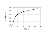
- FIG. 6 is a waveform diagram of a rectangular wave current input to a DFB-LD in an embodiment of the present invention. It is an example of the graph which shows the time change of the wavelength with respect to the input of the square wave current of DFB-LD.
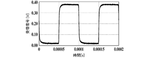
- the graph showing the light reception signal time series data shows the example at the time of non-detection.
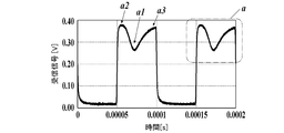
- the graph showing the light reception signal time series data in an embodiment of the present invention shows an example at the time of detection.
- 3B is a graph showing received light signal time-series data in the embodiment of the present invention, and is a partially enlarged view of FIG. 3B.
- 1 is a configuration block diagram of a gas measuring device according to an embodiment of the present invention. It is an example of a graph showing reference received light signal time series data in one embodiment of the present invention. It is a graph of an example showing the light reception signal time series data in one embodiment of the present invention. It is a block diagram of the configuration of the apparatus divided into a light projecting unit and a light receiving unit according to another embodiment of the present invention. In one Embodiment of this invention, the graph showing the light reception signal time series data shows the example at the time of non-detection.
- the graph showing the light reception signal time series data in an embodiment of the present invention shows an example at the time of detection.
- the graph showing the light reception signal time-series data in an embodiment of the present invention shows an example at the time of measurement error. It is a schematic diagram explaining the outline of the distance measurement principle utilized in one Embodiment of this invention.
- the absorption wavelength of the measurement target gas is set within this wavelength change range.
- received light signal time-series data as shown in FIG. 3A or FIG. 3B is obtained.
- FIG. 3A shows a case where there is no measurement target gas in the measurement target space, and a substantially rectangular waveform is obtained.
- light having an absorption wavelength is absorbed according to its concentration thickness product. Therefore, as shown in FIG. 3B, a negative peak a1 occurs on each top surface of one rectangular portion a.
- the concentration thickness product of the measurement target gas is determined by the relativity between the negative peak a1 and the positive peak a2 or a3. It can be calculated. For example, as shown in FIG. 3C, the concentration thickness product of the measurement target gas is calculated based on the difference between the light reception signal of the negative peak a1 and the light reception signal of the positive peak a2.
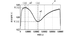
- the response characteristic of the wavelength change when a steep current change is added to the input current of the light emitting element as described above also depends on the temperature as shown in FIG. As shown in FIG. 4, since the timing of crossing the absorption wavelength ⁇ 1 varies depending on the temperature, it is preferable to keep the temperature of the light emitting element constant.
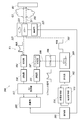
- FIG. 5 shows a configuration diagram of an example of a gas measuring apparatus according to the present invention.
- the gas measurement device 100 includes a light emitting unit 102 that emits light (measurement light 101) for detecting the measurement target gas G1, a control unit 103 that controls light emission of the light emitting unit 102, and a light emitting unit.
- a light receiving unit 104 that receives light (reflected by the reflector R1) that has emitted light 102 and passed through the measurement target space S1 and a calculation unit 105 that processes the signal V1 received by the light receiving unit 104 are provided.
- the gas measuring apparatus 100 includes a reference 106 indicating the light absorption wavelength of the measurement target gas, and a reference light receiving unit 107 that receives light emitted from the light emitting unit 102 and passed through the reference 106. Further, the gas measuring apparatus 100 includes a beam splitter 109 that distributes the light emitted from the light emitting unit 102 to the measuring light 101 and the light 108 for reference 106, an amplifier 110 that amplifies the detection value of the light receiving unit 104, and a reference light receiving unit. An amplifier 111 that amplifies the detection value 107, an amplifier 110, an AD converter 112 that AD converts each output signal of the amplifier 111, and the like are provided.
- the light emitting unit 102 includes a distributed feedback laser diode (DFB-LD) as a light emitting element.
- the calculation unit 105 obtains light reception signal time-series data from the AD converter 112 over the absorption wavelength and non-absorption wavelength of the gas G1 received by the light receiving unit 104.
- the computing unit 105 obtains, from the AD converter 112, reference received light signal time-series data over the absorption wavelength and non-absorption wavelength of the gas G1 received by the reference light receiving unit 107.
- the reference 106 is another substance or structure that responds at the same wavelength as the wavelength to which the measurement object itself or the measurement object reacts.
- a gas cell containing a substance to be measured can be used as the reference 106.
- the control unit 103 obtains feedback of the light receiving signal of the reference light receiving unit 107 and controls the current control unit 113 so that the reference light receiving signal time-series data has a negative peak a1. By inputting the current, a change over the absorption wavelength and the non-absorption wavelength of the measurement target gas G1 is given to the wavelength of the light emitted from the light emitting unit 102. Meanwhile, the control unit 103 controls the temperature control unit 114 to keep the temperature of the light emitting unit 102 constant.
- the temperature control unit 114 includes a temperature control element such as a Peltier element.
- the calculation unit 105 is based on the light reception signal of the absorption wavelength light received by the light reception unit 104 and the light reception signal of the light of the non-absorption wavelength (light reception signal time-series data). ) Is calculated.
- Each functional block (arithmetic unit 105, control unit 103, temperature control unit 114, and current control unit 113) is, for example, a CPU (Central Processing Unit) ROM (Read Only Memory), RAM (Random Access Memory), external storage This is realized by referring to a control program and various data stored in a device (for example, a flash memory or a hard disk). However, some or all of the functional blocks may be realized by processing by a DSP (Digital Signal Processor) instead of or by processing by the CPU. Similarly, a part or all of each functional block may be realized by processing by a dedicated hardware circuit instead of or together with processing by software. An example of the calculation method of the calculation unit 105 is given below.
- the concentration of the measurement target gas based on the difference V ( ⁇ 2) / V ( ⁇ 1) between the light reception signal V ( ⁇ 2) of the negative peak a1 and the light reception signal V ( ⁇ 1) of the positive peak a2.
- the thickness product is calculated.
- the light reception signal V ( ⁇ 1) corresponds to the light reception signal of the light having the absorption wavelength ⁇ 1 received by the light reception unit 104
- the light reception signal V ( ⁇ 2) corresponds to the light reception signal of the light of the non-absorption wavelength ⁇ 2 received by the light reception unit 104. From this, the concentration-thickness product is calculated in the same manner as the conventional differential absorption method (DIAL, DOAS).
- the method of calculating the concentration thickness product from the signal obtained from the difference between the signal of the absorption band to be measured and the signal of the non-absorption band based on Lambert Beer's law as follows.
- the measurement target gas G1 exists on the optical path of the measurement light 101.
- the intensity of the laser beam having the absorption wavelength ⁇ 1 is expressed by the following equation 1 of Lambert-Beer as follows:
- the laser light with the non-absorption wavelength ⁇ 2 has a lower absorption rate and transmits better than the laser light with the absorption wavelength ⁇ 1, even if the measurement target gas G1 is generated during the passage of the laser light. Therefore, it can be assumed that the intensity of the laser beam is hardly affected even if the measurement target gas G1 is present during the passage of the laser beam. Therefore, it is considered that the difference in the intensity of the laser beam between the transmitting side and the receiving side with respect to each laser beam is generated according to the concentration thickness product of the measurement target gas G1.
- the above processing is basic, but the simplest processing system can be configured as follows.
- the laser light having the absorption wavelength ⁇ 1 is absorbed by the measurement target gas G1, and the intensity It1 of the weakened laser light is detected.
- the laser light having the non-absorption wavelength ⁇ 2 is slightly absorbed by the measurement target gas G1 and weakened.
- the intensity It2 of the laser beam is detected.
- Ii2 ⁇ It2 holds when there is no significant difference between the intensity on the transmission side and the intensity on the reception side (when the scattering coefficient is approximately 1).
- the arithmetic unit 105 synchronizes with the input timing signal of the rectangular wave current by the control unit 103 and the light emitted from the light emitting unit 102 in accordance with the input of the rectangular wave current as shown in FIG. It is preferable that it is possible to refer to the time change characteristic data of the wavelengths.
- the input of the rectangular wave current and the acquisition of the received light signal are executed a plurality of times during a predetermined time, and the average value is calculated based on the received light signals for a plurality of times corresponding to all or a part thereof, for example. For example, the concentration-thickness product may be calculated.
- the calculation unit 105 integrates the reference light reception signal time-series data in an absorption line light reception period t1 for receiving light having an absorption wavelength. For example, as shown in FIG. 6A, an area corresponding to the drop of the graph is set as a calculation target, and an integral value is obtained. This is referred to as “reference absorption band integral value Ar”. Further, as shown in FIG. 6A, the arithmetic unit 105 integrates the reference light reception signal time-series data in a non-absorption line light reception period t2 for receiving light of a non-absorption wavelength, and obtains an integral value. This is referred to as “reference non-absorption band integral value Nr”.
- the calculation unit 105 integrates the light reception signal time-series data in an absorption line light reception period t3 in which light having an absorption wavelength is received.
- the area corresponding to the drop of the graph is set as a calculation target, and an integral value is obtained. This is defined as “measurement target absorption band integral value As”.
- the arithmetic unit 105 integrates the received light signal time-series data in a non-absorbing line light receiving period t4 for receiving light having a non-absorbing wavelength to obtain an integrated value. This is defined as “measurement target non-absorption band integral value Ns”.
- the computing unit 105 calculates the concentration / thickness product of the measurement target gas G ⁇ b> 1 based on the values Ar, Nr, As, Ns and the concentration / thickness product of the reference 106.
- the input of the rectangular wave current and the acquisition of the light reception signal are executed a plurality of times during a predetermined time, and based on the light reception signals for a plurality of times corresponding to all or a part thereof, for example, the average
- the concentration / thickness product may be calculated by calculating a value.
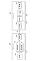
- the light emitting unit 102 is not limited to the device form that receives the reflected light from the reflector R1 as shown in FIG. It may be an apparatus in which the light receiving unit 104 is disposed so as to face the measurement target space S1.
- a scanning mechanism 115 that scans the measurement target space S ⁇ b> 1 with light emitted from the light emitting unit 102 (measurement light 101) may be provided.
- the scanning mechanism 115 includes a mirror 115a that reflects the measurement light 101 that is emitted and received, and a drive unit 115b that rotationally drives the mirror 115a.
- the drive unit 115 b includes an actuator (motor) that rotates the mirror 115 a and a drive circuit thereof, and rotates the mirror 115 a based on a control signal from the control unit 103.
- the scanning mechanism 115 can measure a one-dimensional and two-dimensional distribution of density thickness products.
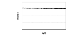
- FIG. 8A shows a normal case without light absorption by gas
- FIG. 8B shows a normal case with light absorption by gas.
- the received light intensity at the negative peak a1 due to light absorption of the gas can vary depending on the gas concentration thickness product.
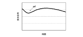
- the amount of change at a position other than the absorption line position a1 on the time axis does not change greatly depending on the presence or absence of gas and the concentration thickness product. If there is a significant waveform disturbance at a position on the time axis (for example, a4 in FIG. 8C) that does not vary greatly depending on the presence / absence of the gas and the concentration / thickness product, the environment other than the measurement target gas G1 at the measurement light emission destination Since there is a high possibility of wavelength disturbance due to factors or the like, the measurement result of the measurement target gas G1 is also unreliable.
- the calculation unit 105 determines that the measurement error has occurred when the amount of change exceeds a specified value.
- the principle of distance measurement is based on the TOF method (Time Of Flight). As schematically shown in FIG. 9, the distance L between the gas measuring device 100 and the reflector R1 (received from the light emitting unit 102) is received based on the time ⁇ until the emitted light is reflected by the reflector R1 and returns. 2L) for the optical path distance to the unit 104 is measured by the following equation.
- the calculation unit 105 measures the optical path distance from the light emitting unit 102 to the light receiving unit 104 based on the time difference ⁇ between the light emission timing of the light emitting unit 102 and the light reception timing of the light receiving unit 104.
- 2L corresponds to the distance across the space S1 in the above formula.
- the “concentration thickness product” per unit length of the measurement target gas G1 that is, the concentration (average concentration) can be calculated based on the distance measured each time or the known distance.
- the “concentration thickness product” is converted into the “concentration thickness product” per unit length, that is, the concentration (average concentration). You may calculate by a value. Although it is theoretically possible even with the 2f method, the wavelength needs to be modulated in the vicinity of the absorption line, so that the amplitude is very small and distance measurement becomes difficult. On the other hand, since pulse emission is possible according to the present invention, unlike the 2f detection method, if the circuit has a clock function, the distance can be measured by one emission, and the circuit configuration can be easily measured. realizable.
- the light emitting unit by inputting the current that changes sharply between two values having a drop to the light emitting unit 102, the light emitting unit can be used by utilizing the response characteristics of the DFB-LD. Since the change over the absorption wavelength and non-absorption wavelength of the measurement target gas G1 is given to the wavelength of the light emitted by the light 102, it is possible to detect light emission and light reception and to calculate the concentration thickness product with a relatively simple configuration.
- the light emission output can be kept constant by keeping the light emission constant, and the light output can be changed over the absorption wavelength and the non-absorption wavelength while the light emission output is kept constant.
- the apparatus configuration is as simple as or better than the 2f detection method, and the optical path distance can be measured.
- the absorption wavelength and non-absorption wavelength can be oscillated only by driving control of the laser light source, and the measurement can be performed with one detector. Therefore, the calculation of the gas concentration / thickness product can be realized with a very simple configuration.
- pulsed light emission is advantageous in improving measurable distance and SN because it can output with high power while maintaining eye safety state compared to CW light emission.
- S / N can be improved by calculating not only for one rectangular part a but also for a plurality of continuous rectangular parts a and calculating a measurement result based on the calculation result. . At this time, the S / N can be further improved by excluding the rectangular portion a determined as an error from the calculation target.
- the present invention can be used for gas measurement and gas measurement devices.
Landscapes
- Physics & Mathematics (AREA)
- Spectroscopy & Molecular Physics (AREA)
- Analytical Chemistry (AREA)
- Health & Medical Sciences (AREA)
- Life Sciences & Earth Sciences (AREA)
- Chemical & Material Sciences (AREA)
- Optics & Photonics (AREA)
- Biochemistry (AREA)
- General Health & Medical Sciences (AREA)
- General Physics & Mathematics (AREA)
- Immunology (AREA)
- Pathology (AREA)
- Investigating Or Analysing Materials By Optical Means (AREA)
Abstract
La présente invention concerne un dispositif de mesure de gaz qui peut émettre de la lumière ainsi que recevoir et détecter de la lumière, et peut calculer un produit de densité-d'épaisseur, à l'aide d'une configuration relativement simple, et avec lequel une longueur d'onde peut être variée et émise à travers des longueurs d'onde d'absorption et des longueurs d'onde de non absorption, la sortie de lumière émise étant maintenue constante. Un dispositif de mesure de gaz (100) est pourvu d'une unité d'émission de lumière (102) qui émet de la lumière pour détecter un gaz qui doit être mesuré, d'une unité de commande (103), d'une unité de réception de lumière (104) et d'une unité de logique arithmétique (105) qui traite un signal reçu par l'unité de réception de lumière. Le dispositif de mesure de gaz (100) calcule un produit de densité-d'épaisseur d'un gaz qui doit être mesuré (G1) dans un espace (S1). L'unité de commande entre un courant électrique variant fortement dans l'unité d'émission de lumière afin de provoquer la variation de la longueur d'onde de la lumière émise par l'unité d'émission de lumière à travers des longueurs d'onde d'absorption et des longueurs d'onde de non absorption du gaz qui doit être mesuré. L'unité de logique arithmétique calcule le produit de densité-d'épaisseur du gaz qui doit être mesuré, sur la base d'un signal de réception de lumière de la lumière ayant une longueur d'onde d'absorption, et d'un signal de réception de lumière de la lumière ayant une longueur d'onde de non absorption, reçues par l'unité de réception de lumière.
Priority Applications (1)
| Application Number | Priority Date | Filing Date | Title |
|---|---|---|---|
| JP2018507260A JP6756999B2 (ja) | 2016-03-22 | 2017-03-15 | ガス測定装置 |
Applications Claiming Priority (2)
| Application Number | Priority Date | Filing Date | Title |
|---|---|---|---|
| JP2016056664 | 2016-03-22 | ||
| JP2016-056664 | 2016-03-22 |
Publications (1)
| Publication Number | Publication Date |
|---|---|
| WO2017164033A1 true WO2017164033A1 (fr) | 2017-09-28 |
Family
ID=59900309
Family Applications (1)
| Application Number | Title | Priority Date | Filing Date |
|---|---|---|---|
| PCT/JP2017/010390 WO2017164033A1 (fr) | 2016-03-22 | 2017-03-15 | Appareil de mesure de gaz |
Country Status (2)
| Country | Link |
|---|---|
| JP (1) | JP6756999B2 (fr) |
| WO (1) | WO2017164033A1 (fr) |
Cited By (1)
| Publication number | Priority date | Publication date | Assignee | Title |
|---|---|---|---|---|
| CN114220000A (zh) * | 2021-11-23 | 2022-03-22 | 慧之安信息技术股份有限公司 | 一种基于深度学习的加油站吸烟行为检测告警方法 |
Citations (9)
| Publication number | Priority date | Publication date | Assignee | Title |
|---|---|---|---|---|
| JPS586258U (ja) * | 1981-07-06 | 1983-01-14 | 株式会社東芝 | 分光分析計 |
| JPS58143242A (ja) * | 1982-02-19 | 1983-08-25 | Fujitsu Ltd | 漏洩ガス検出装置 |
| JPH04151546A (ja) * | 1990-10-15 | 1992-05-25 | Anritsu Corp | ガス検出装置 |
| JP2001074654A (ja) * | 1999-08-31 | 2001-03-23 | Mitsubishi Heavy Ind Ltd | ガス濃度計測装置及び燃焼炉 |
| JP2005522694A (ja) * | 2002-04-09 | 2005-07-28 | カスケイド テクノロジーズ リミテッド | 半導体ダイオードを使用したレーザ分光装置およびレーザ分光法 |
| JP2008076182A (ja) * | 2006-09-20 | 2008-04-03 | Denso Corp | 赤外線式ガス検知装置およびそのガス検知方法 |
| JP2009276308A (ja) * | 2008-05-19 | 2009-11-26 | Nippon Signal Co Ltd:The | ガス計測装置 |
| US20120136483A1 (en) * | 2010-11-30 | 2012-05-31 | Alstom Technology Ltd | Method of analyzing and controlling a combustion process in a gas turbine and apparatus for performing the method |
| JP2014055858A (ja) * | 2012-09-12 | 2014-03-27 | Tokyo Metropolitan Sewerage Service Corp | ガス濃度測定装置 |
Family Cites Families (1)
| Publication number | Priority date | Publication date | Assignee | Title |
|---|---|---|---|---|
| JP2014102152A (ja) * | 2012-11-20 | 2014-06-05 | Fuji Electric Co Ltd | レーザ式ガス分析計 |
-
2017
- 2017-03-15 WO PCT/JP2017/010390 patent/WO2017164033A1/fr active Application Filing
- 2017-03-15 JP JP2018507260A patent/JP6756999B2/ja active Active
Patent Citations (9)
| Publication number | Priority date | Publication date | Assignee | Title |
|---|---|---|---|---|
| JPS586258U (ja) * | 1981-07-06 | 1983-01-14 | 株式会社東芝 | 分光分析計 |
| JPS58143242A (ja) * | 1982-02-19 | 1983-08-25 | Fujitsu Ltd | 漏洩ガス検出装置 |
| JPH04151546A (ja) * | 1990-10-15 | 1992-05-25 | Anritsu Corp | ガス検出装置 |
| JP2001074654A (ja) * | 1999-08-31 | 2001-03-23 | Mitsubishi Heavy Ind Ltd | ガス濃度計測装置及び燃焼炉 |
| JP2005522694A (ja) * | 2002-04-09 | 2005-07-28 | カスケイド テクノロジーズ リミテッド | 半導体ダイオードを使用したレーザ分光装置およびレーザ分光法 |
| JP2008076182A (ja) * | 2006-09-20 | 2008-04-03 | Denso Corp | 赤外線式ガス検知装置およびそのガス検知方法 |
| JP2009276308A (ja) * | 2008-05-19 | 2009-11-26 | Nippon Signal Co Ltd:The | ガス計測装置 |
| US20120136483A1 (en) * | 2010-11-30 | 2012-05-31 | Alstom Technology Ltd | Method of analyzing and controlling a combustion process in a gas turbine and apparatus for performing the method |
| JP2014055858A (ja) * | 2012-09-12 | 2014-03-27 | Tokyo Metropolitan Sewerage Service Corp | ガス濃度測定装置 |
Non-Patent Citations (1)
| Title |
|---|
| YMANNISHI, MASAMICHI ET AL., DEVELOPMENT OF QUANTUM CASCADE LASERS AND THEIR APPLICATIONS, vol. 40, no. 3, 2011, pages 142 - 147 * |
Cited By (1)
| Publication number | Priority date | Publication date | Assignee | Title |
|---|---|---|---|---|
| CN114220000A (zh) * | 2021-11-23 | 2022-03-22 | 慧之安信息技术股份有限公司 | 一种基于深度学习的加油站吸烟行为检测告警方法 |
Also Published As
| Publication number | Publication date |
|---|---|
| JP6756999B2 (ja) | 2020-09-16 |
| JPWO2017164033A1 (ja) | 2019-01-31 |
Similar Documents
| Publication | Publication Date | Title |
|---|---|---|
| US5815277A (en) | Deflecting light into resonant cavities for spectroscopy | |
| EP1966627B1 (fr) | Dispositif et procede permettant de mesurer un mouvement relatif | |
| US9001854B2 (en) | Methods for determining optical power, for power-normalizing laser measurements, and for stabilizing power of lasers via compliance voltage sensing | |
| KR101303371B1 (ko) | 소정 범위의 속도들에 걸친 객체와 광 입력 장치의 상대이동을 측정하는 방법 | |
| EP2839554B1 (fr) | Système laser à fréquence réglable | |
| US20160377719A1 (en) | Laser range finding apparatus | |
| JP6793033B2 (ja) | 測距装置 | |
| US20200182980A1 (en) | Optical device | |
| US7986398B2 (en) | Gas velocity sensor | |
| US20180266967A1 (en) | Optical test apparatus | |
| WO2017164033A1 (fr) | Appareil de mesure de gaz | |
| JP5600374B2 (ja) | テラヘルツ分光装置 | |
| JP7088494B2 (ja) | 物質検出装置 | |
| KR101604867B1 (ko) | 분광기술을 적용한 검지장치 | |
| JP7352962B2 (ja) | ブリルアン周波数シフト測定装置及びブリルアン周波数シフト測定方法 | |
| US10809189B2 (en) | Optical measurement device and optical measurement method | |
| JP2015062914A (ja) | レーザ照射システムおよび脆弱部位検知システム | |
| JP2008008842A (ja) | 電磁波測定装置 | |
| JP7110686B2 (ja) | 濃度測定装置 | |
| Jin et al. | A concept of multi-mode high spectral resolution lidar using Mach-Zehnder interferometer | |
| JPH07198328A (ja) | 位置測定装置 | |
| US10488250B2 (en) | Method and device for quantitatively sensing the power fraction of a radiation background of a pulsed laser | |
| JP2019023593A (ja) | レーザ変位計と、それを用いたレーザ超音波検査装置 | |
| JP5962327B2 (ja) | 濃度測定装置及び濃度測定方法 | |
| WO2023243365A1 (fr) | Dispositif laser |
Legal Events
| Date | Code | Title | Description |
|---|---|---|---|
| ENP | Entry into the national phase |
Ref document number: 2018507260 Country of ref document: JP Kind code of ref document: A |
|
| NENP | Non-entry into the national phase |
Ref country code: DE |
|
| 121 | Ep: the epo has been informed by wipo that ep was designated in this application |
Ref document number: 17770076 Country of ref document: EP Kind code of ref document: A1 |
|
| 122 | Ep: pct application non-entry in european phase |
Ref document number: 17770076 Country of ref document: EP Kind code of ref document: A1 |