WO2017163609A1 - モータの制御装置 - Google Patents
モータの制御装置 Download PDFInfo
- Publication number
- WO2017163609A1 WO2017163609A1 PCT/JP2017/003117 JP2017003117W WO2017163609A1 WO 2017163609 A1 WO2017163609 A1 WO 2017163609A1 JP 2017003117 W JP2017003117 W JP 2017003117W WO 2017163609 A1 WO2017163609 A1 WO 2017163609A1
- Authority
- WO
- WIPO (PCT)
- Prior art keywords
- cooling oil
- coil
- motor
- control device
- rotation operation
- Prior art date
- Legal status (The legal status is an assumption and is not a legal conclusion. Google has not performed a legal analysis and makes no representation as to the accuracy of the status listed.)
- Ceased
Links
Images


Classifications
-
- H—ELECTRICITY
- H02—GENERATION; CONVERSION OR DISTRIBUTION OF ELECTRIC POWER
- H02P—CONTROL OR REGULATION OF ELECTRIC MOTORS, ELECTRIC GENERATORS OR DYNAMO-ELECTRIC CONVERTERS; CONTROLLING TRANSFORMERS, REACTORS OR CHOKE COILS
- H02P29/00—Arrangements for regulating or controlling electric motors, appropriate for both AC and DC motors
- H02P29/60—Controlling or determining the temperature of the motor or of the drive
- H02P29/64—Controlling or determining the temperature of the winding
-
- B—PERFORMING OPERATIONS; TRANSPORTING
- B60—VEHICLES IN GENERAL
- B60K—ARRANGEMENT OR MOUNTING OF PROPULSION UNITS OR OF TRANSMISSIONS IN VEHICLES; ARRANGEMENT OR MOUNTING OF PLURAL DIVERSE PRIME-MOVERS IN VEHICLES; AUXILIARY DRIVES FOR VEHICLES; INSTRUMENTATION OR DASHBOARDS FOR VEHICLES; ARRANGEMENTS IN CONNECTION WITH COOLING, AIR INTAKE, GAS EXHAUST OR FUEL SUPPLY OF PROPULSION UNITS IN VEHICLES
- B60K6/00—Arrangement or mounting of plural diverse prime-movers for mutual or common propulsion, e.g. hybrid propulsion systems comprising electric motors and internal combustion engines
- B60K6/20—Arrangement or mounting of plural diverse prime-movers for mutual or common propulsion, e.g. hybrid propulsion systems comprising electric motors and internal combustion engines the prime-movers consisting of electric motors and internal combustion engines, e.g. HEVs
- B60K6/22—Arrangement or mounting of plural diverse prime-movers for mutual or common propulsion, e.g. hybrid propulsion systems comprising electric motors and internal combustion engines the prime-movers consisting of electric motors and internal combustion engines, e.g. HEVs characterised by apparatus, components or means specially adapted for HEVs
- B60K6/26—Arrangement or mounting of plural diverse prime-movers for mutual or common propulsion, e.g. hybrid propulsion systems comprising electric motors and internal combustion engines the prime-movers consisting of electric motors and internal combustion engines, e.g. HEVs characterised by apparatus, components or means specially adapted for HEVs characterised by the motors or the generators
-
- H—ELECTRICITY
- H02—GENERATION; CONVERSION OR DISTRIBUTION OF ELECTRIC POWER
- H02K—DYNAMO-ELECTRIC MACHINES
- H02K11/00—Structural association of dynamo-electric machines with electric components or with devices for shielding, monitoring or protection
- H02K11/20—Structural association of dynamo-electric machines with electric components or with devices for shielding, monitoring or protection for measuring, monitoring, testing, protecting or switching
- H02K11/25—Devices for sensing temperature, or actuated thereby
-
- H—ELECTRICITY
- H02—GENERATION; CONVERSION OR DISTRIBUTION OF ELECTRIC POWER
- H02K—DYNAMO-ELECTRIC MACHINES
- H02K9/00—Arrangements for cooling or ventilating
- H02K9/19—Arrangements for cooling or ventilating for machines with closed casing and closed-circuit cooling using a liquid cooling medium, e.g. oil
-
- H—ELECTRICITY
- H02—GENERATION; CONVERSION OR DISTRIBUTION OF ELECTRIC POWER
- H02P—CONTROL OR REGULATION OF ELECTRIC MOTORS, ELECTRIC GENERATORS OR DYNAMO-ELECTRIC CONVERTERS; CONTROLLING TRANSFORMERS, REACTORS OR CHOKE COILS
- H02P23/00—Arrangements or methods for the control of AC motors characterised by a control method other than vector control
- H02P23/0086—Arrangements or methods for the control of AC motors characterised by a control method other than vector control specially adapted for high speeds, e.g. above nominal speed
- H02P23/009—Arrangements or methods for the control of AC motors characterised by a control method other than vector control specially adapted for high speeds, e.g. above nominal speed using field weakening
-
- H—ELECTRICITY
- H02—GENERATION; CONVERSION OR DISTRIBUTION OF ELECTRIC POWER
- H02P—CONTROL OR REGULATION OF ELECTRIC MOTORS, ELECTRIC GENERATORS OR DYNAMO-ELECTRIC CONVERTERS; CONTROLLING TRANSFORMERS, REACTORS OR CHOKE COILS
- H02P23/00—Arrangements or methods for the control of AC motors characterised by a control method other than vector control
- H02P23/14—Estimation or adaptation of motor parameters, e.g. rotor time constant, flux, speed, current or voltage
Definitions
- This disclosure relates to a motor control device that is cooled by cooling oil in a housing.
- Patent Document 1 As a technique for preventing overheating of the motor, for example, there is one described in Patent Document 1. This is equipped with an oil temperature sensor that detects the temperature of oil in the motor housing, and calculates the winding temperature based on the oil temperature detected by the oil temperature sensor, the heat capacity and thermal resistance of the motor, and this winding The motor temperature is detected based on the temperature. The motor torque is limited when the detected motor temperature is equal to or higher than a predetermined value.
- the motor that is cooled by the cooling oil in the housing differs depending on the operating region. That is, since the cooling oil is lifted by the rotation of the rotor, the cooling oil is not sufficiently diffused and the coil is easily overheated in a region where the rotation speed of the motor (that is, the rotation speed of the rotor) is low. On the other hand, in a region where the rotational speed of the motor is high, the cooling oil is sufficiently diffused and the coil is difficult to overheat. However, since the amount of heat generated by the coil is large, the cooling oil easily overheats.
- Patent Document 1 does not take into consideration that the portion that is easily overheated differs depending on the motor operating region as described above, and the motor temperature is simply higher than a predetermined value. A problem has been found that sometimes only the output torque of the motor is limited, so that a part that is likely to overheat may not be properly protected.
- an object of the present disclosure is to provide a motor control device that can appropriately protect a portion that is easily overheated in a motor cooled by cooling oil in a housing.
- the present disclosure is a motor control device configured by a stator and a rotor arranged in a housing and a motor that is cooled by cooling oil in the housing.
- the control device includes a coil temperature detection unit, a cooling oil temperature detection unit (32), and a control unit.
- the coil temperature detection means detects the temperature of the coil provided in the stator.
- the cooling oil temperature detection means detects the temperature of the cooling oil.
- the control unit executes a coil protection torque limit and a cooling oil protection torque limit.
- the coil protection torque limit is to limit the motor torque when the coil temperature detected by the coil temperature detection means exceeds the coil protection threshold.
- the cooling oil protection torque limit is to limit the motor torque when the temperature of the cooling oil detected by the cooling oil temperature detection means exceeds a cooling oil protection threshold.
- the control unit makes it easier to preferentially execute the coil protection torque limit, and the motor operates at a higher rotation than the low-rotation operation region.
- the torque limitation for cooling oil protection is preferentially executed.
- the present disclosure is not limited to the configuration in which the motor is cooled by the cooling oil sealed in the housing, but includes a configuration in which the motor is cooled by the cooling oil introduced into the housing from the outside.
- overheating of the coil is prevented by executing the coil protection torque limit that limits the motor torque when the coil temperature detected by the coil temperature detection unit exceeds the coil protection threshold. be able to. Also, cooling oil protection torque limit that limits the motor torque when the cooling oil temperature detected by the cooling oil temperature detection means exceeds the cooling oil protection threshold value prevents overheating of the cooling oil. can do.
- the coil protection torque limitation is preferentially executed in the low rotation operation region where the coil is likely to overheat to ensure overheating of the coil. Therefore, the coil can be appropriately protected.
- the cooling oil protection torque limitation is preferentially executed in the high rotation operation region in which the cooling oil is likely to overheat. Overheating can be reliably prevented, and the cooling oil can be appropriately protected.
- FIG. 1 is a diagram illustrating a schematic configuration of a control system for a hybrid vehicle according to a first embodiment of the present disclosure.
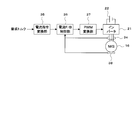
- FIG. 2 is a block diagram illustrating MG torque control.
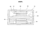
- FIG. 3 is a longitudinal sectional view showing a schematic configuration of the MG of the first embodiment.
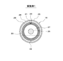
- FIG. 4 is a cross-sectional view showing a schematic configuration of the MG of the first embodiment.
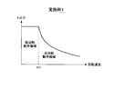
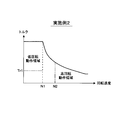
- FIG. 5 is a diagram illustrating area divisions according to the first embodiment.
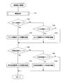
- FIG. 6 is a flowchart showing the flow of processing of the overheat prevention control routine.
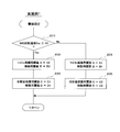
- FIG. 7 is a flowchart showing the flow of processing of the threshold setting routine of the first embodiment.
- FIG. 8 is a diagram showing area divisions according to the second embodiment.
- FIG. 1 is a diagram illustrating a schematic configuration of a control system for a hybrid vehicle according to a first embodiment of the present disclosure.
- FIG. 2 is a block diagram illustrating MG torque control.
- FIG. 3 is
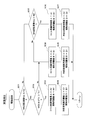
- FIG. 9 is a flowchart showing a flow of processing of a threshold setting routine according to the second embodiment.
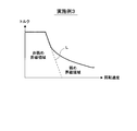
- FIG. 10 is a diagram illustrating area divisions according to the third embodiment.
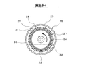
- FIG. 11 is a cross-sectional view showing a schematic configuration of the MG of the fourth embodiment.
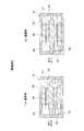
- FIG. 12 is a longitudinal sectional view showing a schematic configuration of the MG of the fifth embodiment.
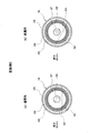
- FIG. 13 is a cross-sectional view showing a schematic configuration of the MG of the sixth embodiment.
- FIG. 14 is a diagram illustrating a schematic configuration of a hybrid vehicle control system according to the seventh embodiment.
- Example 1 of the present disclosure will be described with reference to FIGS.
- An engine 11 serving as a power source for the vehicle and a transmission 12 connected to the engine 11 are mounted on the front side of the vehicle.
- the transmission 12 is a mechanical transmission, and may be a stepped transmission that switches a shift stage step by step from among a plurality of shift stages, or a continuously variable transmission (so-called CVT) that changes continuously. ).
- the engine 11 and the transmission 12 are arranged horizontally so that the axial direction of the output shaft (that is, the crankshaft) of the engine 11 is the left-right direction of the vehicle.
- the power of the output shaft of the engine 11 is transmitted to the transmission 12, and the power of the output shaft of the transmission 12 is transmitted to the drive shaft 14 of the wheel 15 via the differential gear mechanism 13 and the like.
- a small-diameter motor generator (hereinafter referred to as “MG”) 16 serving as a power source for the vehicle and a small-diameter speed reducer 17 connected to the MG 16 are mounted behind the engine 11 and the transmission 12. .
- the MG 16 and the speed reducer 17 are arranged vertically so that the axial direction of the output shaft is the front-rear direction of the vehicle.
- the output shaft of the speed reducer 17 is connected to the ring gear 19 of the differential gear mechanism 13 (that is, the gear to which the power of the output shaft of the transmission 12 is input) via the transfer 20.
- the power of the output shaft of the MG 16 is transmitted to the speed reducer 17, and the power of the output shaft of the speed reducer 17 is transmitted to the drive shaft 14 of the wheel 15 via the transfer 20, the differential gear mechanism 13, and the like.
- an inverter 21 for driving the MG 16 is connected to the high voltage battery 22, and the MG 16 exchanges power with the high voltage battery 22 via the inverter 21.
- the high voltage battery 22 is a direct current power source including a secondary battery.
- the inverter 21 converts the DC voltage of the high-voltage battery 22 into an AC voltage and drives the MG 16 according to a torque command value from an HV-ECU 23 described later, and drives the MG 16 while limiting the torque command value as necessary.
- the HV-ECU 23 is a control device that comprehensively controls the entire vehicle and reads output signals from various sensors and switches (for example, an accelerator sensor, a shift switch, a brake switch, a vehicle speed sensor, etc.) Is detected.
- the HV-ECU 23 transmits and receives control signals and data signals to and from the MG-ECU 24 and an engine ECU (not shown).
- the MG-ECU 24 is a control device that controls the inverter 21 to control the MG 16, and the engine ECU is a control device that controls the operation of the engine 11.
- the HV-ECU 23 controls the engine 11, the MG 16 and the like according to the driving state of the vehicle by each ECU. At that time, the HV-ECU 23 switches the travel mode among, for example, an engine travel mode, an assist travel mode, and an EV travel mode.
- engine travel mode engine travel is performed in which the vehicle 15 travels by driving the wheels 15 with only the power of the engine 11 of the engine 11 and the MG 16.
- assist travel mode assist travel is performed in which the vehicle 15 travels by driving the wheels 15 with both the power of the engine 11 and the power of the MG 16.
- EV traveling mode EV traveling is performed in which the vehicle 15 is driven by driving the wheels 15 with only the power of the MG 16 of the engine 11 and the MG 16.
- the HV-ECU 23 switches the traveling mode to the regenerative power generation mode when braking the vehicle (for example, when generating a braking force when the accelerator is off or the brake is on).
- the MG 16 is driven by the power of the wheels 15 to perform regenerative power generation by converting the kinetic energy of the vehicle into electric energy by the MG 16, and the high-voltage battery 22 is charged with the regenerative power that is the generated power.
- the MG 16 is, for example, a three-phase permanent magnet type synchronous motor and has a built-in permanent magnet, and is equipped with a rotational position sensor 38 that detects the rotational position ⁇ (that is, the rotational angle) of the rotor 27.
- the inverter 21 converts the DC voltage of the high-voltage battery 22 into the three-phase AC voltage U, V, V, based on the three-phase six-arm voltage command signals UU, UL, VU, VL, WU, WL output from the MG-ECU 24. It converts to W and drives MG16.
- the current sensor 34 detects the U-phase current iu flowing in the U-phase of the MG 16 and the W-phase current iw flowing in the W-phase.
- the MG-ECU 24 executes torque control for adjusting the AC voltage applied to the MG 16 by controlling the inverter 21 so that the output torque of the MG 16 becomes the required torque (that is, the torque command value).
- a current F for feedback-controlling the energization of the MG 16 so that the deviation between the current command value based on the required torque output from the HV-ECU 23 and the current detection value based on the output of the current sensor 34 becomes small.
- the / B control is executed as follows. At that time, in the dq coordinate system, which is the rotational coordinate system set as the rotor rotational coordinate of the MG 16, the d-axis current id and the q-axis current iq are independently feedback controlled.
- the MG-ECU 24 uses the current command conversion unit 35 to map the command current vectors (d-axis current command value Id, q-axis current command value Iq) based on the required torque and rotation speed of the MG 16 using a map or a mathematical formula. Calculate.
- the detection current vector (d-axis current detection value id, q-axis current detection value iq), which is the detection value of the current flowing through the, is calculated.
- the d-axis voltage command value Vd is calculated by PI control or the like so that the deviation ⁇ id between the d-axis current command value Id and the d-axis current detection value id becomes small, and the q-axis current command value Iq and the q-axis current detection are performed.
- the q-axis voltage command value Vq is calculated by PI control or the like so that the deviation ⁇ iq from the value iq becomes small, and command voltage vectors (d-axis voltage command value Vd, q-axis voltage command value Vq) are obtained.
- the PWM converter 37 performs three-phase modulation or two-phase modulation for three-phase modulation based on the command voltage vector (d-axis voltage command value Vd, q-axis voltage command value Vq) and the rotor rotational position ⁇ of MG16.
- the voltage command values Vu, Vv, Vw are calculated, and these three-phase voltage command values Vu, Vv, Vw are converted into three-phase six-arm voltage command signals UU, UL, VU, VL, WU, Convert to WL.
- These three-phase six-arm voltage command signals UU, UL, VU, VL, WU, WL are output to the inverter 21.
- a rotor 27 that rotates integrally with the rotary shaft 26 and a stator 28 that is disposed on the outer peripheral side of the rotor 27 are provided in the housing 25 of the MG 16.
- a coil 29 made up of a plurality of phase windings is wound around the stator 28.
- a cooling oil 30 for cooling the MG 16 is enclosed in a sealed space in the housing 25.
- the cooling oil 30 is stored up to a height position above the lowermost surface of the rotor 27 and below the rotating shaft 26 of the rotor 27 in a state where the rotation of the MG 16 is stopped.
- the cooling oil 30 is scraped up by the rotation of the rotor 27 and diffused into the housing 25.
- the cooling oil 30 is an insulating liquid, and for example, lubricating oil for automobiles such as hydraulic oil for automatic transmission (so-called ATF) is used.
- a coil temperature sensor 31 that detects the temperature of the coil 29 and a cooling oil temperature sensor 32 that detects the temperature of the cooling oil 30 are provided in the housing 25.
- the coil temperature sensor 31 is installed in a position where the coil 29 is not immersed in the cooling oil 30 when the rotation of the MG 16 is stopped. Further, the coil temperature sensor 31 is installed so as to be located inside the coil 29 (that is, on the inner peripheral side) and at a neutral point 33 of the coil 29.
- the cooling oil temperature sensor 32 is installed at a position immersed in the cooling oil 30 and away from the coil 29 (that is, a position not in contact with the coil 29). Furthermore, the cooling oil temperature sensor 32 is installed so as to be positioned below the lowest surface of the rotor 27.
- the output signal of the coil temperature sensor 31 and the output signal of the cooling oil temperature sensor 32 are input to the MG-ECU 24.
- the MG-ECU 24 executes a routine for preventing overheating shown in FIGS. Perform prevention control.
- the coil protection torque limit is performed to limit the torque of the MG 16.
- the cooling oil protection torque limit is executed to limit the torque of the MG 16.
- the MG-ECU 24 described above controls the inverter 21 to reduce the AC voltage applied to the MG 16. Note that when the AC voltage applied to MG 16 is reduced, the torque output by MG 16 is reduced. Therefore, it is desirable that the HV-ECU 23 instructs the engine ECU to increase the engine output so as to compensate for the decrease in torque output from the MG 16.
- MG16 cooled with the cooling oil 30 in the housing 25 differs in the part which is easy to overheat depending on the operation region. That is, since the cooling oil 30 is lifted up by the rotation of the rotor 27, the cooling oil 30 is not sufficiently diffused and the coil 29 is easily overheated in a region where the rotation speed of the MG 16 (that is, the rotation speed of the rotor 27) is low. On the other hand, in the region where the rotational speed of the MG 16 is high, the cooling oil 30 is sufficiently diffused and the coil 29 is difficult to overheat. However, since the amount of heat generated by the coil 29 is large, the cooling oil 30 is likely to overheat.
- the operating range of the MG 16 is a low-rotation operation region where the MG 16 operates at a low rotation speed equal to or less than the predetermined rotation speed N 1 ⁇ , and the MG 16 rotates at a higher rotation speed than the predetermined rotation speed N 1. It is divided into high-rotation operation areas that operate at
- the coil protection torque limit is more preferentially executed than the cooling oil protection torque limit.
- the coil protection torque limit is prioritized (for example, earlier) than the cooling oil protection torque limit by setting the coil protection threshold A to a value lower than the high rotation operation area in the low rotation operation area. To make it easier to implement.
- This preferentially executes the coil protection torque limit in the low-rotation operation region where the coil 29 is likely to overheat, thereby reliably preventing the coil 29 from overheating. That is, by reducing the AC voltage applied to the MG 16, the amount of heat generated per unit time of the coil 29 is reduced, and overheating of the coil 29 is prevented.
- the torque limit for cooling oil protection is more preferentially executed than the torque limit for coil protection.
- the cooling oil protection torque limit has priority over the coil protection torque limit (for example, earlier). ) To be executed easily.
- the cooling oil protection torque limit is preferentially executed in the high-rotation operation region where the cooling oil 30 is likely to overheat, so that the overheating of the cooling oil 30 can be reliably prevented. That is, in order to reduce the alternating voltage applied to MG16, the emitted-heat amount per unit time of the coil 29 falls. Since the amount of heat transmitted from the coil 29 to the cooling oil 30 is also reduced, overheating of the cooling oil 30 is prevented.
- the overheat prevention control routine shown in FIG. 6 is repeatedly executed at a predetermined cycle during the power-on period of the MG-ECU 24, and serves as a control unit. Further, the threshold setting routine shown in FIG. 7 is a subroutine executed in step 101 of FIG. 6 and plays a role as a control unit.
- the threshold setting routine of FIG. 7 is executed.
- this threshold value setting routine is started, first, in step 201, it is determined whether or not the low-speed operation region is in accordance with whether or not the rotational speed NmN of the MG 16 is equal to or lower than a predetermined rotational speed N1.
- step 201 when it is determined that the rotation speed NmM of the MG 16 is equal to or less than the predetermined rotation speed N1, it is determined that the region is in the low rotation operation region. In this case, the process proceeds to step 202, where the coil protection threshold A is set to A2 (for example, 180 ° C.), and the release threshold B lower than the coil protection threshold A is set to B2.
- the coil protection threshold A is set to A2 (for example, 180 ° C.)
- the release threshold B lower than the coil protection threshold A is set to B2.
- A2 is set to a value lower than A1 (that is, A2 ⁇ A1)
- B2 is set to a value lower than B1 (that is, B2 ⁇ B1).
- the coil protection threshold A is set to a value lower than that in the high rotation operation region, so the coil protection torque limit has priority over the cooling oil protection torque limit.
- the above-mentioned “make it preferentially executed” does not mean that it is always executed preferentially.
- the temperature of the coil and the temperature of the cooling oil are not always expressed by the same relational expression, and the temperature difference between the two varies depending on the environmental conditions.
- the torque limitation for cooling oil protection is executed and the torque limitation for coil protection is not executed even in the low rotation operation region.
- the fact that the coil protection torque limit is more likely to be executed preferentially than the cooling oil protection torque limit is that the conditions under which the coil protection torque limit is executed before the cooling oil protection torque limit are wide. Means that. The same is true for the following.
- step 203 where the cooling oil protection threshold C is set to C1 (for example, 120 ° C.), and the release threshold D lower than the cooling oil protection threshold C is set to D1.
- Cooling oil protection threshold C C1
- C1 is set to a value higher than C2 (ie, C1> C2)
- D1 is set to a value higher than D2 (ie, D1> D2).
- step 201 when it is determined in step 201 that the rotational speed Nm of the MG 16 is higher than the predetermined rotational speed N1, it is determined as a high-rotation operation region. In this case, the process proceeds to step 204, where the coil protection threshold A is set to A1 (for example, 200 ° C.), and the release threshold B lower than the coil protection threshold A is set to B1.
- the coil protection threshold A is set to A1 (for example, 200 ° C.)
- the release threshold B lower than the coil protection threshold A is set to B1.
- A1 is set to a higher value than A2 (that is, A1> A2)
- B1 is set to a higher value than B2 (that is, B1> B2).
- the coil protection threshold A is set to a value higher than that in the low rotation operation region.
- step 205 the cooling oil protection threshold C is set to C2 (for example, 100 ° C.), and the release threshold D lower than the cooling oil protection threshold C is set to D2.
- Cooling oil protection threshold C C2
- C2 is set to a value lower than C1 (ie, C2 ⁇ C1)
- D2 is set to a value lower than D1 (ie, D2 ⁇ D1).
- the cooling oil protection threshold C is set to a value lower than that in the low rotation operation region, so that the cooling oil protection torque limit is greater than the coil protection torque limit. It is possible to facilitate execution with priority.
- step 102 If it is determined in step 102 that the temperature Tc of the coil 29 is higher than the coil protection threshold A, the process proceeds to step 103.
- the coil protection torque limit is executed to limit the torque of the MG 16 with a predetermined upper limit guard value (for example, energization of the MG 16 is controlled so that the torque of the MG 16 does not exceed the upper limit guard value).
- step 104 it is determined whether or not the temperature Tc ⁇ of the coil 29 detected by the coil temperature sensor 31 is lower than the release threshold B.
- step 104 If it is determined in step 104 that the temperature Tc of the coil 29 is lower than the release threshold B, the process proceeds to step 105 and the coil protection torque limit is released.
- step 106 it is determined whether or not the temperature To of the cooling oil 30 detected by the cooling oil temperature sensor 32 is higher than the cooling oil protection threshold C.
- step 106 If it is determined in step 106 that the temperature ToT of the cooling oil 30 is higher than the cooling oil protection threshold C, the process proceeds to step 107.
- torque limitation for cooling oil protection is executed to limit the torque of MG16 by a predetermined upper limit guard value (for example, energization of MG16 is controlled so that the torque of MG16 does not exceed the upper limit guard value).
- step 106 determines whether or not the temperature To of the cooling oil 30 is equal to or lower than the cooling oil protection threshold C. If it is determined in step 106 that the temperature To of the cooling oil 30 is equal to or lower than the cooling oil protection threshold C, the process proceeds to step 108. In this step 108, it is determined whether or not the temperature To of the cooling oil 30 detected by the cooling oil temperature sensor 32 is lower than the release threshold D.
- step 108 If it is determined in step 108 that the temperature ToT of the cooling oil 30 is lower than the release threshold D, the process proceeds to step 109, and the cooling oil protection torque limit is released.
- the coil protection torque limit that limits the torque of the MG 16 when the temperature Tc of the coil 29 detected by the coil temperature sensor 31 exceeds the coil protection threshold A is executed. 29 overheating can be prevented.
- a cooling oil protection torque limit that limits the torque of the MG 16 is executed. Overheating can be prevented.
- the coil protection torque limit is easily executed with priority. As a result, it is possible to preferentially execute the coil protection torque limit in the low-rotation operation region where the coil 29 is likely to overheat, thereby reliably preventing the coil 29 from being overheated, and appropriately protecting the coil 29.
- the torque limitation for cooling oil protection is made preferentially executed. Thereby, it is possible to preferentially execute the cooling oil protection torque limit in the high-rotation operation region where the cooling oil 30 is likely to be overheated, thereby reliably preventing the overheating of the cooling oil 30, and appropriately protecting the cooling oil 30. be able to.
- the coil protection torque limit is set to be preferentially executed by setting the coil protection threshold A to a value lower than the high rotation operation region in the low rotation operation region.
- the coil protection torque limitation can be started. it can.
- the coil protection torque limit can be preferentially executed in the low rotation operation region where the coil 29 is likely to overheat, and the coil 29 can be reliably protected.
- the torque limitation for cooling oil protection is made easier to be executed preferentially.
- the cooling oil protection torque limit can be preferentially executed in the high-rotation operation region where the cooling oil 30 is likely to overheat, and the cooling oil 30 can be reliably protected.
- the portion of the coil 29 that is not immersed in the cooling oil 30 when the rotation of the MG 16 is stopped is likely to be hotter than the portion that is immersed in the cooling oil 30. Furthermore, the inside of the coil 29 tends to be hotter than the outside of the coil 29.
- the neutral point of the coil 29 is a portion of the coil 29 that generates the most heat.
- the coil temperature sensor 31 is positioned not to be immersed in the cooling oil 30 in the coil 29 when the rotation of the MG 16 is stopped, and further to be positioned inside the coil 29 and at the neutral point of the coil 29. To be installed in. As a result, the temperature of the portion of the coil 29 that is likely to become high temperature can be detected by the coil temperature sensor 31, so that the coil protection torque limit based on the detection value of the coil temperature sensor 31 is started at an appropriate timing. Appropriate overheating can be prevented.
- the cooling oil temperature sensor 32 is immersed in the cooling oil 30 and installed at a position away from the coil 29. Thereby, the temperature of the cooling oil 30 can always be detected by the cooling oil temperature sensor 32. Further, since the cooling oil 30 is lifted by the rotation of the rotor 27, the cooling oil temperature sensor 32 is connected to the rotor 27 in consideration that the oil level of the cooling oil 30 does not fall below the lowest level surface of the rotor 27. It is designed to be installed below the lowermost surface. Thereby, the cooling oil temperature sensor 32 can always be immersed in the cooling oil 30.
- the cooling oil 30 is sealed in a sealed space in the housing 25 and is stored up to a height position above the lowermost surface of the rotor 27 and below the rotating shaft 26 of the rotor 27. ing.
- the cooling oil 30 By storing the cooling oil 30 to a height above the lowermost surface of the rotor 27, the heat inside the MG 16 is efficiently conducted to the housing 25 via the cooling oil 30 and released to the outside of the MG 16. And the MG 16 can be effectively cooled.
- the cooling oil 30 to a height position below the rotating shaft 26 of the rotor 27 the amount of the cooling oil 30 to be enclosed is moderately suppressed, and the rotational load of the MG 16 caused by the cooling oil 30 is moderately suppressed. Can do.
- the coil temperature sensor 31 is installed inside the coil 29 and at the neutral point of the coil 29.
- the present invention is not limited to this, and the coil temperature sensor 31 may be installed outside the coil 29 or other than the neutral point of the coil 29.
- Example 2 of the present disclosure will be described with reference to FIGS. 8 and 9. However, description of parts that are substantially the same as or similar to those in the first embodiment will be omitted or simplified, and parts different from those in the first embodiment will be mainly described.
- the low rotation operation region is divided into a region where the torque TmT of the MG 16 is larger than the predetermined value Tr1 and a region where the torque Trm is less than the predetermined value Tr1.
- the predetermined value Tr1 is set to, for example, an upper limit value of a torque that can be continuously operated without overheating of the MG 16 or a value slightly lower than that.
- the high-rotation operation region is divided into a region where the rotational speed NmM of the MG 16 is higher than a predetermined value N2 and a region below the predetermined value N2.
- the predetermined value N2 is set to, for example, an upper limit value of the rotational speed at which the cooling oil 30 and the air are mixed and diffused by the rotation of the rotor 27 (for example, a bubble state) or a value slightly lower than that. .
- the coil protection threshold A is set to the same value as in the high rotation operation region in the low rotation operation region and in the region where the torque Tm of the MG 16 is equal to or less than the predetermined value Tr1. Further, in the high rotation operation region and the region where the rotation speed Nm of the MG 16 is equal to or less than a predetermined value N2, the cooling oil protection threshold C is set to the same value as that in the low rotation operation region.
- step 301 it is determined whether or not the low-speed operation region is in accordance with whether or not the rotational speed NmN of the MG 16 is equal to or less than a predetermined rotational speed N1.
- step 301 when it is determined that the rotation speed Nm of the MG 16 is equal to or less than the predetermined rotation speed N1, it is determined that the region is in the low rotation operation region. In this case, the routine proceeds to step 302, where it is determined whether or not the torque Tm of the MG 16 is larger than a predetermined value Tr1.
- step 302 If it is determined in step 302 that the torque Tm of the MG 16 is larger than the predetermined value Tr1, the process proceeds to step 303, where the coil protection threshold A is set to A2 and the release threshold B is set to B2.
- the coil protection threshold A is set to a value lower than the high rotation operation region, and the coil protection torque limit is set to the cooling oil. This is executed more preferentially than the protective torque limit.
- step 304 the cooling oil protection threshold C is set to C1, and the release threshold D is set to D1.
- Cooling oil protection threshold C C1
- step 302 determines whether the torque Tm of the MG 16 is equal to or less than the predetermined value Tr1 or not. If it is determined in step 302 that the torque Tm of the MG 16 is equal to or less than the predetermined value Tr1, the process proceeds to step 308 where the coil protection threshold A is set to A1 and the release threshold B is set to B1. Set.
- the coil protection threshold A is set to the same value as the high rotation operation region in the low rotation operation region and the region where the torque Tm of the MG 16 is equal to or less than the predetermined value Tr1.
- step 309 where the cooling oil protection threshold C is set to C1, and the release threshold D is set to D1.
- Cooling oil protection threshold C C1
- step 301 if it is determined in the above step 301 that the rotational speed Nm ⁇ of the MG 16 is higher than the predetermined rotational speed N1 ⁇ ⁇ ⁇ , it is determined as a high-rotation operation region. In this case, the routine proceeds to step 305, where it is determined whether or not the rotational speed Nm of the MG 16 is higher than a predetermined value N2.
- step 305 If it is determined in step 305 that the rotational speed Nm of the MG 16 is higher than the predetermined value N2, the process proceeds to step 306, where the coil protection threshold A is set to A1 and the release threshold B is set to B1. .
- step 307 where the cooling oil protection threshold C is set to C2, and the release threshold D is set to D2.
- Cooling oil protection threshold C C2
- the cooling oil protection threshold C is set to a value lower than that in the low rotation operation region, and the cooling oil protection torque limit is set. Is more preferentially executed than the coil protection torque limit.
- step 305 if it is determined in step 305 that the rotational speed Nm of the MG 16 is equal to or less than the predetermined value N2, the process proceeds to step 308 where the coil protection threshold A is set to A1 and the release threshold B is set to B1. Set to.
- step 309 where the cooling oil protection threshold C is set to C1, and the release threshold D is set to D1.
- Cooling oil protection threshold C C1
- the cooling oil protection threshold C is set to the same value as the low rotation operation region.
- the coil protection threshold A is set to the same value as that in the high rotation operation region in the low rotation operation region and in the region where the torque Tm of the MG 16 is equal to or less than the predetermined value Tr1.
- unnecessary torque limitation can be avoided in the low rotation operation region and in the region where the torque TmT of the MG 16 is equal to or less than the predetermined value Tr1, that is, in the low rotation operation region where the amount of heat generated by the coil 29 is small. Appropriate overheating can be prevented according to the operating state.
- the cooling oil protection threshold C is set to the same value as that in the low rotation operation region in the high rotation operation region and in the region where the rotation speed Nm of the MG 16 is equal to or less than a predetermined value N2.
- the coil protection threshold A is set to the same value as the high rotation operation region in the low rotation operation region and the torque Tm of the MG 16 is equal to or less than the predetermined value Tr1, and in the high rotation operation region.
- both the processing for setting the cooling oil protection threshold C to the same value as the low rotation operation region in the region where the rotational speed NmN of the MG 16 is equal to or less than the predetermined value N2 are not limited to this. Only one of the processes may be performed.
- Example 3 of the present disclosure will be described with reference to FIG. However, description of parts that are substantially the same as or similar to those in the first embodiment will be omitted or simplified, and parts different from those in the first embodiment will be mainly described.
- the operating area of MG16 is a non-weakening field area where MG16 does not perform field weakening control, and field weakening control of MG16.
- the field weakening control is, for example, control for decreasing the magnetic flux in the d-axis direction by using a demagnetization effect due to the armature reaction by flowing a negative d-axis current (that is, an excitation current).
- the non-weakening field region is a low-rotation operation region in which the MG 16 operates on the lower rotation side than the boundary line L with the field-weakening region.
- the MG-ECU 24 controls energization of the MG 16 by, for example, sine wave PWM control.
- the field weakening region is a high rotation operation region in which the MG 16 operates on the higher rotation side than the boundary line L with the non-weakening field region.
- the MG-ECU 24 controls energization of the MG 16 by, for example, rectangular wave control or overmodulation control.
- the MG-ECU 24 preferentially executes the coil protection torque limit in the non-weakening field region (for example, sets the coil protection threshold to a value lower than the weakening field region).
- the non-weakening field region is a region where the MG 16 operates at a lower rotation than the weakening field region. Therefore, by preferentially executing the coil protection torque limit in the non-weakening field region, the coil 29 is preferentially executed in the low rotation operation region where the coil 29 is likely to be overheated. Can be properly protected.
- the MG-ECU 24 preferentially executes the cooling oil protection torque limit in the field weakening region (for example, sets the cooling oil protection threshold to a value lower than that in the non-weakening field region).
- the field weakening region is a region where the MG 16 operates at a higher speed than the non-weakening field region. Therefore, by preferentially executing the cooling oil protection torque limit in the field weakening region, preferentially executing the cooling oil protection torque limitation in the high rotation operation region where the cooling oil 30 is likely to overheat, The cooling oil 30 can be appropriately protected.
- Example 4 of the present disclosure will be described with reference to FIG.
- parts that are substantially the same as or similar to those of the first embodiment are denoted by the same reference numerals, description thereof is omitted or simplified, and parts different from those of the first embodiment are mainly described.
- the coil temperature sensor 31 is within the range in which the coil 29 is not immersed in the cooling oil 30 when the rotation of the MG 16 is stopped. It is installed on the leading side of the corresponding rotation direction). As a result, the temperature of the portion of the coil 29 that is likely to become hot can be detected by the coil temperature sensor 31.
- the cooling oil temperature sensor 32 is within the range where the cooling oil 30 is immersed in the rotation direction of the rotor 27 (for example, the rotation direction corresponding to the vehicle forward direction). Is installed. Thereby, the cooling oil temperature sensor 32 can always be immersed in the cooling oil 30.
- the coil 29 is arranged so that the neutral point 33 of the coil 29 is immersed in the cooling oil 30.
- the cooling performance is lower than that in the configuration in which the cooling oil 30 is circulated outside the MG 16.
- the coil 29 can be effectively cooled by immersing the neutral point 33 in the cooling oil 30.
- the coil temperature sensor 31 may be installed inside the coil 29. Alternatively, the coil temperature sensor 31 may be installed outside the coil 29. In addition, when there are a plurality of neutral points, one neutral point is immersed in the cooling oil 30 and the other neutral point is not immersed in the cooling oil 30 on the advance side in the rotational direction of the rotor 27. A coil may be arranged so that it may be located, and coil temperature sensor 31 may be installed in the other neutral point.
- Example 5 of the present disclosure will be described with reference to FIG.
- parts that are substantially the same as or similar to those of the first embodiment are denoted by the same reference numerals, description thereof is omitted or simplified, and parts different from those of the first embodiment are mainly described.
- the MG 16 is arranged such that the axial direction of the MG 16 (that is, the direction parallel to the rotation shaft 26) is the front-rear direction of the vehicle.
- the cooling oil temperature sensor 32 is installed in the housing 25 on the front side in the axial direction (for example, on the front side of the rotor 27 and the stator 28), so that the cooling oil temperature sensor 32 is in front of the vehicle in the housing 25. It is installed on the side.
- FIG. 12B even when the cooling oil 30 moves to the front side of the vehicle (that is, the front side in the housing 25) at the time of deceleration (for example, during regenerative power generation) where the MG 16 is frequently used.
- the temperature of the cooling oil 30 can be reliably detected by the cooling oil temperature sensor 32.
- Example 6 of the present disclosure will be described with reference to FIG.
- parts that are substantially the same as or similar to those of the first embodiment are denoted by the same reference numerals, description thereof is omitted or simplified, and parts different from those of the first embodiment are mainly described.
- the MG 16 is arranged so that the direction perpendicular to the axis of the MG 16 (that is, the direction perpendicular to the rotation shaft 26) is the front-rear direction of the vehicle.
- the cooling oil temperature sensor 32 is installed on the front side of the housing 25 in the direction perpendicular to the axis (for example, on the front side of the rotating shaft 26), so that the cooling oil temperature sensor 32 is on the front side of the vehicle in the housing 25. Is installed. As a result, as shown in FIG.
- the cooling oil 30 moves to the front side of the vehicle (that is, the front side in the housing 25) during deceleration (for example, during regenerative power generation) where the MG 16 is frequently used.
- the temperature of the cooling oil 30 can be reliably detected by the cooling oil temperature sensor 32.
- Example 7 of the present disclosure will be described with reference to FIG.
- parts that are substantially the same as or similar to those of the first embodiment are denoted by the same reference numerals, description thereof is omitted or simplified, and parts different from those of the first embodiment are mainly described.
- the output signal of the coil temperature sensor 31 and the output signal of the cooling oil temperature sensor 32 are input to the HV-ECU 23.
- the HV-ECU 23 performs the overheat prevention control described in the first to third embodiments. Even if it does in this way, the same effect as the above-mentioned example can be acquired.
- part or all of the functions executed by the MG-ECU 24 and the HV-ECU 23 may be configured by hardware using one or a plurality of ICs.
- the cooling oil 30 is stored up to a height position below the rotation shaft 26 of the rotor 27, but the present invention is not limited to this, and the cooling oil 30 is stored from the rotation shaft 26 of the rotor 27. May also be stored up to an upper height position. Moreover, it is good also as a structure which circulates the cooling oil 30 with the exterior of MG16.
- the temperature of the cooling oil 30 is detected using the cooling oil temperature sensor 32.
- the cooling oil temperature detection means is not limited to the cooling oil temperature sensor 32.
- a temperature sensor may be arranged in the wall of the housing 25, and the temperature of the cooling oil 30 may be estimated based on the temperature of the wall surface of the housing 25.
- the coil temperature detection means is not limited to the coil temperature sensor 31. Specifically, the structure which estimates coil temperature may be sufficient.
- the cooling oil 30 is enclosed in the housing 25 and does not circulate inside or outside the housing.
- an opening may be provided in the housing, and an oil pipe connected to an oil cooler or an oil pump may be connected to the opening.
- the cooling oil 30 is configured to go back and forth inside the housing.
- the present disclosure is not limited to the hybrid vehicle having the configuration shown in FIGS. 1 and 14, and can be implemented by being applied to a hybrid vehicle motor having various configurations in which an engine and a motor are mounted as a power source of the vehicle. Further, the present disclosure may be applied to a motor of an electric vehicle in which only a motor is mounted as a power source of the vehicle without being limited to a hybrid vehicle. Furthermore, you may apply this indication to motors other than the motive power source of a vehicle.
Landscapes
- Engineering & Computer Science (AREA)
- Power Engineering (AREA)
- Microelectronics & Electronic Packaging (AREA)
- Chemical & Material Sciences (AREA)
- Combustion & Propulsion (AREA)
- Transportation (AREA)
- Mechanical Engineering (AREA)
- Electric Propulsion And Braking For Vehicles (AREA)
- Control Of Electric Motors In General (AREA)
- Control Of Ac Motors In General (AREA)
- Motor Or Generator Cooling System (AREA)
Priority Applications (3)
| Application Number | Priority Date | Filing Date | Title |
|---|---|---|---|
| US16/087,676 US10601359B2 (en) | 2016-03-25 | 2017-01-30 | Motor-control device |
| CN201780019702.6A CN108886337B (zh) | 2016-03-25 | 2017-01-30 | 电动机的控制装置 |
| EP17769656.4A EP3435541B1 (en) | 2016-03-25 | 2017-01-30 | Control device of motor |
Applications Claiming Priority (2)
| Application Number | Priority Date | Filing Date | Title |
|---|---|---|---|
| JP2016061358A JP6597441B2 (ja) | 2016-03-25 | 2016-03-25 | モータの制御装置 |
| JP2016-061358 | 2016-03-25 |
Publications (1)
| Publication Number | Publication Date |
|---|---|
| WO2017163609A1 true WO2017163609A1 (ja) | 2017-09-28 |
Family
ID=59901126
Family Applications (1)
| Application Number | Title | Priority Date | Filing Date |
|---|---|---|---|
| PCT/JP2017/003117 Ceased WO2017163609A1 (ja) | 2016-03-25 | 2017-01-30 | モータの制御装置 |
Country Status (5)
| Country | Link |
|---|---|
| US (1) | US10601359B2 (enExample) |
| EP (1) | EP3435541B1 (enExample) |
| JP (1) | JP6597441B2 (enExample) |
| CN (1) | CN108886337B (enExample) |
| WO (1) | WO2017163609A1 (enExample) |
Cited By (1)
| Publication number | Priority date | Publication date | Assignee | Title |
|---|---|---|---|---|
| WO2021153050A1 (ja) * | 2020-01-28 | 2021-08-05 | 日立Astemo株式会社 | 制御装置 |
Families Citing this family (4)
| Publication number | Priority date | Publication date | Assignee | Title |
|---|---|---|---|---|
| JP7229007B2 (ja) * | 2018-12-19 | 2023-02-27 | 株式会社Subaru | 回転駆動装置 |
| CN111987866B (zh) * | 2020-08-14 | 2021-08-24 | 浙江大学 | 永磁电机的温度监测方法及装置、存储介质及风电机组 |
| DE102022003272A1 (de) | 2022-09-06 | 2024-03-07 | Valeo Eautomotive Germany Gmbh | Verfahren zum Anpassen einer Kühlmitteldurchsatzrate einer permanent erregten Synchronmaschine |
| JP2025166928A (ja) * | 2024-04-25 | 2025-11-07 | ジーケーエヌ オートモーティブ リミテッド | 駆動装置 |
Citations (6)
| Publication number | Priority date | Publication date | Assignee | Title |
|---|---|---|---|---|
| JP2006014438A (ja) * | 2004-06-23 | 2006-01-12 | Honda Motor Co Ltd | モータ冷却システム |
| JP2007116792A (ja) * | 2005-10-19 | 2007-05-10 | Hitachi Ltd | 回転電機 |
| JP2008109816A (ja) * | 2006-10-27 | 2008-05-08 | Nissan Motor Co Ltd | モータの温度保護装置、およびモータ温度保護方法 |
| JP2008178243A (ja) * | 2007-01-19 | 2008-07-31 | Toyota Motor Corp | 磁石温度推定装置、磁石保護装置および磁石温度推定方法、磁石保護方法 |
| JP2013085388A (ja) | 2011-10-11 | 2013-05-09 | Nissan Motor Co Ltd | モータ温度検出装置及び駆動力制御装置 |
| JP2013198378A (ja) * | 2012-03-22 | 2013-09-30 | Mitsubishi Motors Corp | 電動モータ |
Family Cites Families (4)
| Publication number | Priority date | Publication date | Assignee | Title |
|---|---|---|---|---|
| US8339082B2 (en) * | 2010-05-21 | 2012-12-25 | GM Global Technology Operations LLC | Methods and systems for induction motor control |
| JP5413424B2 (ja) * | 2011-08-24 | 2014-02-12 | パナソニック株式会社 | モータ駆動装置およびブラシレスモータ |
| JP6274886B2 (ja) | 2014-01-28 | 2018-02-07 | Ntn株式会社 | インホイールモータ駆動装置 |
| US10208649B2 (en) * | 2016-06-24 | 2019-02-19 | Toyota Jidosha Kabushiki Kaisha | Estimator and estimator system |
-
2016
- 2016-03-25 JP JP2016061358A patent/JP6597441B2/ja active Active
-
2017
- 2017-01-30 US US16/087,676 patent/US10601359B2/en active Active
- 2017-01-30 WO PCT/JP2017/003117 patent/WO2017163609A1/ja not_active Ceased
- 2017-01-30 EP EP17769656.4A patent/EP3435541B1/en active Active
- 2017-01-30 CN CN201780019702.6A patent/CN108886337B/zh active Active
Patent Citations (6)
| Publication number | Priority date | Publication date | Assignee | Title |
|---|---|---|---|---|
| JP2006014438A (ja) * | 2004-06-23 | 2006-01-12 | Honda Motor Co Ltd | モータ冷却システム |
| JP2007116792A (ja) * | 2005-10-19 | 2007-05-10 | Hitachi Ltd | 回転電機 |
| JP2008109816A (ja) * | 2006-10-27 | 2008-05-08 | Nissan Motor Co Ltd | モータの温度保護装置、およびモータ温度保護方法 |
| JP2008178243A (ja) * | 2007-01-19 | 2008-07-31 | Toyota Motor Corp | 磁石温度推定装置、磁石保護装置および磁石温度推定方法、磁石保護方法 |
| JP2013085388A (ja) | 2011-10-11 | 2013-05-09 | Nissan Motor Co Ltd | モータ温度検出装置及び駆動力制御装置 |
| JP2013198378A (ja) * | 2012-03-22 | 2013-09-30 | Mitsubishi Motors Corp | 電動モータ |
Non-Patent Citations (1)
| Title |
|---|
| See also references of EP3435541A4 |
Cited By (4)
| Publication number | Priority date | Publication date | Assignee | Title |
|---|---|---|---|---|
| WO2021153050A1 (ja) * | 2020-01-28 | 2021-08-05 | 日立Astemo株式会社 | 制御装置 |
| JPWO2021153050A1 (enExample) * | 2020-01-28 | 2021-08-05 | ||
| JP7303910B2 (ja) | 2020-01-28 | 2023-07-05 | 日立Astemo株式会社 | 制御装置 |
| US12409736B2 (en) | 2020-01-28 | 2025-09-09 | Hitachi Astemo, Ltd. | Motor control device using temperature determination |
Also Published As
| Publication number | Publication date |
|---|---|
| CN108886337B (zh) | 2021-12-14 |
| JP2017175829A (ja) | 2017-09-28 |
| JP6597441B2 (ja) | 2019-10-30 |
| EP3435541A4 (en) | 2019-08-07 |
| US20190115865A1 (en) | 2019-04-18 |
| EP3435541A1 (en) | 2019-01-30 |
| EP3435541B1 (en) | 2022-10-19 |
| US10601359B2 (en) | 2020-03-24 |
| CN108886337A (zh) | 2018-11-23 |
Similar Documents
| Publication | Publication Date | Title |
|---|---|---|
| US10516363B2 (en) | Apparatus for controlling motor | |
| US7615948B2 (en) | Controller for motor and control method for motor | |
| US10351002B2 (en) | Inverter control device and vehicle control device | |
| JP6597441B2 (ja) | モータの制御装置 | |
| JP6079437B2 (ja) | 電動車両の制御方法 | |
| JP5200991B2 (ja) | 電動車両のモータ制御方法及びその装置 | |
| CN103796868B (zh) | 旋转电机控制系统和旋转电机控制方法 | |
| US9764645B2 (en) | Electric vehicle | |
| CN113260528A (zh) | 车用驱动装置 | |
| WO2016052233A1 (ja) | 電気自動車の制御装置 | |
| WO2023002809A1 (ja) | 制御装置、及びプログラム | |
| JP2010124628A (ja) | モータを搭載する車両 | |
| JP3934130B2 (ja) | ハイブリッド車両のモータ制御装置 | |
| JP6911750B2 (ja) | 駆動装置 | |
| JP6907506B2 (ja) | 自動車 | |
| JP2012095443A (ja) | 自動車 | |
| JP4380605B2 (ja) | ハイブリッド車両の制御装置 | |
| JP2016208686A (ja) | 電動車両 | |
| Park et al. | High performance drive unit for 2-motor driven electric vehicle | |
| JP2023173339A (ja) | モータシステム、ハイブリッドシステム、機電一体ユニット、電動車両システム | |
| JP2008154305A (ja) | ケーブルの保護機構 | |
| JP5488924B2 (ja) | 車両のモータ制御装置 | |
| JP2017070048A (ja) | 電動機駆動制御システム |
Legal Events
| Date | Code | Title | Description |
|---|---|---|---|
| NENP | Non-entry into the national phase |
Ref country code: DE |
|
| WWE | Wipo information: entry into national phase |
Ref document number: 2017769656 Country of ref document: EP |
|
| ENP | Entry into the national phase |
Ref document number: 2017769656 Country of ref document: EP Effective date: 20181025 |
|
| 121 | Ep: the epo has been informed by wipo that ep was designated in this application |
Ref document number: 17769656 Country of ref document: EP Kind code of ref document: A1 |