WO2017163482A1 - 回転機械のケーシング支持部の冷却装置及び回転機械、並びに回転機械のケーシング支持部の冷却方法 - Google Patents
回転機械のケーシング支持部の冷却装置及び回転機械、並びに回転機械のケーシング支持部の冷却方法 Download PDFInfo
- Publication number
- WO2017163482A1 WO2017163482A1 PCT/JP2016/083772 JP2016083772W WO2017163482A1 WO 2017163482 A1 WO2017163482 A1 WO 2017163482A1 JP 2016083772 W JP2016083772 W JP 2016083772W WO 2017163482 A1 WO2017163482 A1 WO 2017163482A1
- Authority
- WO
- WIPO (PCT)
- Prior art keywords
- casing
- support
- cooling device
- rotary machine
- rotating
- Prior art date
- Legal status (The legal status is an assumption and is not a legal conclusion. Google has not performed a legal analysis and makes no representation as to the accuracy of the status listed.)
- Ceased
Links
Images

Classifications
-
- F—MECHANICAL ENGINEERING; LIGHTING; HEATING; WEAPONS; BLASTING
- F01—MACHINES OR ENGINES IN GENERAL; ENGINE PLANTS IN GENERAL; STEAM ENGINES
- F01D—NON-POSITIVE DISPLACEMENT MACHINES OR ENGINES, e.g. STEAM TURBINES
- F01D25/00—Component parts, details, or accessories, not provided for in, or of interest apart from, other groups
- F01D25/08—Cooling; Heating; Heat-insulation
- F01D25/12—Cooling
-
- F—MECHANICAL ENGINEERING; LIGHTING; HEATING; WEAPONS; BLASTING
- F01—MACHINES OR ENGINES IN GENERAL; ENGINE PLANTS IN GENERAL; STEAM ENGINES
- F01D—NON-POSITIVE DISPLACEMENT MACHINES OR ENGINES, e.g. STEAM TURBINES
- F01D25/00—Component parts, details, or accessories, not provided for in, or of interest apart from, other groups
- F01D25/08—Cooling; Heating; Heat-insulation
- F01D25/12—Cooling
- F01D25/125—Cooling of bearings
-
- F—MECHANICAL ENGINEERING; LIGHTING; HEATING; WEAPONS; BLASTING
- F01—MACHINES OR ENGINES IN GENERAL; ENGINE PLANTS IN GENERAL; STEAM ENGINES
- F01D—NON-POSITIVE DISPLACEMENT MACHINES OR ENGINES, e.g. STEAM TURBINES
- F01D25/00—Component parts, details, or accessories, not provided for in, or of interest apart from, other groups
- F01D25/08—Cooling; Heating; Heat-insulation
-
- F—MECHANICAL ENGINEERING; LIGHTING; HEATING; WEAPONS; BLASTING
- F01—MACHINES OR ENGINES IN GENERAL; ENGINE PLANTS IN GENERAL; STEAM ENGINES
- F01D—NON-POSITIVE DISPLACEMENT MACHINES OR ENGINES, e.g. STEAM TURBINES
- F01D25/00—Component parts, details, or accessories, not provided for in, or of interest apart from, other groups
- F01D25/08—Cooling; Heating; Heat-insulation
- F01D25/14—Casings modified therefor
-
- F—MECHANICAL ENGINEERING; LIGHTING; HEATING; WEAPONS; BLASTING
- F01—MACHINES OR ENGINES IN GENERAL; ENGINE PLANTS IN GENERAL; STEAM ENGINES
- F01D—NON-POSITIVE DISPLACEMENT MACHINES OR ENGINES, e.g. STEAM TURBINES
- F01D25/00—Component parts, details, or accessories, not provided for in, or of interest apart from, other groups
- F01D25/24—Casings; Casing parts, e.g. diaphragms, casing fastenings
-
- F—MECHANICAL ENGINEERING; LIGHTING; HEATING; WEAPONS; BLASTING
- F01—MACHINES OR ENGINES IN GENERAL; ENGINE PLANTS IN GENERAL; STEAM ENGINES
- F01D—NON-POSITIVE DISPLACEMENT MACHINES OR ENGINES, e.g. STEAM TURBINES
- F01D25/00—Component parts, details, or accessories, not provided for in, or of interest apart from, other groups
- F01D25/28—Supporting or mounting arrangements, e.g. for turbine casing
-
- F—MECHANICAL ENGINEERING; LIGHTING; HEATING; WEAPONS; BLASTING
- F02—COMBUSTION ENGINES; HOT-GAS OR COMBUSTION-PRODUCT ENGINE PLANTS
- F02C—GAS-TURBINE PLANTS; AIR INTAKES FOR JET-PROPULSION PLANTS; CONTROLLING FUEL SUPPLY IN AIR-BREATHING JET-PROPULSION PLANTS
- F02C7/00—Features, components parts, details or accessories, not provided for in, or of interest apart form groups F02C1/00 - F02C6/00; Air intakes for jet-propulsion plants
-
- F—MECHANICAL ENGINEERING; LIGHTING; HEATING; WEAPONS; BLASTING
- F02—COMBUSTION ENGINES; HOT-GAS OR COMBUSTION-PRODUCT ENGINE PLANTS
- F02C—GAS-TURBINE PLANTS; AIR INTAKES FOR JET-PROPULSION PLANTS; CONTROLLING FUEL SUPPLY IN AIR-BREATHING JET-PROPULSION PLANTS
- F02C7/00—Features, components parts, details or accessories, not provided for in, or of interest apart form groups F02C1/00 - F02C6/00; Air intakes for jet-propulsion plants
- F02C7/06—Arrangements of bearings; Lubricating
-
- F—MECHANICAL ENGINEERING; LIGHTING; HEATING; WEAPONS; BLASTING
- F02—COMBUSTION ENGINES; HOT-GAS OR COMBUSTION-PRODUCT ENGINE PLANTS
- F02C—GAS-TURBINE PLANTS; AIR INTAKES FOR JET-PROPULSION PLANTS; CONTROLLING FUEL SUPPLY IN AIR-BREATHING JET-PROPULSION PLANTS
- F02C7/00—Features, components parts, details or accessories, not provided for in, or of interest apart form groups F02C1/00 - F02C6/00; Air intakes for jet-propulsion plants
- F02C7/20—Mounting or supporting of plant; Accommodating heat expansion or creep
-
- F—MECHANICAL ENGINEERING; LIGHTING; HEATING; WEAPONS; BLASTING
- F02—COMBUSTION ENGINES; HOT-GAS OR COMBUSTION-PRODUCT ENGINE PLANTS
- F02C—GAS-TURBINE PLANTS; AIR INTAKES FOR JET-PROPULSION PLANTS; CONTROLLING FUEL SUPPLY IN AIR-BREATHING JET-PROPULSION PLANTS
- F02C7/00—Features, components parts, details or accessories, not provided for in, or of interest apart form groups F02C1/00 - F02C6/00; Air intakes for jet-propulsion plants
- F02C7/22—Fuel supply systems
-
- F—MECHANICAL ENGINEERING; LIGHTING; HEATING; WEAPONS; BLASTING
- F16—ENGINEERING ELEMENTS AND UNITS; GENERAL MEASURES FOR PRODUCING AND MAINTAINING EFFECTIVE FUNCTIONING OF MACHINES OR INSTALLATIONS; THERMAL INSULATION IN GENERAL
- F16C—SHAFTS; FLEXIBLE SHAFTS; ELEMENTS OR CRANKSHAFT MECHANISMS; ROTARY BODIES OTHER THAN GEARING ELEMENTS; BEARINGS
- F16C37/00—Cooling of bearings
- F16C37/007—Cooling of bearings of rolling bearings
-
- H—ELECTRICITY
- H02—GENERATION; CONVERSION OR DISTRIBUTION OF ELECTRIC POWER
- H02K—DYNAMO-ELECTRIC MACHINES
- H02K5/00—Casings; Enclosures; Supports
- H02K5/04—Casings or enclosures characterised by the shape, form or construction thereof
- H02K5/20—Casings or enclosures characterised by the shape, form or construction thereof with channels or ducts for flow of cooling medium
- H02K5/203—Casings or enclosures characterised by the shape, form or construction thereof with channels or ducts for flow of cooling medium specially adapted for liquids, e.g. cooling jackets
-
- H—ELECTRICITY
- H02—GENERATION; CONVERSION OR DISTRIBUTION OF ELECTRIC POWER
- H02K—DYNAMO-ELECTRIC MACHINES
- H02K9/00—Arrangements for cooling or ventilating
- H02K9/19—Arrangements for cooling or ventilating for machines with closed casing and closed-circuit cooling using a liquid cooling medium, e.g. oil
-
- F—MECHANICAL ENGINEERING; LIGHTING; HEATING; WEAPONS; BLASTING
- F05—INDEXING SCHEMES RELATING TO ENGINES OR PUMPS IN VARIOUS SUBCLASSES OF CLASSES F01-F04
- F05D—INDEXING SCHEME FOR ASPECTS RELATING TO NON-POSITIVE-DISPLACEMENT MACHINES OR ENGINES, GAS-TURBINES OR JET-PROPULSION PLANTS
- F05D2220/00—Application
- F05D2220/30—Application in turbines
-
- F—MECHANICAL ENGINEERING; LIGHTING; HEATING; WEAPONS; BLASTING
- F05—INDEXING SCHEMES RELATING TO ENGINES OR PUMPS IN VARIOUS SUBCLASSES OF CLASSES F01-F04
- F05D—INDEXING SCHEME FOR ASPECTS RELATING TO NON-POSITIVE-DISPLACEMENT MACHINES OR ENGINES, GAS-TURBINES OR JET-PROPULSION PLANTS
- F05D2240/00—Components
- F05D2240/50—Bearings
-
- F—MECHANICAL ENGINEERING; LIGHTING; HEATING; WEAPONS; BLASTING
- F05—INDEXING SCHEMES RELATING TO ENGINES OR PUMPS IN VARIOUS SUBCLASSES OF CLASSES F01-F04
- F05D—INDEXING SCHEME FOR ASPECTS RELATING TO NON-POSITIVE-DISPLACEMENT MACHINES OR ENGINES, GAS-TURBINES OR JET-PROPULSION PLANTS
- F05D2260/00—Function
- F05D2260/20—Heat transfer, e.g. cooling
-
- F—MECHANICAL ENGINEERING; LIGHTING; HEATING; WEAPONS; BLASTING
- F05—INDEXING SCHEMES RELATING TO ENGINES OR PUMPS IN VARIOUS SUBCLASSES OF CLASSES F01-F04
- F05D—INDEXING SCHEME FOR ASPECTS RELATING TO NON-POSITIVE-DISPLACEMENT MACHINES OR ENGINES, GAS-TURBINES OR JET-PROPULSION PLANTS
- F05D2260/00—Function
- F05D2260/98—Lubrication
Definitions
- the present invention relates to a cooling device for a casing support part of a rotary machine, a rotary machine using the same, and a cooling method for the casing support part of the rotary machine.
- the casing of the steam turbine or gas turbine is provided with a projecting portion called a cat paws, and the casing is supported via the cat paws.
- a support stand is erected on the ground, and a cat leg is placed on the support stand to support the passenger compartment.
- the claw legs and the support base are heated at high temperatures, and the heat extension in the thickness direction (vertically upward) of the claw legs and the support base displaces the passenger compartment vertically upward as a whole.
- the cat paws are subject to thermal deformation that is convex upward or tapered due to the difference in thermal elongation. Displace the chamber vertically upwards as a whole.
- the temperature distribution of the rotor during operation of the turbine is symmetric with respect to the rotor rotation axis. For this reason, even if the rotor is thermally expanded, the height of the rotor rotation shaft does not greatly change.
- the casing moves upward relative to the rotor, and the gap between the casing and the rotor widens at the top and narrows at the bottom.
- the thermal deformation of the passenger compartment is large, the passenger compartment and the rotor come into contact with each other at the lower portion, and vibration is generated.
- the thermal deformation is extremely large, the casing and the rotor may come into strong contact with each other, and the casing and the rotor may be damaged, thereby disturbing the operation of the turbine.
- Patent Document 1 discloses a technique that suppresses the upward upward displacement of the passenger compartment due to such thermal elongation.
- the technique disclosed in Patent Document 1 will be described. Reference numerals used in Patent Document 1 are shown in parentheses for reference.
- a passage (13) is formed inside a column (6) corresponding to the support base, and this passage (13 ), A support fluid (6) is cooled by circulating a cooling fluid such as air or water.
- a cooling fluid such as air or water.
- the present invention uses a cooling device for a casing support portion of a rotating machine that can cool a support portion and suppress thermal expansion and thermal deformation of the support portion while suppressing an increase in running cost and equipment cost, and the same.
- An object of the present invention is to provide a rotating machine and a method for cooling a casing support of the rotating machine.
- a cooling device for a casing support portion of a rotary machine has a rotating body main body and a pair of rotating shaft ends fixed to both outer sides in the axial direction of the rotating body main body.
- a rotating body a casing that accommodates the rotating body main body and through which each rotating shaft end penetrates, a bearing portion that rotatably supports the rotating shaft end and is supplied with lubricating fluid from a lubrication line to the bearing surface;
- the rotary machine provided with the support part which supports a casing, it is a cooling device of the casing support part of a rotary machine which cools the support part, Comprising: The lubricating fluid and the support part are heat-exchanged in the lubrication line And a heat exchanging part for cooling the support part.
- the support portion includes a protruding portion protruding from the casing main body and a support base on which the protruding portion is placed, and the outer surface of the casing main body and the outer surface of the protruding portion. It is preferable that a heat insulating layer is provided.
- the support part has a protrusion part protruding from the casing body and a support base on which the protrusion part is placed, and the heat exchange part is built in the support base.
- the support portion includes a protrusion protruding from the casing main body and a support base on which the protrusion is placed, and the heat exchange portion is aligned along the protrusion direction of the protrusion.
- the plurality of branch pipes are adjusted so that a larger amount of the lubricating fluid is supplied closer to the casing body.
- the lubrication line includes a bypass line that supplies the lubricating fluid to the bearing surface by bypassing the heat exchange unit, and the flow rate of the lubricating fluid that bypasses the heat exchange unit and the heat exchange Distribution adjusting means for adjusting distribution with the flow rate of the lubricating fluid supplied to the part, temperature detection means for detecting the temperature of the support part, and the higher the temperature detected by the temperature detection means, the higher the heat exchange. And a controller for controlling the operation of the distribution adjusting means so as to increase the flow rate of the lubricating fluid supplied to the section.
- a rotating machine according to the present invention is characterized by including the cooling device for a casing support portion of the rotating machine according to any one of (1) to (5).
- a method for cooling a casing support portion of a rotating machine has a rotating body main body and a pair of rotating shaft ends fixed to both outer sides in the axial direction of the rotating body main body.
- a rotating body a casing that accommodates the rotating body main body and through which each rotating shaft end penetrates, a bearing portion that rotatably supports the rotating shaft end and is supplied with lubricating fluid from a lubrication line to the bearing surface;
- a rotating machine comprising a support part for supporting a casing, wherein the support part is cooled, wherein the lubricating fluid and the support part are subjected to heat exchange to exchange heat between the lubricating fluid and the support part. It is characterized by cooling.
- the support portion can be cooled using the lubricating oil supplied to the bearing surface, there is no need to separately prepare a cooling medium for cooling the support portion, and the support portion is cooled. Therefore, almost no new equipment is required. Therefore, it is possible to suppress the thermal elongation and thermal deformation of the support portion while suppressing an increase in running cost and equipment cost.
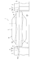
- FIG. 1 is a schematic side view showing an overall configuration of a turbine according to each embodiment of the present invention.
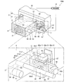
- FIG. 2 is a schematic perspective view showing the configuration of the cooling device for the passenger compartment support portion according to the first embodiment of the present invention, together with an enlarged view of a main portion.
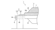
- FIG. 3 is a schematic side view of the main part showing the configuration of a modification of the first embodiment of the present invention.
- FIG. 4 is a schematic perspective view showing the configuration of the cooling device for the passenger compartment support portion according to the second embodiment of the present invention, together with an enlarged view of a main portion and a control block diagram.
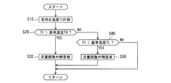
- FIG. 5 is a flowchart for explaining the control according to the second embodiment of the present invention.
- FIG. 1 is a schematic side view showing an overall configuration of a turbine.
- a turbine (rotary machine) 1 includes a rotor (rotary body) 2, a casing (casing) 3 that accommodates the rotor 2, a bearing box (bearing portion) 4 that rotatably supports the rotor 2, and a ground 200.
- a vehicle compartment support portion (hereinafter also referred to as “support portion”) 5 that supports the vehicle compartment 3 is provided.
- the rotor 2 is housed in the passenger compartment 3 in a posture in which the rotation center line (hereinafter also referred to as “rotor rotation center line”) CL is horizontal.
- the rotor 2 is integrally formed by arranging a rotor body (rotating body body) 20 and a pair of rotor shaft ends (rotating shaft ends) 21 provided on both outer sides in the axial direction of the rotor body 20 on the rotor rotation center line CL.
- the rotor main body 20 is accommodated in the passenger compartment 3.
- Each rotor shaft end 21 passes through the casing 3, and the tip end side of each rotor shaft end 21 is exposed to the outside of the casing 3 and supported by the bearing box 4.
- the rotor body 20 is driven by a working fluid (for example, superheated steam or combustion gas) flowing inside the passenger compartment 3 to be given a rotational force, and a generator or a compressor connected via the rotor shaft end 21 by this rotational force. (Both not shown) are driven.
- a working fluid for example, superheated steam or combustion gas
- the vehicle compartment 3 is divided into upper and lower parts, and includes an upper vehicle compartment 30 and a lower vehicle compartment 31.
- the rotor shaft end 21 is drawn out from the passenger compartment 3 on the mating surface of the upper casing 30 and the lower casing 31.
- the support portion 5 is formed from the vicinity of the four corners of the main body of the upper casing 30 or the main body of the lower casing 31, in this embodiment, the main body of the upper casing 30 (hereinafter also referred to as “upper casing main body”) 30 a.
- a projecting portion 50 projecting in the axial direction and a box-shaped support base 51 erected on the ground 200 are provided, and the projecting portion 50 is placed on the upper surface (outer surface of the ceiling wall) 51a1 of the support base 51.
- the protruding portion 50 is called a claw foot because of its shape, and hereinafter, the protruding portion 50 is also referred to as a claw foot 50.
- FIG. 2 is a schematic perspective view showing a configuration of the cooling device 100 for the passenger compartment support portion according to the first embodiment of the present invention, together with an enlarged view of a main portion.
- a bearing surface (sliding contact surface on which the rotor shaft end 21 is slidably contacted) 41 that supports the rotor shaft end 21 of the bearing housing 4 is provided with lubricating oil 6 (not shown in FIG. 1) at a low temperature (for example, about the outside air temperature). (Lubricating fluid) is sequentially supplied.
- the support base 51 has a hollow box shape having a hollow portion 51A, and the lubricating line 6 is supplied to the bearing surface 41 via the hollow portion 51A.
- the lubrication line 6 includes a heat exchanging unit 60 built in the support base 51, an oil supply pipe 61, an oil supply hole 62 drilled in the bearing box 4, and a minute space between the rotor shaft end 21 and the bearing surface 41.
- a clearance 63, an oil drain hole 64 drilled in the bearing box 4, and an oil drain pipe 65 are formed in this order from the upstream side and connected to each other.
- Lubricating oil is supplied to the heat exchanging unit 60 from a lubricating oil supply device (not shown) including a tank, a pump, piping, and the like.
- Lubricating oil has a low temperature, and the cat legs 50 and the supporting base 51 are caused by the lubricating oil flowing through the heat exchanging section 60 by incorporating the heat exchanging section 60 in the supporting base 51 (by passing the lubricating line 6 through the supporting base 51). Can be cooled. That is, the cooling device 100 of the present embodiment is configured by incorporating the heat exchanging unit 60 that forms part of the lubrication line 6 in the bearing box 4. In FIG. 2, for the sake of convenience, the clearance 63 is shown large, and the lubrication line 6 and the cooling device 100 for the support base 5 on the left side in the drawing are omitted.
- the heat exchanging unit 60 includes a plurality of (three in this embodiment) branch pipes 60a (1), 60a (2), 60a (3), and these branch pipes 60a (1), 60a (2), 60a ( 3) includes a set header 60b.
- branch pipes 60a (1), 60a (2), and 60a (3) are not distinguished, they are represented as branch pipes 60a.
- the plurality of branch pipes 60a are arranged in the horizontal direction.
- Each branch pipe 60a has one end (right end in FIG. 2) on the front surface 51b of the support base 51, and an upper end on the horizontal pipe 60a1 connected to the lubricating oil supply device and the other end (left end in FIG. 2) of the horizontal pipe 60a1.
- a horizontal pipe 60a3 having one end (left end in FIG. 2) connected to the lower end of the vertical pipe 60a2. That is, each branch pipe 60 a has a U-turn shape that turns back the hollow portion 51 ⁇ / b> A of the support base 51.
- each branch pipe 60a is disposed at a position close to the upper portion of the ceiling wall inner surface 51a of the support base 51, and is disposed so as to cover substantially the entire lower surface 50a of the claw foot 50 facing upward with the ceiling wall 51a interposed therebetween.
- the horizontal pipe 60a1 and the cat leg 50 exchange heat through the ceiling wall 51a, and the cat leg 50 is entirely cooled from the lower surface 50a by the lubricating oil flowing through the horizontal pipe 60a1.
- the support base 51 is cooled by each branch pipe 60a via the hollow portion 51A or directly.
- each branch pipe 60a into a U-turn shape that is folded back in the hollow portion 51A of the support base 51, the pipe length (flow path length) of each branch pipe 60a can be increased and the heat exchange area can be increased.
- the support base 51 is effectively cooled to suppress thermal expansion, and thermal deformation is suppressed by cooling the support base 51 in a wide range to obtain a uniform temperature distribution.
- each branch pipe 60a3 of each branch pipe 60a is connected to the collective header 60b, and the lubricating oil supplied from each branch pipe 60a to the collective header 60b flows out from the support base 51. And flows to the oil supply pipe 61.
- the other end (the left end in FIG. 2) of the oil supply pipe 61 is connected to an inlet of an oil supply hole 62 drilled in the bearing housing 4, and an outlet of the oil supply hole 62 is between the rotor shaft end 21 and the bearing surface 41. It is connected to the clearance 63. Further, the clearance 63 is connected to an inlet of an oil drain hole 64 drilled in the bearing housing 4, and an outlet of the oil drain hole 64 is connected to an oil drain pipe 65.
- the lubricating oil supplied from the oil supply pipe 61 to the bearing surface 41 through the oil supply hole 62 is discharged from the oil discharge hole 64 through the oil discharge pipe 65.
- a part of the lubrication line 6 for supplying and discharging the lubricating oil to and from the bearing surface 41 is built in the support base 51 as the heat exchange unit 60, thereby circulating the heat exchange unit 60.
- the support part 5 (the cat leg 50 and the support stand 51) can be cooled by the lubricating oil. Therefore, the thermal elongation of the support portion 5 can be suppressed, and the vertical upward displacement of the passenger compartment 3 can be suppressed particularly by suppressing the thermal elongation in the thickness direction.
- the lubricating oil is also used as a cooling medium, it is not necessary to separately prepare a cooling medium for cooling the support base 51 and the claw leg 50, and almost no dedicated equipment for cooling the support portion 5 is required. Therefore, while suppressing an increase in running cost and equipment cost, the support base 51 and the claw leg 50 can be cooled to suppress the thermal elongation and thermal deformation of the support base 51 and the claw leg 50. Moreover, since lubricating oil is supplied to the heat exchanger 60 from the upper part near the cat leg 50 which becomes higher temperature than the support stand 51, the cat leg 50 which becomes high temperature is efficiently cooled by the lowest temperature lubricating oil. Can do.
- the flow rate may be set to increase in this order (flow rate F (1) ⁇ flow rate F (2) ⁇ flow rate F (3)).
- the specific method of setting the flow rate is not limited at all.
- the pipe size may be set so that the inner diameter becomes larger in the order of the branch pipes 60a (1), 60a (2), and 60a (3).
- an orifice may be installed in the branch pipes 60a (1), 60a (2), 60a (3) to adjust the flow rate, or the branch pipes 60a (1), 60a (2), 60a ( An adjustment valve that adjusts each flow rate to 3) may be provided to adjust the flow rate.
- lubricating oil as a cooling medium is flowed relatively large on the high temperature side (root side) and relatively low on the low temperature side (tip side) with respect to the claw paws 50, so that the temperature depends on the temperature.
- the cat paws 50 can be efficiently cooled at a high flow rate, and the temperature of the cat paws 50 can be made uniform and uniform. Thereby, the thermal deformation of the claw leg 50 can be more effectively suppressed.
- FIG. 3 is a schematic side view showing the configuration of this modification (the bearing housing 4 and the rotor shaft end 21 are omitted).
- the heat retaining layer 7 having excellent heat resistance may be provided on the outer peripheral surface exposed to the outside in the upper compartment main body 30 a and the claw foot 50, that is, in a location indicated by a halftone dot in FIG. 3.
- the claw foot 50 has a temperature gradient that becomes lower toward the distal end side, and this temperature gradient can be relaxed by providing the heat retaining layer 7. That is, the temperature distribution from the base of the claw foot 50 to the tip can be flattened.
- the temperature of the support portion 5 is lowered as a whole, the temperature distribution of the support portion 5 is flattened, and the amount of thermal elongation of the support portion 5 itself is reduced, so that the difference in thermal elongation is alleviated. . Also by this, the thermal deformation resulting from the difference in thermal elongation, such as the thermal deformation that is convex on the cat leg 50 or the thermal deformation that is tapered, can be suppressed.
- the provision of the heat retaining layer 7 causes the cat paws 50 to have a high temperature as a whole, and accordingly, the amount of heat transfer from the cat paws 50 to the support base 51 increases, but the support base 51 is cooled by the heat exchanging unit 60.
- the thermal elongation and thermal deformation of the support base 51 can be suppressed.
- the heat exchanging unit 60 is built in the support base 51 and the heat insulating layer 7 is provided on the outer peripheral surface of the upper casing body 30a and the cat leg 50, thereby synergistically increasing the heat extension of the cat leg 50 and the support base 51. Thermal deformation can be suppressed.
- FIG. 4 is a schematic perspective view showing a configuration of a cooling device 100A for a passenger compartment support portion according to a second embodiment of the present invention, together with an enlarged view of a main portion and a control block diagram.
- the clearance 63 is shown large, and the lubrication line 6 and the cooling device 100A for the support base 5 on the left side of the drawing are omitted.
- the cooling device 100A for the vehicle compartment support portion of the present embodiment is that the amount of lubricating oil supplied to the support base 51 (heat exchange portion 60) can be adjusted, the cooling device for the vehicle compartment support portion of the first embodiment. 100 (see FIG. 2).
- the lubricating oil supply device (not shown) is connected to the oil supply pipe 61 ′, and the lubricating oil is first supplied from the lubricating oil supply device to the oil supply pipe 61 ′.
- a branch pipe 66 branched from the oil supply pipe 61 ′ is connected to the center of the distribution header 67 in the extending direction.
- the distribution header 67 extends in the arrangement direction (here, the horizontal direction) of the branch pipes 60a (1), 60a (2), 60a (3), and these branch pipes 60a (1 ), 60a (2), 60a (3) are connected in parallel.
- the outlets of the branch pipes 60a (1), 60a (2), and 60a (3) are connected to the peripheral surface of the collective header 60b, and the outlet of the collective header 60b is connected to the inlet of the merge pipe 68.
- the lubricating oil supplied to the oil supply pipe 61 ′ flows to the branch pipe 66, and then flows to the bearing surface 41 through the heat exchange unit 60, the junction pipe 68, and the oil supply pipe 61 ′ in this order. And what is supplied to the bearing surface 41 by bypassing the heat exchanging section 60 without flowing into the branch pipe 66. That is, in the oil supply pipe 61 ′, a portion between the connection portion of the branch pipe 66 and the connection portion of the junction pipe 68 functions as a bypass flow path (bypass line) 69 that bypasses the heat exchange section 60.
- the branch pipe 66 is provided with a flow rate adjustment valve (distribution adjustment means) 11.
- a flow rate adjustment valve distributed adjustment means
- the opening degree of the flow rate adjusting valve 11 By controlling the opening degree of the flow rate adjusting valve 11, the amount of lubricating oil that flows into the branch pipe 66 and is supplied to the heat exchange unit 60, and lubrication that flows into the bypass channel 69 and bypasses the heat exchange unit 60.
- the distribution ratio with the oil amount is controlled.
- a temperature sensor (temperature detection means) 12 for detecting the temperature of the support base 51 (hereinafter referred to as “support base temperature”) T1 is provided, and the temperature of the support base temperature T1 detected by the temperature sensor 12 is
- a control device 10 is provided that controls the operation of the flow rate adjustment valve 11 to increase the opening degree of the flow rate adjustment valve 11 as the height increases.
- the control device 10 compares the support base temperature T1 detected by the temperature sensor 12 with the reference temperature TH, and if the support base temperature T1 is higher than the reference temperature TH, the flow control valve 11 is opened by a predetermined opening, the amount of lubricating oil supplied to the heat exchanging unit 60 is increased, and the cooling amount of the support base 51 is increased.
- the controller 10 reduces the amount of lubricating oil supplied to the heat exchanging unit 60 by reducing the opening of the flow rate adjustment valve 11 by a predetermined opening. The cooling amount of the support base 51 is reduced.
- the number of times of control for increasing the opening degree of the flow rate adjustment valve 11 until the reference temperature TH is reached increases. Is greatly controlled.
- the opening change amount per one time of the flow rate adjusting valve 11 may be set larger.
- the reference temperature TL is set to a temperature that is lower than the reference temperature TH by ⁇ T [> 0 (zero)], thereby preventing control hunting. Since other configurations are the same as those of the first embodiment, description thereof is omitted.
- step S10 the support table temperature T1 is detected by the temperature sensor 12.
- step S20 the support base temperature T1 is compared with the reference temperature TH. If the support base temperature T1 is higher than the reference temperature TH (T1> TH), the process proceeds to step S30 and the flow rate adjusting valve is reached. While the opening of 11 is increased by a predetermined opening, if the support base temperature T1 is equal to or lower than the reference temperature TH (T1 ⁇ TH), the process proceeds to step S40. In step S40, the support base temperature T1 is compared with the reference temperature TL.
- the process proceeds to step S50 and the flow rate adjustment valve 11 is opened.
- the process returns without changing the opening degree of the flow control valve 11.
- the opening degree of the flow rate adjustment valve 11 increases as the temperature of the support base temperature T1 increases, and the opening degree of the flow rate adjustment valve 11 decreases as the temperature of the support base temperature T1 decreases. Therefore, the amount of the lubricating oil supplied to the claw foot 50 and the support base 51 can be optimized in accordance with the support base temperature T1.
- the heat exchanging unit 60 through which the lubricating oil flows is incorporated in the support base 51 to cool the support base 51, but the present invention is not limited to this aspect.
- a heat exchange part by making a part of pipe
Landscapes
- Engineering & Computer Science (AREA)
- General Engineering & Computer Science (AREA)
- Mechanical Engineering (AREA)
- Chemical & Material Sciences (AREA)
- Combustion & Propulsion (AREA)
- Power Engineering (AREA)
- Mounting Of Bearings Or Others (AREA)
- Motor Or Generator Cooling System (AREA)
- Control Of Turbines (AREA)
Abstract
Description
その一方、タービンの運転中のロータの温度分布は、ロータ回転軸に対して対称である。このため、ロータは、熱伸びしてもロータ回転軸の高さは大きく変位しない。
その結果、タービンの運転中、車室がロータに対して相対的に上方に動き、車室とロータとの間の隙間は、上部で広がり下部で狭まることとなる。
車室の熱変形が大きい場合には、車室とロータとが下部で接触して振動が発生する。熱変形が極端に大きな場合には、車室とロータとが強く接触してこれらの車室とロータとが損傷して、タービンの運転に支障をきたすこともある。
特許文献1(段落[0044]~[0045]及び図4など参照)に開示された技術では、前記支持台に相当する支柱(6)の内部に通路(13)を形成し、この通路(13)内に、空気や水等の冷却流体を流通させて支柱(6)を冷却している。これにより、支柱(6)の熱膨張(熱伸び)を抑え、タービン車室(1)の鉛直上方への変位を抑えている。
したがって、ランニングコストや設備費の増大を抑えつつ、支持部の熱伸び・熱変形を抑制することができる。
以下に示す各実施形態はあくまでも例示に過ぎず、以下の各実施形態で明示しない種々の変形や技術の適用を排除する意図はない。以下の各実施形態の各構成は、それらの趣旨を逸脱しない範囲で種々変形して実施することができると共に、必要に応じて取捨選択することができ、あるいは適宜組み合わせることが可能である。
以下の各実施形態では、本発明をタービンに適用した例を説明する。
[1-1.タービンの全体構成]
以下、図1を参照して本実施形態としてのタービンの全体構成について説明する。
図1は、タービンの全体構成を示す模式的な側面図である。
タービン(回転機械)1は、ロータ(回転体)2と、ロータ2を収容する車室(ケーシング)3と、ロータ2を回転可能に支持する軸受箱(軸受部)4と、地盤200上で車室3を支持する車室支持部(以下「支持部」とも表記する)5と備えている。
ロータ2は、その回転中心線(以下「ロータ回転中心線」とも表記する)CLを水平にした姿勢で車室3内に収容されている。ロータ2は、ロータ本体(回転体本体)20と、ロータ本体20の軸方向両外側に設けられた一対のロータ軸端(回転軸端)21とを、ロータ回転中心線CL上に並べて一体形成されている。
ロータ本体20は車室3の内部に収容されている。各ロータ軸端21は車室3を貫通しており、各ロータ軸端21の先端側は車室3の外部に露出して軸受箱4により支持されている。
ロータ本体20は車室3の内部を流れる作動流体(例えば過熱蒸気や燃焼ガス)によって駆動されて回転力を付与され、この回転力によってロータ軸端21を介して連結された発電機や圧縮機(いずれも図示略)を駆動する。
支持部5は、上車室30の本体又は下車室31の本体、本実施形態では上車室30の本体(以下「上車室本体」とも表記する)30aの四隅近傍からロータ軸端21の軸方向に突出した突出部50と、地盤200上に立設された箱型形状の支持台51とを備えており、支持台51の上面(天井壁外面)51a1に突出部50を載置することで車室3が、支持部5を介して地盤200上に支持される。突出部50はその形状から猫足と呼ばれており、以下、突出部50を猫足50とも表記する。
図2を参照して、軸受箱4及び支持台51についてさらに説明しつつ、本発明の第1実施形態としての車室支持部の冷却装置100を説明する。
図2は、本発明の第1実施形態としての車室支持部の冷却装置100の構成を示す模式的な斜視図を要部拡大図と共に示す図である。
軸受箱4のロータ軸端21を支持する軸受面(ロータ軸端21が摺接する摺接面)41には、潤滑ライン6(図1では省略)により、低温(例えば外気温度程度)の潤滑油(潤滑流体)が順次供給される。支持台51は中空部51Aを有した中空箱型形状をしており、潤滑ライン6はこの中空部51Aを経由して軸受面41に供給される。
潤滑ライン6は、支持台51に内蔵された熱交換部60と、給油管61と、軸受箱4に穿設された給油孔62と、ロータ軸端21と軸受面41との間の微小なクリアランス63と、軸受箱4に穿設された排油孔64と、排油管65とが、上流側からこの順に並べられると共に接続されて形成される。熱交換部60には、タンクやポンプや配管等からなる潤滑油供給装置(図示省略)から潤滑油が供給される。
なお、図2では、便宜的に、クリアランス63を大きく示し、図中左側の支持台5についての潤滑ライン6,冷却装置100を省略している。
複数の枝管60aは水平方向に並べられて設けられている。各枝管60aは、支持台51の正面51bにおいて一端(図2中右端)を、前記潤滑油供給装置に接続された水平管60a1と、水平管60a1の他端(図2中左端)に上端を接続された垂直管60a2と、垂直管60a2の下端に一端(図2中左端)を接続された水平管60a3とを備える。
つまり、各枝管60aは、支持台51の中空部51A内を折り返すUターン形状をしている。
また、各枝管60aを支持台51の中空部51A内で折り返すUターン形状とすることで、各枝管60aの管長(流路長)を長くして熱交換面積を広くとることができる。これにより、支持台51が効果的に冷却されて熱伸びが抑制され、且つ、支持台51を広い範囲で冷却して均等な温度分布とすることにより熱変形が抑制される。
本発明の第1実施形態によれば、軸受面41に潤滑油を供排する潤滑ライン6の一部を、支持台51に熱交換部60として内蔵することで、この熱交換部60を流通する潤滑油により、支持部5(猫足50及び支持台51)を冷却することができる。
したがって、支持部5の熱伸びを抑制することができ、特にその厚み方向への熱伸びを抑制することで、車室3の鉛直上向きの変位を抑制できる。
さらに、潤滑油を冷却媒体として兼用するので、支持台51及び猫足50を冷却するための冷却媒体を別途用意する必要がなく、支持部5を冷却するための専用の設備が殆ど不要となる。
したがって、ランニングコストや設備費の増大を抑えつつ、支持台51及び猫足50を冷却して支持台51及び猫足50の熱伸び・熱変形を抑制することができる。
また、支持台51よりも高温となる猫足50に近い上部から、熱交換器60に潤滑油が供給されるので、最も低温の状態の潤滑油により高温となる猫足50を効率的に冷却することができる。
(1)第1変形例
背景技術の説明の中で上述したように猫足50には先細りとなる熱変形(以下「先細り熱変形」とも表記する)が生じる。この先細り熱変形は、猫足50の根本に近づくほど、つまり図2中右上に位置して上車室本体30aに近くなるほど高温となる(逆の言い方をすれば先端になるほど低温となる)温度勾配が生じることに起因する。
そこで、猫足50の根元に近い枝管60aほど潤滑油が多く流れるようにしてもよい。つまり、枝管60a(1)の潤滑油の流量F(1)、枝管60a(2)の潤滑油の流量F(2)、枝管60a(3)の潤滑油の流量F(3)を、この順に大きくなるように設定してもよい(流量F(1)<流量F(2)<流量F(3))。
この流量設定の具体的な手法は何ら限定されないが、例えば、枝管60a(1),60a(2),60a(3)の順に内径が大きくなるように管サイズを設定してもよい〔枝管60a(1)の内径<枝管60a(2)の内径<枝管60a(3)の内径〕。或いは、枝管60a(1),60a(2),60a(3)内にオリフィスを設置して流量を調整するようにしてもよいし、枝管60a(1),60a(2),60a(3)への各流量を調整する調整弁を設けて流量を調整するようにしてもよい。
本変形例について、図3を参照して説明する。
図3は、本変形例の構成を示す模式的な側面図である(軸受箱4及びロータ軸端21は省略)。
図3に示すように、耐熱性に優れた保温層7を、上車室本体30a及び猫足50において外部に表出する外周面、つまり図3において網点を付した箇所に設けてもよい。
上述したように、猫足50には、先端側ほど低温となる温度勾配があることがわかっており、保温層7を設けることで、この温度勾配を緩和することができる。つまり、猫足50の根元から先端にかけての温度分布を平坦化できる。これは、高温の上車室本体30aから離れているために放熱し易い猫足50の先端側が、保温層7を設けることで当該放熱が抑制されて低温化が抑制されるので、前記温度勾配が緩和されるためである。これにより、前記温度勾配に伴う猫足50の先細り熱変形を抑制することができる。
このように、支持台51に熱交換部60を内蔵すると共に保温層7を上車室本体30aと猫足50との外周面に設けることで、相乗的に猫足50及び支持台51の熱伸び・熱変形を抑制できる。
[2-1.構成]
図4を参照して、本実施形態の車室支持部の冷却装置100Aを説明する。なお、上記第1実施形態と同様の構成要素については同一の符号を付してその説明を省略する。
図4は、本発明の第2実施形態としての車室支持部の冷却装置100Aの構成を示す模式的な斜視図を、要部拡大図及び制御ブロック図と共に示す図である。なお、図4では、便宜的に、クリアランス63を大きく示し、図中左側の支持台5についての潤滑ライン6,冷却装置100Aを省略している。
具体的には、前記潤滑油供給装置(図示省略)が給油管61′に接続されて、前記潤滑油供給装置から潤滑油が先ず給油管61′に供給される。そして、給油管61′から分岐した分岐管66が分配ヘッダ67の延在方向中央に接続される。
分配ヘッダ67は、枝管60a(1),60a(2),60a(3)の並び方向(ここでは水平方向)に延在し、分配ヘッダ67の周面にはこれらの枝管60a(1),60a(2),60a(3)の入口が並列的に接続される。枝管60a(1),60a(2),60a(3)の出口は集合ヘッダ60bの周面に接続され、集合ヘッダ60bの出口は、合流管68の入口に接続され、合流管68の出口は、分岐管66と給油管61′との接続部よりも下流側(軸受面41側)で給油管61′に接続されている。
また、支持台51の温度(以下「支持台温度」と表記する)T1を検出する温度センサ(温度検出手段)12が備えられると共に、この温度センサ12により検出された支持台温度T1の温度が高くなるほど、流量調整弁11の作動を制御して流量調整弁11の開度を大きくする制御装置10が備えられている。
或いは、支持台温度T1から基準温度THを減じた温度差(=T1-TH)が大きいほど、流量調整弁11の一回当たりの開度変更量を大きく設定してもよい。
なお、基準温度TLは、基準温度THよりもΔT〔>0(零)〕だけ低い温度に設定されており、これにより制御のハンチングを防止している。
この他の構成は第1実施形態と同様であるので説明を省略する。
本実施形態では、図5に示すフローチャートに示すように制御が行われる。
先ず、ステップS10において、温度センサ12により支持台温度T1が検出される。
次いで、ステップS20において、この支持台温度T1と基準温度THとの比較が行われ、支持台温度T1が基準温度THよりも高い場合(T1>TH)には、ステップS30に進んで流量調整弁11の開度を所定開度だけ増加する一方、支持台温度T1が基準温度TH以下(T1≦TH)の場合にはステップS40に進む。
ステップS40では、支持台温度T1と基準温度TLとの比較が行われ、支持台温度T1が基準温度TLよりも低い場合(T1<TL)には、ステップS50に進んで流量調整弁11の開度を所定開度だけ減少してリターンする一方、支持台温度T1が基準温度TL以上(T1≧TL)の場合には、流量調整弁11の開度を変更せずにリターンする。
(1)支持台温度T1に替えて、猫足50の温度(以下「猫足温度」と表記する)T2を検出し、猫足温度T2が基準温度THよりも高い場合には、流量調整弁11の開度を大きくし、猫足温度T2が基準温度TLよりも低い場合には、流量調整弁11の開度を小さくするようにしてもよい。
或いは、熱交換部60の入口又は出口における潤滑油の温度TFを計測し、支持台温度T1(又は猫足温度T2)と潤滑油温度TFとの差ΔT(=T1-TF又はT2-TF)が大きいほど流量調整弁11の開度を開くようにしてもよい。
(1)上記各実施形態では、潤滑油が流通する熱交換部60を支持台51に内蔵して支持台51を冷却するようにしたが、この態様に限定されない。例えば、熱交換部を、潤滑ラインを構成する管の一部を猫足50の所定箇所(例えば根元)に接触させることで構成してもよい。或いは、熱交換部を、潤滑ラインを構成する管の一部を、支持台51の外側に巻き付けるなどして支持台51の外面と接触させることで構成してもよい。
2 ロータ(回転体)
3 車室(ケーシング)
4 軸受箱(軸受部)
5 支持部
6 潤滑ライン
7 保温層
10 制御装置
11 流量調整弁(分配調整手段)
12 温度センサ(温度検出手段)
20 ロータ本体(回転体本体)
21 ロータ軸端
30 上車室
30a 上車室30の本体
31 下車室
41 軸受面
50 突出部(猫足)
50a 突出部50の下面
51 支持台
51A 支持台51の中空部
51a1 支持台51の上面(天井壁外面)
51a2 天井壁内面
51b 支持台51の正面
51c 支持台51の側面
60 熱交換部
60a,60a(1),60a(2),60a(3) 熱交換部60の枝管
60a1,60a2 枝管60aの水平管
60a2 垂直管
60a3 水平管
60b 熱交換部60の集合ヘッダ
61,61′ 給油管
62 給油孔
63 クリアランス
64 排油孔
65 排油管
66 分岐管
67 分配ヘッダ
68 合流管
69 バイパス流路(バイパスライン)
100,100A 冷却装置
200 地盤
CL ロータ2の回転中心線
Claims (7)
- 回転体本体及び前記回転体本体の軸方向両外側に固定された一対の回転軸端を有する回転体と、前記回転体本体を収容すると共に前記各回転軸端が貫通するケーシングと、前記回転軸端を回転可能に支持し潤滑ラインから軸受面に潤滑流体が供給される軸受部と、前記ケーシングを支持する支持部とを備えた回転機械において、前記支持部を冷却する、回転機械のケーシング支持部の冷却装置であって、
前記潤滑ラインに、前記潤滑流体と前記支持部とを熱交換させて前記支持部を冷却する熱交換部が設けられている
ことを特徴とする、回転機械のケーシング支持部の冷却装置。 - 前記支持部は、前記ケーシングの本体から突出した突出部と、前記突出部が載置される支持台とを有し、
前記ケーシングの本体の外表面と前記突出部の外表面とに保温層が設けられていることを特徴とする、請求項1に記載の回転機械のケーシング支持部の冷却装置。 - 前記支持部は、前記ケーシングの本体から突出した突出部と、前記突出部が載置される支持台とを有し、
前記熱交換部は前記支持台に内蔵されたことを特徴とする、請求項1又は2に記載の回転機械のケーシング支持部の冷却装置。 - 前記支持部は、前記ケーシングの本体から突出した突出部と、前記突出部が載置される支持台とを有し、
前記熱交換部は、前記突出部の突出方向に沿って並設された複数の枝管を有し、
前記複数の枝管は、前記ケーシングの本体に近いほど前記潤滑流体が多く供給されるように調整がなされた
ことを特徴とする、請求項1~3の何れか一項に記載の回転機械のケーシング支持部の冷却装置。 - 前記潤滑ラインは、前記潤滑流体を、前記熱交換部をバイパスさせて前記軸受面へ供給するバイパスラインを有し、
前記熱交換部をバイパスする前記潤滑流体の流量と、前記熱交換部に供給される前記潤滑流体の流量との分配を調整する分配調整手段と、
前記支持部の温度を検出する温度検出手段と、
前記温度検出手段により検出された温度が高くなるほど、前記熱交換部に供給される前記潤滑流体の流量が多くなるように前記分配調整手段の作動を制御する制御装置とを備えた
ことを特徴とする、請求項1~4の何れか一項に記載の回転機械のケーシング支持部の冷却装置。 - 請求項1~5の何れか一項に記載の回転機械のケーシング支持部の冷却装置を備えた
ことを特徴とする、回転機械。 - 回転体本体及び前記回転体本体の軸方向両外側に固定された一対の回転軸端を有する回転体と、前記回転体本体を収容すると共に前記各回転軸端が貫通するケーシングと、前記回転軸端を回転可能に支持し潤滑ラインから軸受面に潤滑流体が供給される軸受部と、前記ケーシングを支持する支持部とを備えた回転機械において、前記支持部を冷却する、回転機械のケーシング支持部の冷却方法であって、
前記潤滑流体と前記支持部とを熱交換させて前記支持部を冷却する
ことを特徴とする、回転機械のケーシング支持部の冷却方法。
Priority Applications (4)
| Application Number | Priority Date | Filing Date | Title |
|---|---|---|---|
| KR1020187026960A KR102133733B1 (ko) | 2016-03-25 | 2016-11-15 | 회전 기계의 케이싱 지지부의 냉각 장치 및 회전 기계, 그리고 회전 기계의 케이싱 지지부의 냉각 방법 |
| CN201680083801.6A CN109072718B (zh) | 2016-03-25 | 2016-11-15 | 旋转机械的壳体支承部的冷却装置及冷却方法、旋转机械 |
| US16/086,754 US11111817B2 (en) | 2016-03-25 | 2016-11-15 | Cooling device for casing support part of rotary machine, rotary machine, and cooling method for casing support part of rotary machine |
| DE112016006655.4T DE112016006655T5 (de) | 2016-03-25 | 2016-11-15 | Kühlvorrichtung für Gehäusestützelement einer Rotationsmaschine, eine Rotationsmaschine und ein Kühlverfahren für ein Gehäusestützelement einer Rotationsmaschine |
Applications Claiming Priority (2)
| Application Number | Priority Date | Filing Date | Title |
|---|---|---|---|
| JP2016061918A JP6649147B2 (ja) | 2016-03-25 | 2016-03-25 | 回転機械のケーシング支持部の冷却装置及び回転機械、並びに回転機械のケーシング支持部の冷却方法 |
| JP2016-061918 | 2016-03-25 |
Publications (1)
| Publication Number | Publication Date |
|---|---|
| WO2017163482A1 true WO2017163482A1 (ja) | 2017-09-28 |
Family
ID=59901024
Family Applications (1)
| Application Number | Title | Priority Date | Filing Date |
|---|---|---|---|
| PCT/JP2016/083772 Ceased WO2017163482A1 (ja) | 2016-03-25 | 2016-11-15 | 回転機械のケーシング支持部の冷却装置及び回転機械、並びに回転機械のケーシング支持部の冷却方法 |
Country Status (6)
| Country | Link |
|---|---|
| US (1) | US11111817B2 (ja) |
| JP (1) | JP6649147B2 (ja) |
| KR (1) | KR102133733B1 (ja) |
| CN (1) | CN109072718B (ja) |
| DE (1) | DE112016006655T5 (ja) |
| WO (1) | WO2017163482A1 (ja) |
Families Citing this family (3)
| Publication number | Priority date | Publication date | Assignee | Title |
|---|---|---|---|---|
| JP7300944B2 (ja) * | 2019-09-11 | 2023-06-30 | 三菱重工業株式会社 | 蒸気タービン |
| US11976855B2 (en) * | 2019-11-13 | 2024-05-07 | Samsung Electronics Co., Ltd. | Heat exchanger and air conditioner having the same |
| JP7390963B2 (ja) * | 2020-04-20 | 2023-12-04 | 三菱重工コンプレッサ株式会社 | 吊り具、支持治具、回転機械の分解方法、及び回転機械の組立方法 |
Citations (3)
| Publication number | Priority date | Publication date | Assignee | Title |
|---|---|---|---|---|
| JP2007009731A (ja) * | 2005-06-28 | 2007-01-18 | Mitsubishi Heavy Ind Ltd | タービン |
| JP2011033002A (ja) * | 2009-08-05 | 2011-02-17 | Mitsubishi Heavy Ind Ltd | 軸受箱 |
| JP2012159051A (ja) * | 2011-02-02 | 2012-08-23 | Mitsubishi Heavy Ind Ltd | ターボ回転機械の車室支持構造 |
Family Cites Families (15)
| Publication number | Priority date | Publication date | Assignee | Title |
|---|---|---|---|---|
| GB1014015A (en) * | 1964-04-02 | 1965-12-22 | Rolls Royce | Improvements in or relating to bearing lubricating means |
| US7387189B2 (en) * | 2003-08-14 | 2008-06-17 | United Technologies Corp. | Emergency lubrication system |
| JP4410651B2 (ja) | 2004-10-06 | 2010-02-03 | 三菱重工業株式会社 | タービン及びタービン製造方法 |
| JP2007051574A (ja) * | 2005-08-17 | 2007-03-01 | Hitachi Ltd | タービン軸受装置 |
| CN100472042C (zh) * | 2005-10-08 | 2009-03-25 | 张志远 | 双轮正圆转子发动机 |
| TWI303289B (en) * | 2006-03-31 | 2008-11-21 | Delta Electronics Inc | Fan, bearing structure and sleeve bearing thereof |
| US8152446B2 (en) | 2007-08-23 | 2012-04-10 | General Electric Company | Apparatus and method for reducing eccentricity and out-of-roundness in turbines |
| JP5159702B2 (ja) | 2009-05-20 | 2013-03-13 | 株式会社東芝 | 蒸気タービン |
| US20120195750A1 (en) * | 2011-01-31 | 2012-08-02 | General Electric Company | Turbomachine supports having thermal control system |
| JP5570544B2 (ja) * | 2012-02-29 | 2014-08-13 | 株式会社日立製作所 | すべり軸受装置 |
| FR2992703B1 (fr) * | 2012-06-27 | 2015-01-30 | Snecma | Palier a moyen de lubrification et systeme pour changer le pas des pales d'une helice de turbopropulseur d'aeronef, equipe dudit palier |
| US9376934B2 (en) * | 2012-08-24 | 2016-06-28 | General Electric Company | Cooling circuit for reducing thermal growth differential of turbine rotor and shell supports |
| CN104065236B (zh) * | 2013-03-22 | 2017-05-03 | 林英楠 | 可无级调节磁场强度的永磁调速、制动或负载装置 |
| JP2015175246A (ja) | 2014-03-13 | 2015-10-05 | 三菱日立パワーシステムズ株式会社 | 車室支持構造、車室、タービン |
| US9695705B2 (en) * | 2014-10-29 | 2017-07-04 | General Electric Company | Systems and methods for controlling rotor to stator clearances in a steam turbine |
-
2016
- 2016-03-25 JP JP2016061918A patent/JP6649147B2/ja not_active Expired - Fee Related
- 2016-11-15 WO PCT/JP2016/083772 patent/WO2017163482A1/ja not_active Ceased
- 2016-11-15 DE DE112016006655.4T patent/DE112016006655T5/de active Pending
- 2016-11-15 US US16/086,754 patent/US11111817B2/en active Active
- 2016-11-15 CN CN201680083801.6A patent/CN109072718B/zh not_active Expired - Fee Related
- 2016-11-15 KR KR1020187026960A patent/KR102133733B1/ko active Active
Patent Citations (3)
| Publication number | Priority date | Publication date | Assignee | Title |
|---|---|---|---|---|
| JP2007009731A (ja) * | 2005-06-28 | 2007-01-18 | Mitsubishi Heavy Ind Ltd | タービン |
| JP2011033002A (ja) * | 2009-08-05 | 2011-02-17 | Mitsubishi Heavy Ind Ltd | 軸受箱 |
| JP2012159051A (ja) * | 2011-02-02 | 2012-08-23 | Mitsubishi Heavy Ind Ltd | ターボ回転機械の車室支持構造 |
Also Published As
| Publication number | Publication date |
|---|---|
| KR102133733B1 (ko) | 2020-07-14 |
| DE112016006655T5 (de) | 2018-12-13 |
| CN109072718A (zh) | 2018-12-21 |
| US20190048741A1 (en) | 2019-02-14 |
| CN109072718B (zh) | 2021-04-20 |
| JP6649147B2 (ja) | 2020-02-19 |
| JP2017172549A (ja) | 2017-09-28 |
| KR20180112040A (ko) | 2018-10-11 |
| US11111817B2 (en) | 2021-09-07 |
Similar Documents
| Publication | Publication Date | Title |
|---|---|---|
| KR101928791B1 (ko) | 열 조절 시스템을 갖는 직접 구동 풍력 터빈 | |
| JP4950367B1 (ja) | 再生エネルギー型発電装置 | |
| CN106050425B (zh) | 用于燃气涡轮发动机的传热装置和设备 | |
| RU2351766C2 (ru) | Паровая турбина и способ работы паровой турбины | |
| JP5511982B2 (ja) | 冷却システムを有する直接駆動型風車および直接駆動型風車を制御する方法 | |
| JP2017198204A (ja) | ヒートパイプを使用してオイルリザーバ及び出口ガイドベーンを熱的に統合するためのシステム及び方法 | |
| AU2015271163B2 (en) | Pod propulsion device and a method for cooling such | |
| JP6649147B2 (ja) | 回転機械のケーシング支持部の冷却装置及び回転機械、並びに回転機械のケーシング支持部の冷却方法 | |
| JP2009250214A (ja) | 風力発電装置用ファン装置および風力発電装置 | |
| JP2006112499A (ja) | ティルティングパッド型軸受 | |
| JP2014177937A (ja) | 冷却ユニットを有するタービン・エンジン用ケーシング | |
| JP2012244659A (ja) | 回転電機のステータ構造 | |
| JP2018066362A (ja) | 蒸気タービン及び温度制御方法 | |
| US8878403B2 (en) | Air-cooled motor-generator and method for operating a motor-generator | |
| JP5518687B2 (ja) | 回転電機のスラスト軸受装置 | |
| JP5973483B2 (ja) | 閉鎖循環冷媒の冷却装置 | |
| CN106460562B (zh) | 燃气轮机排气系统 | |
| JP2017025901A (ja) | 熱エネルギー回収装置及びその起動方法 | |
| CN106679242A (zh) | 冷凝器的制冷剂出口装置 | |
| US4237854A (en) | Damper construction and a method of cooling a damper | |
| JP2000170638A (ja) | 回転機械の閉鎖循環式冷却装置 | |
| KR20200012302A (ko) | 냉매 안정화 시스템 및 그 제어방법 | |
| JP2023008563A (ja) | 廃熱発電システム | |
| JP2012193715A (ja) | 発電装置 | |
| JP2022044146A (ja) | 熱音響装置 |
Legal Events
| Date | Code | Title | Description |
|---|---|---|---|
| ENP | Entry into the national phase |
Ref document number: 20187026960 Country of ref document: KR Kind code of ref document: A |
|
| WWE | Wipo information: entry into national phase |
Ref document number: 1020187026960 Country of ref document: KR |
|
| 121 | Ep: the epo has been informed by wipo that ep was designated in this application |
Ref document number: 16895505 Country of ref document: EP Kind code of ref document: A1 |
|
| 122 | Ep: pct application non-entry in european phase |
Ref document number: 16895505 Country of ref document: EP Kind code of ref document: A1 |