WO2017159426A1 - Work unit and work device - Google Patents
Work unit and work device Download PDFInfo
- Publication number
- WO2017159426A1 WO2017159426A1 PCT/JP2017/008753 JP2017008753W WO2017159426A1 WO 2017159426 A1 WO2017159426 A1 WO 2017159426A1 JP 2017008753 W JP2017008753 W JP 2017008753W WO 2017159426 A1 WO2017159426 A1 WO 2017159426A1
- Authority
- WO
- WIPO (PCT)
- Prior art keywords
- work
- tool
- rotation
- rotation mechanism
- axis
- Prior art date
Links
Images


Classifications
-
- H—ELECTRICITY
- H02—GENERATION; CONVERSION OR DISTRIBUTION OF ELECTRIC POWER
- H02K—DYNAMO-ELECTRIC MACHINES
- H02K7/00—Arrangements for handling mechanical energy structurally associated with dynamo-electric machines, e.g. structural association with mechanical driving motors or auxiliary dynamo-electric machines
- H02K7/10—Structural association with clutches, brakes, gears, pulleys or mechanical starters
- H02K7/116—Structural association with clutches, brakes, gears, pulleys or mechanical starters with gears
-
- B—PERFORMING OPERATIONS; TRANSPORTING
- B25—HAND TOOLS; PORTABLE POWER-DRIVEN TOOLS; MANIPULATORS
- B25J—MANIPULATORS; CHAMBERS PROVIDED WITH MANIPULATION DEVICES
- B25J9/00—Programme-controlled manipulators
- B25J9/02—Programme-controlled manipulators characterised by movement of the arms, e.g. cartesian coordinate type
-
- B—PERFORMING OPERATIONS; TRANSPORTING
- B23—MACHINE TOOLS; METAL-WORKING NOT OTHERWISE PROVIDED FOR
- B23P—METAL-WORKING NOT OTHERWISE PROVIDED FOR; COMBINED OPERATIONS; UNIVERSAL MACHINE TOOLS
- B23P19/00—Machines for simply fitting together or separating metal parts or objects, or metal and non-metal parts, whether or not involving some deformation; Tools or devices therefor so far as not provided for in other classes
- B23P19/04—Machines for simply fitting together or separating metal parts or objects, or metal and non-metal parts, whether or not involving some deformation; Tools or devices therefor so far as not provided for in other classes for assembling or disassembling parts
-
- B—PERFORMING OPERATIONS; TRANSPORTING
- B23—MACHINE TOOLS; METAL-WORKING NOT OTHERWISE PROVIDED FOR
- B23Q—DETAILS, COMPONENTS, OR ACCESSORIES FOR MACHINE TOOLS, e.g. ARRANGEMENTS FOR COPYING OR CONTROLLING; MACHINE TOOLS IN GENERAL CHARACTERISED BY THE CONSTRUCTION OF PARTICULAR DETAILS OR COMPONENTS; COMBINATIONS OR ASSOCIATIONS OF METAL-WORKING MACHINES, NOT DIRECTED TO A PARTICULAR RESULT
- B23Q1/00—Members which are comprised in the general build-up of a form of machine, particularly relatively large fixed members
- B23Q1/0009—Energy-transferring means or control lines for movable machine parts; Control panels or boxes; Control parts
-
- B—PERFORMING OPERATIONS; TRANSPORTING
- B23—MACHINE TOOLS; METAL-WORKING NOT OTHERWISE PROVIDED FOR
- B23Q—DETAILS, COMPONENTS, OR ACCESSORIES FOR MACHINE TOOLS, e.g. ARRANGEMENTS FOR COPYING OR CONTROLLING; MACHINE TOOLS IN GENERAL CHARACTERISED BY THE CONSTRUCTION OF PARTICULAR DETAILS OR COMPONENTS; COMBINATIONS OR ASSOCIATIONS OF METAL-WORKING MACHINES, NOT DIRECTED TO A PARTICULAR RESULT
- B23Q1/00—Members which are comprised in the general build-up of a form of machine, particularly relatively large fixed members
- B23Q1/01—Frames, beds, pillars or like members; Arrangement of ways
- B23Q1/012—Portals
-
- B—PERFORMING OPERATIONS; TRANSPORTING
- B23—MACHINE TOOLS; METAL-WORKING NOT OTHERWISE PROVIDED FOR
- B23Q—DETAILS, COMPONENTS, OR ACCESSORIES FOR MACHINE TOOLS, e.g. ARRANGEMENTS FOR COPYING OR CONTROLLING; MACHINE TOOLS IN GENERAL CHARACTERISED BY THE CONSTRUCTION OF PARTICULAR DETAILS OR COMPONENTS; COMBINATIONS OR ASSOCIATIONS OF METAL-WORKING MACHINES, NOT DIRECTED TO A PARTICULAR RESULT
- B23Q1/00—Members which are comprised in the general build-up of a form of machine, particularly relatively large fixed members
- B23Q1/25—Movable or adjustable work or tool supports
- B23Q1/44—Movable or adjustable work or tool supports using particular mechanisms
- B23Q1/50—Movable or adjustable work or tool supports using particular mechanisms with rotating pairs only, the rotating pairs being the first two elements of the mechanism
- B23Q1/54—Movable or adjustable work or tool supports using particular mechanisms with rotating pairs only, the rotating pairs being the first two elements of the mechanism two rotating pairs only
- B23Q1/5406—Movable or adjustable work or tool supports using particular mechanisms with rotating pairs only, the rotating pairs being the first two elements of the mechanism two rotating pairs only a single rotating pair followed perpendicularly by a single rotating pair
-
- B—PERFORMING OPERATIONS; TRANSPORTING
- B23—MACHINE TOOLS; METAL-WORKING NOT OTHERWISE PROVIDED FOR
- B23Q—DETAILS, COMPONENTS, OR ACCESSORIES FOR MACHINE TOOLS, e.g. ARRANGEMENTS FOR COPYING OR CONTROLLING; MACHINE TOOLS IN GENERAL CHARACTERISED BY THE CONSTRUCTION OF PARTICULAR DETAILS OR COMPONENTS; COMBINATIONS OR ASSOCIATIONS OF METAL-WORKING MACHINES, NOT DIRECTED TO A PARTICULAR RESULT
- B23Q5/00—Driving or feeding mechanisms; Control arrangements therefor
- B23Q5/02—Driving main working members
- B23Q5/04—Driving main working members rotary shafts, e.g. working-spindles
- B23Q5/10—Driving main working members rotary shafts, e.g. working-spindles driven essentially by electrical means
-
- B—PERFORMING OPERATIONS; TRANSPORTING
- B25—HAND TOOLS; PORTABLE POWER-DRIVEN TOOLS; MANIPULATORS
- B25J—MANIPULATORS; CHAMBERS PROVIDED WITH MANIPULATION DEVICES
- B25J17/00—Joints
- B25J17/02—Wrist joints
- B25J17/0258—Two-dimensional joints
-
- B—PERFORMING OPERATIONS; TRANSPORTING
- B25—HAND TOOLS; PORTABLE POWER-DRIVEN TOOLS; MANIPULATORS
- B25J—MANIPULATORS; CHAMBERS PROVIDED WITH MANIPULATION DEVICES
- B25J17/00—Joints
- B25J17/02—Wrist joints
- B25J17/0258—Two-dimensional joints
- B25J17/0266—Two-dimensional joints comprising more than two actuating or connecting rods
-
- B—PERFORMING OPERATIONS; TRANSPORTING
- B25—HAND TOOLS; PORTABLE POWER-DRIVEN TOOLS; MANIPULATORS
- B25J—MANIPULATORS; CHAMBERS PROVIDED WITH MANIPULATION DEVICES
- B25J19/00—Accessories fitted to manipulators, e.g. for monitoring, for viewing; Safety devices combined with or specially adapted for use in connection with manipulators
- B25J19/0025—Means for supplying energy to the end effector
- B25J19/0029—Means for supplying energy to the end effector arranged within the different robot elements
-
- B—PERFORMING OPERATIONS; TRANSPORTING
- B25—HAND TOOLS; PORTABLE POWER-DRIVEN TOOLS; MANIPULATORS
- B25J—MANIPULATORS; CHAMBERS PROVIDED WITH MANIPULATION DEVICES
- B25J9/00—Programme-controlled manipulators
- B25J9/02—Programme-controlled manipulators characterised by movement of the arms, e.g. cartesian coordinate type
- B25J9/023—Cartesian coordinate type
- B25J9/026—Gantry-type
-
- B—PERFORMING OPERATIONS; TRANSPORTING
- B25—HAND TOOLS; PORTABLE POWER-DRIVEN TOOLS; MANIPULATORS
- B25J—MANIPULATORS; CHAMBERS PROVIDED WITH MANIPULATION DEVICES
- B25J9/00—Programme-controlled manipulators
- B25J9/10—Programme-controlled manipulators characterised by positioning means for manipulator elements
- B25J9/104—Programme-controlled manipulators characterised by positioning means for manipulator elements with cables, chains or ribbons
-
- H—ELECTRICITY
- H02—GENERATION; CONVERSION OR DISTRIBUTION OF ELECTRIC POWER
- H02K—DYNAMO-ELECTRIC MACHINES
- H02K37/00—Motors with rotor rotating step by step and without interrupter or commutator driven by the rotor, e.g. stepping motors
- H02K37/24—Structural association with auxiliary mechanical devices
-
- B—PERFORMING OPERATIONS; TRANSPORTING
- B23—MACHINE TOOLS; METAL-WORKING NOT OTHERWISE PROVIDED FOR
- B23Q—DETAILS, COMPONENTS, OR ACCESSORIES FOR MACHINE TOOLS, e.g. ARRANGEMENTS FOR COPYING OR CONTROLLING; MACHINE TOOLS IN GENERAL CHARACTERISED BY THE CONSTRUCTION OF PARTICULAR DETAILS OR COMPONENTS; COMBINATIONS OR ASSOCIATIONS OF METAL-WORKING MACHINES, NOT DIRECTED TO A PARTICULAR RESULT
- B23Q1/00—Members which are comprised in the general build-up of a form of machine, particularly relatively large fixed members
- B23Q1/25—Movable or adjustable work or tool supports
- B23Q1/44—Movable or adjustable work or tool supports using particular mechanisms
- B23Q1/50—Movable or adjustable work or tool supports using particular mechanisms with rotating pairs only, the rotating pairs being the first two elements of the mechanism
- B23Q1/54—Movable or adjustable work or tool supports using particular mechanisms with rotating pairs only, the rotating pairs being the first two elements of the mechanism two rotating pairs only
- B23Q1/545—Movable or adjustable work or tool supports using particular mechanisms with rotating pairs only, the rotating pairs being the first two elements of the mechanism two rotating pairs only comprising spherical surfaces
- B23Q1/5462—Movable or adjustable work or tool supports using particular mechanisms with rotating pairs only, the rotating pairs being the first two elements of the mechanism two rotating pairs only comprising spherical surfaces with one supplementary sliding pair
-
- Y—GENERAL TAGGING OF NEW TECHNOLOGICAL DEVELOPMENTS; GENERAL TAGGING OF CROSS-SECTIONAL TECHNOLOGIES SPANNING OVER SEVERAL SECTIONS OF THE IPC; TECHNICAL SUBJECTS COVERED BY FORMER USPC CROSS-REFERENCE ART COLLECTIONS [XRACs] AND DIGESTS
- Y10—TECHNICAL SUBJECTS COVERED BY FORMER USPC
- Y10T—TECHNICAL SUBJECTS COVERED BY FORMER US CLASSIFICATION
- Y10T409/00—Gear cutting, milling, or planing
- Y10T409/30—Milling
- Y10T409/30784—Milling including means to adustably position cutter
- Y10T409/308512—Compound angular adjustment
Definitions
- the present invention relates to a work unit and a work device.
- Patent Document 1 discloses a tip unit including a tool rotation mechanism that rotates a work tool in a horizontal direction and a tool movement mechanism that moves the tool to a predetermined vertical angle, and the tip unit is placed at a predetermined position in a work area.
- a work robot is described that includes an orthogonal movement mechanism that moves a work position of a placed work and a work rotation mechanism that holds the work and rotates it horizontally.
- Patent Document 2 discloses a tip unit including a tool rotation mechanism that rotates a work tool in a horizontal direction and a tool movement mechanism that moves the tool to a predetermined vertical angle, and the tip unit is placed at a predetermined position in the work area.
- a working robot is described.
- Patent Document 3 describes a working robot provided with a working tool for deburring a workpiece on a vertical articulated robot.
- the apparatus described in Patent Document 1 is horizontal for a workpiece stopped at a predetermined position. Work from a direction different from the direction cannot be performed.
- the apparatus described in Patent Document 2 further includes a horizontal rotation mechanism that places a work on a rotary table that can be rotated in the horizontal direction and rotationally drives the rotary table, thereby rotating and moving multi-directional surfaces of the work. Are moved to the work position so that work can be performed on multi-directional surfaces of the workpiece.
- a large moving mechanism is required, and the apparatus becomes large.
- Patent Document 3 is configured to perform work by attaching a work tool to the tip of a vertical articulated robot, but each work arm is positioned on a work surface far from the base of the robot. Requires a larger vertical articulated robot than necessary.
- an object of the present invention is to provide a work unit and a work device that efficiently work from multiple directions on a work placed in a preset work area.
- a tool rotation mechanism for rotating the tool, and the tool rotation mechanism around a first axis.
- a first rotation mechanism that rotates, and a second rotation mechanism that rotates the tool rotation mechanism and the first rotation mechanism around a second axis that is orthogonal to the first axis
- the first rotation mechanism includes a stator connected to the second rotation mechanism, and a rotor provided inside the stator.
- the tool rotation mechanism includes a main body portion connected to the rotor, and the main body.
- a working unit is provided, comprising: a rotating body that is mounted on the unit and rotates the tool; and a drive transmission unit that transmits a rotational driving force to the rotating body.
- the work unit a plane moving mechanism for moving the work unit in a predetermined plane set in the work space, and the work unit set in the work space.
- a working device comprising a vertical movement mechanism that moves in a vertical plane orthogonal to a predetermined plane.
- Explanatory drawing of the working device in one Embodiment of this invention Explanatory drawing which shows the working range of the working apparatus of FIG. 1A.
- work unit of FIG. 3 is an explanatory perspective view of the work unit in FIG. 2.
- FIG. 3 is an explanatory perspective view of the work unit in FIG. 2.
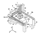
- FIG. 1A is a perspective view of a work apparatus A including a work unit 100 according to an embodiment of the present invention.
- arrows X and Y indicate two directions that are horizontal and orthogonal to each other, and an arrow Z indicates a vertical direction.
- the work apparatus A is perpendicular to a plane moving mechanism 1 that moves the work unit 100 in a predetermined plane set in a work space WS, which will be described later, and a predetermined plane set in the work space WS.
- a vertical movement mechanism 2 that moves in a vertical plane.
- the plane moving mechanism 1 includes a plane guide portion 20 that guides the movement of the vertical moving mechanism 2.
- the planar guide portion 20 includes a first planar guide portion 20a extending in the X direction and a pair of second planar guide portions 20b extending in the Y direction.
- the first planar guide portion 20a includes a first frame member 20a1 provided with a guide portion (not shown) that guides the movement of the vertical movement mechanism 2 and extending in the X direction.
- the pair of second planar guide portions 20b includes a pair of second frame members 20b1 each provided with a guide portion (not shown) that guides the movement of the first frame member 20a1 and extending in the Y direction.
- the pair of second frame members 20b1 are arranged in parallel with an interval in the X direction.
- the plane moving mechanism 1 includes a first moving mechanism 21 that moves the vertical moving mechanism 2 in the X direction and a second moving mechanism 22 that moves in the Y direction.
- the first moving mechanism 21 includes a first moving body 21a that moves along the guide of the first planar guide portion 20a, and a first drive mechanism (not shown) that moves the first moving body 21a.
- the vertical moving mechanism 2 is moved in the X direction by being configured by the first moving body 21a.
- the second moving mechanism 22 includes a pair of second moving bodies 22a1 that move along the guides of the pair of second planar guide portions 20b, and a second drive mechanism (not shown) that moves the second moving bodies 22a1.
- the first moving mechanism 21 is moved in the Y direction by being supported by the second moving body 22a1, and the vertical moving mechanism 2 is moved between the pair of second frame members 20b1 by the first moving mechanism 21 and the second moving mechanism 22. You can move between.
- the vertical moving mechanism 2 includes a vertical frame member vf that is supported by the first moving body 21a so as to be movable up and down and moves in the Z direction, and a vertical drive mechanism (not shown) that moves the vertical frame member vf in the Z direction. Further, a work unit 100 described later is configured at the lower end of the vertical frame member vf.
- the first moving mechanism 21, the second moving mechanism 22, and the vertical moving mechanism 2 can be exemplified by adopting a slider that employs a ball screw mechanism, for example, but is not limited thereto.
- Examples of the moving mechanism include a rack-pinion mechanism, a nut-ball screw mechanism, or a belt transmission mechanism using a motor or the like as a drive source.
- the work apparatus A further includes a column portion 23 that supports the planar guide portion 20 so that the work unit 100 can be moved in the work space.
- the struts 23 are arranged at four locations so as to form four corners on the lower surfaces of the pair of second moving mechanisms 22.
- the work device A forms a work space WS in a region below the flat guide part 20 and defined by the support parts 23 at the four corners.
- a placement unit 3 for placing and holding the workpiece W is disposed in the work space WS.
- a workpiece W is disposed on the placement unit 3.
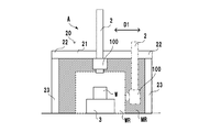
- FIG. 1B shows an explanatory diagram for explaining the work range in the work space WS of the work device A as seen from the arrow B in FIG. 1A.
- an area defined by a work range indicated by a chain line so as to surround the placement unit 3 and the workpiece W is shown as a work effective range WR.
- a range surrounded by diagonal lines in the drawing is shown as a tool movement range MR.
- the work effective range WR is a range in which the work unit 100 moved in the tool movement range MR by the first moving mechanism 21, the second moving mechanism 22, and the vertical moving mechanism 2 can perform work on the work W. Show.
- the work unit 100 can perform work on the work placed on the placement unit 3 as long as the work is within a work effective range WR.
- the work effective range WR is described as a range surrounded by a chain line for the sake of explanation.
- the first moving mechanism 21 prevents the work W, the placement unit 3 and the work unit 100 from interfering with each other.
- the operation unit 100 is moved by controlling the operation of the second moving mechanism 22 and the vertical moving mechanism 2, and can be arbitrarily moved within the range of the work space WS.
- the work unit 100 is moved in the tool movement range MR by the plane guide unit 20 and the vertical movement mechanism 2, and is positioned by rotating the tool T toward the workpiece W by a rotation mechanism described later. Thereby, in the work space WS, the work unit 100 can access the work W from all directions except the part of the placement unit 3 and can perform work.
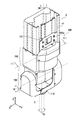
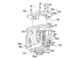
- FIG. 2 shows a partial perspective view of the work unit 100.
- the work unit 100 shown in FIG. 2 shows a state where it is attached to the lower end of the vertical movement mechanism 2.
- the work unit 100 is attached to the lower end of the vertical frame member vf in the vertical movement mechanism 2 located at the upper side in the drawing via the attachment portion 101.
- the work unit 100 is attached immediately below the vertical movement mechanism 2 in the Z direction.
- the rotation axis TA of the tool T which will be described later, and the center position of the Z axis of the vertical movement mechanism 2 in the XY plane can be configured coaxially.
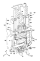
- the work unit 100 includes a tool rotation mechanism 110 on which a tool T (indicated by a two-dot chain line) for performing work on a work W arranged in the work space WS is rotatably mounted, and a tool rotation mechanism 110 having a first tool rotation mechanism 110.
- the first rotation mechanism 120 that rotates about the axis 1A is provided.
- the first shaft 1A extends in a direction parallel to the X direction in FIG. 2, and is a shaft for rotating the tool T in the YZ plane by the first rotation mechanism 120.
- the work unit 100 includes a second rotation mechanism 130 that rotates the tool rotation mechanism 110 and the first rotation mechanism 120 around a second axis 2A orthogonal to the first axis 1A.
- the second shaft 2A is a shaft that extends in a direction parallel to the Z direction in FIG. 2 and rotates the first rotation mechanism 120 and the tool T within the XY plane by the second rotation mechanism 130.
- the tool rotation mechanism 110 rotates the tool T around the rotation axis TA of the tool extending in the Z direction in FIG.
- FIG. 3 is a schematic sectional view taken along line III-III in FIG. 4A and 4B are perspective views of the first rotation mechanism 120 and the second rotation mechanism 130.
- FIG. 3 the vertical frame vf of the vertical mechanism 2 and the exterior parts of the second rotation mechanism 130 shown in FIG. 2 are not shown.
- 4A and 4B show a state where the exterior parts are removed from the work unit 100 shown in FIG. 4A is a perspective view seen from one side, and FIG. 4B is a perspective view seen from the other side.
- the second rotation mechanism 130 includes a turntable 131 that supports the first turn mechanism 120, a second rotation drive source 132 that rotates the turntable 131 around the second axis 2A, and a second rotation drive source 132. And a support 133 to be supported.
- the turntable 131 includes a rotation connection portion 131a connected to the speed reducer 132a and a connection portion 131b that fixes and supports a stator 121 described later. Further, the turntable 131 includes an arm support portion 131c that is connected and supported by the rotation connection portion 131a and that is rotatably connected to the other arm portion 123b described later.
- the second rotation drive source 132 is supported by the support 133 and is connected to the turntable 131 via a speed reducer 132a (detailed mechanism is not shown).
- the reduction gear 132a the reduction gear using a gear can be illustrated, for example, However, It is not limited to this, You may use a trochoid reduction gear.
- the support body 133 includes a support portion 133a connected to the attachment portion 101 attached to the lower end portion of the vertical frame vf, and a motor housing portion 133b connected to the support portion 133a and housing the second rotation drive source 132.
- the motor housing portion 133b is a cylindrical member, and a support portion (not shown) that supports the second rotation drive source 132 is formed therein.
- the support 133 includes an accommodation support part 1342 that forms a part of the accommodation part 134 described later, and is configured around the outer periphery of the support 133.
- the support body 133 includes a cover support portion 101a that supports the cover of the vertical frame vf of the vertical movement mechanism 2 on the support portion 133a.
- the second rotation mechanism 130 includes an accommodating portion 134 that is accommodated when a cable C described later is connected to the first rotation mechanism 120 from the vertical frame vf through the support 133 and the turntable 131.
- the housing part 134 is connected to the turntable 131 so as to surround the outer periphery of the motor housing part 133 b, and moves together with the turntable 131 to form a part of the housing part 134, and the support body 133.
- an accommodation support part 1342 that is connected to the outer periphery of the motor accommodation part 133 b and forms a part of the accommodation part 134.
- the accommodating part 134 is configured such that a part of the accommodating rotating part 1341 and the accommodating support part 1342 are overlapped, and the accommodating rotating part 1341 is configured to be rotatable relative to the accommodating support part 1342.
- the first rotation mechanism 120 includes a stator 121 connected to the second rotation mechanism 130 and a rotor 122 provided inside the stator 121.
- the stator 121 is fixed to the turntable 131 of the second turning mechanism 130 and is rotated integrally with the turntable 131.
- the stator 121 is a cylindrical member arranged so that its longitudinal direction extends in the X direction in FIG.
- the rotor 122 is a hollow shaft-like member that is rotatably disposed on the inner peripheral side of the stator 121 with the first shaft 1A as a central axis.
- a cable C which will be described later, is disposed in the hollow interior of the rotor 122 so as to be inserted therethrough. Therefore, the stator 121 and the rotor 122 constitute a hollow motor in which the rotor 122 rotates relative to the stator 121.
- the second rotating body 123 that holds the tool rotating mechanism 110 is fixed to the rotor 122.
- Second rotating body 123 includes one arm portion 123a connected to one end portion of rotor 122 (the right end portion in the X direction in the drawing).
- one arm portion 123a is provided with a connecting arm portion 1231 connected to one end portion of the rotor 122 and a tool rotating mechanism 110 described later on the other, and a tool support provided in parallel with the first shaft 1A.
- Arm part 123a2 is provided.
- the second rotating body 123 is provided on the other end portion side (left side in the X direction in the drawing) of the rotor 122, and is connected to the arm support portion 131c so as to be rotatable, the one arm portion 123a and the other arm portion 123a.
- the 2nd rotary body 123 is not limited to the said form,
- the other arm part 123b may be connected with the rotor 122.
- the cable C for supplying power or the like to the tool rotating mechanism 110 can be wired in the rotor 122.
- a cable C from a rotation drive source 113a of the tool rotation mechanism 110 to be described later is wired from one arm portion 123a side, passes through the inside of the rotor 122, and comes out to the other arm portion 123b side. It is wired in the accommodation space 134a of the upper accommodation part 134.
- a round cable can be adopted as the cable C.
- the cable C extending from the first rotation mechanism 120 is wired in the main section 134a from a position indicated by C1 in the drawing (a rotation communication portion formed on the turntable 131), and is drawn in two stages in the accommodation space 134a. After being rotated, it is wired to a vertical frame vf of the vertical movement mechanism 2 (not shown) through a portion indicated by C2 in the drawing (a support communication portion formed on the support base 133).
- a round cable wiring in a small space becomes possible, and even when the turntable 131 rotates 360 degrees or more with respect to the support part 133, the cable C can be routed and disconnection can be prevented.
- the one arm portion 123a is connected to the communication portion 123a1 provided in the connection arm portion 1231 so that the cable (wiring) C connected to the tool rotation mechanism 110 can be routed through the hollow portion of the rotor 122. Is provided. By doing so, the routing of the cable C can be improved, and the work unit 100 can be reduced in size and weight and the dead space can be reduced.
- the main body 111 is fixed to the lower surface of the tool support arm 123 a 2 of the second rotating body 123.
- the rotating body 112 is held by the main body 111 so as to be relatively rotatable, and can be rotated around the rotation axis TA of the tool.
- the rotating body 112 is rotated by a rotational driving force supplied from a rotational driving source 113a, which will be described later, of the drive transmission unit 113, whereby the mounted tool is rotated. Further, the rotating body 112 includes a tool mounting portion of the tool T (not shown).
- the drive transmission unit 113 includes a rotation drive source 113a that supplies a rotation drive force, and a transmission mechanism 113b that transmits the rotation drive force from the rotation drive source 113a to the rotating body 122.
- the rotational drive source 113a is disposed on a drive support portion 123d provided adjacent (offset) to the extending direction side of the first shaft 1A in the one arm portion 123a of the second rotating body 123.
- the rotation drive source 113a has its drive rotation axis 113a1 offset in parallel to the tool rotation axis TA and in the extension direction of the first axis 1A (the radial direction of the tool rotation axis) with respect to the tool rotation axis TA. Provided.
- the tool rotation mechanism 110 and the rotation drive source 113a that rotates the tool rotation mechanism 110 are not directly connected in the vertical direction (Z-axis direction) but are connected via the transmission mechanism 113b.
- the rotary body in the first rotation mechanism 120 is not connected to the first rotation mechanism 120 in the state of FIG.
- a rotational drive source 113 a is connected to 122.
- the second shaft 2A of the second rotation mechanism 130 and the drive rotation shaft 113a1 of the rotation drive source 113a are not concentric, and the drive rotation shaft 113a1 is relative to the second shaft 2A. Offset placement in the extension direction.
- the tool rotation mechanism 110 is coupled to the offset rotation drive shaft 113a1 via the transmission mechanism 113b.
- the tool rotation axis TA in the tool rotation mechanism 110 is arranged so as to be concentric with the second axis 2A.
- the tool mounting portion of the rotating body 122 from the lower end of the vertical frame member vf of the vertical moving mechanism 2 is compared with the case where the second shaft 2A, the drive rotating shaft 113a1, and the tool rotating shaft TA are arranged concentrically. Can be shortened. Therefore, the work in the work range in the predetermined work area can be performed efficiently.
- the transmission mechanism 113b can exemplify a belt transmission mechanism in the present embodiment.
- the belt transmission mechanism includes a driving pulley 113b1 fixed to the driving rotating shaft 113a1 of the rotation driving source 113a, a driven pulley 113b2 fixed to the rotating body 122, a driving pulley 113b1 and a driven pulley 113b2.
- the drive belt 113b3 is wound around. Therefore, the rotational driving force of the rotational driving source 113a is transmitted to the tool via the driving rotating shaft 113a1, the driving pulley 113b1, the driving belt 113b3, the driven pulley 113b2, and the rotating body 122.
- the transmission mechanism 113b is not limited to the belt transmission mechanism, and may adopt a form in which a plurality of gears are connected to transmit the driving force, a form in which the driving force is transmitted using a drive shaft, or the like.
- the extension line of the rotation axis TA of the tool passes through the intersection of the first axis 1A of the first rotation mechanism 120 and the extension line of the second axis 2A of the second rotation mechanism 130. That is, even when the tool is rotated around the first axis 1A by the first rotation mechanism 120, the distance from the first axis 1A to the tool does not change. Further, even when the first rotation mechanism 120 is rotated by the second rotation mechanism 130, the distance from the second shaft 2A to the tool does not change. Therefore, the position of the tool can be accurately grasped.
- FIG. 6 is a block diagram of a control unit 500 that controls the work device A of the present embodiment.
- the control unit 500 includes a processing unit 510, a storage unit 520, and an interface unit 530, which are connected to each other via a bus (not shown).
- the processing unit 510 executes the program stored in the storage unit 520.
- the processing unit 510 is a CPU, for example.
- the storage unit 520 is, for example, a RAM, a ROM, a hard disk, or the like.
- the interface unit 530 is provided between the processing unit 510 and an external device (host computer 540, input device (for example, sensor) 550, output device (for example, actuator of each driving mechanism) 560). Or an I / O interface.
- the vertical movement is achieved by matching the Z-axis axis 2A of the vertical movement mechanism 2 with the Z-axis axis TA of the working unit 100.
- the moment rigidity between the mechanism 2 and the work unit 100 is improved, and the weight that can be transported by the work unit 100 can be improved.
- the cable routing is improved, and the work unit 100 can be made lighter and more compact.
- the tool rotation axis TA in the tool rotation mechanism 110 is provided concentrically with the Z-axis axis 2A of the vertical movement mechanism 2, the drive rotation axis 113a1 of the rotation drive source 113a in the tool rotation mechanism 110 is concentric.
- the tool rotation mechanism 110 is coupled to the rotation drive source 113a via the transmission mechanism 113b.
- the distance from the lower end of the vertical frame member vf of the vertical movement mechanism 2 to the tool mounting portion of the rotating body 122 can be shortened, so that the work range in the work area can be effectively utilized.
- the housing portion 134 to hold the cable C, even if the first rotation mechanism 120 is rotated by the second rotation mechanism 130, disconnection of the cable C in the first rotation mechanism 120 can be prevented.
Abstract
Provided are a work unit and a work device that are able to efficiently perform work from multiple directions with respect to a workpiece disposed in a predetermined work area. This work unit is mounted with a tool (T) that performs work on a workpiece disposed within a predetermined work space, and is provided with: a tool rotating mechanism (110) which rotates the tool; a first turning mechanism (120) which turns the tool rotating mechanism about a first axis; and a second turning mechanism (130) which turns the tool rotating mechanism and the first turning mechanism about a second axis that is orthogonal to the first axis, wherein the first turning mechanism is provided with a stator (121) connected to the second turning mechanism and a rotor (122) disposed inside the stator, and the tool rotating mechanism is provided with a main body (111) connected to the rotor, with a rotary body (112) that is mounted to the main body and rotates the tool, and with a drive transmission part (113) that transmits a rotational driving force to the rotary body.
Description
本発明は、作業ユニット及び作業装置に関する。
The present invention relates to a work unit and a work device.
作業エリア内の載置位置に配置された作業対象となるワークに対して所定の作業(例えば、加工、組立、計測など)を行うツールを移動させ、作業に最適な角度に作業ツールを位置づけて作業を行う作業用ロボットがある。
Move the tool that performs a predetermined work (for example, machining, assembly, measurement, etc.) to the work target work placed at the placement position in the work area, and position the work tool at the optimum angle for the work There is a working robot that performs work.
特許文献1には、作業ツールを水平方向に回転するツール回転機構と、ツールを所定の垂直角度に移動するツール移動機構と、を含む先端ユニットと、先端ユニットを作業エリア内の所定の位置に配置されたワークの作業位置に移動させる直交移動機構と、ワークを保持し水平方向に回動させるワーク回動機構と、を備えた作業用ロボットが記載されている。
Patent Document 1 discloses a tip unit including a tool rotation mechanism that rotates a work tool in a horizontal direction and a tool movement mechanism that moves the tool to a predetermined vertical angle, and the tip unit is placed at a predetermined position in a work area. A work robot is described that includes an orthogonal movement mechanism that moves a work position of a placed work and a work rotation mechanism that holds the work and rotates it horizontally.
また特許文献2には、作業ツールを水平方向に回転するツール回転機構と、ツールを所定の垂直角度に移動するツール移動機構と、を含む先端ユニットと、先端ユニットを作業エリアの所定の位置に配置されたワークの上下方向の作業位置に移動させる昇降移動機構と、所定の位置に載置されたワークを作業エリアの所定の高さ位置の平面内を移動させる水平移動機構と、を備えた作業用ロボットが記載されている。
Further, Patent Document 2 discloses a tip unit including a tool rotation mechanism that rotates a work tool in a horizontal direction and a tool movement mechanism that moves the tool to a predetermined vertical angle, and the tip unit is placed at a predetermined position in the work area. An up-and-down movement mechanism for moving the arranged work to a work position in the vertical direction, and a horizontal movement mechanism for moving the work placed at a predetermined position in a plane at a predetermined height position of the work area. A working robot is described.
そして、特許文献3には、垂直多関節ロボットにワークのバリ取りを行う作業用のツールを備えた作業用ロボットが記載されている。
Patent Document 3 describes a working robot provided with a working tool for deburring a workpiece on a vertical articulated robot.
しかし特許文献1に記載の装置は、先端ユニットが水平方向と平行な水平軸周りの作業ツールの回動と、ツールの水平回転しかできないため、所定の位置に停止したワークに対しては、水平方向と異なる方向からの作業を行うことができない。
However, since the tip unit can only rotate the work tool around the horizontal axis parallel to the horizontal direction and rotate the tool horizontally, the apparatus described in Patent Document 1 is horizontal for a workpiece stopped at a predetermined position. Work from a direction different from the direction cannot be performed.
そこで特許文献2に記載の装置は、更に水平方向に回転可能な回転テーブル上にワークを載置し、回転テーブルを回転駆動させる水平回転機構を備えることでワークの多方向の面を回転移動させて作業位置に移動させ、ワークの多方向の面に対して作業をできるようにしている。しかし、重量の重いワークや大きいワークを移動させるには、大きな移動機構が必要となり、装置が大がかりになってしまう。
In view of this, the apparatus described in Patent Document 2 further includes a horizontal rotation mechanism that places a work on a rotary table that can be rotated in the horizontal direction and rotationally drives the rotary table, thereby rotating and moving multi-directional surfaces of the work. Are moved to the work position so that work can be performed on multi-directional surfaces of the workpiece. However, in order to move a heavy workpiece or a large workpiece, a large moving mechanism is required, and the apparatus becomes large.
特許文献3に記載の装置は、垂直多関節ロボットの先端に作業ツールを装着させて作業をおこなうようにしているが、ロボットの土台から遠い位置のワークの作業面に対しては、それぞれのアームが干渉する可能性があるため必要以上に大きな垂直多関節ロボットが必要となる。
The apparatus described in Patent Document 3 is configured to perform work by attaching a work tool to the tip of a vertical articulated robot, but each work arm is positioned on a work surface far from the base of the robot. Requires a larger vertical articulated robot than necessary.
従って、本発明の目的は、予め設定された作業エリアに配置されたワークに対して多方向から効率よく作業を行う作業ユニット及び作業装置を提供することにある。
Therefore, an object of the present invention is to provide a work unit and a work device that efficiently work from multiple directions on a work placed in a preset work area.
本発明によれば、作業空間内に配置されたワークに対して作業を行うツールが装着された作業ユニットにおいて、前記ツールを回転させるツール回転機構と、前記ツール回転機構を第1の軸周りに回動させる第1回動機構と、前記ツール回転機構及び前記第1回動機構を前記第1の軸と直交する第2の軸周りに回動させる第2回動機構と、を備え、前記第1回動機構は、前記第2回動機構に接続されるステータと、該ステータの内側に設けられるロータとを備え、前記ツール回転機構は、前記ロータに接続される本体部と、前記本体部に装着され、前記ツールを回転させる回転体と、該回転体に回転駆動力を伝達する駆動伝達部とを備えることを特徴とする作業ユニットが提供される。
According to the present invention, in a work unit in which a tool for performing work on a work placed in a work space is mounted, a tool rotation mechanism for rotating the tool, and the tool rotation mechanism around a first axis. A first rotation mechanism that rotates, and a second rotation mechanism that rotates the tool rotation mechanism and the first rotation mechanism around a second axis that is orthogonal to the first axis, The first rotation mechanism includes a stator connected to the second rotation mechanism, and a rotor provided inside the stator. The tool rotation mechanism includes a main body portion connected to the rotor, and the main body. A working unit is provided, comprising: a rotating body that is mounted on the unit and rotates the tool; and a drive transmission unit that transmits a rotational driving force to the rotating body.
また、本発明によれば、前記作業ユニットと、前記作業ユニットを前記作業空間内に設定された所定の平面内で移動させる平面移動機構と、前記作業ユニットを前記作業空間内に設定された前記所定の平面と直交する垂直面内で移動させる垂直移動機構と、を備えたことを特徴とする作業装置が提供される。
According to the present invention, the work unit, a plane moving mechanism for moving the work unit in a predetermined plane set in the work space, and the work unit set in the work space. There is provided a working device comprising a vertical movement mechanism that moves in a vertical plane orthogonal to a predetermined plane.
本発明によれば、予め設定された作業エリアに配置されたワークに対して多方向から効率よく作業を行うことができる。
According to the present invention, it is possible to efficiently work from multiple directions on a work placed in a preset work area.
以下、本発明の例示的な実施形態について図面を参照して説明する。なお、各図において、同じ参照符号は、同様の要素を示し、紙面に対する上下左右方向を、本実施形態における装置または部材の上下左右方向として、本文中の説明の際に用いることとする。
Hereinafter, exemplary embodiments of the present invention will be described with reference to the drawings. In each figure, the same reference numerals indicate the same elements, and the vertical and horizontal directions with respect to the paper surface are used as the vertical and horizontal directions of the device or member in the present embodiment in the description in the text.
図1Aは本発明の一実施形態に係る作業ユニット100を含む作業装置Aの斜視図である。図1A中、矢印X及びYは水平方向であって互いに直交する2方向を示し、矢印Zは垂直方向を示す。作業装置Aは、作業ユニット100を後述する作業空間WS内に設定された所定の平面内で移動させる平面移動機構1と、作業ユニット100を作業空間WS内に設定された所定の平面と直交する垂直面内で移動させる垂直移動機構2とを備える。平面移動機構1は、垂直移動機構2の移動をガイドする平面ガイド部20を含む。
FIG. 1A is a perspective view of a work apparatus A including a work unit 100 according to an embodiment of the present invention. In FIG. 1A, arrows X and Y indicate two directions that are horizontal and orthogonal to each other, and an arrow Z indicates a vertical direction. The work apparatus A is perpendicular to a plane moving mechanism 1 that moves the work unit 100 in a predetermined plane set in a work space WS, which will be described later, and a predetermined plane set in the work space WS. And a vertical movement mechanism 2 that moves in a vertical plane. The plane moving mechanism 1 includes a plane guide portion 20 that guides the movement of the vertical moving mechanism 2.
平面ガイド部20は、X方向に延びる第1平面ガイド部20aおよびY方向に延びる一対の第2平面ガイド部20bを含む。第1平面ガイド部20aは、垂直移動機構2の移動をガイドする不図示のガイド部が設けられ、X方向に延びる第1フレーム部材20a1を含む。一対の第2平面ガイド部20bは、第1フレーム部材20a1の移動をガイドする不図示のガイド部がそれぞれ設けられ、Y方向に延びる一対の第2フレーム部材20b1を含む。一対の第2フレーム部材20b1は、X方向に間隔を空けて平行に配置される。
The planar guide portion 20 includes a first planar guide portion 20a extending in the X direction and a pair of second planar guide portions 20b extending in the Y direction. The first planar guide portion 20a includes a first frame member 20a1 provided with a guide portion (not shown) that guides the movement of the vertical movement mechanism 2 and extending in the X direction. The pair of second planar guide portions 20b includes a pair of second frame members 20b1 each provided with a guide portion (not shown) that guides the movement of the first frame member 20a1 and extending in the Y direction. The pair of second frame members 20b1 are arranged in parallel with an interval in the X direction.
平面移動機構1は、垂直移動機構2をX方向に移動させる第1移動機構21およびY方向に移動させる第2移動機構22を含む。第1移動機構21は、第1平面ガイド部20aのガイドに沿って移動する第1移動体21aと、第1移動体21aを移動させる不図示の第1駆動機構とを備える。垂直移動機構2は、第1移動体21aに構成されることでX方向へ移動される。第2移動機構22は、一対の第2平面ガイド部20bのガイドに沿って移動する一対の第2移動体22a1と、第2移動体22a1を移動させる不図示の第2駆動機構とを備える。第1移動機構21は、第2移動体22a1に支持されることでY方向へ移動され、垂直移動機構2は、第1移動機構21および第2移動機構22によって一対の第2フレーム部材20b1の間を移動することができる。
The plane moving mechanism 1 includes a first moving mechanism 21 that moves the vertical moving mechanism 2 in the X direction and a second moving mechanism 22 that moves in the Y direction. The first moving mechanism 21 includes a first moving body 21a that moves along the guide of the first planar guide portion 20a, and a first drive mechanism (not shown) that moves the first moving body 21a. The vertical moving mechanism 2 is moved in the X direction by being configured by the first moving body 21a. The second moving mechanism 22 includes a pair of second moving bodies 22a1 that move along the guides of the pair of second planar guide portions 20b, and a second drive mechanism (not shown) that moves the second moving bodies 22a1. The first moving mechanism 21 is moved in the Y direction by being supported by the second moving body 22a1, and the vertical moving mechanism 2 is moved between the pair of second frame members 20b1 by the first moving mechanism 21 and the second moving mechanism 22. You can move between.
垂直移動機構2は、第1移動体21aに昇降可能に支持され、Z方向に移動する垂直フレーム部材vfと、垂直フレーム部材vfをZ方向に移動させる不図示の垂直駆動機構とを備える。また、垂直フレーム部材vfの下端には、後述する作業ユニット100が構成される。
The vertical moving mechanism 2 includes a vertical frame member vf that is supported by the first moving body 21a so as to be movable up and down and moves in the Z direction, and a vertical drive mechanism (not shown) that moves the vertical frame member vf in the Z direction. Further, a work unit 100 described later is configured at the lower end of the vertical frame member vf.
第1移動機構21、第2移動機構22、垂直移動機構2は、例えばボールねじ機構を採用したスライダを採用することが例示できるが、これに限定されない。移動機構として、例えば、モータ等を駆動源とした、ラック-ピニオン機構、ナット-ボールネジ機構、若しくはベルト伝動機構を例示することができる。
The first moving mechanism 21, the second moving mechanism 22, and the vertical moving mechanism 2 can be exemplified by adopting a slider that employs a ball screw mechanism, for example, but is not limited thereto. Examples of the moving mechanism include a rack-pinion mechanism, a nut-ball screw mechanism, or a belt transmission mechanism using a motor or the like as a drive source.
作業装置Aは、作業ユニット100を作業空間内で移動可能に平面ガイド部20を支持する支柱部23を更に備える。支柱部23は、一対の第2移動機構22の下面に四隅を形成するように4か所に配置されている。作業装置Aは、平面ガイド部20の下方であって、四隅の支柱部23によって区画された領域に作業空間WSを形成する。作業空間WS内にはワークWを載置保持する載置ユニット3が配置される。載置ユニット3上には、ワークWが配置される。
The work apparatus A further includes a column portion 23 that supports the planar guide portion 20 so that the work unit 100 can be moved in the work space. The struts 23 are arranged at four locations so as to form four corners on the lower surfaces of the pair of second moving mechanisms 22. The work device A forms a work space WS in a region below the flat guide part 20 and defined by the support parts 23 at the four corners. A placement unit 3 for placing and holding the workpiece W is disposed in the work space WS. A workpiece W is disposed on the placement unit 3.
図1Bに図1Aにおける矢印Bからみた作業装置Aの作業空間WS内における作業範囲を説明する説明図を示す。図1Bには、載置ユニット3及びワークWを囲むようにして鎖線で示した作業範囲によって規定される領域を作業有効範囲WRとして示す。またその外側で図中斜線で囲む範囲をツール移動範囲MRとして示す。作業有効範囲WRは、第1移動機構21、第2移動機構22、垂直移動機構2によってツール移動範囲MR内を移動した作業ユニット100が、ワークWに対して作業を行うことが可能な範囲を示す。したがって作業ユニット100は、ワークが作業有効範囲WR内に存在する大きさであれば、載置ユニット3に載置されたワークに対して、作業を行うことができる。なお、本実施例においては、説明のため作業有効範囲WRを鎖線で囲んだ範囲として説明しているが、ワークWおよび載置ユニット3と作業ユニット100とが干渉しないように第1移動機構21、第2移動機構22、垂直移動機構2を動作制御させて作業ユニット100を移動させることで、作業空間WSの範囲内を任意に移動可能である。
FIG. 1B shows an explanatory diagram for explaining the work range in the work space WS of the work device A as seen from the arrow B in FIG. 1A. In FIG. 1B, an area defined by a work range indicated by a chain line so as to surround the placement unit 3 and the workpiece W is shown as a work effective range WR. In addition, a range surrounded by diagonal lines in the drawing is shown as a tool movement range MR. The work effective range WR is a range in which the work unit 100 moved in the tool movement range MR by the first moving mechanism 21, the second moving mechanism 22, and the vertical moving mechanism 2 can perform work on the work W. Show. Accordingly, the work unit 100 can perform work on the work placed on the placement unit 3 as long as the work is within a work effective range WR. In the present embodiment, the work effective range WR is described as a range surrounded by a chain line for the sake of explanation. However, the first moving mechanism 21 prevents the work W, the placement unit 3 and the work unit 100 from interfering with each other. The operation unit 100 is moved by controlling the operation of the second moving mechanism 22 and the vertical moving mechanism 2, and can be arbitrarily moved within the range of the work space WS.
作業ユニット100は、平面ガイド部20及び垂直移動機構2によって、ツール移動範囲MR内を移動され、後述する回動機構によりツールTをワークWの方へ向けて回動させ、位置づけられる。これにより、作業空間WS内において、作業ユニット100はワークWに対して、載置ユニット3の部分を除く全方向からアクセス可能であり、作業を行うことができる。
The work unit 100 is moved in the tool movement range MR by the plane guide unit 20 and the vertical movement mechanism 2, and is positioned by rotating the tool T toward the workpiece W by a rotation mechanism described later. Thereby, in the work space WS, the work unit 100 can access the work W from all directions except the part of the placement unit 3 and can perform work.
図2に作業ユニット100の部分斜視図を示す。図2に示す作業ユニット100は、垂直移動機構2の下端に取り付けられた状態を示している。作業ユニット100は、図中上方に位置する垂直移動機構2における垂直フレーム部材vfの下端に取付部101を介して取り付けられる。なお作業ユニット100は、垂直移動機構2のZ方向直下に取り付けられている。これにより、後述するツールTの回転軸TAと垂直移動機構2のZ軸のX-Y平面における中心位置とを同軸に構成することができる。
FIG. 2 shows a partial perspective view of the work unit 100. The work unit 100 shown in FIG. 2 shows a state where it is attached to the lower end of the vertical movement mechanism 2. The work unit 100 is attached to the lower end of the vertical frame member vf in the vertical movement mechanism 2 located at the upper side in the drawing via the attachment portion 101. The work unit 100 is attached immediately below the vertical movement mechanism 2 in the Z direction. Thereby, the rotation axis TA of the tool T, which will be described later, and the center position of the Z axis of the vertical movement mechanism 2 in the XY plane can be configured coaxially.
作業ユニット100は、作業空間WS内に配置されたワークWに対して作業を行うツールT(二点鎖線で示す)が回転自在に装着されるツール回転機構110と、ツール回転機構110を第1の軸1A周りに回動させる第1回動機構120を備える。第1の軸1Aは、図2においてX方向と平行な方向に延び、第1回動機構120によってツールTをY-Z平面内で回動させる軸である。
The work unit 100 includes a tool rotation mechanism 110 on which a tool T (indicated by a two-dot chain line) for performing work on a work W arranged in the work space WS is rotatably mounted, and a tool rotation mechanism 110 having a first tool rotation mechanism 110. The first rotation mechanism 120 that rotates about the axis 1A is provided. The first shaft 1A extends in a direction parallel to the X direction in FIG. 2, and is a shaft for rotating the tool T in the YZ plane by the first rotation mechanism 120.
さらに作業ユニット100は、ツール回転機構110及び第1回動機構120を第1の軸1Aと直交する第2の軸2A周りに回動させる第2回動機構130とを備える。第2の軸2Aは、図2においてZ方向と平行な方向に延び、第2回動機構130によって第1回動機構120及びツールTをX-Y平面内で回動させる軸である。ツール回転機構110は、図2においてZ方向に延びるツールの回転軸TA周りにツールTを回転させる。
Further, the work unit 100 includes a second rotation mechanism 130 that rotates the tool rotation mechanism 110 and the first rotation mechanism 120 around a second axis 2A orthogonal to the first axis 1A. The second shaft 2A is a shaft that extends in a direction parallel to the Z direction in FIG. 2 and rotates the first rotation mechanism 120 and the tool T within the XY plane by the second rotation mechanism 130. The tool rotation mechanism 110 rotates the tool T around the rotation axis TA of the tool extending in the Z direction in FIG.
図3に図2におけるIII-III概略断面図を示す。図4Aおよび図4Bに第1回動機構120及び第2回動機構130の斜視図を示す。図3において、図2で示した垂直機構2の垂直フレームvf及び第2回動機構130の外装部品は、その図示を省略している。図4Aおよび図4Bは、図2に示す作業ユニット100において外装部品を取り外した状態を示す。図4Aは一方側から見た斜視図であり、図4Bは他方側から見た斜視図である。
FIG. 3 is a schematic sectional view taken along line III-III in FIG. 4A and 4B are perspective views of the first rotation mechanism 120 and the second rotation mechanism 130. FIG. In FIG. 3, the vertical frame vf of the vertical mechanism 2 and the exterior parts of the second rotation mechanism 130 shown in FIG. 2 are not shown. 4A and 4B show a state where the exterior parts are removed from the work unit 100 shown in FIG. 4A is a perspective view seen from one side, and FIG. 4B is a perspective view seen from the other side.
<第2回動機構130>
第2回動機構130は、第1回動機構120を支持する回転台131と、回転台131を第2の軸2A周りに回転させる第2回転駆動源132と、第2回転駆動源132を支持する支持体133とを備える。 <Second rotation mechanism 130>
Thesecond rotation mechanism 130 includes a turntable 131 that supports the first turn mechanism 120, a second rotation drive source 132 that rotates the turntable 131 around the second axis 2A, and a second rotation drive source 132. And a support 133 to be supported.
第2回動機構130は、第1回動機構120を支持する回転台131と、回転台131を第2の軸2A周りに回転させる第2回転駆動源132と、第2回転駆動源132を支持する支持体133とを備える。 <
The
図3、図4Aおよび図4Bに示すように回転台131は、減速機132aに接続される回転接続部131aと、後述するステータ121を固定支持する接続部131bとを備える。また、回転台131は、回転接続部131aに接続支持されると共に後述する他方アーム部123bが回転可能に接続されるアーム支持部131cを備える。第2回転駆動源132は、支持体133に支持され、減速機132a(詳細な機構の図示は省略)を介して回転台131と連結される。なお、減速機132aとしては、例えば歯車を用いた減速機を例示できるが、これに限定されず、トロコイド減速機等を用いてもよい。
As shown in FIGS. 3, 4A, and 4B, the turntable 131 includes a rotation connection portion 131a connected to the speed reducer 132a and a connection portion 131b that fixes and supports a stator 121 described later. Further, the turntable 131 includes an arm support portion 131c that is connected and supported by the rotation connection portion 131a and that is rotatably connected to the other arm portion 123b described later. The second rotation drive source 132 is supported by the support 133 and is connected to the turntable 131 via a speed reducer 132a (detailed mechanism is not shown). In addition, as the reduction gear 132a, the reduction gear using a gear can be illustrated, for example, However, It is not limited to this, You may use a trochoid reduction gear.
支持体133は、垂直フレームvfの下端部に取り付けられる取付部101に接続される支持部133aと、支持部133aに接続され、第2回転駆動源132を収容するモータ収容部133bとを備える。本実施例においてモータ収容部133bは、円筒状の部材であり、その内部に第2回転駆動源132を支持する不図示の支持部が構成される。また、支持体133は、後述する収容部134の一部を形成する収容支持部1342が支持体133の外周周囲に構成される。また、支持体133は、支持部133aに垂直移動機構2の垂直フレームvfのカバーを支持するカバー支持部101aを備える。
The support body 133 includes a support portion 133a connected to the attachment portion 101 attached to the lower end portion of the vertical frame vf, and a motor housing portion 133b connected to the support portion 133a and housing the second rotation drive source 132. In the present embodiment, the motor housing portion 133b is a cylindrical member, and a support portion (not shown) that supports the second rotation drive source 132 is formed therein. In addition, the support 133 includes an accommodation support part 1342 that forms a part of the accommodation part 134 described later, and is configured around the outer periphery of the support 133. In addition, the support body 133 includes a cover support portion 101a that supports the cover of the vertical frame vf of the vertical movement mechanism 2 on the support portion 133a.
また、第2回動機構130は、後述するケーブルCが垂直フレームvfから支持体133および回転台131を通って、第1回動機構120へ接続される際に収容される収容部134を備える。収容部134は、モータ収容部133bの外周を囲むように回転台131に接続され、回転台131と共に移動し収容部134の一部を形成する筒状の収容回転部1341と、支持体133のモータ収容部133bの外周に接続され、収容部134の一部を形成する収容支持部1342と、を含む。また、収容部134は、収容回転部1341および収容支持部1342の一部が重複して配置され、収容回転部1341が収容支持部1342に対して相対的に回転可能に構成される。
Further, the second rotation mechanism 130 includes an accommodating portion 134 that is accommodated when a cable C described later is connected to the first rotation mechanism 120 from the vertical frame vf through the support 133 and the turntable 131. . The housing part 134 is connected to the turntable 131 so as to surround the outer periphery of the motor housing part 133 b, and moves together with the turntable 131 to form a part of the housing part 134, and the support body 133. And an accommodation support part 1342 that is connected to the outer periphery of the motor accommodation part 133 b and forms a part of the accommodation part 134. In addition, the accommodating part 134 is configured such that a part of the accommodating rotating part 1341 and the accommodating support part 1342 are overlapped, and the accommodating rotating part 1341 is configured to be rotatable relative to the accommodating support part 1342.
<第1回動機構120>
第1回動機構120は、第2回動機構130に接続されるステータ121と、ステータ121の内側に設けられるロータ122とを備える。ステータ121は、第2回動機構130の回転台131に固定され、回転台131と一体に回転される。ステータ121は、図3においてその長手方向がX方向へ延びるように配置される筒状部材である。 <First rotation mechanism 120>
Thefirst rotation mechanism 120 includes a stator 121 connected to the second rotation mechanism 130 and a rotor 122 provided inside the stator 121. The stator 121 is fixed to the turntable 131 of the second turning mechanism 130 and is rotated integrally with the turntable 131. The stator 121 is a cylindrical member arranged so that its longitudinal direction extends in the X direction in FIG.
第1回動機構120は、第2回動機構130に接続されるステータ121と、ステータ121の内側に設けられるロータ122とを備える。ステータ121は、第2回動機構130の回転台131に固定され、回転台131と一体に回転される。ステータ121は、図3においてその長手方向がX方向へ延びるように配置される筒状部材である。 <
The
ロータ122は、ステータ121の内周側に第1の軸1Aを中心軸として回転可能に配置された中空軸状の部材である。ロータ122の中空内部には、後述するケーブルCが挿通可能に配置される。したがってステータ121とロータ122とは、ロータ122がステータ121に対して相対回転する中空モータを構成する。
The rotor 122 is a hollow shaft-like member that is rotatably disposed on the inner peripheral side of the stator 121 with the first shaft 1A as a central axis. A cable C, which will be described later, is disposed in the hollow interior of the rotor 122 so as to be inserted therethrough. Therefore, the stator 121 and the rotor 122 constitute a hollow motor in which the rotor 122 rotates relative to the stator 121.
ロータ122には、ツール回転機構110を保持する第2回転体123が固定される。第2回転体123は、ロータ122の一方端部(図中X方向右側端部)に連結される一方アーム部123aを含む。一方アーム部123aは、その一方がロータ122の一方端部に接続される接続アーム部1231と、他方に後述するツール回転機構110が設けられ、第1の軸1Aと平行に設けられたツール支持アーム部123a2を備える。また、第2回転体123は、ロータ122の他方端部側(図中X方向左側)に設けられ、アーム支持部131cに回転可能に連結される他方アーム部123bと、一方アーム部123a及び他方アーム部123bを連結するアーム連結部123cとを備える。なお第2回転体123は、上記形態に限定されず、例えば他方アーム部123bがロータ122に連結されてもよい。
The second rotating body 123 that holds the tool rotating mechanism 110 is fixed to the rotor 122. Second rotating body 123 includes one arm portion 123a connected to one end portion of rotor 122 (the right end portion in the X direction in the drawing). On the other hand, one arm portion 123a is provided with a connecting arm portion 1231 connected to one end portion of the rotor 122 and a tool rotating mechanism 110 described later on the other, and a tool support provided in parallel with the first shaft 1A. Arm part 123a2 is provided. The second rotating body 123 is provided on the other end portion side (left side in the X direction in the drawing) of the rotor 122, and is connected to the arm support portion 131c so as to be rotatable, the one arm portion 123a and the other arm portion 123a. An arm connecting portion 123c for connecting the arm portion 123b. In addition, the 2nd rotary body 123 is not limited to the said form, For example, the other arm part 123b may be connected with the rotor 122. FIG.
上記したように中空軸状のロータ122を含むモータを採用することにより、ロータ122内にツール回転機構110に電力等を供給するケーブルCを配線することができる。例えば図3で示すように、後述するツール回転機構110の回転駆動源113aからのケーブルCは、一方アーム部123a側から配線され、ロータ122の内部を通って、他方アーム部123b側に抜けて上方の収容部134の収容空間134a内に配線される。
As described above, by using the motor including the hollow shaft-like rotor 122, the cable C for supplying power or the like to the tool rotating mechanism 110 can be wired in the rotor 122. For example, as shown in FIG. 3, a cable C from a rotation drive source 113a of the tool rotation mechanism 110 to be described later is wired from one arm portion 123a side, passes through the inside of the rotor 122, and comes out to the other arm portion 123b side. It is wired in the accommodation space 134a of the upper accommodation part 134.
さらに図5に示すように、例えばケーブルCとしてラウンドケーブルを採用することができる。第1回動機構120から延びたケーブルCは、図中C1で示す箇所(回転台131に形成された回転連通部)から主要区間134a内に配線され、収容空間134a内を上下二段にわたって引き回された後、図中C2で示す箇所(支持台133に形成された支持連通部)を通って図示しない垂直移動機構2の垂直フレームvfへと配線される。ラウンドケーブルを採用することにより省スペースでの配線が可能になると共に、支持部133に対して回転台131が360度以上回転した場合でもケーブルCの引き回しが可能となり、断線を防ぐことができる。
Further, as shown in FIG. 5, for example, a round cable can be adopted as the cable C. The cable C extending from the first rotation mechanism 120 is wired in the main section 134a from a position indicated by C1 in the drawing (a rotation communication portion formed on the turntable 131), and is drawn in two stages in the accommodation space 134a. After being rotated, it is wired to a vertical frame vf of the vertical movement mechanism 2 (not shown) through a portion indicated by C2 in the drawing (a support communication portion formed on the support base 133). By adopting a round cable, wiring in a small space becomes possible, and even when the turntable 131 rotates 360 degrees or more with respect to the support part 133, the cable C can be routed and disconnection can be prevented.
したがって本実施形態においては、一方アーム部123aは、ツール回転機構110に接続されたケーブル(配線)Cが、ロータ122の中空部分を通って配線可能に接続アーム部1231に設けられた連通部123a1を備える。こうすることで、ケーブルCの引き回しを改善することができ、作業ユニット100の小型・軽量化及びデッドスペースの削減を実現することができる。
Therefore, in the present embodiment, the one arm portion 123a is connected to the communication portion 123a1 provided in the connection arm portion 1231 so that the cable (wiring) C connected to the tool rotation mechanism 110 can be routed through the hollow portion of the rotor 122. Is provided. By doing so, the routing of the cable C can be improved, and the work unit 100 can be reduced in size and weight and the dead space can be reduced.
<ツール回転機構110>
再び図3、図4Aおよび図4Bを参照してツール回転機構110は、ロータ122に接続される第2回転体123に支持される本体部111と、本体部111に装着され、ツールTを回転させる回転体112と、回転体112に回転駆動力を伝達する駆動伝達部113とを備える。本体部111は、第2回転体123のツール支持アーム部123a2の下面に固定されている。また回転体112は、本体部111に相対回動可能に保持され、ツールの回転軸TA回りに回動可能である。回転体112は、駆動伝達部113の後述する回転駆動源113aから供給される回転駆動力により回転され、これにより、装着されたツールが回転される。また、回転体112は、不図示のツールTのツール装着部を備える。 <Tool rotation mechanism 110>
3, 4 </ b> A, and 4 </ b> B again, the toolrotating mechanism 110 is mounted on the main body 111 supported by the second rotating body 123 connected to the rotor 122, and rotates the tool T. A rotating body 112 to be rotated, and a drive transmission unit 113 that transmits a rotational driving force to the rotating body 112. The main body 111 is fixed to the lower surface of the tool support arm 123 a 2 of the second rotating body 123. The rotating body 112 is held by the main body 111 so as to be relatively rotatable, and can be rotated around the rotation axis TA of the tool. The rotating body 112 is rotated by a rotational driving force supplied from a rotational driving source 113a, which will be described later, of the drive transmission unit 113, whereby the mounted tool is rotated. Further, the rotating body 112 includes a tool mounting portion of the tool T (not shown).
再び図3、図4Aおよび図4Bを参照してツール回転機構110は、ロータ122に接続される第2回転体123に支持される本体部111と、本体部111に装着され、ツールTを回転させる回転体112と、回転体112に回転駆動力を伝達する駆動伝達部113とを備える。本体部111は、第2回転体123のツール支持アーム部123a2の下面に固定されている。また回転体112は、本体部111に相対回動可能に保持され、ツールの回転軸TA回りに回動可能である。回転体112は、駆動伝達部113の後述する回転駆動源113aから供給される回転駆動力により回転され、これにより、装着されたツールが回転される。また、回転体112は、不図示のツールTのツール装着部を備える。 <
3, 4 </ b> A, and 4 </ b> B again, the tool
駆動伝達部113は、回転駆動力を供給する回転駆動源113aと、回転駆動源113aからの回転駆動力を回転体122へ伝達する伝達機構113bとを備える。本実施形態で回転駆動源113aは、第2回転体123の一方アーム部123aにおいて、第1の軸1Aの延長方向側に隣接(オフセット)させて設けられた駆動支持部123dに配置される。回転駆動源113aは、その駆動回転軸113a1をツールの回転軸TAと平行に、かつ、ツールの回転軸TAに対して第1の軸1Aの延長方向(ツールの回転軸の径方向)にオフセットさせた状態で設けられる。
The drive transmission unit 113 includes a rotation drive source 113a that supplies a rotation drive force, and a transmission mechanism 113b that transmits the rotation drive force from the rotation drive source 113a to the rotating body 122. In the present embodiment, the rotational drive source 113a is disposed on a drive support portion 123d provided adjacent (offset) to the extending direction side of the first shaft 1A in the one arm portion 123a of the second rotating body 123. The rotation drive source 113a has its drive rotation axis 113a1 offset in parallel to the tool rotation axis TA and in the extension direction of the first axis 1A (the radial direction of the tool rotation axis) with respect to the tool rotation axis TA. Provided.
本実施形態においては、ツール回転機構110と、ツール回転機構110を回転させる回転駆動源113aとを垂直方向(Z軸方向)に直接連結させず、伝達機構113bを介して連結させている。具体的には、図3の状態における第1回動機構120に対して、鉛直方向(Z軸方向)下側に回転駆動源113aを連結させるのではなく、第1回動機構120における回転体122に回転駆動源113aを連結させている。すなわち、第2回動機構130の第2の軸2Aと回転駆動源113aの駆動回転軸113a1とは同心ではなく、第2の軸2Aに対して駆動回転軸113a1は、第1の軸1Aの延長方向にオフセット配置される。このオフセット配置された駆動回転軸113a1に、伝達機構113bを介してツール回転機構110が連結される。ツール回転機構110におけるツールの回転軸TAは第2の軸2Aと同心になるように配置される。これによって、第2の軸2A、駆動回転軸113a1、及びツールの回転軸TAを同心に配置する場合と比較して、垂直移動機構2の垂直フレーム部材vfの下端から回転体122のツール装着部までの距離を短くすることができる。したがって、所定の作業エリアにおける作業範囲での作業を効率よく行うことができる。
In this embodiment, the tool rotation mechanism 110 and the rotation drive source 113a that rotates the tool rotation mechanism 110 are not directly connected in the vertical direction (Z-axis direction) but are connected via the transmission mechanism 113b. Specifically, the rotary body in the first rotation mechanism 120 is not connected to the first rotation mechanism 120 in the state of FIG. A rotational drive source 113 a is connected to 122. In other words, the second shaft 2A of the second rotation mechanism 130 and the drive rotation shaft 113a1 of the rotation drive source 113a are not concentric, and the drive rotation shaft 113a1 is relative to the second shaft 2A. Offset placement in the extension direction. The tool rotation mechanism 110 is coupled to the offset rotation drive shaft 113a1 via the transmission mechanism 113b. The tool rotation axis TA in the tool rotation mechanism 110 is arranged so as to be concentric with the second axis 2A. As a result, the tool mounting portion of the rotating body 122 from the lower end of the vertical frame member vf of the vertical moving mechanism 2 is compared with the case where the second shaft 2A, the drive rotating shaft 113a1, and the tool rotating shaft TA are arranged concentrically. Can be shortened. Therefore, the work in the work range in the predetermined work area can be performed efficiently.
伝達機構113bは、本実施形態においてベルト伝達機構を例示することができる。ベルト伝達機構としては、回転駆動源113aの駆動回転軸113a1に固定された駆動側プーリ113b1と、回転体122に固定された従動側プーリ113b2と、駆動側プーリ113b1と従動側プーリ113b2とに亘って巻回される駆動ベルト113b3とを例示できる。したがって回転駆動源113aの回転駆動力が、駆動回転軸113a1、駆動側プーリ113b1、駆動ベルト113b3、従動側プーリ113b2、回転体122を経由してツールに伝達される。なお、伝達機構113bは、ベルト伝達機構に限定されず、例えば複数の歯車を連結して駆動力を伝達する形態や、ドライブシャフトを用いて駆動力を伝達する形態等を採用してもよい。
The transmission mechanism 113b can exemplify a belt transmission mechanism in the present embodiment. The belt transmission mechanism includes a driving pulley 113b1 fixed to the driving rotating shaft 113a1 of the rotation driving source 113a, a driven pulley 113b2 fixed to the rotating body 122, a driving pulley 113b1 and a driven pulley 113b2. For example, the drive belt 113b3 is wound around. Therefore, the rotational driving force of the rotational driving source 113a is transmitted to the tool via the driving rotating shaft 113a1, the driving pulley 113b1, the driving belt 113b3, the driven pulley 113b2, and the rotating body 122. The transmission mechanism 113b is not limited to the belt transmission mechanism, and may adopt a form in which a plurality of gears are connected to transmit the driving force, a form in which the driving force is transmitted using a drive shaft, or the like.
ツールの回転軸TAの延長線は、第1回動機構120の第1の軸1Aと第2回動機構130の第2の軸2Aの延長線との交点を通る。つまり第1回動機構120によってツールが、第1の軸1A周りに回動されても、第1の軸1Aからツールまでの距離が変わることがない。さらに第2回動機構130によって第1回動機構120が回動されても、第2の軸2Aからツールまでの距離が変わることがない。そのため、ツールの位置を正確に把握することができる。
The extension line of the rotation axis TA of the tool passes through the intersection of the first axis 1A of the first rotation mechanism 120 and the extension line of the second axis 2A of the second rotation mechanism 130. That is, even when the tool is rotated around the first axis 1A by the first rotation mechanism 120, the distance from the first axis 1A to the tool does not change. Further, even when the first rotation mechanism 120 is rotated by the second rotation mechanism 130, the distance from the second shaft 2A to the tool does not change. Therefore, the position of the tool can be accurately grasped.
<制御ユニット500>
図6は本実施形態の作業装置Aの制御を行う制御ユニット500のブロック図である。制御ユニット500は、処理部510と、記憶部520と、インターフェース部530とを備え、これらは互いに不図示のバスにより接続されている。処理部510は、記憶部520に記憶されたプログラムを実行する。処理部510は、例えばCPUである。記憶部520は、例えば、RAM、ROM、ハードディスク等である。インターフェース部530は、処理部510と、外部デバイス(ホストコンピュータ540、入力機器(例えば、センサ)550、出力機器(例えば、各駆動機構のアクチュエータ)560)との間に設けられ、例えば、通信インターフェースや、I/Oインターフェース等である。 <Control unit 500>
FIG. 6 is a block diagram of acontrol unit 500 that controls the work device A of the present embodiment. The control unit 500 includes a processing unit 510, a storage unit 520, and an interface unit 530, which are connected to each other via a bus (not shown). The processing unit 510 executes the program stored in the storage unit 520. The processing unit 510 is a CPU, for example. The storage unit 520 is, for example, a RAM, a ROM, a hard disk, or the like. The interface unit 530 is provided between the processing unit 510 and an external device (host computer 540, input device (for example, sensor) 550, output device (for example, actuator of each driving mechanism) 560). Or an I / O interface.
図6は本実施形態の作業装置Aの制御を行う制御ユニット500のブロック図である。制御ユニット500は、処理部510と、記憶部520と、インターフェース部530とを備え、これらは互いに不図示のバスにより接続されている。処理部510は、記憶部520に記憶されたプログラムを実行する。処理部510は、例えばCPUである。記憶部520は、例えば、RAM、ROM、ハードディスク等である。インターフェース部530は、処理部510と、外部デバイス(ホストコンピュータ540、入力機器(例えば、センサ)550、出力機器(例えば、各駆動機構のアクチュエータ)560)との間に設けられ、例えば、通信インターフェースや、I/Oインターフェース等である。 <
FIG. 6 is a block diagram of a
以上のように本実施形態の作業ユニット100及び作業装置Aによれば、垂直移動機構2のZ軸の軸心2Aと作業ユニット100のZ軸の軸心TAとを一致させることで、垂直移動機構2と作業ユニット100とのモーメント剛性が向上され、作業ユニット100が搬送可能な重量を向上させることができる。また中空軸のロータを採用することでケーブルの引き回しが改善され、作業ユニット100を軽量・コンパクトにすることができる。また、垂直移動機構2のZ軸の軸心2Aに対して、ツール回転機構110におけるツールの回転軸TAは同心に設けるものの、ツール回転機構110における回転駆動源113aの駆動回転軸113a1は同心に設けず、オフセット配置する。そして、ツール回転機構110は、回転駆動源113aに対して伝達機構113bを介して連結される。これによって、垂直移動機構2の垂直フレーム部材vfの下端から回転体122のツール装着部までの距離を短くすることができるので、作業エリアでの作業範囲を有効に活用することができる。さらに収容部134にケーブルCを這わせることで、第2回動機構130によって第1回動機構120が回動されても、第1回動機構120におけるケーブルCの断線を防ぐことができる。
As described above, according to the working unit 100 and the working apparatus A of the present embodiment, the vertical movement is achieved by matching the Z-axis axis 2A of the vertical movement mechanism 2 with the Z-axis axis TA of the working unit 100. The moment rigidity between the mechanism 2 and the work unit 100 is improved, and the weight that can be transported by the work unit 100 can be improved. Further, by employing a hollow shaft rotor, the cable routing is improved, and the work unit 100 can be made lighter and more compact. Further, although the tool rotation axis TA in the tool rotation mechanism 110 is provided concentrically with the Z-axis axis 2A of the vertical movement mechanism 2, the drive rotation axis 113a1 of the rotation drive source 113a in the tool rotation mechanism 110 is concentric. No offset is provided. The tool rotation mechanism 110 is coupled to the rotation drive source 113a via the transmission mechanism 113b. As a result, the distance from the lower end of the vertical frame member vf of the vertical movement mechanism 2 to the tool mounting portion of the rotating body 122 can be shortened, so that the work range in the work area can be effectively utilized. Further, by causing the housing portion 134 to hold the cable C, even if the first rotation mechanism 120 is rotated by the second rotation mechanism 130, disconnection of the cable C in the first rotation mechanism 120 can be prevented.
本発明は上記実施の形態に制限されるものではなく、本発明の精神及び範囲から離脱することなく、様々な変更及び変形が可能である。従って、本発明の範囲を公にするために、以下の請求項を添付する。
The present invention is not limited to the above embodiment, and various changes and modifications can be made without departing from the spirit and scope of the present invention. Therefore, in order to make the scope of the present invention public, the following claims are attached.
Claims (11)
- 作業空間内に配置されたワークに対して作業を行うツールが装着された作業ユニットにおいて、
前記ツールを回転させるツール回転機構と、
前記ツール回転機構を第1の軸周りに回動させる第1回動機構と、
前記ツール回転機構及び前記第1回動機構を前記第1の軸と直交する第2の軸周りに回動させる第2回動機構と、
を備え、
前記第1回動機構は、前記第2回動機構に接続されるステータと、該ステータの内側に設けられるロータとを備え、
前記ツール回転機構は、前記ロータに接続される本体部と、前記本体部に装着され、前記ツールを回転させる回転体と、該回転体に回転駆動力を伝達する駆動伝達部とを備えることを特徴とする作業ユニット。 In a work unit equipped with a tool for working on a work placed in the work space,
A tool rotation mechanism for rotating the tool;
A first rotation mechanism for rotating the tool rotation mechanism about a first axis;
A second rotating mechanism for rotating the tool rotating mechanism and the first rotating mechanism around a second axis orthogonal to the first axis;
With
The first rotation mechanism includes a stator connected to the second rotation mechanism, and a rotor provided inside the stator,
The tool rotation mechanism includes a main body connected to the rotor, a rotating body that is attached to the main body and rotates the tool, and a drive transmission unit that transmits a rotational driving force to the rotating body. Feature working unit. - 前記駆動伝達部は、前記回転駆動力を供給する回転駆動源と、
前記回転駆動源からの前記回転駆動力を前記回転体へ伝達する伝達機構と、
を備え、
前記回転駆動源の駆動回転軸は、前記ツールの回転軸と平行に、かつ、前記ツールの回転軸の径方向にオフセットして設けられたことを特徴とする請求項1に記載の作業ユニット。 The drive transmission unit includes a rotation drive source that supplies the rotation drive force;
A transmission mechanism for transmitting the rotational driving force from the rotational driving source to the rotating body;
With
2. The work unit according to claim 1, wherein a drive rotation shaft of the rotation drive source is provided in parallel with the rotation shaft of the tool and offset in a radial direction of the rotation shaft of the tool. - 前記ツールの回転軸の延長線が、前記第1回動機構の前記第1の軸と前記第2回動機構の前記第2の軸の延長線との交点を通ることを特徴とする請求項2に記載の作業ユニット。 The extension line of the rotation axis of the tool passes through the intersection of the first axis of the first rotation mechanism and the extension line of the second axis of the second rotation mechanism. 2. The working unit according to 2.
- 前記伝達機構は、ベルト伝達機構であることを特徴とする請求項3に記載の作業ユニット。 The work unit according to claim 3, wherein the transmission mechanism is a belt transmission mechanism.
- 前記第1回動機構は、
前記ステータと、前記ステータの内周側に前記第1の軸を中心軸として回転可能に配置された中空軸状のロータと、を有するモータと、
前記ロータの一方端部に連結される一方アーム部および前記ロータの他方端部に連結される他方アーム部と、前記一方アーム部及び他方アーム部を連結するアーム連結部と、を含む第2回転体と、を備え、
前記ツール回転機構は、前記第2回転体に設けられることを特徴とする請求項1に記載の作業ユニット。 The first rotation mechanism includes:
A motor having the stator, and a hollow shaft-like rotor disposed rotatably on the inner peripheral side of the stator with the first shaft as a central axis;
A second rotation including one arm portion connected to one end portion of the rotor, the other arm portion connected to the other end portion of the rotor, and an arm connecting portion connecting the one arm portion and the other arm portion; With body,
The work unit according to claim 1, wherein the tool rotation mechanism is provided in the second rotating body. - 前記一方アーム部は、前記ツール回転機構に接続された配線が、前記ロータの中空部分を通って配線可能な連通部を備えることを特徴とする請求項5に記載の作業ユニット。 6. The work unit according to claim 5, wherein the one arm portion includes a communication portion that allows wiring connected to the tool rotation mechanism to be routed through a hollow portion of the rotor.
- 前記第2回動機構は、
前記第1回動機構を支持する回転台と、
前記回転台を前記第2の軸周りに回転させる第2回転駆動源と、
前記第2回転駆動源を支持する支持体と、
を備えることを特徴とする請求項6に記載の作業ユニット。 The second rotation mechanism includes:
A turntable for supporting the first rotation mechanism;
A second rotation drive source for rotating the turntable around the second axis;
A support that supports the second rotational drive source;
The work unit according to claim 6, further comprising: - 前記第2回動機構は、前記配線が前記支持体から前記第2回転駆動源の外周側を通って前記回転台に配線され、収容される収容部を備えたことを特徴とする請求項7に記載の作業ユニット。 The said 2nd rotation mechanism was equipped with the accommodating part by which the said wiring was wired to the said turntable through the outer peripheral side of the said 2nd rotational drive source from the said support body, and was accommodated. The working unit described in.
- 請求項1に記載の作業ユニットと、
前記作業ユニットを前記作業空間内に設定された所定の平面内で移動させる平面移動機構と、
前記作業ユニットを前記作業空間内に設定された前記所定の平面と直交する垂直面内で移動させる垂直移動機構と、
を備えたことを特徴とする作業装置。 A work unit according to claim 1;
A plane moving mechanism for moving the work unit within a predetermined plane set in the work space;
A vertical movement mechanism for moving the work unit in a vertical plane orthogonal to the predetermined plane set in the work space;
A working apparatus comprising: - 前記作業空間内に配置され、前記ワークを載置保持する載置ユニットを更に備えたことを特徴とする請求項9に記載の作業装置。 10. The work apparatus according to claim 9, further comprising a placement unit that is disposed in the work space and places and holds the workpiece.
- 前記平面移動機構は、前記垂直移動機構の移動をガイドする平面ガイド部を含み、
前記作業装置は、前記作業ユニットを前記作業空間内で移動可能に前記平面ガイド部を支持する支柱部を更に備えることを特徴とする請求項10に記載の作業装置。 The plane movement mechanism includes a plane guide portion that guides the movement of the vertical movement mechanism,
The work device according to claim 10, further comprising a support portion that supports the planar guide portion so that the work unit can be moved in the work space.
Priority Applications (4)
| Application Number | Priority Date | Filing Date | Title |
|---|---|---|---|
| EP17766428.1A EP3409430B1 (en) | 2016-03-15 | 2017-03-06 | Working unit and working device |
| CN201780016993.3A CN108883537B (en) | 2016-03-15 | 2017-03-06 | Working unit and working device |
| EP19200997.5A EP3610995B1 (en) | 2016-03-15 | 2017-03-06 | Working unit and working device |
| US16/127,323 US11173596B2 (en) | 2016-03-15 | 2018-09-11 | Working unit and working device |
Applications Claiming Priority (2)
| Application Number | Priority Date | Filing Date | Title |
|---|---|---|---|
| JP2016-051348 | 2016-03-15 | ||
| JP2016051348A JP6498140B2 (en) | 2016-03-15 | 2016-03-15 | Work unit and work device |
Related Child Applications (1)
| Application Number | Title | Priority Date | Filing Date |
|---|---|---|---|
| US16/127,323 Continuation US11173596B2 (en) | 2016-03-15 | 2018-09-11 | Working unit and working device |
Publications (1)
| Publication Number | Publication Date |
|---|---|
| WO2017159426A1 true WO2017159426A1 (en) | 2017-09-21 |
Family
ID=59850690
Family Applications (1)
| Application Number | Title | Priority Date | Filing Date |
|---|---|---|---|
| PCT/JP2017/008753 WO2017159426A1 (en) | 2016-03-15 | 2017-03-06 | Work unit and work device |
Country Status (5)
| Country | Link |
|---|---|
| US (1) | US11173596B2 (en) |
| EP (2) | EP3409430B1 (en) |
| JP (1) | JP6498140B2 (en) |
| CN (1) | CN108883537B (en) |
| WO (1) | WO2017159426A1 (en) |
Cited By (1)
| Publication number | Priority date | Publication date | Assignee | Title |
|---|---|---|---|---|
| CN111941399A (en) * | 2020-08-19 | 2020-11-17 | 连城凯克斯科技有限公司 | double-Z-axis mechanism |
Families Citing this family (2)
| Publication number | Priority date | Publication date | Assignee | Title |
|---|---|---|---|---|
| JP2017131969A (en) * | 2016-01-25 | 2017-08-03 | セイコーエプソン株式会社 | robot |
| CN114161172A (en) * | 2021-11-26 | 2022-03-11 | 广东欧亚特机械设备有限公司 | Five-axis spindle head and machining center |
Citations (6)
| Publication number | Priority date | Publication date | Assignee | Title |
|---|---|---|---|---|
| JPH07314377A (en) * | 1994-05-30 | 1995-12-05 | Honda Motor Co Ltd | Power feeding device at wrist part of robot |
| JPH08289513A (en) * | 1995-04-12 | 1996-11-01 | Nec Corp | Rotating mechanism |
| JPH09141593A (en) * | 1995-11-17 | 1997-06-03 | Yaskawa Electric Corp | Industrial robot |
| JP2007229874A (en) * | 2006-03-01 | 2007-09-13 | Kawasaki Heavy Ind Ltd | Industrial robot |
| JP2014111299A (en) * | 2012-10-30 | 2014-06-19 | Jtekt Corp | Transport device |
| US20150122072A1 (en) * | 2013-11-05 | 2015-05-07 | Industrial Technology Research Institute | Twin rotation driving apparatus |
Family Cites Families (28)
| Publication number | Priority date | Publication date | Assignee | Title |
|---|---|---|---|---|
| JPS59175965A (en) | 1983-03-18 | 1984-10-05 | 松下電器産業株式会社 | Robot device |
| JPS59175964A (en) | 1983-03-18 | 1984-10-05 | 松下電器産業株式会社 | Robot device |
| JPS59175964U (en) | 1983-05-11 | 1984-11-24 | ダイキン工業株式会社 | Air conditioning equipment |
| JPS59175965U (en) | 1983-05-12 | 1984-11-24 | 松下電器産業株式会社 | Integrated heating and cooling air conditioner |
| US5155423A (en) * | 1986-02-18 | 1992-10-13 | Robotics Research Corporation | Industrial robot with servo |
| JPS62287991A (en) * | 1986-06-09 | 1987-12-14 | ファナック株式会社 | Wrist drive mechanism of industrial robot |
| JPH01234191A (en) | 1988-03-10 | 1989-09-19 | Internatl Business Mach Corp <Ibm> | Manipulator-assembly |
| IT1245433B (en) | 1991-03-04 | 1994-09-20 | Comau Spa | INDUSTRIAL ROBOT WRIST |
| JP3095032B2 (en) | 1991-10-09 | 2000-10-03 | ヤマハ発動機株式会社 | Robot hand for work |
| JPH07124887A (en) * | 1993-10-29 | 1995-05-16 | Fanuc Ltd | Cable treating device for industrial robot |
| JPH0819985A (en) * | 1994-07-04 | 1996-01-23 | Mitsubishi Electric Corp | Robot device |
| US5584621A (en) * | 1995-06-13 | 1996-12-17 | Bertsche Engineering Corp. | Direct drive multiple axes rotary spindle head for milling machine |
| JPH11207684A (en) * | 1998-01-21 | 1999-08-03 | Kokusai Electric Co Ltd | Two spindle rotation drive device |
| DE20204365U1 (en) * | 2002-03-19 | 2002-05-29 | Deckel Maho Pfronten Gmbh | Spindle head for a universal milling machine |
| DE102005006221A1 (en) * | 2005-02-10 | 2006-08-17 | Benz Gmbh Werkzeug- U. Maschinenbau Kg | Driven tool holder |
| JP4996393B2 (en) * | 2006-09-14 | 2012-08-08 | 津田駒工業株式会社 | Machining head for machine tools |
| DE102006054475A1 (en) * | 2006-11-18 | 2008-05-21 | Hs-Beteiligungsgesellschaft Mbh | Transmission-less, direct propelled multi-axle rotating head for numerically controlled position movement of motor spindle, has motor arranged in hole in arm, where stator of motor is designed for controlling swiveling movement of spindle |
| US7293340B1 (en) * | 2006-12-15 | 2007-11-13 | Roundtop Machinery Industries Co., Ltd | Direct drive spindle, machining center and methods of fabricating the same |
| JP5207272B2 (en) * | 2007-10-11 | 2013-06-12 | 明 杉山 | Spindle head for machine tools |
| EP2014409B1 (en) * | 2007-10-24 | 2009-03-11 | WENZEL Präzision GmbH | Multi-axis swivel head with integrated controller and coordinate measuring machine with such a multi-axis swivel head |
| JP5246847B2 (en) * | 2008-02-08 | 2013-07-24 | 津田駒工業株式会社 | Spindle head for machine tools |
| JP5353500B2 (en) * | 2009-07-08 | 2013-11-27 | 株式会社安川電機 | robot |
| CN101767285B (en) * | 2010-01-13 | 2011-06-08 | 济南二机床集团有限公司 | Mechanical main shaft type AC double-swinging-angle numerical control milling head |
| CN102233585A (en) * | 2010-04-29 | 2011-11-09 | 鸿富锦精密工业(深圳)有限公司 | Arm member of robot |
| TWI417165B (en) * | 2010-07-20 | 2013-12-01 | Ind Tech Res Inst | Rotary spindle head for machine tool |
| CN102452080A (en) * | 2010-10-27 | 2012-05-16 | 鸿富锦精密工业(深圳)有限公司 | Robot arm component |
| US9475199B2 (en) * | 2012-06-05 | 2016-10-25 | TRACLabs, Inc. | Apparatus, systems, and methods for reconfigurable robotic manipulator and coupling |
| JP6500328B2 (en) * | 2014-02-06 | 2019-04-17 | 日産自動車株式会社 | Assembly device |
-
2016
- 2016-03-15 JP JP2016051348A patent/JP6498140B2/en active Active
-
2017
- 2017-03-06 CN CN201780016993.3A patent/CN108883537B/en active Active
- 2017-03-06 EP EP17766428.1A patent/EP3409430B1/en active Active
- 2017-03-06 EP EP19200997.5A patent/EP3610995B1/en active Active
- 2017-03-06 WO PCT/JP2017/008753 patent/WO2017159426A1/en active Application Filing
-
2018
- 2018-09-11 US US16/127,323 patent/US11173596B2/en active Active
Patent Citations (6)
| Publication number | Priority date | Publication date | Assignee | Title |
|---|---|---|---|---|
| JPH07314377A (en) * | 1994-05-30 | 1995-12-05 | Honda Motor Co Ltd | Power feeding device at wrist part of robot |
| JPH08289513A (en) * | 1995-04-12 | 1996-11-01 | Nec Corp | Rotating mechanism |
| JPH09141593A (en) * | 1995-11-17 | 1997-06-03 | Yaskawa Electric Corp | Industrial robot |
| JP2007229874A (en) * | 2006-03-01 | 2007-09-13 | Kawasaki Heavy Ind Ltd | Industrial robot |
| JP2014111299A (en) * | 2012-10-30 | 2014-06-19 | Jtekt Corp | Transport device |
| US20150122072A1 (en) * | 2013-11-05 | 2015-05-07 | Industrial Technology Research Institute | Twin rotation driving apparatus |
Cited By (1)
| Publication number | Priority date | Publication date | Assignee | Title |
|---|---|---|---|---|
| CN111941399A (en) * | 2020-08-19 | 2020-11-17 | 连城凯克斯科技有限公司 | double-Z-axis mechanism |
Also Published As
| Publication number | Publication date |
|---|---|
| CN108883537B (en) | 2021-09-21 |
| EP3409430B1 (en) | 2021-05-12 |
| US11173596B2 (en) | 2021-11-16 |
| US20190001485A1 (en) | 2019-01-03 |
| JP2017164842A (en) | 2017-09-21 |
| EP3409430A1 (en) | 2018-12-05 |
| EP3610995B1 (en) | 2021-02-24 |
| CN108883537A (en) | 2018-11-23 |
| JP6498140B2 (en) | 2019-04-10 |
| EP3409430A4 (en) | 2019-03-20 |
| EP3610995A1 (en) | 2020-02-19 |
Similar Documents
| Publication | Publication Date | Title |
|---|---|---|
| JP6774343B2 (en) | Machine Tools | |
| JP6450401B2 (en) | Double arm robot | |
| KR20130129852A (en) | Industrial robot with drives which extend in a hand basic housing | |
| WO2017159426A1 (en) | Work unit and work device | |
| JP2009269126A (en) | Multi-joint robot | |
| KR101207727B1 (en) | Machine tool | |
| JP2018130805A (en) | Horizontal articulated robot and reverse installation method of the same | |
| CN107791083A (en) | Robot and lathe for lathe | |
| JP2018069354A (en) | Link type multi-joint robot | |
| JP2017164842A5 (en) | ||
| JP5889767B2 (en) | Tool holding device | |
| JP2019527626A (en) | CNC machining equipment | |
| JP6563607B2 (en) | robot | |
| JP6870092B2 (en) | End effector | |
| JP5170225B2 (en) | Work positioning device and production system using the same | |
| JP2010214527A (en) | Arm structure of industrial robot | |
| JP3882814B2 (en) | robot | |
| JP2017001146A (en) | Processing machine | |
| JP7253238B2 (en) | Deburring device | |
| JP2023105931A (en) | robot | |
| JP7260987B2 (en) | Dual-arm work device | |
| JP2023101100A (en) | robot | |
| JP2024036496A (en) | robot | |
| KR20230139173A (en) | Table detachable assembly for 5-axis process of 3-axis machine tools | |
| JP2020175456A (en) | Burr removing device |
Legal Events
| Date | Code | Title | Description |
|---|---|---|---|
| WWE | Wipo information: entry into national phase |
Ref document number: 2017766428 Country of ref document: EP |
|
| ENP | Entry into the national phase |
Ref document number: 2017766428 Country of ref document: EP Effective date: 20180827 |
|
| NENP | Non-entry into the national phase |
Ref country code: DE |
|
| 121 | Ep: the epo has been informed by wipo that ep was designated in this application |
Ref document number: 17766428 Country of ref document: EP Kind code of ref document: A1 |