EP3610995B1 - Working unit and working device - Google Patents
Working unit and working device Download PDFInfo
- Publication number
- EP3610995B1 EP3610995B1 EP19200997.5A EP19200997A EP3610995B1 EP 3610995 B1 EP3610995 B1 EP 3610995B1 EP 19200997 A EP19200997 A EP 19200997A EP 3610995 B1 EP3610995 B1 EP 3610995B1
- Authority
- EP
- European Patent Office
- Prior art keywords
- working
- tool
- axis
- turning mechanism
- rotor
- Prior art date
- Legal status (The legal status is an assumption and is not a legal conclusion. Google has not performed a legal analysis and makes no representation as to the accuracy of the status listed.)
- Active
Links
- 230000007246 mechanism Effects 0.000 claims description 140
- 238000004891 communication Methods 0.000 claims description 5
- 230000008878 coupling Effects 0.000 claims description 2
- 238000010168 coupling process Methods 0.000 claims description 2
- 238000005859 coupling reaction Methods 0.000 claims description 2
- 230000005540 biological transmission Effects 0.000 description 13
- 238000010586 diagram Methods 0.000 description 5
- 239000003638 chemical reducing agent Substances 0.000 description 4
- 230000008859 change Effects 0.000 description 2
- 238000003754 machining Methods 0.000 description 2
- 230000009467 reduction Effects 0.000 description 2
- 230000000694 effects Effects 0.000 description 1
- 238000005259 measurement Methods 0.000 description 1
- 238000012986 modification Methods 0.000 description 1
- 230000004048 modification Effects 0.000 description 1
Images

Classifications
-
- B—PERFORMING OPERATIONS; TRANSPORTING
- B25—HAND TOOLS; PORTABLE POWER-DRIVEN TOOLS; MANIPULATORS
- B25J—MANIPULATORS; CHAMBERS PROVIDED WITH MANIPULATION DEVICES
- B25J9/00—Programme-controlled manipulators
- B25J9/02—Programme-controlled manipulators characterised by movement of the arms, e.g. cartesian coordinate type
-
- H—ELECTRICITY
- H02—GENERATION; CONVERSION OR DISTRIBUTION OF ELECTRIC POWER
- H02K—DYNAMO-ELECTRIC MACHINES
- H02K7/00—Arrangements for handling mechanical energy structurally associated with dynamo-electric machines, e.g. structural association with mechanical driving motors or auxiliary dynamo-electric machines
- H02K7/10—Structural association with clutches, brakes, gears, pulleys or mechanical starters
- H02K7/116—Structural association with clutches, brakes, gears, pulleys or mechanical starters with gears
-
- B—PERFORMING OPERATIONS; TRANSPORTING
- B23—MACHINE TOOLS; METAL-WORKING NOT OTHERWISE PROVIDED FOR
- B23P—METAL-WORKING NOT OTHERWISE PROVIDED FOR; COMBINED OPERATIONS; UNIVERSAL MACHINE TOOLS
- B23P19/00—Machines for simply fitting together or separating metal parts or objects, or metal and non-metal parts, whether or not involving some deformation; Tools or devices therefor so far as not provided for in other classes
- B23P19/04—Machines for simply fitting together or separating metal parts or objects, or metal and non-metal parts, whether or not involving some deformation; Tools or devices therefor so far as not provided for in other classes for assembling or disassembling parts
-
- B—PERFORMING OPERATIONS; TRANSPORTING
- B23—MACHINE TOOLS; METAL-WORKING NOT OTHERWISE PROVIDED FOR
- B23Q—DETAILS, COMPONENTS, OR ACCESSORIES FOR MACHINE TOOLS, e.g. ARRANGEMENTS FOR COPYING OR CONTROLLING; MACHINE TOOLS IN GENERAL CHARACTERISED BY THE CONSTRUCTION OF PARTICULAR DETAILS OR COMPONENTS; COMBINATIONS OR ASSOCIATIONS OF METAL-WORKING MACHINES, NOT DIRECTED TO A PARTICULAR RESULT
- B23Q1/00—Members which are comprised in the general build-up of a form of machine, particularly relatively large fixed members
- B23Q1/0009—Energy-transferring means or control lines for movable machine parts; Control panels or boxes; Control parts
-
- B—PERFORMING OPERATIONS; TRANSPORTING
- B23—MACHINE TOOLS; METAL-WORKING NOT OTHERWISE PROVIDED FOR
- B23Q—DETAILS, COMPONENTS, OR ACCESSORIES FOR MACHINE TOOLS, e.g. ARRANGEMENTS FOR COPYING OR CONTROLLING; MACHINE TOOLS IN GENERAL CHARACTERISED BY THE CONSTRUCTION OF PARTICULAR DETAILS OR COMPONENTS; COMBINATIONS OR ASSOCIATIONS OF METAL-WORKING MACHINES, NOT DIRECTED TO A PARTICULAR RESULT
- B23Q1/00—Members which are comprised in the general build-up of a form of machine, particularly relatively large fixed members
- B23Q1/01—Frames, beds, pillars or like members; Arrangement of ways
- B23Q1/012—Portals
-
- B—PERFORMING OPERATIONS; TRANSPORTING
- B23—MACHINE TOOLS; METAL-WORKING NOT OTHERWISE PROVIDED FOR
- B23Q—DETAILS, COMPONENTS, OR ACCESSORIES FOR MACHINE TOOLS, e.g. ARRANGEMENTS FOR COPYING OR CONTROLLING; MACHINE TOOLS IN GENERAL CHARACTERISED BY THE CONSTRUCTION OF PARTICULAR DETAILS OR COMPONENTS; COMBINATIONS OR ASSOCIATIONS OF METAL-WORKING MACHINES, NOT DIRECTED TO A PARTICULAR RESULT
- B23Q1/00—Members which are comprised in the general build-up of a form of machine, particularly relatively large fixed members
- B23Q1/25—Movable or adjustable work or tool supports
- B23Q1/44—Movable or adjustable work or tool supports using particular mechanisms
- B23Q1/50—Movable or adjustable work or tool supports using particular mechanisms with rotating pairs only, the rotating pairs being the first two elements of the mechanism
- B23Q1/54—Movable or adjustable work or tool supports using particular mechanisms with rotating pairs only, the rotating pairs being the first two elements of the mechanism two rotating pairs only
- B23Q1/5406—Movable or adjustable work or tool supports using particular mechanisms with rotating pairs only, the rotating pairs being the first two elements of the mechanism two rotating pairs only a single rotating pair followed perpendicularly by a single rotating pair
-
- B—PERFORMING OPERATIONS; TRANSPORTING
- B23—MACHINE TOOLS; METAL-WORKING NOT OTHERWISE PROVIDED FOR
- B23Q—DETAILS, COMPONENTS, OR ACCESSORIES FOR MACHINE TOOLS, e.g. ARRANGEMENTS FOR COPYING OR CONTROLLING; MACHINE TOOLS IN GENERAL CHARACTERISED BY THE CONSTRUCTION OF PARTICULAR DETAILS OR COMPONENTS; COMBINATIONS OR ASSOCIATIONS OF METAL-WORKING MACHINES, NOT DIRECTED TO A PARTICULAR RESULT
- B23Q5/00—Driving or feeding mechanisms; Control arrangements therefor
- B23Q5/02—Driving main working members
- B23Q5/04—Driving main working members rotary shafts, e.g. working-spindles
- B23Q5/10—Driving main working members rotary shafts, e.g. working-spindles driven essentially by electrical means
-
- B—PERFORMING OPERATIONS; TRANSPORTING
- B25—HAND TOOLS; PORTABLE POWER-DRIVEN TOOLS; MANIPULATORS
- B25J—MANIPULATORS; CHAMBERS PROVIDED WITH MANIPULATION DEVICES
- B25J17/00—Joints
- B25J17/02—Wrist joints
- B25J17/0258—Two-dimensional joints
-
- B—PERFORMING OPERATIONS; TRANSPORTING
- B25—HAND TOOLS; PORTABLE POWER-DRIVEN TOOLS; MANIPULATORS
- B25J—MANIPULATORS; CHAMBERS PROVIDED WITH MANIPULATION DEVICES
- B25J17/00—Joints
- B25J17/02—Wrist joints
- B25J17/0258—Two-dimensional joints
- B25J17/0266—Two-dimensional joints comprising more than two actuating or connecting rods
-
- B—PERFORMING OPERATIONS; TRANSPORTING
- B25—HAND TOOLS; PORTABLE POWER-DRIVEN TOOLS; MANIPULATORS
- B25J—MANIPULATORS; CHAMBERS PROVIDED WITH MANIPULATION DEVICES
- B25J19/00—Accessories fitted to manipulators, e.g. for monitoring, for viewing; Safety devices combined with or specially adapted for use in connection with manipulators
- B25J19/0025—Means for supplying energy to the end effector
- B25J19/0029—Means for supplying energy to the end effector arranged within the different robot elements
-
- B—PERFORMING OPERATIONS; TRANSPORTING
- B25—HAND TOOLS; PORTABLE POWER-DRIVEN TOOLS; MANIPULATORS
- B25J—MANIPULATORS; CHAMBERS PROVIDED WITH MANIPULATION DEVICES
- B25J9/00—Programme-controlled manipulators
- B25J9/02—Programme-controlled manipulators characterised by movement of the arms, e.g. cartesian coordinate type
- B25J9/023—Cartesian coordinate type
- B25J9/026—Gantry-type
-
- B—PERFORMING OPERATIONS; TRANSPORTING
- B25—HAND TOOLS; PORTABLE POWER-DRIVEN TOOLS; MANIPULATORS
- B25J—MANIPULATORS; CHAMBERS PROVIDED WITH MANIPULATION DEVICES
- B25J9/00—Programme-controlled manipulators
- B25J9/10—Programme-controlled manipulators characterised by positioning means for manipulator elements
- B25J9/104—Programme-controlled manipulators characterised by positioning means for manipulator elements with cables, chains or ribbons
-
- H—ELECTRICITY
- H02—GENERATION; CONVERSION OR DISTRIBUTION OF ELECTRIC POWER
- H02K—DYNAMO-ELECTRIC MACHINES
- H02K37/00—Motors with rotor rotating step by step and without interrupter or commutator driven by the rotor, e.g. stepping motors
- H02K37/24—Structural association with auxiliary mechanical devices
-
- B—PERFORMING OPERATIONS; TRANSPORTING
- B23—MACHINE TOOLS; METAL-WORKING NOT OTHERWISE PROVIDED FOR
- B23Q—DETAILS, COMPONENTS, OR ACCESSORIES FOR MACHINE TOOLS, e.g. ARRANGEMENTS FOR COPYING OR CONTROLLING; MACHINE TOOLS IN GENERAL CHARACTERISED BY THE CONSTRUCTION OF PARTICULAR DETAILS OR COMPONENTS; COMBINATIONS OR ASSOCIATIONS OF METAL-WORKING MACHINES, NOT DIRECTED TO A PARTICULAR RESULT
- B23Q1/00—Members which are comprised in the general build-up of a form of machine, particularly relatively large fixed members
- B23Q1/25—Movable or adjustable work or tool supports
- B23Q1/44—Movable or adjustable work or tool supports using particular mechanisms
- B23Q1/50—Movable or adjustable work or tool supports using particular mechanisms with rotating pairs only, the rotating pairs being the first two elements of the mechanism
- B23Q1/54—Movable or adjustable work or tool supports using particular mechanisms with rotating pairs only, the rotating pairs being the first two elements of the mechanism two rotating pairs only
- B23Q1/545—Movable or adjustable work or tool supports using particular mechanisms with rotating pairs only, the rotating pairs being the first two elements of the mechanism two rotating pairs only comprising spherical surfaces
- B23Q1/5462—Movable or adjustable work or tool supports using particular mechanisms with rotating pairs only, the rotating pairs being the first two elements of the mechanism two rotating pairs only comprising spherical surfaces with one supplementary sliding pair
-
- Y—GENERAL TAGGING OF NEW TECHNOLOGICAL DEVELOPMENTS; GENERAL TAGGING OF CROSS-SECTIONAL TECHNOLOGIES SPANNING OVER SEVERAL SECTIONS OF THE IPC; TECHNICAL SUBJECTS COVERED BY FORMER USPC CROSS-REFERENCE ART COLLECTIONS [XRACs] AND DIGESTS
- Y10—TECHNICAL SUBJECTS COVERED BY FORMER USPC
- Y10T—TECHNICAL SUBJECTS COVERED BY FORMER US CLASSIFICATION
- Y10T409/00—Gear cutting, milling, or planing
- Y10T409/30—Milling
- Y10T409/30784—Milling including means to adustably position cutter
- Y10T409/308512—Compound angular adjustment
Definitions
- the present invention relates to a working unit and a working device.
- a working robot that moves a working tool for performing predetermined work (such as machining, assembly, or measurement) on a workpiece, which is a working target, placed at a placement position in a working area, and positions the tool at an optimal angle for the work.
- predetermined work such as machining, assembly, or measurement
- a working robot that includes a tip end unit including a tool rotation mechanism that rotates a working tool in a horizontal direction, a tool movement mechanism that moves the tool at a predetermined angle in a vertical direction, an orthogonal movement mechanism that moves the tip end unit to a working position for a work piece disposed at a predetermined position in a working area, and a workpiece turning mechanism that holds the workpiece and turns the workpiece in the horizontal direction.
- a working robot that includes a tip end unit including a tool rotation mechanism that rotates a working tool in a horizontal direction, a tool movement mechanism that moves the tool at a predetermined angle in a vertical direction, a lifting and lowering movement mechanism that vertically moves the tip end unit to a working position for a work piece disposed at a predetermined position in a working area, and a plane movement mechanism that moves the work piece disposed at the predetermined position in a plane at a predetermined height in the working area.
- EP 2 080 581 A1 discloses a machining head for a machine tool which includes a spindle unit having a spindle to which a tool is attachable and a support head component.
- the device described in PTL 1 cannot perform work on a workpiece that is still at a predetermined position from directions other than the horizontal direction, since the tip end unit can only turn the working tool about a horizontal axis that is parallel to the horizontal direction and rotate the tool in the horizontal direction.
- the device described in PTL 2 includes the horizontal rotation mechanism that rotationally drives a rotating table capable of rotating in the horizontal direction on which the workpiece is placed, so that the workpiece can be rotated and moved to the working position so that various surfaces of the workpiece can be processed.
- a large movement mechanism is needed to move a heavy or large workpiece, and the device is inevitably large-scale.
- the device described in PTL 3 is a vertical articulated robot having a working tool attached to the tip end thereof for work.
- the robot performs work on a workpiece at a high level from the base of the robot, arms of the robot can interfere with each other, so that the vertical articulated robot needs to be larger than necessary.
- an object of the present invention is to provide a working unit and a working device that efficiently perform work on a workpiece disposed in a preset working area from many directions.
- the present invention in a first aspect provides a working unit as specified in claims 1 to 4.
- the present invention in a second aspect provides a working device as specified in claims 5 to 7.
- work can be efficiently performed on a workpiece disposed in a preset working area from many directions.
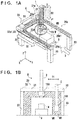
- FIG. 1A is a perspective view of a working device A including a working unit 100 according to an embodiment of the present invention.
- the arrows X and Y indicate two horizontal directions perpendicular to each other, and the arrow Z indicates a vertical direction.
- the working device A includes a plane movement mechanism 1 that moves the working unit 100 in a predetermined plane set in a working space WS described later, and a vertical movement mechanism 2 that moves the working unit 100 in a vertical plane perpendicular to the predetermined plane set in the working space WS.
- the plane movement mechanism 1 includes a plane guide portion 20 that guides the movement of the vertical movement mechanism 2.
- the plane guide portion 20 includes a first plane guide portion 20a that extends in the X direction, and a pair of second plane guide portions 20b that extend in the Y direction.
- the first plane guide portion 20a includes a first frame member 20a1 that is provided with a guide portion (not shown) for guiding the movement of the vertical movement mechanism 2 and extends in the X direction.
- the pair of second plane guide portions 20b include a pair of second frame members 20b1 that are each provided with a guide portion (not shown) for guiding the movement of the first frame member 20a1 and extend in the Y direction.
- the pair of second frame members 20b1 are arranged in parallel with each other and spaced apart from each other in the X direction.
- the plane movement mechanism 1 includes a first movement mechanism 21 that moves the vertical movement mechanism 2 in the X direction and a second movement mechanism 22 that moves the vertical movement mechanism 2 in the Y direction.
- the first movement mechanism 21 is provided with a first moving body 21a that moves following the guide by the first plane guide portion 20a, and a first drive mechanism (not shown) that moves the first moving body 21a.
- the vertical movement mechanism 2 is provided on the first moving body 21a and thereby moved in the X direction.
- the second movement mechanism 22 includes a pair of second moving bodies 22a1 that move following the guides by the pair of second plane guide portions 20b, and a second drive mechanism (not shown) that moves the second moving bodies 22a1.
- the first movement mechanism 21 is supported by the second moving bodies 22a1 and thereby moved in the Y direction, and the vertical movement mechanism 2 can be moved between the pair of second frame members 20b1 by the first movement mechanism 21 and the second movement mechanism 22.
- the vertical movement mechanism 2 is supported by the first moving body 21a in such a manner that the vertical movement mechanism 2 can be raised and lowered, and includes a vertical frame member vf that moves in the Z direction, and a vertical drive mechanism (not shown) that moves the vertical frame member vf in the Z direction.
- the working unit 100 described later is provided on a lower end of the vertical frame member vf.
- the first movement mechanism 21, the second movement mechanism 22, and the vertical movement mechanism 2 may be sliders based on the ball screw mechanism, for example, but are not limited thereto.
- the movement mechanisms may be rack and pinion mechanisms, nut and ball screw mechanisms, or belt transmission mechanisms that uses a motor or the like as a drive source.
- the working device A further includes strut portions 23 that support the plane guide portion 20 so that the working unit 100 can be moved in the working space.
- Four strut portions 23 are arranged to provide four corners under the pair of second movement mechanisms 22.
- the working device A has the working space WS defined by the four corner strut portions 23 below the plane guide portion 20.
- a placement unit 3 on which a workpiece W is placed and held, is arranged. The workpiece W is placed on the placement unit 3.
- FIG. 1B is a diagram for illustrating a working range in the working space WS of the working device A viewed in the direction of the arrow B in FIG. 1A .
- the region defined by the working range indicated by the chain line surrounding the placement unit 3 and the workpiece W is an effective working range WR.
- the shaded region outside the effective working range WR in FIG. 1B is a tool movement range MR.
- the effective working range WR is a range in which the working unit 100 can perform work on the workpiece W by being moved in the tool movement range MR by the first movement mechanism 21, the second movement mechanism 22, and the vertical movement mechanism 2.
- the working unit 100 can perform work on the workpiece placed on the placement unit 3 so long as the workpiece has such a size that the workpiece can be placed in the effective working range WR.
- the effective working range WR is described as a range surrounded by the chain line in this embodiment for the sake of explanation, the effective working range WR can be arbitrarily set within the range of the working space WS by moving the working unit 100 by controlling the operation of the first movement mechanism 21, the second movement mechanism 22, and the vertical movement mechanism 2 so that the workpiece W and the placement unit 3 do not interfere with the working unit 100.
- the working unit 100 is moved in the tool movement range MR by the plane guide portion 20 and the vertical movement mechanism 2, and is positioned with a tool T turned toward the workpiece W by a turning mechanism described later.
- the working unit 100 can access the workpiece W from all the directions except the direction of the placement unit 3 to perform work on the workpiece W.
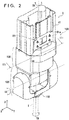
- FIG. 2 is a partial perspective view of the working unit 100.
- FIG. 2 shows the working unit 100 attached to the lower end of the vertical movement mechanism 2.
- the working unit 100 is attached to the lower end of the vertical frame member vf of the vertical movement mechanism 2 positioned above the working unit 100 in the drawing by an attachment portion 101.
- the working unit 100 is attached to the vertical movement mechanism 2 directly below the vertical movement mechanism 2 in the Z direction.
- a rotational axis TA of the tool T described later and the central position of the z axis of the vertical movement mechanism 2 in the X-Y plane can be aligned with each other.
- the working unit 100 includes a tool rotation mechanism 110 to which the tool T (indicated by the alternate long and two short dashes line) that performs work on the workpiece W disposed in the working space WS is rotatably attached, and a first turning mechanism 120 that turns the tool rotation mechanism 110 about a first axis 1A.
- the first axis 1A is an axis extending in a direction parallel with the X direction in FIG. 2 about which and the tool T is turned in the Y-Z plane by the first turning mechanism 120.
- the working unit 100 further includes a second turning mechanism 130 that turns the tool rotation mechanism 110 and the first turning mechanism 120 about a second axis 2A perpendicular to the first axis 1A.
- the second axis 2A is an axis extending in a direction parallel with the Z direction in FIG. 2 about which the first turning mechanism 120 and the tool T are turned in the X-Y plane by the second turning mechanism 130.
- the tool rotation mechanism 110 rotates the tool T about the rotational axis TA of the tool that extends in the Z direction in FIG. 2 .
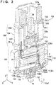
- FIG. 3 is a schematic cross-sectional view taken along the line indicated by the arrows III in FIG. 2 .
- FIGS. 4A and 4B are perspective views of the first turning mechanism 120 and the second turning mechanism 130. In FIG. 3 , illustration of exterior components of the vertical frame vf of the vertical mechanism 2 and the second turning mechanism 130 shown in FIG. 2 is omitted.
- FIGS. 4A and 4B show the working unit 100 in FIG. 2 with exterior components thereof removed.
- FIG. 4A is a perspective view of the working unit 100 viewed from one direction
- FIG. 4B is a perspective of the same viewed from another direction.
- the second turning mechanism 130 includes a rotating stage 131 that supports the first turning mechanism 120, a second rotational drive source 132 that rotates the rotating stage 131 about the second axis 2A, and a supporting body 133 that supports the second rotational drive source 132.
- the rotating stage 131 includes a rotatable connection portion 131a connected to a reducer 132a, and a connection portion 131b on which a stator 121 described later is fixedly supported.
- the rotating stage 131 further includes an arm supporting portion 131c connected to the rotatable connection portion 131a and thereby supported, to which the other arm portion 123b described later is rotatably connected.
- the second rotational drive source 132 is supported by the supporting body 133 and coupled to the rotating stage 131 via the reducer 132a (illustration of the detailed mechanism of which is omitted).
- the reducer 132a may be a reduction gear, for example. However, the reducer 132a is not limited thereto and may be a trochoid reduction gear or the like.
- the supporting body 133 includes a supporting portion 133a connected to the attachment portion 101 attached to the lower end of the vertical frame vf, and a motor housing portion 133b that is connected to the supporting portion 133a and houses the second rotational drive source 132.
- the motor housing portion 133b is a cylindrical member, in which a supporting portion (not shown) that supports the second rotational drive source 132 is provided.
- a housing supporting portion 1342 which is a portion of a housing portion 134 described later, is provided around the outer periphery of the supporting body 133.
- the supporting body 133 further includes a cover supporting portion 101a that supports a cover of the vertical frame vf of the vertical movement mechanism 2 on the supporting portion 133a.
- the second turning mechanism 130 includes the housing portion 134 that houses a cable C described later that is connected to the first turning mechanism 120 through the vertical frame vf, the supporting body 133, and the rotating stage 131.
- the housing portion 134 includes a cylindrical housing rotation portion 1341, which is a portion of the housing portion 134, that is connected to the rotating stage 131 so as to surround the outer periphery of the motor housing portion 133b and moves along with the rotating stage 131, and the housing supporting portion 1342, which is a portion of the housing portion 134, that is connected to the outer periphery of the motor housing portion 133b of the supporting body 133.
- the housing rotation portion 1341 and the housing supporting portion 1342 of the housing portion 134 are arranged to partially overlap with each other, and the housing rotation portion 1341 can rotate with respect to the housing supporting portion 1342.
- the first turning mechanism 120 includes the stator 121 connected to the second turning mechanism 130, and a rotor 122 provided inside the stator 121.
- the stator 121 is fixed to the rotating stage 131 of the second turning mechanism 130 and rotates integrally with the rotating stage 131.
- the stator 121 is a cylindrical member that is arranged with the longitudinal direction thereof aligned with the X direction in FIG. 3 .
- the rotor 122 is a hollow shaft-shaped member that is arranged inside the inner periphery of the stator 121 in such a manner that the rotor 122 can rotate about the first axis 1A as a central axis.
- the cable C described later can be inserted and arranged in the hollow rotor 122. Therefore, the stator 121 and the rotor 122 form a hollow motor with the rotor 122 rotating with respect to the stator 121.
- a second rotating body 123 that holds the tool rotation mechanism 110 is fixed to the rotor 122.
- the second rotating body 123 includes one arm portion 123a that is coupled to one end portion (the right end portion in the X direction in the drawing) of the rotor 122.
- the one arm portion 123a includes a connection arm portion 1231 that is connected to the one end portion of the rotor 122 on one side thereof, and a tool supporting arm portion 123a2 that is arranged in parallel with the first axis 1A and is provided with the tool rotation mechanism 110 described later on the other side thereof.
- the second rotating body 123 includes the other arm portion 123b that is provided on the side of the other end portion of the rotor 122 (on the left side in the X direction in the drawing) and is rotatably coupled to the arm supporting portion 131c, and an arm coupling portion 123c that couples the one arm portion 123a and the other arm portion 123b to each other.
- the second rotating body 123 is not limited to the implementation described above, and the other arm portion 123b may be coupled to the rotor 122, for example.
- the cable C for supplying electric power or the like to the tool rotation mechanism 110 can be arranged in the rotor 122.
- the cable C from a rotational drive source 113a of the tool rotation mechanism 110 described later may be routed from the side of the one arm portion 123a to the side of the other arm portion 123b through the rotor 122 and then routed upward into a housing space 134a of the housing portion 134.
- a round cable may be used as the cable C, for example.
- the cable C extending from the first turning mechanism 120 is routed into a main section 134a through a portion (a rotational communication portion formed in the rotating stage 131) denoted by C1 in the drawing.
- the cable C is then routed in the housing space 134a in two vertical layers and then to the vertical frame vf of the vertical movement mechanism 2 (not shown in the drawing) through a portion (a supporting communication portion formed in the supporting body 133) denoted by C2 in the drawing.
- the cable C can be routed in a smaller space and can be routed without a break even if the rotating stage 131 rotates 360 degrees or more with respect to the supporting body 133.
- the one arm portion 123a includes a communication portion 123a1 formed in the connection arm portion 1231 in which the cable (wire) C can be connected to the tool rotation mechanism 110 through the hollow portion of the rotor 122. Therefore, routing of the cable C can be improved, the size and weight of the working unit 100 can be reduced, and the dead space can be reduced.
- the tool rotation mechanism 110 includes a main body portion 111 that is supported by the second rotating body 123 connected to the rotor 122, a rotating body 112 that is attached to the main body portion 111 and rotates the tool T, and a drive transmission portion 113 that transmits a rotational drive force to the rotating body 112.
- the main body portion 111 is fixed to a lower surface of the tool supporting arm portion 123a2 of the second rotating body 123.
- the rotating body 112 is held on the main body portion 111 in such a manner that the rotating body 112 can rotate with respect to the main body portion 111, and can turn about the rotational axis TA of the tool.
- the rotating body 112 is rotated by the rotational drive force supplied from the rotational drive source 113a described later of the drive transmission portion 113, thereby rotating the tool attached thereto.
- the rotating body 112 has a tool attachment portion for the tool T (not shown).
- the drive transmission portion 113 includes the rotational drive source 113a that supplies a rotational drive force, and a transmission mechanism 113b that transmits the rotational drive force from the rotational drive source 113a to the rotating body 112.
- the rotational drive source 113a is disposed on a drive supporting portion 123d provided adjacent to (offset from) the one arm portion 123a of the second rotating body 123 in the direction of extension of the first axis 1A.
- the rotational drive source 113a is provided in such a manner that a drive rotational axis 113a1 thereof is in parallel with the rotational axis TA of the tool and is offset from the rotational axis TA of the tool in the direction of extension of the first axis 1A (in the radial direction from the rotational axis of the tool).
- the tool rotation mechanism 110 and the rotational drive source 113a that rotates the tool rotation mechanism 110 are not directly coupled to each other in the vertical direction (Z axis direction) but are coupled to each other by the transmission mechanism 113b.
- the rotational drive source 113a is not coupled to a lower side in the vertical direction (Z axis direction) of the first turning mechanism 120 in the state shown in FIG. 3 but is coupled to the rotating body 112 of the first turning mechanism 120.
- the second axis 2A of the second turning mechanism 130 and the drive rotational axis 113a1 of the rotational drive source 113a are not aligned with each other, and the drive rotational axis 113a1 is arranged offset from the second axis 2A in the direction of extension of the first axis 1A.
- the tool rotation mechanism 110 is coupled to the offset-arranged drive rotational axis 113al by the transmission mechanism 113b.
- the rotational axis TA of the tool in the tool rotation mechanism 110 is aligned with the second axis 2A.
- the distance from the lower end of the vertical frame member vf of the vertical movement mechanism 2 to the tool attachment portion of the rotating body 112 can be reduced. Therefore, working in the working range in the predetermined working area can be performed efficiently.
- the transmission mechanism 113b may be a belt transmission mechanism in this embodiment.
- the belt transmission mechanism may include a driving pulley 113b1 fixed to the drive rotational axis 113al of the rotational drive source 113a, a driven pulley 113b2 fixed to the rotating body 112, and a driving belt 113b3 wound around the driving pulley 113b1 and the driven pulley 113b2. Therefore, the rotational drive force from the rotational drive source 113a is transmitted to the tool via the drive rotational axis 113al, the driving pulley 113b1, the driving belt 113b3, the driven pulley 113b2, and the rotating body 112.
- the transmission mechanism 113b is not limited to the belt transmission mechanism, but may include a plurality of gears coupled to transmit a drive force or a drive shaft used to transmit a drive force, for example.
- the extension line of the rotational axis TA of the tool passes through an intersection of the first axis 1A of the first turning mechanism 120 and the second axis 2A of the second turning mechanism 130. That is, when the tool is turned about the first axis 1A by the first turning mechanism 120, the distance between the first axis 1A and the tool does not change. Furthermore, when the first turning mechanism 120 is turned by the second turning mechanism 130, the distance between the second axis 2A and the tool does not change. Therefore, the position of the tool can be accurately grasped.
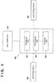
- FIG. 6 is a block diagram showing a control unit 500 that controls the working device A according to this embodiment.
- the control unit 500 includes a processing unit 510, a storage unit 520, and an interface unit 530, which are connected to each other by a bus (not shown).
- the processing unit 510 executes a program stored in the storage unit 520.
- the processing unit 510 is a CPU, for example.
- the storage unit 520 is a RAM, a ROM, or a hard disk or the like, for example.
- the interface unit 530 is provided between the processing unit 510 and an external device (a host computer 540, input equipment (a sensor, for example) 550 and output equipment (an actuator for each drive mechanism, for example) 560), and is a communication interface or an I/O interface or the like, for example.
- an external device a host computer 540, input equipment (a sensor, for example) 550 and output equipment (an actuator for each drive mechanism, for example) 560, and is a communication interface or an I/O interface or the like, for example.
- the working unit 100 and the working device A since the axial center 2A along the Z axis of the vertical movement mechanism 2 and the axial center TA along the Z axis of the working unit 100 are aligned with each other, the moment rigidity of the vertical movement mechanism 2 and the working unit 100 is improved, and the working unit 100 can carry a greater weight.
- the hollow shaft-shaped rotor is adopted, routing of the cable is improved, and the weight and size of the working unit 100 can be reduced.
- the rotational axis TA of the tool of the tool rotation mechanism 110 is aligned with the axial center 2A along the Z axis of the vertical movement mechanism 2
- the drive rotational axis 113al of the rotational drive source 113a of the tool rotation mechanism 110 is not aligned with but is offset from the axial center 2A along the Z axis of the vertical movement mechanism 2.
- the tool rotation mechanism 110 is coupled to the rotational drive source 113a by the transmission mechanism 113b.
- the distance between the lower end of the vertical frame member vf of the vertical movement mechanism 2 and the tool attachment portion of the rotating body 112 can be reduced, so that the working range in the working area can be efficiently used.
- the cable C is routed in the housing portion 134, the cable C can be prevented from being broken by the first turning mechanism 120 when the first turning mechanism 120 is turned by the second turning mechanism 130.
Description
- The present invention relates to a working unit and a working device.
- There is a working robot that moves a working tool for performing predetermined work (such as machining, assembly, or measurement) on a workpiece, which is a working target, placed at a placement position in a working area, and positions the tool at an optimal angle for the work.
- In
PTL 1, there is described a working robot that includes a tip end unit including a tool rotation mechanism that rotates a working tool in a horizontal direction, a tool movement mechanism that moves the tool at a predetermined angle in a vertical direction, an orthogonal movement mechanism that moves the tip end unit to a working position for a work piece disposed at a predetermined position in a working area, and a workpiece turning mechanism that holds the workpiece and turns the workpiece in the horizontal direction. - In PTL 2, there is described a working robot that includes a tip end unit including a tool rotation mechanism that rotates a working tool in a horizontal direction, a tool movement mechanism that moves the tool at a predetermined angle in a vertical direction, a lifting and lowering movement mechanism that vertically moves the tip end unit to a working position for a work piece disposed at a predetermined position in a working area, and a plane movement mechanism that moves the work piece disposed at the predetermined position in a plane at a predetermined height in the working area.
- In
PTL 3, there is described a working robot that is a vertical articulated robot provided with a working tool for deburring a workpiece. -
- PTL1 : Japanese Patent
JPS59175964U - PTL2: Japanese Patent
JPS59175965U - PTL3: Japanese Patent
JP3095032B -
EP 2 080 581 A1 discloses a machining head for a machine tool which includes a spindle unit having a spindle to which a tool is attachable and a support head component. - The device described in
PTL 1 cannot perform work on a workpiece that is still at a predetermined position from directions other than the horizontal direction, since the tip end unit can only turn the working tool about a horizontal axis that is parallel to the horizontal direction and rotate the tool in the horizontal direction. - To cope with the problem, the device described in PTL 2 includes the horizontal rotation mechanism that rotationally drives a rotating table capable of rotating in the horizontal direction on which the workpiece is placed, so that the workpiece can be rotated and moved to the working position so that various surfaces of the workpiece can be processed. However, a large movement mechanism is needed to move a heavy or large workpiece, and the device is inevitably large-scale.
- The device described in
PTL 3 is a vertical articulated robot having a working tool attached to the tip end thereof for work. However, when the robot performs work on a workpiece at a high level from the base of the robot, arms of the robot can interfere with each other, so that the vertical articulated robot needs to be larger than necessary. - In view of such circumstances, an object of the present invention is to provide a working unit and a working device that efficiently perform work on a workpiece disposed in a preset working area from many directions.
- The present invention in a first aspect provides a working unit as specified in
claims 1 to 4. - The present invention in a second aspect provides a working device as specified in claims 5 to 7.
- According to the present invention, work can be efficiently performed on a workpiece disposed in a preset working area from many directions.
-
-
FIG. 1A is a diagram for illustrating a working device according to an embodiment of the present invention. -
FIG. 1B is a diagram for illustrating a working range of the working device shown inFIG. 1A . -
FIG. 2 is a partial perspective view of a working unit. -
FIG. 3 is a cross-sectional view of the working unit shown inFIG. 2 . -
FIG. 4A is a perspective view for illustrating the working unit shown inFIG. 2 . -
FIG. 4B is a perspective view for illustrating the working unit shown inFIG. 2 . -
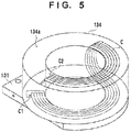
FIG. 5 is a perspective view showing a housing portion for a wire. -
FIG. 6 is a block diagram showing a control unit. - In the following, an illustrative embodiment of the present invention will be described with reference to the drawings. In the drawings, the same reference numerals denote the same elements, and in the description herein, the vertical and horizontal directions in the drawings will be used to indicate the vertical and horizontal directions of devices or members thereof according to the embodiment.
-
FIG. 1A is a perspective view of a working device A including a workingunit 100 according to an embodiment of the present invention. InFIG. 1A , the arrows X and Y indicate two horizontal directions perpendicular to each other, and the arrow Z indicates a vertical direction. The working device A includes aplane movement mechanism 1 that moves the workingunit 100 in a predetermined plane set in a working space WS described later, and a vertical movement mechanism 2 that moves the workingunit 100 in a vertical plane perpendicular to the predetermined plane set in the working space WS. Theplane movement mechanism 1 includes aplane guide portion 20 that guides the movement of the vertical movement mechanism 2. - The
plane guide portion 20 includes a first plane guide portion 20a that extends in the X direction, and a pair of secondplane guide portions 20b that extend in the Y direction. The first plane guide portion 20a includes a first frame member 20a1 that is provided with a guide portion (not shown) for guiding the movement of the vertical movement mechanism 2 and extends in the X direction. The pair of secondplane guide portions 20b include a pair of second frame members 20b1 that are each provided with a guide portion (not shown) for guiding the movement of the first frame member 20a1 and extend in the Y direction. The pair of second frame members 20b1 are arranged in parallel with each other and spaced apart from each other in the X direction. - The
plane movement mechanism 1 includes afirst movement mechanism 21 that moves the vertical movement mechanism 2 in the X direction and asecond movement mechanism 22 that moves the vertical movement mechanism 2 in the Y direction. Thefirst movement mechanism 21 is provided with a first movingbody 21a that moves following the guide by the first plane guide portion 20a, and a first drive mechanism (not shown) that moves the first movingbody 21a. The vertical movement mechanism 2 is provided on the first movingbody 21a and thereby moved in the X direction. Thesecond movement mechanism 22 includes a pair of second moving bodies 22a1 that move following the guides by the pair of secondplane guide portions 20b, and a second drive mechanism (not shown) that moves the second moving bodies 22a1. Thefirst movement mechanism 21 is supported by the second moving bodies 22a1 and thereby moved in the Y direction, and the vertical movement mechanism 2 can be moved between the pair of second frame members 20b1 by thefirst movement mechanism 21 and thesecond movement mechanism 22. - The vertical movement mechanism 2 is supported by the first moving
body 21a in such a manner that the vertical movement mechanism 2 can be raised and lowered, and includes a vertical frame member vf that moves in the Z direction, and a vertical drive mechanism (not shown) that moves the vertical frame member vf in the Z direction. The workingunit 100 described later is provided on a lower end of the vertical frame member vf. - The
first movement mechanism 21, thesecond movement mechanism 22, and the vertical movement mechanism 2 may be sliders based on the ball screw mechanism, for example, but are not limited thereto. For example, the movement mechanisms may be rack and pinion mechanisms, nut and ball screw mechanisms, or belt transmission mechanisms that uses a motor or the like as a drive source. - The working device A further includes
strut portions 23 that support theplane guide portion 20 so that the workingunit 100 can be moved in the working space. Fourstrut portions 23 are arranged to provide four corners under the pair ofsecond movement mechanisms 22. The working device A has the working space WS defined by the fourcorner strut portions 23 below theplane guide portion 20. In the working space WS, aplacement unit 3, on which a workpiece W is placed and held, is arranged. The workpiece W is placed on theplacement unit 3. -
FIG. 1B is a diagram for illustrating a working range in the working space WS of the working device A viewed in the direction of the arrow B inFIG. 1A . InFIG. 1B , the region defined by the working range indicated by the chain line surrounding theplacement unit 3 and the workpiece W is an effective working range WR. The shaded region outside the effective working range WR inFIG. 1B is a tool movement range MR. The effective working range WR is a range in which the workingunit 100 can perform work on the workpiece W by being moved in the tool movement range MR by thefirst movement mechanism 21, thesecond movement mechanism 22, and the vertical movement mechanism 2. Therefore, the workingunit 100 can perform work on the workpiece placed on theplacement unit 3 so long as the workpiece has such a size that the workpiece can be placed in the effective working range WR. Although the effective working range WR is described as a range surrounded by the chain line in this embodiment for the sake of explanation, the effective working range WR can be arbitrarily set within the range of the working space WS by moving the workingunit 100 by controlling the operation of thefirst movement mechanism 21, thesecond movement mechanism 22, and the vertical movement mechanism 2 so that the workpiece W and theplacement unit 3 do not interfere with the workingunit 100. - The working
unit 100 is moved in the tool movement range MR by theplane guide portion 20 and the vertical movement mechanism 2, and is positioned with a tool T turned toward the workpiece W by a turning mechanism described later. Thus, in the working space WS, the workingunit 100 can access the workpiece W from all the directions except the direction of theplacement unit 3 to perform work on the workpiece W. -
FIG. 2 is a partial perspective view of the workingunit 100.FIG. 2 shows the workingunit 100 attached to the lower end of the vertical movement mechanism 2. The workingunit 100 is attached to the lower end of the vertical frame member vf of the vertical movement mechanism 2 positioned above the workingunit 100 in the drawing by anattachment portion 101. The workingunit 100 is attached to the vertical movement mechanism 2 directly below the vertical movement mechanism 2 in the Z direction. As a result, a rotational axis TA of the tool T described later and the central position of the z axis of the vertical movement mechanism 2 in the X-Y plane can be aligned with each other. - The working
unit 100 includes atool rotation mechanism 110 to which the tool T (indicated by the alternate long and two short dashes line) that performs work on the workpiece W disposed in the working space WS is rotatably attached, and afirst turning mechanism 120 that turns thetool rotation mechanism 110 about afirst axis 1A. Thefirst axis 1A is an axis extending in a direction parallel with the X direction inFIG. 2 about which and the tool T is turned in the Y-Z plane by thefirst turning mechanism 120. - The working
unit 100 further includes asecond turning mechanism 130 that turns thetool rotation mechanism 110 and thefirst turning mechanism 120 about asecond axis 2A perpendicular to thefirst axis 1A. Thesecond axis 2A is an axis extending in a direction parallel with the Z direction inFIG. 2 about which thefirst turning mechanism 120 and the tool T are turned in the X-Y plane by thesecond turning mechanism 130. Thetool rotation mechanism 110 rotates the tool T about the rotational axis TA of the tool that extends in the Z direction inFIG. 2 . -
FIG. 3 is a schematic cross-sectional view taken along the line indicated by the arrows III inFIG. 2 .FIGS. 4A and 4B are perspective views of thefirst turning mechanism 120 and thesecond turning mechanism 130. InFIG. 3 , illustration of exterior components of the vertical frame vf of the vertical mechanism 2 and thesecond turning mechanism 130 shown inFIG. 2 is omitted.FIGS. 4A and 4B show the workingunit 100 inFIG. 2 with exterior components thereof removed.FIG. 4A is a perspective view of the workingunit 100 viewed from one direction, andFIG. 4B is a perspective of the same viewed from another direction. - The
second turning mechanism 130 includes arotating stage 131 that supports thefirst turning mechanism 120, a secondrotational drive source 132 that rotates therotating stage 131 about thesecond axis 2A, and a supportingbody 133 that supports the secondrotational drive source 132. - As shown in
FIGS. 3 ,4A, and 4B , therotating stage 131 includes arotatable connection portion 131a connected to areducer 132a, and aconnection portion 131b on which astator 121 described later is fixedly supported. Therotating stage 131 further includes anarm supporting portion 131c connected to therotatable connection portion 131a and thereby supported, to which theother arm portion 123b described later is rotatably connected. The secondrotational drive source 132 is supported by the supportingbody 133 and coupled to therotating stage 131 via thereducer 132a (illustration of the detailed mechanism of which is omitted). Thereducer 132a may be a reduction gear, for example. However, thereducer 132a is not limited thereto and may be a trochoid reduction gear or the like. - The supporting
body 133 includes a supportingportion 133a connected to theattachment portion 101 attached to the lower end of the vertical frame vf, and amotor housing portion 133b that is connected to the supportingportion 133a and houses the secondrotational drive source 132. In this embodiment, themotor housing portion 133b is a cylindrical member, in which a supporting portion (not shown) that supports the secondrotational drive source 132 is provided. Ahousing supporting portion 1342, which is a portion of ahousing portion 134 described later, is provided around the outer periphery of the supportingbody 133. The supportingbody 133 further includes acover supporting portion 101a that supports a cover of the vertical frame vf of the vertical movement mechanism 2 on the supportingportion 133a. - The
second turning mechanism 130 includes thehousing portion 134 that houses a cable C described later that is connected to thefirst turning mechanism 120 through the vertical frame vf, the supportingbody 133, and therotating stage 131. Thehousing portion 134 includes a cylindricalhousing rotation portion 1341, which is a portion of thehousing portion 134, that is connected to therotating stage 131 so as to surround the outer periphery of themotor housing portion 133b and moves along with therotating stage 131, and thehousing supporting portion 1342, which is a portion of thehousing portion 134, that is connected to the outer periphery of themotor housing portion 133b of the supportingbody 133. Thehousing rotation portion 1341 and thehousing supporting portion 1342 of thehousing portion 134 are arranged to partially overlap with each other, and thehousing rotation portion 1341 can rotate with respect to thehousing supporting portion 1342. - The
first turning mechanism 120 includes thestator 121 connected to thesecond turning mechanism 130, and arotor 122 provided inside thestator 121. Thestator 121 is fixed to therotating stage 131 of thesecond turning mechanism 130 and rotates integrally with therotating stage 131. Thestator 121 is a cylindrical member that is arranged with the longitudinal direction thereof aligned with the X direction inFIG. 3 . - The
rotor 122 is a hollow shaft-shaped member that is arranged inside the inner periphery of thestator 121 in such a manner that therotor 122 can rotate about thefirst axis 1A as a central axis. The cable C described later can be inserted and arranged in thehollow rotor 122. Therefore, thestator 121 and therotor 122 form a hollow motor with therotor 122 rotating with respect to thestator 121. - A second
rotating body 123 that holds thetool rotation mechanism 110 is fixed to therotor 122. The secondrotating body 123 includes onearm portion 123a that is coupled to one end portion (the right end portion in the X direction in the drawing) of therotor 122. The onearm portion 123a includes aconnection arm portion 1231 that is connected to the one end portion of therotor 122 on one side thereof, and a tool supporting arm portion 123a2 that is arranged in parallel with thefirst axis 1A and is provided with thetool rotation mechanism 110 described later on the other side thereof. The secondrotating body 123 includes theother arm portion 123b that is provided on the side of the other end portion of the rotor 122 (on the left side in the X direction in the drawing) and is rotatably coupled to thearm supporting portion 131c, and anarm coupling portion 123c that couples the onearm portion 123a and theother arm portion 123b to each other. The secondrotating body 123 is not limited to the implementation described above, and theother arm portion 123b may be coupled to therotor 122, for example. - Since the motor including the hollow shaft-shaped
rotor 122 is adopted as described above, the cable C for supplying electric power or the like to thetool rotation mechanism 110 can be arranged in therotor 122. For example, as shown inFIG. 3 , the cable C from arotational drive source 113a of thetool rotation mechanism 110 described later may be routed from the side of the onearm portion 123a to the side of theother arm portion 123b through therotor 122 and then routed upward into ahousing space 134a of thehousing portion 134. - Furthermore, as shown in
FIG. 5 , a round cable may be used as the cable C, for example. The cable C extending from thefirst turning mechanism 120 is routed into amain section 134a through a portion (a rotational communication portion formed in the rotating stage 131) denoted by C1 in the drawing. The cable C is then routed in thehousing space 134a in two vertical layers and then to the vertical frame vf of the vertical movement mechanism 2 (not shown in the drawing) through a portion (a supporting communication portion formed in the supporting body 133) denoted by C2 in the drawing. By adopting the round cable, the cable C can be routed in a smaller space and can be routed without a break even if therotating stage 131 rotates 360 degrees or more with respect to the supportingbody 133. - Therefore, according to this embodiment, the one
arm portion 123a includes a communication portion 123a1 formed in theconnection arm portion 1231 in which the cable (wire) C can be connected to thetool rotation mechanism 110 through the hollow portion of therotor 122. Therefore, routing of the cable C can be improved, the size and weight of the workingunit 100 can be reduced, and the dead space can be reduced. - Referring again to
FIGS. 3 ,4A and 4B , thetool rotation mechanism 110 includes a main body portion 111 that is supported by the secondrotating body 123 connected to therotor 122, arotating body 112 that is attached to the main body portion 111 and rotates the tool T, and adrive transmission portion 113 that transmits a rotational drive force to therotating body 112. The main body portion 111 is fixed to a lower surface of the tool supporting arm portion 123a2 of the secondrotating body 123. Therotating body 112 is held on the main body portion 111 in such a manner that therotating body 112 can rotate with respect to the main body portion 111, and can turn about the rotational axis TA of the tool. Therotating body 112 is rotated by the rotational drive force supplied from therotational drive source 113a described later of thedrive transmission portion 113, thereby rotating the tool attached thereto. Therotating body 112 has a tool attachment portion for the tool T (not shown). - The
drive transmission portion 113 includes therotational drive source 113a that supplies a rotational drive force, and atransmission mechanism 113b that transmits the rotational drive force from therotational drive source 113a to therotating body 112. In this embodiment, therotational drive source 113a is disposed on adrive supporting portion 123d provided adjacent to (offset from) the onearm portion 123a of the secondrotating body 123 in the direction of extension of thefirst axis 1A. Therotational drive source 113a is provided in such a manner that a drive rotational axis 113a1 thereof is in parallel with the rotational axis TA of the tool and is offset from the rotational axis TA of the tool in the direction of extension of thefirst axis 1A (in the radial direction from the rotational axis of the tool). - In this embodiment, the
tool rotation mechanism 110 and therotational drive source 113a that rotates thetool rotation mechanism 110 are not directly coupled to each other in the vertical direction (Z axis direction) but are coupled to each other by thetransmission mechanism 113b. Specifically, therotational drive source 113a is not coupled to a lower side in the vertical direction (Z axis direction) of thefirst turning mechanism 120 in the state shown inFIG. 3 but is coupled to therotating body 112 of thefirst turning mechanism 120. In other words, thesecond axis 2A of thesecond turning mechanism 130 and the drive rotational axis 113a1 of therotational drive source 113a are not aligned with each other, and the drive rotational axis 113a1 is arranged offset from thesecond axis 2A in the direction of extension of thefirst axis 1A. Thetool rotation mechanism 110 is coupled to the offset-arranged drive rotational axis 113al by thetransmission mechanism 113b. The rotational axis TA of the tool in thetool rotation mechanism 110 is aligned with thesecond axis 2A. Thus, as compared with a case where thesecond axis 2A, the drive rotational axis 113a1, and the rotational axis TA of the tool are aligned with each other, the distance from the lower end of the vertical frame member vf of the vertical movement mechanism 2 to the tool attachment portion of therotating body 112 can be reduced. Therefore, working in the working range in the predetermined working area can be performed efficiently. - The
transmission mechanism 113b may be a belt transmission mechanism in this embodiment. The belt transmission mechanism may include a driving pulley 113b1 fixed to the drive rotational axis 113al of therotational drive source 113a, a driven pulley 113b2 fixed to therotating body 112, and a driving belt 113b3 wound around the driving pulley 113b1 and the driven pulley 113b2. Therefore, the rotational drive force from therotational drive source 113a is transmitted to the tool via the drive rotational axis 113al, the driving pulley 113b1, the driving belt 113b3, the driven pulley 113b2, and therotating body 112. Thetransmission mechanism 113b is not limited to the belt transmission mechanism, but may include a plurality of gears coupled to transmit a drive force or a drive shaft used to transmit a drive force, for example. - The extension line of the rotational axis TA of the tool passes through an intersection of the
first axis 1A of thefirst turning mechanism 120 and thesecond axis 2A of thesecond turning mechanism 130. That is, when the tool is turned about thefirst axis 1A by thefirst turning mechanism 120, the distance between thefirst axis 1A and the tool does not change. Furthermore, when thefirst turning mechanism 120 is turned by thesecond turning mechanism 130, the distance between thesecond axis 2A and the tool does not change. Therefore, the position of the tool can be accurately grasped. -
FIG. 6 is a block diagram showing acontrol unit 500 that controls the working device A according to this embodiment. Thecontrol unit 500 includes aprocessing unit 510, astorage unit 520, and aninterface unit 530, which are connected to each other by a bus (not shown). Theprocessing unit 510 executes a program stored in thestorage unit 520. Theprocessing unit 510 is a CPU, for example. Thestorage unit 520 is a RAM, a ROM, or a hard disk or the like, for example. Theinterface unit 530 is provided between theprocessing unit 510 and an external device (ahost computer 540, input equipment (a sensor, for example) 550 and output equipment (an actuator for each drive mechanism, for example) 560), and is a communication interface or an I/O interface or the like, for example. - With the working
unit 100 and the working device A according to this embodiment described above, since theaxial center 2A along the Z axis of the vertical movement mechanism 2 and the axial center TA along the Z axis of the workingunit 100 are aligned with each other, the moment rigidity of the vertical movement mechanism 2 and the workingunit 100 is improved, and the workingunit 100 can carry a greater weight. In addition, since the hollow shaft-shaped rotor is adopted, routing of the cable is improved, and the weight and size of the workingunit 100 can be reduced. In addition, although the rotational axis TA of the tool of thetool rotation mechanism 110 is aligned with theaxial center 2A along the Z axis of the vertical movement mechanism 2, the drive rotational axis 113al of therotational drive source 113a of thetool rotation mechanism 110 is not aligned with but is offset from theaxial center 2A along the Z axis of the vertical movement mechanism 2. In addition, thetool rotation mechanism 110 is coupled to therotational drive source 113a by thetransmission mechanism 113b. As a result, the distance between the lower end of the vertical frame member vf of the vertical movement mechanism 2 and the tool attachment portion of therotating body 112 can be reduced, so that the working range in the working area can be efficiently used. Furthermore, since the cable C is routed in thehousing portion 134, the cable C can be prevented from being broken by thefirst turning mechanism 120 when thefirst turning mechanism 120 is turned by thesecond turning mechanism 130. - The present invention is not limited to the above embodiment, and various changes and modifications can be made within the scope of the claims. Therefore, to apprise the public of the scope of the present invention, the following claims are made.
Claims (7)
- A working unit (100) to which a tool (T) for performing work on a workpiece (W) disposed in a working space (WS) is attached, the working unit (100) comprising:a tool rotation mechanism (110) that rotates the tool (T);a first turning mechanism (120) that turns the tool rotation mechanism (110) about a first axis (1A); anda second turning mechanism (130) that turns the tool rotation mechanism (110) and the first turning mechanism (120) about a second axis (2A) perpendicular to the first axis (1A),characterized in that the second turning mechanism (130) includes a rotating stage (131) that supports the first turning mechanism (120),the rotating stage (131) includes an arm supporting portion (131c),the first turning mechanism (120) includes:a motor (121,122) that has a stator (121) connected to the second turning mechanism (130) and a rotor (122) that is a hollow shaft-shaped rotor and is arranged inside an inner periphery of the stator (121) in such a manner that the rotor (122) is capable of rotating about the first axis (1A) as a central axis; anda second rotating body (123) that includes one arm portion (123a) coupled to one end portion of the rotor, the other arm portion (123b) that is provided on the side of the other end portion of the rotor (122), and is rotatably coupled to the arm supporting portion (131c), and an arm coupling portion (123c) that couples the one arm portion (123a) and the other arm portion (123b) to each other, andthe tool rotation mechanism (110) is provided on the second rotating body (123).
- The working unit according to claim 1, wherein the one arm portion (123a) has a communication portion (123a1) through which a wire (C) connected to the tool rotation mechanism (110) is capable of being routed through a hollow portion of the rotor (122).
- The working unit according to claim 1, wherein the second turning mechanism (130) includes:a second rotational drive source (132) that rotates the rotating stage (131) about the second axis(2A); anda supporting body (133) that supports the second rotational drive source (132).
- The working unit according to claim 3, wherein the second turning mechanism (130) includes a housing portion (134) that houses the wire (C) routed from the supporting body (133) to the rotating stage (131) around an outer periphery side of the second rotational drive source (132).
- A working device (A), comprising:the working unit (100) according to claim 1;a plane movement mechanism (1) that moves the working unit (100) in a predetermined plane set in the working space (WS); anda vertical movement mechanism (2) that moves the working unit in a vertical plane perpendicular to the predetermined plane set in the working space (WS).
- The working device according to claim 5, further comprising:
a placement unit (3) arranged in the working space (WS) on which the workpiece (W) is placed and held. - The working device according to claim 6, wherein the plane movement mechanism (3) includes a plane guide portion (20) that guides a movement of the vertical movement mechanism (2), and
the working device (A) further comprises a strut portion (23) that supports the plane guide portion (20) in such a manner that the working unit (100) is capable of being moved in the working space (WS).
Applications Claiming Priority (3)
| Application Number | Priority Date | Filing Date | Title |
|---|---|---|---|
| JP2016051348A JP6498140B2 (en) | 2016-03-15 | 2016-03-15 | Work unit and work device |
| EP17766428.1A EP3409430B1 (en) | 2016-03-15 | 2017-03-06 | Working unit and working device |
| PCT/JP2017/008753 WO2017159426A1 (en) | 2016-03-15 | 2017-03-06 | Work unit and work device |
Related Parent Applications (2)
| Application Number | Title | Priority Date | Filing Date |
|---|---|---|---|
| EP17766428.1A Division-Into EP3409430B1 (en) | 2016-03-15 | 2017-03-06 | Working unit and working device |
| EP17766428.1A Division EP3409430B1 (en) | 2016-03-15 | 2017-03-06 | Working unit and working device |
Publications (2)
| Publication Number | Publication Date |
|---|---|
| EP3610995A1 EP3610995A1 (en) | 2020-02-19 |
| EP3610995B1 true EP3610995B1 (en) | 2021-02-24 |
Family
ID=59850690
Family Applications (2)
| Application Number | Title | Priority Date | Filing Date |
|---|---|---|---|
| EP17766428.1A Active EP3409430B1 (en) | 2016-03-15 | 2017-03-06 | Working unit and working device |
| EP19200997.5A Active EP3610995B1 (en) | 2016-03-15 | 2017-03-06 | Working unit and working device |
Family Applications Before (1)
| Application Number | Title | Priority Date | Filing Date |
|---|---|---|---|
| EP17766428.1A Active EP3409430B1 (en) | 2016-03-15 | 2017-03-06 | Working unit and working device |
Country Status (5)
| Country | Link |
|---|---|
| US (1) | US11173596B2 (en) |
| EP (2) | EP3409430B1 (en) |
| JP (1) | JP6498140B2 (en) |
| CN (1) | CN108883537B (en) |
| WO (1) | WO2017159426A1 (en) |
Families Citing this family (3)
| Publication number | Priority date | Publication date | Assignee | Title |
|---|---|---|---|---|
| JP2017131969A (en) * | 2016-01-25 | 2017-08-03 | セイコーエプソン株式会社 | robot |
| CN111941399A (en) * | 2020-08-19 | 2020-11-17 | 连城凯克斯科技有限公司 | double-Z-axis mechanism |
| CN114161172A (en) * | 2021-11-26 | 2022-03-11 | 广东欧亚特机械设备有限公司 | Five-axis spindle head and machining center |
Family Cites Families (34)
| Publication number | Priority date | Publication date | Assignee | Title |
|---|---|---|---|---|
| JPS59175965A (en) | 1983-03-18 | 1984-10-05 | 松下電器産業株式会社 | Robot device |
| JPS59175964A (en) | 1983-03-18 | 1984-10-05 | 松下電器産業株式会社 | Robot device |
| JPS59175964U (en) | 1983-05-11 | 1984-11-24 | ダイキン工業株式会社 | Air conditioning equipment |
| JPS59175965U (en) | 1983-05-12 | 1984-11-24 | 松下電器産業株式会社 | Integrated heating and cooling air conditioner |
| US5155423A (en) * | 1986-02-18 | 1992-10-13 | Robotics Research Corporation | Industrial robot with servo |
| JPS62287991A (en) * | 1986-06-09 | 1987-12-14 | ファナック株式会社 | Wrist drive mechanism of industrial robot |
| JPH01234191A (en) | 1988-03-10 | 1989-09-19 | Internatl Business Mach Corp <Ibm> | Manipulator-assembly |
| IT1245433B (en) | 1991-03-04 | 1994-09-20 | Comau Spa | INDUSTRIAL ROBOT WRIST |
| JP3095032B2 (en) | 1991-10-09 | 2000-10-03 | ヤマハ発動機株式会社 | Robot hand for work |
| JPH07124887A (en) * | 1993-10-29 | 1995-05-16 | Fanuc Ltd | Cable treating device for industrial robot |
| JP3069941B2 (en) * | 1994-05-30 | 2000-07-24 | 本田技研工業株式会社 | Power supply device at the wrist of the robot |
| JPH0819985A (en) * | 1994-07-04 | 1996-01-23 | Mitsubishi Electric Corp | Robot device |
| JP2626623B2 (en) * | 1995-04-12 | 1997-07-02 | 日本電気株式会社 | Rotation mechanism |
| US5584621A (en) * | 1995-06-13 | 1996-12-17 | Bertsche Engineering Corp. | Direct drive multiple axes rotary spindle head for milling machine |
| JPH09141593A (en) * | 1995-11-17 | 1997-06-03 | Yaskawa Electric Corp | Industrial robot |
| JPH11207684A (en) * | 1998-01-21 | 1999-08-03 | Kokusai Electric Co Ltd | Two spindle rotation drive device |
| DE20204365U1 (en) * | 2002-03-19 | 2002-05-29 | Deckel Maho Pfronten Gmbh | Spindle head for a universal milling machine |
| DE102005006221A1 (en) * | 2005-02-10 | 2006-08-17 | Benz Gmbh Werkzeug- U. Maschinenbau Kg | Driven tool holder |
| JP2007229874A (en) * | 2006-03-01 | 2007-09-13 | Kawasaki Heavy Ind Ltd | Industrial robot |
| JP4996393B2 (en) * | 2006-09-14 | 2012-08-08 | 津田駒工業株式会社 | Machining head for machine tools |
| DE102006054475A1 (en) * | 2006-11-18 | 2008-05-21 | Hs-Beteiligungsgesellschaft Mbh | Transmission-less, direct propelled multi-axle rotating head for numerically controlled position movement of motor spindle, has motor arranged in hole in arm, where stator of motor is designed for controlling swiveling movement of spindle |
| US7293340B1 (en) * | 2006-12-15 | 2007-11-13 | Roundtop Machinery Industries Co., Ltd | Direct drive spindle, machining center and methods of fabricating the same |
| JP5207272B2 (en) * | 2007-10-11 | 2013-06-12 | 明 杉山 | Spindle head for machine tools |
| DE502007000514D1 (en) * | 2007-10-24 | 2009-04-23 | Wenzel Praez Gmbh | Multi-axis turret with integrated control device and coordinate measuring machine with such a multi-axis turret |
| JP5246847B2 (en) * | 2008-02-08 | 2013-07-24 | 津田駒工業株式会社 | Spindle head for machine tools |
| JP5353500B2 (en) | 2009-07-08 | 2013-11-27 | 株式会社安川電機 | robot |
| CN101767285B (en) * | 2010-01-13 | 2011-06-08 | 济南二机床集团有限公司 | Mechanical main shaft type AC double-swinging-angle numerical control milling head |
| CN102233585A (en) * | 2010-04-29 | 2011-11-09 | 鸿富锦精密工业(深圳)有限公司 | Arm member of robot |
| TWI417165B (en) * | 2010-07-20 | 2013-12-01 | Ind Tech Res Inst | Rotary spindle head for machine tool |
| CN102452080A (en) * | 2010-10-27 | 2012-05-16 | 鸿富锦精密工业(深圳)有限公司 | Robot arm component |
| US9475199B2 (en) * | 2012-06-05 | 2016-10-25 | TRACLabs, Inc. | Apparatus, systems, and methods for reconfigurable robotic manipulator and coupling |
| JP6186970B2 (en) * | 2012-10-30 | 2017-08-30 | 株式会社ジェイテクト | Transport device |
| TWI516335B (en) * | 2013-11-05 | 2016-01-11 | 財團法人工業技術研究院 | Carrying module |
| JP6500328B2 (en) * | 2014-02-06 | 2019-04-17 | 日産自動車株式会社 | Assembly device |
-
2016
- 2016-03-15 JP JP2016051348A patent/JP6498140B2/en active Active
-
2017
- 2017-03-06 CN CN201780016993.3A patent/CN108883537B/en active Active
- 2017-03-06 WO PCT/JP2017/008753 patent/WO2017159426A1/en active Application Filing
- 2017-03-06 EP EP17766428.1A patent/EP3409430B1/en active Active
- 2017-03-06 EP EP19200997.5A patent/EP3610995B1/en active Active
-
2018
- 2018-09-11 US US16/127,323 patent/US11173596B2/en active Active
Non-Patent Citations (1)
| Title |
|---|
| None * |
Also Published As
| Publication number | Publication date |
|---|---|
| EP3409430A4 (en) | 2019-03-20 |
| WO2017159426A1 (en) | 2017-09-21 |
| US20190001485A1 (en) | 2019-01-03 |
| CN108883537B (en) | 2021-09-21 |
| EP3409430B1 (en) | 2021-05-12 |
| JP2017164842A (en) | 2017-09-21 |
| EP3409430A1 (en) | 2018-12-05 |
| US11173596B2 (en) | 2021-11-16 |
| JP6498140B2 (en) | 2019-04-10 |
| CN108883537A (en) | 2018-11-23 |
| EP3610995A1 (en) | 2020-02-19 |
Similar Documents
| Publication | Publication Date | Title |
|---|---|---|
| US11173596B2 (en) | Working unit and working device | |
| US20120266720A1 (en) | Drive apparatus and robot | |
| JP5418704B1 (en) | robot | |
| JP2008073833A (en) | Drive mechanism for industrial robot arm | |
| JP6351244B2 (en) | Arm mechanism | |
| KR20130129852A (en) | Industrial robot with drives which extend in a hand basic housing | |
| KR101201411B1 (en) | 4-dof parallel mechanism and needle insertion device using 4-dof parallel mechanism | |
| KR20190103276A (en) | Articulated welding robot | |
| EP2514574A1 (en) | Robot | |
| WO2012029173A1 (en) | Ceiling-mounted scara robot | |
| EP3473389A1 (en) | Work device and dual-arm work device | |
| KR101095690B1 (en) | 3-axis robot and manufacturing system for gantry type using the same | |
| JP7387257B2 (en) | robot unit | |
| KR102253208B1 (en) | Articulated welding robot | |
| JP6563607B2 (en) | robot | |
| CN108161973A (en) | A kind of Multi-shaft mechanical arm of the electronic clamping jaw of band | |
| JP7069757B2 (en) | Horizontal articulated robot | |
| JP2011011285A (en) | Cable connection structure of revolving type rotary tool head | |
| JP5348298B2 (en) | robot | |
| CN206997970U (en) | Linear cutting equipment | |
| JP2010214527A (en) | Arm structure of industrial robot | |
| JP2023105930A (en) | robot | |
| JP2023105931A (en) | robot | |
| JP2006055934A (en) | Machine tool | |
| JP2023101100A (en) | robot |
Legal Events
| Date | Code | Title | Description |
|---|---|---|---|
| PUAI | Public reference made under article 153(3) epc to a published international application that has entered the european phase |
Free format text: ORIGINAL CODE: 0009012 |
|
| STAA | Information on the status of an ep patent application or granted ep patent |
Free format text: STATUS: THE APPLICATION HAS BEEN PUBLISHED |
|
| AC | Divisional application: reference to earlier application |
Ref document number: 3409430 Country of ref document: EP Kind code of ref document: P |
|
| AK | Designated contracting states |
Kind code of ref document: A1 Designated state(s): AL AT BE BG CH CY CZ DE DK EE ES FI FR GB GR HR HU IE IS IT LI LT LU LV MC MK MT NL NO PL PT RO RS SE SI SK SM TR |
|
| STAA | Information on the status of an ep patent application or granted ep patent |
Free format text: STATUS: REQUEST FOR EXAMINATION WAS MADE |
|
| 17P | Request for examination filed |
Effective date: 20200723 |
|
| RBV | Designated contracting states (corrected) |
Designated state(s): AL AT BE BG CH CY CZ DE DK EE ES FI FR GB GR HR HU IE IS IT LI LT LU LV MC MK MT NL NO PL PT RO RS SE SI SK SM TR |
|
| REG | Reference to a national code |
Ref country code: DE Ref legal event code: R079 Ref document number: 602017033610 Country of ref document: DE Free format text: PREVIOUS MAIN CLASS: B25J0017020000 Ipc: B23P0019040000 |
|
| GRAP | Despatch of communication of intention to grant a patent |
Free format text: ORIGINAL CODE: EPIDOSNIGR1 |
|
| STAA | Information on the status of an ep patent application or granted ep patent |
Free format text: STATUS: GRANT OF PATENT IS INTENDED |
|
| RIC1 | Information provided on ipc code assigned before grant |
Ipc: B23Q 1/00 20060101ALI20200916BHEP Ipc: H02K 37/24 20060101ALI20200916BHEP Ipc: B23Q 1/54 20060101ALI20200916BHEP Ipc: H02K 7/116 20060101ALI20200916BHEP Ipc: B23P 19/04 20060101AFI20200916BHEP Ipc: B25J 9/02 20060101ALI20200916BHEP Ipc: B25J 17/02 20060101ALI20200916BHEP Ipc: B23Q 5/10 20060101ALI20200916BHEP Ipc: B23Q 1/01 20060101ALI20200916BHEP Ipc: B25J 19/00 20060101ALI20200916BHEP |
|
| INTG | Intention to grant announced |
Effective date: 20201006 |
|
| RIN1 | Information on inventor provided before grant (corrected) |
Inventor name: MARUNO, YUTARO |
|
| GRAS | Grant fee paid |
Free format text: ORIGINAL CODE: EPIDOSNIGR3 |
|
| GRAA | (expected) grant |
Free format text: ORIGINAL CODE: 0009210 |
|
| STAA | Information on the status of an ep patent application or granted ep patent |
Free format text: STATUS: THE PATENT HAS BEEN GRANTED |
|
| AC | Divisional application: reference to earlier application |
Ref document number: 3409430 Country of ref document: EP Kind code of ref document: P |
|
| AK | Designated contracting states |
Kind code of ref document: B1 Designated state(s): AL AT BE BG CH CY CZ DE DK EE ES FI FR GB GR HR HU IE IS IT LI LT LU LV MC MK MT NL NO PL PT RO RS SE SI SK SM TR |
|
| REG | Reference to a national code |
Ref country code: CH Ref legal event code: EP |
|
| REG | Reference to a national code |
Ref country code: DE Ref legal event code: R096 Ref document number: 602017033610 Country of ref document: DE |
|
| REG | Reference to a national code |
Ref country code: AT Ref legal event code: REF Ref document number: 1363838 Country of ref document: AT Kind code of ref document: T Effective date: 20210315 |
|
| REG | Reference to a national code |
Ref country code: IE Ref legal event code: FG4D |
|
| REG | Reference to a national code |
Ref country code: LT Ref legal event code: MG9D |
|
| REG | Reference to a national code |
Ref country code: NL Ref legal event code: MP Effective date: 20210224 |
|
| PG25 | Lapsed in a contracting state [announced via postgrant information from national office to epo] |
Ref country code: HR Free format text: LAPSE BECAUSE OF FAILURE TO SUBMIT A TRANSLATION OF THE DESCRIPTION OR TO PAY THE FEE WITHIN THE PRESCRIBED TIME-LIMIT Effective date: 20210224 Ref country code: BG Free format text: LAPSE BECAUSE OF FAILURE TO SUBMIT A TRANSLATION OF THE DESCRIPTION OR TO PAY THE FEE WITHIN THE PRESCRIBED TIME-LIMIT Effective date: 20210524 Ref country code: GR Free format text: LAPSE BECAUSE OF FAILURE TO SUBMIT A TRANSLATION OF THE DESCRIPTION OR TO PAY THE FEE WITHIN THE PRESCRIBED TIME-LIMIT Effective date: 20210525 Ref country code: FI Free format text: LAPSE BECAUSE OF FAILURE TO SUBMIT A TRANSLATION OF THE DESCRIPTION OR TO PAY THE FEE WITHIN THE PRESCRIBED TIME-LIMIT Effective date: 20210224 Ref country code: LT Free format text: LAPSE BECAUSE OF FAILURE TO SUBMIT A TRANSLATION OF THE DESCRIPTION OR TO PAY THE FEE WITHIN THE PRESCRIBED TIME-LIMIT Effective date: 20210224 Ref country code: NO Free format text: LAPSE BECAUSE OF FAILURE TO SUBMIT A TRANSLATION OF THE DESCRIPTION OR TO PAY THE FEE WITHIN THE PRESCRIBED TIME-LIMIT Effective date: 20210524 Ref country code: PT Free format text: LAPSE BECAUSE OF FAILURE TO SUBMIT A TRANSLATION OF THE DESCRIPTION OR TO PAY THE FEE WITHIN THE PRESCRIBED TIME-LIMIT Effective date: 20210624 |
|
| REG | Reference to a national code |
Ref country code: AT Ref legal event code: MK05 Ref document number: 1363838 Country of ref document: AT Kind code of ref document: T Effective date: 20210224 |
|
| PG25 | Lapsed in a contracting state [announced via postgrant information from national office to epo] |
Ref country code: PL Free format text: LAPSE BECAUSE OF FAILURE TO SUBMIT A TRANSLATION OF THE DESCRIPTION OR TO PAY THE FEE WITHIN THE PRESCRIBED TIME-LIMIT Effective date: 20210224 Ref country code: LV Free format text: LAPSE BECAUSE OF FAILURE TO SUBMIT A TRANSLATION OF THE DESCRIPTION OR TO PAY THE FEE WITHIN THE PRESCRIBED TIME-LIMIT Effective date: 20210224 Ref country code: NL Free format text: LAPSE BECAUSE OF FAILURE TO SUBMIT A TRANSLATION OF THE DESCRIPTION OR TO PAY THE FEE WITHIN THE PRESCRIBED TIME-LIMIT Effective date: 20210224 Ref country code: RS Free format text: LAPSE BECAUSE OF FAILURE TO SUBMIT A TRANSLATION OF THE DESCRIPTION OR TO PAY THE FEE WITHIN THE PRESCRIBED TIME-LIMIT Effective date: 20210224 Ref country code: SE Free format text: LAPSE BECAUSE OF FAILURE TO SUBMIT A TRANSLATION OF THE DESCRIPTION OR TO PAY THE FEE WITHIN THE PRESCRIBED TIME-LIMIT Effective date: 20210224 |
|
| PG25 | Lapsed in a contracting state [announced via postgrant information from national office to epo] |
Ref country code: IS Free format text: LAPSE BECAUSE OF FAILURE TO SUBMIT A TRANSLATION OF THE DESCRIPTION OR TO PAY THE FEE WITHIN THE PRESCRIBED TIME-LIMIT Effective date: 20210624 |
|
| PG25 | Lapsed in a contracting state [announced via postgrant information from national office to epo] |
Ref country code: EE Free format text: LAPSE BECAUSE OF FAILURE TO SUBMIT A TRANSLATION OF THE DESCRIPTION OR TO PAY THE FEE WITHIN THE PRESCRIBED TIME-LIMIT Effective date: 20210224 Ref country code: CZ Free format text: LAPSE BECAUSE OF FAILURE TO SUBMIT A TRANSLATION OF THE DESCRIPTION OR TO PAY THE FEE WITHIN THE PRESCRIBED TIME-LIMIT Effective date: 20210224 Ref country code: SM Free format text: LAPSE BECAUSE OF FAILURE TO SUBMIT A TRANSLATION OF THE DESCRIPTION OR TO PAY THE FEE WITHIN THE PRESCRIBED TIME-LIMIT Effective date: 20210224 Ref country code: AT Free format text: LAPSE BECAUSE OF FAILURE TO SUBMIT A TRANSLATION OF THE DESCRIPTION OR TO PAY THE FEE WITHIN THE PRESCRIBED TIME-LIMIT Effective date: 20210224 |
|
| REG | Reference to a national code |
Ref country code: CH Ref legal event code: PL |
|
| REG | Reference to a national code |
Ref country code: DE Ref legal event code: R097 Ref document number: 602017033610 Country of ref document: DE |
|
| PG25 | Lapsed in a contracting state [announced via postgrant information from national office to epo] |
Ref country code: DK Free format text: LAPSE BECAUSE OF FAILURE TO SUBMIT A TRANSLATION OF THE DESCRIPTION OR TO PAY THE FEE WITHIN THE PRESCRIBED TIME-LIMIT Effective date: 20210224 Ref country code: SK Free format text: LAPSE BECAUSE OF FAILURE TO SUBMIT A TRANSLATION OF THE DESCRIPTION OR TO PAY THE FEE WITHIN THE PRESCRIBED TIME-LIMIT Effective date: 20210224 Ref country code: RO Free format text: LAPSE BECAUSE OF FAILURE TO SUBMIT A TRANSLATION OF THE DESCRIPTION OR TO PAY THE FEE WITHIN THE PRESCRIBED TIME-LIMIT Effective date: 20210224 Ref country code: MC Free format text: LAPSE BECAUSE OF FAILURE TO SUBMIT A TRANSLATION OF THE DESCRIPTION OR TO PAY THE FEE WITHIN THE PRESCRIBED TIME-LIMIT Effective date: 20210224 |
|
| REG | Reference to a national code |
Ref country code: BE Ref legal event code: MM Effective date: 20210331 |
|
| PLBE | No opposition filed within time limit |
Free format text: ORIGINAL CODE: 0009261 |
|
| STAA | Information on the status of an ep patent application or granted ep patent |
Free format text: STATUS: NO OPPOSITION FILED WITHIN TIME LIMIT |
|
| PG25 | Lapsed in a contracting state [announced via postgrant information from national office to epo] |
Ref country code: ES Free format text: LAPSE BECAUSE OF FAILURE TO SUBMIT A TRANSLATION OF THE DESCRIPTION OR TO PAY THE FEE WITHIN THE PRESCRIBED TIME-LIMIT Effective date: 20210224 Ref country code: CH Free format text: LAPSE BECAUSE OF NON-PAYMENT OF DUE FEES Effective date: 20210331 Ref country code: AL Free format text: LAPSE BECAUSE OF FAILURE TO SUBMIT A TRANSLATION OF THE DESCRIPTION OR TO PAY THE FEE WITHIN THE PRESCRIBED TIME-LIMIT Effective date: 20210224 Ref country code: LU Free format text: LAPSE BECAUSE OF NON-PAYMENT OF DUE FEES Effective date: 20210306 Ref country code: LI Free format text: LAPSE BECAUSE OF NON-PAYMENT OF DUE FEES Effective date: 20210331 Ref country code: IE Free format text: LAPSE BECAUSE OF NON-PAYMENT OF DUE FEES Effective date: 20210306 |
|
| 26N | No opposition filed |
Effective date: 20211125 |
|
| PG25 | Lapsed in a contracting state [announced via postgrant information from national office to epo] |
Ref country code: SI Free format text: LAPSE BECAUSE OF FAILURE TO SUBMIT A TRANSLATION OF THE DESCRIPTION OR TO PAY THE FEE WITHIN THE PRESCRIBED TIME-LIMIT Effective date: 20210224 |
|
| PG25 | Lapsed in a contracting state [announced via postgrant information from national office to epo] |
Ref country code: IS Free format text: LAPSE BECAUSE OF FAILURE TO SUBMIT A TRANSLATION OF THE DESCRIPTION OR TO PAY THE FEE WITHIN THE PRESCRIBED TIME-LIMIT Effective date: 20210624 |
|
| PG25 | Lapsed in a contracting state [announced via postgrant information from national office to epo] |
Ref country code: BE Free format text: LAPSE BECAUSE OF NON-PAYMENT OF DUE FEES Effective date: 20210331 |
|
| PGFP | Annual fee paid to national office [announced via postgrant information from national office to epo] |
Ref country code: FR Payment date: 20230208 Year of fee payment: 7 |
|
| PGFP | Annual fee paid to national office [announced via postgrant information from national office to epo] |
Ref country code: IT Payment date: 20230213 Year of fee payment: 7 Ref country code: GB Payment date: 20230202 Year of fee payment: 7 Ref country code: DE Payment date: 20230131 Year of fee payment: 7 |
|
| PG25 | Lapsed in a contracting state [announced via postgrant information from national office to epo] |
Ref country code: CY Free format text: LAPSE BECAUSE OF FAILURE TO SUBMIT A TRANSLATION OF THE DESCRIPTION OR TO PAY THE FEE WITHIN THE PRESCRIBED TIME-LIMIT Effective date: 20210224 |
|
| PG25 | Lapsed in a contracting state [announced via postgrant information from national office to epo] |
Ref country code: HU Free format text: LAPSE BECAUSE OF FAILURE TO SUBMIT A TRANSLATION OF THE DESCRIPTION OR TO PAY THE FEE WITHIN THE PRESCRIBED TIME-LIMIT; INVALID AB INITIO Effective date: 20170306 |