WO2017159404A1 - 正立顕微鏡 - Google Patents
正立顕微鏡 Download PDFInfo
- Publication number
- WO2017159404A1 WO2017159404A1 PCT/JP2017/008505 JP2017008505W WO2017159404A1 WO 2017159404 A1 WO2017159404 A1 WO 2017159404A1 JP 2017008505 W JP2017008505 W JP 2017008505W WO 2017159404 A1 WO2017159404 A1 WO 2017159404A1
- Authority
- WO
- WIPO (PCT)
- Prior art keywords
- microscope
- revolver
- handle
- erecting
- operation ring
- Prior art date
- Legal status (The legal status is an assumption and is not a legal conclusion. Google has not performed a legal analysis and makes no representation as to the accuracy of the status listed.)
- Ceased
Links
Images



Classifications
-
- G—PHYSICS
- G02—OPTICS
- G02B—OPTICAL ELEMENTS, SYSTEMS OR APPARATUS
- G02B7/00—Mountings, adjusting means, or light-tight connections, for optical elements
- G02B7/02—Mountings, adjusting means, or light-tight connections, for optical elements for lenses
- G02B7/14—Mountings, adjusting means, or light-tight connections, for optical elements for lenses adapted to interchange lenses
- G02B7/16—Rotatable turrets
-
- G—PHYSICS
- G02—OPTICS
- G02B—OPTICAL ELEMENTS, SYSTEMS OR APPARATUS
- G02B21/00—Microscopes
- G02B21/02—Objectives
-
- G—PHYSICS
- G02—OPTICS
- G02B—OPTICAL ELEMENTS, SYSTEMS OR APPARATUS
- G02B21/00—Microscopes
- G02B21/24—Base structure
- G02B21/248—Base structure objective (or ocular) turrets
-
- G—PHYSICS
- G02—OPTICS
- G02B—OPTICAL ELEMENTS, SYSTEMS OR APPARATUS
- G02B21/00—Microscopes
- G02B21/24—Base structure
- G02B21/26—Stages; Adjusting means therefor
Definitions
- the present invention relates to an upright microscope used in the fields of medicine, biology and the like.
- the upright microscope is used as a research, inspection, and educational application in medicine, biology, and other fields (see, for example, Patent Document 1 or 2).
- inspection applications a large number of slide specimens may be observed mainly for inspection.
- an objective lens with a low magnification of 4 to 10 is used, and the slide sample is observed while being moved by the XY handle of the stage on which the slide sample is placed.
- the slide sample is observed while being moved by the XY handle of the stage on which the slide sample is placed.
- turning the operation ring of the revolver allows a 20x to 100x medium and high magnification objective from the low magnification objective lens.
- the observation is performed by switching to the lens.
- Patent No. 3362892 gazette Patent No. 4221 285
- the focusing handle 9 and the XY handle 3a are disposed at a lower position from the desk surface, so the arm or hand side is placed on the desk You can operate in the Therefore, stable handle operation is possible, and fatigue associated with the operation can be reduced.
- the present invention has been made in view of the above, and an object of the present invention is to provide an erecting microscope capable of reducing the burden on the examiner involved in the switching operation of the revolver.
- the erecting microscope of the present invention holds a stage for mounting a sample and a plurality of objective lenses, and rotates the operation ring on the observation optical axis.
- a lens barrel having a revolver capable of switching the objective lens, an optical system for causing light collected by the objective lens on the observation light axis to be incident on an eyepiece lens, a base portion, and a rear surface of the base portion
- a microscope main body having a stand portion for holding the stage, an arm portion supported by the stand portion and extending toward the front side, the lens barrel at the upper portion, and the revolver mounted at the lower portion; And a handle portion located between the revolver and the lens barrel, for placing any finger other than the examiner's thumb when rotating the operation ring.
- the handle portion is in the form of a protrusion protruding from the microscope main body.
- the handle portion has a concave shape recessed from the microscope main body.
- the handle portion is characterized in that the surface on which the finger is placed has a smooth uneven shape.
- the handle portion is positioned between the revolver and the arm portion, and is positioned on either or both of the left and right sides of the erecting microscope. It is characterized by
- the handle portion is detachable from the erected microscope, and a distance of the handle portion from the operation ring can be changed. Do.
- the revolver is an outward revolver attached to the arm portion such that the plurality of objective lenses face the front side
- the operation ring is It is characterized by comprising: a cylindrical portion which is located on the side of the arm portion and has a cylindrical shape; and a conical portion which is located on the side of the objective lens and which has a truncated cone shape.
- the objective lens is switched by providing a handle in the vicinity of the operating ring of the revolver for placing any finger other than the thumb of the examiner when rotating the operating ring. And reduce fatigue of the examiner.
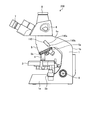
- FIG. 1 is a side view showing a schematic configuration of an upright microscope according to Embodiment 1 of the present invention.
- FIG. 2 is a top view of the erecting microscope of FIG.
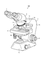
- FIG. 3 is a perspective view of the erected microscope of FIG. 1 as viewed from the front upper right.
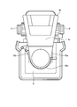
- FIG. 4 is an enlarged perspective view of a handle portion of the erecting microscope of FIG.
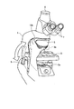
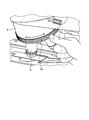
- FIG. 5 is a view for explaining the operation of the erecting microscope of FIG.
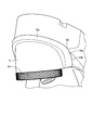
- FIG. 6 is an enlarged perspective view of the handle portion of the erecting microscope according to the first modification of the first embodiment of the present invention.
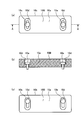
- FIG. 7 is a view for explaining a handle portion according to the second modification of the first embodiment of the present invention.
- FIG. 1 is a side view showing a schematic configuration of an upright microscope according to Embodiment 1 of the present invention.
- FIG. 2 is a top view of the erecting microscope of FIG.
- FIG. 3 is a perspective view of
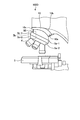
- FIG. 8 is a side view in the vicinity of the revolver of the erecting microscope according to the third modification of the first embodiment of the present invention.
- FIG. 9 is a side view of an erecting microscope according to a second embodiment of the present invention.
- FIG. 10 is a side view of an example of a conventionally used erecting microscope.
- FIG. 11 is a diagram for explaining the switching of the revolver in the erecting microscope of FIG.
- FIG. 1 is a side view showing a schematic configuration of an upright microscope according to Embodiment 1 of the present invention.
- FIG. 2 is a top view of the erecting microscope of FIG.
- FIG. 3 is a perspective view of the erected microscope of FIG. 1 as viewed from the front upper right.
- FIG. 4 is an enlarged perspective view of a handle portion of the erecting microscope of FIG.
- the side on which the examiner is located for observation is referred to as the front side of the upright microscope, and the side opposite to the front side is referred to as the back side of the upright microscope.
- the erecting microscope 100 is provided with a stage 3 on which a sample 2 is placed, a revolver 5 for holding a plurality of objective lenses 4, and a lens barrel 6 in a microscope main body 1.
- the microscope main body 1 is a housing that supports each component of the erected microscope 100, and is configured by a combination of parts made of an aluminum alloy or the like or a plastic material.
- the microscope main body 1 is provided to extend from the stand portion 1 b for holding the stage 3 to the front side of the erected microscope 100, and a revolver 5. And an arm portion 1 c for holding the lens barrel 6.
- the stage 3 on which the sample 2 is placed is moved up and down by a focusing mechanism (not shown) driven in conjunction with the turning operation of the focusing handle 9 provided on the left and right side portions of the microscope main body 1 A match is made. Further, the stage 3 is provided with an XY handle 3a so that the sample 2 can be freely moved in the XY plane.
- the revolver 5 is detachably attached with a plurality of objective lenses 4 having different magnifications.
- the revolver 5 according to the first embodiment is an inward revolver attached to the lower surface of the arm portion 1 c such that the objective lens 4 other than the objective lens 4 on the observation light axis O faces the back side.
- the revolver 5 has a cylindrical shape and has an operation ring 5a whose outer periphery is knurled.
- the front side of the operation ring 5a is an operation unit 5b to which the examiner applies his thumb.
- the lens barrel 6 is detachably attached to the upper surface of the arm portion 1c, and provided with two eyepiece lenses 7 and a TV (television) port 8 for attaching an imaging unit such as a CCD camera.
- an optical system (not shown) for incorporating light collected by the objective lens 4 on the observation optical axis O into the eyepiece 7 or the imaging unit is incorporated in the lens barrel 6.
- the handle portion 10 is a portion on which the finger of the thumb is placed when the examiner rotates the operation ring 5a, and between the revolver 5 which is the upper portion of the operation ring 5a and the arm portion 1c, That is, they are disposed above and behind the revolver 5.
- the handle portion 10 is a position where the other finger can be placed when the speculum operator located on the entire surface of the erecting microscope 100 places the thumb on the operation portion 5b of the operation ring 5a, for example, from the operation portion 5b
- the farthest part of the portion 10 is disposed at a position within 150 mm, preferably about 50 to 100 mm.
- the handle portion 10 has a main body portion 10a which protrudes from the microscope main body 1 and has a projecting shape, and the rear surface side of the main body portion 10a having a projection serves as the handle surface 10b. It is preferable that the protrusion length from the microscope main body 1 of the handle portion 10 is such a length that the other finger is caught, for example, 5 mm or more.
- the hand-handling surface 10b may be uneven for positioning when placing another finger other than the thumb.
- the handle portion 10 is provided on the left and right sides of the microscope main body 1 as viewed from the speculum side, and the handle portions 10 disposed on the left and right are integrally formed by connecting the main body portion 10 a by an annular portion 10 c.
- the handle portion 10 has a color different from that of the microscope main body 1 and the operation ring 5a.
- the handle 10 can be recognized by the color.
- the microscope body 1 is colored white and the operation ring 5a is colored black, the handle portion 10 is colored blue, for example.
- the examiner observes the specimen 2 by the following operation.
- the operating ring 5a of the revolver 5 is operated to switch the objective lens 4 to low magnification (for example, 10 times).
- the XY handle 3a is operated to move the stage 3 in the XY direction, and the sample 2 is screened.
- the operation ring 5a is operated to switch the objective lens 4 to middle and high magnification (for example, 40 times).
- the operation ring 5a is operated to switch the objective lens 4 to middle and high magnification (for example, 40 times).
- the specimen 2 is observed in detail by the middle and high magnification objective lens 4.
- the operation ring 5a is operated to switch the objective lens 4 to low magnification (for example, 10 times) again and repeat from (4) again.
- FIG. 10 is a side view of an example of a conventionally used erecting microscope.
- FIG. 11 is a diagram for explaining the switching of the revolver in the erecting microscope of FIG.
- the focusing handle 9 and the XY handle 3a are disposed at a low position of the erecting microscope 300, that is, at a position close to the desk surface on which the examiner's arm is placed. Therefore, in the above inspection procedure, focusing by the focusing handle 9 of (3) and (6) or the operation of the stage 3 in the XY direction by the XY handle 3a of (4) It is possible to operate with the hands and arms placed on a desk without much movement, which enables stable operation and reduces fatigue associated with the operation.
- the revolver 5 is disposed at a relatively high position of the erecting microscope 300, that is, at a position away from the desk top on which the observer places the arm. Therefore, the switching operation of the objective lens 4 by the operating ring 5a of (1), (5), and (8) in the above-mentioned inspection procedure, the thumb on the front side of the operating ring 5a and the other finger on the operating ring 5a.
- the operation ring 5a is placed on the back side and the operation ring 5a is rotated, or as shown in FIG. 11, only the thumb is placed on the operation ring 5a, and the thumb is moved left and right to rotate the operation ring 5a.
- the upright microscope 100 As shown in FIG. 5, when the thumb is placed on the operation portion 5b on the front side of the operation ring 5a with the elbow attached to the desk, The thumb and other fingers are used to place the handle 10 on the back of the microscope main body 1 where the finger of the user is located, that is, above and behind the revolver 5, to ensure fatigue while reducing the examiner's fatigue. It is possible to operate the operation ring 5a. Further, as shown in FIG.
- the handle portion 10 is disposed at a position where the operation ring 5a and the focusing handle 9 can be operated by raising and lowering the forearm with the elbow attached to a desk, so the operation ring 5a
- the operation of focusing the sample 2 (the above-described operations (5) to (6)) can be easily performed in a state where the sample 2 is observed through the eyepiece 7 it can.
- the handle portion 10 protrudes from the microscope main body 1 and is colored in a color different from that of the microscope main body 1 and the like, the operation, particularly the blind operation, becomes easier with the shape and the color as a clue.
- the handle portion 10 of Embodiment 1 is arrange
- the main body portion 10a of the handle portion 10 has a gentle projecting shape from the annular portion 10c, but as shown in FIG. 6, the handle portion 10A in which the main body portion 10a protrudes from the annular portion 10c at an angle. You can also
- FIG. 7 is a view for explaining the handle portion 10B according to the second modification of the first embodiment of the present invention.
- 7 (a) is a top view of the handle 10B
- FIG. 7 (b) is a cross-sectional view taken along the line AA of FIG. 7 (a)
- FIG. 7 (c) is an attachment of the handle 10B to the microscope main body 1 It is a top view at the time of changing a position.
- the handle portion 10B has a rectangular plate shape, and has opposite long holes 10d at both ends of the main body portion 10a.
- the handle 10B is fixed to the microscope main body 1 through the fixing screw 10e through the counterbore 10d.
- the counterbore hole 10d is a long hole whose long side direction of the handle portion 10B is long, and by shifting the fixing position of the fixing screw 10e to the counterbore hole 10d as shown in FIG. 7C, the microscope main body 1 of the handle portion 10B.
- the mounting position can be changed.
- the handle portion 10B can be disposed at an easy position.
- FIG. 8 is a side view of the vicinity of a revolver of an upright microscope 100D according to a third modification of the first embodiment of the present invention.
- the erecting microscope 100D includes an outward revolver 5D attached to the lower surface of the arm portion 1c such that the objective lens 4 other than the objective lens 4 on the observation optical axis O faces the front side.
- the operation ring 5a of the revolver 5D has a cylindrical portion 5a-1 having a cylindrical shape on the arm portion 1c side and a conical portion 5a-2 having a frusto-conical shape on the objective lens 4 side.
- the outer periphery of the cylindrical portion 5a-1 and the conical portion 5a-2 is knurled.
- the speculum rotates the operation ring 5a by placing the other finger on the handle surface 10b of the handle portion 10 while placing the thumb on the operation portion 5b-2 on the front side of the conical portion 5a-2.
- the conical portion 5a-2 has a truncated cone shape
- the operation portion 5b-2 on the front side is substantially vertical. This facilitates the switching operation of the objective lens 4.
- the examiner places the thumb on the operation unit 5b-1 on the front side of the cylindrical portion 5a-1
- the examiner places the other finger on the back side of the cylindrical portion 5a-1, and the operation ring 5a You can also rotate.
- FIG. 9 is a side view of an upright microscope 200 according to a second embodiment of the present invention.
- the erecting microscope 200 has a handle portion 110 above the rear surface of the revolver 5 at the site where the finger of the thumb is placed when the examiner rotates the operation ring 5a.
- the handle portion 110 has a main portion 110 a having a concave shape recessed from the microscope main body 1, and the front side of the main portion 110 a is a handle surface 110 b.
- the depth of the recess from the microscope main body 1 of the handle portion 110 is preferably such a length as to be caught by the other finger, for example, 5 mm or more. Further, the length of the recess is preferably 50 mm or more, and the width of the recess is preferably 15 mm or more so that the other fingertips enter the recess.
- the handle portion 110 is provided on the left and right sides of the microscope main body 1 or one of the left and right when viewed from the speculum side, and the handle portion 110 and its vicinity are colored differently from the microscope main body 1 and the operation ring 5a. Is preferred.
- the handle portion 110 when the thumb is placed on the operation unit 5b with the elbow attached to the desk, the handle portion 110 is disposed at the site of the microscope main body 1 where the other finger is located. Therefore, it becomes possible to operate the operation ring 5a reliably while reducing fatigue of the speculum observer.
- the handle portion 110 since the handle portion 110 has a concave shape and is colored in a color different from that of the microscope main body 1 or the like, an operation based on the shape and the color, in particular, a blind operation becomes easier.
- the erecting microscope according to the present invention is useful for an erecting microscope used mainly for inspection.
Landscapes
- Physics & Mathematics (AREA)
- General Physics & Mathematics (AREA)
- Optics & Photonics (AREA)
- Chemical & Material Sciences (AREA)
- Analytical Chemistry (AREA)
- Microscoopes, Condenser (AREA)
- Lens Barrels (AREA)
- Structure And Mechanism Of Cameras (AREA)
Abstract
レボルバの切換え操作に伴う検鏡者の負担を軽減することができる正立顕微鏡を提供する。本発明の正立顕微鏡100は、標本2を載置するステージ3と、複数の対物レンズ4を保持し、操作環5aを回転することにより観察光軸上に対物レンズ4を切換え可能なレボルバ5と、観察光軸上の対物レンズ4が集光した光を接眼レンズ7に入射する光学系を有する鏡筒6と、ベース部1aと、ベース部1aの背面側に立設し、ステージ3を保持するスタンド部1bと、スタンド部1bに支持されて前面側に向かって延在し、上部に鏡筒6、下部にレボルバ5が取り付けられるアーム部1cと、を有する顕微鏡本体1と、レボルバ5と鏡筒6との間に位置し、操作環5aを回転する際に親指以外のいずれかの手指を載置する手掛け部10と、を備えることを特徴とする。
Description
本発明は、医学、生物学などの分野に利用される正立顕微鏡に関する。
正立顕微鏡は、医学、生物学をはじめ、その他の分野において研究、検査、教育用途として利用されている(例えば、特許文献1または2参照)。検査用途では、主にスライド標本を多数拡大観察して、検査する場合がある。スライド標本を検査する際は、4倍~10倍の低倍の対物レンズを使用し、スライド標本を設置したステージのXYハンドルによりスライド標本を移動させながら観察する。この時、標本として組織や細胞の異常、細菌の有無といった注目すべき箇所がある場合は、レボルバの操作環を回転することにより、低倍の対物レンズから20倍~100倍の中高倍の対物レンズに切替えて観察が行われる。
近年、顕微鏡の機能として鮮明な観察像が求められるだけでなく、顕微鏡の各部の操作性や、操作に伴う疲労軽減に対する要求が高まっている。特に検査用途では、1日に多数のスライド標本を検査する場合があるため、その要求は強くなっている。
特許文献1および2の正立顕微鏡では、図10に示すように、焦準ハンドル9や、XYハンドル3aは、机上面から低い位置に配置されているため、腕や手の側面を机上に置いた状態で操作することができる。したがって、安定したハンドル操作が可能となり、操作に伴う疲労も軽減することができる。
しかしながら、レボルバ5は机上面から高い位置に配置されているため、検鏡者が図11に示すように操作環5aを指で回して対物レンズ4を切り替える際、腕を上げた状態、または肘をついて手を上げた状態で操作環5aを回すことになり、操作に対する負担軽減については何ら考慮されていなかった。その結果、特許文献1、2の正立顕微鏡では、検鏡者の負担が大きいものであった。
本発明は、上記に鑑みてなされたものであって、レボルバの切換え操作に伴う検鏡者の負担を軽減することができる正立顕微鏡を提供することを目的とする。
上述した課題を解決し、目的を達成するために、本発明の正立顕微鏡は、標本を載置するステージと、複数の対物レンズを保持し、操作環を回転することにより観察光軸上に前記対物レンズを切換え可能なレボルバと、観察光軸上の前記対物レンズが集光した光を接眼レンズに入射する光学系を有する鏡筒と、ベース部と、ベース部の背面側に立設し、前記ステージを保持するスタンド部と、前記スタンド部に支持されて前面側に向かって延在し、上部に前記鏡筒、下部に前記レボルバが取り付けられるアーム部と、を有する顕微鏡本体と、前記レボルバと前記鏡筒との間に位置し、前記操作環を回転する際に検鏡者の親指以外のいずれかの手指を載置するための手掛け部と、を備えることを特徴とする。
また、本発明にかかる正立顕微鏡は、上記発明において、前記手掛け部は、前記顕微鏡本体から突出する突起状をなすことを特徴とする。
また、本発明にかかる正立顕微鏡は、上記発明において、前記手掛け部は、前記顕微鏡本体から凹んだ凹形状をなすことを特徴とする。
また、本発明にかかる正立顕微鏡は、上記発明において、前記手掛け部は、手指を載置する面がなめらかな凹凸形状をなすことを特徴とする。
また、本発明にかかる正立顕微鏡は、上記発明において、前記手掛け部は、前記レボルバと前記アーム部との間であって、当該正立顕微鏡の左右のいずれか一方、または左右両方に位置することを特徴とする。
また、本発明にかかる正立顕微鏡は、上記発明において、前記手掛け部は、当該正立顕微鏡から着脱可能であって、前記手掛け部の前記操作環からの距離が変更可能であることを特徴とする。
また、本発明にかかる正立顕微鏡は、上記発明において、前記レボルバは、複数の前記対物レンズが前面側を向くように前記アーム部に対し取り付けられる外向きレボルバであって、前記操作環は、前記アーム部側に位置し円筒形状をなす円筒部と、前記対物レンズ側に位置し円錐台形状をなす円錐部と、を備えることを特徴とする。
本発明にかかる正立顕微鏡は、レボルバの操作環の近傍に、操作環を回転する際に検鏡者の親指以外のいずれかの手指を載置する手掛け部を設けることにより、対物レンズの切換えを容易とするとともに、検鏡者の疲労を軽減することができる。
以下に、本発明の実施の形態にかかる正立顕微鏡を図面に基づいて詳細に説明する。なお、この実施例によりこの発明が限定されるものではない。さらに、図面の記載において、同一部分には同一の符号を付している。さらにまた、図面は、模式的なものであり、各部材の厚みと幅との関係、各部材の比率等は、現実と異なることに留意する必要がある。また、図面の相互間においても、互いの寸法や比率が異なる部分が含まれている。
(実施の形態1)
図1は、本発明の実施の形態1にかかる正立顕微鏡の概略構成を示す側面図である。図2は、図1の正立顕微鏡の上面図である。図3は、図1の正立顕微鏡を前面右上方から見た斜視図である。図4は、図1の正立顕微鏡の手掛け部の拡大斜視図である。本明細書において、検鏡者が観察のために位置する側を正立顕微鏡の前面側、前面と対向する側を正立顕微鏡の背面側とする。
図1は、本発明の実施の形態1にかかる正立顕微鏡の概略構成を示す側面図である。図2は、図1の正立顕微鏡の上面図である。図3は、図1の正立顕微鏡を前面右上方から見た斜視図である。図4は、図1の正立顕微鏡の手掛け部の拡大斜視図である。本明細書において、検鏡者が観察のために位置する側を正立顕微鏡の前面側、前面と対向する側を正立顕微鏡の背面側とする。
正立顕微鏡100は、顕微鏡本体1に、標本2を載置するステージ3、複数の対物レンズ4を保持するレボルバ5、および鏡筒6が設けられている。顕微鏡本体1は、正立顕微鏡100の各構成部材を支持する筐体であり、アルミ合金等や、プラスチック材料から形成されたパーツの組み合わせにより構成されている。顕微鏡本体1は、図示しない照明光学系を内設するベース部1aと、ステージ3を保持するスタンド部1bと、スタンド部1bから正立顕微鏡100の前面側に延出させて設けられ、レボルバ5および鏡筒6を保持するアーム部1cとを有する。
標本2を載置するステージ3は、顕微鏡本体1の左右の側面部に突設された焦準ハンドル9の回動操作に連動して駆動される図示しない焦準機構によって、昇降移動され、ピント合わせがなされる。また、ステージ3は、XYハンドル3aを備え、標本2をXY平面内で自在に動かすことが可能とされている。
レボルバ5は、倍率の異なる複数の対物レンズ4が着脱自在に取り付けられている。実施の形態1のレボルバ5は、観察光軸O上の対物レンズ4以外の対物レンズ4が、背面側を向くようにアーム部1cの下面に取り付けられる内向きレボルバである。レボルバ5は、円筒形状をなし、外周がローレット加工されている操作環5aを有する。操作環5aの前面側が、検鏡者が親指を添える操作部5bである。
鏡筒6は、アーム部1cの上面に着脱自在に取り付けられており、2つの接眼レンズ7と、CCDカメラ等の撮像部を取り付けるためのTV(テレビジョン)ポート8が設けられている。また、鏡筒6の内部には、観察光軸O上の対物レンズ4が集光した光を、接眼レンズ7、または撮像部に入射する光学系(図示しない)が内蔵されている。正立顕微鏡100により観察する際、鏡筒6は接眼レンズ7が、正立顕微鏡100の前面側になるよう取り付けられるが、鏡筒6は回転可能であり、接眼レンズ7が正立顕微鏡100の背面側を向くように回転させ、背面側から標本を観察したり、収納することもできる。
手掛け部10は、検鏡者が操作環5aを回転する際に親指以外のいずれかの手指を載置する部位であって、操作環5aの上部であるレボルバ5とアーム部1cとの間、すなわち、レボルバ5の上方、かつ背面側に配置されている。手掛け部10は、正立顕微鏡100の全面に位置する検鏡者が、操作環5aの操作部5bに親指を添えた際に、他の指が載置できる位置、例えば、操作部5bから手掛け部10の最遠部が150mm以内、好ましくは50~100mm程度の位置に配置される。
手掛け部10は、顕微鏡本体1から突出して突起状をなす本体部10aを有し、突起をなす本体部10aの背面側が手掛け面10bとなる。手掛け部10の顕微鏡本体1からの突出長さは、他の指が引っ掛かるだけの長さ、たとえば、5mm以上であることが好ましい。手掛け面10bは、親指以外の他の指を載置する際の位置決め用に凹凸状としてもよい。手掛け部10は、検鏡者側から見て顕微鏡本体1の左右両側に設けられ、左右に配置される手掛け部10は、本体部10aが環状部10cにより連結されて一体として形成されている。手掛け部10は、顕微鏡本体1および操作環5aと異なる色彩とすることが好ましい。手掛け部10を、顕微鏡本体1および操作環5aと異なる色に彩色することにより、色彩により手掛け部10を認識することが可能となる。一般に、顕微鏡本体1は白色、操作環5aは黒色に彩色されるため、手掛け部10は、例えば青色に彩色される。
通常、スライドガラスを用いた標本2の検査では、検鏡者は以下の操作により標本2の観察を行う。
(1)レボルバ5の操作環5aを操作して対物レンズ4を低倍(たとえば、10倍)に切換える。
(2)標本2をステージ3の上面に設置する。
(3)焦準ハンドル9を操作して標本2にピントを合わせる。
(4)接眼レンズ7で観察しながら、XYハンドル3aを操作してステージ3をXY方向に移動し、標本2をスクリーニングする。
(5)標本2上に注目すべき箇所がある場合には、操作環5aを操作して対物レンズ4を中高倍(たとえば、40倍)に切換える。
(6)焦準ハンドル9を操作して標本2に再度ピントを合わせる。
(7)中高倍の対物レンズ4で標本2を詳細に観察する。
(8)操作環5aを操作して対物レンズ4を再度低倍(たとえば、10倍)に切換えて、再度(4)から繰り返す。
(1)レボルバ5の操作環5aを操作して対物レンズ4を低倍(たとえば、10倍)に切換える。
(2)標本2をステージ3の上面に設置する。
(3)焦準ハンドル9を操作して標本2にピントを合わせる。
(4)接眼レンズ7で観察しながら、XYハンドル3aを操作してステージ3をXY方向に移動し、標本2をスクリーニングする。
(5)標本2上に注目すべき箇所がある場合には、操作環5aを操作して対物レンズ4を中高倍(たとえば、40倍)に切換える。
(6)焦準ハンドル9を操作して標本2に再度ピントを合わせる。
(7)中高倍の対物レンズ4で標本2を詳細に観察する。
(8)操作環5aを操作して対物レンズ4を再度低倍(たとえば、10倍)に切換えて、再度(4)から繰り返す。
図10は、従来使用される正立顕微鏡の一例の側面図である。図11は、図10の正立顕微鏡でのレボルバの切換えを説明する図である。図10に示すように、焦準ハンドル9およびXYハンドル3aは、正立顕微鏡300の低い位置、すなわち検鏡者の腕を載置する机上面から近い位置に配置されている。したがって、上記の検査手順における、(3)、(6)の焦準ハンドル9によるピント合わせや、(4)のXYハンドル3aによるステージ3のXY方向の操作は、検鏡者は手や腕をあまり動かすことなく、手や腕を机上に置いた状態で操作することができ、安定した操作が可能となるとともに、操作に伴う疲労が小さい。
一方、レボルバ5は、正立顕微鏡300の比較的高い位置、すなわち検鏡者が腕を載置する机上面から離れた位置に配置されている。したがって、上記の検査手順における、(1)、(5)、(8)の操作環5aによる対物レンズ4の切換え操作は、親指を操作環5aの前面側に、他の指を操作環5aの背面側に載置して操作環5aを回転するか、または、図11に示すように、親指のみを操作環5aに載置し、親指を左右に動かして操作環5aを回転する。親指および他の指で操作環5aを操作する場合、検鏡者は腕を上げた状態で操作するため疲労が大きくなる。また、親指のみで操作環5aを操作する場合、肘を机上につき手を上げた状態で行うが、腕を上げた状態での操作よりは疲労は低減できるものの、レボルバ5はクリック機構を採用するため、クリックアウト-摺動回転-クリックインという一連の操作において、クリックインの際にクリックを乗り越えないよう微妙な操作感が必要とされる。
これに対し、本実施の形態1にかかる正立顕微鏡100では、図5に示すように、肘を机上についた状態で操作環5aの前面側の操作部5bに親指を載置した際、他の指が位置する顕微鏡本体1の部位、すなわち、レボルバ5の上方、かつ背面側に手掛け部10を配置するため、親指と他の指を使用し、検鏡者の疲労を軽減しながら、確実に操作環5aの操作を行うことが可能となる。また、手掛け部10は、図5に示すように、肘を机上についた状態で前腕を上げ下げすることにより、操作環5aおよび焦準ハンドル9の操作ができる位置に配置されるため、操作環5aによる対物レンズ4の切換えの後、標本2にピントを合わせる操作(上記の(5)から(6)の操作)を、接眼レンズ7を介して標本2を観察した状態で、容易に行うことができる。また、手掛け部10は、顕微鏡本体1から突出し、かつ顕微鏡本体1等とは異なる色に彩色されているため、形状および彩色を手掛かりとして操作、特にブラインド操作がより容易となる。
なお、実施の形態1の手掛け部10は、左右両側に配置されているが、検鏡者から見て左右のいずれか一方に形成されていてもよい。
また、手掛け部10の本体部10aは、環状部10cからなだらかな突起状をなしているが、図6に示すように、環状部10cから本体部10aが角度をなして突起する手掛け部10Aとすることもできる。
さらに、手掛け部10は、顕微鏡本体1から着脱可能とすることもできる。図7は、本発明の実施の形態1の変形例2にかかる手掛け部10Bを説明する図である。図7(a)は手掛け部10Bの上面図、図7(b)は、図7(a)のA-A線断面図、図7(c)は、手掛け部10Bの顕微鏡本体1への取付け位置を変更した場合の上面図である。
手掛け部10Bは、矩形板状をなし、本体部10aの両端部に長穴のザグリ穴10dを有する。このザグリ穴10dに固定ビス10eを通して、顕微鏡本体1に手掛け部10Bを固定する。ザグリ穴10dは、手掛け部10Bの短辺方向が長い長穴であり、ザグリ穴10dに対する固定ビス10eの固定位置を、図7(c)のようにずらすことにより、手掛け部10Bの顕微鏡本体1への取付け位置を変更することができる。手掛け部10Bの顕微鏡本体1への取付け位置を変更することにより、操作環5aの操作部5bから手掛け部10Bの手掛け面10bまでの距離を変更することができるので、検鏡者は、操作し易い位置に手掛け部10Bを配置することができる。
上記の実施の形態1および変形例では、内向きレボルバを使用する場合について説明したが、外向きレボルバを使用する場合も、手掛け部を設けることにより検鏡者の疲労を軽減することができる。図8は、本発明の実施の形態1の変形例3にかかる正立顕微鏡100Dのレボルバ近傍の側面図である。
正立顕微鏡100Dは、観察光軸O上の対物レンズ4以外の対物レンズ4が、前面側を向くようにアーム部1cの下面に取り付けられる外向きのレボルバ5Dを備える。
レボルバ5Dの操作環5aは、アーム部1c側の円筒形状をなす円筒部5a-1と、対物レンズ4側の円錐台形状をなす円錐部5a-2と、を有する。円筒部5a-1および円錐部5a-2の外周は、ローレット加工されている。
検鏡者は、円錐部5a-2の前面側の操作部5b-2に親指を載置しながら、手掛け部10の手掛け面10bに他の指を載置することにより、操作環5aを回転する。円錐部5a-2は円錐台形状をなしているため、前面側の操作部5b-2は略鉛直となる。これにより、対物レンズ4の切換え操作が容易となる。また、検鏡者は、円筒部5a-1の前面側の操作部5b-1に親指を載置しながら、他の指を円筒部5a-1の背面側に載置して、操作環5aを回転することもできる。
(実施の形態2)
実施の形態2にかかる正立顕微鏡は、手掛け部が顕微鏡本体から凹んだ凹形状をなしている。図9は、本発明の実施の形態2にかかる正立顕微鏡200の側面図である。
実施の形態2にかかる正立顕微鏡は、手掛け部が顕微鏡本体から凹んだ凹形状をなしている。図9は、本発明の実施の形態2にかかる正立顕微鏡200の側面図である。
正立顕微鏡200は、検鏡者が操作環5aを回転する際に親指以外のいずれかの手指を載置する部位、すなわち、レボルバ5の上方、かつ背面側に手掛け部110を有する。手掛け部110は、顕微鏡本体1から凹んだ凹形状をなす本体部110aを有し、本体部110aの前面側が手掛け面110bとなる。手掛け部110の顕微鏡本体1からの凹部の深さは、他の指が引っ掛かるだけの長さ、たとえば、5mm以上であることが好ましい。また、他の指先が凹部内に入るように、凹部の長さは50mm以上、凹部の幅は15mm以上とすることが好ましい。
手掛け部110は、検鏡者側から見て顕微鏡本体1の左右両側、または左右のいずれか一方に設けられ、手掛け部110およびその近傍を、顕微鏡本体1および操作環5aと異なる色彩とすることが好ましい。
本実施の形態2にかかる正立顕微鏡200では、手掛け部110が、肘を机上についた状態で操作部5bに親指を載置した際、他の指が位置する顕微鏡本体1の部位に配置されるため、検鏡者の疲労を軽減しながら、確実に操作環5aの操作を行うことが可能となる。また、手掛け部110は、凹部形状をなし、かつ顕微鏡本体1等とは異なる色に彩色されているため、形状および彩色を手掛かりとした操作、特にブラインド操作がより容易となる。
以上のように、本発明にかかる正立顕微鏡は、主として検査用に使用される正立顕微鏡に有用である。
1 顕微鏡本体
1a ベース部
1b スタンド部
1c アーム部
2 標本
3 ステージ
4 対物レンズ
5 レボルバ
5a 操作環
5a-1 円筒部
5a-2 円錐部
5b、5b-1、5b-2 操作部
6 鏡筒
7 接眼レンズ
8 TVポート
9 焦準ハンドル
10、10A、10B、110 手掛け部
10a 本体部
10b 手掛け面
10c 環状部
10d ザグリ穴
10e 固定ビス
100、100D、200、300 正立顕微鏡
1a ベース部
1b スタンド部
1c アーム部
2 標本
3 ステージ
4 対物レンズ
5 レボルバ
5a 操作環
5a-1 円筒部
5a-2 円錐部
5b、5b-1、5b-2 操作部
6 鏡筒
7 接眼レンズ
8 TVポート
9 焦準ハンドル
10、10A、10B、110 手掛け部
10a 本体部
10b 手掛け面
10c 環状部
10d ザグリ穴
10e 固定ビス
100、100D、200、300 正立顕微鏡
Claims (7)
- 標本を載置するステージと、
複数の対物レンズを保持し、操作環を回転することにより観察光軸上に前記対物レンズを切換え可能なレボルバと、
観察光軸上の前記対物レンズが集光した光を接眼レンズに入射する光学系を有する鏡筒と、
ベース部と、ベース部の背面側に立設し、前記ステージを保持するスタンド部と、前記スタンド部に支持されて前面側に向かって延在し、上部に前記鏡筒、下部に前記レボルバが取り付けられるアーム部と、を有する顕微鏡本体と、
前記レボルバと前記鏡筒との間に位置し、前記操作環を回転する際に検鏡者の親指以外のいずれかの手指を載置するための手掛け部と、
を備えることを特徴とする正立顕微鏡。 - 前記手掛け部は、前記顕微鏡本体から突出する突起状をなすことを特徴とする請求項1に記載の正立顕微鏡。
- 前記手掛け部は、前記顕微鏡本体から凹んだ凹形状をなすことを特徴とする請求項1に記載の正立顕微鏡。
- 前記手掛け部は、手指を載置する面がなめらかな凹凸形状をなすことを特徴とする請求項1~3のいずれか一つに記載の正立顕微鏡。
- 前記手掛け部は、前記レボルバと前記アーム部との間であって、当該正立顕微鏡の左右のいずれか一方、または左右両方に位置することを特徴とする請求項1~4のいずれか一つに記載の正立顕微鏡。
- 前記手掛け部は、当該正立顕微鏡から着脱可能であって、前記手掛け部の前記操作環からの距離が変更可能であることを特徴とする請求項1または2に記載の正立顕微鏡。
- 前記レボルバは、複数の前記対物レンズが前面側を向くように前記アーム部に対し取り付けられる外向きレボルバであって、
前記操作環は、前記アーム部側に位置し円筒形状をなす円筒部と、前記対物レンズ側に位置し円錐台形状をなす円錐部と、を備えることを特徴とする請求項1に記載の正立顕微鏡。
Priority Applications (2)
| Application Number | Priority Date | Filing Date | Title |
|---|---|---|---|
| CN201780017417.0A CN108780219B (zh) | 2016-03-16 | 2017-03-03 | 正像显微镜 |
| US16/043,087 US20180329174A1 (en) | 2016-03-16 | 2018-07-23 | Upright microscope |
Applications Claiming Priority (2)
| Application Number | Priority Date | Filing Date | Title |
|---|---|---|---|
| JP2016052757A JP6637350B2 (ja) | 2016-03-16 | 2016-03-16 | 正立顕微鏡 |
| JP2016-052757 | 2016-03-16 |
Related Child Applications (1)
| Application Number | Title | Priority Date | Filing Date |
|---|---|---|---|
| US16/043,087 Continuation US20180329174A1 (en) | 2016-03-16 | 2018-07-23 | Upright microscope |
Publications (1)
| Publication Number | Publication Date |
|---|---|
| WO2017159404A1 true WO2017159404A1 (ja) | 2017-09-21 |
Family
ID=59851652
Family Applications (1)
| Application Number | Title | Priority Date | Filing Date |
|---|---|---|---|
| PCT/JP2017/008505 Ceased WO2017159404A1 (ja) | 2016-03-16 | 2017-03-03 | 正立顕微鏡 |
Country Status (4)
| Country | Link |
|---|---|
| US (1) | US20180329174A1 (ja) |
| JP (1) | JP6637350B2 (ja) |
| CN (1) | CN108780219B (ja) |
| WO (1) | WO2017159404A1 (ja) |
Families Citing this family (4)
| Publication number | Priority date | Publication date | Assignee | Title |
|---|---|---|---|---|
| CN109856789B (zh) * | 2019-02-26 | 2021-10-22 | 中国科学院苏州生物医学工程技术研究所 | 高内涵超分辨一体化显微成像系统及方法 |
| DE102021001403A1 (de) | 2021-03-16 | 2022-09-22 | Systamatec GmbH | Vorrichtung zum Aufnehmen und Positionieren von bis zu 4 optischen Objektiven über einem Beobachtungspunkt mit einer zentralen Drehachse in Mikroskop Anwendungen |
| PL245406B1 (pl) | 2021-03-31 | 2024-07-22 | Univ Warszawski | Mikroskop optyczny |
| USD1068896S1 (en) * | 2024-07-03 | 2025-04-01 | Shangrao Tieniu Technology Co., Ltd | Microscope |
Citations (2)
| Publication number | Priority date | Publication date | Assignee | Title |
|---|---|---|---|---|
| US20080198447A1 (en) * | 2004-03-31 | 2008-08-21 | Swift Instruments, Inc. | Microscope with Adjustable Stage |
| JP2015222381A (ja) * | 2014-05-23 | 2015-12-10 | オリンパス株式会社 | 顕微鏡装置 |
Family Cites Families (5)
| Publication number | Priority date | Publication date | Assignee | Title |
|---|---|---|---|---|
| US5337177A (en) * | 1989-09-13 | 1994-08-09 | Nikon Corporation | Microscope |
| US5198927A (en) * | 1989-09-20 | 1993-03-30 | Yale University | Adapter for microscope |
| JPH09179036A (ja) * | 1995-12-27 | 1997-07-11 | Olympus Optical Co Ltd | 正立型顕微鏡 |
| AU2008343383B2 (en) * | 2007-12-27 | 2013-08-29 | Cytyc Corporation | Apparatus for single-handed control of microscope functions |
| CN204462532U (zh) * | 2015-03-24 | 2015-07-08 | 管星 | 创新型电子检验显微镜 |
-
2016
- 2016-03-16 JP JP2016052757A patent/JP6637350B2/ja active Active
-
2017
- 2017-03-03 CN CN201780017417.0A patent/CN108780219B/zh active Active
- 2017-03-03 WO PCT/JP2017/008505 patent/WO2017159404A1/ja not_active Ceased
-
2018
- 2018-07-23 US US16/043,087 patent/US20180329174A1/en not_active Abandoned
Patent Citations (2)
| Publication number | Priority date | Publication date | Assignee | Title |
|---|---|---|---|---|
| US20080198447A1 (en) * | 2004-03-31 | 2008-08-21 | Swift Instruments, Inc. | Microscope with Adjustable Stage |
| JP2015222381A (ja) * | 2014-05-23 | 2015-12-10 | オリンパス株式会社 | 顕微鏡装置 |
Also Published As
| Publication number | Publication date |
|---|---|
| JP6637350B2 (ja) | 2020-01-29 |
| JP2017167353A (ja) | 2017-09-21 |
| CN108780219A (zh) | 2018-11-09 |
| CN108780219B (zh) | 2021-09-14 |
| US20180329174A1 (en) | 2018-11-15 |
Similar Documents
| Publication | Publication Date | Title |
|---|---|---|
| US11147443B2 (en) | Surgical visualization systems and displays | |
| JP6521982B2 (ja) | 手術可視化システム及びディスプレイ | |
| US20160202460A1 (en) | 3D Microscopy With Illumination Engineering | |
| WO2017159404A1 (ja) | 正立顕微鏡 | |
| CN203720438U (zh) | 一种显微镜 | |
| US20230355346A1 (en) | Surgical microscope having assistant's device | |
| CN104820281A (zh) | 一种多功能生物显微镜 | |
| JP7025530B2 (ja) | 広領域の共焦点及び多光子顕微鏡で用いる動的フォーカス・ズームシステム | |
| JP2014059413A (ja) | 顕微鏡 | |
| JP2021513668A (ja) | 広領域の共焦点及び多光子顕微鏡で用いる動的フォーカス・ズームシステム | |
| KR101527925B1 (ko) | 현미경 모듈 | |
| EP3465344A1 (en) | Imaging adapter for microscope and portable elecronic device | |
| WO2022062383A1 (zh) | 一种显微手术辅助装置 | |
| CN202133814U (zh) | 显微镜头装置 | |
| CN211043798U (zh) | 一种共目镜显微望远镜 | |
| JP2019076329A (ja) | 前置レンズ装置及び眼科用顕微鏡 | |
| WO2018021717A1 (ko) | 내시경 현미경 결합 모듈 | |
| JP2000338418A (ja) | 顕微鏡 | |
| CN108780220B (zh) | 显微镜 | |
| JP2007292935A (ja) | 実体顕微鏡 | |
| JP2009282055A (ja) | 顕微鏡システム | |
| JP2019114503A (ja) | 照明装置、顕微鏡装置 | |
| Yamashita | 8K ultra-high definition medical application: development of new endoscope and microscope | |
| JP3140205U (ja) | 光学機器 | |
| JP2019090968A (ja) | 顕微鏡 |
Legal Events
| Date | Code | Title | Description |
|---|---|---|---|
| NENP | Non-entry into the national phase |
Ref country code: DE |
|
| 121 | Ep: the epo has been informed by wipo that ep was designated in this application |
Ref document number: 17766407 Country of ref document: EP Kind code of ref document: A1 |
|
| 122 | Ep: pct application non-entry in european phase |
Ref document number: 17766407 Country of ref document: EP Kind code of ref document: A1 |