WO2017159342A1 - 紫外線放射装置 - Google Patents
紫外線放射装置 Download PDFInfo
- Publication number
- WO2017159342A1 WO2017159342A1 PCT/JP2017/007694 JP2017007694W WO2017159342A1 WO 2017159342 A1 WO2017159342 A1 WO 2017159342A1 JP 2017007694 W JP2017007694 W JP 2017007694W WO 2017159342 A1 WO2017159342 A1 WO 2017159342A1
- Authority
- WO
- WIPO (PCT)
- Prior art keywords
- ozone
- ultraviolet
- generation layer
- radiation device
- ozone generation
- Prior art date
- Legal status (The legal status is an assumption and is not a legal conclusion. Google has not performed a legal analysis and makes no representation as to the accuracy of the status listed.)
- Ceased
Links
Images


Classifications
-
- A—HUMAN NECESSITIES
- A61—MEDICAL OR VETERINARY SCIENCE; HYGIENE
- A61L—METHODS OR APPARATUS FOR STERILISING MATERIALS OR OBJECTS IN GENERAL; DISINFECTION, STERILISATION OR DEODORISATION OF AIR; CHEMICAL ASPECTS OF BANDAGES, DRESSINGS, ABSORBENT PADS OR SURGICAL ARTICLES; MATERIALS FOR BANDAGES, DRESSINGS, ABSORBENT PADS OR SURGICAL ARTICLES
- A61L2/00—Disinfection or sterilisation of materials or objects, in general; Accessories therefor
- A61L2/02—Disinfection or sterilisation of materials or objects, in general; Accessories therefor using physical processes
- A61L2/08—Radiation
- A61L2/10—Ultraviolet [UV] radiation
-
- A—HUMAN NECESSITIES
- A61—MEDICAL OR VETERINARY SCIENCE; HYGIENE
- A61N—ELECTROTHERAPY; MAGNETOTHERAPY; RADIATION THERAPY; ULTRASOUND THERAPY
- A61N5/00—Radiation therapy
- A61N5/06—Radiation therapy using light
-
- B—PERFORMING OPERATIONS; TRANSPORTING
- B01—PHYSICAL OR CHEMICAL PROCESSES OR APPARATUS IN GENERAL
- B01J—CHEMICAL OR PHYSICAL PROCESSES, e.g. CATALYSIS OR COLLOID CHEMISTRY; THEIR RELEVANT APPARATUS
- B01J19/00—Chemical, physical or physico-chemical processes in general; Their relevant apparatus
- B01J19/08—Processes employing the direct application of electric or wave energy, or particle radiation; Apparatus therefor
- B01J19/12—Processes employing the direct application of electric or wave energy, or particle radiation; Apparatus therefor employing electromagnetic waves
-
- H—ELECTRICITY
- H01—ELECTRIC ELEMENTS
- H01J—ELECTRIC DISCHARGE TUBES OR DISCHARGE LAMPS
- H01J61/00—Gas-discharge or vapour-discharge lamps
- H01J61/02—Details
- H01J61/30—Vessels; Containers
- H01J61/34—Double-wall vessels or containers
-
- H—ELECTRICITY
- H01—ELECTRIC ELEMENTS
- H01J—ELECTRIC DISCHARGE TUBES OR DISCHARGE LAMPS
- H01J65/00—Lamps without any electrode inside the vessel; Lamps with at least one main electrode outside the vessel
Definitions
- the present invention relates to an ultraviolet radiation device, and more particularly to an ultraviolet radiation device suitably used for sterilization treatment and deodorization treatment of skin and the like.
- ultraviolet rays are suitably used for sterilization treatment of skin and the like, deodorization treatment, and organic contaminant removal treatment.
- an ultraviolet light source an excimer lamp is widely known (for example, see Patent Document 1).
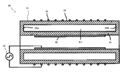
- an excimer lamp As an excimer lamp, as shown in FIG. 6, it is smaller than the inner diameter of a cylindrical outer tube 22 and the outer tube 22 arranged along the tube axis in the outer tube 22.
- An arc tube 21 having a double tube structure made of synthetic quartz glass having a cylindrical inner tube 23 having an outer diameter is provided.
- both end portions of the outer tube 22 and the inner tube 23 are joined by the sealing wall members 24 ⁇ / b> A and 24 ⁇ / b> B, and an annular inner space S ⁇ b> 1 is formed between the outer tube 22 and the inner tube 23.
- the internal space S1 is filled with a discharge gas.
- the arc tube 21 is provided with a net-like outer electrode 25 on the outer peripheral surface of the outer tube 22, and a film-like inner electrode 26 is provided on the inner peripheral surface of the inner tube 23. 26 are each connected to a high frequency power source 19. In this excimer lamp 20, when a high frequency high voltage is applied between the outer electrode 25 and the inner electrode 26 by the high frequency power source 19, excimer discharge is generated in the internal space S1, and excimer light is emitted.
- ultraviolet rays having a wavelength of around 200 nm specifically, ultraviolet rays having a wavelength of approximately 200 to 250 nm are used.
- the excimer lamp can adjust the wavelength characteristics (wavelength range) of the light emitted depending on the type of discharge gas. Therefore, by using an appropriate gas as the discharge gas, the excimer lamp has a wavelength around 200 nm. Radiation light (ultraviolet light) having a center wavelength can be obtained.
- a discharge gas for obtaining synchrotron radiation having a central wavelength in the vicinity of a wavelength of 200 nm
- argon fluoride (ArF) gas for example, argon fluoride (ArF) gas (radiation obtained) (Central wavelength of light 193 nm), krypton bromide (KrBr) gas (central wavelength of the obtained synchrotron radiation 207 nm), krypton chloride (KrCl) gas (central wavelength of the synchrotron radiation obtained 222 nm), krypton fluoride (KrF) gas
- the obtained synchrotron radiation has a central wavelength of 248 nm), xenon iodide (XeI) gas (the central wavelength of the synchrotron radiation obtained is 253 nm), and chlorine (Cl 2 ) gas (the central wavelength of the synchrotron radiation obtained is 259 nm).
- the emitted light of the excimer lamp can be regarded as monochromatic light in practice, and its spectrum (radiation spectrum) is a line spectrum, but has a certain spectral line width. Therefore, the emitted light of the excimer lamp includes light having a longer wavelength than the center wavelength and light having a shorter wavelength than the center wavelength, as well as light having the center wavelength. Therefore, in an excimer lamp in which a specific discharge gas is sealed (hereinafter also referred to as “specific excimer lamp”), when the emitted light contains ultraviolet light having a wavelength of less than 190 nm, ozone (O 3 ) appear.
- ozone-generating ultraviolet rays ultraviolet rays having a wavelength of less than 190 nm are absorbed by oxygen and generate ozone (hereinafter also referred to as “ozone-generating ultraviolet rays”).
- ozone is efficiently generated by emitting ozone-generating ultraviolet rays in an oxygen-existing atmosphere. Therefore, when the specific excimer lamp is turned on in the air atmosphere, ozone is generated by absorbing the ozone-generating ultraviolet rays into the oxygen in the air.
- high-concentration ozone adversely affects the human body, when using a specific excimer lamp particularly in a living space, for example, when using an excimer lamp for sterilization of the skin, for example. Needs to suppress the generation of ozone.
- the inventors of the present invention have studied using a glass tube or a coating agent used as a vacuum ultraviolet ray-cutting member as a constituent material of an arc tube of a specific excimer lamp. Specifically, the use of a glass tube doped with titanium oxide (TiO 2 ), which is generally used as a vacuum ultraviolet ray-cutting member, was examined as a constituent material of the arc tube of the specific excimer lamp. However, since titanium oxide has a characteristic of absorbing not only ozone-generated ultraviolet rays but also ultraviolet rays having a wavelength of 200 nm, ultraviolet rays having a wavelength of 200 nm generated in the inner space of the arc tube are caused by the arc tube (titanium oxide).
- the present invention has been found as a result of the inventors of the present invention conducting research on ultraviolet radiation means that can be suitably used in an air atmosphere, and the object thereof is to be used in an air atmosphere. Even in such a case, it is an object to provide an ultraviolet radiation device capable of suppressing the generation of ozone in the ambient atmosphere outside the device and emitting ultraviolet rays having a wavelength of around 200 nm with high emission intensity.
- the ultraviolet radiation device of the present invention includes an ultraviolet light source that emits light including ultraviolet light having a wavelength that is absorbed by oxygen and generates ozone, and ultraviolet light that is disposed apart from the ultraviolet light source. It has an ozone generation layer forming member for forming an ozone generation layer with a gas that absorbs and generates ozone, The light from the ultraviolet light source is emitted through the ozone generation layer forming member.
- the ozone generation layer forming member constitutes a mantle tube, and the mantle tube is disposed so as to surround the ultraviolet light source.
- the ultraviolet light source is preferably an excimer lamp.
- the ultraviolet light source is preferably an LED element.
- the ozone generation layer is preferably an air layer, and the thickness of the air layer is preferably 20 mm or less.
- the ozone generation layer made of a gas that absorbs ultraviolet rays and generates ozone emits light including ultraviolet rays having a wavelength that is absorbed by oxygen and generates ozone (ozone-generating ultraviolet rays).
- the ozone generating layer forming member, and light from the ultraviolet light source is emitted through the ozone generating layer forming member. Therefore, the ozone generation ultraviolet rays contained in the light from the ultraviolet light source are selectively absorbed in the ozone generation layer.
- the emission intensity of ozone-generated ultraviolet light can be reduced without greatly reducing the emission intensity of ultraviolet light other than ozone-generated ultraviolet light.
- the ultraviolet radiation device of the present invention even when used in an air atmosphere, generation of ozone in the ambient atmosphere outside the device can be suppressed, and ultraviolet light having a wavelength of around 200 nm can be emitted with high emission intensity. Can be emitted.
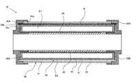
- FIG. 1 is an explanatory sectional view showing an example of the configuration of the first ultraviolet radiation device of the present invention.
- the first ultraviolet radiation device 10 includes an ultraviolet light source composed of a straight tubular excimer lamp 20 and a long cylindrical mantle member 30 disposed so as to surround the excimer lamp 20.
- the outer cover member 30 is disposed so as to extend along the lamp central axis of the excimer lamp 20.
- the outer cover member 30 extends along with the excimer lamp 20 along the lamp central axis of the excimer lamp 20.
- the reflection member 18 is disposed.
- the reflecting member 18 has a full length longer than the full length of the excimer lamp 20 and is a rectangular curved plate-shaped aluminum recess curved in a semicircular shape along the circumferential direction of the excimer lamp 20. It consists of a plane mirror.
- the reflecting member 18 is disposed so that the reflecting surface (inner peripheral surface) of the reflecting member 18 faces the excimer lamp 20.
- the reflecting member 18 is an inner peripheral surface of the outer member 30 (specifically, an inner peripheral surface of the outer tube 31) or an outer peripheral surface of the excimer lamp 20 (specifically, an outer peripheral surface of the outer tube 22). ) May be formed of an aluminum vapor deposition film provided on the substrate.
- the excimer lamp 20 includes an arc tube 21 made of a dielectric material that transmits ultraviolet rays, such as synthetic quartz glass and fused silica glass.
- the arc tube 21 has a cylindrical outer tube 22 and a cylindrical inner tube 23 having an outer diameter smaller than the inner diameter of the outer tube 22 disposed along the tube axis in the outer tube 22. It has a double tube structure.
- the outer tube 22 and the inner tube 23 are arranged so that the tube axis of the outer tube 22 and the tube axis of the inner tube 23 coincide with each other.
- the tube axis 23 of the tube is the lamp central axis.
- both end portions of the outer tube 22 and the inner tube 23 are joined by sealing wall members 24 ⁇ / b> A and 24 ⁇ / b> B, and an annular inner space S ⁇ b> 1 is formed between the outer tube 22 and the inner tube 23. Is formed.
- the internal space S1 is filled with a discharge gas.
- the arc tube 21 is provided with a net-like outer electrode 25 made of, for example, stainless steel in close contact with the outer peripheral surface of the outer tube 22, and the inner peripheral surface of the inner tube 23 has the inner peripheral surface thereof. Close to the surface, a film-like inner electrode 26 made of, for example, aluminum is provided.
- a pair of electrodes composed of the outer electrode 25 and the inner electrode 26 are arranged so as to face each other, and at the boundary between the outer electrode 25 and the inner electrode 26 and the inner space S1, each arc tube 21 tube walls (dielectric material) are interposed.
- a discharge region is formed in a region where the pair of electrodes face each other with the tube wall (dielectric material) of the arc tube 21 and the internal space S1 therebetween.
- the outer electrode 25 and the inner electrode 26 are each connected to a high-frequency power source (not shown) via lead wires (not shown).
- the outer electrode 25 is a ground electrode (low voltage side electrode)
- the inner electrode 26 is a high voltage supply electrode.
- a lamp having a central wavelength in the wavelength range of 190 to 250 nm is preferably used.
- the excimer lamp used as the excimer lamp 20 and having a center wavelength in the wavelength range of 190 to 250 nm light including ozone-generated ultraviolet rays is emitted.
- an ultraviolet excimer fluorescent lamp having a configuration in which an ultraviolet light emitting phosphor having a peak wavelength in a wavelength range of 200 to 250 nm is applied to the inner peripheral surface of the arc tube 21 can be used.
- the fluorescence from the ultraviolet light emitting phosphor has a certain spectral line width, similar to the emitted light of the excimer lamp, and therefore, the peak wavelength light, the light on the longer wavelength side than the peak wavelength, and the center. It also includes light on the shorter wavelength side than the wavelength. Therefore, an ultraviolet excimer fluorescent lamp in which an ultraviolet light emitting phosphor having a peak wavelength in a wavelength range of 200 to 250 nm is applied emits light containing ozone-generated ultraviolet light. That is, when an ultraviolet excimer fluorescent lamp is lit in an air atmosphere, ozone (O 3 ) is generated by the absorption of ozone-generated ultraviolet light contained in the emitted light of the ultraviolet excimer fluorescent lamp by oxygen. Become.
- the discharge gas used in the excimer lamp 20 include, for example, argon fluoride (ArF) gas (center wavelength of the obtained radiation light 193 nm), krypton bromide (KrBr) gas (center wavelength of the obtained radiation light) 207 nm), krypton chloride (KrCl) gas (center wavelength of the obtained synchrotron radiation 222 nm), krypton fluoride (KrF) gas (center wavelength of the synchrotron radiation obtained 248 nm), xenon iodide (XeI) gas (the synchrotron radiation obtained) And a chlorine (Cl 2 ) gas (a central wavelength of the obtained synchrotron radiation of 259 nm).
- ArF argon fluoride
- KrBr krypton bromide
- KrCl krypton chloride
- KrF krypton fluoride
- XeI xenon iodide
- XeI xenon
- argon fluoride gas, krypton bromide gas, and krypton chloride gas are preferable, krypton bromide gas and krypton chloride gas are more preferable, and krypton chloride gas is particularly preferable.
- the outer member 30 includes a cylindrical ozone generation layer forming member (outer tube) 31 that transmits radiated light (ultraviolet rays) from the excimer lamp 20, and base members 32 ⁇ / b> A and 32 ⁇ / b> B disposed at both ends of the outer tube 31. It is equipped with.
- the outer tube 31 has an inner diameter larger than the outer diameter of the excimer lamp 20 (specifically, the outer diameter of the outer tube 22 provided with the outer electrode 25), and the length of the discharge region, that is, the excimer lamp. 20 has an overall length that is longer than the length of the region in which the inner electrode 26 is disposed in the lamp central axis direction (left-right direction in FIG. 1).
- the base members 32A and 32B support and fix the outer tube 31 and support and fix the excimer lamp 20 and the reflection member 18.
- each of the base members 32A and 32B has an inner diameter slightly smaller than the inner diameter of the inner tube 23 of the excimer lamp 20, and an outer diameter slightly larger than the outer diameter of the outer tube 31. It is an annular tube-shaped thing having. Since the base members 32A and 32B are in the shape of an annular tube, the excimer lamp 20 can be cooled by the air constituting the external environment atmosphere of the apparatus.
- an annular outer tube support groove 33a and an annular tube provided on the inner side of the outer tube support groove 33a are provided on the inner surfaces of the base members 32A and 32B (the surface facing the excimer lamp 20).
- the reflecting member supporting groove 33b and an annular lamp supporting groove 33c provided on the inner side of the reflecting member supporting groove 33b are formed concentrically.
- the entire inner peripheral surface of the inner tube 21 is covered with the inner electrode 26 and the base members 32A and 32B. For this reason, no light (ultraviolet rays) is emitted through the inner tube 23, and therefore no ozone is generated due to the light being irradiated from the inner tube 23 to the outside of the apparatus.
- the outer member 30 is arranged so that the outer tube 31 surrounds the excimer lamp 20 in a state of being separated from the excimer lamp 20.
- the excimer lamp 20 is disposed apart from the outer tube 31 inside the outer member 30.
- the outer tube 31 is supported by the base members 32 ⁇ / b> A and 32 ⁇ / b> B so that the tube axis of the outer tube 31 coincides with the lamp central axis of the excimer lamp 20. That is, the outer tube 31 is separated from the outer peripheral surface of the excimer lamp 20 (specifically, the outer peripheral surface of the outer tube 22 provided with the outer electrode 25) over the entire inner peripheral surface of the outer tube 31. It is said that.
- ozone generation layer formation space S2 In the space between the excimer lamp 20 and the outer tube 31 (hereinafter also referred to as “ozone generation layer formation space”) S2, a gas that absorbs ultraviolet rays and generates ozone (hereinafter referred to as “ozone generation gas”).
- the ozone generation layer is formed by the ozone generation gas.
- the ozone-generating gas include oxygen-containing gas, specifically air (air constituting the apparatus external environment atmosphere).
- an annular ozone generation layer forming space S2 is formed between the excimer lamp 20 and the outer tube 31, and the reflecting member 18 is formed in the annular ozone generation layer forming space S2. Is located.
- the reflecting member 18 has the reflecting surface (inner peripheral surface) of the reflecting member 18 facing the excimer lamp 20 with a very small gap inside the outer cover member 30, and the rear surface (outer peripheral surface) of the reflecting member 18. ) Is arranged to face the outer tube 31 with a very small gap. And the ultraviolet radiation area
- the ozone generation layer formation space S2 is a substantially airtight closed space where ozone generated in the ozone generation layer does not leak.
- the thickness of the ozone generation layer that is, the separation distance between the excimer lamp 20 and the outer tube 31 depends on the type of the ozone generating gas (specifically, the type of discharge gas, etc.) and the excimer lamp 20. It is determined appropriately in consideration of lighting conditions and the like. Specifically, when the ozone generating gas is air, that is, when the ozone generating layer is an air layer, the thickness of the ozone generating layer is preferably 0.1 to 20 mm, and more preferably 1 to 2 mm.
- the ozone generation layer absorbs less ozone, and the amount of ozone generated in the ozone generation layer, that is, the amount of ozone generation UV absorbed in the ozone generation layer. Becomes smaller. Therefore, there is a possibility that the generation of ozone in the environment outside the apparatus cannot be sufficiently suppressed.
- the thickness of the ozone generation layer is excessive, the heat retaining effect by the ozone generation layer is increased. Therefore, the excimer lamp 20 may be shortened in service life due to excessive heating of the excimer lamp 20 due to heat generated when the excimer lamp 20 is turned on.
- the first ultraviolet radiation device 10 by applying a high frequency high voltage to the pair of electrodes of the excimer lamp 20 by a high frequency power source, excimer discharge is generated in the internal space S1, and the type of discharge gas or ultraviolet light is generated.
- Excimer light corresponding to the type of the light-emitting phosphor is emitted from the outer peripheral surface of the outer tube 22 as radiated light, either directly or after being reflected by the inner electrode 26.
- the emitted light from the excimer lamp 20 is emitted from the ultraviolet emission region of the outer tube 31 after a part thereof is reflected directly and the other part is reflected by the reflecting member 18.
- an ozone generation layer is formed in the ozone generation layer formation space S ⁇ b> 2 between the excimer lamp 20 and the outer tube 31. For this reason, ozone-generating ultraviolet rays contained in the emitted light of the excimer lamp 20 are selectively absorbed in the ozone-generating layer. As a result, it is possible to reduce the emission intensity of the ozone-generated ultraviolet light without reducing the emission intensity of ultraviolet light other than the ozone-generated ultraviolet light in the emitted light of the first ultraviolet radiation device 10.
- the ozone generation layer formation space S2 in which the ozone generation layer is formed is a substantially airtight closed space, ozone generated by the ozone generation layer absorbing ozone generation ultraviolet rays in the ozone generation layer. , It will not leak outside the device.
- a discharge may occur between the outer electrode 25 and the outer tube 22, and when this discharge occurs, ozone is generated due to the discharge. Although it occurs, the ozone does not leak outside the device.
- the ozone generation layer is heated by heat from the excimer lamp 20 and the temperature is raised, the ozone generated in the ozone generation layer is heated and thus quickly decomposed (thermally decomposed) to generate oxygen. Generated. Therefore, even if the ozone generation layer formation space S2 is a substantially airtight closed space, the ozone generation ultraviolet absorption capacity of the ozone generation layer does not deteriorate with time.
- the first ultraviolet radiation device 10 even when used in an air atmosphere, the generation of ozone in the external environment atmosphere of the device can be suppressed, and in the excimer lamp 20, a discharge gas or By selecting and using an ultraviolet light-emitting phosphor, ultraviolet light having a desired wavelength range around 200 nm can be emitted with high emission intensity. Moreover, even if the first ultraviolet radiation device 10 generates ozone inside the device, the ozone does not leak out of the device.
- FIG. 2 is an explanatory sectional view showing an example of the configuration of the second ultraviolet radiation device of the present invention.
- the second ultraviolet radiation device 11 is the same as the first ultraviolet radiation device 10 according to FIG. 1 except that the configuration of the outer cover member 35 is different and the reflective member is not provided inside the outer cover member 35. It has the structure of. Further, in the second ultraviolet radiation device 11, the excimer lamp 20 has the same configuration as the excimer lamp 20 in the first ultraviolet radiation device 10 according to FIG.
- the outer member 35 is also referred to as an ozone generation layer forming member (hereinafter referred to as “window forming curved plate member”) through which the outer tube 36 transmits the radiated light (ultraviolet rays) from the excimer lamp 20. ) 37 and the outer cover member 30 in the first ultraviolet radiation device 10 according to FIG. 1 except that it is constituted by a reflection block member 38 having a reflection surface that reflects the radiation light (ultraviolet rays) from the excimer lamp 20. And basically the same configuration.
- the outer cover member 35 has a rectangular curved plate-like window-forming curved plate member 37 that is curved in a semicircular shape along the circumferential direction of the excimer lamp 20 and the entire length of the window-forming curved plate member 37.
- An outer tube 36 having a full length and a substantially V-shaped reflection block member 38 bent along the circumferential direction of the excimer lamp 20 is provided.
- the fitting edge portion 37 a of the window forming curved plate member 37 is fitted into the fitting groove 38 a formed on the connection surface of the reflection block member 38.
- the outer tube 36 has an inner diameter larger than the outer diameter of the excimer lamp 20 (specifically, the outer diameter of the outer tube 22 provided with the outer electrode 25), and the length of the discharge region, that is, The excimer lamp 20 has an overall length longer than the length of the region where the inner electrode 26 is disposed in the lamp central axis direction (direction perpendicular to the paper surface in FIG. 2).
- Base members (not shown) are disposed at both ends of the outer tube 36. The base member supports and fixes the outer tube 36 and also supports and fixes the excimer lamp 20.
- the outer member 35 is arranged so that the outer tube 36 surrounds the excimer lamp 20 in a state of being separated from the excimer lamp 20, and an ozone generation layer forming space S ⁇ b> 2 between the outer tube 36 and the excimer lamp 20.
- An ozone generation layer is formed on the surface.
- the outer tube 36 is supported by the base member so that the tube axis of the outer tube 36 coincides with the lamp central axis of the excimer lamp 20. That is, the outer tube 36 is separated from the outer peripheral surface of the excimer lamp 20 (specifically, the outer peripheral surface of the outer tube 22 provided with the outer electrode 25) over the entire inner peripheral surface of the outer tube 36. It is said that.
- the ozone generation layer formation space S2 is a substantially airtight closed space where ozone generated in the ozone generation layer does not leak.
- excimer discharge is generated in the internal space S1, and the type of discharge gas or ultraviolet light is generated.
- Excimer light corresponding to the type of the light-emitting phosphor is emitted from the outer peripheral surface of the outer tube 22 as radiated light, either directly or after being reflected by the inner electrode 26.
- the emitted light from the excimer lamp 20 is emitted from the window forming curved plate member 37 after a part thereof is reflected directly and the other part is reflected by the reflection block member 38.
- an ozone generation layer is formed in the ozone generation layer formation space S ⁇ b> 2 between the excimer lamp 20 and the outer tube 36. For this reason, ozone-generating ultraviolet rays contained in the emitted light of the excimer lamp 20 are selectively absorbed in the ozone-generating layer. As a result, the emission intensity of the ozone-generated ultraviolet light can be reduced in the outgoing light of the second ultraviolet radiation device 11 without reducing the emission intensity of ultraviolet light other than the ozone-generated ultraviolet light.
- the ozone generation layer formation space S2 in which the ozone generation layer is formed is a substantially airtight closed space, ozone generated by the ozone generation layer absorbing ozone generation ultraviolet rays in the ozone generation layer. , It will not leak outside the device.
- a discharge may occur between the outer electrode 25 and the outer tube 22, and when this discharge occurs, ozone is generated due to the discharge. Although it occurs, the ozone does not leak outside the device.
- the ozone generation layer is heated by heat from the excimer lamp 20 and the temperature is raised, the ozone generated in the ozone generation layer is heated and thus quickly decomposed (thermally decomposed) to generate oxygen. Generated. Therefore, even if the ozone generation layer formation space S2 is a substantially airtight closed space, the ozone generation ultraviolet absorption capacity of the ozone generation layer does not deteriorate with time.
- the second ultraviolet radiation device 11 even when used in an air atmosphere, generation of ozone in the external environment atmosphere of the device can be suppressed, and in the excimer lamp 20, a discharge gas or By selecting and using an ultraviolet light-emitting phosphor, ultraviolet light having a desired wavelength range around 200 nm can be emitted with high emission intensity. Moreover, even if the second ultraviolet radiation device 11 generates ozone inside the device, the ozone does not leak out of the device.
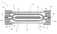
- FIG. 3 is an explanatory sectional view showing an example of the configuration of the third ultraviolet radiation device of the present invention.
- the third ultraviolet radiation device 12 is the same as that of the first ultraviolet ray according to FIG. 1 except that the configuration of the excimer lamp 40 constituting the ultraviolet light source is different and that no reflective member is provided in the outer cover member 50. It has the same configuration as the radiation device 10.
- the outer member 50 has basically the same configuration as the outer member 30 in the first ultraviolet radiation device 10 according to FIG. 1, and specifically, an excimer lamp.
- a cylindrical sheath tube (ozone generating layer forming member) 31 that transmits radiation light (ultraviolet rays) from 40 and base members 52A and 52B disposed at both ends of the sheath tube 31 are provided.
- the excimer lamp 40 is provided with an arc tube 41 having a single tube structure. More specifically, the excimer lamp 40 is made of a dielectric material that transmits ultraviolet rays, such as synthetic quartz glass and fused silica glass, and has flat sealing portions 42A and 42B formed at both ends by a pinch seal method. A long cylindrical arc tube 41 is formed. The arc tube 41 is filled with a discharge gas, and a coiled internal electrode 44 is disposed so as to extend along the tube axis of the arc tube 41.
- the internal electrode 44 is electrically connected to the metal foils 46A and 46B embedded in the sealing portions 42A and 42B through the internal leads 45A and 45B, and the sealing portions 42A are connected to the metal foils 46A and 46B. , 42B, one end portions of the internal electrode external leads 47A, 47B projecting outward from the outer end face are electrically connected.
- a net-like external electrode 48 is provided on the outer peripheral surface of the arc tube 41, and one end of an external electrode external lead 49 extending along the sealing portion 42A is electrically connected to the external electrode 48. ing.
- a discharge region is formed in a region where the internal electrode 44 and the external electrode 48 face each other through the internal space of the arc tube 41 and the tube wall (dielectric material) of the arc tube 41.
- ceramic lamp base members 55A and 55B are mounted on the sealing portions 42A and 42B of the excimer lamp 40, respectively.
- the lamp base members 55A and 55B have a columnar appearance.
- the external lead for external electrodes 49 and the external leads for internal electrodes 47A and 47B are each connected to a high-frequency power source (not shown) via a feeder line (not shown).
- the external electrode 48 is a ground electrode (low voltage side electrode)
- the internal electrode 44 is a high voltage supply electrode.
- the excimer lamp 40 a lamp having a central wavelength in the wavelength range of 190 to 250 nm is used, like the excimer lamp 20 according to the first ultraviolet radiation device 10.
- the excimer lamp used as the excimer lamp 40 and having a center wavelength in the wavelength range of 190 to 250 nm light including ozone-generated ultraviolet rays is emitted.
- the outer member 50 is arranged so that the outer tube 31 surrounds the excimer lamp 40 in a state of being separated from the excimer lamp 40, and an ozone generation layer forming space between the outer tube 31 and the excimer lamp 40.
- an ozone generation layer is formed.
- the base members 52A and 52B each have an inner diameter equivalent to the outer diameter of the lamp base members 55A and 55B, and have an annular cylindrical shape having an outer diameter slightly larger than the outer tube 31. belongs to.
- An annular outer tube support groove 53 is formed on the inner surfaces of the base members 52A and 52B (the surface facing the excimer lamp 40).
- the excimer lamp 40 is supported by the base members 52A and 52B in a state where the lamp base members 55A and 55B are mounted on the sealing portions 42A and 42B.
- the outer tube 31 is supported by the base members 52 ⁇ / b> A and 52 ⁇ / b> B so that the tube axis of the outer tube 31 coincides with the tube axis of the arc tube 41. That is, the outer tube 31 is separated from the outer peripheral surface of the excimer lamp 40 (specifically, the outer peripheral surface of the arc tube 41 provided with the external electrode 48) over the entire inner peripheral surface of the outer tube 31. It is said that.
- the ozone generation layer formation space S2 is a substantially airtight closed space where ozone generated in the ozone generation layer does not leak.
- excimer discharge is generated inside the arc tube 41 by applying a high-frequency high voltage to the internal electrode 44 and the external electrode 48 of the excimer lamp 40 by a high-frequency power source.
- Excimer light corresponding to the type of working gas or the type of ultraviolet light emitting phosphor is emitted from the outer peripheral surface of the arc tube 41 as emitted light.
- the emitted light from the excimer lamp 40 is directly emitted from the outer tube 31.
- an ozone generation layer is formed in the ozone generation layer formation space S ⁇ b> 2 between the excimer lamp 40 and the outer tube 31. For this reason, the ozone-generating ultraviolet rays contained in the radiated light of the excimer lamp 40 are selectively absorbed in the ozone-generating layer. As a result, it is possible to reduce the emission intensity of the ozone-generated ultraviolet light without reducing the emission intensity of ultraviolet light other than the ozone-generated ultraviolet light in the emitted light of the third ultraviolet radiation device 12.
- the ozone generation layer forming space S2 in which the ozone generation layer is formed is a substantially airtight closed space, ozone generated by ozone generation ultraviolet rays being absorbed in the ozone generation gas in the ozone generation layer. However, it does not leak outside the device.
- a discharge may occur between the external electrode 48 and the arc tube 41. When this discharge occurs, ozone is generated due to the discharge. Although it occurs, the ozone does not leak outside the device.
- the ozone generation layer is heated by the heat from the excimer lamp 40 and the temperature is raised, the ozone generated in the ozone generation layer is heated and thus quickly decomposed (thermally decomposed) to generate oxygen. Generated. Therefore, even if the ozone generation layer formation space S2 is a substantially airtight closed space, the ozone generation ultraviolet absorption capacity of the ozone generation layer does not deteriorate with time.
- the third ultraviolet radiation device 12 it is possible to suppress the generation of ozone in the ambient atmosphere outside the device, even when used in an air atmosphere, and in the excimer lamp 40, the discharge gas or By selecting and using an ultraviolet light-emitting phosphor, ultraviolet light having a desired wavelength range around 200 nm can be emitted with high emission intensity. Moreover, even if the third ultraviolet radiation device 12 generates ozone inside the device, the ozone does not leak out of the device.
- FIG. 4 is an explanatory sectional view showing an example of the configuration of the fourth ultraviolet radiation device of the present invention.
- the fourth ultraviolet radiation device 13 is shown in FIG. 1 except that the ultraviolet light source is composed of the LED element 62, the configuration of the outer cover member 65 is different, and no reflective member is provided inside the outer cover member 65.
- the first ultraviolet radiation device 10 has the same configuration.
- the fourth ultraviolet radiation device 13 includes a plurality (9 in the illustrated example) of ultraviolet light sources composed of LED elements 62.
- the plurality of LED elements 62 are constant in the longitudinal direction (left and right direction in FIG. 4) of the LED substrate 61 on the surface (lower surface in FIG. 4) of the long rectangular flat LED substrate 61. They are arranged side by side (for example, at equal intervals).
- the light source unit 60 is constituted by the plurality of LED elements 62 and the LED substrate 61.
- the LED element 62 an appropriate one is used according to the use application of the fourth ultraviolet radiation device 13, specifically according to the wavelength range of ultraviolet rays required in the fourth ultraviolet radiation device 13. It is done. For example, those having a center wavelength in the wavelength range of 190 to 250 nm are used. In the LED element having the center wavelength in the wavelength range of 190 to 250 nm used as the LED element 62, light including ozone-generated ultraviolet rays is emitted.
- all of the plurality of LED elements 62 may be of the same type, or part or all of them may be of different types.
- the outer cover member 65 includes an LED substrate 61, an ozone generation layer forming member (hereinafter also referred to as a “window forming flat plate member”) 66 that transmits ultraviolet rays from the plurality of LED elements 62, and the LED substrate 61.
- the structure is basically the same as that of the mantle member 30 in the first ultraviolet radiation device 10 according to FIG. 1 except that the frame member 67 is disposed along the frame member 67.
- a rectangular tubular mantle tube is constituted by the LED substrate 61, the window forming flat plate member 66, and the side surface portion (not shown) of the frame member 67 extending in the longitudinal direction of the LED substrate 61.
- the outer cover member 65 is disposed along the periphery of the LED substrate 61 so as to surround the LED substrate 61 and the surface of the LED substrate 61 (the surface on which the plurality of LED elements 62 are disposed).
- a rectangular frame member 67 is made of a material having ultraviolet resistance and ozone resistance such as fluorine-based resin, ceramics, and metal, and is configured by four flat plate-like parts perpendicular to the LED substrate 61.
- a fitting groove 68 having a rectangular cross section is formed over the entire circumference of the inner peripheral surface on the front end side (the lower end side in FIG. 4) of the inner peripheral surface of the frame member 67.
- the window forming flat plate member 66 is supported in a state parallel to the LED substrate 61 by a frame member 67.
- the outer cover member 65 is disposed so as to surround the plurality of LED elements 62 in a state in which the window forming flat plate member 66 is separated from the plurality of LED elements 62, and the window forming flat plate member 66 and the light source unit 60 (the plurality of LED elements).
- An ozone generation layer is formed in the ozone generation layer formation space S2 between the element 62).
- the ozone generation layer formation space S2 is a substantially airtight closed space in which ozone generated in the ozone generation layer does not leak.
- ozone decomposition means including a device for thermally decomposing ozone generated in the ozone generation layer, that is, a device for heating the ozone generation layer may be arranged.
- the ozonolysis means include, for example, a heater.
- the plurality of LED elements 62 are turned on all at once, so that the radiation light (ultraviolet rays) from the plurality of LED elements 62 is directly or partially. The other part is reflected by the frame member 67 and then emitted from the window forming flat plate member 66.
- an ozone generation layer is formed in the ozone generation layer formation space S ⁇ b> 2 between the light source unit 60 (the plurality of LED elements 62) and the window forming flat plate member 66. Therefore, the ozone generating ultraviolet rays contained in the radiated light of the light source unit 60 are selectively absorbed in the ozone generating layer. As a result, the emission intensity of the ozone-generated ultraviolet light can be reduced without reducing the emission intensity of ultraviolet light other than the ozone-generated ultraviolet light in the outgoing light of the fourth ultraviolet radiation device 13.
- the ozone generation layer formation space S2 in which the ozone generation layer is formed is a substantially airtight closed space, ozone generated by the ozone generation layer absorbing ozone generation ultraviolet rays in the ozone generation layer. , It will not leak outside the device.
- the ozone generation layer is brought into a high temperature state by heat from the light source unit 60 and heat from a heating means such as a heater provided as necessary, ozone generated in the ozone generation layer Is heated, so that it is quickly decomposed (thermally decomposed) to generate oxygen.
- the ozone generation layer formation space S2 is a substantially airtight closed space, the ozone generation ultraviolet absorption capacity of the ozone generation layer does not deteriorate with time. Therefore, according to the 4th ultraviolet radiation device 13, even if it is a case where it uses in an atmospheric condition, generation
- Such an ultraviolet radiation device of the present invention can be suitably used in a use application where ultraviolet rays having a wavelength range of 190 nm to 250 nm are required in a living space. Specifically, for example, it can be suitably used for skin sterilization treatment using ultraviolet rays having a wavelength of 230 nm or less.
- the ozone generation layer formation space between the ultraviolet light source and the ozone generation layer formation member need not be a closed space, but may be an open space. Even when the ozone generation layer formation space is an open space, the ozone generation layer is heated by heat from an ultraviolet light source, etc., so that the temperature is high, and the ozone generation gas constituting the ozone generation layer flows. Therefore, ozone generated in the ozone generation layer is quickly decomposed (thermally decomposed). Therefore, ozone generated in the ozone generation layer does not leak outside the apparatus.
- the ozone generation layer between the ultraviolet light source and the ozone generation layer forming member may be arranged in the formation space.
- Ozone decomposition means may be arranged in the formation space.
- the ozonolysis means an apparatus for thermally decomposing ozone generated in the ozone generation layer, specifically, for example, a heater or the like can be used.
- the first ultraviolet radiation device has a configuration in which the base member is not provided at both ends of the outer tube, and the outer tube and the arc tube of the excimer lamp are connected by glass processing or an adhesive. May be.
- Example 1 An ultraviolet radiation device having the configuration shown in FIG. 1 (hereinafter also referred to as “ultraviolet radiation device (1)”) was produced.
- the produced ultraviolet radiation device (1) has the following specifications.
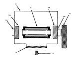
- the measurement mechanism is provided with an ultraviolet irradiation window member 73 on the bottom surface, an air inlet 72A is formed on one of the side surfaces facing each other, and an exhaust port 72B is formed on the other side surface.
- a rectangular box-shaped casing 72 is provided. The intake port 72A and the exhaust port 72B are disposed to face each other.
- an intake fan 74A is disposed so as to close the intake port 72A
- an exhaust fan 74B is disposed so as to close the exhaust port 72B.
- a spectral irradiance meter 75 (“USR-45DA” (USHIO Inc.)) is disposed outside the casing 72 so as to face the ultraviolet irradiation window member 73, and is opposed to the exhaust port 72B.
- an ozone concentration meter 76 (“SM70” (manufactured by Aeroqual) is arranged.
- the object to be measured 79 that is, the ultraviolet radiation device (1) is disposed at a position between the intake fan 74 ⁇ / b> A and the exhaust fan 74 ⁇ / b> B inside the housing 72, and the ultraviolet radiation area of the outer tube is the ultraviolet radiation window member 73. Arranged to face each other.
- Excimer lamp (1) An excimer lamp similar to the excimer lamp (hereinafter also referred to as “excimer lamp (1)”) that constitutes the ultraviolet radiation device (1) according to the first embodiment is manufactured by the same method as in the first embodiment.
- the ultraviolet output (light emission intensity) of the ultraviolet radiation device (1) according to Example 1 is based on the cumulative light emission intensity of ultraviolet rays in the wavelength range of 200 to 230 nm in the excimer lamp (1) according to Comparative Example 1.
- the relative value of the integrated emission intensity in the wavelength range of 200 to 230 nm in the ultraviolet radiation device (1) is shown as 1.
- the ozone concentration of the ultraviolet radiation device (1) is set to 1 based on the ozone concentration in the external environment atmosphere at the time of operation of the excimer lamp (1). The relative value of the ozone concentration is shown.
- the ultraviolet radiation device (1) it is possible to suppress the generation of ozone in the ambient atmosphere outside the device, even when it is used in the atmospheric air, and the wavelength. It was confirmed that ultraviolet rays near 200 nm can be emitted with high emission intensity. More specifically, an ozone generating layer is provided between the outer tube and the excimer lamp (1) by arranging the outer tube (ozone generating layer forming member) so as to surround the excimer lamp (1). According to the ultraviolet radiation device (1) having the configuration, although the radiation intensity of ultraviolet rays in the wavelength range of 200 to 230 nm is reduced by only 5%, the ozone concentration in the atmosphere outside the device is reduced to 1/3 or less. Obviously you can.
Landscapes
- Health & Medical Sciences (AREA)
- Engineering & Computer Science (AREA)
- General Health & Medical Sciences (AREA)
- Biomedical Technology (AREA)
- Life Sciences & Earth Sciences (AREA)
- Physics & Mathematics (AREA)
- Veterinary Medicine (AREA)
- Chemical & Material Sciences (AREA)
- Public Health (AREA)
- Animal Behavior & Ethology (AREA)
- Organic Chemistry (AREA)
- Epidemiology (AREA)
- Chemical Kinetics & Catalysis (AREA)
- Electromagnetism (AREA)
- Toxicology (AREA)
- Plasma & Fusion (AREA)
- Pathology (AREA)
- Nuclear Medicine, Radiotherapy & Molecular Imaging (AREA)
- Radiology & Medical Imaging (AREA)
- Physical Or Chemical Processes And Apparatus (AREA)
- Apparatus For Disinfection Or Sterilisation (AREA)
- Radiation-Therapy Devices (AREA)
- Vessels And Coating Films For Discharge Lamps (AREA)
Abstract
本発明は、大気雰囲気下において用いた場合であっても、装置外部環境雰囲気中におけるオゾンの発生を抑制することができると共に、波長200nm付近の紫外線を高い発光強度で出射することのできる紫外線放射装置を提供することを目的とする。 本発明の紫外線放射装置は、酸素に吸収されてオゾンを発生する波長の紫外線を含む光を放射する紫外線光源、およびこの紫外線光源から離間して配置された、当該紫外線光源との間に紫外線を吸収してオゾンを発生する気体によるオゾン発生層を形成するためのオゾン発生層形成部材を備えており、前記紫外線光源からの光が、前記オゾン発生層形成部材を介して出射されることを特徴とする。
Description
本発明は、紫外線放射装置に関し、更に詳しくは皮膚等の殺菌処理、および脱臭処理などに好適に用いられる紫外線放射装置に関する。
例えば、皮膚等の殺菌処理、脱臭処理、および有機汚染物の除去処理などに紫外線が好適に利用されている。また、紫外線光源としては、エキシマランプが広く知られている(例えば、特許文献1参照。)。
エキシマランプの或る種のものとしては、図6に示すように、円筒状の外側管22と、この外側管22内においてその管軸に沿って配置された、当該外側管22の内径より小さい外径を有する円筒状の内側管23とを有する合成石英ガラス製の二重管構造の発光管21を備えている。この発光管21においては、外側管22および内側管23の各々の両端部が封止壁部材24A,24Bによって接合され、外側管22と内側管23との間に円環状の内部空間S1が形成されている。この内部空間S1には、放電用ガスが封入されている。また、発光管21には、外側管22の外周面に網状の外側電極25が設けられ、内側管23の内周面に膜状の内側電極26が設けられており、外側電極25および内側電極26は、それぞれ高周波電源19に接続されている。
このエキシマランプ20においては、高周波電源19によって外側電極25と内側電極26との間に高周波高電圧が印加されることにより、内部空間S1においてエキシマ放電が発生し、エキシマ光が放射される。
エキシマランプの或る種のものとしては、図6に示すように、円筒状の外側管22と、この外側管22内においてその管軸に沿って配置された、当該外側管22の内径より小さい外径を有する円筒状の内側管23とを有する合成石英ガラス製の二重管構造の発光管21を備えている。この発光管21においては、外側管22および内側管23の各々の両端部が封止壁部材24A,24Bによって接合され、外側管22と内側管23との間に円環状の内部空間S1が形成されている。この内部空間S1には、放電用ガスが封入されている。また、発光管21には、外側管22の外周面に網状の外側電極25が設けられ、内側管23の内周面に膜状の内側電極26が設けられており、外側電極25および内側電極26は、それぞれ高周波電源19に接続されている。
このエキシマランプ20においては、高周波電源19によって外側電極25と内側電極26との間に高周波高電圧が印加されることにより、内部空間S1においてエキシマ放電が発生し、エキシマ光が放射される。
紫外線による殺菌処理(具体的には、皮膚の殺菌処理)においては、波長200nm付近の紫外線、具体的には、概ね波長200~250nmの範囲の紫外線が使用される。
而して、エキシマランプは、放電用ガスの種類によって放射される光の波長特性(波長範囲)を調整できるものであることから、放電用ガスとして適宜のガスを用いることにより、波長200nm付近に中心波長を有する放射光(紫外線)を得ることができる。具体的に、波長200nm付近に中心波長を有する放射光を得るための放電用ガス(以下、「特定放電用ガス」ともいう。)としては、例えば、フッ化アルゴン(ArF)ガス(得られる放射光の中心波長193nm)、臭化クリプトン(KrBr)ガス(得られる放射光の中心波長207nm)、塩化クリプトン(KrCl)ガス(得られる放射光の中心波長222nm)、フッ化クリプトン(KrF)ガス(得られる放射光の中心波長248nm)、ヨウ化キセノン(XeI)ガス(得られる放射光の中心波長253nm)、および塩素(Cl2 )ガス(得られる放射光の中心波長259nm)などが挙げられる。
而して、エキシマランプは、放電用ガスの種類によって放射される光の波長特性(波長範囲)を調整できるものであることから、放電用ガスとして適宜のガスを用いることにより、波長200nm付近に中心波長を有する放射光(紫外線)を得ることができる。具体的に、波長200nm付近に中心波長を有する放射光を得るための放電用ガス(以下、「特定放電用ガス」ともいう。)としては、例えば、フッ化アルゴン(ArF)ガス(得られる放射光の中心波長193nm)、臭化クリプトン(KrBr)ガス(得られる放射光の中心波長207nm)、塩化クリプトン(KrCl)ガス(得られる放射光の中心波長222nm)、フッ化クリプトン(KrF)ガス(得られる放射光の中心波長248nm)、ヨウ化キセノン(XeI)ガス(得られる放射光の中心波長253nm)、および塩素(Cl2 )ガス(得られる放射光の中心波長259nm)などが挙げられる。
エキシマランプの放射光は、実用上単色光とみなすことのできるものであり、そのスペクトル(放射スペクトル)は、線スペクトルであるが、ある程度のスペクトル線幅を有するものである。そのため、エキシマランプの放射光には、中心波長の光と共に、中心波長よりも長波長側の光および中心波長よりも短波長側の光も含まれる。
それ故、特定放電用ガスが封入されたエキシマランプ(以下、「特定エキシマランプ」ともいう。)において、放射光に波長190nm未満の紫外線が含まれている場合には、オゾン(O3 )が発生する。その理由は、波長190nm未満の紫外線が、酸素に吸収されてオゾンを発生する波長の紫外線(以下、「オゾン発生紫外線」ともいう。)だからである。ここに、酸素存在雰囲気下において、オゾン発生紫外線を放射することによれば、オゾンが効率的に生成される。よって、大気雰囲気中において特定エキシマランプを点灯した場合には、大気中の酸素にオゾン発生紫外線が吸収されることによってオゾンが発生することとなる。
而して、高濃度のオゾンは、人体に悪影響を及ぼすものであることから、特に居住空間などにおいて特定エキシマランプを用いる場合、具体的には、例えば皮膚の殺菌処理にエキシマランプを用いる場合には、オゾンの発生を抑制する必要がある。
それ故、特定放電用ガスが封入されたエキシマランプ(以下、「特定エキシマランプ」ともいう。)において、放射光に波長190nm未満の紫外線が含まれている場合には、オゾン(O3 )が発生する。その理由は、波長190nm未満の紫外線が、酸素に吸収されてオゾンを発生する波長の紫外線(以下、「オゾン発生紫外線」ともいう。)だからである。ここに、酸素存在雰囲気下において、オゾン発生紫外線を放射することによれば、オゾンが効率的に生成される。よって、大気雰囲気中において特定エキシマランプを点灯した場合には、大気中の酸素にオゾン発生紫外線が吸収されることによってオゾンが発生することとなる。
而して、高濃度のオゾンは、人体に悪影響を及ぼすものであることから、特に居住空間などにおいて特定エキシマランプを用いる場合、具体的には、例えば皮膚の殺菌処理にエキシマランプを用いる場合には、オゾンの発生を抑制する必要がある。
そこで、本発明の発明者らは、特定エキシマランプの発光管の構成材料として、真空紫外線カット部材として用いられているガラス管やコーティング剤を利用することを検討した。
具体的には、特定エキシマランプの発光管の構成材料として、真空紫外線カット部材として一般的に使用されている、酸化チタン(TiO2 )をドープしたガラス管を用いることを検討した。しかしながら、酸化チタンが、オゾン発生紫外線だけでなく、波長200nmの紫外線も吸収する特性を有するものであることから、発光管の内部空間において発生した波長200nmの紫外線が当該発光管(酸化チタン)によって吸収され、よって、特定エキシマランプの放射光における波長200nmの紫外線の発光強度が著しく低下することが明らかとなった。
また、特定エキシマランプの発光管の構成材料として、真空紫外線カット部材として用いられている各種のガラス管やコーティング剤を使用することも検討したが、波長200nm付近の紫外線の発光強度を大きく低下させることなく、オゾンの発生を抑制することのできる方策を見出すことができなかった。
具体的には、特定エキシマランプの発光管の構成材料として、真空紫外線カット部材として一般的に使用されている、酸化チタン(TiO2 )をドープしたガラス管を用いることを検討した。しかしながら、酸化チタンが、オゾン発生紫外線だけでなく、波長200nmの紫外線も吸収する特性を有するものであることから、発光管の内部空間において発生した波長200nmの紫外線が当該発光管(酸化チタン)によって吸収され、よって、特定エキシマランプの放射光における波長200nmの紫外線の発光強度が著しく低下することが明らかとなった。
また、特定エキシマランプの発光管の構成材料として、真空紫外線カット部材として用いられている各種のガラス管やコーティング剤を使用することも検討したが、波長200nm付近の紫外線の発光強度を大きく低下させることなく、オゾンの発生を抑制することのできる方策を見出すことができなかった。
本発明は、本発明の発明者らが、大気雰囲気下において好適に用いることのできる紫外線放射手段について研究を重ねた結果、見出されたものであって、その目的は、大気雰囲気下において用いた場合であっても、装置外部環境雰囲気中におけるオゾンの発生を抑制することができると共に、波長200nm付近の紫外線を高い発光強度で出射することのできる紫外線放射装置を提供することにある。
本発明の紫外線放射装置は、酸素に吸収されてオゾンを発生する波長の紫外線を含む光を放射する紫外線光源、およびこの紫外線光源から離間して配置された、当該紫外線光源との間に紫外線を吸収してオゾンを発生する気体によるオゾン発生層を形成するためのオゾン発生層形成部材を備えており、
前記紫外線光源からの光が、前記オゾン発生層形成部材を介して出射されることを特徴とする。
前記紫外線光源からの光が、前記オゾン発生層形成部材を介して出射されることを特徴とする。
本発明の紫外線放射装置においては、前記オゾン発生層形成部材が外套管を構成しており、当該外套管が前記紫外線光源を包囲するように配置されていることが好ましい。
本発明の紫外線放射装置においては、前記紫外線光源がエキシマランプよりなることが好ましい。
本発明の紫外線放射装置においては、前記紫外線光源がLED素子よりなることが好ましい。
本発明の紫外線放射装置においては、前記オゾン発生層が空気層よりなり、当該空気層の厚みが20mm以下であることが好ましい。
本発明の紫外線放射装置においては、紫外線を吸収してオゾンを発生する気体によるオゾン発生層が、酸素に吸収されてオゾンを発生する波長の紫外線(オゾン発生紫外線)を含む光を放射する紫外線光源とオゾン発生層形成部材との間に設けられており、当該紫外線光源からの光が、当該オゾン発生層形成部材を介して出射される。そのため、紫外線光源からの光に含まれるオゾン発生紫外線が、オゾン発生層において選択的に吸収される。その結果、本発明の紫外線放射装置からの出射光において、オゾン発生紫外線以外の紫外線の発光強度を大きく低下させることなく、オゾン発生紫外線の発光強度を低下させることができる。
従って、本発明の紫外線放射装置によれば、大気雰囲気下において用いた場合であっても、装置外部環境雰囲気中におけるオゾンの発生を抑制することができると共に、波長200nm付近の紫外線を高い発光強度で放射することができる。
従って、本発明の紫外線放射装置によれば、大気雰囲気下において用いた場合であっても、装置外部環境雰囲気中におけるオゾンの発生を抑制することができると共に、波長200nm付近の紫外線を高い発光強度で放射することができる。
以下、本発明の実施の形態について詳細に説明する。
(第1の紫外線放射装置)
図1は、本発明の第1の紫外線放射装置の構成の一例を示す説明用断面図である。
この第1の紫外線放射装置10は、直管状のエキシマランプ20よりなる紫外線光源と、このエキシマランプ20を囲むように配置された長尺な筒状の外套部材30とを備えている。外套部材30は、エキシマランプ20のランプ中心軸に沿って伸びるように配設されており、当該外套部材30の内部には、エキシマランプ20と共に、当該エキシマランプ20のランプ中心軸に沿って伸びるように反射部材18が配設されている。
この図の例において、反射部材18は、エキシマランプ20の全長よりも長尺な全長を有し、エキシマランプ20の周方向に沿って半円形状に湾曲した矩形曲板状のアルミニウム製の凹平面鏡よりなるものである。そして、反射部材18は、当該反射部材18の反射面(内周面)がエキシマランプ20と対向するように配置されている。ここに、反射部材18は、外套部材30の内周面(具体的には、外套管31の内周面)、または、エキシマランプ20の外周面(具体的には、外側管22の外周面)に設けられたアルミニウムの蒸着膜よりなるものであってもよい。
図1は、本発明の第1の紫外線放射装置の構成の一例を示す説明用断面図である。
この第1の紫外線放射装置10は、直管状のエキシマランプ20よりなる紫外線光源と、このエキシマランプ20を囲むように配置された長尺な筒状の外套部材30とを備えている。外套部材30は、エキシマランプ20のランプ中心軸に沿って伸びるように配設されており、当該外套部材30の内部には、エキシマランプ20と共に、当該エキシマランプ20のランプ中心軸に沿って伸びるように反射部材18が配設されている。
この図の例において、反射部材18は、エキシマランプ20の全長よりも長尺な全長を有し、エキシマランプ20の周方向に沿って半円形状に湾曲した矩形曲板状のアルミニウム製の凹平面鏡よりなるものである。そして、反射部材18は、当該反射部材18の反射面(内周面)がエキシマランプ20と対向するように配置されている。ここに、反射部材18は、外套部材30の内周面(具体的には、外套管31の内周面)、または、エキシマランプ20の外周面(具体的には、外側管22の外周面)に設けられたアルミニウムの蒸着膜よりなるものであってもよい。
エキシマランプ20は、例えば合成石英ガラスおよび溶融石英ガラスなどの紫外線を透過する誘電体材料よりなる発光管21を備えている。発光管21は、円筒状の外側管22と、この外側管22内においてその管軸に沿って配置された、当該外側管22の内径より小さい外径を有する円筒状の内側管23とを有する二重管構造のものである。この発光管21において、外側管22と内側管23とは、外側管22の管軸と内側管23の管軸とが一致するように配置されており、これらの外側管22の管軸および内側管の管軸23が、ランプ中心軸とされている。また、発光管21においては、外側管22および内側管23の各々の両端部が封止壁部材24A,24Bによって接合され、外側管22と内側管23との間に円環状の内部空間S1が形成されている。この内部空間S1には、放電用ガスが封入されている。また、発光管21には、外側管22の外周面に密接して、例えばステンレス鋼などよりなる網状の外側電極25が設けられており、また内側管23の内周面には、当該内周面に密接して、例えばアルミニウムよりなる膜状の内側電極26が設けられている。これらの外側電極25と内側電極26とよりなる一対の電極は、互いに対向するように配置されており、この外側電極25および内側電極26と、内部空間S1との境界には、各々、発光管21の管壁(誘電体材料)が介在した状態とされている。そして、発光管21の内部空間S1においては、一対の電極が、発光管21の管壁(誘電体材料)および内部空間S1を介して対向する領域において、放電領域が形成されている。
この図の例において、外側電極25および内側電極26は、各々、リード線(図示省略)を介して高周波電源(図示省略)に接続されている。また、漏電防止のため、外側電極25を接地電極(低電圧側電極)とし、内側電極26を高電圧供給電極としている。
この図の例において、外側電極25および内側電極26は、各々、リード線(図示省略)を介して高周波電源(図示省略)に接続されている。また、漏電防止のため、外側電極25を接地電極(低電圧側電極)とし、内側電極26を高電圧供給電極としている。
エキシマランプ20としては、波長190~250nmの波長範囲に中心波長を有するものが好適に用いられる。このエキシマランプ20として用いられる、波長190~250nmの波長範囲に中心波長を有するエキシマランプにおいては、オゾン発生紫外線を含む光が放射される。
また、エキシマランプ20としては、波長200~250nmの波長範囲にピーク波長を有する紫外線発光蛍光体を、発光管21の内周面に塗布した構成の紫外線エキシマ蛍光ランプを用いることができる。ここに、紫外線発光蛍光体からの蛍光は、エキシマランプの放射光と同様に、ある程度のスペクトル線幅を有するものであり、よってピーク波長の光と共に、ピーク波長よりも長波長側の光および中心波長よりも短波長側の光も含んでいる。そのため、波長200~250nmの波長範囲にピーク波長を有する紫外線発光蛍光体が塗布されてなる紫外線エキシマ蛍光ランプは、オゾン発生紫外線を含む光を放射するものである。すなわち、紫外線エキシマ蛍光ランプを、大気雰囲気下において点灯した場合には、当該紫外線エキシマ蛍光ランプの放射光に含まれるオゾン発生紫外線が酸素に吸収されることによってオゾン(O3 )が発生することとなる。
エキシマランプ20に用いられる放電用ガスの具体例としては、例えば、フッ化アルゴン(ArF)ガス(得られる放射光の中心波長193nm)、臭化クリプトン(KrBr)ガス(得られる放射光の中心波長207nm)、塩化クリプトン(KrCl)ガス(得られる放射光の中心波長222nm)、フッ化クリプトン(KrF)ガス(得られる放射光の中心波長248nm)、ヨウ化キセノン(XeI)ガス(得られる放射光の中心波長253nm)、および塩素(Cl2 )ガス(得られる放射光の中心波長259nm)などが挙げられる。これらのうちでは、フッ化アルゴンガス、臭化クリプトンガスおよび塩化クリプトンガスが好ましく、更に好ましくは臭化クリプトンガスおよび塩化クリプトンガスであり、特に好ましくは塩化クリプトンガスである。
また、エキシマランプ20としては、波長200~250nmの波長範囲にピーク波長を有する紫外線発光蛍光体を、発光管21の内周面に塗布した構成の紫外線エキシマ蛍光ランプを用いることができる。ここに、紫外線発光蛍光体からの蛍光は、エキシマランプの放射光と同様に、ある程度のスペクトル線幅を有するものであり、よってピーク波長の光と共に、ピーク波長よりも長波長側の光および中心波長よりも短波長側の光も含んでいる。そのため、波長200~250nmの波長範囲にピーク波長を有する紫外線発光蛍光体が塗布されてなる紫外線エキシマ蛍光ランプは、オゾン発生紫外線を含む光を放射するものである。すなわち、紫外線エキシマ蛍光ランプを、大気雰囲気下において点灯した場合には、当該紫外線エキシマ蛍光ランプの放射光に含まれるオゾン発生紫外線が酸素に吸収されることによってオゾン(O3 )が発生することとなる。
エキシマランプ20に用いられる放電用ガスの具体例としては、例えば、フッ化アルゴン(ArF)ガス(得られる放射光の中心波長193nm)、臭化クリプトン(KrBr)ガス(得られる放射光の中心波長207nm)、塩化クリプトン(KrCl)ガス(得られる放射光の中心波長222nm)、フッ化クリプトン(KrF)ガス(得られる放射光の中心波長248nm)、ヨウ化キセノン(XeI)ガス(得られる放射光の中心波長253nm)、および塩素(Cl2 )ガス(得られる放射光の中心波長259nm)などが挙げられる。これらのうちでは、フッ化アルゴンガス、臭化クリプトンガスおよび塩化クリプトンガスが好ましく、更に好ましくは臭化クリプトンガスおよび塩化クリプトンガスであり、特に好ましくは塩化クリプトンガスである。
外套部材30は、エキシマランプ20からの放射光(紫外線)を透過する円筒状のオゾン発生層形成部材(外套管)31と、この外套管31の両端に配設されたベース部材32A,32Bとを備えたものである。外套管31は、エキシマランプ20の外径(具体的には、外側電極25が設けられた外側管22の外径)よりも大きな内径を有しており、放電領域の長さ、すなわちエキシマランプ20における内側電極26が配置されている領域のランプ中心軸方向(図1における左右方向)の長さよりも長尺な全長を有している。
また、ベース部材32A,32Bは、外套管31を支持固定すると共に、エキシマランプ20および反射部材18を支持固定している。
この図の例において、ベース部材32A,32Bは、各々、エキシマランプ20の内側管23の内径よりも僅かに小径の内径を有し、外套管31の外径よりも僅かに大径の外径を有する円環筒状のものである。ベース部材32A,32Bが円環筒状のものであることにより、装置外部環境雰囲気を構成する空気によってエキシマランプ20を冷却することができる。
また、ベース部材32A,32Bの内方面(エキシマランプ20を臨む面)には、円環状の外套管支持用溝33aと、この外套管用支持用溝33aの内方側に設けられた円環状の反射部材支持用溝33bと、この反射部材支持用溝33bの内方側に設けられた円環状のランプ支持用溝33cとが、同心円状に形成されている。
また、内側管21の内周面は、その全面が内側電極26およびベース部材32A,32Bによって覆われている。そのため、内側管23を介して光(紫外線)が放射されることがないことから、内側管23から装置外部に光が照射されることに起因してオゾンが発生することがない。
また、ベース部材32A,32Bは、外套管31を支持固定すると共に、エキシマランプ20および反射部材18を支持固定している。
この図の例において、ベース部材32A,32Bは、各々、エキシマランプ20の内側管23の内径よりも僅かに小径の内径を有し、外套管31の外径よりも僅かに大径の外径を有する円環筒状のものである。ベース部材32A,32Bが円環筒状のものであることにより、装置外部環境雰囲気を構成する空気によってエキシマランプ20を冷却することができる。
また、ベース部材32A,32Bの内方面(エキシマランプ20を臨む面)には、円環状の外套管支持用溝33aと、この外套管用支持用溝33aの内方側に設けられた円環状の反射部材支持用溝33bと、この反射部材支持用溝33bの内方側に設けられた円環状のランプ支持用溝33cとが、同心円状に形成されている。
また、内側管21の内周面は、その全面が内側電極26およびベース部材32A,32Bによって覆われている。そのため、内側管23を介して光(紫外線)が放射されることがないことから、内側管23から装置外部に光が照射されることに起因してオゾンが発生することがない。
この外套部材30は、外套管31が、エキシマランプ20と離間した状態で当該エキシマランプ20を包囲するように配置されている。すなわち、外套部材30の内部において、エキシマランプ20は、外套管31と離間して配置されている。
この図の例において、外套管31は、ベース部材32A,32Bにより、当該外套管31の管軸が、エキシマランプ20のランプ中心軸と一致するように支持されている。すなわち、外套管31は、当該外套管31の内周面の全周にわたって、エキシマランプ20の外周面(具体的には、外側電極25が設けられた外側管22の外周面)と離間した状態とされている。
この図の例において、外套管31は、ベース部材32A,32Bにより、当該外套管31の管軸が、エキシマランプ20のランプ中心軸と一致するように支持されている。すなわち、外套管31は、当該外套管31の内周面の全周にわたって、エキシマランプ20の外周面(具体的には、外側電極25が設けられた外側管22の外周面)と離間した状態とされている。
そして、エキシマランプ20と外套管31との間の空間(以下、「オゾン発生層形成空間」ともいう。)S2には、紫外線を吸収してオゾンを発生する気体(以下、「オゾン生成ガス」ともいう。)が満たされることにより、当該オゾン生成ガスによるオゾン発生層が形成されている。
オゾン生成ガスとしては、酸素を含有するガス、具体的には空気(装置外部環境雰囲気を構成する空気)が挙げられる。
この図の例において、エキシマランプ20と外套管31との間には、円環状のオゾン発生層形成空間S2が形成されており、この円環状のオゾン発生層形成空間S2内に、反射部材18が位置されている。すなわち、反射部材18は、外套部材30の内部において、当該反射部材18の反射面(内周面)が極めて僅かな間隙を介してエキシマランプ20と対向し、当該反射部材18の裏面(外周面)が極めて僅かな間隙を介して外套管31と対向するように配置されている。そして、外套管31における反射部材18と対向していない領域によって紫外線出射領域が形成されている。また、オゾン発生層形成空間S2は、オゾン発生層において発生したオゾンが漏出することのない略気密な閉塞空間とされている。
オゾン生成ガスとしては、酸素を含有するガス、具体的には空気(装置外部環境雰囲気を構成する空気)が挙げられる。
この図の例において、エキシマランプ20と外套管31との間には、円環状のオゾン発生層形成空間S2が形成されており、この円環状のオゾン発生層形成空間S2内に、反射部材18が位置されている。すなわち、反射部材18は、外套部材30の内部において、当該反射部材18の反射面(内周面)が極めて僅かな間隙を介してエキシマランプ20と対向し、当該反射部材18の裏面(外周面)が極めて僅かな間隙を介して外套管31と対向するように配置されている。そして、外套管31における反射部材18と対向していない領域によって紫外線出射領域が形成されている。また、オゾン発生層形成空間S2は、オゾン発生層において発生したオゾンが漏出することのない略気密な閉塞空間とされている。
オゾン発生層の厚み、すなわちエキシマランプ20と外套管31との離間距離は、オゾン生成ガスの種類に応じ、エキシマランプ20の構成(具体的に、放電用ガスの種類等)およびエキシマランプ20の点灯条件などを考慮して適宜に定められる。
具体的には、オゾン生成ガスが空気である場合、すなわちオゾン発生層が空気層よりなる場合においては、オゾン発生層の厚みは、0.1~20mmであることが好ましく、更に好ましくは1~2mmである。
オゾン発生層の厚みが過小である場合には、当該オゾン発生層のオゾン発生紫外線吸収能が小さくなり、当該オゾン発生層におけるオゾンの発生量、すなわちオゾン発生層において吸収されるオゾン発生紫外線の量が小さくなる。そのため、装置外部環境雰囲気中におけるオゾンの発生を十分に抑制することができなくなるおそれがある。
一方、オゾン発生層の厚みが過大である場合には、オゾン発生層による保温作用が大きくなる。そのため、エキシマランプ20が点灯されることによって生じる熱などにより当該エキシマランプ20が過度に加熱されることに起因して、エキシマランプ20の使用寿命が短くなるおそれがある。
具体的には、オゾン生成ガスが空気である場合、すなわちオゾン発生層が空気層よりなる場合においては、オゾン発生層の厚みは、0.1~20mmであることが好ましく、更に好ましくは1~2mmである。
オゾン発生層の厚みが過小である場合には、当該オゾン発生層のオゾン発生紫外線吸収能が小さくなり、当該オゾン発生層におけるオゾンの発生量、すなわちオゾン発生層において吸収されるオゾン発生紫外線の量が小さくなる。そのため、装置外部環境雰囲気中におけるオゾンの発生を十分に抑制することができなくなるおそれがある。
一方、オゾン発生層の厚みが過大である場合には、オゾン発生層による保温作用が大きくなる。そのため、エキシマランプ20が点灯されることによって生じる熱などにより当該エキシマランプ20が過度に加熱されることに起因して、エキシマランプ20の使用寿命が短くなるおそれがある。
この第1の紫外線放射装置10においては、エキシマランプ20の一対の電極に対して高周波電源によって高周波高電圧を印加することにより、内部空間S1においてエキシマ放電が発生し、放電用ガスの種類または紫外線発光蛍光体の種類に応じたエキシマ光が放射光として、直接的に、または内側電極26によって反射された後、外側管22の外周面から放射される。そして、エキシマランプ20の放射光は、その一部が直接的に、また他の一部が反射部材18によって反射された後、外套管31の紫外線出射領域から出射される。
而して、第1の紫外線放射装置10においては、エキシマランプ20と外套管31との間のオゾン発生層形成空間S2にオゾン発生層が形成されている。そのため、エキシマランプ20の放射光に含まれるオゾン発生紫外線が、オゾン発生層において選択的に吸収される。その結果、第1の紫外線放射装置10の出射光において、オゾン発生紫外線以外の紫外線の発光強度を低下させることなく、オゾン発生紫外線の発光強度を低下させることができる。
また、オゾン発生層が形成されるオゾン発生層形成空間S2が略気密な閉塞空間とされていることから、オゾン発生層において、オゾン発生紫外線がオゾン生成ガスに吸収されることによって発生したオゾンが、装置外部に漏洩することがない。しかも、オゾン発生層形成空間S2においては、外側電極25と外側管22との間において放電(沿面放電)が生じることがあり、その放電が生じた場合には、当該放電に起因してオゾンが発生するが、そのオゾンが装置外部に漏洩することもない。
また、オゾン発生層がエキシマランプ20からの熱などによって加熱されて温度が高い状態とされることから、オゾン発生層において発生したオゾンが加熱され、よって速やかに分解(熱分解)されて酸素が生成される。そのため、オゾン発生層形成空間S2が略気密な閉塞空間とされていても、オゾン発生層のオゾン発生紫外線吸収能が経時的に低下することがない。
従って、第1の紫外線放射装置10によれば、大気雰囲気下において用いた場合であっても、装置外部環境雰囲気中におけるオゾンの発生を抑制することができると共に、エキシマランプ20において放電用ガスまたは紫外線発光蛍光体を選択して用いることによって波長200nm付近の所望の波長範囲の紫外線を高い発光強度で放射することができる。しかも、第1の紫外線放射装置10が、装置内部においてオゾンが発生するものであっても、そのオゾンが装置外部に漏出することがない。
また、オゾン発生層が形成されるオゾン発生層形成空間S2が略気密な閉塞空間とされていることから、オゾン発生層において、オゾン発生紫外線がオゾン生成ガスに吸収されることによって発生したオゾンが、装置外部に漏洩することがない。しかも、オゾン発生層形成空間S2においては、外側電極25と外側管22との間において放電(沿面放電)が生じることがあり、その放電が生じた場合には、当該放電に起因してオゾンが発生するが、そのオゾンが装置外部に漏洩することもない。
また、オゾン発生層がエキシマランプ20からの熱などによって加熱されて温度が高い状態とされることから、オゾン発生層において発生したオゾンが加熱され、よって速やかに分解(熱分解)されて酸素が生成される。そのため、オゾン発生層形成空間S2が略気密な閉塞空間とされていても、オゾン発生層のオゾン発生紫外線吸収能が経時的に低下することがない。
従って、第1の紫外線放射装置10によれば、大気雰囲気下において用いた場合であっても、装置外部環境雰囲気中におけるオゾンの発生を抑制することができると共に、エキシマランプ20において放電用ガスまたは紫外線発光蛍光体を選択して用いることによって波長200nm付近の所望の波長範囲の紫外線を高い発光強度で放射することができる。しかも、第1の紫外線放射装置10が、装置内部においてオゾンが発生するものであっても、そのオゾンが装置外部に漏出することがない。
(第2の紫外線放射装置)
図2は、本発明の第2の紫外線放射装置の構成の一例を示す説明用断面図である。
この第2の紫外線放射装置11は、外套部材35の構成が異なること、および外套部材35の内部に反射部材が設けられていないこと以外は、図1に係る第1の紫外線放射装置10と同様の構成を有するものである。また、第2の紫外線放射装置11において、エキシマランプ20は、図1に係る第1の紫外線放射装置10におけるエキシマランプ20と同様の構成のものである。
図2は、本発明の第2の紫外線放射装置の構成の一例を示す説明用断面図である。
この第2の紫外線放射装置11は、外套部材35の構成が異なること、および外套部材35の内部に反射部材が設けられていないこと以外は、図1に係る第1の紫外線放射装置10と同様の構成を有するものである。また、第2の紫外線放射装置11において、エキシマランプ20は、図1に係る第1の紫外線放射装置10におけるエキシマランプ20と同様の構成のものである。
第2の紫外線放射装置11において、外套部材35は、外套管36が、エキシマランプ20からの放射光(紫外線)を透過するオゾン発生層形成部材(以下、「窓形成湾曲板部材」ともいう。)37と、エキシマランプ20からの放射光(紫外線)を反射する反射面を有する反射ブロック部材38とにより構成されていること以外は、図1に係る第1の紫外線放射装置10における外套部材30と基本的に同様の構成のものである。
具体的に説明すると、外套部材35は、エキシマランプ20の周方向に沿って半円形状に湾曲した矩形曲板状の窓形成湾曲板部材37と、窓形成湾曲板部材37の全長と同等の全長を有し、エキシマランプ20の周方向に沿うように屈曲した略V字状の反射ブロック部材38とよりなる外套管36を備えている。この外套管36は、反射ブロック部材38の接続面に形成された嵌合溝38aに、窓形成湾曲板部材37の嵌合縁部37aが嵌合されたものである。また、外套管36は、エキシマランプ20の外径(具体的には、外側電極25が設けられた外側管22の外径)よりも大きな内径を有しており、放電領域の長さ、すなわちエキシマランプ20における内側電極26が配置されている領域のランプ中心軸方向(図2における紙面に垂直な方向)の長さよりも長尺な全長を有している。そして、外套管36の両端には、ベース部材(図示省略)が配設されている。このベース部材は、外套管36を支持固定すると共に、エキシマランプ20を支持固定している。
具体的に説明すると、外套部材35は、エキシマランプ20の周方向に沿って半円形状に湾曲した矩形曲板状の窓形成湾曲板部材37と、窓形成湾曲板部材37の全長と同等の全長を有し、エキシマランプ20の周方向に沿うように屈曲した略V字状の反射ブロック部材38とよりなる外套管36を備えている。この外套管36は、反射ブロック部材38の接続面に形成された嵌合溝38aに、窓形成湾曲板部材37の嵌合縁部37aが嵌合されたものである。また、外套管36は、エキシマランプ20の外径(具体的には、外側電極25が設けられた外側管22の外径)よりも大きな内径を有しており、放電領域の長さ、すなわちエキシマランプ20における内側電極26が配置されている領域のランプ中心軸方向(図2における紙面に垂直な方向)の長さよりも長尺な全長を有している。そして、外套管36の両端には、ベース部材(図示省略)が配設されている。このベース部材は、外套管36を支持固定すると共に、エキシマランプ20を支持固定している。
この外套部材35は、外套管36が、エキシマランプ20と離間した状態で当該エキシマランプ20を包囲するように配置されており、外套管36とエキシマランプ20との間のオゾン発生層形成空間S2には、オゾン発生層が形成されている。
この図の例において、外套管36は、ベース部材により、当該外套管36の管軸が、エキシマランプ20のランプ中心軸と一致するように支持されている。すなわち、外套管36は、当該外套管36の内周面の全周にわたって、エキシマランプ20の外周面(具体的には、外側電極25が設けられた外側管22の外周面)と離間した状態とされている。
また、オゾン発生層形成空間S2は、オゾン発生層において発生したオゾンが漏出することのない略気密な閉塞空間とされている。
この図の例において、外套管36は、ベース部材により、当該外套管36の管軸が、エキシマランプ20のランプ中心軸と一致するように支持されている。すなわち、外套管36は、当該外套管36の内周面の全周にわたって、エキシマランプ20の外周面(具体的には、外側電極25が設けられた外側管22の外周面)と離間した状態とされている。
また、オゾン発生層形成空間S2は、オゾン発生層において発生したオゾンが漏出することのない略気密な閉塞空間とされている。
この第2の紫外線放射装置11においては、エキシマランプ20の一対の電極に対して高周波電源によって高周波高電圧を印加することにより、内部空間S1においてエキシマ放電が発生し、放電用ガスの種類または紫外線発光蛍光体の種類に応じたエキシマ光が放射光として、直接的に、または内側電極26によって反射された後、外側管22の外周面から放射される。そして、エキシマランプ20からの放射光は、その一部が直接的に、また他の一部が反射ブロック部材38によって反射された後、窓形成湾曲板部材37から出射される。
而して、第2の紫外線放射装置11においては、エキシマランプ20と外套管36との間のオゾン発生層形成空間S2にオゾン発生層が形成されている。そのため、エキシマランプ20の放射光に含まれるオゾン発生紫外線が、オゾン発生層において選択的に吸収される。その結果、第2の紫外線放射装置11の出射光において、オゾン発生紫外線以外の紫外線の発光強度を低下させることなく、オゾン発生紫外線の発光強度を低下させることができる。
また、オゾン発生層が形成されるオゾン発生層形成空間S2が略気密な閉塞空間とされていることから、オゾン発生層において、オゾン発生紫外線がオゾン生成ガスに吸収されることによって発生したオゾンが、装置外部に漏洩することがない。しかも、オゾン発生層形成空間S2においては、外側電極25と外側管22との間において放電(沿面放電)が生じることがあり、その放電が生じた場合には、当該放電に起因してオゾンが発生するが、そのオゾンが装置外部に漏洩することもない。
また、オゾン発生層がエキシマランプ20からの熱などによって加熱されて温度が高い状態とされることから、オゾン発生層において発生したオゾンが加熱され、よって速やかに分解(熱分解)されて酸素が生成される。そのため、オゾン発生層形成空間S2が略気密な閉塞空間とされていても、オゾン発生層のオゾン発生紫外線吸収能が経時的に低下することがない。
従って、第2の紫外線放射装置11によれば、大気雰囲気下において用いた場合であっても、装置外部環境雰囲気中におけるオゾンの発生を抑制することができると共に、エキシマランプ20において放電用ガスまたは紫外線発光蛍光体を選択して用いることによって波長200nm付近の所望の波長範囲の紫外線を高い発光強度で放射することができる。しかも、第2の紫外線放射装置11が、装置内部においてオゾンが発生するものであっても、そのオゾンが装置外部に漏出することがない。
また、オゾン発生層が形成されるオゾン発生層形成空間S2が略気密な閉塞空間とされていることから、オゾン発生層において、オゾン発生紫外線がオゾン生成ガスに吸収されることによって発生したオゾンが、装置外部に漏洩することがない。しかも、オゾン発生層形成空間S2においては、外側電極25と外側管22との間において放電(沿面放電)が生じることがあり、その放電が生じた場合には、当該放電に起因してオゾンが発生するが、そのオゾンが装置外部に漏洩することもない。
また、オゾン発生層がエキシマランプ20からの熱などによって加熱されて温度が高い状態とされることから、オゾン発生層において発生したオゾンが加熱され、よって速やかに分解(熱分解)されて酸素が生成される。そのため、オゾン発生層形成空間S2が略気密な閉塞空間とされていても、オゾン発生層のオゾン発生紫外線吸収能が経時的に低下することがない。
従って、第2の紫外線放射装置11によれば、大気雰囲気下において用いた場合であっても、装置外部環境雰囲気中におけるオゾンの発生を抑制することができると共に、エキシマランプ20において放電用ガスまたは紫外線発光蛍光体を選択して用いることによって波長200nm付近の所望の波長範囲の紫外線を高い発光強度で放射することができる。しかも、第2の紫外線放射装置11が、装置内部においてオゾンが発生するものであっても、そのオゾンが装置外部に漏出することがない。
(第3の紫外線放射装置)
図3は、本発明の第3の紫外線放射装置の構成の一例を示す説明用断面図である。
この第3の紫外線放射装置12は、紫外線光源を構成するエキシマランプ40の構成が異なること、および外套部材50の内部に反射部材が設けられていないこと以外は、図1に係る第1の紫外線放射装置10と同様の構成を有するものである。また、第3の紫外線放射装置12において、外套部材50は、図1に係る第1の紫外線放射装置10における外套部材30と基本的に同様の構成のものであり、具体的には、エキシマランプ40からの放射光(紫外線)を透過する円筒状の外套管(オゾン発生層形成部材)31と、この外套管31の両端に配設されたベース部材52A,52Bとを備えたものである。
図3は、本発明の第3の紫外線放射装置の構成の一例を示す説明用断面図である。
この第3の紫外線放射装置12は、紫外線光源を構成するエキシマランプ40の構成が異なること、および外套部材50の内部に反射部材が設けられていないこと以外は、図1に係る第1の紫外線放射装置10と同様の構成を有するものである。また、第3の紫外線放射装置12において、外套部材50は、図1に係る第1の紫外線放射装置10における外套部材30と基本的に同様の構成のものであり、具体的には、エキシマランプ40からの放射光(紫外線)を透過する円筒状の外套管(オゾン発生層形成部材)31と、この外套管31の両端に配設されたベース部材52A,52Bとを備えたものである。
第3の紫外線放射装置12において、エキシマランプ40は、一重管構造の発光管41を備えたものである。
具体的に説明すると、エキシマランプ40は、例えば合成石英ガラスおよび溶融石英ガラスなどの紫外線を透過する誘電体材料によって構成され、両端にピンチシール法によって形成された扁平状の封止部42A,42Bが形成された長尺な円筒状の発光管41を備えている。この発光管41の内部には、放電用ガスが封入されていると共に、コイル状の内部電極44が、発光管41の管軸に沿って伸びるように配設されている。この内部電極44は、内部リード45A,45Bを介して封止部42A,42Bに埋設された金属箔46A,46Bに電気的に接続されており、金属箔46A,46Bには、封止部42A,42Bの外端面から外方に突出する内部電極用外部リード47A,47Bの一端部が電気的に接続されている。また、発光管41の外周面には、網状の外部電極48が設けられおり、外部電極48には、封止部42Aに沿って伸びる外部電極用外部リード49の一端部が電気的に接続されている。そして、内部電極44と外部電極48とが、発光管41の内部空間および発光管41の管壁(誘電体材料)を介して対向する領域において、放電領域が形成されている。
また、エキシマランプ40の封止部42A,42Bには、各々、セラミック製のランプベース部材55A,55Bが装着されている。このランプベース部材55A,55Bは、円柱状の外観形状を有するものである。
この図の例において、外部電極用外部リード49および内部電極用外部リード47A,47Bは、各々、給電線(図示省略)を介して高周波電源(図示省略)に接続されている。また、漏電防止のため、外部電極48を接地電極(低電圧側電極)とし、内部電極44を高電圧供給電極としている。
具体的に説明すると、エキシマランプ40は、例えば合成石英ガラスおよび溶融石英ガラスなどの紫外線を透過する誘電体材料によって構成され、両端にピンチシール法によって形成された扁平状の封止部42A,42Bが形成された長尺な円筒状の発光管41を備えている。この発光管41の内部には、放電用ガスが封入されていると共に、コイル状の内部電極44が、発光管41の管軸に沿って伸びるように配設されている。この内部電極44は、内部リード45A,45Bを介して封止部42A,42Bに埋設された金属箔46A,46Bに電気的に接続されており、金属箔46A,46Bには、封止部42A,42Bの外端面から外方に突出する内部電極用外部リード47A,47Bの一端部が電気的に接続されている。また、発光管41の外周面には、網状の外部電極48が設けられおり、外部電極48には、封止部42Aに沿って伸びる外部電極用外部リード49の一端部が電気的に接続されている。そして、内部電極44と外部電極48とが、発光管41の内部空間および発光管41の管壁(誘電体材料)を介して対向する領域において、放電領域が形成されている。
また、エキシマランプ40の封止部42A,42Bには、各々、セラミック製のランプベース部材55A,55Bが装着されている。このランプベース部材55A,55Bは、円柱状の外観形状を有するものである。
この図の例において、外部電極用外部リード49および内部電極用外部リード47A,47Bは、各々、給電線(図示省略)を介して高周波電源(図示省略)に接続されている。また、漏電防止のため、外部電極48を接地電極(低電圧側電極)とし、内部電極44を高電圧供給電極としている。
エキシマランプ40としては、第1の紫外線放射装置10に係るエキシマランプ20と同様に、波長190~250nmの波長範囲に中心波長を有するものが用いられる。このエキシマランプ40として用いられる、波長190~250nmの波長範囲に中心波長を有するエキシマランプにおいては、オゾン発生紫外線を含む光が放射される。
また、外套部材50は、外套管31が、エキシマランプ40と離間した状態で当該エキシマランプ40を包囲するように配置されており、外套管31とエキシマランプ40との間のオゾン発生層形成空間S2には、オゾン発生層が形成されている。
この図の例において、ベース部材52A,52Bは、各々、ランプベース部材55A,55Bの外径と同等の内径を有し、外套管31よりも僅かに大径の外径を有する円環筒状のものである。また、ベース部材52A,52Bの内方面(エキシマランプ40を臨む面)には、円環状の外套管支持用溝53が形成されている。そして、エキシマランプ40は、ベース部材52A,52Bにより、封止部42A,42Bにランプベース部材55A,55Bが装着された状態で支持されている。一方、外套管31は、ベース部材52A,52Bにより、当該外套管31の管軸が、発光管41の管軸と一致するように支持されている。すなわち、外套管31は、当該外套管31の内周面の全周にわたって、エキシマランプ40の外周面(具体的には、外部電極48が設けられた発光管41の外周面)と離間した状態とされている。
また、オゾン発生層形成空間S2は、オゾン発生層において発生したオゾンが漏出することのない略気密な閉塞空間とされている。
この図の例において、ベース部材52A,52Bは、各々、ランプベース部材55A,55Bの外径と同等の内径を有し、外套管31よりも僅かに大径の外径を有する円環筒状のものである。また、ベース部材52A,52Bの内方面(エキシマランプ40を臨む面)には、円環状の外套管支持用溝53が形成されている。そして、エキシマランプ40は、ベース部材52A,52Bにより、封止部42A,42Bにランプベース部材55A,55Bが装着された状態で支持されている。一方、外套管31は、ベース部材52A,52Bにより、当該外套管31の管軸が、発光管41の管軸と一致するように支持されている。すなわち、外套管31は、当該外套管31の内周面の全周にわたって、エキシマランプ40の外周面(具体的には、外部電極48が設けられた発光管41の外周面)と離間した状態とされている。
また、オゾン発生層形成空間S2は、オゾン発生層において発生したオゾンが漏出することのない略気密な閉塞空間とされている。
この第3の紫外線放射装置12においては、エキシマランプ40の内部電極44および外部電極48に対して高周波電源によって高周波高電圧を印加することにより、発光管41の内部においてエキシマ放電が発生し、放電用ガスの種類または紫外線発光蛍光体の種類に応じたエキシマ光が放射光として、当該発光管41の外周面から放射される。そして、エキシマランプ40からの放射光は、直接的に外套管31から出射される。
而して、第3の紫外線放射装置12おいては、エキシマランプ40と外套管31との間のオゾン発生層形成空間S2にオゾン発生層が形成されている。そのため、エキシマランプ40の放射光に含まれるオゾン発生紫外線が、オゾン発生層において選択的に吸収される。その結果、第3の紫外線放射装置12の出射光において、オゾン発生紫外線以外の紫外線の発光強度を低下させることなく、オゾン発生紫外線の発光強度を低下させることができる。
また、オゾン発生層が形成されるオゾン発生層形成空間S2が略気密な閉塞空間とされていることから、このオゾン発生層において、オゾン発生紫外線がオゾン生成ガスに吸収されることによって発生したオゾンが、装置外部に漏洩することがない。しかも、オゾン発生層形成空間S2においては、外部電極48と発光管41との間において放電(沿面放電)が生じることがあり、その放電が生じた場合には、当該放電に起因してオゾンが発生するが、そのオゾンが装置外部に漏洩することもない。
また、オゾン発生層がエキシマランプ40からの熱などによって加熱されて温度が高い状態とされることから、オゾン発生層において発生したオゾンが加熱され、よって速やかに分解(熱分解)されて酸素が生成される。そのため、オゾン発生層形成空間S2が略気密な閉塞空間とされていても、オゾン発生層のオゾン発生紫外線吸収能が経時的に低下することがない。
従って、第3の紫外線放射装置12によれば、大気雰囲気下において用いた場合であっても、装置外部環境雰囲気中におけるオゾンの発生を抑制することができると共に、エキシマランプ40において放電用ガスまたは紫外線発光蛍光体を選択して用いることによって波長200nm付近の所望の波長範囲の紫外線を高い発光強度で放射することができる。しかも、第3の紫外線放射装置12が、装置内部においてオゾンが発生するものであっても、そのオゾンが装置外部に漏出することがない。
また、オゾン発生層が形成されるオゾン発生層形成空間S2が略気密な閉塞空間とされていることから、このオゾン発生層において、オゾン発生紫外線がオゾン生成ガスに吸収されることによって発生したオゾンが、装置外部に漏洩することがない。しかも、オゾン発生層形成空間S2においては、外部電極48と発光管41との間において放電(沿面放電)が生じることがあり、その放電が生じた場合には、当該放電に起因してオゾンが発生するが、そのオゾンが装置外部に漏洩することもない。
また、オゾン発生層がエキシマランプ40からの熱などによって加熱されて温度が高い状態とされることから、オゾン発生層において発生したオゾンが加熱され、よって速やかに分解(熱分解)されて酸素が生成される。そのため、オゾン発生層形成空間S2が略気密な閉塞空間とされていても、オゾン発生層のオゾン発生紫外線吸収能が経時的に低下することがない。
従って、第3の紫外線放射装置12によれば、大気雰囲気下において用いた場合であっても、装置外部環境雰囲気中におけるオゾンの発生を抑制することができると共に、エキシマランプ40において放電用ガスまたは紫外線発光蛍光体を選択して用いることによって波長200nm付近の所望の波長範囲の紫外線を高い発光強度で放射することができる。しかも、第3の紫外線放射装置12が、装置内部においてオゾンが発生するものであっても、そのオゾンが装置外部に漏出することがない。
(第4の紫外線放射装置)
図4は、本発明の第4の紫外線放射装置の構成の一例を示す説明用断面図である。
この第4の紫外線放射装置13は、紫外線光源がLED素子62よりなること、外套部材65の構成が異なること、および外套部材65の内部に反射部材が設けられていないこと以外は、図1に係る第1の紫外線放射装置10と同様の構成を有するものである。
図4は、本発明の第4の紫外線放射装置の構成の一例を示す説明用断面図である。
この第4の紫外線放射装置13は、紫外線光源がLED素子62よりなること、外套部材65の構成が異なること、および外套部材65の内部に反射部材が設けられていないこと以外は、図1に係る第1の紫外線放射装置10と同様の構成を有するものである。
第4の紫外線放射装置13は、LED素子62よりなる複数(図の例においては、9個)の紫外線光源を備えたものである。
この図の例において、複数のLED素子62は、長尺な矩形平板状のLED基板61の表面(図4における下面)に、当該LED基板61の長手方向(図4における左右方向)に一定の間隔(例えば等間隔)で並設されている。そして、複数のLED素子62とLED基板61とによって光源ユニット60が構成されている。
この図の例において、複数のLED素子62は、長尺な矩形平板状のLED基板61の表面(図4における下面)に、当該LED基板61の長手方向(図4における左右方向)に一定の間隔(例えば等間隔)で並設されている。そして、複数のLED素子62とLED基板61とによって光源ユニット60が構成されている。
LED素子62としては、第4の紫外線放射装置13の利用用途などに応じて、具体的には第4の紫外線放射装置13において必要とされる紫外線の波長範囲に応じて、適宜のものが用いられる。例えば、波長190~250nmの波長範囲に中心波長を有するものが用いられる。このLED素子62として用いられる、波長190~250nmの波長範囲に中心波長を有するLED素子においては、オゾン発生紫外線を含む光が放射される。
ここに、複数のLED素子62は、そのすべてが同一種類のものであってもよく、また一部または全部が異なる種類のものであってもよい。
ここに、複数のLED素子62は、そのすべてが同一種類のものであってもよく、また一部または全部が異なる種類のものであってもよい。
また、外套部材65は、LED基板61と、複数のLED素子62からの紫外線を透過するオゾン発生層形成部材(以下、「窓形成平板部材」ともいう。)66と、LED基板61の周縁に沿って配設された枠部材67とにより構成されていること以外は、図1に係る第1の紫外線放射装置10における外套部材30と基本的に同様の構成のものである。この外套部材65においては、LED基板61と窓形成平板部材66と枠部材67におけるLED基板61の長手方向に伸びる側面部(図示省略)とにより、矩形筒状の外套管が構成されている。
具体的に説明すると、外套部材65は、LED基板61と、LED基板61の表面(複数のLED素子62が配置されている面)を囲むよう、当該LED基板61の周縁に沿って配置された矩形状の枠部材67とを備えている。枠部材67は、フッ素系樹脂、セラミックス、および金属などの耐紫外線性および耐オゾン性を有する材料よりなるものであり、LED基板61に垂直な4つの平板状部によって構成されている。そして、枠部材67の内周面における先端側(図4における下端側)には、当該内周面の全周にわたって断面矩形状の嵌合溝68が形成されており、この嵌合溝68には、LED基板61の縦横寸法よりも大きな縦横寸法を有する矩形平板状の窓形成平板部材66の嵌合縁部66aが嵌合されている。このようにして、複数のLED素子62は、外套部材65の内部に配置されている。
この図の例において、窓形成平板部材66は、枠部材67により、LED基板61に平行な状態に支持されている。
具体的に説明すると、外套部材65は、LED基板61と、LED基板61の表面(複数のLED素子62が配置されている面)を囲むよう、当該LED基板61の周縁に沿って配置された矩形状の枠部材67とを備えている。枠部材67は、フッ素系樹脂、セラミックス、および金属などの耐紫外線性および耐オゾン性を有する材料よりなるものであり、LED基板61に垂直な4つの平板状部によって構成されている。そして、枠部材67の内周面における先端側(図4における下端側)には、当該内周面の全周にわたって断面矩形状の嵌合溝68が形成されており、この嵌合溝68には、LED基板61の縦横寸法よりも大きな縦横寸法を有する矩形平板状の窓形成平板部材66の嵌合縁部66aが嵌合されている。このようにして、複数のLED素子62は、外套部材65の内部に配置されている。
この図の例において、窓形成平板部材66は、枠部材67により、LED基板61に平行な状態に支持されている。
この外套部材65は、窓形成平板部材66が複数のLED素子62と離間した状態で複数のLED素子62を包囲するように配置されており、窓形成平板部材66と光源ユニット60(複数のLED素子62)との間のオゾン発生層形成空間S2には、オゾン発生層が形成されている。
この図の例において、オゾン発生層形成空間S2は、オゾン発生層において発生したオゾンが漏出することのない略気密な閉塞空間とされている。
この図の例において、オゾン発生層形成空間S2は、オゾン発生層において発生したオゾンが漏出することのない略気密な閉塞空間とされている。
このオゾン発生層形成空間S2には、オゾン発生層において発生したオゾンを熱分解するための装置、すなわちオゾン発生層を加熱するための装置などよりなるオゾン分解手段が配置されていてもよい。オゾン分解手段の具体例としては、例えばヒータなどが挙げられる。
オゾン発生層形成空間S2にオゾン分解手段が配置されていることにより、光源ユニット60からの熱量が、オゾン発生層を温度が高い状態とすること、具体的にはオゾン分解温度にまで昇温させることが不十分な熱量である場合でも、オゾン発生層を温度が高い状態とすることができる。そのため、オゾン発生層において発生したオゾンが分解(熱分解)される。
オゾン発生層形成空間S2にオゾン分解手段が配置されていることにより、光源ユニット60からの熱量が、オゾン発生層を温度が高い状態とすること、具体的にはオゾン分解温度にまで昇温させることが不十分な熱量である場合でも、オゾン発生層を温度が高い状態とすることができる。そのため、オゾン発生層において発生したオゾンが分解(熱分解)される。
この第4の紫外線放射装置13においては、複数のLED素子62が一斉に点灯されることにより、これらの複数のLED素子62からの放射光(紫外線)が、その一部が直接的に、また他の一部が枠部材67によって反射された後、窓形成平板部材66から出射される。
而して、第4の紫外線放射装置13においては、光源ユニット60(複数のLED素子62)と窓形成平板部材66との間のオゾン発生層形成空間S2にオゾン発生層が形成されている。そのため、光源ユニット60の放射光に含まれるオゾン発生紫外線が、オゾン発生層において選択的に吸収される。その結果、第4の紫外線放射装置13の出射光において、オゾン発生紫外線以外の紫外線の発光強度を低下させることなく、オゾン発生紫外線の発光強度を低下させることができる。
また、オゾン発生層が形成されるオゾン発生層形成空間S2が略気密な閉塞空間とされていることから、オゾン発生層において、オゾン発生紫外線がオゾン生成ガスに吸収されることによって発生したオゾンが、装置外部に漏洩することがない。
また、オゾン発生層が、光源ユニット60からの熱、および必要に応じて配設されるヒータなどの加熱手段からの熱により、温度が高い状態とされることから、オゾン発生層において発生したオゾンが加熱され、よって速やかに分解(熱分解)されて酸素が生成される。そのため、オゾン発生層形成空間S2が略気密な閉塞空間とされていても、オゾン発生層のオゾン発生紫外線吸収能が経時的に低下することがない。
従って、第4の紫外線放射装置13によれば、大気雰囲気下において用いた場合であっても、装置外部環境雰囲気中におけるオゾンの発生を抑制することができると共に、用いる複数のLED素子62の種類を選択することによって波長200nm付近の所望の波長範囲の紫外線を高い発光強度で放射することができる。しかも、第4の紫外線放射装置13が、装置内部においてオゾンが発生するものであっても、そのオゾンが装置外部に漏出することがない。
また、オゾン発生層が形成されるオゾン発生層形成空間S2が略気密な閉塞空間とされていることから、オゾン発生層において、オゾン発生紫外線がオゾン生成ガスに吸収されることによって発生したオゾンが、装置外部に漏洩することがない。
また、オゾン発生層が、光源ユニット60からの熱、および必要に応じて配設されるヒータなどの加熱手段からの熱により、温度が高い状態とされることから、オゾン発生層において発生したオゾンが加熱され、よって速やかに分解(熱分解)されて酸素が生成される。そのため、オゾン発生層形成空間S2が略気密な閉塞空間とされていても、オゾン発生層のオゾン発生紫外線吸収能が経時的に低下することがない。
従って、第4の紫外線放射装置13によれば、大気雰囲気下において用いた場合であっても、装置外部環境雰囲気中におけるオゾンの発生を抑制することができると共に、用いる複数のLED素子62の種類を選択することによって波長200nm付近の所望の波長範囲の紫外線を高い発光強度で放射することができる。しかも、第4の紫外線放射装置13が、装置内部においてオゾンが発生するものであっても、そのオゾンが装置外部に漏出することがない。
このような本発明の紫外線放射装置は、居住空間において、波長190nm以上250nm以下の波長範囲の紫外線が必要とされる使用用途に好適に用いることができる。具体的には、例えば波長230nm以下の紫外線が利用される皮膚の殺菌処理などに好適に用いることができる。
以上、本発明の実施の形態を説明したが、本発明は上記の実施の形態に限定されず、種々の変更を加えることができる。
例えば、紫外線光源とオゾン発生層形成部材との間のオゾン発生層形成空間は、閉塞空間である必要はなく、開放空間であってもよい。オゾン発生層形成空間が開放空間である場合であっても、オゾン発生層が紫外線光源からの熱などによって加熱されて温度が高い状態とされ、また当該オゾン発生層を構成するオゾン生成ガスが流動しにくいことから、当該オゾン発生層において発生したオゾンは速やかに分解(熱分解)される。そのため、オゾン発生層において発生したオゾンが装置外部に漏洩することはない。
また、第1の紫外線放射装置、第2の紫外線放射装置および第3の紫外線放射装置においては、第4の紫外線放射装置と同様に、紫外線光源とオゾン発生層形成部材との間のオゾン発生層形成空間に、オゾン分解手段が配置されていてもよい。オゾン分解手段としては、オゾン発生層において発生したオゾンを熱分解するための装置、具体的には、例えばヒータなどを用いることができる。
また、第1の紫外線放射装置は、外套管の両端にベース部材が設けられておらず、外套管とエキシマランプの発光管とが、ガラス加工または接着剤によって接続されてなる構成のものであってもよい。
例えば、紫外線光源とオゾン発生層形成部材との間のオゾン発生層形成空間は、閉塞空間である必要はなく、開放空間であってもよい。オゾン発生層形成空間が開放空間である場合であっても、オゾン発生層が紫外線光源からの熱などによって加熱されて温度が高い状態とされ、また当該オゾン発生層を構成するオゾン生成ガスが流動しにくいことから、当該オゾン発生層において発生したオゾンは速やかに分解(熱分解)される。そのため、オゾン発生層において発生したオゾンが装置外部に漏洩することはない。
また、第1の紫外線放射装置、第2の紫外線放射装置および第3の紫外線放射装置においては、第4の紫外線放射装置と同様に、紫外線光源とオゾン発生層形成部材との間のオゾン発生層形成空間に、オゾン分解手段が配置されていてもよい。オゾン分解手段としては、オゾン発生層において発生したオゾンを熱分解するための装置、具体的には、例えばヒータなどを用いることができる。
また、第1の紫外線放射装置は、外套管の両端にベース部材が設けられておらず、外套管とエキシマランプの発光管とが、ガラス加工または接着剤によって接続されてなる構成のものであってもよい。
以下、本発明の実施例を示すが、本発明はこれらに限定されるものではない。
〔実施例1〕
図1に示される構成の紫外線放射装置(以下、「紫外線放射装置(1)」ともいう。)を作製した。
作製した紫外線放射装置(1)は、下記の仕様を有するものである。
図1に示される構成の紫外線放射装置(以下、「紫外線放射装置(1)」ともいう。)を作製した。
作製した紫外線放射装置(1)は、下記の仕様を有するものである。
(エキシマランプ)
外側管:材質=合成石英ガラス,外径=40mm,内径=36mm
内側管:材質=合成石英ガラス,外径=26mm,内径=24mm
放電用ガス:種類(封入ガス種類)=クリプトン(99%)と塩素(1%)との混合ガス,封入圧=20kPa
ランプ全長:100mm
(外套部材)
外套管:材質=合成石英ガラス,外径=46mm,内径=43mm,全長=90mm
オゾン発生層:オゾン生成ガスの種類=空気,厚み=1.5mm
外側管:材質=合成石英ガラス,外径=40mm,内径=36mm
内側管:材質=合成石英ガラス,外径=26mm,内径=24mm
放電用ガス:種類(封入ガス種類)=クリプトン(99%)と塩素(1%)との混合ガス,封入圧=20kPa
ランプ全長:100mm
(外套部材)
外套管:材質=合成石英ガラス,外径=46mm,内径=43mm,全長=90mm
オゾン発生層:オゾン生成ガスの種類=空気,厚み=1.5mm
作製した紫外線放射装置(1)について、図5に示す測定機構を用いて、当該紫外線放射装置(1)の発光強度(紫外線出力)、および当該紫外線放射装置(1)の作動時における外部環境雰囲気中のオゾン濃度を測定した。結果を下記の表1に示す。
ここに、測定機構は、底面部に紫外線照射窓部材73が設けられ、互いに対向する側面部のうちの一方の側面部に吸気口72Aが形成され、他方の側面部に排気口72Bが形成された矩形箱状の筐体72を備えている。吸気口72Aと排気口72Bとは、対向配置されている。筐体72の内部には、吸気口72Aを塞ぐように吸気ファン74Aが配設され、また排気口72Bを塞ぐように排気ファン74Bが配置されている。また、筐体の72の外部には、紫外線照射窓部材73と対向するように分光放射照度計75(「USR-45DA」(ウシオ電機株式会社製))が配置され、また排気口72Bと対向するようにオゾン濃度計76(「SM70」(aeroqual社製))が配置されている。そして、筐体72の内部における、吸気ファン74Aと排気ファン74Bとの間の位置に、測定対象物79、すなわち紫外線放射装置(1)を、外套管の紫外線出射領域が紫外線照射窓部材73と対向するように配置した。
ここに、測定機構は、底面部に紫外線照射窓部材73が設けられ、互いに対向する側面部のうちの一方の側面部に吸気口72Aが形成され、他方の側面部に排気口72Bが形成された矩形箱状の筐体72を備えている。吸気口72Aと排気口72Bとは、対向配置されている。筐体72の内部には、吸気口72Aを塞ぐように吸気ファン74Aが配設され、また排気口72Bを塞ぐように排気ファン74Bが配置されている。また、筐体の72の外部には、紫外線照射窓部材73と対向するように分光放射照度計75(「USR-45DA」(ウシオ電機株式会社製))が配置され、また排気口72Bと対向するようにオゾン濃度計76(「SM70」(aeroqual社製))が配置されている。そして、筐体72の内部における、吸気ファン74Aと排気ファン74Bとの間の位置に、測定対象物79、すなわち紫外線放射装置(1)を、外套管の紫外線出射領域が紫外線照射窓部材73と対向するように配置した。
〔比較例1〕
実施例1に係る紫外線放射装置(1)を構成するエキシマランプと同様のエキシマランプ(以下、「エキシマランプ(1)」ともいう。)について、実施例1と同様の手法により、当該エキシマランプ(1)の発光強度(紫外線出力)、および当該エキシマランプ(1)の作動時における外部環境雰囲気のオゾン濃度を測定した。結果を下記の表1に示す。
実施例1に係る紫外線放射装置(1)を構成するエキシマランプと同様のエキシマランプ(以下、「エキシマランプ(1)」ともいう。)について、実施例1と同様の手法により、当該エキシマランプ(1)の発光強度(紫外線出力)、および当該エキシマランプ(1)の作動時における外部環境雰囲気のオゾン濃度を測定した。結果を下記の表1に示す。

表1において、実施例1に係る紫外線放射装置(1)の紫外線出力(発光強度)としては、比較例1に係るエキシマランプ(1)における波長200~230nmの範囲の紫外線の積算発光強度を基準として1とした、紫外線放射装置(1)における波長200~230nmの範囲の積算発光強度の相対値が示されている。また、紫外線放射装置(1)のオゾン濃度としては、エキシマランプ(1)の作動時における外部環境雰囲気中のオゾン濃度を基準として1とした、紫外線放射装置(1)の作動時における外部環境雰囲気中のオゾン濃度の相対値が示されている。
表1の結果から、本発明に係る紫外線放射装置(1)によれば、大気雰囲気下において用いた場合であっても、装置外部環境雰囲気中におけるオゾンの発生を抑制することができると共に、波長200nm付近の紫外線を高い発光強度で出射できることが確認された。
具体的に説明すると、エキシマランプ(1)を包囲するように外套管(オゾン発生層形成部材)を配置することによって当該外套管とエキシマランプ(1)との間にオゾン発生層が設けられた構成の、紫外線放射装置(1)によれば、波長200~230nmの範囲の紫外線の放射強度が僅かに5%低下するものの、装置外部環境雰囲気中のオゾン濃度を1/3以下に低下させることができることが明らかである。
具体的に説明すると、エキシマランプ(1)を包囲するように外套管(オゾン発生層形成部材)を配置することによって当該外套管とエキシマランプ(1)との間にオゾン発生層が設けられた構成の、紫外線放射装置(1)によれば、波長200~230nmの範囲の紫外線の放射強度が僅かに5%低下するものの、装置外部環境雰囲気中のオゾン濃度を1/3以下に低下させることができることが明らかである。
10 第1の紫外線放射装置
11 第2の紫外線放射装置
12 第3の紫外線放射装置
13 第4の紫外線放射装置
18 反射部材
19 高周波電源
20 エキシマランプ
21 発光管
22 外側管
23 内側管
24A,24B 封止壁部材
25 外側電極
26 内側電極
30 外套部材
31 オゾン発生層形成部材(外套管)
32A,32B ベース部材
33a 外套管支持用溝
33b 反射部材支持用溝
33c ランプ支持用溝
35 外套部材
36 外套管
37 オゾン発生層形成部材(窓形成湾曲板部材)
37a 嵌合縁部
38 反射ブロック部材
38a 嵌合溝
40 エキシマランプ
41 発光管
42A,42B 封止部
44 内部電極
45A,45B 内部リード
46A,46B 金属箔
47A,47B 内部電極用外部リード
48 外部電極
49 外部電極用外部リード
50 外套部材
52A,52B ベース部材
53 外套管支持用溝
55A,55B ランプベース部材
60 光源ユニット
61 LED基板
62 LED素子
65 外套部材
66 オゾン発生層形成部材(窓形成平板部材)
66a 嵌合縁部
67 枠部材
68 嵌合溝
72 筐体
72A 吸気口
72B 排気口
73 紫外線照射窓部材
74A 吸気ファン
74B 排気ファン
75 分光放射照度計
76 オゾン濃度計
79 測定対象物
S1 内部空間
S2 空間(オゾン発生層形成空間)
11 第2の紫外線放射装置
12 第3の紫外線放射装置
13 第4の紫外線放射装置
18 反射部材
19 高周波電源
20 エキシマランプ
21 発光管
22 外側管
23 内側管
24A,24B 封止壁部材
25 外側電極
26 内側電極
30 外套部材
31 オゾン発生層形成部材(外套管)
32A,32B ベース部材
33a 外套管支持用溝
33b 反射部材支持用溝
33c ランプ支持用溝
35 外套部材
36 外套管
37 オゾン発生層形成部材(窓形成湾曲板部材)
37a 嵌合縁部
38 反射ブロック部材
38a 嵌合溝
40 エキシマランプ
41 発光管
42A,42B 封止部
44 内部電極
45A,45B 内部リード
46A,46B 金属箔
47A,47B 内部電極用外部リード
48 外部電極
49 外部電極用外部リード
50 外套部材
52A,52B ベース部材
53 外套管支持用溝
55A,55B ランプベース部材
60 光源ユニット
61 LED基板
62 LED素子
65 外套部材
66 オゾン発生層形成部材(窓形成平板部材)
66a 嵌合縁部
67 枠部材
68 嵌合溝
72 筐体
72A 吸気口
72B 排気口
73 紫外線照射窓部材
74A 吸気ファン
74B 排気ファン
75 分光放射照度計
76 オゾン濃度計
79 測定対象物
S1 内部空間
S2 空間(オゾン発生層形成空間)
Claims (5)
- 酸素に吸収されてオゾンを発生する波長の紫外線を含む光を放射する紫外線光源、およびこの紫外線光源から離間して配置された、当該紫外線光源との間に紫外線を吸収してオゾンを発生する気体によるオゾン発生層を形成するためのオゾン発生層形成部材を備えており、
前記紫外線光源からの光が、前記オゾン発生層形成部材を介して出射されることを特徴とする紫外線放射装置。 - 前記オゾン発生層形成部材が外套管を構成しており、当該外套管が前記紫外線光源を包囲するように配置されていることを特徴とする請求項1に記載の紫外線放射装置。
- 前記紫外線光源がエキシマランプよりなることを特徴とする請求項1または請求項2に記載の紫外線放射装置。
- 前記紫外線光源がLED素子よりなることを特徴とする請求項1または請求項2に記載の紫外線放射装置。
- 前記オゾン発生層が空気層よりなり、当該空気層の厚みが20mm以下であることを特徴とする請求項1~請求項4のいずれかに記載の紫外線放射装置。
Applications Claiming Priority (2)
| Application Number | Priority Date | Filing Date | Title |
|---|---|---|---|
| JP2016050936A JP6561881B2 (ja) | 2016-03-15 | 2016-03-15 | 紫外線放射装置 |
| JP2016-050936 | 2016-03-15 |
Publications (1)
| Publication Number | Publication Date |
|---|---|
| WO2017159342A1 true WO2017159342A1 (ja) | 2017-09-21 |
Family
ID=59851450
Family Applications (1)
| Application Number | Title | Priority Date | Filing Date |
|---|---|---|---|
| PCT/JP2017/007694 Ceased WO2017159342A1 (ja) | 2016-03-15 | 2017-02-28 | 紫外線放射装置 |
Country Status (2)
| Country | Link |
|---|---|
| JP (1) | JP6561881B2 (ja) |
| WO (1) | WO2017159342A1 (ja) |
Cited By (3)
| Publication number | Priority date | Publication date | Assignee | Title |
|---|---|---|---|---|
| US11295946B2 (en) * | 2020-07-14 | 2022-04-05 | Unilam Co., Ltd. | Triple tube type excimer lamp |
| JP2022118782A (ja) * | 2021-02-03 | 2022-08-16 | ウシオ電機株式会社 | エキシマランプ |
| EP4230166A1 (en) * | 2022-02-17 | 2023-08-23 | Koninklijke Philips N.V. | Light treatment device |
Families Citing this family (7)
| Publication number | Priority date | Publication date | Assignee | Title |
|---|---|---|---|---|
| GB2559216B (en) * | 2017-07-17 | 2019-02-06 | Acxel Tech Ltd | An electrowetting on dielectric droplet manipulation device |
| JP6493703B1 (ja) * | 2017-09-28 | 2019-04-03 | ウシオ電機株式会社 | 殺菌方法、殺菌装置 |
| CA3100907A1 (en) * | 2018-06-08 | 2019-12-12 | Stephen R. Wood | Device with a self-disinfecting surface |
| JP7182078B2 (ja) * | 2019-03-29 | 2022-12-02 | ウシオ電機株式会社 | 殺菌状態検出方法、殺菌方法、殺菌状態検出装置、殺菌装置 |
| US11007292B1 (en) | 2020-05-01 | 2021-05-18 | Uv Innovators, Llc | Automatic power compensation in ultraviolet (UV) light emission device, and related methods of use, particularly suited for decontamination |
| KR102346972B1 (ko) * | 2020-10-08 | 2022-01-05 | 조병우 | 방역 살균을 위한 램프 팩키지 |
| KR102427239B1 (ko) * | 2020-10-22 | 2022-08-22 | (주)아덴하이진 | 인체무해 uv광원을 이용한 살균장치 |
Citations (3)
| Publication number | Priority date | Publication date | Assignee | Title |
|---|---|---|---|---|
| JPS52151269A (en) * | 1976-06-04 | 1977-12-15 | Perkin Elmer Corp | Ozone absorption control device |
| JPS6271533A (ja) * | 1985-09-26 | 1987-04-02 | Toshiba Corp | 紫外線照射装置 |
| JP2006092800A (ja) * | 2004-09-21 | 2006-04-06 | Harison Toshiba Lighting Corp | 紫外線ランプ、空気清浄機 |
-
2016
- 2016-03-15 JP JP2016050936A patent/JP6561881B2/ja active Active
-
2017
- 2017-02-28 WO PCT/JP2017/007694 patent/WO2017159342A1/ja not_active Ceased
Patent Citations (3)
| Publication number | Priority date | Publication date | Assignee | Title |
|---|---|---|---|---|
| JPS52151269A (en) * | 1976-06-04 | 1977-12-15 | Perkin Elmer Corp | Ozone absorption control device |
| JPS6271533A (ja) * | 1985-09-26 | 1987-04-02 | Toshiba Corp | 紫外線照射装置 |
| JP2006092800A (ja) * | 2004-09-21 | 2006-04-06 | Harison Toshiba Lighting Corp | 紫外線ランプ、空気清浄機 |
Cited By (8)
| Publication number | Priority date | Publication date | Assignee | Title |
|---|---|---|---|---|
| US11295946B2 (en) * | 2020-07-14 | 2022-04-05 | Unilam Co., Ltd. | Triple tube type excimer lamp |
| JP2022118782A (ja) * | 2021-02-03 | 2022-08-16 | ウシオ電機株式会社 | エキシマランプ |
| JP7549294B2 (ja) | 2021-02-03 | 2024-09-11 | ウシオ電機株式会社 | エキシマランプ |
| KR102987088B1 (ko) | 2021-02-03 | 2026-07-07 | 우시오덴키 가부시키가이샤 | 엑시머 램프 |
| EP4230166A1 (en) * | 2022-02-17 | 2023-08-23 | Koninklijke Philips N.V. | Light treatment device |
| WO2023156325A1 (en) * | 2022-02-17 | 2023-08-24 | Koninklijke Philips N.V. | Light treatment device |
| JP2025503527A (ja) * | 2022-02-17 | 2025-02-04 | コーニンクレッカ フィリップス エヌ ヴェ | 光処置装置 |
| JP7691032B2 (ja) | 2022-02-17 | 2025-06-11 | コーニンクレッカ フィリップス エヌ ヴェ | 光処置装置 |
Also Published As
| Publication number | Publication date |
|---|---|
| JP2017168252A (ja) | 2017-09-21 |
| JP6561881B2 (ja) | 2019-08-21 |
Similar Documents
| Publication | Publication Date | Title |
|---|---|---|
| JP6561881B2 (ja) | 紫外線放射装置 | |
| CN110167605B (zh) | 紫外线杀菌装置 | |
| JP6558376B2 (ja) | 紫外線放射装置 | |
| JP6604339B2 (ja) | 紫外線殺菌装置 | |
| JP6947261B1 (ja) | 紫外線照射装置 | |
| JP6365096B2 (ja) | 紫外線照射式オゾン生成装置 | |
| WO2017033727A1 (ja) | オゾン発生器 | |
| TW526287B (en) | Dielectric barrier discharge lamp and dry cleaning device using the same | |
| WO2014148325A1 (ja) | 蛍光エキシマランプおよび流体処理装置 | |
| KR20220053164A (ko) | 인체무해 uv광원을 이용한 살균장치 | |
| JP2024068775A (ja) | 紫外線照射装置 | |
| JP6693331B2 (ja) | オゾン発生器 | |
| JP2012240033A (ja) | 紫外線浄化処理装置 | |
| JP2005222905A (ja) | エキシマランプ | |
| JP4736900B2 (ja) | ショートアーク型水銀ランプ | |
| JP2021125437A (ja) | バリア放電ランプモジュール、バリア放電ランプ、および紫外線照射装置 | |
| JP3178184B2 (ja) | 誘電体バリヤ放電ランプ | |
| JPH07330308A (ja) | 短波長紫外線ランプ | |
| JP7713273B2 (ja) | 紫外線発光素子および紫外線照射装置 | |
| RU225358U1 (ru) | Открытый бактерицидный обеззараживатель для санитарно-бытовых помещений железнодорожного транспорта | |
| JP7474422B2 (ja) | 紫外線照射装置 | |
| JP2003091071A (ja) | 紫外線照射器 | |
| RU2746384C1 (ru) | Бактерицидный облучатель | |
| JP5597951B2 (ja) | 紫外線照射装置 | |
| KR20250119387A (ko) | 자외선 조사 장치 |
Legal Events
| Date | Code | Title | Description |
|---|---|---|---|
| NENP | Non-entry into the national phase |
Ref country code: DE |
|
| 121 | Ep: the epo has been informed by wipo that ep was designated in this application |
Ref document number: 17766345 Country of ref document: EP Kind code of ref document: A1 |
|
| 122 | Ep: pct application non-entry in european phase |
Ref document number: 17766345 Country of ref document: EP Kind code of ref document: A1 |