WO2017159331A1 - ワイヤレス給電システムおよびその送電装置 - Google Patents
ワイヤレス給電システムおよびその送電装置 Download PDFInfo
- Publication number
- WO2017159331A1 WO2017159331A1 PCT/JP2017/007605 JP2017007605W WO2017159331A1 WO 2017159331 A1 WO2017159331 A1 WO 2017159331A1 JP 2017007605 W JP2017007605 W JP 2017007605W WO 2017159331 A1 WO2017159331 A1 WO 2017159331A1
- Authority
- WO
- WIPO (PCT)
- Prior art keywords
- coil
- power
- relay
- power transmission
- feeding system
- Prior art date
- Legal status (The legal status is an assumption and is not a legal conclusion. Google has not performed a legal analysis and makes no representation as to the accuracy of the status listed.)
- Ceased
Links
Images






Classifications
-
- H—ELECTRICITY
- H02—GENERATION; CONVERSION OR DISTRIBUTION OF ELECTRIC POWER
- H02J—ELECTRIC POWER NETWORKS; CIRCUIT ARRANGEMENTS OR SYSTEMS FOR SUPPLYING OR DISTRIBUTING ELECTRIC POWER; SYSTEMS FOR STORING ELECTRIC ENERGY
- H02J50/00—Circuit arrangements or systems for wireless supply or distribution of electric power
- H02J50/10—Circuit arrangements or systems for wireless supply or distribution of electric power using inductive coupling
- H02J50/12—Circuit arrangements or systems for wireless supply or distribution of electric power using inductive coupling of the resonant type
-
- H—ELECTRICITY
- H02—GENERATION; CONVERSION OR DISTRIBUTION OF ELECTRIC POWER
- H02J—ELECTRIC POWER NETWORKS; CIRCUIT ARRANGEMENTS OR SYSTEMS FOR SUPPLYING OR DISTRIBUTING ELECTRIC POWER; SYSTEMS FOR STORING ELECTRIC ENERGY
- H02J50/00—Circuit arrangements or systems for wireless supply or distribution of electric power
- H02J50/50—Circuit arrangements or systems for wireless supply or distribution of electric power using additional energy repeaters between transmitting devices and receiving devices
Definitions
- the present invention relates to a wireless power feeding system that supplies high-frequency power from a power transmission device to a power receiving device, and an invention related to the power transmission device.
- Patent Document 1 discloses a system including a plurality of power transmission units (power transmission coil + power transmission drive circuit or the like) so that the power reception device can receive power at any position on the power transmission device.
- the power transmission device and the power reception device are configured so that the power transmission coil included in the power transmission device and the power reception coil included in the power reception device are magnetically coupled by arranging them in a predetermined positional relationship.
- the power transmission device disclosed in Patent Document 1 includes a plurality of power transmission units each electrically connected to a power supply circuit. In such a configuration, a plurality of power transmission drive circuits and complicated wiring are required, and the system becomes complicated. Increasing the area of the power transmission surface of the power transmission device includes a plurality of power transmission drive circuits and complicated wiring, and the system becomes larger and the cost becomes very high.
- an object of the present invention is to provide a wide range and a wide range with a simple configuration using as few power transmission devices and power transmission circuits as possible without providing a plurality of power transmission units each including a costly circuit such as a power transmission drive circuit.
- An object of the present invention is to provide a wireless power feeding system and a power transmission device thereof that can supply power wirelessly with less power loss and higher power efficiency in area.
- the wireless power feeding system of the present invention A wireless power feeding system using magnetic field resonance technology that wirelessly supplies high-frequency power from a power transmitting device including a power transmitting coil to a power receiving device including a power receiving coil that is at least magnetically coupled to the power transmitting coil, A relay coil coupled to the power transmission coil and the power reception coil using at least a magnetic field; A relay circuit connected to the relay coil and forming a resonance circuit together with the relay coil, and
- k1 the coupling coefficient between the power transmission coil and the power receiving coil
- k2 the coupling coefficient between the power transmission coil and the relay coil
- the wireless power feeding system of the present invention A wireless power feeding system using magnetic field resonance technology that wirelessly supplies high-frequency power from a power transmitting device including a power transmitting coil to a power receiving device including a power receiving coil that is at least magnetically coupled to the power transmitting coil, A relay coil coupled to the power transmission coil and the power reception coil using at least a magnetic field; A relay circuit connected to the relay coil and forming a resonance circuit together with the relay coil, and
- the coupling coefficient between the power transmission coil and the relay coil is represented by k2 and the coupling coefficient between the power receiving coil and the relay coil is represented by k3, the relationship is k3 ⁇ k2.
- the power receiving coil when the power receiving coil is disposed far away in the arrangement of the power transmitting coil and the relay coil, it is possible to supply power from the power transmitting device to the power receiving device with high efficiency and low power loss.
- the coupling coefficient between the power transmission coil and the power reception coil is represented by k23
- k3 k2 * k3.
- the value of k23 is the maximum, and the power transmission device to the power reception device.
- the power supply efficiency is the maximum.
- k3 ⁇ k2 it is preferable that the relationship of the coupling coefficient is expressed as a relationship of d3 ⁇ d2 in other words.
- the wireless power feeding system of the present invention A wireless power feeding system using magnetic field resonance technology that wirelessly supplies high-frequency power from a power transmitting device including a power transmitting coil to a power receiving device including a power receiving coil that is at least magnetically coupled to the power transmitting coil, A plurality of relay coils; A relay circuit that is connected to each of the plurality of relay coils and constitutes a resonance circuit together with the relay coil, and The plurality of relay coils are coupled to each other by using at least a magnetic field between adjacent relay coils, and one of the plurality of relay coils is coupled to the power transmission coil using at least a magnetic field, and one of the plurality of relay coils.
- the wireless power feeding system of the present invention includes: A wireless power feeding system using magnetic field resonance technology that wirelessly supplies high-frequency power from a power transmitting device including a power transmitting coil to a power receiving device including a power receiving coil that is at least magnetically coupled to the power transmitting coil, A plurality of relay coils; A relay circuit that is connected to each of the plurality of relay coils and constitutes a resonance circuit together with the relay coil, and The plurality of relay coils are coupled to each other by using at least a magnetic field between adjacent relay coils, and one of the plurality of relay coils is coupled to the power transmission coil using at least a magnetic field, and one of the plurality of relay coils.
- the coupling coefficient between the coupling relay coil and the power receiving coil is represented by k45
- the coupling coefficient relationship is preferably d5 ⁇ d4.
- a wireless power feeding system and a power transmission device thereof that can supply power wirelessly with low power loss and high power efficiency.
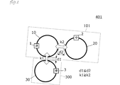
- FIG. 1 is a diagram illustrating a configuration of a wireless power feeding system 401 and a power transmission device according to the first embodiment.
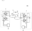
- FIG. 2 is a circuit diagram of the wireless power feeding system 401 of the first embodiment.
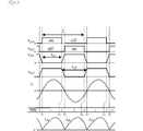
- FIG. 3 is a waveform diagram of each part of FIG.
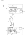
- FIG. 4 is a diagram illustrating a configuration of the wireless power feeding system 402 and the power transmission device according to the second embodiment.
- FIG. 5 is a circuit diagram of the wireless power feeding system 402 of the second embodiment.
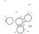
- FIG. 6 is a diagram illustrating a configuration of the wireless power feeding system 403 and the power transmission device according to the third embodiment.
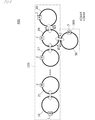
- FIG. 7 is a diagram illustrating a configuration of the wireless power feeding system 404 and the power transmission device according to the fourth embodiment.
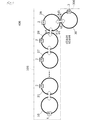
- FIG. 8 is a diagram illustrating configurations of the power transmission device 105 and the wireless power feeding system 405 according to the fifth embodiment.
- FIG. 9 is a diagram illustrating a configuration of the wireless power feeding system 406 and the power transmission device according to the sixth embodiment.
- FIG. 10 is a diagram illustrating a configuration of the wireless power feeding system 407 and the power transmission device according to the seventh embodiment.
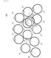
- FIG. 11 is a diagram illustrating a configuration of the wireless power feeding system 408 and the power transmission device according to the eighth embodiment.
- FIG. 12 is a diagram illustrating a configuration of a wireless power feeding system 409 and a power transmission device according to the ninth embodiment.
- FIG. 13 is a schematic front view of a wireless power feeding system 410 according to the tenth embodiment.
- FIG. 14 is a schematic front view of a wireless power feeding system 411 according to the eleventh embodiment.
- First Embodiment a wireless power feeding system in which a relay coil is present and power is supplied from the power transmitting apparatus to the power receiving apparatus without using the relay coil and the power transmitting apparatus will be described.
- FIG. 1 is a diagram illustrating a configuration of a wireless power feeding system 401 and a power transmission device according to the first embodiment.
- the wireless power feeding system 401 is a wireless power feeding system that supplies high-frequency power (hereinafter simply referred to as “power”) from a power transmission device 101 including a power transmission coil 10 to a power reception device 300 including a power reception coil 30 by at least a magnetic field resonance method. .
- the wireless power feeding system 401 includes a circular loop power transmission coil 10, a relay coil 20, and a power reception coil 30.
- the relay coil 20 and the power receiving coil 30 are disposed close to the power transmitting coil 10.
- the relay coil 20 is not disposed between the power transmission coil 10 and the power reception coil 30.
- the coil opening surfaces of the power transmission coil 10, the relay coil 20, and the power reception coil 30 have the same or parallel relationship.
- the power transmission circuit 10 is connected to the power transmission coil 10, and the power reception circuit 3 is connected to the power reception coil 30.
- the power transmission coil 10 and the power reception coil 30 are at least magnetically coupled.
- the power transmission coil 10 and the relay coil 20 are also at least magnetically coupled.
- the relay coil 20 may be coupled with a power receiving coil other than the power receiving coil 30 or another relay coil, but the illustration is omitted in FIG.
- FIG. 2 is a circuit diagram of the wireless power feeding system 401 of the first embodiment.
- the wireless power feeding system 401 is a system that includes an input power source Vi at the input unit of the power transmission circuit 1 and wirelessly supplies stable DC energy to the load Ro of the power receiving circuit 3.
- the power transmission circuit 1 includes a power transmission coil 10, a resonance capacitor Cr, switch elements Q1 and Q2, and a power transmission side switching circuit including a switching control circuit 1C that controls the switch elements Q1 and Q2.
- the power transmission coil 10 and the resonance capacitor Cr constitute a “power transmission side resonance circuit”.
- the switch circuit S1 is composed of a parallel connection circuit of the switch element Q1, the antiparallel diode Dds1, and the parasitic capacitor Cds1.
- a switch circuit S2 is configured by a parallel connection circuit of the switch element Q2, the antiparallel diode Dds2, and the parasitic capacitor Cds2.
- the antiparallel diode (parasitic diode) is simply referred to as “diode”.
- the switching control circuit 1C is connected to the power transmission side resonance circuit, and by alternately turning on and off the switch circuits S1 and S2 at a predetermined switching frequency, the DC power source is intermittently added to the power transmission side resonance circuit to resonate with the power transmission side resonance circuit. Generate current.
- the power transmission side switching circuit constitutes a half-bridge circuit including two switch circuits S1 and S2.
- the relay circuit 2 includes a relay coil 20 and a resonance capacitor Crr.
- the power receiving circuit 3 includes a power receiving coil 30, a resonance capacitor Crs, switching elements Q3 and Q4, a power receiving side switching circuit including a switching control circuit 3C for controlling the switching elements Q3 and Q4, and a smoothing capacitor Co. .
- the power receiving coil 30 and the resonance capacitor Crs equivalently connected in series to it constitute a “power receiving side resonance circuit”.
- Switch circuit S3 is composed of a parallel connection circuit of switch element Q3, diode Dds3, and capacitor Cds3.
- a switch circuit S4 is configured by a parallel connection circuit of the switch element Q4, the diode Dds4, and the capacitor Cds4.
- the switching control circuit 3C detects the current flowing through the power receiving coil 30, and alternately turns on and off the switch elements Q3 and Q4 in synchronization with the polarity inversion. As a result, the resonance current flowing through the power receiving side resonance circuit is rectified in synchronization with the change in the direction of current flow, and the current is supplied to the load.
- These switch circuits S3 and S4 and the switching control circuit 3C constitute a power receiving side rectifier circuit.
- the smoothing capacitor Co smoothes the voltage rectified by the power receiving side rectifier circuit.
- the switching control circuit 1C on the power transmission side operates using the input power source Vi as a power source.
- the power receiving side switching control circuit 3C operates using a voltage generated in the power receiving side resonance circuit, an output voltage to the load, or a power supply source provided separately as a power source.
- the resonance frequency of the power transmission side resonance circuit is set equal to or near the switching frequency of the switching control circuit 1C. Further, the resonance frequency of the power transmission side resonance circuit, the resonance frequency of the relay circuit 2, and the resonance frequency of the power reception side resonance circuit are set to be equal to or close to each other. Since the power transmission side resonance circuit, the relay circuit 2 and the power reception side resonance circuit are coupled to each other to generate multiple resonance, the multiple resonance frequency may be different from the switching frequency.
- the frequency of the alternating magnetic field fed by wireless matches the switching frequency
- the resonance frequency of the relay circuit 2 alone basically matches the operating frequency of the above system, thus simplifying the system. And operate with high efficiency.
- the relay coil 20 and the resonance capacitor Crr constitute a resonance circuit.
- the power transmission coil 10 and the relay coil 20 are electromagnetically coupled, and the relay coil 20 and the power transmission coil 10 are electromagnetically coupled.
- the relay coil 20 and the power transmission coil 10 are electromagnetically coupled.
- All of the power transmission coil 10, the relay coil 20, and the power reception coil 30 are equivalently represented as a circuit constituted by an ideal transformer, a mutual inductance, and a leakage inductance.
- Magnetic resonance coupling occurs due to mutual inductance formed equivalently between the power transmission coil 10 and the relay coil 20, and magnetic resonance coupling occurs due to mutual inductance formed equivalently between the relay coil 20 and the power receiving coil 30.
- power is supplied from the power transmission circuit 1 to the power reception circuit 3.
- the energy (reactive power) reflected without being transmitted from the power transmission circuit 1 is stored as resonance energy in the power transmission side resonance circuit.
- the energy (reactive power) reflected without being supplied to the output among the energy received by the power receiving circuit 3 is also stored as resonance energy in the power receiving side resonance circuit.
- the power transmission coil 10 when the power transmission circuit 1 wirelessly feeds power of 0.1 to 80 W at 6 to 14 MHz over a distance of 2 to 50 mm, the power transmission coil 10 has a radius of 25 mm to 75 mm and a conductor wire diameter of 1 mm to 2 mm, for example. It is an order.
- the power transmission coil 10, the relay coil 20, and the power reception coil 30 can be configured by forming a metal wire in a loop shape or forming a loop-shaped conductor pattern on a circuit board.
- FIG. 3 is a waveform diagram of each part of FIG.
- the mutual inductance of the power transmission coil 10 is Lm
- the leakage inductance of the power transmission coil 10 is Lr
- the mutual inductance of the power reception coil 30 is Lms
- the leakage inductance of the power reception coil 30 is Lrs.
- the gate-source voltages of the switch elements Q1, Q2 are vgs1, vgs2, and the drain-source voltages are vds1, vds2.
- Switch elements Q1 and Q2 are alternately turned on and off with a short dead time when both switch elements are turned off, and the ZVS operation is performed by commutating currents flowing through Q1 and Q2 during the dead time period.
- the operation in each state in one switching cycle is as follows.
- the diode Dds2 becomes conductive.
- the switch element Q2 is turned on during the conduction period of the diode Dds2, a ZVS operation is performed, and the switch element Q2 becomes conductive.
- Equivalent mutual inductances Lm and Lms are formed between the power transmission coil 10 and the power reception coil 30 by mutual induction.
- the circuit resonates, a resonance current flows through the mutual inductances Lm and Lms, and electromagnetic resonance coupling is formed to supply power from the power transmission circuit to the power reception circuit.
- a resonance current flows through the capacitor Cr and the leakage inductance Lr.
- a resonance current flows through the capacitor Crs and the leakage inductance Lrs, and is rectified by the switch elements Q3 and Q4 to supply power to the load.
- Second Embodiment a wireless power feeding system in which power is supplied from a power transmitting device to a power receiving device through a path of the power transmitting device ⁇ the relay coil ⁇ the power receiving device and the power transmitting device will be described.
- FIG. 4 is a diagram illustrating a configuration of the wireless power feeding system 402 and the power transmission device according to the second embodiment.
- the wireless power feeding system 402 is a wireless power feeding system that supplies power from a power transmitting device 102 including the power transmitting coil 10 to a power receiving device 300 including the power receiving coil 30 at least by a magnetic field resonance method.
- the wireless power feeding system 402 includes a circular loop power transmission coil 10, a relay coil 20, and a power reception coil 30.
- the relay coil 20 is disposed close to the power transmission coil 10 and the power reception coil 30.
- the relay coil 20 is disposed between the power transmission coil 10 and the power reception coil 30.
- the coil opening surfaces of the power transmission coil 10, the relay coil 20, and the power reception coil 30 have the same or parallel relationship.
- the power transmission circuit 10 is connected to the power transmission coil 10, and the power reception circuit 3 is connected to the power reception coil 30.
- the power transmission coil 10 and the relay coil 20 are at least magnetically coupled, and the relay coil 20 and the power receiving coil 30 are at least magnetically coupled.
- the relay coil 20 may be coupled with a receiving coil other than the receiving coil 30 or another relay coil, but the illustration is omitted in FIG.
- FIG. 5 is a circuit diagram of the wireless power feeding system 402 of the second embodiment.
- the configurations of the power transmission circuit 1, the relay circuit 2, and the power reception circuit 3 are the same as those shown in the first embodiment.
- the value of k23 is the maximum, and The power supply efficiency to the power receiving apparatus 300 is maximized.
- the coupling coefficient relationship can be expressed as a relationship of d3 ⁇ d2.
- the power receiving coil 30 when the power receiving coil 30 is disposed far away in the arrangement of the power transmission coil 10 and the relay coil 20, that is, power is transmitted through the path of the power transmission coil 10 ⁇ the relay coil 20 ⁇ the power receiving coil 30.
- power is supplied from the device 102 to the power receiving device 300, power is supplied from the power transmitting device 102 to the power receiving device 300 with high efficiency.
- FIG. 6 is a diagram illustrating a configuration of the wireless power feeding system 403 and the power transmission device according to the third embodiment.
- the wireless power feeding system 403 is a wireless power feeding system that supplies power from a power transmitting device 103 including the power transmitting coil 10 to a power receiving device 300 including the power receiving coil 30 by at least a magnetic field resonance method.
- the wireless power feeding system 403 includes a circular loop power transmission coil 10, relay coils 21 and 22, and a power reception coil 30.
- the relay coil 21 is disposed in proximity to the power transmission coil 10 and the power reception coil 30.
- the relay coil 22 is disposed close to the relay coil 21.
- the coil opening surfaces of the power transmission coil 10, the relay coils 21 and 22, and the power reception coil 30 are in agreement or in parallel.
- the power transmission circuit 10 is connected to the power transmission coil 10, and the power reception circuit 3 is connected to the power reception coil 30.
- the power transmission coil 10 and the relay coil 21 are at least magnetically coupled, and the relay coil 21 and the power receiving coil 30 are at least magnetically coupled.
- the relay coil 22 is at least magnetically coupled to the relay coil 21.
- the relay coil 22 may be coupled with a power receiving coil 30, another power receiving coil other than the relay coil 21, or another relay coil, but the illustration is omitted in FIG. 6.
- the relay coil 21 in the present embodiment is an example of the “coupled relay coil” according to the present invention.
- the relay coil 22 is a relay coil on the downstream side of the “coupled relay coil”.
- the configurations of the power transmission circuit 1, the relay circuit 2, and the power reception circuit 3 are the same as the circuits shown in the first and second embodiments.
- FIG. 7 is a diagram illustrating a configuration of the wireless power feeding system 404 and the power transmission device according to the fourth embodiment.
- the wireless power feeding system 404 is a wireless power feeding system that supplies power from a power transmitting device 104 including the power transmitting coil 10 and a plurality of relay coils 21 and 22 to a power receiving device 300 including the power receiving coil 30 by at least a magnetic field resonance method.
- the wireless power feeding system 404 includes a circular loop power transmission coil 10, relay coils 21 and 22, and a power reception coil 30.
- the relay coil 21 is disposed close to the power transmission coil 10 and the relay coil 22.
- the power receiving coil 30 is disposed close to the relay coil 22.
- the coil opening surfaces of the power transmission coil 10, the relay coils 21 and 22, and the power reception coil 30 are in agreement or in parallel.
- the power transmission circuit 10 is connected to the power transmission coil 10, and the power reception circuit 3 is connected to the power reception coil 30.
- the power transmission coil 10 and the relay coil 21 are at least magnetically coupled, and the relay coil 21 and the relay coil 22 are at least magnetically coupled.
- the relay coil 22 and the power receiving coil 30 are at least magnetically coupled.
- the relay coils 21 and 22 may be coupled with the power receiving coil 30, other power receiving coils other than the relay coils 21 and 22, or other relay coils, but the illustration is omitted in FIG. 7.
- the relay coil 22 in the present embodiment is an example of the “coupled relay coil” according to the present invention.
- the relay coil 21 is a relay coil on the upstream side of the “coupled relay coil”.
- the configurations of the power transmission circuit 1, the relay circuit 2, and the power reception circuit 3 are the same as the circuits shown in the first and second embodiments.
- k45 k4 * k5.
- the value of k45 is the maximum, The power supply efficiency from the relay coil 22 to the power receiving device 300 is maximized.
- the coupling coefficient relationship can be expressed by a relationship of d5 ⁇ d4.
- the fifth embodiment is a system that wirelessly supplies power from a power transmitting device to a power receiving device using a plurality of relay coils, and a relay coil (coupled relay coil) that is coupled to the power receiving coil among the plurality of relay coils.
- a wireless power feeding system in which a relay coil is present downstream, and a power transmission device thereof will be described.
- FIG. 8 is a diagram illustrating a configuration of the power transmission device 105 and the wireless power feeding system 405 according to the fifth embodiment.
- the wireless power feeding system 405 includes at least magnetic field resonance from the power transmitting device 105 including the power transmitting coil 10 to the power receiving device 300 including the power receiving coil 30 that is at least magnetically coupled via the plurality of relay coils 21.
- This is a wireless power supply system that supplies power in a system.
- the wireless power feeding system 405 includes a circular loop power transmission coil 10, relay coils 21 to 29, and a power reception coil 30.
- the power receiving coil 30 is disposed close to the relay coil 28.
- the relay coil 29 is not disposed between the power transmission coil 10 and the power reception coil 30.
- the relay coil 28 in this embodiment is an example of the “coupled relay coil” according to the present invention.
- the relay coil 29 is a relay coil on the downstream side of the “coupled relay coil”.
- the configurations of the power transmission circuit 1, the relay circuit 2, and the power reception circuit 3 are the same as the circuits shown in the first and second embodiments.
- the sixth embodiment is a system that wirelessly supplies power from a power transmission device to a power reception device using a plurality of relay coils, and the power reception coil is coupled to the most downstream relay coil among the plurality of relay coils.
- a wireless power feeding system and its power transmission device will be described.
- FIG. 9 is a diagram illustrating a configuration of the wireless power feeding system 406 and the power transmission device according to the sixth embodiment.
- the wireless power feeding system 406 is a wireless power feeding system that supplies power from a power transmitting device 106 including the power transmitting coil 10 and the plurality of relay coils 21 to 29 to the power receiving device 300 including the power receiving coil 30 by at least a magnetic field resonance method.
- the wireless power feeding system 406 includes a circular loop power transmission coil 10, relay coils 21 to 29, and a power reception coil 30.
- the power receiving coil 30 is disposed close to the relay coil 29.
- the power transmission circuit 10 is connected to the power transmission coil 10, and the power reception circuit 3 is connected to the power reception coil 30.
- the power transmission coil 10 and the relay coil 21 are at least magnetically coupled, and adjacent relay coils are also at least magnetically coupled.
- the relay coil 29 and the power receiving coil 30 are at least magnetically coupled.
- the relay coils 21 to 29 may be coupled to the power receiving coil 30, other power receiving coils other than the relay coils 21 to 29, or other relay coils, but the illustration is omitted in FIG.
- the relay coil 29 in the present embodiment is an example of the “coupled relay coil” according to the present invention.
- the relay coil 28 is a relay coil on the upstream side of the “coupled relay coil”.
- the configurations of the power transmission circuit 1, the relay circuit 2, and the power reception circuit 3 are the same as the circuits shown in the first and second embodiments.
- a plurality of relay coils 21 to 29 are arranged between the power transmission coil 10 and the power reception coil 30 by setting the relationship of k5 ⁇ k4 or d5 ⁇ d4. In this case, it is possible to supply power from the power transmission device 106 to the power reception device 300 with high efficiency.
- a wireless power feeding system in which a power receiving coil is coupled to a plurality of relay coils and power is supplied from the power transmitting device to the power receiving device and the power transmitting device will be described.
- FIG. 10 is a diagram illustrating a configuration of the wireless power feeding system 407 and the power transmission device according to the seventh embodiment.
- the wireless power feeding system 407 is a wireless power feeding system that supplies power from a power transmitting device 107 including the power transmitting coil 10 to a power receiving device 300 including the power receiving coil 30 by at least a magnetic field resonance method.
- the wireless power feeding system 407 includes a circular loop power transmission coil 10, relay coils 21 and 22, and a power reception coil 30.
- the relay coil 21 is disposed in proximity to the power transmission coil 10 and the power reception coil 30.
- the relay coil 22 is disposed in proximity to the relay coil 21 and the power receiving coil 30.
- the power transmission circuit 10 is connected to the power transmission coil 10, and the power reception circuit 3 is connected to the power reception coil 30.
- the power transmission coil 10 and the relay coil 21 are at least magnetically coupled, and the relay coil 22 is at least magnetically coupled to the relay coil 21.
- the power receiving coil 30 is at least magnetically coupled to the relay coils 21 and 22.
- the example shown in FIG. 10 is a combination of the wireless power supply system shown in FIG. 6 in the third embodiment and the wireless power supply system shown in FIG. 7 in the fourth embodiment.
- the configurations of the power transmission circuit 1, the relay circuit 2, and the power reception circuit 3 are the same as the circuits shown in the first and second embodiments.
- the coupling coefficient between the relay coil 21 and the receiving coil 30 is represented by k3, the coupling coefficient between the relay coil 22 and the receiving coil 30 is represented by k5, and the coupling coefficient between the relay coil 21 and the relay coil 22. Is represented by k4, k3 ⁇ k4 and k5 ⁇ k4.
- the shortest distance between the relay coil 21 and the power receiving coil 30 is represented by d3
- the shortest distance between the relay coil 22 and the power receiving coil 30 is represented by d5
- the shortest distance between the relay coil 21 and the relay coil 22 is represented by d4, d3 ⁇ d4 and d5 ⁇ d4.
- high-efficiency power supply from the power transmitting apparatus 107 to the power receiving apparatus 300 is achieved by the same effects as the wireless power feeding system according to the third embodiment and the wireless power feeding system according to the fourth embodiment. Is possible.
- a wireless power feeding system that wirelessly supplies power from a power transmission device to a power reception device in relation to at least a part of a coil opening in a plan view with respect to a power transmission coil or a relay coil, and the power transmission device Show.
- FIG. 11 is a diagram illustrating a configuration of the wireless power feeding system 408 and the power transmission device according to the eighth embodiment.
- the wireless power feeding system 408 supplies power from a power transmission device including the power transmission coil 10 to a power reception device including at least a power reception coil 30 that is magnetically coupled via a plurality of relay coils 21 and 28 by at least a magnetic resonance method. It is a wireless power supply system.
- FIG. 11 shows an example in which a large number of relay coils 20 are arranged around the power transmission coil.
- the relay coil is a system that wirelessly supplies power from a power transmission device to a power reception device using a plurality of relay coils, and a relay coil downstream of a relay coil (coupled relay coil) coupled to the power reception coil among the plurality of relay coils.
- a relay coil downstream of a relay coil (coupled relay coil) coupled to the power reception coil among the plurality of relay coils.
- the wireless power feeding system 408 includes a circular loop power transmission coil 10, a plurality of relay coils (20, 21, 28, etc.), and a power receiving coil 30, respectively.
- the power receiving coil 30 is disposed close to the relay coil 28.
- the relay coil 29 is disposed close to the relay coil 28.
- the relay coil 28 in this embodiment is an example of the “coupled relay coil” according to the present invention.
- the relay coil 29 is a relay coil on the downstream side of the “coupled relay coil”.
- the configurations of the power transmission circuit 1, the relay circuit 2, and the power reception circuit 3 are the same as the circuits shown in the first and second embodiments.
- the coupling relay coil 28 is connected to the relay coil 29 on the downstream side.
- the power supply is suppressed, and the power receiving apparatus can efficiently receive power from the coupling relay coil 28.
- the power transmission coil 10 is connected to the relay coil (20 etc.). ) Is suppressed, and the power receiving device can efficiently receive power from the power transmitting device.
- Ninth embodiment a wireless power feeding system that wirelessly supplies power from a power transmitting apparatus to a power receiving apparatus in a relationship in which at least a part of the coil opening overlaps a plurality of relay coils in a plan view, and the power transmitting apparatus will be described. .
- FIG. 12 is a diagram illustrating a configuration of a wireless power feeding system 409 and a power transmission device according to the ninth embodiment.
- the wireless power feeding system 409 is a wireless power feeding system that supplies power from a power transmitting device including the power transmitting coil 10 to a power receiving device including the power receiving coil 30 at least by a magnetic field resonance method.
- the wireless power feeding system 409 includes a circular loop power transmission coil 10, a plurality of relay coils (20, 21, 22, etc.), and a power reception coil 30.
- the power receiving coil 30 is disposed close to the relay coils 21 and 22.
- the relay coil 21 and the relay coil 22 are arranged close to each other.
- the coupling coefficient between the relay coil 21 and the power receiving coil 30 is represented by k3, the coupling coefficient between the relay coil 22 and the power receiving coil 30 is represented by k5, and the coupling coefficient between the relay coil 21 and the relay coil 22 is represented. Is represented by k4, k3 ⁇ k4 and k5 ⁇ k4.
- the power transmission coil 10 Is supplied from the power transmission device including the power receiving device including the power receiving coil 30 with high efficiency.
- FIG. 13 is a schematic front view of a wireless power feeding system 410 according to the tenth embodiment. However, FIG. 13 illustrates the internal configuration of the power transmission device 110 and the power reception device 300.
- the wireless power feeding system 410 includes a power transmission device 110 and a power reception device 300.
- the power transmission device 110 includes a circular loop power transmission coil 10, relay coils 27, 28, and 29, and a housing that houses them.
- the power receiving device 300 includes a circular loop-shaped power receiving coil 30 and a casing that houses the power receiving coil 30.
- the relay coil 27 is magnetically coupled to the power transmission coil 10
- the relay coil 28 is magnetically coupled to the relay coil 27, and the relay coil 29 is magnetically coupled to the relay coil 28.
- the power receiving device 300 includes a power receiving coil 30 and a power receiving circuit 3.
- the power receiving coil 30 is magnetically coupled to any one of the power transmitting coil 10 and the relay coils 27, 28, and 29.
- positioning part P1 in which the power receiving apparatus 300 is mounted is provided in the upper part of the power transmission coil 10 of the power transmission apparatus 110, and the relay coils 27,28,29.
- the power receiving coil 30 is magnetically coupled to any one or a plurality of coils of the power transmitting coil 10 and the relay coils 27, 28, and 29.
- FIG. 14 is a schematic front view of a wireless power feeding system 411 according to the eleventh embodiment. However, FIG. 14 illustrates the internal configuration of the power transmission device 111, the relay device 201, and the power reception device 300.
- the wireless power feeding system 411 includes a first housing H1, and includes the power transmission device 111, the relay device 201, and the power receiving device 300 in the first housing H1.
- Each of the power transmission devices 111 includes a circular loop power transmission coil 10 and relay coils 27 and 28.
- the relay device 201 includes a second housing H2, and includes the relay coil 29 and the relay circuit 2 in the second housing H2.
- the power receiving device 300 includes a power receiving coil 30 and a power receiving circuit 3.
- the relay coil 27 is magnetically coupled to the power transmission coil 10, and the relay coil 28 is magnetically coupled to the relay coil 27.
- positioning part P1 in which the power receiving apparatus 300 is mounted is provided in the upper part of the relay coil 28 of the power transmission apparatus 111. As shown in FIG. When the power receiving device 300 is placed on the first placement portion P1, the power receiving coil 30 is magnetically coupled to the relay coil 28.
- a second arrangement portion P2 in which the relay device or the power receiving device is juxtaposed is provided on the side portion of the relay coil 28 of the power transmission device 111.
- the relay device 201 is juxtaposed on the second placement unit P2.
- a third placement portion P3 on which the power receiving device is placed is provided on the upper surface of the relay device 201.
- the power transmission coil 10, the relay coil (20 to 29, etc.), and the power reception coil 30 all have the same diameter and their winding axes are in agreement or in parallel.
- the power transmission coil 10, the relay coil (20 to 29, etc.), and the power receiving coil 30 are not limited to these relationships. Even if adjacent coils are non-parallel, the diameters are different, the winding axis is not coaxial, and even if the winding axis is in a “twisted position” relationship, the same applies. .
- the coil opening surface is not limited to a flat surface but may be a curved surface.
- a sheet-like coil in which a coil conductor pattern is formed on a flexible substrate may be arranged along a curved surface.
- the two members that define the distance are divided into minute sections, The minimum distance of the distances between the minute sections is defined as the “shortest distance”, and the same effect can be obtained by satisfying the above condition for the “shortest distance”.
Landscapes
- Engineering & Computer Science (AREA)
- Computer Networks & Wireless Communication (AREA)
- Power Engineering (AREA)
- Charge And Discharge Circuits For Batteries Or The Like (AREA)
- Near-Field Transmission Systems (AREA)
Abstract
送電コイル(10)を備える送電装置(101)から、送電コイル(10)に対して少なくとも磁界結合する受電コイル(30)を備える受電装置へ、ワイヤレスで高周波電力を供給する、磁界共鳴技術を用いたワイヤレス給電システムにおいて、送電コイル(10)および受電コイル(30)に対して少なくとも磁界を用いて結合する中継コイル(20)と、中継コイル(20)に接続されて、中継コイル(20)とともに共振回路を構成する中継回路(2)と、を備え、送電コイル(10)と受電コイル(30)との結合係数をk1で表し、送電コイル(10)と中継コイル(20)との結合係数をk2で表すとき、k1≧k2の関係にある。
Description
本発明は、高周波電力を送電装置から受電装置へ供給するワイヤレス給電システムおよびその送電装置に関する発明である。
電磁誘導方式、磁界共鳴方式、直流共鳴方式等の磁界結合型のワイヤレス給電システムにおいては、送電装置の送電コイルと受電装置の受電コイルとが磁界を用いて結合することで送電が行われる。例えば特許文献1には、受電装置を送電装置上のどの位置においても電力を受電できるように、複数の送電ユニット(送電コイル+送電駆動回路等)を備えたシステムが示されている。
上記送電装置と受電装置は、それらが所定の位置関係に配置されることで、送電装置が備える送電コイルと、受電装置が備える受電コイルとが磁界結合するように構成されている。
しかし、特許文献1に示される送電装置は、それぞれ電源回路に電気的に接続された複数の送電ユニットを備える。このような構成の場合、複数の送電駆動回路や複雑な配線が必要となり、システムは複雑になる。送電装置の送電面の面積を大きくすることは、複数の送電駆動回路や複雑な配線を備えることになり、システムは大型化し、コストが非常に嵩むことになる。
そこで、本発明の目的は、送電駆動回路等のコストが掛かる回路をそれぞれ備える多数の送電ユニットを複数台設けることなく、できるだけ少ない送電装置や送電回路を用いた簡素な構成で、広い範囲、広い面積において、電力損失を少なく、電力効率を高くして、ワイヤレスで電力を供給できるワイヤレス給電システムおよびその送電装置を提供することにある。
(1)本発明のワイヤレス給電システムは、
送電コイルを備える送電装置から、前記送電コイルに対して少なくとも磁界結合する受電コイルを備える受電装置へ、ワイヤレスで高周波電力を供給する、磁界共鳴技術を用いたワイヤレス給電システムであり、
前記送電コイルおよび前記受電コイルに対して少なくとも磁界を用いて結合する中継コイルと、
前記中継コイルに接続されて、前記中継コイルとともに共振回路を構成する中継回路と、を備え、
前記送電コイルと前記受電コイルとの結合係数をk1で表し、前記送電コイルと前記中継コイルとの結合係数をk2で表すとき、k1≧k2の関係にある、ことを特徴とする。
送電コイルを備える送電装置から、前記送電コイルに対して少なくとも磁界結合する受電コイルを備える受電装置へ、ワイヤレスで高周波電力を供給する、磁界共鳴技術を用いたワイヤレス給電システムであり、
前記送電コイルおよび前記受電コイルに対して少なくとも磁界を用いて結合する中継コイルと、
前記中継コイルに接続されて、前記中継コイルとともに共振回路を構成する中継回路と、を備え、
前記送電コイルと前記受電コイルとの結合係数をk1で表し、前記送電コイルと前記中継コイルとの結合係数をk2で表すとき、k1≧k2の関係にある、ことを特徴とする。
また、前記送電コイルと前記受電コイルとの最短距離をd1で表し、前記送電コイルと前記中継コイルとの最短距離をd2で表すとき、d1≦d2の関係にある、ことを特徴とする。
上記構成により、送電コイルから中継コイルへの電力供給が抑制されて、受電装置は送電装置から電力を効率良く受電できる。
(2)本発明のワイヤレス給電システムは、
送電コイルを備える送電装置から、前記送電コイルに対して少なくとも磁界結合する受電コイルを備える受電装置へ、ワイヤレスで高周波電力を供給する、磁界共鳴技術を用いたワイヤレス給電システムであり、
前記送電コイルおよび前記受電コイルに対して少なくとも磁界を用いて結合する中継コイルと、
前記中継コイルに接続されて、前記中継コイルとともに共振回路を構成する中継回路と、を備え、
前記送電コイルと前記中継コイルとの結合係数をk2で表し、前記受電コイルと前記中継コイルとの結合係数をk3で表すとき、k3≧k2の関係にある、ことを特徴とする。
送電コイルを備える送電装置から、前記送電コイルに対して少なくとも磁界結合する受電コイルを備える受電装置へ、ワイヤレスで高周波電力を供給する、磁界共鳴技術を用いたワイヤレス給電システムであり、
前記送電コイルおよび前記受電コイルに対して少なくとも磁界を用いて結合する中継コイルと、
前記中継コイルに接続されて、前記中継コイルとともに共振回路を構成する中継回路と、を備え、
前記送電コイルと前記中継コイルとの結合係数をk2で表し、前記受電コイルと前記中継コイルとの結合係数をk3で表すとき、k3≧k2の関係にある、ことを特徴とする。
また、前記送電コイルと前記中継コイルとの最短距離をd2で表し、前記受電コイルと前記中継コイルとの最短距離をd3で表すとき、d3≦d2の関係にあることを特徴とする。
上記構成により、受電コイルが、送電コイルと中継コイルとの配列での遠方に配置されている場合に、送電装置から受電装置へ、高効率で電力損失の少ない電力供給が可能となる。ここで、送電コイルと受電コイルとの結合係数をk23で表すと、k23=k2*k3の関係で表すことができ、k3=k2のとき、k23の値は最大となり、送電装置から受電装置への電力供給効率は最大となる。但し、中継コイルでの損失分を考慮すると、k3=k2ではなく、k3>k2となる条件で、送電装置から受電装置への電力供給効率は最大となる。したがって、上記のとおり、k3≧k2の関係にあることが好ましい。物理的なコイルの形状、または大きさなどが類似している場合において、この結合係数の関係を距離の関係で言い換えると、d3≦d2の関係にあることが好ましい。
(3)本発明のワイヤレス給電システムは、
送電コイルを備える送電装置から、前記送電コイルに対して少なくとも磁界結合する受電コイルを備える受電装置へ、ワイヤレスで高周波電力を供給する、磁界共鳴技術を用いたワイヤレス給電システムであり、
複数の中継コイルと、
前記複数の中継コイルにそれぞれ接続されて、前記中継コイルとともに共振回路をそれぞれ構成する中継回路と、を備え、
前記複数の中継コイルは、隣接する中継コイル同士で少なくとも磁界を用いて結合し、前記複数の中継コイルの一つは前記送電コイルと少なくとも磁界を用いて結合し、前記複数の中継コイルの一つは前記受電コイルと少なくとも磁界を用いて結合する結合中継コイルであり、
前記結合中継コイルと前記受電コイルとの結合係数をk3で表し、前記複数の中継コイルのうち前記結合中継コイルより下流側の中継コイルと前記結合中継コイルとの結合係数をk4で表すとき、k3≧k4の関係にある、ことを特徴とする。
送電コイルを備える送電装置から、前記送電コイルに対して少なくとも磁界結合する受電コイルを備える受電装置へ、ワイヤレスで高周波電力を供給する、磁界共鳴技術を用いたワイヤレス給電システムであり、
複数の中継コイルと、
前記複数の中継コイルにそれぞれ接続されて、前記中継コイルとともに共振回路をそれぞれ構成する中継回路と、を備え、
前記複数の中継コイルは、隣接する中継コイル同士で少なくとも磁界を用いて結合し、前記複数の中継コイルの一つは前記送電コイルと少なくとも磁界を用いて結合し、前記複数の中継コイルの一つは前記受電コイルと少なくとも磁界を用いて結合する結合中継コイルであり、
前記結合中継コイルと前記受電コイルとの結合係数をk3で表し、前記複数の中継コイルのうち前記結合中継コイルより下流側の中継コイルと前記結合中継コイルとの結合係数をk4で表すとき、k3≧k4の関係にある、ことを特徴とする。
また、前記結合中継コイルと前記受電コイルとの最短距離をd3で表し、前記複数の中継コイルのうち前記結合中継コイルより下流側の中継コイルと前記結合中継コイルとの最短距離をd4で表すとき、d3≦d4の関係にあることを特徴とする。
上記構成により、結合中継コイルからその下流側の中継コイルへの電力供給が抑制されて、受電装置は結合中継コイルから電力を効率良く受電できる。
(4)本発明のワイヤレス給電システムは、
送電コイルを備える送電装置から、前記送電コイルに対して少なくとも磁界結合する受電コイルを備える受電装置へ、ワイヤレスで高周波電力を供給する、磁界共鳴技術を用いたワイヤレス給電システムであり、
複数の中継コイルと、
前記複数の中継コイルにそれぞれ接続されて、前記中継コイルとともに共振回路をそれぞれ構成する中継回路と、を備え、
前記複数の中継コイルは、隣接する中継コイル同士で少なくとも磁界を用いて結合し、前記複数の中継コイルの一つは前記送電コイルと少なくとも磁界を用いて結合し、前記複数の中継コイルの一つは前記受電コイルと少なくとも磁界を用いて結合する結合中継コイルであり、
前記複数の中継コイルのうち前記結合中継コイルより上流側の中継コイルと前記結合中継コイルとの結合係数をk4で表し、前記結合中継コイルと前記受電コイルとの結合係数をk5で表すとき、k5≧k4の関係にある、ことを特徴とする。
送電コイルを備える送電装置から、前記送電コイルに対して少なくとも磁界結合する受電コイルを備える受電装置へ、ワイヤレスで高周波電力を供給する、磁界共鳴技術を用いたワイヤレス給電システムであり、
複数の中継コイルと、
前記複数の中継コイルにそれぞれ接続されて、前記中継コイルとともに共振回路をそれぞれ構成する中継回路と、を備え、
前記複数の中継コイルは、隣接する中継コイル同士で少なくとも磁界を用いて結合し、前記複数の中継コイルの一つは前記送電コイルと少なくとも磁界を用いて結合し、前記複数の中継コイルの一つは前記受電コイルと少なくとも磁界を用いて結合する結合中継コイルであり、
前記複数の中継コイルのうち前記結合中継コイルより上流側の中継コイルと前記結合中継コイルとの結合係数をk4で表し、前記結合中継コイルと前記受電コイルとの結合係数をk5で表すとき、k5≧k4の関係にある、ことを特徴とする。
また、前記複数の中継コイルのうち前記結合中継コイルより上流側の中継コイルと前記結合中継コイルとの最短距離をd4で表し、前記結合中継コイルと前記受電コイルとの最短距離をd5で表すとき、d5≦d4の関係にある、ことを特徴とする。
上記構成により、送電コイルと受電コイルとの間に複数の中継コイルが存在する場合においても、送電装置から受電装置への電力伝送が可能となる。ここで、結合中継コイルと受電コイルとの結合係数をk45で表すと、k45=k4*k5の関係で表すことができ、k5=k4のとき、k45の値は最大となり、結合中継コイルから受電装置への電力供給効率は最大となる。但し、上流側の中継コイルでの損失分を考慮すると、k5=k4ではなく、k5>k4となる条件で、結合中継コイルから受電装置への電力供給効率は最大となる。したがって、上記のとおり、k5≧k4の関係にあることが好ましい。この結合係数の関係を距離の関係で言い換えると、d5≦d4の関係にあることが好ましい。
本発明によれば、送電駆動回路等のコストが掛かる回路をそれぞれ備える多数の送電ユニットを複数台設けることなく、できるだけ少ない送電装置や送電回路を用いた簡素な構成で、広い範囲、広い面積において、電力損失を少なく、電力効率を高くして、ワイヤレスで電力を供給できるワイヤレス給電システムおよびその送電装置が得られる。
以降、図を参照して幾つかの具体的な例を挙げて、本発明を実施するための複数の形態を示す。各図中には同一箇所に同一符号を付している。要点の説明または理解の容易性を考慮して、便宜上実施形態を分けて示すが、異なる実施形態で示した構成の部分的な置換または組み合わせは可能である。第2の実施形態以降では第1の実施形態と共通の事柄についての記述を省略し、異なる点についてのみ説明する。特に、同様の構成による同様の作用効果については実施形態毎には逐次言及しない。
《第1の実施形態》
第1の実施形態では、中継コイルが存在し、且つ、この中継コイルを介さずに、送電装置から受電装置へ電力供給されるワイヤレス給電システムおよびその送電装置について示す。
第1の実施形態では、中継コイルが存在し、且つ、この中継コイルを介さずに、送電装置から受電装置へ電力供給されるワイヤレス給電システムおよびその送電装置について示す。
図1は第1の実施形態に係るワイヤレス給電システム401および送電装置の構成を示す図である。このワイヤレス給電システム401は、送電コイル10を備える送電装置101から、受電コイル30を備える受電装置300へ、少なくとも磁界共鳴方式で高周波電力(以下、単に「電力」)を供給するワイヤレス給電システムである。
図1に表れているように、例えば、ワイヤレス給電システム401は、それぞれ円形ループ状の送電コイル10、中継コイル20および受電コイル30を備える。中継コイル20および受電コイル30は送電コイル10に近接配置されている。中継コイル20は送電コイル10と受電コイル30との間には配置されていない。この例では、送電コイル10、中継コイル20および受電コイル30のそれぞれのコイル開口面は一致または平行関係にある。
送電コイル10には送電回路1が接続されていて、受電コイル30には受電回路3が接続されている。送電コイル10と受電コイル30とは少なくとも磁界結合する。送電コイル10と中継コイル20とについても、それらは少なくとも磁界結合する。中継コイル20には受電コイル30以外の他の受電コイルまたは他の中継コイルが結合する場合があるが、図1では図示を省略している。
図2は第1の実施形態のワイヤレス給電システム401の回路図である。
ワイヤレス給電システム401は、送電回路1の入力部に入力電源Viを備え、受電回路3の負荷Roへ安定した直流のエネルギーをワイヤレスで供給するシステムである。
送電回路1は、送電コイル10と、共振キャパシタCrと、スイッチ素子Q1,Q2と、これらスイッチ素子Q1,Q2を制御するスイッチング制御回路1Cを含む送電側スイッチング回路とを備えている。
送電コイル10と共振キャパシタCrとで「送電側共振回路」が構成されている。
スイッチ素子Q1、逆並列ダイオードDds1および寄生キャパシタCds1の並列接続回路でスイッチ回路S1が構成されている。同様に、スイッチ素子Q2、逆並列ダイオードDds2および寄生キャパシタCds2の並列接続回路でスイッチ回路S2が構成されている。以下、逆並列ダイオード(寄生ダイオード)を単に「ダイオード」という。
スイッチング制御回路1Cは送電側共振回路に接続され、スイッチ回路S1,S2を所定のスイッチング周波数で交互にオンオフさせることにより、直流電源を送電側共振回路に断続的に加えて送電側共振回路に共振電流を発生させる。
この例では、送電側スイッチング回路は2つのスイッチ回路S1,S2を備えたハーフブリッジ回路を構成している。
中継回路2は、中継コイル20と共振キャパシタCrrとで構成されている。
受電回路3は、受電コイル30と、共振キャパシタCrsと、スイッチ素子Q3,Q4と、スイッチ素子Q3,Q4を制御するスイッチング制御回路3Cを含む受電側スイッチング回路と、平滑キャパシタCoとを備えている。
受電コイル30と、それに等価的に直列に接続された共振キャパシタCrsとで「受電側共振回路」が構成されている。
スイッチ素子Q3、ダイオードDds3およびキャパシタCds3の並列接続回路でスイッチ回路S3が構成されている。同様に、スイッチ素子Q4、ダイオードDds4およびキャパシタCds4の並列接続回路でスイッチ回路S4が構成されている。
スイッチング制御回路3Cは受電コイル30に流れる電流を検出し、その極性反転に同期してスイッチ素子Q3,Q4を交互にオンオフする。これにより、受電側共振回路に流れる共振電流が電流の流れる方向の変化に同期して整流されて、負荷に電流が供給される。これらのスイッチ回路S3,S4およびスイッチング制御回路3Cで受電側整流回路が構成されている。平滑キャパシタCoは受電側整流回路で整流された電圧を平滑する。
送電側のスイッチング制御回路1Cは入力電源Viを電源にして動作する。受電側のスイッチング制御回路3Cは、受電側共振回路に発生する電圧、負荷への出力電圧、または別途設けられた電力供給源などを電源にして動作する。
例えば、上記送電側共振回路の共振周波数は、スイッチング制御回路1Cのスイッチング周波数に等しいか、その近傍に設定される。また、送電側共振回路の共振周波数、中継回路2の共振周波数、受電側共振回路の共振周波数、はそれぞれ等しいか、それらの近傍に設定される。送電側共振回路、中継回路2および受電側共振回路は互いに結合して複共振が生じるので、複共振周波数は上記スイッチング周波数とは異なる場合がある。一方、ワイヤレスで給電される交番磁界の周波数(システムの動作周波数)はスイッチング周波数に一致し、中継回路2単体での共振周波数は上記システムの動作周波数に、基本的に一致させることでシステムをシンプルにし、高効率に動作させる。
中継コイル20と共振キャパシタCrrとで共振回路が構成されている。送電コイル10と中継コイル20とは電磁界共鳴結合し、中継コイル20と送電コイル10とは電磁界共鳴結合する。このように、送電コイル10と受電コイル30との間に中継コイル20を配置することで、送電回路1と受電回路3との送電可能最大距離が拡大される。
送電コイル10、中継コイル20および受電コイル30はいずれも、等価的には、理想トランス、相互インダクタンスおよび漏れインダクタンスで構成された回路として表される。
送電コイル10と中継コイル20との間に等価的に形成される相互インダクタンスで磁界共鳴結合が生じ、中継コイル20と受電コイル30との間に等価的に形成される相互インダクタンスで磁界共鳴結合が生じて、送電回路1から受電回路3へ電力が供給される。送電回路1から送電されずに反射したエネルギー(無効電力)は送電側共振回路に共振エネルギーとして保存される。また、受電回路3が受電したエネルギーのうち出力に供給されずに反射したエネルギー(無効電力)も受電側共振回路に共振エネルギーとして保存される。
送電回路1が例えば、6~14MHzで0.1~80Wの電力を2~50mmの距離でワイヤレス給電する場合、送電コイル10は例えば半径は25mm以上75mm以下、導体線の線径は1mm以上2mm以下のオーダーである。
送電コイル10、中継コイル20および受電コイル30は、金属線をループ状に成形することで、または回路基板にループ状の導体パターンを形成することで構成できる。
図1に示すように、送電コイル10と受電コイル30との最短距離をd1で表し、送電コイル10と中継コイル20との最短距離をd2で表すとき、d1≦d2の関係にある。また、送電コイル10と受電コイル30との結合係数をk1で表し、送電コイル10と中継コイル20との結合係数をk2で表すとき、k1≧k2の関係にある。
上記構成により、送電コイル10から中継コイル20への電力供給が抑制されて、受電装置300は送電装置101から電力を効率良く受電できる。
次に、図2に示したワイヤレス給電システム401の詳細な動作を、図3を参照して説明する。図3は図2の各部の波形図である。
送電コイル10の相互インダクタンスをLm、送電コイル10の漏れインダクタンスをLr、受電コイル30の相互インダクタンスをLms、受電コイル30の漏れインダクタンスをLrsとする。また、スイッチ素子Q1,Q2のゲート・ソース間電圧をvgs1,vgs2、ドレイン・ソース間電圧をvds1,vds2とする。
スイッチ素子Q1,Q2は、両スイッチ素子がオフとなる短いデットタイムを挟んで交互にオンオフされ、デットタイム期間にQ1,Q2に流れる電流をそれぞれ転流させてZVS動作を行う。1スイッチング周期における各状態での動作は次のとおりである。
(1) 状態1 時刻t1~t2
先ず、ダイオードDds1が導通する。ダイオードDds1の導通期間においてスイッチ素子Q1をターンオンすることでZVS動作が行われ、スイッチ素子Q1は導通する。送電コイル10と受電コイル30との間に相互誘導によって等価的な相互インダクタンスLm,Lmsが形成され、Cr,Lr,Lm,Lms,Crs,Lrsからなる複共振回路において、送電共振回路と受電共振回路とが共鳴して、相互インダクタンスLm,Lmsに共振電流が流れ、電磁界共鳴結合を形成して、送電回路から受電回路へ電力が供給される。送電側では、キャパシタCr、漏れインダクタンスLrに共振電流が流れる。受電側では、キャパシタCrsおよび漏れインダクタンスLrsに共振電流が流れ、スイッチ素子Q3,Q4により整流されて負荷に電力が供給される。
先ず、ダイオードDds1が導通する。ダイオードDds1の導通期間においてスイッチ素子Q1をターンオンすることでZVS動作が行われ、スイッチ素子Q1は導通する。送電コイル10と受電コイル30との間に相互誘導によって等価的な相互インダクタンスLm,Lmsが形成され、Cr,Lr,Lm,Lms,Crs,Lrsからなる複共振回路において、送電共振回路と受電共振回路とが共鳴して、相互インダクタンスLm,Lmsに共振電流が流れ、電磁界共鳴結合を形成して、送電回路から受電回路へ電力が供給される。送電側では、キャパシタCr、漏れインダクタンスLrに共振電流が流れる。受電側では、キャパシタCrsおよび漏れインダクタンスLrsに共振電流が流れ、スイッチ素子Q3,Q4により整流されて負荷に電力が供給される。
スイッチ素子Q1がターンオフすると状態2となる。
(2) 状態2 時刻t2~t3
送電回路1側では、漏れインダクタンスLrに流れていた電流irにより、寄生キャパシタCds1が充電され、寄生キャパシタCds2は放電される。電圧vds1が入力電源Viの電圧になり、電圧vds2が0VになるとダイオードDds2が導通して状態3となる。
送電回路1側では、漏れインダクタンスLrに流れていた電流irにより、寄生キャパシタCds1が充電され、寄生キャパシタCds2は放電される。電圧vds1が入力電源Viの電圧になり、電圧vds2が0VになるとダイオードDds2が導通して状態3となる。
(3) 状態3 時刻t3~t4
先ず、ダイオードDds2が導通する。ダイオードDds2の導通期間においてスイッチ素子Q2をターンオンすることでZVS動作が行われ、スイッチ素子Q2は導通する。送電コイル10と受電コイル30との間に相互誘導によって等価的な相互インダクタンスLm,Lmsが形成され、Cr,Lr,Lm,Lms,Crs,Lrsからなる複共振回路において、送電共振回路と受電共振回路とが共鳴して、相互インダクタンスLm,Lmsに共振電流が流れ、電磁界共鳴結合を形成して送電回路から受電回路へ電力が供給される。送電側では、キャパシタCr、漏れインダクタンスLrに共振電流が流れる。受電側では、キャパシタCrs、漏れインダクタンスLrsに共振電流が流れ、スイッチ素子Q3,Q4により整流されて負荷に電力が供給される。
先ず、ダイオードDds2が導通する。ダイオードDds2の導通期間においてスイッチ素子Q2をターンオンすることでZVS動作が行われ、スイッチ素子Q2は導通する。送電コイル10と受電コイル30との間に相互誘導によって等価的な相互インダクタンスLm,Lmsが形成され、Cr,Lr,Lm,Lms,Crs,Lrsからなる複共振回路において、送電共振回路と受電共振回路とが共鳴して、相互インダクタンスLm,Lmsに共振電流が流れ、電磁界共鳴結合を形成して送電回路から受電回路へ電力が供給される。送電側では、キャパシタCr、漏れインダクタンスLrに共振電流が流れる。受電側では、キャパシタCrs、漏れインダクタンスLrsに共振電流が流れ、スイッチ素子Q3,Q4により整流されて負荷に電力が供給される。
スイッチ素子Q2がターンオフすると状態4となる。
(4) 状態4 時刻t4~t1
送電回路1側では、漏れインダクタンスLrに流れていた電流irにより、寄生キャパシタCds1は放電され、寄生キャパシタCds2は充電される。電圧vds1が0V、電圧vds2が入力電源Viの電圧になるとダイオードDds1は導通して再び状態1となる。
送電回路1側では、漏れインダクタンスLrに流れていた電流irにより、寄生キャパシタCds1は放電され、寄生キャパシタCds2は充電される。電圧vds1が0V、電圧vds2が入力電源Viの電圧になるとダイオードDds1は導通して再び状態1となる。
以後、状態1~4を周期的に繰り返す。
《第2の実施形態》
第2の実施形態では、送電装置→中継コイル→受電装置の経路で送電装置から受電装置への電力供給されるワイヤレス給電システムおよびその送電装置について示す。
第2の実施形態では、送電装置→中継コイル→受電装置の経路で送電装置から受電装置への電力供給されるワイヤレス給電システムおよびその送電装置について示す。
図4は第2の実施形態に係るワイヤレス給電システム402および送電装置の構成を示す図である。このワイヤレス給電システム402は、送電コイル10を備える送電装置102から、受電コイル30を備える受電装置300へ、少なくとも磁界共鳴方式で電力を供給するワイヤレス給電システムである。
図4に表れているように、ワイヤレス給電システム402は、それぞれ円形ループ状の送電コイル10、中継コイル20および受電コイル30を備える。中継コイル20は送電コイル10および受電コイル30に近接配置されている。中継コイル20は送電コイル10と受電コイル30との間に配置されている。この例では、送電コイル10、中継コイル20および受電コイル30のそれぞれのコイル開口面は一致または平行関係にある。
送電コイル10には送電回路1が接続されていて、受電コイル30には受電回路3が接続されている。送電コイル10と中継コイル20とは少なくとも磁界結合し、中継コイル20と受電コイル30とは少なくとも磁界結合する。中継コイル20には受電コイル30以外の他の受電コイルまたは他の中継コイルが結合する場合があるが、図4では図示を省略している。
図5は第2の実施形態のワイヤレス給電システム402の回路図である。送電回路1、中継回路2および受電回路3の構成は第1の実施形態で示した回路と同じである。
図4に示すように、送電コイル10と中継コイル20との最短距離をd2で表し、中継コイル20と受電コイル30との最短距離をd3で表すとき、d3≦d2の関係にある。また、送電コイル10と中継コイル20との結合係数をk2で表し、中継コイル20と受電コイル30との結合係数をk3で表すとき、k3≧k2の関係にある。
ここで、送電コイル10と受電コイル30との結合係数をk23で表すと、k23=k2*k3の関係で表すことができ、k3=k2のとき、k23の値は最大となり、送電装置102から受電装置300への電力供給効率は最大となる。但し、中継コイルでの損失分を考慮すると、k3=k2ではなく、k3>k2となる条件で、送電装置101から受電装置300への電力供給効率は最大となる。したがって、上記のとおり、k3≧k2の関係にあることが好ましい。この結合係数の関係を距離の関係で言い換えると、d3≦d2の関係で表すことができる。
本実施形態によれば、受電コイル30が、送電コイル10と中継コイル20との配列での遠方に配置されている場合に、すなわち、送電コイル10→中継コイル20→受電コイル30の経路で送電装置102から受電装置300への電力供給される場合に、送電装置102から受電装置300へ高効率で電力が供給される。
《第3の実施形態》
第3の実施形態では、複数の中継コイルを有し、送電コイルに近い側の中継コイルに受電コイルが結合するワイヤレス給電システムおよびその送電装置について示す。
第3の実施形態では、複数の中継コイルを有し、送電コイルに近い側の中継コイルに受電コイルが結合するワイヤレス給電システムおよびその送電装置について示す。
図6は第3の実施形態に係るワイヤレス給電システム403および送電装置の構成を示す図である。このワイヤレス給電システム403は、送電コイル10を備える送電装置103から、受電コイル30を備える受電装置300へ、少なくとも磁界共鳴方式で電力を供給するワイヤレス給電システムである。
図6に表れているように、ワイヤレス給電システム403は、それぞれ円形ループ状の送電コイル10、中継コイル21,22および受電コイル30を備える。中継コイル21は送電コイル10および受電コイル30に近接配置されている。中継コイル22は中継コイル21に近接配置されている。この例では、送電コイル10、中継コイル21,22および受電コイル30のそれぞれのコイル開口面は一致または平行関係にある。
送電コイル10には送電回路1が接続されていて、受電コイル30には受電回路3が接続されている。送電コイル10と中継コイル21とは少なくとも磁界結合し、中継コイル21と受電コイル30とは少なくとも磁界結合する。中継コイル22は中継コイル21と少なくとも磁界結合する。中継コイル22には受電コイル30、中継コイル21以外の他の受電コイルまたは他の中継コイルが結合する場合があるが、図6では図示を省略している。本実施形態における中継コイル21は本発明に係る「結合中継コイル」の一例である。また、中継コイル22は「結合中継コイル」の下流側の中継コイルである。
送電回路1、中継回路2および受電回路3の構成は第1、第2の実施形態で示した回路と同じである。
図6に示すように、結合中継コイル21と受電コイル30との最短距離をd3で表し、結合中継コイル21と下流側の中継コイル22との最短距離をd4で表すとき、d3≦d4の関係にある。また、結合中継コイル21と受電コイル30との結合係数をk3で表し、結合中継コイル21と中継コイル22との結合係数をk4で表すとき、k3≧k4の関係にある。
上記構成により、結合中継コイル21からその下流側の中継コイル22への電力供給が抑制されて、受電装置300は結合中継コイル21から電力を効率良く受電できる。
《第4の実施形態》
第4の実施形態では、複数の中継コイルを経由して受電装置が受電するワイヤレス給電システムおよびその送電装置について示す。
第4の実施形態では、複数の中継コイルを経由して受電装置が受電するワイヤレス給電システムおよびその送電装置について示す。
図7は第4の実施形態に係るワイヤレス給電システム404および送電装置の構成を示す図である。このワイヤレス給電システム404は、送電コイル10および複数の中継コイル21,22を備える送電装置104から、受電コイル30を備える受電装置300へ、少なくとも磁界共鳴方式で電力を供給するワイヤレス給電システムである。
図7に表れているように、ワイヤレス給電システム404は、それぞれ円形ループ状の送電コイル10、中継コイル21,22および受電コイル30を備える。中継コイル21は送電コイル10および中継コイル22に近接配置されている。受電コイル30は中継コイル22に近接配置されている。この例では、送電コイル10、中継コイル21,22および受電コイル30のそれぞれのコイル開口面は一致または平行関係にある。
送電コイル10には送電回路1が接続されていて、受電コイル30には受電回路3が接続されている。送電コイル10と中継コイル21とは少なくとも磁界結合し、中継コイル21と中継コイル22とは少なくとも磁界結合する。中継コイル22と受電コイル30とは少なくとも磁界結合する。中継コイル21,22には受電コイル30、中継コイル21,22以外の他の受電コイルまたは他の中継コイルが結合する場合があるが、図7では図示を省略している。本実施形態における中継コイル22は本発明に係る「結合中継コイル」の一例である。また、中継コイル21は「結合中継コイル」の上流側の中継コイルである。
送電回路1、中継回路2および受電回路3の構成は第1、第2の実施形態で示した回路と同じである。
図7に示すように、結合中継コイル22と上流側の中継コイル21との最短距離をd4で表し、結合中継コイル22と受電コイル30との最短距離をd5で表すとき、d5≦d4の関係にある。また、結合中継コイル22と上流側の中継コイル21との結合係数をk4で表し、結合中継コイル22と受電コイル30との結合係数をk5で表すとき、k5≧k4の関係にある。
ここで、上流側の中継コイル21と受電コイル30との結合係数をk45で表すと、k45=k4*k5の関係で表すことができ、k5=k4のとき、k45の値は最大となり、結合中継コイル22から受電装置300への電力供給効率は最大となる。但し、上流側の中継コイルでの損失分を考慮すると、k5=k4ではなく、k5>k4となる条件で、結合中継コイルから受電装置への電力供給効率は最大となる。したがって、上記のとおり、k5≧k4の関係にあることが好ましい。この結合係数の関係を距離の関係で言い換えると、d5≦d4の関係で表すことができる。
本実施形態によれば、送電コイル10と受電コイル30との間に複数の中継コイル21,22が配置されている場合に、送電装置104から受電装置300への高効率での電力供給が可能となる。
《第5の実施形態》
第5の実施形態では、複数の中継コイルを用いて送電装置から受電装置へワイヤレスで電力を供給するシステムであり、且つ、複数の中継コイルのうち受電コイルと結合する中継コイル(結合中継コイル)の下流に中継コイルが存在するワイヤレス給電システム、およびその送電装置について示す。
第5の実施形態では、複数の中継コイルを用いて送電装置から受電装置へワイヤレスで電力を供給するシステムであり、且つ、複数の中継コイルのうち受電コイルと結合する中継コイル(結合中継コイル)の下流に中継コイルが存在するワイヤレス給電システム、およびその送電装置について示す。
図8は第5の実施形態に係る送電装置105およびワイヤレス給電システム405の構成を示す図である。このワイヤレス給電システム405は、送電コイル10を備える送電装置105から、複数の中継コイル21・・・27,28を経由して、少なくとも磁界結合する受電コイル30を備える受電装置300へ、少なくとも磁界共鳴方式で電力を供給するワイヤレス給電システムである。
図8に表れているように、ワイヤレス給電システム405は、それぞれ円形ループ状の送電コイル10、中継コイル21~29および受電コイル30を備える。受電コイル30は中継コイル28に近接配置されている。中継コイル29は送電コイル10と受電コイル30との間には配置されていない。
本実施形態における中継コイル28は本発明に係る「結合中継コイル」の一例である。また、中継コイル29は「結合中継コイル」の下流側の中継コイルである。
送電回路1、中継回路2および受電回路3の構成は第1、第2の実施形態で示した回路と同じである。
図8に示すように、結合中継コイル28と受電コイル30との最短距離をd3で表し、結合中継コイル28と下流側の中継コイル29との最短距離をd4で表すとき、d3≦d4の関係にある。また、結合中継コイル28と受電コイル30との結合係数をk3で表し、結合中継コイル28と中継コイル29との結合係数をk4で表すとき、k3≧k4の関係にある。
上記構成により、結合中継コイル28からその下流側の中継コイル29への電力供給が抑制されて、受電装置300は結合中継コイル28から電力を効率良く受電できる。
《第6の実施形態》
第6の実施形態では、複数の中継コイルを用いて送電装置から受電装置へワイヤレスで電力を供給するシステムであり、且つ、複数の中継コイルのうち最も下流側の中継コイルに受電コイルが結合するワイヤレス給電システム、およびその送電装置について示す。
第6の実施形態では、複数の中継コイルを用いて送電装置から受電装置へワイヤレスで電力を供給するシステムであり、且つ、複数の中継コイルのうち最も下流側の中継コイルに受電コイルが結合するワイヤレス給電システム、およびその送電装置について示す。
図9は第6の実施形態に係るワイヤレス給電システム406および送電装置の構成を示す図である。このワイヤレス給電システム406は、送電コイル10および複数の中継コイル21~29を備える送電装置106から、受電コイル30を備える受電装置300へ、少なくとも磁界共鳴方式で電力を供給するワイヤレス給電システムである。
図9に表れているように、ワイヤレス給電システム406は、それぞれ円形ループ状の送電コイル10、中継コイル21~29および受電コイル30を備える。受電コイル30は中継コイル29に近接配置されている。
送電コイル10には送電回路1が接続されていて、受電コイル30には受電回路3が接続されている。送電コイル10と中継コイル21とは少なくとも磁界結合し、隣接する中継コイル同士も少なくとも磁界結合する。中継コイル29と受電コイル30とは少なくとも磁界結合する。中継コイル21~29には受電コイル30、中継コイル21~29以外の他の受電コイルまたは他の中継コイルが結合する場合があるが、図9では図示を省略している。本実施形態における中継コイル29は本発明に係る「結合中継コイル」の一例である。また、中継コイル28は「結合中継コイル」の上流側の中継コイルである。
送電回路1、中継回路2および受電回路3の構成は第1、第2の実施形態で示した回路と同じである。
図9に示すように、結合中継コイル29と上流側の中継コイル28との最短距離をd4で表し、結合中継コイル29と受電コイル30との最短距離をd5で表すとき、d5≦d4の関係にある。また、結合中継コイル29と上流側の中継コイル28との結合係数をk4で表し、結合中継コイル29と受電コイル30との結合係数をk5で表すとき、k5≧k4の関係にある。
第4の実施形態で示した場合と同様に、k5≧k4またはd5≦d4の関係とすることで、送電コイル10と受電コイル30との間に複数の中継コイル21~29が配置されている場合に、送電装置106から受電装置300への高効率での電力供給が可能となる。
《第7の実施形態》
第7の実施形態では、受電コイルが複数の中継コイルとそれぞれ結合して、送電装置から受電装置へ電力供給されるワイヤレス給電システムおよびその送電装置について示す。
第7の実施形態では、受電コイルが複数の中継コイルとそれぞれ結合して、送電装置から受電装置へ電力供給されるワイヤレス給電システムおよびその送電装置について示す。
図10は第7の実施形態に係るワイヤレス給電システム407および送電装置の構成を示す図である。このワイヤレス給電システム407は、送電コイル10を備える送電装置107から、受電コイル30を備える受電装置300へ、少なくとも磁界共鳴方式で電力を供給するワイヤレス給電システムである。
図10に表れているように、ワイヤレス給電システム407は、それぞれ円形ループ状の送電コイル10、中継コイル21,22および受電コイル30を備える。中継コイル21は送電コイル10および受電コイル30に近接配置されている。また、中継コイル22は中継コイル21および受電コイル30に近接配置されている。
送電コイル10には送電回路1が接続されていて、受電コイル30には受電回路3が接続されている。送電コイル10と中継コイル21とは少なくとも磁界結合し、中継コイル22は中継コイル21と少なくとも磁界結合する。受電コイル30は中継コイル21,22と少なくとも磁界結合する。
図10に示した例は、第3の実施形態で図6に示したワイヤレス給電システムと第4の実施形態で図7に示したワイヤレス給電システムとが組み合わされたものである。
送電回路1、中継回路2および受電回路3の構成は第1、第2の実施形態で示した回路と同じである。
図10に示すように、中継コイル21と受電コイル30との結合係数をk3で表し、中継コイル22と受電コイル30との結合係数をk5で表し、中継コイル21と中継コイル22との結合係数をk4で表すとき、k3≧k4且つk5≧k4の関係にある。中継コイル21と受電コイル30との最短距離をd3で表し、中継コイル22と受電コイル30との最短距離をd5で表し、中継コイル21と中継コイル22との最短距離をd4で表すとき、d3≦d4且つd5≦d4の関係にある。
本実施形態によれば、第3の実施形態に係るワイヤレス給電システムおよび第4の実施形態に係るワイヤレス給電システムと同様の作用効果により、送電装置107から受電装置300への高効率での電力供給が可能となる。
《第8の実施形態》
第8の実施形態では、送電コイルまたは中継コイルに対してコイル開口が平面視で少なくとも一部が重なる関係で、送電装置から受電装置へワイヤレスで電力を供給するワイヤレス給電システム、およびその送電装置について示す。
第8の実施形態では、送電コイルまたは中継コイルに対してコイル開口が平面視で少なくとも一部が重なる関係で、送電装置から受電装置へワイヤレスで電力を供給するワイヤレス給電システム、およびその送電装置について示す。
図11は第8の実施形態に係るワイヤレス給電システム408および送電装置の構成を示す図である。このワイヤレス給電システム408は、送電コイル10を備える送電装置から、複数の中継コイル21,28を経由して、少なくとも磁界結合する受電コイル30を備える受電装置へ、少なくとも磁界共鳴方式で電力を供給するワイヤレス給電システムである。図11においては、多数の中継コイル20が送電コイルの周囲に配置された例を示している。また、複数の中継コイルを用いて送電装置から受電装置へワイヤレスで電力を供給するシステムであり、且つ、複数の中継コイルのうち受電コイルと結合する中継コイル(結合中継コイル)の下流に中継コイルが存在する例を示している。
図11に表れているように、ワイヤレス給電システム408は、それぞれ円形ループ状の送電コイル10、複数の中継コイル(20,21,28など)、および受電コイル30を備える。受電コイル30は中継コイル28に近接配置されている。中継コイル29は中継コイル28に近接配置されている。
本実施形態における中継コイル28は本発明に係る「結合中継コイル」の一例である。また、中継コイル29は「結合中継コイル」の下流側の中継コイルである。
送電回路1、中継回路2および受電回路3の構成は第1、第2の実施形態で示した回路と同じである。
図11に示すように、結合中継コイル28と受電コイル30との結合係数をk3で表し、結合中継コイル28と中継コイル29との結合係数をk4で表すとき、k3≧k4の関係にある。
本実施形態で示すように、中継コイル28と受電コイル30のそれぞれのコイル開口が、平面視で少なくとも一部で重なる関係であっても、結合中継コイル28からその下流側の中継コイル29への電力供給が抑制されて、受電装置は結合中継コイル28から電力を効率良く受電できる。
なお、送電コイル10と受電コイル30のそれぞれのコイル開口が、平面視で少なくとも一部で重なる関係であっても、第1の実施形態の場合と同様に、送電コイル10から中継コイル(20等)への電力供給が抑制されて、受電装置は送電装置から電力を効率良く受電できる。
《第9の実施形態》
第9の実施形態では、複数の中継コイルに対してコイル開口が平面視で少なくとも一部が重なる関係で、送電装置から受電装置へワイヤレスで電力を供給するワイヤレス給電システム、およびその送電装置について示す。
第9の実施形態では、複数の中継コイルに対してコイル開口が平面視で少なくとも一部が重なる関係で、送電装置から受電装置へワイヤレスで電力を供給するワイヤレス給電システム、およびその送電装置について示す。
図12は第9の実施形態に係るワイヤレス給電システム409および送電装置の構成を示す図である。このワイヤレス給電システム409は、送電コイル10を備える送電装置から、受電コイル30を備える受電装置へ、少なくとも磁界共鳴方式で電力を供給するワイヤレス給電システムである。
図12に表れているように、ワイヤレス給電システム409は、それぞれ円形ループ状の送電コイル10、複数の中継コイル(20,21,22など)、および受電コイル30を備える。受電コイル30は中継コイル21,22に近接配置されている。中継コイル21と中継コイル22とは互いに近接配置されている。
図12に示すように、中継コイル21と受電コイル30との結合係数をk3で表し、中継コイル22と受電コイル30との結合係数をk5で表し、中継コイル21と中継コイル22との結合係数をk4で表すとき、k3≧k4且つk5≧k4の関係にある。
本実施形態で示すように、中継コイル22と受電コイル30のそれぞれのコイル開口が、平面視で少なくとも一部で重なる関係であっても、第7の実施形態の場合と同様に、送電コイル10を備える送電装置から、受電コイル30を備える受電装置へ高効率で電力が供給される。
《第10の実施形態》
第10の実施形態では、送電コイルと複数の中継コイルを備える送電装置に受電装置を載置して送電装置から受電装置へワイヤレスで電力を供給するワイヤレス給電システムの例を示す。
第10の実施形態では、送電コイルと複数の中継コイルを備える送電装置に受電装置を載置して送電装置から受電装置へワイヤレスで電力を供給するワイヤレス給電システムの例を示す。
図13は第10の実施形態に係るワイヤレス給電システム410の概略正面図である。但し、図13では、送電装置110および受電装置300の内部の構成を図示している。
図13に表れているように、ワイヤレス給電システム410は送電装置110および受電装置300を備える。送電装置110は、それぞれ円形ループ状の送電コイル10、中継コイル27,28,29およびこれらを収納する筐体を備えている。受電装置300は、円形ループ状の受電コイル30およびこれを収納する筐体を備えている。中継コイル27は送電コイル10と磁界結合し、中継コイル28は中継コイル27と磁界結合し、中継コイル29は中継コイル28と磁界結合する。
受電装置300は受電コイル30および受電回路3を備える。受電コイル30は、送電コイル10、中継コイル27,28,29のいずれかと磁界結合する。
送電装置110の送電コイル10、中継コイル27,28,29の上部には受電装置300が載置される第1配置部P1が設けられている。この第1配置部P1に対する受電装置300の載置位置によって、受電コイル30は、送電コイル10、中継コイル27,28,29のいずれか一つまたは複数のコイルと磁界結合する。
《第11の実施形態》
第11の実施形態では、受電装置の配置部および中継コイルの配置部を有する送電装置を備えるワイヤレス給電システムの例を示す。
第11の実施形態では、受電装置の配置部および中継コイルの配置部を有する送電装置を備えるワイヤレス給電システムの例を示す。
図14は第11の実施形態に係るワイヤレス給電システム411の概略正面図である。但し、図14では、送電装置111、中継装置201および受電装置300の内部の構成を図示している。
図14に表れているように、ワイヤレス給電システム411は、第1筐体H1を備え、この第1筐体H1内に、送電装置111、中継装置201および受電装置300を備える。送電装置111はそれぞれ円形ループ状の送電コイル10、中継コイル27,28を備える。中継装置201は第2筐体H2を備え、この第2筐体H2内に中継コイル29および中継回路2を備える。受電装置300は受電コイル30および受電回路3を備える。
中継コイル27は送電コイル10と磁界結合し、中継コイル28は中継コイル27と磁界結合する。
送電装置111の中継コイル28の上部には受電装置300が載置される第1配置部P1が設けられている。この第1配置部P1に受電装置300が載置されると、受電コイル30は、中継コイル28と磁界結合する。
また、送電装置111の中継コイル28の側部には中継装置または受電装置が並置される第2配置部P2が設けられている。図14に示す例では、この第2配置部P2に中継装置201が並置されている。中継装置201の上面には受電装置が載置される第3配置部P3が設けられている。この第3配置部P3に受電装置300が載置されると、受電装置300の受電コイル30は中継コイル29と磁界結合する。
同様にして、中継装置201の側部に中継装置または受電装置が並置される配置部を設けると、その配置部にさらに中継装置または受電装置を並置することで、それらの装置へ電力を供給できる。
なお、以上に示した各実施形態では、送電コイル10、中継コイル(20~29等)、受電コイル30のいずれも、同一径で、それぞれの巻回軸が一致または平行関係にある例を示したが、送電コイル10、中継コイル(20~29等)、受電コイル30はこれらの関係に限らない。近接するコイル同士が非平行である場合でも、径が異なる場合でも、また、巻回軸が同軸でない場合でも、更には巻回軸が「ねじれの位置」の関係にあっても同様に適用できる。
また、送電コイル10、中継コイル(20~29等)、受電コイル30のいずれについても、コイル開口面は平面であるものに限らず、曲面を形成するものであってもよい。例えば、フレキシブル基材にコイル導体パターンが形成された、シート状のコイルが曲面に沿って配置されてもよい。
上記送電コイル近接部材、送電コイル、中継コイル、受電コイル、および受電コイル近接部材の形状が上述のいずれの大きさ・形状であっても、距離を規定する二つの部材を微小区間に区分し、それぞれの微小区間同士の距離のうちの最小距離を上記「最短距離」と定義し、この「最短距離」について上記条件を満足することで同様の作用効果を奏する。
最後に、上述の実施形態の説明は、すべての点で例示であって、制限的なものではない。当業者にとって変形および変更が適宜可能である。本発明の範囲は、上述の実施形態ではなく、特許請求の範囲によって示される。さらに、本発明の範囲には、特許請求の範囲内と均等の範囲内での実施形態からの変更が含まれる。
Cr,Crr,Crs…共振キャパシタ
H1…第1筐体
H2…第2筐体
P1…第1配置部
P2…第2配置部
P3…第3配置部
Q1,Q2,Q3,Q4…スイッチ素子
Ro…負荷
S1,S2,S3,S4…スイッチ回路
Vi…入力電源
1…送電回路
1C…スイッチング制御回路
2…中継回路
3…受電回路
3C…スイッチング制御回路
10…送電コイル
20~22…中継コイル
27~29…中継コイル
30…受電コイル
101~111…送電装置
201…中継装置
300…受電装置
401~411…ワイヤレス給電システム
H1…第1筐体
H2…第2筐体
P1…第1配置部
P2…第2配置部
P3…第3配置部
Q1,Q2,Q3,Q4…スイッチ素子
Ro…負荷
S1,S2,S3,S4…スイッチ回路
Vi…入力電源
1…送電回路
1C…スイッチング制御回路
2…中継回路
3…受電回路
3C…スイッチング制御回路
10…送電コイル
20~22…中継コイル
27~29…中継コイル
30…受電コイル
101~111…送電装置
201…中継装置
300…受電装置
401~411…ワイヤレス給電システム
Claims (14)
- 送電コイルを備える送電装置から、前記送電コイルに対して少なくとも磁界結合する受電コイルを備える受電装置へ、ワイヤレスで高周波電力を供給する、磁界共鳴技術を用いたワイヤレス給電システムにおいて、
前記送電コイルおよび前記受電コイルに対して少なくとも磁界を用いて結合する中継コイルと、
前記中継コイルに接続されて、前記中継コイルとともに共振回路を構成する中継回路と、を備え、
前記送電コイルと前記受電コイルとの結合係数をk1で表し、前記送電コイルと前記中継コイルとの結合係数をk2で表すとき、k1≧k2の関係にある、ワイヤレス給電システム。 - 送電コイルを備える送電装置から、前記送電コイルに対して少なくとも磁界結合する受電コイルを備える受電装置へ、ワイヤレスで高周波電力を供給する、磁界共鳴技術を用いたワイヤレス給電システムにおいて、
前記送電コイルおよび前記受電コイルに対して少なくとも磁界を用いて結合する中継コイルと、
前記中継コイルに接続されて、前記中継コイルとともに共振回路を構成する中継回路と、を備え、
前記送電コイルと前記中継コイルとの結合係数をk2で表し、前記受電コイルと前記中継コイルとの結合係数をk3で表すとき、k3≧k2の関係にある、ワイヤレス給電システム。 - 送電コイルを備える送電装置から、前記送電コイルに対して少なくとも磁界結合する受電コイルを備える受電装置へ、ワイヤレスで高周波電力を供給する、磁界共鳴技術を用いたワイヤレス給電システムにおいて、
複数の中継コイルと、
前記複数の中継コイルにそれぞれ接続されて、前記中継コイルとともに共振回路をそれぞれ構成する中継回路と、を備え、
前記複数の中継コイルは、隣接する中継コイル同士で少なくとも磁界を用いて
結合し、前記複数の中継コイルの一つは前記送電コイルと少なくとも磁界を用いて結合し、前記複数の中継コイルの一つは前記受電コイルと少なくとも磁界を用いて結合する結合中継コイルであり、
前記結合中継コイルと前記受電コイルとの結合係数をk3で表し、前記複数の中継コイルのうち前記結合中継コイルより下流側の中継コイルと前記結合中継コイルとの結合係数をk4で表すとき、k3≧k4の関係にある、ワイヤレス給電システム。 - 送電コイルを備える送電装置から、前記送電コイルに対して少なくとも磁界結合する受電コイルを備える受電装置へ、ワイヤレスで高周波電力を供給する、磁界共鳴技術を用いたワイヤレス給電システムにおいて、
複数の中継コイルと、
前記複数の中継コイルにそれぞれ接続されて、前記中継コイルとともに共振回路をそれぞれ構成する中継回路と、を備え、
前記複数の中継コイルは、隣接する中継コイル同士で少なくとも磁界を用いて結合し、前記複数の中継コイルの一つは前記送電コイルと少なくとも磁界を用いて結合し、前記複数の中継コイルの一つは前記受電コイルと少なくとも磁界を用いて結合する結合中継コイルであり、
前記複数の中継コイルのうち前記結合中継コイルより上流側の中継コイルと前記結合中継コイルとの結合係数をk4で表し、前記結合中継コイルと前記受電コイルとの結合係数をk5で表すとき、k5≧k4の関係にある、ワイヤレス給電システム。 - 送電コイルを備える送電装置から、前記送電コイルに対して少なくとも磁界結合する受電コイルを備える受電装置へ、ワイヤレスで高周波電力を供給する、磁界共鳴技術を用いたワイヤレス給電システムにおいて、
前記送電コイルおよび前記受電コイルに対して少なくとも磁界を用いて結合する中継コイルと、
前記中継コイルに接続されて、前記中継コイルとともに共振回路を構成する中継回路と、を備え、
前記送電コイルと前記受電コイルとの最短距離をd1で表し、前記送電コイルと前記中継コイルとの最短距離をd2で表すとき、d1≦d2の関係にある、ワイヤレス給電システム。 - 送電コイルを備える送電装置から、前記送電コイルに対して少なくとも磁界結合する受電コイルを備える受電装置へ、ワイヤレスで高周波電力を供給する、磁界共鳴技術を用いたワイヤレス給電システムにおいて、
前記送電コイルおよび前記受電コイルに対して少なくとも磁界を用いて結合する中継コイルと、
前記中継コイルに接続されて、前記中継コイルとともに共振回路を構成する中継回路と、を備え、
前記送電コイルと前記中継コイルとの最短距離をd2で表し、前記受電コイルと前記中継コイルとの最短距離をd3で表すとき、d3≦d2の関係にある、ワイヤレス給電システム。 - 送電コイルを備える送電装置から、前記送電コイルに対して少なくとも磁界結合する受電コイルを備える受電装置へ、ワイヤレスで高周波電力を供給する、磁界共鳴技術を用いたワイヤレス給電システムにおいて、
複数の中継コイルと、
前記複数の中継コイルにそれぞれ接続されて、前記中継コイルとともに共振回路をそれぞれ構成する中継回路と、を備え、
前記複数の中継コイルは、隣接する中継コイル同士で少なくとも磁界を用いて結合し、前記複数の中継コイルの一つは前記送電コイルと少なくとも磁界を用いて結合し、前記複数の中継コイルの一つは前記受電コイルと少なくとも磁界を用いて結合する結合中継コイルであり、
前記結合中継コイルと前記受電コイルとの最短距離をd3で表し、前記複数の中継コイルのうち前記結合中継コイルより下流側の中継コイルと前記結合中継コイルとの最短距離をd4で表すとき、d3≦d4の関係にある、ワイヤレス給電システム。 - 送電コイルを備える送電装置から、前記送電コイルに対して少なくとも磁界結合する受電コイルを備える受電装置へ、ワイヤレスで高周波電力を供給する、磁界共鳴技術を用いたワイヤレス給電システムにおいて、
複数の中継コイルと、
前記複数の中継コイルにそれぞれ接続されて、前記中継コイルとともに共振回路をそれぞれ構成する中継回路と、を備え、
前記複数の中継コイルは、隣接する中継コイル同士で少なくとも磁界を用いて結合し、前記複数の中継コイルの一つは前記送電コイルと少なくとも磁界を用いて結合し、前記複数の中継コイルの一つは前記受電コイルと少なくとも磁界を用いて結合する結合中継コイルであり、
前記複数の中継コイルのうち前記結合中継コイルより上流側の中継コイルと前記結合中継コイルとの最短距離をd4で表し、前記結合中継コイルと前記受電コイルとの最短距離をd5で表すとき、d5≦d4の関係にある、ワイヤレス給電システム。 - 請求項1から8のいずれか1項に記載のワイヤレス給電システムの送電装置であって、
前記送電コイルに接続されて、前記送電コイルに高周波電力を供給する送電回路と、
前記送電コイルおよび前記中継コイルを収納し、前記送電コイルに対して少なくとも磁界を用いて結合する前記受電コイルが配置される配置部を有する筐体と、
を備える、ワイヤレス給電システムの送電装置。 - 前記筐体は、前記送電コイルを収める第1筐体と、前記中継コイルを収める第2筐体とで構成され、前記第2筐体は前記第1筐体から分離可能に構成される、請求項9に記載のワイヤレス給電システムの送電装置。
- 前記第1筐体は、前記中継コイルまたは前記受電コイルを前記送電コイルに対して、互いのコイル開口が平面視で重なる位置に配置する配置部を備える、請求項10に記載のワイヤレス給電システムの送電装置。
- 前記第1筐体は、前記中継コイルまたは前記受電コイルを前記送電コイルに対して並置する配置部を備える、請求項10または11に記載のワイヤレス給電システムの送電装置。
- 前記第2筐体は、前記送電コイルまたは前記受電コイルのコイル開口に対して、前記中継コイルのコイル開口が平面視で重なる位置に配置する配置部を備える、請求項10から12のいずれかに記載のワイヤレス給電システムの送電装置。
- 前記第2筐体は、前記送電コイルまたは前記受電コイルを前記中継コイルに対して並置する配置部を備える、請求項10から13のいずれかに記載のワイヤレス給電システムの送電装置。
Priority Applications (3)
| Application Number | Priority Date | Filing Date | Title |
|---|---|---|---|
| CN201780007178.0A CN108604833B (zh) | 2016-03-18 | 2017-02-28 | 无线供电系统及其输电装置 |
| JP2018505780A JP6693556B2 (ja) | 2016-03-18 | 2017-02-28 | ワイヤレス給電システムおよびその送電装置 |
| US16/125,260 US11509168B2 (en) | 2016-03-18 | 2018-09-07 | Wireless power supply system and power transmission device thereof |
Applications Claiming Priority (2)
| Application Number | Priority Date | Filing Date | Title |
|---|---|---|---|
| JP2016-056203 | 2016-03-18 | ||
| JP2016056203 | 2016-03-18 |
Related Child Applications (1)
| Application Number | Title | Priority Date | Filing Date |
|---|---|---|---|
| US16/125,260 Continuation US11509168B2 (en) | 2016-03-18 | 2018-09-07 | Wireless power supply system and power transmission device thereof |
Publications (1)
| Publication Number | Publication Date |
|---|---|
| WO2017159331A1 true WO2017159331A1 (ja) | 2017-09-21 |
Family
ID=59850371
Family Applications (1)
| Application Number | Title | Priority Date | Filing Date |
|---|---|---|---|
| PCT/JP2017/007605 Ceased WO2017159331A1 (ja) | 2016-03-18 | 2017-02-28 | ワイヤレス給電システムおよびその送電装置 |
Country Status (4)
| Country | Link |
|---|---|
| US (1) | US11509168B2 (ja) |
| JP (1) | JP6693556B2 (ja) |
| CN (1) | CN108604833B (ja) |
| WO (1) | WO2017159331A1 (ja) |
Cited By (2)
| Publication number | Priority date | Publication date | Assignee | Title |
|---|---|---|---|---|
| JP2019140777A (ja) * | 2018-02-08 | 2019-08-22 | シャープ株式会社 | 送電システムおよび送電方法 |
| WO2024236638A1 (ja) * | 2023-05-12 | 2024-11-21 | 三菱電機株式会社 | ワイヤレス給電装置 |
Families Citing this family (15)
| Publication number | Priority date | Publication date | Assignee | Title |
|---|---|---|---|---|
| US12294228B2 (en) * | 2020-02-28 | 2025-05-06 | University Of Washington | Systems including resonator circuits and methods for wireless charging using same |
| US11962337B2 (en) | 2021-11-03 | 2024-04-16 | Nucurrent, Inc. | Communications demodulation in wireless power transmission system having an internal repeater |
| US20230136343A1 (en) * | 2021-11-03 | 2023-05-04 | Nucurrent, Inc. | Wireless Power Transmission Antenna with Internal Repeater and Inter-Turn Emissions Mitigation |
| US11862991B2 (en) | 2021-11-03 | 2024-01-02 | Nucurrent, Inc. | Wireless power transmission antenna with internal repeater and in-coil tuning |
| US11831175B2 (en) | 2021-11-03 | 2023-11-28 | Nucurrent, Inc. | Wireless power transmission antenna with antenna molecules |
| US12027880B2 (en) | 2021-11-03 | 2024-07-02 | Nucurrent, Inc. | Wireless power transfer from mouse pad to mouse |
| US11831176B2 (en) | 2021-11-03 | 2023-11-28 | Nucurrent, Inc. | Wireless power transfer systems with substantial uniformity over a large area |
| US11831173B2 (en) | 2021-11-03 | 2023-11-28 | Nucurrent, Inc. | Wireless power transmission antenna with series coil molecule configuration |
| US11824372B2 (en) | 2021-11-03 | 2023-11-21 | Nucurrent, Inc. | Wireless power transmission antenna with puzzled antenna molecules |
| US11862984B2 (en) | 2021-11-03 | 2024-01-02 | Nucurrent, Inc. | Wireless power receiver with repeater for enhanced power harvesting |
| US11824373B2 (en) | 2021-11-03 | 2023-11-21 | Nucurrent, Inc. | Wireless power transmission antenna with parallel coil molecule configuration |
| US11824371B2 (en) | 2021-11-03 | 2023-11-21 | Nucurrent, Inc. | Wireless power transmission antenna with internal repeater and repeater filter |
| US11848566B2 (en) | 2021-11-03 | 2023-12-19 | Nucurrent, Inc. | Dual communications demodulation of a wireless power transmission system having an internal repeater |
| US11831177B2 (en) | 2021-11-03 | 2023-11-28 | Nucurrent, Inc. | Wireless power transmitter with internal repeater and enhanced uniformity |
| JP2024060471A (ja) * | 2022-10-19 | 2024-05-02 | オムロン株式会社 | 非接触給電装置 |
Citations (3)
| Publication number | Priority date | Publication date | Assignee | Title |
|---|---|---|---|---|
| JP2010263690A (ja) * | 2009-05-01 | 2010-11-18 | Panasonic Electric Works Co Ltd | 伝送システム |
| JP2014143836A (ja) * | 2013-01-24 | 2014-08-07 | Panasonic Corp | 非接触電力伝送システム |
| JP2014217117A (ja) * | 2013-04-23 | 2014-11-17 | 一般財団法人電力中央研究所 | 非接触給電システム |
Family Cites Families (31)
| Publication number | Priority date | Publication date | Assignee | Title |
|---|---|---|---|---|
| TWI361540B (en) * | 2007-12-14 | 2012-04-01 | Darfon Electronics Corp | Energy transferring system and method thereof |
| JP4911148B2 (ja) * | 2008-09-02 | 2012-04-04 | ソニー株式会社 | 非接触給電装置 |
| JP4743244B2 (ja) * | 2008-09-18 | 2011-08-10 | トヨタ自動車株式会社 | 非接触受電装置 |
| JP5304885B2 (ja) * | 2009-03-17 | 2013-10-02 | 富士通株式会社 | 無線電力供給システム |
| KR101197579B1 (ko) * | 2009-11-04 | 2012-11-06 | 한국전기연구원 | 감쇄파 공진을 이용한 공간 적응형 무선전력전송 시스템 및 방법 |
| JP5526795B2 (ja) * | 2010-01-15 | 2014-06-18 | ソニー株式会社 | ワイヤレス給電システム |
| CN101924399B (zh) * | 2010-04-12 | 2012-09-05 | 武汉大学 | 基于磁共振的中继无线供电系统 |
| US8970070B2 (en) * | 2010-07-02 | 2015-03-03 | Panasonic Intellectual Property Management Co., Ltd. | Wireless power transmission system |
| JP5717068B2 (ja) * | 2010-08-30 | 2015-05-13 | 国立大学法人 東京大学 | 無線電力伝送装置 |
| JP5730587B2 (ja) * | 2011-01-05 | 2015-06-10 | 昭和飛行機工業株式会社 | 磁界共鳴方式の非接触給電装置 |
| JP2012222961A (ja) | 2011-04-08 | 2012-11-12 | Nec Tokin Corp | アンテナモジュールおよび非接触電力伝送システム |
| KR20120116802A (ko) * | 2011-04-13 | 2012-10-23 | 엘지이노텍 주식회사 | 중계기를 이용한 무선 전력 전송 시스템 및 무선 전력 수신기 |
| JP5794563B2 (ja) | 2011-05-11 | 2015-10-14 | 一般財団法人電力中央研究所 | 非接触給電システム |
| JP2013021886A (ja) * | 2011-07-14 | 2013-01-31 | Sony Corp | 給電装置、給電システム、車両および電子機器 |
| JP5899490B2 (ja) | 2011-07-20 | 2016-04-06 | パナソニックIpマネジメント株式会社 | 非接触給電システム |
| KR101305579B1 (ko) * | 2011-09-09 | 2013-09-09 | 엘지이노텍 주식회사 | 무선전력 중계장치 및 무선전력 전송 장치 |
| KR101241481B1 (ko) * | 2011-09-27 | 2013-03-11 | 엘지이노텍 주식회사 | 무선 전력 전송 기기 및 그 방법 |
| US9842684B2 (en) * | 2012-11-16 | 2017-12-12 | Witricity Corporation | Systems and methods for wireless power system with improved performance and/or ease of use |
| CN103219807B (zh) * | 2013-04-23 | 2015-07-15 | 重庆交通大学 | 一种自适应无线电能传输装置 |
| US9281720B2 (en) * | 2013-05-31 | 2016-03-08 | ConvenientPower HK Ltd. | Inductive power transfer using a relay coil |
| US10158252B2 (en) * | 2014-05-02 | 2018-12-18 | Ls Cable & System Ltd. | Wireless power relay device and wireless power transmission system |
| US10158253B2 (en) * | 2014-05-02 | 2018-12-18 | Ls Cable & System Ltd. | Wireless power relay device and wireless power transmission system |
| US10044227B2 (en) * | 2014-06-02 | 2018-08-07 | Purdue Research Foundation | Magnetic resonance coupling arrangement |
| CN104682574B (zh) * | 2015-02-09 | 2017-02-22 | 重庆大学 | U型无线电能传输耦合结构及其设计方法 |
| CN108337919B (zh) * | 2015-06-01 | 2021-10-29 | 香港大学 | 用于标识无线充电系统中的线圈未对准/互耦的快速方法 |
| US10317963B1 (en) * | 2015-11-13 | 2019-06-11 | X Development Llc | Modular mechanism enabled by mid-range wireless power |
| US9866039B2 (en) * | 2015-11-13 | 2018-01-09 | X Development Llc | Wireless power delivery over medium range distances using magnetic, and common and differential mode-electric, near-field coupling |
| US10153644B2 (en) * | 2015-11-13 | 2018-12-11 | X Development Llc | Delivering and negotiating wireless power delivery in a multi-receiver system |
| US10389140B2 (en) * | 2015-11-13 | 2019-08-20 | X Development Llc | Wireless power near-field repeater system that includes metamaterial arrays to suppress far-field radiation and power loss |
| JP2017130996A (ja) * | 2016-01-18 | 2017-07-27 | パナソニックIpマネジメント株式会社 | 送電装置、受電装置および送受電システム |
| US10144301B2 (en) * | 2016-02-18 | 2018-12-04 | Denso International America, Inc. | Optimized compensation coils for wireless power transfer system |
-
2017
- 2017-02-28 JP JP2018505780A patent/JP6693556B2/ja active Active
- 2017-02-28 WO PCT/JP2017/007605 patent/WO2017159331A1/ja not_active Ceased
- 2017-02-28 CN CN201780007178.0A patent/CN108604833B/zh active Active
-
2018
- 2018-09-07 US US16/125,260 patent/US11509168B2/en active Active
Patent Citations (3)
| Publication number | Priority date | Publication date | Assignee | Title |
|---|---|---|---|---|
| JP2010263690A (ja) * | 2009-05-01 | 2010-11-18 | Panasonic Electric Works Co Ltd | 伝送システム |
| JP2014143836A (ja) * | 2013-01-24 | 2014-08-07 | Panasonic Corp | 非接触電力伝送システム |
| JP2014217117A (ja) * | 2013-04-23 | 2014-11-17 | 一般財団法人電力中央研究所 | 非接触給電システム |
Cited By (3)
| Publication number | Priority date | Publication date | Assignee | Title |
|---|---|---|---|---|
| JP2019140777A (ja) * | 2018-02-08 | 2019-08-22 | シャープ株式会社 | 送電システムおよび送電方法 |
| JP7016270B2 (ja) | 2018-02-08 | 2022-02-04 | シャープ株式会社 | 送電システムおよび送電方法 |
| WO2024236638A1 (ja) * | 2023-05-12 | 2024-11-21 | 三菱電機株式会社 | ワイヤレス給電装置 |
Also Published As
| Publication number | Publication date |
|---|---|
| CN108604833A (zh) | 2018-09-28 |
| CN108604833B (zh) | 2022-11-08 |
| JPWO2017159331A1 (ja) | 2018-08-30 |
| US11509168B2 (en) | 2022-11-22 |
| US20190006887A1 (en) | 2019-01-03 |
| JP6693556B2 (ja) | 2020-05-13 |
Similar Documents
| Publication | Publication Date | Title |
|---|---|---|
| JP6693556B2 (ja) | ワイヤレス給電システムおよびその送電装置 | |
| JP6601538B2 (ja) | ワイヤレス給電装置 | |
| JP6696563B2 (ja) | 送電装置、受電装置およびワイヤレス給電システム | |
| JP6115626B2 (ja) | ワイヤレス給電装置 | |
| CN104247206B (zh) | 电力传输系统 | |
| JP5415780B2 (ja) | 電力供給システム、及びそのための可動体と固定体 | |
| CN103918170B (zh) | 开关式电源装置 | |
| CN106357011B (zh) | 无线电能发送器 | |
| JP5577896B2 (ja) | ワイヤレス給電装置およびワイヤレス電力伝送システム | |
| JP2010193692A5 (ja) | ||
| JP6493526B2 (ja) | ワイヤレス給電システムおよびワイヤレス給電方法 | |
| JP2007060829A (ja) | 給電システム | |
| JP4894894B2 (ja) | ワイヤレス給電装置およびワイヤレス電力伝送システム | |
| US20170279311A1 (en) | Power Feeding Device and Wireless Power Transmission Device | |
| WO2014115223A1 (ja) | 非接触電力伝送システム | |
| JP6604352B2 (ja) | ワイヤレス送電装置およびワイヤレス電力伝送システム | |
| WO2022004034A1 (ja) | ワイヤレス給電システム | |
| JP2017050992A (ja) | 無線給電装置の送電ユニット | |
| JP2017139913A (ja) | 無線電力伝送システム |
Legal Events
| Date | Code | Title | Description |
|---|---|---|---|
| ENP | Entry into the national phase |
Ref document number: 2018505780 Country of ref document: JP Kind code of ref document: A |
|
| NENP | Non-entry into the national phase |
Ref country code: DE |
|
| 121 | Ep: the epo has been informed by wipo that ep was designated in this application |
Ref document number: 17766334 Country of ref document: EP Kind code of ref document: A1 |
|
| 122 | Ep: pct application non-entry in european phase |
Ref document number: 17766334 Country of ref document: EP Kind code of ref document: A1 |