WO2017159268A1 - 無段変速機の制御装置及び無段変速機の制御方法 - Google Patents
無段変速機の制御装置及び無段変速機の制御方法 Download PDFInfo
- Publication number
- WO2017159268A1 WO2017159268A1 PCT/JP2017/006816 JP2017006816W WO2017159268A1 WO 2017159268 A1 WO2017159268 A1 WO 2017159268A1 JP 2017006816 W JP2017006816 W JP 2017006816W WO 2017159268 A1 WO2017159268 A1 WO 2017159268A1
- Authority
- WO
- WIPO (PCT)
- Prior art keywords
- advance
- compensation
- continuously variable
- variable transmission
- ratio
- Prior art date
- Legal status (The legal status is an assumption and is not a legal conclusion. Google has not performed a legal analysis and makes no representation as to the accuracy of the status listed.)
- Ceased
Links
Images




Classifications
-
- F—MECHANICAL ENGINEERING; LIGHTING; HEATING; WEAPONS; BLASTING
- F16—ENGINEERING ELEMENTS AND UNITS; GENERAL MEASURES FOR PRODUCING AND MAINTAINING EFFECTIVE FUNCTIONING OF MACHINES OR INSTALLATIONS; THERMAL INSULATION IN GENERAL
- F16H—GEARING
- F16H59/00—Control inputs to control units of change-speed- or reversing-gearings for conveying rotary motion
- F16H59/68—Inputs being a function of gearing status
-
- F—MECHANICAL ENGINEERING; LIGHTING; HEATING; WEAPONS; BLASTING
- F16—ENGINEERING ELEMENTS AND UNITS; GENERAL MEASURES FOR PRODUCING AND MAINTAINING EFFECTIVE FUNCTIONING OF MACHINES OR INSTALLATIONS; THERMAL INSULATION IN GENERAL
- F16H—GEARING
- F16H61/00—Control functions within control units of change-speed- or reversing-gearings for conveying rotary motion ; Control of exclusively fluid gearing, friction gearing, gearings with endless flexible members or other particular types of gearing
- F16H61/04—Smoothing ratio shift
-
- F—MECHANICAL ENGINEERING; LIGHTING; HEATING; WEAPONS; BLASTING
- F16—ENGINEERING ELEMENTS AND UNITS; GENERAL MEASURES FOR PRODUCING AND MAINTAINING EFFECTIVE FUNCTIONING OF MACHINES OR INSTALLATIONS; THERMAL INSULATION IN GENERAL
- F16H—GEARING
- F16H61/00—Control functions within control units of change-speed- or reversing-gearings for conveying rotary motion ; Control of exclusively fluid gearing, friction gearing, gearings with endless flexible members or other particular types of gearing
- F16H61/66—Control functions within control units of change-speed- or reversing-gearings for conveying rotary motion ; Control of exclusively fluid gearing, friction gearing, gearings with endless flexible members or other particular types of gearing specially adapted for continuously variable gearings
-
- F—MECHANICAL ENGINEERING; LIGHTING; HEATING; WEAPONS; BLASTING
- F16—ENGINEERING ELEMENTS AND UNITS; GENERAL MEASURES FOR PRODUCING AND MAINTAINING EFFECTIVE FUNCTIONING OF MACHINES OR INSTALLATIONS; THERMAL INSULATION IN GENERAL
- F16H—GEARING
- F16H59/00—Control inputs to control units of change-speed- or reversing-gearings for conveying rotary motion
- F16H59/36—Inputs being a function of speed
- F16H59/38—Inputs being a function of speed of gearing elements
- F16H59/42—Input shaft speed
Definitions
- the present invention relates to a continuously variable transmission control device and a continuously variable transmission control method.
- JP2002-106700A discloses a technique for advancing and compensating a target gear ratio by a response delay of an actual gear ratio with respect to the target gear ratio.
- a longitudinal vibration that causes a shaking in the front-rear direction at the resonance frequency of the power train. It is considered that the longitudinal vibration is generated when the torque fluctuation and the speed change of the continuously variable transmission are coupled when the stability of the transmission ratio of the continuously variable transmission is insufficient with respect to the torque fluctuation of the power train. For this reason, it is conceivable to suppress the longitudinal vibration by increasing the stability of the speed ratio of the continuously variable transmission by lead compensation.
- the present invention has been made in view of such problems, and a continuously variable transmission control device and a continuously variable transmission capable of improving the longitudinal vibration of the continuously variable transmission while ensuring the stability of the shift control. It is an object to provide a control method.
- a control device for a continuously variable transmission is a control device for a continuously variable transmission that performs feedback control based on an actual value representing a state of the continuously variable transmission.
- a first advance compensation unit that performs advance compensation; and a second advance compensation unit that is provided in series with the first advance compensation unit and that performs primary advance compensation of the feedback shift control.
- a control method for a continuously variable transmission that performs feedback control based on an actual value that represents the state of the continuously variable transmission, and performs primary advance compensation of the feedback control. And a method of controlling the continuously variable transmission, including further performing the first-order advance compensation of the feedback control.
- the secondary advance compensation can be simply performed by the two primary advance compensations. Further, by performing the secondary advance compensation, the gain can be made lower than in the case of performing the primary advance compensation. For this reason, the longitudinal vibration of the continuously variable transmission can be improved while ensuring the stability of the shift control.
- FIG. 1 is a schematic configuration diagram of a vehicle including a transmission controller.
- FIG. 2 is a schematic configuration diagram of the transmission controller.
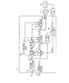
- FIG. 3 is a diagram illustrating an example of a functional block diagram of the transmission controller.
- FIG. 4 is a diagram illustrating an example of a Bode diagram of the phase advance compensator.
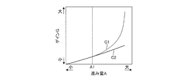
- FIG. 5 is a diagram illustrating an example of a gain change of the phase lead compensator.
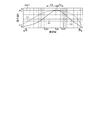
- FIG. 6 is an explanatory diagram of the influence of the frequency shift.
- FIG. 7 is a flowchart illustrating an example of control performed by the transmission controller.
- FIG. 1 is a schematic configuration diagram of a vehicle including a transmission controller 12.
- the vehicle includes an engine 1 as a power source.
- the power of the engine 1 is transmitted to the drive wheels 7 via the torque converter 2, the first gear train 3, the transmission 4, the second gear train 5, and the differential 6 that constitute the power train PT.
- the second gear train 5 is provided with a parking mechanism 8 that mechanically locks the output shaft of the transmission 4 during parking.
- the torque converter 2 includes a lock-up clutch 2a.
- the lock-up clutch 2a When the lock-up clutch 2a is engaged, slippage in the torque converter 2 is eliminated, and the transmission efficiency of the torque converter 2 is improved.
- the lock-up clutch 2a is referred to as the LU clutch 2a.
- the transmission 4 is a continuously variable transmission including a variator 20.
- the variator 20 is a continuously variable transmission mechanism that includes a pulley 21 that is a primary pulley, a pulley 22 that is a secondary pulley, and a belt 23 that is wound around the pulleys 21 and 22.
- the pulley 21 constitutes a driving side rotating element
- the pulley 22 constitutes a driven side rotating element.
- Each of the pulleys 21 and 22 includes a fixed conical plate, a movable conical plate that is disposed with a sheave surface facing the fixed conical plate, and forms a V-groove between the fixed conical plate, and a rear surface of the movable conical plate. And a hydraulic cylinder that displaces the movable conical plate in the axial direction.
- the pulley 21 includes a hydraulic cylinder 23a as a hydraulic cylinder
- the pulley 22 includes a hydraulic cylinder 23b as a hydraulic cylinder.
- the variator 20 may be a toroidal continuously variable transmission mechanism.
- the transmission 4 further includes an auxiliary transmission mechanism 30.
- the subtransmission mechanism 30 is a transmission mechanism having two forward speeds and one reverse speed, and has a first speed and a second speed having a smaller gear ratio than the first speed.
- the auxiliary transmission mechanism 30 is provided in series with the variator 20 in the power transmission path from the engine 1 to the drive wheels 7.
- the sub-transmission mechanism 30 may be directly connected to the output shaft of the variator 20 as in this example, or may be connected via another power transmission mechanism such as a shift or a gear train. Alternatively, the auxiliary transmission mechanism 30 may be connected to the input shaft side of the variator 20.
- the vehicle further includes an oil pump 10 that is driven using a part of the power of the engine 1, and a hydraulic control circuit that adjusts the hydraulic pressure generated by the oil pump 10 by supplying oil and supplies the hydraulic pressure to each part of the transmission 4. 11 and a transmission controller 12 that controls the hydraulic control circuit 11 are provided.
- the hydraulic control circuit 11 includes a plurality of flow paths and a plurality of hydraulic control valves.
- the hydraulic control circuit 11 switches a hydraulic pressure supply path by controlling a plurality of hydraulic control valves based on a shift control signal from the transmission controller 12.
- the hydraulic control circuit 11 adjusts the required hydraulic pressure from the hydraulic pressure generated by the oil pump 10 by supplying oil, and supplies the adjusted hydraulic pressure to each part of the transmission 4. As a result, the variator 20 is shifted, the sub-transmission mechanism 30 is changed, and the LU clutch 2a is engaged / released.
- FIG. 2 is a schematic configuration diagram of the transmission controller 12.
- the transmission controller 12 includes a CPU 121, a storage device 122 including a RAM / ROM, an input interface 123, an output interface 124, and a bus 125 that connects these components to each other.
- the input interface 123 includes, for example, an output signal of an accelerator opening sensor 41 that detects an accelerator opening APO that represents an operation amount of an accelerator pedal, an output signal of a rotational speed sensor 42 that detects an input side rotational speed of the transmission 4, and a pulley.
- the output signal of the rotation speed sensor 43 for detecting the rotation speed Nsec of 22 and the output signal of the rotation speed sensor 44 for detecting the output side rotation speed of the transmission 4 are input.
- the input side rotational speed of the transmission 4 is the rotational speed of the input shaft of the transmission 4, and hence the rotational speed Npri of the pulley 21.
- the output side rotational speed of the transmission 4 is the rotational speed of the output shaft of the transmission 4, and hence the rotational speed of the output shaft of the subtransmission mechanism 30.
- the input side rotational speed of the transmission 4 may be a rotational speed at a position where a gear train or the like is sandwiched between the transmission 4 and the like, for example, a turbine rotational speed of the torque converter 2. The same applies to the output side rotational speed of the transmission 4.
- the input interface 123 further includes an output signal of the vehicle speed sensor 45 that detects the vehicle speed VSP, an output signal of the oil temperature sensor 46 that detects the oil temperature TMP of the transmission 4, and an output signal of the inhibitor switch 47 that detects the position of the select lever.
- An output signal of the hydraulic sensor 50 that detects the above is input.
- a torque signal of the engine torque Te is also input to the input interface 123 from the engine controller 51 provided in the engine 1.
- the storage device 122 stores a shift control program for the transmission 4, various maps used in the shift control program, and the like.
- the CPU 121 reads and executes the shift control program stored in the storage device 122 and generates a shift control signal based on various signals input via the input interface 123. Further, the CPU 121 outputs the generated shift control signal to the hydraulic control circuit 11 via the output interface 124.
- Various values used by the CPU 121 in the calculation process and the calculation results of the CPU 121 are stored in the storage device 122 as appropriate.
- longitudinal vibration may occur at the PT resonance frequency Fpt, which is the resonance frequency of the power train PT. It is considered that the longitudinal vibration is generated by coupling the torque fluctuation and the shift of the transmission 4 when the stability of the transmission ratio of the transmission 4 is insufficient with respect to the torque fluctuation of the power train PT. For this reason, it is conceivable to suppress the longitudinal vibration by increasing the stability of the speed ratio of the transmission 4 by lead compensation.
- the controller 12 performs shift control as described below.
- the speed ratio of the variator 20 is used as the speed ratio of the transmission 4.
- the gear ratio Ratio is a general term for the gear ratios of the variator 20 including an actual gear ratio Ratio_A, a target gear ratio Ratio_D, and a final gear ratio Ratio_T, which will be described later, and includes at least one of them.
- the transmission ratio of the transmission 4 may be a through transmission ratio that is the transmission ratio of the variator 20 and the auxiliary transmission mechanism 30 as a whole.
- the transmission controller 12 is simply referred to as a controller 12.
- FIG. 3 is a diagram showing an example of a functional block diagram of the controller 12 showing a main part of the shift control.
- the controller 12 includes a target value generation unit 131, an FB compensator 132, a lead compensation on / off determination unit 133, a lead amount determination unit 134, a lead amount filter unit 135, and a first phase lead that is a first lead compensation unit.
- the compensator 136 includes a second phase lead compensator 137 that is a second lead compensation unit, a switch unit 138, an on / off command filter unit 139, a sensor value filter unit 140, and a peak value frequency determination unit 141.
- FB is an abbreviation for feedback.
- the target value generation unit 131 generates a target value for shift control.
- the target value is a target speed ratio Ratio_D based on a final speed ratio Ratio_T that is a final target speed control value with the speed ratio Ratio as a speed control value.
- the shift control value may be, for example, the primary pressure Ppri as a control parameter.
- the ultimate transmission ratio Ratio_T is preset according to the driving state of the vehicle in the shift map. For this reason, the target value generation unit 131 reads the corresponding reaching speed ratio Ratio_T from the shift map based on the detected driving state.
- the driving state of the vehicle is a vehicle speed VSP and an accelerator opening APO.
- the target value generation unit 131 calculates the target speed ratio Ratio_D based on the reached speed ratio Ratio_T.
- the target speed ratio Ratio_D is a transitional target speed ratio until the target speed ratio Ratio_T is reached, and constitutes a target speed control value.
- the calculated target gear ratio Ratio_D is input to the FB compensator 132.
- the FB compensator 132 calculates a feedback command value based on the actual speed ratio Ratio_A and the target speed ratio Ratio_D, which are actual values of the speed ratio Ratio.
- the feedback command value is, for example, a feedback primary command pressure Ppri_FB for filling an error between the actual speed ratio Ratio_A and the target speed ratio Ratio_D.
- the calculated feedback command value (feedback primary command pressure Ppri_FB) is input to the advance amount determination unit 134 and the first phase advance compensator 136.
- the advance compensation on / off determination unit 133 determines on / off of the phase advance compensation of the feedback primary command pressure Ppri_FB, that is, execution / stop of the phase advance compensation.
- Lead compensation on / off determination section 133 determines on / off of phase lead compensation according to pulley state value M.
- the pulley state value M is a value for determining whether or not the pulleys 21 and 22 are in a state in which longitudinal vibration occurs, and the rotational speed Npri, the input torque Tsec to the pulley 22, the transmission ratio Ratio, It includes the rate of change ⁇ of the ratio Ratio.
- the input torque Tsec is calculated as a value obtained by multiplying the engine torque Te by the gear ratio set between the engine 1 and the pulley 22, and thus in the present embodiment, the gear ratio of the first gear train 3 and the gear ratio of the variator 20. Can do.
- the actual speed ratio Ratio_A and the target speed ratio Ratio_D can be applied to the speed ratio Ratio.
- the speed ratio Ratio may be the actual speed ratio Ratio_A or the target speed ratio Ratio_D.
- the advance compensation on / off determination unit 133 further determines the phase of the feedback primary command pressure Ppri_FB according to the engaged state of the LU clutch 2a, the state of the driver operation on the transmission 4, and the presence or absence of a failure Determine on / off of lead compensation.
- the method for determining the on / off of the phase lead compensation performed by the lead compensation on / off determination unit 133 will be specifically described later with reference to a flowchart.
- the lead compensation on / off determination unit 133 outputs an on command when it is determined that phase lead compensation is on, and outputs an off command when it is determined that phase lead compensation is off.
- the on command and the off command are collectively referred to as an on / off command.
- the on / off command is input from the advance compensation on / off determination unit 133 to the advance amount determination unit 134 and the on / off command filter unit 139.
- the advance amount determination unit 134 determines an advance amount A for phase advance compensation of the feedback primary command pressure Ppri_FB.
- the advance amount determination unit 134 determines the advance amount Apk according to the on / off command.
- the advance amount determination unit 134 determines the advance amount Apk to be zero when an off command is input.
- the advance amount determination unit 134 determines the advance amount Apk as the first advance amount Apk1 or the second advance amount Apk2 when an ON command is input.
- the first advance amount Apk1 is set in correspondence with the case of performing first-order phase lead compensation described later, and the second advance amount Apk2 is set in correspondence with the case of performing second-order phase lead compensation described later. .
- the second advance amount Apk2 is set to 1 ⁇ 2 of the first advance amount Apk1.
- the first advance amount Apk1 is, for example, 80 deg and can be a constant value.
- the first advance amount Apk1 can be set in advance by experiments or the like.
- the advance amount Apk is input from the advance amount determination unit 134 to the advance amount filter unit 135.
- the advance amount filter unit 135 performs a filter process of the advance amount Apk.
- the advance amount filter unit 135 may be omitted.
- the advance amount Apk is input from the advance amount filter unit 135 to the first phase advance compensator 136, the second phase advance compensator 137, and the switch unit 138.
- the peak value frequency Fpk from the peak value frequency determining unit 141 is also input to the first phase lead compensator 136 and the second phase lead compensator 137.
- the peak value frequency Fpk is a frequency set according to the target frequency in the phase lead compensation. Specifically, the target frequency is the PT resonance frequency Fpt. For this reason, the peak value frequency Fpk is set to, for example, the PT resonance frequency Fpt.
- the peak value frequency Fpk is 2 Hz, for example, and is a fixed value, that is, fixed.
- the PT resonance frequency Fpt set as the target frequency to the peak value frequency Fpk does not necessarily match the actual PT resonance frequency Fpt.
- Both the first phase advance compensator 136 and the second phase advance compensator 137 are based on the input advance amount Apk and the input peak value frequency Fpk, and the primary phase advance compensation of the feedback primary command pressure Ppri_FB. I do.
- the phase advance compensation of the feedback primary command pressure Ppri_FB By performing the phase advance compensation of the feedback primary command pressure Ppri_FB, the phase advance compensation of the feedback shift control of the transmission 4 is performed.
- the first phase lead compensator 136 and the second phase lead compensator 137 are composed of a first-order low-pass filter, and correspond to the inputted advance amount Apk and further the inputted peak value frequency Fpk. By performing the filtering process, the primary phase lead compensation of the feedback primary command pressure Ppri_FB is performed.
- the second phase lead compensator 137 is provided in series with the first phase lead compensator 136.
- the feedback primary command pressure Ppri_FB subjected to the first-order phase advance compensation by the first phase advance compensator 136 is input to the second phase advance compensator 137.
- the second phase lead compensator 137 further performs the primary phase lead compensation when performing the primary phase lead compensation of the feedback primary command pressure Ppri_FB. Thereby, the secondary phase lead compensation of the feedback primary command pressure Ppri_FB is performed.
- the switch unit 138 performs the phase lead compensation by the first phase lead compensator 136 and the second phase lead compensator 137 in accordance with the input lead amount Apk, that is, the case where the second phase lead compensation is performed.
- the phase lead compensation is performed only by the first phase lead compensator 136, that is, when the first phase lead compensation is performed.
- FIG. 4 is a diagram showing an example of a Bode diagram of the phase lead compensator.
- FIG. 5 is a diagram illustrating an example of a gain change at a predetermined frequency of the phase lead compensator.
- the horizontal axis indicates the frequency logarithmically.
- the thin line C1 shows the case of the primary phase lead compensator, and the thick line C2 shows the case of the secondary phase lead compensator.
- the phase advance compensator is set so that the advance amount A becomes the first advance amount Apk1 at the peak value frequency Fpk.
- the first phase lead compensator 136 and the second phase lead compensator 137 when performing the second-order phase lead compensation, the first phase lead compensator 136 and the second phase lead compensator 137, respectively.
- the advance amount A corresponding to the peak value frequency Fpk is set as the first advance amount Apk1.
- the gain G increases as the advance amount A increases in both the primary and secondary cases.
- the increase rate of the secondary gain G becomes smaller than the increase rate of the primary gain G as the advance amount A increases. That is, the gain suppression effect by the quadratic phase advance compensation is obtained when the advance amount A is larger than the predetermined value A1.
- the advance amount A when the advance amount A is smaller than the predetermined value A1, the gain suppression effect cannot be obtained due to the quadratic phase advance compensation, but the advance amount A greatly decreases on both sides of the peak value frequency Fpk. The effect of doing will occur. As a result, the advance amount A tends to decrease due to the frequency shift between the actual PT resonance frequency Fpt and the peak value frequency Fpk, and the effect of improving the stability of the transmission ratio Ratio, that is, the vibration damping effect is likely to decrease.
- the predetermined value A1 can be set in advance based on the change characteristic of the gain G according to the advance amount A as shown in FIG.
- the predetermined value A1 can be preferably set to a minimum value within a range in which a gain suppression effect by the quadratic phase advance compensation can be obtained.
- the lead amount determination unit 134 and the switch unit 138 shown in FIG. 3 are specifically configured as follows.
- the advance amount determination unit 134 calculates the advance amount A of the primary phase advance compensation of the feedback primary command pressure Ppri_FB based on the input feedback primary command pressure Ppri_FB. Then, the advance amount determination unit 134 determines that the primary phase advance compensation is performed when the advance amount A is smaller than the predetermined value A1, and determines the advance amount Apk as the first advance amount Apk1. Further, the advance amount determination unit 134 determines that the secondary phase advance compensation is performed when the advance amount A is equal to or greater than the predetermined value A1, and determines the advance amount Apk as the second advance amount Apk2.
- the advance amount A can be set in advance using map data or the like.
- the switch unit 138 performs switching so that the phase advance compensation is performed only by the first phase advance compensator 136 when the first advance amount Apk1 is input. In addition, when the second advance amount Apk2 is input, the switch unit 138 performs switching so that the first phase advance compensator 136 and the second phase advance compensator 137 perform phase advance compensation.
- the first phase lead compensator 136 and the second phase lead compensator 137 are configured to perform phase lead compensation only with the first phase lead compensator 136 according to the lead amount A. .
- the first phase lead compensator 136 and the second phase lead compensator 137 are configured to perform phase lead compensation only with the first phase lead compensator 136 when the lead amount A is smaller than the predetermined value A1.
- the first phase lead compensator 136 and the second phase lead compensator 137 are arranged so that the first phase lead compensator 136 and the second phase lead compensator 137 perform the phase lead compensation when the lead amount A is equal to or greater than the predetermined value A1. Configured to do.
- the advance amount determination unit 134 may input the advance amount A to the switch unit 138 instead of the advance amount Apk, and the switch unit 138 may perform switching based on the input advance amount A in this way. .
- the actuator 111 receives a primary command pressure Ppri_FF (a target primary command pressure that determines a balance thrust and a gear ratio) that is set based on a feedback primary command pressure Ppri_FB selected from the switch unit 138 and a target gear ratio Ratio_D. Is done.
- the actuator 111 is, for example, a primary pressure control valve that controls the primary pressure Ppri provided in the hydraulic pressure control circuit 11, and the primary pressure so that the actual pressure Ppri_A of the primary pressure Ppri becomes the command pressure Ppri_D corresponding to the target gear ratio Ratio_D. Control Ppri.
- the transmission gear ratio Ratio is controlled so that the actual transmission gear ratio Ratio_A becomes the target transmission gear ratio Ratio_D.
- the sensor unit 40 detects the actual gear ratio Ratio_A of the variator 20.
- the sensor unit 40 includes a rotation speed sensor 42 and a rotation speed sensor 43.
- the actual speed ratio Ratio_A that is the actual speed ratio (sensor value) detected by the sensor unit 40 is input to the sensor value filter unit 140.
- An on / off command is also input to the sensor value filter unit 140 via an on / off command filter unit 139 that performs on / off command filter processing.
- the on / off command filter unit 139 may be omitted.
- the sensor value filter unit 140 performs a filter process of the actual gear ratio Ratio_A.
- the sensor value filter unit 140 switches the order of the filter processing or execution / stop according to the on / off command.
- the sensor value filter unit 140 is a primary low-pass filter when an off command is input, and is a high-order low-pass filter when an on command is input, or stops the filter process.
- the sensor value filter unit 140 may be configured to include one or a plurality of first-order low-pass filters provided so that execution / stop of the filter processing or the order can be switched.
- the actual speed ratio Ratio_A filtered by the sensor value filter unit 140 or the actual speed ratio Ratio_A as it is is input to the FB compensator 132.
- the peak value frequency determining unit 141 determines the peak value frequency Fpk for phase advance compensation.
- the peak value frequency determination unit 141 determines the peak value frequency Fpk for phase advance compensation in accordance with the gear ratio Ratio. Specifically, when the advance amount Apk1 is input, that is, when the primary phase advance compensation is performed, the peak value frequency Fpk is set to the PT resonance frequency Fpt determined based on the speed ratio Ratio.
- the PT resonance frequency Fpt set as the target frequency to the peak value frequency Fpk does not necessarily match the actual PT resonance frequency Fpt.
- the second-order phase advance compensation is performed, a situation in which the advance amount A decreases as described below due to a frequency shift between the actual PT resonance frequency Fpt and the peak value frequency Fpk occurs.
- FIG. 6 is an explanatory diagram of the influence of the shift of the peak value frequency Fpk.
- the horizontal axis indicates the frequency logarithmically.
- the PT resonance frequency Fpt1 indicates a case where the actual PT resonance frequency Fpt is lower than the peak value frequency Fpk
- the PT resonance frequency Fpt2 indicates a case where the actual PT resonance frequency Fpt is higher than the peak value frequency Fpk. Between these, the magnitude FA of the frequency deviation is the same.
- the PT resonance frequency Fpt2 is the case where the actual PT resonance frequency Fpt is the PT resonance frequency Fpt1 even if the magnitude FA is the same.
- the amount of decrease in the advance amount A is larger than that in the case where it is the case.
- the peak value frequency determination unit 141 receives the peak value frequency Fpk when the second advance amount Apk2 is input, that is, when the second-order phase advance compensation is performed, than when the first-order phase advance compensation is performed. By making it low, the advance amount A is not greatly reduced in a biased manner depending on the direction of frequency shift.
- step S1 to step S5 is processing for determining whether or not resonance of the power train PT occurs, in other words, processing for determining whether longitudinal vibration of the transmission 4 occurs.
- the resonance of the power train PT is referred to as PT resonance.
- step S1 the controller 12 determines whether or not the pulley state value M is a value at which longitudinal vibration occurs. That is, in step S1, it is determined whether the state of the pulleys 21 and 22 is a state in which longitudinal vibration occurs. Specifically, in step S1, the controller 12 performs the following determination for each of the rotational speed Npri, the input torque Tsec, the transmission ratio Ratio, and the change ratio ⁇ of the transmission ratio Ratio, which is the pulley state value M.
- the controller 12 determines whether or not the operating point corresponding to the rotational speed Npri and the input torque Tsec is in a determination region defined accordingly.
- the controller 12 determines that both the rotational speed Npri and the input torque Tsec are longitudinal vibration occurrence values. If the operating point is in the determination region, in other words, it is a state where the pulleys 21 and 22 are vulnerable to disturbance, that is, the stability of the transmission ratio Ratio is insufficient.
- the determination area can be set in advance by experiments or the like.
- the controller 12 determines that the speed ratio Ratio is a longitudinal vibration occurrence value when the speed ratio Ratio is greater than the predetermined speed ratio Ratio1, in other words, when the speed ratio Ratio is Low than the predetermined speed ratio Ratio1.
- the predetermined gear ratio Ratio1 is a value for defining a gear ratio at which longitudinal vibration occurs, and is 1, for example.
- the predetermined gear ratio Ratio1 can be set in advance by experiments or the like.
- the controller 12 determines that the change rate ⁇ is the longitudinal vibration occurrence value when the change rate ⁇ of the transmission ratio Ratio is smaller than the predetermined value ⁇ 1.
- the predetermined value ⁇ 1 is a value for defining the rate of change ⁇ at which the longitudinal vibration occurs. When the rate of change ⁇ is smaller than the predetermined value ⁇ 1, the speed ratio Ratio is in a steady state.
- the predetermined value ⁇ 1 can be set in advance through experiments or the like.
- step S1 the controller 12 makes an affirmative determination when it is determined that all of these pulley state values M are longitudinal vibration occurrence values, and if any of these pulley state values M is not a longitudinal vibration occurrence value. Make a negative decision.
- step S1 determines that PT resonance does not occur. Therefore, it is determined that no longitudinal vibration occurs. In this case, the process proceeds to step S10, and the controller 12 turns off the phase advance compensation. After step S10, the process of this flowchart ends.
- step S1 determines whether or not the LU clutch 2a is engaged. Thus, on / off of the phase lead compensation is determined according to the engaged state of the LU clutch 2a.
- step S2 If a negative determination is made in step S2, it is determined that no longitudinal vibration occurs because the LU clutch 2a is not engaged. In this case, the process proceeds to step S5. If an affirmative determination is made in step S2, it is determined that the state of the LU clutch 2a is a state in which longitudinal vibration occurs. In this case, the process proceeds to step S3.
- step S3 the controller 12 determines whether or not the state of the driver operation on the transmission 4 is a predetermined state.
- the predetermined state includes at least one of a first operation state in which the gear ratio Ratio is greater than the predetermined gear ratio Ratio1 and a second operation state in which the gear ratio Ratio is in a steady state.
- the first operation state is, for example, a state where the OD switch 49 is OFF.
- the second operation state is a state in which the gear ratio Ratio is fixed by a driver operation, such as a state in which a manual range is selected by the select lever or a state in which a manual mode such as a sports mode is selected.
- the gear ratio Ratio is continuously larger than the predetermined gear ratio Ratio1 or that the gear ratio Ratio is continuously in a steady state. can do. Therefore, it is possible to more reliably determine that the gear ratio Ratio is a state in which longitudinal vibration occurs.
- step S3 If the determination in step S3 is negative, it is determined that the longitudinal vibration does not occur because the driver operation state is not a predetermined state. In this case, the process proceeds to step S5. If the determination is affirmative in step S3, the process proceeds to step S4.
- step S4 the controller 12 determines that PT resonance occurs. Therefore, it is determined that longitudinal vibration occurs. After step S4, the process proceeds to step S6.
- step S8 it is determined whether or not phase lead compensation can be turned on. In other words, it is determined whether or not the phase lead compensation can be executed.
- the controller 12 determines whether or not there is a failure.
- the failure can be, for example, a failure for the transmission 4 including a failure of the hydraulic control circuit 11 and sensors / switches used for the transmission control of the transmission 4.
- the failure may be a vehicle failure including a failure for the transmission 4.
- step S6 determines whether the determination in step S6 is affirmative. If the determination in step S6 is affirmative, the process proceeds to step S8, and the controller 12 determines that the phase advance compensation should not be turned on. That is, the execution prohibition determination of the phase advance compensation is made. After step S8, the process proceeds to step S10.
- step S7 the process proceeds to step S7, and the controller 12 determines that the phase advance compensation may be turned on. In other words, the execution permission determination for phase advance compensation is made. In this case, the process proceeds to step S9, and the controller 12 turns on phase advance compensation. After step S9, the process of this flowchart ends.
- the lead compensation on / off determination unit 133 together with the switch unit 138, according to the pulley state value M, a feedback primary instruction in which lead compensation has been performed by at least one of the first phase lead compensator 136 and the second phase lead compensator 137.
- a setting unit that sets the pressure Ppri_FB as the feedback primary command pressure Ppri_FB is configured.
- At least one of the first phase lead compensator 136 and the second phase lead compensator 137 constitutes a lead compensation unit that performs lead compensation of the feedback primary command pressure Ppri_FB.
- the feedback primary command pressure Ppri_FB subjected to the advance compensation constitutes the compensated feedback primary command pressure Ppri_FB.
- the controller 12 constitutes a control device for a continuously variable transmission that performs feedback shift control of the transmission 4 such that the actual gear ratio Ratio_A becomes the target gear ratio Ratio_D.
- the controller 12 is provided in series with a first phase lead compensator 136 that performs primary phase lead compensation of the feedback primary command pressure Ppri_FB, and a first phase lead compensator 136, and the primary phase of the feedback primary command pressure Ppri_FB.
- a second phase lead compensator 137 that performs lead compensation.
- the secondary phase lead compensation can be simply performed by the two primary phase lead compensations. Further, by performing the secondary phase lead compensation, the gain G can be made lower than in the case of performing the primary phase lead compensation. For this reason, the longitudinal vibration of the transmission 4 can be improved while ensuring the stability of the shift control.
- the first phase lead compensator 136 and the second phase lead compensator 137 are configured to perform phase lead compensation only by the first phase lead compensator 136 according to the lead amount A. According to the controller 12 having such a configuration, when the secondary phase lead compensation is performed depending on the lead amount A, not only the gain G suppressing effect can be obtained, but also between the actual PT resonance frequency Fpt and the peak value frequency Fpk. It is possible to improve the situation in which the damping effect is impaired due to the frequency deviation.
- the first phase lead compensator 136 and the second phase lead compensator 137 perform the phase lead compensation only by the first phase lead compensator 136 when the lead amount A is smaller than the predetermined value A1. Composed. According to the controller 12 having such a configuration, the above-described situation can be appropriately improved.
- the controller 12 lowers the peak value frequency Fpk when performing the secondary phase lead compensation than when performing the primary phase lead compensation. According to the controller 12 having such a configuration, when the second-order phase lead compensation is performed, the lead amount A can be prevented from being greatly reduced in a biased manner depending on the shift direction of the frequency shift. For this reason, when performing the second-order phase lead compensation, it is possible to prevent the vibration suppression effect from being greatly impaired by the frequency shift.
- the advance compensation on / off determination unit 133 performs the on / off of the phase advance compensation of the feedback primary command pressure Ppri_FB according to all four parameters of the rotational speed Npri, the input torque Tsec, the speed ratio Ratio, and the change rate ⁇ . The case of determining is described.
- the advance compensation on / off determination unit 133 may be configured to determine on / off of the phase advance compensation according to at least one of the parameters of the input torque Tsec, the gear ratio Ratio, and the change rate ⁇ . Even in this case, the longitudinal vibration can be improved by appropriately increasing the shift stability of the transmission 4 in relation to the parameter.
- the controller 12 is configured to perform the phase advance compensation only by the first phase advance compensator 136 when the advance amount A is smaller than the predetermined value A1 has been described.
- the controller 12 may be configured to perform the first-order phase lead compensation only with the second phase lead compensator 137.
- the FB compensator 132 that performs feedback control of the servo system that performs feedback control based on the target speed ratio Ratio_D and the actual speed ratio Ratio_A has been described.
- the configuration is not limited to the feedback control of the servo system, and for example, an FB compensator that performs the feedback control according to the fluctuation of the input torque may be used.
- the controller 12 is configured as a control device for a continuously variable transmission.
- the control device for the continuously variable transmission may be realized by a plurality of controllers, for example.
Landscapes
- Engineering & Computer Science (AREA)
- General Engineering & Computer Science (AREA)
- Mechanical Engineering (AREA)
- Control Of Transmission Device (AREA)
Abstract
本発明は、実変速比が目標変速比になるように変速機(20)のフィードバック変速制御を行うコントローラ(12)を備える。該コントローラ(12)は、フィードバックプライマリ指示圧の1次の進み補償を行う第1位相進み補償器(136)と、第1位相進み補償器(136)と直列に設けられ、フィードバックプライマリ指示圧の1次の進み補償を行う第2位相進み補償器(137)と、を有する。
Description
本発明は、無段変速機の制御装置及び無段変速機の制御方法に関する。
無段変速機の変速制御に関し、JP2002-106700Aでは目標変速比に対する実変速比の応答遅れ分だけ目標変速比を進み補償する技術が開示されている。
無段変速機では、パワートレインの共振周波数で前後方向の揺さぶりを引き起こす前後振動が発生することがある。前後振動は、パワートレインのトルク変動に対して無段変速機の変速比の安定性が不足している場合に、トルク変動と無段変速機の変速とが連成して発生すると考えられる。このため、進み補償によって無段変速機の変速比の安定性を高めることで、前後振動を抑制することが考えられる。
ところがこの場合、進み補償のゲインが高いと変速制御が不安定になる結果、無段変速機を搭載する車両の挙動に影響が及ぶ虞がある。
本発明はこのような課題に鑑みてなされたもので、変速制御の安定性を確保しつつ無段変速機の前後振動を改善することが可能な無段変速機の制御装置及び無段変速機の制御方法を提供することを目的とする。
本発明のある態様の無段変速機の制御装置は、無段変速機の状態を現す実値に基づいてフィードバック制御を行う無段変速機の制御装置であって、前記フィードバック制御の1次の進み補償を行う第1進み補償部と、前記第1進み補償部と直列に設けられ、前記フィードバック変速制御の1次の進み補償を行う第2進み補償部と、を有する。
本発明の別の態様によれば、無段変速機の状態を現す実値に基づいてフィードバック制御を行う無段変速機の制御方法であって、前記フィードバック制御の1次の進み補償を行うことと、前記フィードバック制御の1次の進み補償をさらに重ねて行うこと、を含む無段変速機の制御方法が提供される。
これらの態様によれば、2つの1次の進み補償によって2次の進み補償をシンプルに行うことができる。また、2次の進み補償を行うことで、1次の進み補償を行う場合よりも、ゲインを低くすることができる。このため、変速制御の安定性を確保しつつ無段変速機の前後振動を改善することができる。
以下、添付図面を参照しながら本発明の実施形態について説明する。
図1は、変速機コントローラ12を含む車両の概略構成図である。車両は動力源としてエンジン1を備える。エンジン1の動力は、パワートレインPTを構成するトルクコンバータ2、第1ギヤ列3、変速機4、第2ギヤ列5及び差動装置6を介して、駆動輪7へと伝達される。第2ギヤ列5には駐車時に変速機4の出力軸を機械的に回転不能にロックするパーキング機構8が設けられる。
トルクコンバータ2は、ロックアップクラッチ2aを備える。ロックアップクラッチ2aが締結されると、トルクコンバータ2における滑りがなくなり、トルクコンバータ2の伝達効率が向上する。以下では、ロックアップクラッチ2aをLUクラッチ2aと称す。
変速機4は、バリエータ20を備える無段変速機である。バリエータ20は、プライマリプーリであるプーリ21と、セカンダリプーリであるプーリ22と、プーリ21、22の間に掛け回されるベルト23とを備える無段変速機構である。プーリ21は主動側回転要素を構成し、プーリ22は従動側回転要素を構成する。
プーリ21、22それぞれは、固定円錐板と、固定円錐板に対してシーブ面を対向させた状態で配置され固定円錐板との間にV溝を形成する可動円錐板と、可動円錐板の背面に設けられて可動円錐板を軸方向に変位させる油圧シリンダとを備える。プーリ21は油圧シリンダとして油圧シリンダ23aを備え、プーリ22は油圧シリンダとして油圧シリンダ23bを備える。
油圧シリンダ23a、23bに供給される油圧を調整すると、V溝の幅が変化してベルト23と各プーリ21、22との接触半径が変化し、バリエータ20の変速比が無段階に変化する。バリエータ20は、トロイダル型の無段変速機構であってもよい。
変速機4は、副変速機構30をさらに備える。副変速機構30は、前進2段・後進1段の変速機構であり、前進用変速段として、1速と、1速よりも変速比の小さな2速を有する。副変速機構30は、エンジン1から駆動輪7に至るまでの動力伝達経路において、バリエータ20と直列に設けられる。
副変速機構30は、この例のようにバリエータ20の出力軸に直接接続されていてもよいし、その他の変速ないしギヤ列等の動力伝達機構を介して接続されていてもよい。あるいは、副変速機構30はバリエータ20の入力軸側に接続されていてもよい。
車両にはさらに、エンジン1の動力の一部を利用して駆動されるオイルポンプ10と、オイルポンプ10がオイル供給によって発生させる油圧を調整して変速機4の各部位に供給する油圧制御回路11と、油圧制御回路11を制御する変速機コントローラ12とが設けられる。
油圧制御回路11は複数の流路、複数の油圧制御弁で構成される。油圧制御回路11は、変速機コントローラ12からの変速制御信号に基づき、複数の油圧制御弁を制御して油圧供給経路を切り換える。また、油圧制御回路11は、オイルポンプ10がオイル供給によって発生させる油圧から必要な油圧を調整し、調整した油圧を変速機4の各部位に供給する。これにより、バリエータ20の変速、副変速機構30の変速段の変更、LUクラッチ2aの締結・解放が行われる。
図2は、変速機コントローラ12の概略構成図である。変速機コントローラ12は、CPU121と、RAM・ROMからなる記憶装置122と、入力インターフェース123と、出力インターフェース124と、これらを相互に接続するバス125とを有して構成される。
入力インターフェース123には例えば、アクセルペダルの操作量を表すアクセル開度APOを検出するアクセル開度センサ41の出力信号、変速機4の入力側回転速度を検出する回転速度センサ42の出力信号、プーリ22の回転速度Nsecを検出する回転速度センサ43の出力信号、変速機4の出力側回転速度を検出する回転速度センサ44の出力信号が入力される。
変速機4の入力側回転速度は具体的には、変速機4の入力軸の回転速度、したがってプーリ21の回転速度Npriである。変速機4の出力側回転速度は具体的には、変速機4の出力軸の回転速度、したがって副変速機構30の出力軸の回転速度である。変速機4の入力側回転速度は、例えばトルクコンバータ2のタービン回転速度など、変速機4との間にギヤ列等を挟んだ位置の回転速度であってもよい。変速機4の出力側回転速度についても同様である。
入力インターフェース123にはさらに、車速VSPを検出する車速センサ45の出力信号、変速機4の油温TMPを検出する油温センサ46の出力信号、セレクトレバーの位置を検出するインヒビタスイッチ47の出力信号、エンジン1の回転速度Neを検出する回転速度センサ48の出力信号、変速機4の変速範囲を1よりも小さい変速比に拡大するためのODスイッチ49の出力信号、LUクラッチ2aへの供給油圧を検出する油圧センサ50の出力信号などが入力される。入力インターフェース123には、エンジン1が備えるエンジンコントローラ51から、エンジントルクTeのトルク信号も入力される。
記憶装置122には、変速機4の変速制御プログラム、変速制御プログラムで用いる各種マップ等が格納されている。CPU121は、記憶装置122に格納されている変速制御プログラムを読み出して実行し、入力インターフェース123を介して入力される各種信号に基づき変速制御信号を生成する。また、CPU121は、生成した変速制御信号を出力インターフェース124を介して油圧制御回路11に出力する。CPU121が演算処理で使用する各種値、CPU121の演算結果は記憶装置122に適宜格納される。
ところで、変速機4では、パワートレインPTの共振周波数であるPT共振周波数Fptで前後振動が発生することがある。前後振動は、パワートレインPTのトルク変動に対して、変速機4の変速比の安定性が不足している場合に、トルク変動と変速機4の変速とが連成して発生すると考えられる。このため、進み補償によって変速機4の変速比の安定性を高めることで、前後振動を抑制することが考えられる。
ところがこの場合、進み補償のゲインが高いと変速制御が不安定になる結果、変速機4を搭載する車両の挙動に影響が及ぶことが懸念される。
このため、コントローラ12は、以下で説明するように変速制御を行う。以下では、変速機4の変速比としてバリエータ20の変速比Ratioを用いて説明する。変速比Ratioは、後述する実変速比Ratio_A、目標変速比Ratio_D及び到達変速比Ratio_Tを含むバリエータ20の変速比の総称であり、これらのうち少なくともいずれかであることを含む。プーリ21への供給油圧であるプライマリ圧Ppriについても同様である。変速機4の変速比は、バリエータ20及び副変速機構30全体の変速比であるスルー変速比とされてもよい。以下では、変速機コントローラ12を単にコントローラ12と称す。
図3は、変速制御の要部を示すコントローラ12の機能ブロック図の一例を示す図である。コントローラ12は、目標値生成部131と、FB補償器132と、進み補償オンオフ決定部133と、進み量決定部134と、進み量フィルタ部135と、第1進み補償部である第1位相進み補償器136と、第2進み補償部である第2位相進み補償器137と、スイッチ部138と、オンオフ指令フィルタ部139と、センサ値フィルタ部140と、ピーク値周波数決定部141とを有する。FBはフィードバックの略である。
目標値生成部131は、変速制御の目標値を生成する。目標値は具体的には、変速比Ratioを変速制御値とした最終目標変速制御値である到達変速比Ratio_Tに基づく目標変速比Ratio_Dとされる。変速制御値は例えば、制御パラメータとしてのプライマリ圧Ppriとされてもよい。
到達変速比Ratio_Tは、変速マップで車両の運転状態に応じて予め設定されている。このため、目標値生成部131は、検出された運転状態に基づき、対応する到達変速比Ratio_Tを変速マップから読み出す。車両の運転状態は具体的には、車速VSP及びアクセル開度APOとされる。
目標値生成部131は、到達変速比Ratio_Tに基づき、目標変速比Ratio_Dを算出する。目標変速比Ratio_Dは、到達変速比Ratio_Tになるまでの間の過渡的な目標変速比であり、目標変速制御値を構成する。算出された目標変速比Ratio_Dは、FB補償器132に入力される。
FB補償器132は、変速比Ratioの実値である実変速比Ratio_A、目標変速比Ratio_Dに基づき、フィードバック指令値を算出する。フィードバック指令値は、例えば、実変速比Ratio_Aと目標変速比Ratio_Dの誤差を埋めるためのフィードバックプライマリ指示圧Ppri_FBである。算出されたフィードバック指令値(フィードバックプライマリ指示圧Ppri_FB)は、進み量決定部134と、第1位相進み補償器136に入力される。
進み補償オンオフ決定部133は、フィードバックプライマリ指示圧Ppri_FBの位相進み補償のオンオフ、つまり位相進み補償の実行・停止を決定する。進み補償オンオフ決定部133は、プーリ状態値Mに応じて、位相進み補償のオンオフを決定する。プーリ状態値Mは、プーリ21、22が、前後振動が発生する状態であるか否かを判定するための値であり、回転速度Npri、プーリ22への入力トルクTsec、変速比Ratio、及び変速比Ratioの変化率αを含む。
入力トルクTsecは例えば、エンジン1及びプーリ22間に設定された変速比、したがって本実施形態では第1ギヤ列3のギヤ比及びバリエータ20の変速比をエンジントルクTeに乗じた値として算出することができる。変速比Ratioには、実変速比Ratio_A及び目標変速比Ratio_Dを適用することができる。変速比Ratioは、実変速比Ratio_Aまたは目標変速比Ratio_Dとされてもよい。
進み補償オンオフ決定部133は、プーリ状態値Mに加えてさらに、LUクラッチ2aの締結状態と、変速機4に対するドライバ操作の状態と、フェールの有無とに応じて、フィードバックプライマリ指示圧Ppri_FBの位相進み補償のオンオフを決定する。進み補償オンオフ決定部133が行う位相進み補償のオンオフの決定方法については、具体的にはフローチャートを用いて後述する。
進み補償オンオフ決定部133は、位相進み補償のオンを決定した場合にはオン指令を出力し、位相進み補償のオフを決定した場合にはオフ指令を出力する。以下では、オン指令、オフ指令を総称する場合には、オンオフ指令と称す。オンオフ指令は、進み補償オンオフ決定部133から、進み量決定部134と、オンオフ指令フィルタ部139とに入力される。
進み量決定部134は、フィードバックプライマリ指示圧Ppri_FBを位相進み補償するための進み量Aを決定する。進み量決定部134は、オンオフ指令に応じて進み量Apkを決定する。進み量決定部134は、オフ指令が入力された場合に進み量Apkをゼロに決定する。進み量決定部134は、オン指令が入力された場合に進み量Apkを第1進み量Apk1又は第2進み量Apk2に決定する。
第1進み量Apk1は、後述する1次の位相進み補償を行う場合に対応させて設定され、第2進み量Apk2は、後述する2次の位相進み補償を行う場合に対応させて設定される。第2進み量Apk2は、第1進み量Apk1の1/2とされる。第1進み量Apk1は例えば、80degであり一定値とすることができる。第1進み量Apk1は、実験等により予め設定することができる。進み量Apkは、進み量決定部134から進み量フィルタ部135に入力される。
進み量フィルタ部135は、進み量Apkのフィルタ処理を行う。進み量フィルタ部135は、省略されてもよい。進み量フィルタ部135からは、第1位相進み補償器136と、第2位相進み補償器137と、スイッチ部138とに進み量Apkが入力される。
第1位相進み補償器136と第2位相進み補償器137とには、ピーク値周波数決定部141からピーク値周波数Fpkも入力される。ピーク値周波数Fpkは、位相進み補償で狙いの周波数に応じて設定される周波数である。狙いの周波数は具体的には、PT共振周波数Fptである。このため、ピーク値周波数Fpkは例えば、PT共振周波数Fptに設定される。ピーク値周波数Fpkは例えば、2Hzであり一定値、つまり固定とされる。但し、ピーク値周波数Fpkに狙いの周波数として設定されるPT共振周波数Fptは、実際のPT共振周波数Fptとは必ずしも一致しない。
第1位相進み補償器136と第2位相進み補償器137とはともに、入力された進み量Apk、さらには入力されたピーク値周波数Fpkに基づき、フィードバックプライマリ指示圧Ppri_FBの1次の位相進み補償を行う。フィードバックプライマリ指示圧Ppri_FBの位相進み補償を行うことで、変速機4のフィードバック変速制御の位相進み補償が行われる。第1位相進み補償器136と第2位相進み補償器137とは具体的には、1次のローパスフィルタで構成され、入力された進み量Apk、さらには入力されたピーク値周波数Fpkに応じたフィルタ処理を行うことで、フィードバックプライマリ指示圧Ppri_FBの1次の位相進み補償を行う。
第2位相進み補償器137は、第1位相進み補償器136と直列に設けられる。第2位相進み補償器137には、第1位相進み補償器136によって1次の位相進み補償が行われたフィードバックプライマリ指示圧Ppri_FBが入力される。
したがって、第2位相進み補償器137は、フィードバックプライマリ指示圧Ppri_FBの1次の位相進み補償を行う場合に、1次の位相進み補償をさらに重ねて行う。これにより、フィードバックプライマリ指示圧Ppri_FBの2次の位相進み補償が行われる。
スイッチ部138は、入力された進み量Apkに応じて、第1位相進み補償器136と第2位相進み補償器137とで位相進み補償を行う場合、つまり2次の位相進み補償を行う場合と、第1位相進み補償器136のみで位相進み補償を行う場合、つまり1次の位相進み補償を行う場合とを切り替える。
図4は、位相進み補償器のボード線図の一例を示す図である。図5は、位相進み補償器の所定周波数におけるゲイン変化の一例を示す図である。図4において、横軸は周波数を対数で示す。図4、図5において、細線C1は1次の位相進み補償器の場合を示し、太線C2は2次の位相進み補償器の場合を示す。1次、2次の場合ともに、位相進み補償器は、ピーク値周波数Fpkで進み量Aが第1進み量Apk1になるように設定されている。第1位相進み補償器136及び第2位相進み補償器137からなる位相進み補償器では、2次の位相進み補償を行う場合に、第1位相進み補償器136及び第2位相進み補償器137それぞれの進み量Apkを第2進み量Apk2とすることで、ピーク値周波数Fpkに応じた進み量Aが第1進み量Apk1とされる。
図5に示すように、ゲインGは、1次、2次の場合ともに、進み量Aが大きくなると大きくなる。但し、進み量Aが所定値A1を超えたあたりからは、進み量Aが大きくなるほど、1次のゲインGの上昇率に対して2次のゲインGの上昇率は小さくなる。つまり、位相進み補償の2次化によるゲイン抑制効果は、進み量Aが所定値A1よりも大きい場合に得られる。
図4に示すように、進み量Aが所定値A1より小さい場合、位相進み補償の2次化によって、ゲイン抑制効果が得られない一方で、ピーク値周波数Fpkの両側で進み量Aが大きく減少するという作用は生じることになる。結果、実際のPT共振周波数Fpt及びピーク値周波数Fpk間の周波数ずれによって進み量Aが減少し易くなり、変速比Ratioの安定性を向上させる効果、つまり制振効果が減少し易くなる。
このため、進み量Aが所定値A1よりも小さい場合には、1次の位相進み補償を行うことで、周波数ずれによって制振効果が減少し易くなる事態を避けることができる。所定値A1は、図5に示すような進み量Aに応じたゲインGの変化特性に基づき、予め設定することができる。所定値A1は、位相進み補償の2次化によるゲイン抑制効果が得られる範囲内で、好ましくは最小値に設定することができる。
このように位相進み補償を行うにあたり、図3に示す進み量決定部134とスイッチ部138とは具体的には次のように構成される。
すなわち、進み量決定部134は、入力されたフィードバックプライマリ指示圧Ppri_FBに基づきフィードバックプライマリ指示圧Ppri_FBの1次の位相進み補償の進み量Aを算出する。そして、進み量決定部134は、進み量Aが所定値A1よりも小さい場合に1次の位相進み補償を行うと判断し、進み量Apkを第1進み量Apk1に決定する。また、進み量決定部134は、進み量Aが所定値A1以上の場合に2次の位相進み補償を行うと判断し、進み量Apkを第2進み量Apk2に決定する。進み量Aは、マップデータ等で予め設定することができる。
スイッチ部138は、第1進み量Apk1が入力された場合に、第1位相進み補償器136のみで位相進み補償を行うように切り替えを行う。また、スイッチ部138は、第2進み量Apk2が入力された場合に、第1位相進み補償器136と第2位相進み補償器137とで位相進み補償を行うように切り替えを行う。
このように構成することで、第1位相進み補償器136及び第2位相進み補償器137は、進み量Aに応じて第1位相進み補償器136のみで位相進み補償を行うように構成される。また、第1位相進み補償器136及び第2位相進み補償器137は、進み量Aが所定値A1よりも小さい場合に、第1位相進み補償器136のみで位相進み補償を行うように構成される。また、第1位相進み補償器136及び第2位相進み補償器137は、進み量Aが所定値A1以上の場合に、第1位相進み補償器136及び第2位相進み補償器137で位相進み補償を行うように構成される。進み量決定部134は、進み量Apkの代わりに進み量Aをスイッチ部138に入力してもよく、スイッチ部138は、このようにして入力された進み量Aに基づき切り替えを行ってもよい。
アクチュエータ111には、スイッチ部138から選択されたフィードバックプライマリ指示圧Ppri_FBと目標変速比Ratio_Dに基づいて設定された図示しないプライマリ指示圧Ppri_FF(バランス推力や変速比を決定する目標プライマリ指示圧)が入力される。アクチュエータ111は例えば、油圧制御回路11に設けられたプライマリ圧Ppriを制御するプライマリ圧制御弁であり、プライマリ圧Ppriの実圧Ppri_Aが目標変速比Ratio_Dに応じた指示圧Ppri_Dになるようにプライマリ圧Ppriを制御する。これにより、実変速比Ratio_Aが目標変速比Ratio_Dになるように変速比Ratioが制御される。
センサ部40は、バリエータ20の実変速比Ratio_Aを検出する。センサ部40は具体的には、回転速度センサ42及び回転速度センサ43で構成されている。センサ部40が検出した変速比の実値(センサ値)である実変速比Ratio_Aは、センサ値フィルタ部140に入力される。センサ値フィルタ部140には、オンオフ指令のフィルタ処理を行うオンオフ指令フィルタ部139を介して、オンオフ指令も入力される。オンオフ指令フィルタ部139は省略されてもよい。
センサ値フィルタ部140は、実変速比Ratio_Aのフィルタ処理を行う。センサ値フィルタ部140は、オンオフ指令に応じて、フィルタ処理の次数又は実行・停止が切り替えられる。センサ値フィルタ部140は、オフ指令が入力された場合に1次のローパスフィルタとされ、オン指令が入力された場合に高次のローパスフィルタとされるか、或いはフィルタ処理を停止する。センサ値フィルタ部140は例えば、フィルタ処理の実行・停止又は次数を切り替え可能に設けられた1又は複数の1次のローパスフィルタを有した構成とすることができる。センサ値フィルタ部140がフィルタ処理した実変速比Ratio_A又はそのままの実変速比Ratio_Aが、FB補償器132に入力される。
ピーク値周波数決定部141は、位相進み補償のピーク値周波数Fpkを決定する。ピーク値周波数決定部141は、変速比Ratioに応じて、位相進み補償のピーク値周波数Fpkを決定する。具体的には、進み量Apk1が入力された場合、つまり1次の位相進み補償を行う場合、ピーク値周波数Fpkは、変速比Ratioに基づいて決まるPT共振周波数Fptに設定される。
但し、前述したように、ピーク値周波数Fpkに狙いの周波数として設定されるPT共振周波数Fptは、実際のPT共振周波数Fptとは必ずしも一致しない。結果、2次の位相進み補償を行う場合には、実際のPT共振周波数Fpt及びピーク値周波数Fpk間の周波数ずれによって、次に説明するように進み量Aが減少する事態が発生する。
図6は、ピーク値周波数Fpkのずれが及ぼす影響の説明図である。図4と同様、横軸は周波数を対数で示す。PT共振周波数Fpt1は、ピーク値周波数Fpkよりも実際のPT共振周波数Fptが低かった場合を示し、PT共振周波数Fpt2は、ピーク値周波数Fpkよりも実際のPT共振周波数Fptが高かった場合を示す。これらの間で周波数のずれ量の大きさFAは同じである。
図6に示すように、2次の位相進み補償を行う場合、ずれ量の大きさFAが同じでも、実際のPT共振周波数FptがPT共振周波数Fpt1であった場合のほうがPT共振周波数Fpt2であった場合であった場合よりも、進み量Aの減少量は大きくなる。
このため、ピーク値周波数決定部141は、第2進み量Apk2が入力された場合、つまり2次の位相進み補償を行う場合に、1次の位相進み補償を行う場合よりもピーク値周波数Fpkを低くすることで、周波数ずれのずれ方向によって、偏った態様で進み量Aが大きく減少しないようにする。
次に、コントローラ12が行う処理の一例を図7に示すフローチャートを用いて説明する。本フローチャートの処理は具体的には、進み補償オンオフ決定部133によって行われる。
ステップS1からステップS5までの処理は、パワートレインPTの共振が起きるか否かを判定する処理であり、換言すれば、変速機4の前後振動が発生するか否かを判定する処理である。以下では、パワートレインPTの共振をPT共振と称す。
ステップS1で、コントローラ12は、プーリ状態値Mが、前後振動が発生する値であるか否かを判定する。つまり、ステップS1では、プーリ21、22の状態が、前後振動が発生する状態であるか否かが判定される。ステップS1で、コントローラ12は具体的には、プーリ状態値Mである回転速度Npri、入力トルクTsec、変速比Ratio、及び変速比Ratioの変化率αそれぞれにつき、次のような判定を行う。
回転速度Npri及び入力トルクTsecにつき、コントローラ12は、回転速度Npri及び入力トルクTsecに応じた動作点がこれらに応じて規定された判定領域にあるか否かを判定する。コントローラ12は、動作点が判定領域にある場合に、回転速度Npri及び入力トルクTsecがともに、前後振動発生値であると判定する。動作点が判定領域にある場合は、換言すれば、プーリ21、22が外乱に弱い状態、すなわち変速比Ratioの安定性が不足している場合である。判定領域は実験等により予め設定することができる。
変速比Ratioにつき、コントローラ12は、変速比Ratioが所定変速比Ratio1よりも大きい場合、換言すれば所定変速比Ratio1よりもLowである場合に、変速比Ratioが前後振動発生値であると判定する。所定変速比Ratio1は、前後振動が発生する変速比を規定するための値であり、例えば1である。所定変速比Ratio1は、実験等により予め設定することができる。
変化率αにつき、コントローラ12は、変速比Ratioの変化率αが所定値α1よりも小さい場合に、変化率αが前後振動発生値であると判定する。所定値α1は、前後振動が発生する変化率αを規定するための値であり、変化率αが所定値α1よりも小さい場合は、変速比Ratioが定常状態である場合に対応する。所定値α1は、実験等により予め設定することができる。
ステップS1で、コントローラ12は、これらのプーリ状態値Mすべてが前後振動発生値であると判定した場合に肯定判定し、これらのプーリ状態値Mのいずれかが前後振動発生値でないと判定した場合に否定判定する。
ステップS1で否定判定の場合、処理はステップS5に進み、コントローラ12は、PT共振は起きないと判定する。したがって、前後振動は発生しないと判定される。この場合、処理はステップS10に進み、コントローラ12は、位相進み補償をオフにする。ステップS10の後には、本フローチャートの処理は終了する。
ステップS1で肯定判定の場合、処理はステップS2に進み、コントローラ12は、LUクラッチ2aが締結されているか否かを判定する。これにより、LUクラッチ2aの締結状態に応じて、位相進み補償のオンオフが決定されることになる。
ステップS2で否定判定であれば、LUクラッチ2aが締結されていないので、前後振動は発生しないと判断される。この場合、処理はステップS5に進む。ステップS2で肯定判定であれば、LUクラッチ2aの状態は、前後振動が発生する状態であると判断される。この場合、処理はステップS3に進む。
ステップS3で、コントローラ12は、変速機4に対するドライバ操作の状態が所定状態であるか否かを判定する。所定状態は、変速比Ratioが所定変速比Ratio1よりも大きくなる第1操作状態と、変速比Ratioが定常状態になる第2操作状態とのうち少なくともいずれかを含む。
第1操作状態は例えば、ODスイッチ49がOFFの状態である。第2操作状態は、セレクトレバーによってマニュアルレンジが選択されている状態や、スポーツモード等のマニュアルモードが選択されている状態など、ドライバ操作によって変速比Ratioが固定される状態である。
ドライバ操作の状態が所定状態であるか否かを判定することで、変速比Ratioが所定変速比Ratio1よりも継続的に大きくなることや、変速比Ratioが継続的に定常状態になることを判定することができる。したがって、変速比Ratioが、前後振動が発生する状態であることをより確実に判定することができる。
ステップS3で否定判定であれば、ドライバ操作の状態が所定状態でないので、前後振動は発生しないと判断される。この場合、処理はステップS5に進む。ステップS3で肯定判定であれば、処理はステップS4に進む。
ステップS4で、コントローラ12は、PT共振が起きると判定する。したがって、前後振動が発生すると判定される。ステップS4の後には、処理はステップS6に進む。
ステップS6からステップS8では、位相進み補償をオンにできる状態か否かの判定が行われる。換言すれば、位相進み補償の実行の可否が判定される。
ステップS6で、コントローラ12は、フェールがあるか否かを判定する。フェールは例えば、変速機4の変速制御に用いられる油圧制御回路11やセンサ・スイッチ類のフェールを含む変速機4についてのフェールとすることができる。フェールは、変速機4についてのフェールを含む車両のフェールであってもよい。
ステップS6で肯定判定であれば、処理はステップS8に進み、コントローラ12は、位相進み補償をオンにしてはいけないと判定する。つまり、位相進み補償の実行禁止判定が下される。ステップS8の後には、処理はステップS10に進む。
ステップ6で否定判定であれば、処理はステップS7に進み、コントローラ12は、位相進み補償をオンにしてよいと判定する。つまり、位相進み補償の実行許可判定が下される。この場合、処理はステップS9に進み、コントローラ12は、位相進み補償をオンにする。ステップS9の後には、本フローチャートの処理は終了する。
進み補償オンオフ決定部133は、スイッチ部138とともに、プーリ状態値Mに応じて、第1位相進み補償器136及び第2位相進み補償器137の少なくともいずれかによって進み補償が行われたフィードバックプライマリ指示圧Ppri_FBをフィードバックプライマリ指示圧Ppri_FBとして設定する設定部を構成する。第1位相進み補償器136及び第2位相進み補償器137の少なくともいずれかは、フィードバックプライマリ指示圧Ppri_FBの進み補償を行う進み補償部を構成する。進み補償が行われたフィードバックプライマリ指示圧Ppri_FBは、補償後のフィードバックプライマリ指示圧Ppri_FBを構成する。
次に、コントローラ12の主な作用効果について説明する。
コントローラ12は、実変速比Ratio_Aが目標変速比Ratio_Dになるように変速機4のフィードバック変速制御を行う無段変速機の制御装置を構成する。コントローラ12は、フィードバックプライマリ指示圧Ppri_FBの1次の位相進み補償を行う第1位相進み補償器136と、第1位相進み補償器136と直列に設けられ、フィードバックプライマリ指示圧Ppri_FBの1次の位相進み補償を行う第2位相進み補償器137と、を有する。
このような構成のコントローラ12によれば、2つの1次の位相進み補償によって2次の位相進み補償をシンプルに行うことができる。また、2次の位相進み補償を行うことで、1次の位相進み補償を行う場合よりも、ゲインGを低くすることができる。このため、変速制御の安定性を確保しつつ変速機4の前後振動を改善することができる。
コントローラ12では、第1位相進み補償器136及び第2位相進み補償器137は、進み量Aに応じて第1位相進み補償器136のみで位相進み補償を行うように構成される。このような構成のコントローラ12によれば、進み量Aによっては2次の位相進み補償を行うとゲインGの抑制効果が得られないだけでなく、実際のPT共振周波数Fpt及びピーク値周波数Fpk間の周波数ずれによって制振効果が損なわれる事態を改善することができる。
コントローラ12では、第1位相進み補償器136及び第2位相進み補償器137は、進み量Aが所定値A1よりも小さい場合に、第1位相進み補償器136のみで位相進み補償を行うように構成される。このような構成のコントローラ12によれば、上述の事態を適切に改善することができる。
コントローラ12は、2次の位相進み補償を行う場合に、1次の位相進み補償を行う場合よりも、ピーク値周波数Fpkを低くする。このような構成のコントローラ12によれば、2次の位相進み補償を行う場合に、周波数ずれのずれ方向によって、偏った態様で進み量Aが大きく減少しないようにすることができる。このため、2次の位相進み補償を行う場合に、周波数ずれによって制振効果が大きく損なわれないようにすることができる。
以上、本発明の実施形態について説明したが、上記実施形態は本発明の適用例の一部を示したに過ぎず、本発明の技術的範囲を上記実施形態の具体的構成に限定する趣旨ではない。
上述した実施形態では、進み補償オンオフ決定部133が、回転速度Npri、入力トルクTsec、変速比Ratio、及び変化率αの4つのパラメータすべてに応じて、フィードバックプライマリ指示圧Ppri_FBの位相進み補償のオンオフを決定する場合について説明した。
しかしながら、進み補償オンオフ決定部133は、入力トルクTsec、変速比Ratio、及び変化率αのうち少なくともいずれかのパラメータに応じて、位相進み補償のオンオフを決定するように構成されてもよい。この場合でも、当該パラメータとの関係で変速機4の変速安定性を適切に高めることで、前後振動を改善することができる。
上述した実施形態では、コントローラ12が、進み量Aが所定値A1よりも小さい場合に、第1位相進み補償器136のみで位相進み補償を行うように構成される場合について説明した。しかしながら、コントローラ12は、第2位相進み補償器137のみで1次の位相進み補償を行うように構成されてもよい。
また、上述した実施形態では、目標変速比Ratio_Dと実変速比Ratio_Aとに基づいてフィードバック制御を行う、所謂、サーボ系のフィードバック制御を行うFB補償器132を用いる場合について説明した。しかしながら、サーボ系のフィードバック制御に限らず、例えば、入力トルクの変動に応じてフィードバック制御を行うFB補償器を用いる構成としてもよい。
上述した実施形態では、コントローラ12が無段変速機の制御装置として構成される場合について説明した。しかしながら、無段変速機の制御装置は例えば、複数のコントローラで実現されてもよい。
本願は2016年3月17日に日本国特許庁に出願された特願2016-53307に基づく優先権を主張し、この出願のすべての内容は参照により本明細書に組み込まれる。
Claims (5)
- 無段変速機の状態を現す実値に基づいてフィードバック制御を行う無段変速機の制御装置であって、
前記フィードバック制御の1次の進み補償を行う第1進み補償部と、
前記第1進み補償部と直列に設けられ、前記フィードバック制御の1次の進み補償を行う第2進み補償部と、
を有する無段変速機の制御装置。 - 請求項1に記載の無段変速機の制御装置であって、
前記第1進み補償部及び前記第2進み補償部は、前記フィードバック制御を進み補償するための進み量に応じて、前記第1進み補償部及び前記第2進み補償部のうちいずれかで進み補償を行うように構成される、
無段変速機の制御装置。 - 請求項2に記載の無段変速機の制御装置であって、
前記第1進み補償部及び前記第2進み補償部は、前記進み量が所定値よりも小さい場合に、前記第1進み補償部及び前記第2進み補償部のうちいずれかで進み補償を行うように構成される、
無段変速機の制御装置。 - 請求項1から3いずれか1項に記載の無段変速機の制御装置であって、
前記第1進み補償部及び前記第2進み補償部で進み補償を行う場合に、前記第1進み補償部及び前記第2進み補償部のいずれかで進み補償を行う場合よりも、進み補償のピーク値周波数を低くするピーク値周波数決定部、
をさらに有する無段変速機の制御装置。 - 無段変速機の状態を現す実値に基づいてフィードバック制御を行う無段変速機の制御方法であって、
前記フィードバック制御の1次の進み補償を行うことと、
前記フィードバック制御の1次の進み補償をさらに重ねて行うこと、
を含む無段変速機の制御方法。
Priority Applications (1)
| Application Number | Priority Date | Filing Date | Title |
|---|---|---|---|
| JP2018505390A JP6799580B2 (ja) | 2016-03-17 | 2017-02-23 | 無段変速機の制御装置及び無段変速機の制御方法 |
Applications Claiming Priority (2)
| Application Number | Priority Date | Filing Date | Title |
|---|---|---|---|
| JP2016053307 | 2016-03-17 | ||
| JP2016-053307 | 2016-03-17 |
Publications (1)
| Publication Number | Publication Date |
|---|---|
| WO2017159268A1 true WO2017159268A1 (ja) | 2017-09-21 |
Family
ID=59851252
Family Applications (1)
| Application Number | Title | Priority Date | Filing Date |
|---|---|---|---|
| PCT/JP2017/006816 Ceased WO2017159268A1 (ja) | 2016-03-17 | 2017-02-23 | 無段変速機の制御装置及び無段変速機の制御方法 |
Country Status (2)
| Country | Link |
|---|---|
| JP (1) | JP6799580B2 (ja) |
| WO (1) | WO2017159268A1 (ja) |
Citations (6)
| Publication number | Priority date | Publication date | Assignee | Title |
|---|---|---|---|---|
| JP2000002322A (ja) * | 1998-06-16 | 2000-01-07 | Nissan Motor Co Ltd | 無段変速機の変速制御装置 |
| JP2000018372A (ja) * | 1998-07-03 | 2000-01-18 | Nissan Motor Co Ltd | 無段変速機の変速制御装置 |
| JP2001005502A (ja) * | 1999-06-22 | 2001-01-12 | Toyota Central Res & Dev Lab Inc | 重み同定方法及びフィードバック制御方法 |
| JP2005069455A (ja) * | 2003-08-28 | 2005-03-17 | Nissan Motor Co Ltd | 無段変速機の変速比制御装置 |
| JP2010270822A (ja) * | 2009-05-21 | 2010-12-02 | Nissan Motor Co Ltd | トルクコンバータのスリップ制御装置 |
| JP2011207240A (ja) * | 2010-03-26 | 2011-10-20 | Toyota Motor Corp | 車両制御システム |
Family Cites Families (3)
| Publication number | Priority date | Publication date | Assignee | Title |
|---|---|---|---|---|
| JP2000018732A (ja) * | 1998-06-30 | 2000-01-18 | Yutaku In | 太陽光の複合加熱ボイラー |
| JP4668391B2 (ja) * | 2000-07-04 | 2011-04-13 | 富士重工業株式会社 | 自動変速機の油圧制御装置 |
| JP3942005B2 (ja) * | 2000-09-29 | 2007-07-11 | ジヤトコ株式会社 | 無段変速機の変速制御装置 |
-
2017
- 2017-02-23 JP JP2018505390A patent/JP6799580B2/ja active Active
- 2017-02-23 WO PCT/JP2017/006816 patent/WO2017159268A1/ja not_active Ceased
Patent Citations (6)
| Publication number | Priority date | Publication date | Assignee | Title |
|---|---|---|---|---|
| JP2000002322A (ja) * | 1998-06-16 | 2000-01-07 | Nissan Motor Co Ltd | 無段変速機の変速制御装置 |
| JP2000018372A (ja) * | 1998-07-03 | 2000-01-18 | Nissan Motor Co Ltd | 無段変速機の変速制御装置 |
| JP2001005502A (ja) * | 1999-06-22 | 2001-01-12 | Toyota Central Res & Dev Lab Inc | 重み同定方法及びフィードバック制御方法 |
| JP2005069455A (ja) * | 2003-08-28 | 2005-03-17 | Nissan Motor Co Ltd | 無段変速機の変速比制御装置 |
| JP2010270822A (ja) * | 2009-05-21 | 2010-12-02 | Nissan Motor Co Ltd | トルクコンバータのスリップ制御装置 |
| JP2011207240A (ja) * | 2010-03-26 | 2011-10-20 | Toyota Motor Corp | 車両制御システム |
Also Published As
| Publication number | Publication date |
|---|---|
| JP6799580B2 (ja) | 2020-12-16 |
| JPWO2017159268A1 (ja) | 2018-08-16 |
Similar Documents
| Publication | Publication Date | Title |
|---|---|---|
| WO2017154632A1 (ja) | 無段変速機の制御装置及び無段変速機の制御方法 | |
| JP6731057B2 (ja) | 無段変速機の制御方法 | |
| JP6655166B2 (ja) | 無段変速機の制御装置及び無段変速機の制御方法 | |
| KR102103816B1 (ko) | 무단 변속기의 제어 장치 및 무단 변속기의 제어 방법 | |
| JP6714171B2 (ja) | 無段変速機の制御装置および制御方法 | |
| JP6831470B2 (ja) | 無段変速機の制御装置および制御方法 | |
| JP6799580B2 (ja) | 無段変速機の制御装置及び無段変速機の制御方法 | |
| JP6742530B2 (ja) | 無段変速機の制御装置および制御方法 | |
| JP2019052731A (ja) | 無段変速機の制御装置 | |
| JP6887734B2 (ja) | 無段変速機の制御装置 | |
| JP2019052729A (ja) | 無段変速機の制御装置 |
Legal Events
| Date | Code | Title | Description |
|---|---|---|---|
| ENP | Entry into the national phase |
Ref document number: 2018505390 Country of ref document: JP Kind code of ref document: A |
|
| NENP | Non-entry into the national phase |
Ref country code: DE |
|
| 121 | Ep: the epo has been informed by wipo that ep was designated in this application |
Ref document number: 17766273 Country of ref document: EP Kind code of ref document: A1 |
|
| 122 | Ep: pct application non-entry in european phase |
Ref document number: 17766273 Country of ref document: EP Kind code of ref document: A1 |