WO2017159182A1 - Dispositif de commande d'affichage, appareil d'affichage, récepteur de télévision, procédé de commande de dispositif de commande d'affichage, programme de commande et support d'enregistrement - Google Patents
Dispositif de commande d'affichage, appareil d'affichage, récepteur de télévision, procédé de commande de dispositif de commande d'affichage, programme de commande et support d'enregistrement Download PDFInfo
- Publication number
- WO2017159182A1 WO2017159182A1 PCT/JP2017/005422 JP2017005422W WO2017159182A1 WO 2017159182 A1 WO2017159182 A1 WO 2017159182A1 JP 2017005422 W JP2017005422 W JP 2017005422W WO 2017159182 A1 WO2017159182 A1 WO 2017159182A1
- Authority
- WO
- WIPO (PCT)
- Prior art keywords
- luminance
- value
- coefficient
- saturation
- unit
- Prior art date
Links
Images


Classifications
-
- H—ELECTRICITY
- H04—ELECTRIC COMMUNICATION TECHNIQUE
- H04N—PICTORIAL COMMUNICATION, e.g. TELEVISION
- H04N9/00—Details of colour television systems
- H04N9/64—Circuits for processing colour signals
- H04N9/646—Circuits for processing colour signals for image enhancement, e.g. vertical detail restoration, cross-colour elimination, contour correction, chrominance trapping filters
-
- H—ELECTRICITY
- H04—ELECTRIC COMMUNICATION TECHNIQUE
- H04N—PICTORIAL COMMUNICATION, e.g. TELEVISION
- H04N9/00—Details of colour television systems
- H04N9/77—Circuits for processing the brightness signal and the chrominance signal relative to each other, e.g. adjusting the phase of the brightness signal relative to the colour signal, correcting differential gain or differential phase
Definitions
- the present invention relates to a display control device for reducing color noise of an image to be displayed.
- HDR High Dynamic Range
- the present invention has been made in view of the above-described problems, and an object of the present invention is to realize a display control device that reduces color noise in a low-brightness area of an image without reducing the amount of information of the image. There is.
- a display control device has a first value corresponding to the luminance of an image to be displayed, and a luminance smaller than the luminance corresponding to the first value.
- a saturation changing unit that reduces the saturation while maintaining the luminance.
- a control method for a display control device is a first value corresponding to the luminance of an image to be displayed, and the first value corresponds to the first value.
- a saturation changing step for decreasing the saturation while maintaining the luminance is included.
- FIG. 1 It is a block diagram which shows an example of the principal part structure of the television by which the noise reduction apparatus which concerns on Embodiment 1 of this invention is mounted. It is an external view which shows an example of the external appearance of the television shown in FIG. It is a figure which shows an example of the luminance distribution which the noise reduction apparatus shown in FIG. 1 produces
- FIG. 1 It is a block diagram which shows an example of the principal part structure of the television by which the noise reduction apparatus which concerns on Embodiment 3 of this invention is mounted. It is a figure which shows an example of UI displayed on the display part of the television shown in FIG. It is a figure which shows another example of UI displayed on the display part of the television shown in FIG.
- Embodiment 1 Hereinafter, Embodiment 1 of the present invention will be described in detail with reference to FIGS. 1 to 9.
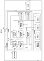
- FIG. 1 is a block diagram illustrating an example of a main configuration of a television 10 on which the noise reduction device 1 (display control device) according to the present embodiment is mounted.
- FIG. 2 is a diagram illustrating the television 10 (display device, television receiver). It is an external view which shows an example of the external appearance of a machine.
- the noise reduction device 1 controls the display of an image on the television 10. Specifically, the noise reduction device 1 reduces color noise of an image displayed on the television 10. More specifically, the noise reduction device 1 determines pixels for reducing noise in a still image (hereinafter referred to as a frame) that constitutes video content (for example, a received broadcast program) to be displayed on the television 10. The threshold value corresponding to the luminance of the frame is determined. Then, the color noise is reduced by reducing the saturation of the pixel having the luminance smaller than the determined threshold while maintaining the luminance.
- a frame that constitutes video content (for example, a received broadcast program)
- the noise reduction device 1 is described as being mounted on the television 10 shown in FIG.
- the device on which the noise reduction device 1 is mounted is not limited to a television receiver.
- the noise reduction device 1 is mounted on, for example, a playback device (player) that plays back recorded video, a display device (monitor) that does not have a tuner, a set-top box, a tuner for receiving cable TV broadcasting, satellite broadcasting, or the like. May be.
- the playback device may be integrated with a recording device that records a broadcast program.
- FIG. 1 is a figure which shows only the member with high relevance to this invention among the members with which the television 10 is provided. Further, illustration and detailed description of members having low relevance to the present invention are omitted.
- the television 10 includes a broadcast receiving unit 11 that receives a broadcast stream, a control unit 12 that controls and controls each unit of the television 10, a storage unit 13 that stores various data used in the television 10, and A display unit 14 for displaying the video of the broadcast program is provided.
- the broadcast receiving unit 11 receives a broadcast stream including a broadcast program broadcast by, for example, terrestrial digital broadcasting or satellite broadcasting.
- the broadcast receiving unit 11 is configured by an antenna and a tuner, for example.
- the control unit 12 includes a broadcast signal control unit 121, a luminance distribution generation unit 122 (maximum value specifying unit), a luminance coefficient determination unit 123, a saturation coefficient determination unit 124, a hue coefficient determination unit 125, and a calculation coefficient calculation unit 126. , A saturation correction unit 127 (saturation changing unit), and a video processing unit 128 are included. Further, the storage unit 13 stores luminance coefficient determination information 131, a luminance lookup table 132, a saturation lookup table 133, and a hue lookup table 134. In FIG. 1, the lookup table is denoted as LUT, and in the following description, the lookup table is denoted as LUT.
- the broadcast signal control unit 121 outputs information of each frame of the broadcast program included in the received broadcast stream to each unit of the control unit 12. Specifically, the broadcast signal control unit 121 outputs luminance information d1 indicating the luminance of each pixel of the frame and color difference information d2 indicating the saturation and hue of each pixel of the frame to the saturation correction unit 127. Also, the broadcast signal control unit 121 outputs the luminance information d1 to the luminance distribution generation unit 122. The broadcast signal control unit 121 also outputs the color difference information d2 to the saturation coefficient determination unit 124 and the hue coefficient determination unit 125.
- the broadcast signal control unit 121 acquires color component information (specifically, the values of the red component, green component, and blue component of each pixel of the frame), the broadcast component control unit 121 converts the color component information into luminance information d1 and color difference information. It converts into d2, and outputs it to each part of the control part 12 mentioned above.
- a known technique can be used as a method of converting the color component information into the luminance information d1 and the color difference information d2.
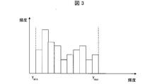
- the luminance distribution generation unit 122 generates a luminance distribution (luminance histogram) of the frame based on the acquired luminance information d1. For example, the luminance distribution generation unit 122 generates the luminance distribution shown in FIG. FIG. 3 is a diagram illustrating an example of the luminance distribution generated by the luminance distribution generation unit 122. Note that the luminance distribution generated by the luminance distribution generation unit 122 is not limited to the example of FIG. In addition, the luminance distribution generation unit 122 refers to the generated luminance distribution, and specifies a frame luminance maximum value Y max that is the maximum luminance value in the received frame and a frame luminance minimum value Y min that is the minimum value. And output to the luminance coefficient determination unit 123.
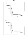
- the luminance coefficient determination unit 123 determines a luminance coefficient A Y (first coefficient) that is a coefficient corresponding to the luminance of the frame received by the television 10. Specifically, the luminance coefficient determination unit 123 first reads the luminance LUT 132 from the storage unit 13. The luminance LUT 132 stores information indicating the function of the luminance coefficient AY with respect to the luminance, for example, the function illustrated in FIG. FIG. 4 is a diagram illustrating an example of a function stored in the luminance LUT 132.
- the luminance factor A Y is maximum 1 in the range of brightness from 0 cd / m 2 to Y 1 cd / m 2. It takes 0 and decreases linearly in the range from Y 1 cd / m 2 to Y 2 cd / m 2, and becomes 0 in the range from Y 2 cd / m 2 .
- the numerical range considered low luminance in reducing target frame noise i.e., Y 2 cd / m 2 from 0 cd / m 2, hereinafter, a range of low brightness This is because the purpose is to reduce the color noise of the pixels included. More specifically, noise reduction device 1 according to this embodiment considers the range of 0 cd / m 2 to Y 1 cd / m 2 and noise reduction range, the saturation of the pixel to zero.
- the luminance coefficient A Y is a coefficient that decreases as the luminance increases in a range from Y 1 cd / m 2 to Y 2 cd / m 2 (a predetermined luminance range).
- the noise reduction device 1 regards the range from Y 1 cd / m 2 to Y 2 cd / m 2 as the adjustment range, and decreases the luminance coefficient A Y in a linear function as the luminance value increases. By providing this adjustment range, it is possible to suppress an abrupt change in saturation between a pixel whose saturation is 0 and a pixel whose saturation is not reduced.
- the luminance coefficient determination unit 123 determines the value Y 1 and the value Y 2 in the luminance LUT 132, and determines the luminance coefficient A Y for each luminance of the frame. Specifically, the luminance coefficient determination unit 123 reads the luminance coefficient determination information 131 from the storage unit 13, and defines a range of low luminance in the frame from the frame luminance maximum value Y max and the read luminance coefficient determination information 131. To do.
- the luminance coefficient determination information 131 includes a low luminance range determination coefficient B, noise reduction range determination information, and adjustment range determination information.
- the low luminance range determination coefficient B is a coefficient for determining the noise reduction range and the adjustment range.
- the low luminance range determination coefficient B is a coefficient for defining a low luminance range in the frame.
- the low luminance range determination coefficient B 0.005 will be described, but the present invention is not limited to this example.
- Noise reduction range determination information is information for determining the value Y 1.
- the noise reduction range determination information may be information that can determine the value Y 1 , It is not limited to this example.
- Adjustment range determination information is information for determining the value Y 2.
- the adjustment range determination information may be information that can determine the value Y 2 , and this example It is not limited to.
- the luminance coefficient determination unit 123 determines the value Y 1 as 0.5 cd / m 2 and sets the value Y 2 as 1 cd / m 2 . decide. Then, the luminance coefficient determination unit 123 determines the luminance coefficient A Y for the luminance of each pixel of the received frame by substituting the value Y 1 , the value Y 2 , and the frame luminance maximum value Y max into the luminance LUT 132. As shown in FIG. 4 (a), the brightness coefficient A Y according to the present embodiment, it becomes 0 for the pixel value Y 2 or more brightness.
- the value Y 2 of the present embodiment is a value indicating the 1% intensity with respect to the frame luminance maximum value Y max. That is, the luminance coefficient determination unit 123 according to the present embodiment sets the luminance coefficient AY of pixels having a luminance equal to or higher than a predetermined ratio to the frame luminance maximum value Ymax to zero. Although details will be described later, the noise reduction apparatus 1 does not reduce the saturation of pixels with the luminance coefficient AY being zero. In other words, the noise reduction device 1 includes a pixel having a value Y 2 is smaller than the luminance reducing saturation. That is, the luminance coefficient determination unit 123 can also be expressed as determining a first threshold value (value Y 2 , first value) according to the luminance of the image for determining a pixel for reducing noise.
- the luminance coefficient determination unit 123 further determines a second threshold value (value Y 1 , second value) in the luminance of the image, and the noise reduction device 1 is included in the range of the luminance from 0 to the value Y 1. saturation and 0 for pixels, a pixel whose luminance is within the range from the value Y 1 of the value Y 2 is to reduce the degree of decrease of the saturation as the brightness is increased, and can be expressed.
- the luminance coefficient determination unit 123 outputs the determined luminance coefficient AY to the calculation coefficient calculation unit 126.
- the function stored in the luminance LUT 132 is not limited to the example of FIG.
- a period from a value Y 1 to the value Y 2 may be a function which decreases quadratically. That is, in the function stored in the luminance LUT 132, the range from the value Y 1 to the value Y 2 may be any attenuation function.
- the attenuation function is a function other than a linear function, it is desirable to configure the noise reduction device 1 so that an arithmetic processor for preparing the attenuation function can be used.
- the function stored in the luminance LUT 132 may be a function in which the luminance coefficient decreases stepwise as the luminance increases (for example, the luminance coefficient decreases as the luminance increases by 2).
- the luminance coefficient determination unit 123 may set the luminance coefficient AY to 0 regardless of the luminance of the pixel of the frame when the frame luminance minimum value Ymin exceeds a predetermined value (for example, 5 cd / m 2 ). As a result, when the frame is generally bright, noise reduction processing based on luminance is not performed, so that a situation where saturation is excessively reduced can be prevented.
- the Saturation factor determination unit 124 determines the saturation factor A S is a coefficient corresponding to the saturation of the frame in which the television 10 has received. Specifically, when the saturation coefficient determination unit 124 acquires the color difference information d2 from the broadcast signal control unit 121, first, it calculates the saturation S of each pixel. Specifically, the color difference information d2 acquired by the saturation coefficient determination unit 124 includes a blue system color difference C b indicating the saturation and hue of the blue system, and a red system color difference C r indicating the saturation and hue of the red system. And are included.
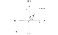
- the relationship between the saturation S and the hue H, and the blue system color difference Cb and the red system color difference Cr will be described with reference to FIG. FIG.
- FIG. 5 is a plane coordinate showing a relationship between the saturation S and the hue H, and the blue system color difference Cb and the red system color difference Cr .
- the saturation S of a certain color P (C b , C r ) is expressed by the origin O and the point P (in other words, the line segment length of the OP) the distance between the angle formed between a straight line passing through
- This arithmetic expression is an example, and the method of calculating the saturation S is not limited to this example.
- are absolute values of the blue system color difference C b and the red system color difference C r , respectively.
- the saturation S is for, the higher the absolute value of the bluish color difference C b and reddish color difference C r is large, the method of calculating the saturation S is as long as it performs operations such as can show this relationship Good.
- the saturation coefficient determination unit 124 reads the saturation LUT 133 from the storage unit 13.
- the saturation LUT133 is stored information indicating a function of the saturation factor A S for saturation S, for example, a function shown in FIG. 6 is stored.
- FIG. 6 is a diagram illustrating an example of functions stored in the saturation LUT 133.
- Saturation factor determination unit 124 the calculated saturation S substituted into the function number, to determine the saturation factor A S for saturation of each pixel of the received frame.
- the saturation coefficient determination unit 124 outputs the determined saturation coefficient AS to the calculation coefficient calculation unit 126.
- the function stored in the chroma LUT133 may be any function, such as the value of the saturation factor A S the greater the saturation S of the pixel is large, not limited to the example of FIG. 6.
- the hue coefficient determination unit 125 reads the hue LUT 134 from the storage unit 13.
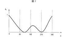
- Hue LUT134 is stored information indicating a function of the hue coefficients A H is for hue H, for example, a function shown in FIG. 7 is stored.
- FIG. 7 is a diagram illustrating an example of functions stored in the hue LUT 134.
- the hue coefficient determination unit 125 substitutes the calculated hue H into the function, and determines the hue coefficient A H for the hue of each pixel of the received frame. In other words, the hue coefficients A H is according to the hue of each pixel of the frame, it can be expressed as a coefficient for each pixel. Then, the hue coefficient determination unit 125 outputs the determined hue coefficient AH to the calculation coefficient calculation unit 126.
- the arithmetic expression for calculating the arithmetic coefficient AT is an example, and the present invention is not limited to this example.
- the calculation coefficient calculation unit 126 outputs the calculated calculation coefficient AT to the saturation correction unit 127.
- the calculation coefficient AT according to the present embodiment is a coefficient proportional to the luminance coefficient AY . That is, the calculation coefficient AT according to the present embodiment increases as the brightness coefficient AY increases.
- the calculation coefficient AT according to the present embodiment includes the saturation coefficient A S determined based on the function (see FIG. 6) stored in the saturation LUT 133 and the function stored in the hue LUT 134 (FIG. 7). it is a coefficient proportional to the hue coefficients a H which is determined based on the reference). That is, the arithmetic coefficient AT according to the present embodiment has a larger value as the saturation is larger, and a larger value as the hue is closer to blue and yellow.
- the saturation correction unit 127 reduces the saturation of the pixels included in the low luminance range among the pixels of the frame.
- the video processing unit 128 includes the blue system color difference C b and the red system color difference C r included in the color difference information d2 acquired from the broadcast signal control unit 121, and the calculation coefficient A T acquired from the calculation coefficient calculation unit 126. from, the corrected (in other words, decreased saturation) calculates bluish color difference C b and reddish color difference C r a is bluish color difference C b 'and reddish color difference C r', respectively.
- the blue system color difference C b ′ and the red system color difference C r ′ are calculated.
- the saturation correction unit 127 outputs the calculated blue system color difference C b ′ and red system color difference C r ′ to the video processing unit 128.
- the saturation correction by the saturation correction unit 127 will be described in detail. Although details will be described later, the video processing unit 128 causes the display unit 14 to display a frame based on the luminance information d1, the blue system color difference C b ′, and the red system color difference C r ′ acquired from the saturation correction unit 127. As described above, the blue system color difference C b ′ and the red system color difference C r ′ are obtained by multiplying the obtained blue system color difference C b and red system color difference C r by a value obtained by subtracting the operation coefficient AT from 1, respectively. Is required.
- the saturation correction unit 127 changes the values of the blue system color difference C b and the red system color difference C r to the blue system color difference C b ′ and the red system color difference C r ′, respectively, and is displayed on the display unit 14. The saturation of each pixel of the frame is changed from the saturation of each pixel of the received frame.
- the calculation coefficient A T is calculated by multiplying the luminance coefficient A Y , the saturation coefficient A S , and the hue coefficient A H. That is, the calculation coefficient A T becomes larger as the values of the luminance coefficient A Y , the saturation coefficient A S , and the hue coefficient A H are larger.
- the calculation coefficient AT is also a value of 0 or more and 1 or less, and similarly (1 -A T ) is also a value between 0 and 1.
- the saturation S (the saturation S of each pixel in the frame displayed on the display unit 14) based on the blue system color difference C b ′ and the red system color difference C r ′ is smaller as the arithmetic coefficient AT is larger.
- the difference from the saturation S of each pixel in the received frame increases (in other words, the greater the luminance coefficient AY , the greater the degree of decrease in saturation S).
- brightness coefficient A Y when the luminance of each pixel is not included in the scope of the low-intensity (range 0 cd / m 2 of Y 2 cd / m 2), the value Becomes 0. That is, for the pixels whose luminance is not included in the low luminance range, the calculation coefficient AT is 0, so that the noise reduction device 1 does not correct the saturation of the pixel (the saturation does not decrease). That is, the noise reduction device 1 according to the present embodiment reduces only the saturation of the pixels included in the low luminance range.
- the luminance information d1 of the received frame is output to the video processing unit 128 as it is. Therefore, the frame displayed on the display unit 14 maintains the luminance of each pixel of the received frame.
- the broadcast signal control unit 121 may output the luminance information d1 to the video processing unit 128 instead of the saturation correction unit 127.
- the hue of each pixel of the frame displayed on the display unit 14 is the one in which the hue H of each pixel of the received frame is maintained.
- the video processing unit 128 causes the display unit 14 to display a frame based on the acquired luminance information d1, the blue system color difference C b ′, and the red system color difference C r ′. As a result, the display unit 14 displays a frame in which the saturation is corrected (the saturation is reduced) in the pixels included in the low luminance range.
- the noise reduction device 1 since the noise reduction device 1 according to the present embodiment reduces the saturation at the low-luminance pixel, it is possible to suppress the occurrence of color noise at the pixel. Also, noise reduction processing can be performed only on pixels that need noise reduction. Further, since the luminance of each pixel is maintained, it is possible to suppress the occurrence of a blurred region or a blackened region due to the luminance reduction.
- FIG. 8 is a flowchart illustrating an example of the flow of noise reduction processing executed by the noise reduction apparatus 1.
- the broadcast signal control unit 121 waits for reception of a broadcast program frame (step S1, hereinafter, “step” is omitted).
- step S1 the broadcast signal control unit 121 outputs the luminance information d1 and the color difference information d2 to the saturation correction unit 127.
- the broadcast signal control unit 121 outputs the luminance information d1 to the luminance distribution generation unit 122.
- the broadcast signal control unit 121 also outputs the color difference information d2 to the saturation coefficient determination unit 124 and the hue coefficient determination unit 125.
- the luminance distribution generation unit 122 generates a luminance distribution using the acquired luminance information d1 (S2). Then, referring to the generated luminance distribution, the frame luminance maximum value Y max and the frame luminance minimum value Y min are specified and output to the luminance coefficient determination unit 123.
- the luminance coefficient determination unit 123 defines a low luminance range in the received frame (S3). Specifically, the luminance coefficient determination unit 123 sets the value Y 1 and the value Y 2 in the function stored in the luminance LUT 132 read from the storage unit 13, the acquired frame luminance maximum value Y max, and the storage unit 13. calculated from the low-luminance range determining coefficients B read, defining the low luminance range (in other words, specific numerical values Y 2). Subsequently, the luminance coefficient determination unit 123 determines the luminance coefficient AY (S4).
- the luminance coefficient A Y with respect to the luminance of each pixel of the received frame.
- the luminance coefficient AY for luminance not included in the low luminance range is zero.
- the luminance coefficient determination unit 123 outputs the determined luminance coefficient AY to the calculation coefficient calculation unit 126.
- the chroma coefficient determining unit 124 determines the saturation factor A S (S5). More specifically, to calculate the saturation S and a bluish color difference C b and reddish color difference C r contained in the color difference information d2 obtained, is stored in the chroma LUT133 read from the storage unit 13 functions, by substituting the calculated saturation S, to determine the saturation factor a S for saturation of each pixel of the received frame.
- the saturation coefficient determination unit 124 outputs the determined saturation coefficient AS to the calculation coefficient calculation unit 126.
- the hue coefficient determining unit 125 determines the hue coefficients A H (S6). Specifically, calculates the hue H and a bluish color difference C b and reddish color difference C r contained in the color difference information d2 obtained, the function stored in the hue LUT134 read from the storage unit 13, and calculates By assigning the hue H, the hue coefficient A H for the hue of each pixel of the received frame is determined.
- the hue coefficient determination unit 125 outputs the determined hue coefficient AH to the calculation coefficient calculation unit 126.
- process of S4, S5, and S6 should just be performed before the process of S7 after the process of S3, The order is not specifically limited. Further, the processes of S4, S5, and S6 may be performed simultaneously.
- the calculation coefficient calculation unit 126 calculates a calculation coefficient AT from the acquired luminance coefficient A Y , saturation coefficient A S , and hue coefficient A H (S7). Then, the calculation coefficient calculation unit 126 outputs the calculated calculation coefficient AT to the saturation correction unit 127.
- the video processing unit 128 displays the corrected frame on the display unit 14 (S9). Specifically, the video processing unit 128 causes the display unit 14 to display a frame based on the acquired luminance information d1, the blue system color difference C b ′, and the red system color difference C r ′. As a result, the display unit 14 displays a frame in which the saturation is corrected (the saturation is reduced) in the pixels included in the low luminance range.
- the low luminance range determination coefficient B included in the luminance coefficient determination information 131 described above is a constant value regardless of the frame luminance maximum value Y max , but the low luminance range determination coefficient B is the frame luminance maximum value Y max. It may be a value according to. Details of this modification will be described with reference to FIG. FIG. 9 is a graph for explaining the low luminance range determination coefficient B that changes in accordance with the frame luminance maximum value Ymax .
- the storage unit 13 of the noise reduction apparatus 1 according to the present modification stores an LUT that stores the function shown in FIG.
- the luminance coefficient determination unit 123 reads the LUT, and specifies a low luminance range determination coefficient B corresponding to the acquired frame luminance maximum value Y max from the illustrated function.
- the function for specifying the low luminance range determination coefficient B is not limited to the illustrated example. However, even when the frame luminance maximum value Y max is large, it is possible to perform the noise reduction process only on pixels that are likely to cause color noise (in other words, pixels having low luminance values). Therefore, as shown in the figure, when the frame luminance maximum value Y max is equal to or greater than a predetermined value, the function is such that the low luminance range determination coefficient B gradually decreases as the frame luminance maximum value Y max increases. desirable.
- FIG. 10 is a block diagram illustrating an example of a main configuration of the television 10a according to the present embodiment.
- the television 10a in other words, the noise reduction device 1a mounted on the television 10a
- the maximum luminance information Maximum Content Light Level
- an appropriate low luminance range is defined for each frame of the content. The details will be described below.
- the television 10 a includes a control unit 12 a instead of the control unit 12.
- the control unit 12a includes a broadcast signal control unit 121a and a luminance coefficient determination unit 123a instead of the broadcast signal control unit 121 and the luminance coefficient determination unit 123, respectively.
- the broadcast signal control unit 121a outputs the maximum luminance information d3 included in the broadcast stream to the luminance coefficient determination unit 123a in addition to the function of the broadcast signal control unit 121 described above.
- the maximum luminance information d3 is information indicating the highest luminance in the content. That is, in the present embodiment, the maximum luminance information d3 is one value for one content.
- the maximum luminance information d3 is information included in the first frame in the content. Therefore, when the broadcast signal control unit 121a acquires the first frame in the content, the broadcast signal control unit 121a outputs the maximum luminance information d3 included in the frame to the luminance coefficient determination unit 123a.
- the maximum luminance information d3 may not be one value for one content.
- the maximum luminance information d3 may be information indicating the highest luminance in each segment when the content is divided into several segments. In this case, the maximum luminance information d3 exists as many as the number of segments for one content. In this case, the maximum luminance information d3 is included in the first frame in each segment.
- the maximum luminance information d3 may be information indicating the highest luminance in each frame.
- the maximum luminance information d3 exists as many as the number of frames for one content.
- the maximum luminance information d3 is included in each frame.
- the maximum luminance information d3 is information indicating the highest luminance in each frame
- the maximum luminance information d3 and the frame luminance maximum value Y max are likely to be the same value.
- the maximum luminance information d3 is a value set on the content transmission side
- the frame luminance maximum value Y max is the highest luminance in the luminance distribution generated in the noise reduction device 1a (that is, reception of content).
- the value may be a different value.
- the maximum luminance information d3 may be expressed as a maximum luminance value MaxCLL.
- the value Y 1 and the value Y 2 are calculated using the calculated low luminance range determination coefficient B ′. Note that a specific calculation method of the value Y 1 and the value Y 2 has been described in the first embodiment, and thus description thereof is omitted here.
- FIG. 11 is a diagram illustrating a difference in a low luminance range according to a difference in a ratio (that is, Y max / Max CLL) between the maximum luminance information d3 (that is, the maximum luminance value MaxCLL) and the frame luminance maximum value Y max . is there.
- the low-luminance range determining factor B 0.005
- the low-luminance range determining coefficients B ' also 0.005
- the arithmetic expression value Y 2 is the same as Embodiment 1
- low The luminance range is a luminance range of 0 to 1% with respect to the frame luminance maximum value Y max .
- the noise reduction device 1a when the frame luminance maximum value Y max is smaller than the maximum luminance in the content, if the low luminance range is a luminance range of 0 to 1% with respect to the frame luminance maximum value Y max , noise reduction is necessary. There is a risk that noise reduction may be performed on pixels that do not have any. Accordingly, the noise reduction device 1a according to the present embodiment further narrows the low luminance range when the frame luminance maximum value Y max is smaller than the maximum luminance in the content. Thereby, noise reduction can be performed only for pixels that need noise reduction. A specific example is shown in FIG. FIG.
- the low luminance range is a luminance of 0 to 0.5% with respect to the frame luminance maximum value Y max . It becomes the range.
- the low luminance range determination coefficient B ′ predetermined ratio
- the low luminance range determination coefficient B ′ is expressed as being small when the difference between the frame luminance maximum value Y max and the maximum luminance value MaxCLL is large, and large when the difference is small. You can also.
- the noise reduction device 1a corrects the low luminance range determination coefficient B according to the ratio (Y max / Max CLL) between the maximum luminance value MaxCLL and the frame luminance maximum value Y max .
- the ratio (Y max / Max CLL) between the maximum luminance value MaxCLL and the frame luminance maximum value Y max .
- the luminance coefficient determination unit 123a described above uses the maximum luminance value MaxCLL to correct the low luminance range determination coefficient B, but the method of using the maximum luminance value MaxCLL is not limited to this example.
- the brightness coefficient determining section 123a has a maximum luminance value MaxCLL, be used in place of the frame luminance maximum value Y max, may calculate the value Y 1 and the value Y 2.
- the noise reduction device 1a replaces the maximum luminance information d3 with the average luminance information (Maximum Frame Average Light Level, hereinafter referred to as the average luminance) indicating the average luminance (average luminance of the content) included in the broadcast stream.
- the information may be referred to as an average luminance value MaxFALL), and an appropriate low luminance range may be defined for each frame of content.
- the specific processing executed by the luminance coefficient determination unit 123a in this case is the same as the processing described above except that the maximum luminance value MaxCLL is replaced with the average luminance value MaxFALL in the processing described above. Description is omitted.
- the noise reduction apparatus 1a replaces the maximum brightness information d3 with the content creation maximum brightness information indicating the maximum brightness on the monitor (display device) used when the content creator creates the content, which is included in the broadcast stream.
- Luminance) may be used and the suitable low-intensity range may be defined for every frame of a content. Note that the specific processing executed by the luminance coefficient determination unit 123a in this case is the same as the processing described above, except that the maximum luminance value MaxCLL is replaced with the value in the maximum luminance information at the time of content creation in the processing described above. Therefore, explanation here is omitted.
- FIG. 12 is a block diagram illustrating an example of a main configuration of the television 10b according to the present embodiment.
- the television 10b (in other words, the noise reduction device 1b mounted on the television 10b) is in response to an input signal input by the user using the remote controller (hereinafter referred to as the remote controller 20) of the television 10b (in other words, in other words).
- the remote controller 20 the remote controller of the television 10b (in other words, in other words).
- the remote controller 20 the remote controller of the television 10b (in other words, in other words).
- the remote controller 20 the remote controller of the television 10b (in other words, in other words).
- the television 10 b includes a control unit 12 b instead of the control unit 12.
- the television 10b further includes a remote control receiver 15 that receives a signal transmitted from the remote controller 20 (hereinafter referred to as a remote control signal).
- the control unit 12b includes a broadcast signal control unit 121b, a luminance coefficient determination unit 123b, and a calculation coefficient calculation instead of the broadcast signal control unit 121, the luminance coefficient determination unit 123, the calculation coefficient calculation unit 126, and the video processing unit 128. A part 126b and a video processing part 128b are included. Further, the control unit 12b newly includes a remote control signal control unit 129.
- the broadcast signal control unit 121b has the same configuration as the broadcast signal control unit 121a described in the second embodiment, and a description thereof is omitted here.
- the remote control signal control unit 129 acquires the remote control signal from the remote control reception unit 15, the remote control signal control unit 129 identifies an operation instruction included in the remote control signal and outputs it to the luminance coefficient determination unit 123b or the calculation coefficient calculation unit 126b. Specifically, when the specified operation instruction is a low-luminance range determination coefficient B correction instruction d4, remote control signal control section 129 outputs correction instruction d4 to luminance coefficient determination section 123b. Further, when the specified operation instruction is the correction instruction d5 for the calculation coefficient AT , the remote control signal control unit 129 outputs the correction instruction d5 to the calculation coefficient calculation unit 126b.
- the remote control signal control unit 129 displays a UI for causing the identified operation instruction to display a user interface (hereinafter referred to as UI) for correcting the low-luminance range determination coefficient B and the calculation coefficient AT on the display unit 14. If the instruction is d6, the UI display instruction d6 is output to the video processing unit 128b.
- UI user interface
- the luminance coefficient determination unit 123b differs from the luminance coefficient determination unit 123 in the following points. That is, the luminance coefficient determination unit 123b corrects the read low luminance range determination coefficient B according to the acquired correction instruction d4. For example, when the correction instruction d4 is an instruction for doubling the low luminance range determination coefficient, the luminance coefficient determination unit 123b reduces the low luminance range determination coefficient B "by doubling the low luminance range determination coefficient B according to the instruction. And the luminance coefficient AY is determined based on the low luminance range determination coefficient B ′′.
- the luminance coefficient determination unit 123b uses the acquired maximum luminance value MaxCLL and the maximum frame luminance value Y max as in the luminance coefficient determination unit 123a described in the second embodiment, and calculates the low luminance range determination coefficient B ′. It may be configured to correct. In the case of this example, the luminance coefficient determination unit 123b further corrects according to the correction instruction d4 that acquired the low luminance range determination coefficient B ′.
- the correction instruction d4 may be an instruction for changing (correcting) the low luminance range, and the value corrected by the instruction is not limited to the low luminance range determination coefficient B.
- the luminance coefficient determination unit 123b may correct the maximum luminance value MaxCLL according to the correction instruction d4.
- the calculation coefficient calculation unit 126b is different from the calculation coefficient calculation unit 126 in the following points. That is, the calculation coefficient calculation unit 126b corrects the calculated calculation coefficient AT according to the acquired correction instruction d5. For example, if the correction instruction d5 was 0.5 multiply instruction calculation coefficients A T, the calculation coefficient calculation unit 126b, the arithmetic coefficient calculation coefficient was 0.5 times the operational coefficient A T in response to the instruction A T 'Is calculated, and this calculation coefficient calculation coefficient A T ' is output to the saturation correction unit 127.
- the video processing unit 128b differs from the video processing unit 128 in the following points. That is, when acquiring the UI display instruction d6 from the remote control signal control unit 129, the video processing unit 128b causes the display unit 14 to display a UI for correcting the low-luminance range determination coefficient B and the calculation coefficient AT .
- the UI is not particularly limited as long as it can accept correction of the low luminance range determination coefficient B and the calculation coefficient AT .
- the UI may be as shown in FIG.
- FIG. 13 is a diagram illustrating an example of a UI displayed on the display unit 14.
- the video processing unit 128 b may cause the display unit 14 to display a UI 141 that receives an input for correcting the low luminance range determination coefficient B (or the maximum luminance value MaxCLL).
- the UI 141 is a slider in which the handle portion 411 (circular portion of the UI 141) moves on the slider portion 412 (rectangular portion of the UI 141) in response to the user operating the remote controller 20.
- the UI 141 indicates that the handle portion 411 corresponds to the lower limit display 413 (text “0”) of the slider portion 412 (ie, (a) in FIG. 13) in response to the user operating the remote controller 20.
- the lower limit display 413 is a display indicating the lower limit position of the slider portion 412
- the upper limit display 414 is a display indicating the upper limit position of the slider portion 412.
- the display unit 14 displays a text “Dark part noise reduction” indicating a process executed when the user operates the remote controller 20 when the screen shown in FIG. 13A is displayed. Yes.
- the remote control signal control unit 129 corresponds to the lower limit display 413 (text “0”) on the slider unit 412, in which the handle unit 411 of the UI 141 is from the left end to the right end in FIG. 13A of the slider unit 412.
- the low luminance range determination coefficient B is corrected according to the position.
- An instruction to that effect is output to the luminance coefficient determination unit 123b as a correction instruction d4.
- the remote control signal control unit 129 changes the amount of change in the low luminance range determination coefficient B with respect to the value indicating the position of the handle unit 411 in the slider unit 412 stored in the storage unit 13 (in other words, low luminance A LUT (not shown) storing a function of a value indicating how many times the range determination coefficient B is multiplied is read out. Then, a value indicating the position of the handle portion 411 in the slider portion 412 is substituted into the function to specify the amount of change in the low luminance range determination coefficient B.
- the function is, for example, a value indicating that the position of the handle portion 411 in the slider portion 412 is a position corresponding to the lower limit display 413 (text “0”) in the slider portion 412, and the low luminance range determination coefficient B
- the change amount of the low luminance range determination coefficient B is 0 when the change amount of the handle portion 411 is a value indicating that the position of the handle portion 411 corresponds to the upper limit display 414 (text “+10”) in the slider portion 412.
- a linear function that doubles the amount may be used.
- the function described here is an example, and the function is not limited to this example.
- the video processing unit 128b corrects the UI 142 that receives an input for correcting the low luminance range determination coefficient B (or the maximum luminance value MaxCLL), and the arithmetic coefficient AT .
- a UI 143 that accepts an input for performing the input may be displayed on the display unit 14.
- the UI 142 and the UI 143 are described as being sliders in which the handle portion 411 moves to any one of 11 positions in the slider portion 412 in response to the user operating the remote controller 20 in the same manner as the UI 141 described above. It is not limited to this example.
- the UI 142 includes the text “narrow” as the lower limit display 413 and the text “wide” as the upper limit display 414.
- the UI 142 further includes an intermediate display 415 (text “middle”) indicating a position corresponding to the center of the slider portion 412.
- the UI 143 includes the text “small” as the lower limit display 413, and includes the text “large” as the upper limit display 414.
- the UI 143 includes the text “medium” as the intermediate display 415.
- the display unit 14 includes texts “reduction area” and “reduction amount” that indicate processing executed when the user operates the remote controller 20 when the screen shown in FIG. 13B is displayed. Are displayed adjacent to UI 142 and UI 143, respectively.
- the remote control signal control unit 129 corresponds to the lower limit display 413 (the text “narrow”) on the slider unit 412 where the handle unit 411 of the UI 142 is from the left end to the right end in FIG. 13B of the slider unit 412.
- the low luminance range determination coefficient B is corrected according to the position. Is output to the luminance coefficient determination unit 123b as a correction instruction d4. This process is the same as the process performed when the handle portion 411 of the UI 141 described above is acquired as a remote control signal that the handle portion 411 of the UI 141 has moved on the slider portion 412, and thus the description thereof is omitted here.
- the remote control signal control unit 129 changes the handle portion 411 of the UI 143 from the left end to the right end in FIG. 13B of the slider portion 412, in other words, the lower limit display 413 (text “small”) on the slider portion 412.
- the arithmetic coefficient AT is corrected according to the position. Is output to the calculation coefficient calculation unit 126 as a correction instruction d5.
- the remote control signal control unit 129 changes the amount of change in the operation coefficient AT with respect to the value stored in the storage unit 13 and indicating the position of the handle unit 411 in the slider unit 412 (in other words, the operation coefficient A T LUT (not shown) storing a function of a value indicating how many times is multiplied) is read. Then, a value indicating the position of the handle portion 411 in the slider portion 412 is substituted into the function, and the change amount of the calculation coefficient AT is specified. For example, when the function is a value indicating that the position of the handle unit 411 in the slider unit 412 corresponds to the lower limit display 413 (text “small”) in the slider unit 412, the change in the calculation coefficient AT is performed.
- the amount of change in the calculation coefficient AT is 0. It may be a linear function that becomes 1 time.
- the function described here is an example, and the function is not limited to this example.
- the remote control signal control unit 129 may be configured to output the remote control signal acquired from the remote control reception unit 15 to the luminance coefficient determination unit 123b, the calculation coefficient calculation unit 126b, or the video processing unit 128b as it is.
- the remote control signal control unit 129 determines the output destination of the acquired remote control signal and outputs the remote control signal to the determined output destination.
- the luminance coefficient determination unit 123b and the calculation coefficient calculation unit 126b correct the low luminance range determination coefficient B or the calculation coefficient AT according to the remote control signal.
- the video processing unit 128b causes the display unit 14 to display a UI corresponding to the remote control signal.
- the remote controller 20 and the remote control receiver 15 are described as examples of members that receive user input operations.
- members that receive user input operations are not limited to this example.
- a physical button provided on the television 10b or a touch panel provided so as to be superimposed on the display unit 14 may be used.
- the remote controller 20 may have only a physical button as shown in FIG. 13, or may have a touch panel in addition to the physical button or instead of the physical button.
- the television 10b may allow the user to select a content display mode and correct the low luminance range determination coefficient B or the maximum luminance value MaxCLL in accordance with the display mode selected by the user.
- the video processing unit 128b may cause the display unit 14 to display a UI for allowing the user to select a content display mode.
- the UI is not particularly limited as long as the user can select a content display mode.
- the UI may be as shown in FIG.
- FIG. 14 is a diagram illustrating another example of a UI displayed on the display unit 14. In this modification, an example in which the maximum luminance value MaxCLL is corrected will be described.
- the UI 144a, UI 144b, and UI 144c shown in FIG. 14 are UIs for accepting a change in content display mode.
- UI 144 when it is not necessary to distinguish between the UI 144a, the UI 144b, and the UI 144c, they are referred to as UI 144.
- the display unit 14 displays a text “select display mode” indicating a process executed when the user operates the remote controller 20 when the screen shown in FIG. 14 is displayed.
- “Dynamic mode” is a mode in which video processing is performed so that content is displayed vividly (specifically, the saturation of each pixel is increased). This mode is suitable for video images.
- “Movie mode” is a mode in which video processing is performed so as to suppress the vividness of the content (specifically, the saturation of each pixel is lowered), and this mode is suitable when the content is a movie or the like. It is.
- the “standard mode” is a mode in which video processing corresponding to content is not performed on the television 10b.
- the content display mode described here is an example, and the content display mode is not limited to this example.
- the remote control signal control unit 129 When the remote control signal control unit 129 acquires the remote control signal indicating which display mode is selected, the amount of change in the maximum luminance value MaxCLL (in other words, how many times the maximum luminance value MaxCLL is increased) according to the acquired remote control signal. Change the value). Specifically, when a remote control signal indicating that the “standard mode” has been selected is acquired, the remote control signal control unit 129 sends a correction instruction d4 for making the change amount of the maximum luminance value MaxCLL to 1 to the luminance coefficient determination unit 123b. Output. Note that when “standard mode” is selected, the maximum luminance value MaxCLL does not change, so the remote control signal control unit 129 may be configured not to output the correction instruction d4.
- the remote control signal control unit 129 When the remote control signal indicating that the “dynamic mode” is selected is acquired, the remote control signal control unit 129 outputs a correction instruction d4 for increasing the change amount of the maximum luminance value MaxCLL by 1.5 times to the luminance coefficient determination unit 123b.
- the dynamic mode is a mode in which video processing is performed so as to increase the saturation of each pixel, so that there is a high possibility that color noise is enhanced. That is, as described above, the maximum luminance value MaxCLL is multiplied by 1.5 to expand the low luminance range (that is, the range in which the saturation is reduced), so that the color noise is caused by the “dynamic mode”. Color noise can be suppressed for pixels that are likely to occur (in other words, pixels that are newly included in the low luminance range by correcting the maximum luminance value MaxCLL).
- the remote control signal control unit 129 When a remote control signal indicating that “movie mode” has been selected is acquired, the remote control signal control unit 129 outputs a correction instruction d4 for increasing the change amount of the maximum brightness value MaxCLL to 0.5 times to the brightness coefficient determination unit 123b. To do. This is a mode in which the movie mode performs video processing so as to lower the saturation of each pixel. Therefore, if the low luminance range is not corrected, the saturation is reduced even for pixels that do not require noise reduction. This is because there is a risk of losing. In other words, as described above, the maximum luminance value MaxCLL is multiplied by 0.5 to reduce the low luminance range (that is, the range in which the saturation is reduced), so that overcorrection in the content can be prevented. Note that the amount of change in the maximum luminance value MaxCLL described here is an example, and is not limited to this example.
- the luminance coefficient determination unit 123, the luminance coefficient determination unit 123a, and the luminance coefficient determination unit 123b (hereinafter, referred to as the luminance coefficient determination unit 123 when there is no need to distinguish between them) according to each embodiment described above according to the content
- the low luminance range determination coefficient B or the maximum luminance value MaxCLL may be corrected.
- the luminance coefficient determination unit 123 acquires information (for example, a movie, a sports broadcast, a drama, etc.) indicating the type of content from the broadcast signal control unit 121, and the low luminance range determination coefficient B according to the information.
- the maximum luminance value MaxCLL is corrected.
- the maximum luminance value MaxCLL is multiplied by 0.5.
- the maximum luminance value MaxCLL is multiplied by 1.5.
- the luminance coefficient determination unit 123 may acquire information indicating the type of content from an EPG (Electronic Program Guide).
- the calculation coefficient calculation unit 126 and the calculation coefficient calculation unit 126b (hereinafter referred to as the calculation coefficient calculation unit 126 when there is no need to distinguish them) according to each of the embodiments described above are the luminance coefficient A Y , saturation
- the calculation coefficient AT is calculated using the coefficient A S and the hue coefficient A H
- the present invention is not limited to this example.
- the calculation coefficient calculation unit 126 may determine the calculation coefficient AT using at least the luminance coefficient AY . When only the luminance coefficient AY is used, the calculation coefficient calculation unit 126 outputs the acquired luminance coefficient AY to the saturation correction unit 127 as the calculation coefficient AT .
- control blocks of noise reduction apparatuses 1, 1a, and 1b may be realized by a logic circuit (hardware) formed in an integrated circuit (IC chip) or the like. However, it may be realized by software using a CPU (Central Processing Unit).
- a logic circuit hardware
- IC chip integrated circuit
- CPU Central Processing Unit
- the noise reduction devices 1, 1 a, and 1 b include a CPU that executes instructions of a program that is software that realizes each function, and a ROM (in which the program and various data are recorded so as to be readable by a computer (or CPU)) Read Only Memory) or a storage device (these are referred to as "recording media"), a RAM (Random Access Memory) for expanding the program, and the like.
- a computer or CPU
- a “non-temporary tangible medium” such as a tape, a disk, a card, a semiconductor memory, a programmable logic circuit, or the like can be used.
- the program may be supplied to the computer via an arbitrary transmission medium (such as a communication network or a broadcast wave) that can transmit the program.
- a transmission medium such as a communication network or a broadcast wave
- the present invention can also be realized in the form of a data signal embedded in a carrier wave in which the program is embodied by electronic transmission.
- the display control device (noise reduction device 1) according to aspect 1 of the present invention is a pixel having a first value corresponding to the luminance of an image to be displayed and smaller than the luminance corresponding to the first value. Is provided with a saturation changing unit (saturation correcting unit 127) that reduces the saturation while maintaining the luminance.
- the saturation is reduced for a pixel whose luminance is lower than the first value.
- the saturation is not reduced for pixels having a luminance equal to or higher than the first value. Therefore, it is possible to reduce the saturation only in the low luminance region of the image.
- the saturation of the pixels in the low luminance region decreases, the color difference from surrounding pixels becomes inconspicuous. Therefore, the color noise generated in the low luminance area of the image becomes inconspicuous. Therefore, the color noise generated in the low luminance area of the image can be made inconspicuous, and as a result, the color noise can be reduced.
- the luminance of the pixel whose saturation is reduced is maintained, so that the color noise can be reduced without reducing the information amount of the image.
- the display control apparatus further includes a maximum value specifying unit (brightness distribution generation unit 122) that specifies the maximum value of the luminance of the image in the above aspect 1, and the first value is The value may be a predetermined ratio with respect to the maximum value.
- a maximum value specifying unit (brightness distribution generation unit 122) that specifies the maximum value of the luminance of the image in the above aspect 1, and the first value is The value may be a predetermined ratio with respect to the maximum value.
- the first value is a value that is a predetermined ratio with respect to the maximum luminance value of the image.
- the display control apparatus is the display control apparatus according to aspect 2, wherein the predetermined ratio includes a maximum value of the luminance of the image and a maximum value of the luminance of the content set in advance for the content including the image.
- the difference may be small when the difference is large, and may be large when the difference is small.
- the predetermined ratio is small when the difference between the maximum value of the luminance of the image and the maximum value of the luminance of the content is large, and is large when the difference is small. Accordingly, depending on whether the noise reduction target image is a dark scene image or a bright scene image in the content, the noise reduction target pixel (in other words, the saturation reduction target pixel) is selected. Can be changed. Thereby, it is possible to perform optimum noise reduction in the image.
- the predetermined ratio may be changed according to a user operation.
- the predetermined ratio is changed according to the user operation, it is possible to change the pixel of the noise reduction target (in other words, the saturation reduction target) according to the user operation. As a result, it is possible to make the pixel targeted for noise reduction desirable for the user.
- the display control device may cause the display device to display a user interface for changing the predetermined ratio in aspect 4 above.
- the user interface for changing the predetermined ratio is displayed on the display device, the user can check the degree of change of the predetermined ratio. Therefore, it is possible to realize a display control device that is easy for the user to use.
- the display control device is the display control device according to any one of the aspects 1 to 5, wherein the saturation changing unit has a luminance value from 0 to a value corresponding to the luminance of the image.
- the saturation of the pixels included in the range of the second value having a smaller value is set to 0, and the luminance is decreased from the second value to the range of the pixels included in the range of the first value. You may make it small, so that it becomes large.
- the saturation is 0 for the pixels included in the range of the brightness from 0 to the second value
- the lower brightness area in other words, the color noise is present in the low brightness area.
- Color noise in a more conspicuous area can be appropriately reduced.
- the degree of decrease in saturation is reduced as the luminance increases, so that the luminance is particularly high among pixels having a small difference in luminance. It is possible to suppress a rapid change in saturation between pixels having values around the value of.
- the saturation changing unit may increase the degree of decrease in saturation for pixels whose hue is closer to blue.
- the color noise is more noticeable as the hue is closer to blue.
- the degree of decrease in saturation is increased as the pixel has a hue closer to blue. Therefore, the color noise that is more conspicuous can be made inconspicuous, so that more effective color noise reduction can be realized.
- the saturation changing unit may increase the degree of decrease in saturation as the pixel has higher saturation.
- the display device (television 10) according to aspect 9 of the present invention may include the display control device according to any one of aspects 1 to 8.
- the television receiver (television 10) according to aspect 10 of the present invention may include the display control device according to any one of aspects 1 to 8.
- the control method of the display control device is the first value corresponding to the luminance of the image to be displayed, and the luminance of the pixel having a luminance smaller than the luminance corresponding to the first value.
- the display control apparatus may be realized by a computer.
- the display control apparatus is operated on each computer by causing the computer to operate as each unit (software element) included in the display control apparatus.
- the display control device control program to be realized and a computer-readable recording medium on which the control program is recorded also fall within the scope of the present invention.
- Noise reduction device 10
- Television display device, television receiver
- luminance distribution generation unit maximum value specifying unit
- Saturation Correction Unit Saturation Change Unit
Abstract
Le procédé de l'invention permet de réduire le bruit de couleur dans une zone de faible luminosité d'une image, sans diminuer la valeur informative de l'image. Un dispositif de réduction de bruit (1) est équipé d'une unité de correction de saturation (127) qui diminue la saturation tout en maintenant la luminosité, au regard d'un pixel de luminosité inférieure à la luminosité représentée par une première valeur correspondant à la luminosité d'une image à afficher sur un téléviseur (10).
Priority Applications (2)
| Application Number | Priority Date | Filing Date | Title |
|---|---|---|---|
| US16/079,706 US20190052853A1 (en) | 2016-03-18 | 2017-02-15 | Display control device, display apparatus, television receiver, control method for display control device, and recording medium |
| CN201780013483.0A CN109076204A (zh) | 2016-03-18 | 2017-02-15 | 显示控制装置、显示装置、tv接收机、显示控制装置的控制方法、控制程序及记录介质 |
Applications Claiming Priority (2)
| Application Number | Priority Date | Filing Date | Title |
|---|---|---|---|
| JP2016056094A JP6190482B1 (ja) | 2016-03-18 | 2016-03-18 | 表示制御装置、表示装置、テレビジョン受像機、表示制御装置の制御方法、制御プログラム、及び記録媒体 |
| JP2016-056094 | 2016-03-18 |
Publications (1)
| Publication Number | Publication Date |
|---|---|
| WO2017159182A1 true WO2017159182A1 (fr) | 2017-09-21 |
Family
ID=59720365
Family Applications (1)
| Application Number | Title | Priority Date | Filing Date |
|---|---|---|---|
| PCT/JP2017/005422 WO2017159182A1 (fr) | 2016-03-18 | 2017-02-15 | Dispositif de commande d'affichage, appareil d'affichage, récepteur de télévision, procédé de commande de dispositif de commande d'affichage, programme de commande et support d'enregistrement |
Country Status (4)
| Country | Link |
|---|---|
| US (1) | US20190052853A1 (fr) |
| JP (1) | JP6190482B1 (fr) |
| CN (1) | CN109076204A (fr) |
| WO (1) | WO2017159182A1 (fr) |
Families Citing this family (4)
| Publication number | Priority date | Publication date | Assignee | Title |
|---|---|---|---|---|
| US11127370B2 (en) * | 2016-04-26 | 2021-09-21 | Sharp Kabushiki Kaisha | Field-sequential image display device and image display method |
| WO2018216498A1 (fr) * | 2017-05-25 | 2018-11-29 | ソニーセミコンダクタソリューションズ株式会社 | Dispositif de traitement d'image, procédé de traitement d'image et dispositif de projection |
| JP7341656B2 (ja) * | 2018-12-11 | 2023-09-11 | キヤノン株式会社 | 画像処理装置、制御方法、プログラム、及び、記憶媒体 |
| JP2021113847A (ja) * | 2020-01-16 | 2021-08-05 | キヤノン株式会社 | 表示装置および表示装置の制御方法 |
Citations (3)
| Publication number | Priority date | Publication date | Assignee | Title |
|---|---|---|---|---|
| JP2007336172A (ja) * | 2006-06-14 | 2007-12-27 | Fujifilm Corp | 画像信号処理装置及び画像信号処理方法 |
| JP2008099196A (ja) * | 2006-10-16 | 2008-04-24 | Sony Corp | 信号処理方法、信号処理回路及び撮像装置 |
| JP2013223061A (ja) * | 2012-04-16 | 2013-10-28 | Olympus Imaging Corp | 画像処理装置 |
Family Cites Families (3)
| Publication number | Priority date | Publication date | Assignee | Title |
|---|---|---|---|---|
| JP4393491B2 (ja) * | 2006-09-12 | 2010-01-06 | キヤノン株式会社 | 画像処理装置およびその制御方法 |
| US8396290B1 (en) * | 2007-03-09 | 2013-03-12 | Pixar | Saturation varying color space |
| JP5249077B2 (ja) * | 2009-02-17 | 2013-07-31 | キヤノン株式会社 | 撮像装置及び画像処理方法 |
-
2016
- 2016-03-18 JP JP2016056094A patent/JP6190482B1/ja not_active Expired - Fee Related
-
2017
- 2017-02-15 CN CN201780013483.0A patent/CN109076204A/zh active Pending
- 2017-02-15 WO PCT/JP2017/005422 patent/WO2017159182A1/fr active Application Filing
- 2017-02-15 US US16/079,706 patent/US20190052853A1/en not_active Abandoned
Patent Citations (3)
| Publication number | Priority date | Publication date | Assignee | Title |
|---|---|---|---|---|
| JP2007336172A (ja) * | 2006-06-14 | 2007-12-27 | Fujifilm Corp | 画像信号処理装置及び画像信号処理方法 |
| JP2008099196A (ja) * | 2006-10-16 | 2008-04-24 | Sony Corp | 信号処理方法、信号処理回路及び撮像装置 |
| JP2013223061A (ja) * | 2012-04-16 | 2013-10-28 | Olympus Imaging Corp | 画像処理装置 |
Also Published As
| Publication number | Publication date |
|---|---|
| CN109076204A (zh) | 2018-12-21 |
| JP6190482B1 (ja) | 2017-08-30 |
| US20190052853A1 (en) | 2019-02-14 |
| JP2017175219A (ja) | 2017-09-28 |
Similar Documents
| Publication | Publication Date | Title |
|---|---|---|
| JP6430577B2 (ja) | 画像のダイナミックレンジ変換のための装置及び方法 | |
| US8558772B2 (en) | Image display apparatus | |
| US8369645B2 (en) | Image correction circuit, image correction method and image display | |
| WO2017159182A1 (fr) | Dispositif de commande d'affichage, appareil d'affichage, récepteur de télévision, procédé de commande de dispositif de commande d'affichage, programme de commande et support d'enregistrement | |
| WO2016157838A1 (fr) | Dispositif de traitement de signaux, procédé de traitement de signaux, et programme | |
| JP5577333B2 (ja) | 映像信号処理装置及び映像信号処理方法 | |
| JP5089783B2 (ja) | 画像処理装置及びその制御方法 | |
| US8014623B2 (en) | System and method for efficiently enhancing videos and images | |
| US10249031B2 (en) | Image processing apparatus, image processing method, program, and non-transitory computer-readable storage medium | |
| JP4758999B2 (ja) | 画像処理プログラム、画像処理方法、画像処理装置 | |
| JP4930781B2 (ja) | 画像補正回路、画像補正方法および画像表示装置 | |
| JP2002132225A (ja) | 映像信号補正装置およびそれを用いたマルチメディア計算機システム | |
| JP2004266757A (ja) | 画像処理装置および方法 | |
| JP6640353B2 (ja) | 映像表示装置、テレビジョン受像機、送信装置、制御プログラム及び記録媒体 | |
| US8879866B2 (en) | Image processing circuit, semiconductor device, image processing device, and electronic appliance | |
| WO2018003665A1 (fr) | Dispositif de traitement d'images, procédé de traitement d'images, programme de commande et support d'enregistrement | |
| JP2008193645A (ja) | 明るさ補正装置、その方法、および、表示装置 | |
| US20110051004A1 (en) | Video signal processing apparatus and method and program for processing video signals | |
| JP5012195B2 (ja) | 画像補正回路、画像補正方法および画像表示装置 | |
| JP2010118753A (ja) | 再生装置、再生装置の制御プログラム、および再生装置の制御プログラムを記録した記録媒体 | |
| JP4924155B2 (ja) | 映像信号処理装置と映像信号処理方法 | |
| JP2005012285A (ja) | 動画像処理装置、動画像処理プログラムおよび記録媒体 | |
| JP2009278227A (ja) | 画像補正装置及び方法 | |
| US20190208090A1 (en) | Image processing device and associated image processing method | |
| JP2010288052A (ja) | テレビジョン受像機 |
Legal Events
| Date | Code | Title | Description |
|---|---|---|---|
| NENP | Non-entry into the national phase |
Ref country code: DE |
|
| 121 | Ep: the epo has been informed by wipo that ep was designated in this application |
Ref document number: 17766189 Country of ref document: EP Kind code of ref document: A1 |
|
| 122 | Ep: pct application non-entry in european phase |
Ref document number: 17766189 Country of ref document: EP Kind code of ref document: A1 |