WO2017159182A1 - Display control device, display apparatus, television receiver, control method for display control device, control program, and recording medium - Google Patents
Display control device, display apparatus, television receiver, control method for display control device, control program, and recording medium Download PDFInfo
- Publication number
- WO2017159182A1 WO2017159182A1 PCT/JP2017/005422 JP2017005422W WO2017159182A1 WO 2017159182 A1 WO2017159182 A1 WO 2017159182A1 JP 2017005422 W JP2017005422 W JP 2017005422W WO 2017159182 A1 WO2017159182 A1 WO 2017159182A1
- Authority
- WO
- WIPO (PCT)
- Prior art keywords
- luminance
- value
- coefficient
- saturation
- unit
- Prior art date
Links
Images


Classifications
-
- H—ELECTRICITY
- H04—ELECTRIC COMMUNICATION TECHNIQUE
- H04N—PICTORIAL COMMUNICATION, e.g. TELEVISION
- H04N9/00—Details of colour television systems
- H04N9/64—Circuits for processing colour signals
- H04N9/646—Circuits for processing colour signals for image enhancement, e.g. vertical detail restoration, cross-colour elimination, contour correction, chrominance trapping filters
-
- H—ELECTRICITY
- H04—ELECTRIC COMMUNICATION TECHNIQUE
- H04N—PICTORIAL COMMUNICATION, e.g. TELEVISION
- H04N9/00—Details of colour television systems
- H04N9/77—Circuits for processing the brightness signal and the chrominance signal relative to each other, e.g. adjusting the phase of the brightness signal relative to the colour signal, correcting differential gain or differential phase
Definitions
- the present invention relates to a display control device for reducing color noise of an image to be displayed.
- HDR High Dynamic Range
- the present invention has been made in view of the above-described problems, and an object of the present invention is to realize a display control device that reduces color noise in a low-brightness area of an image without reducing the amount of information of the image. There is.
- a display control device has a first value corresponding to the luminance of an image to be displayed, and a luminance smaller than the luminance corresponding to the first value.
- a saturation changing unit that reduces the saturation while maintaining the luminance.
- a control method for a display control device is a first value corresponding to the luminance of an image to be displayed, and the first value corresponds to the first value.
- a saturation changing step for decreasing the saturation while maintaining the luminance is included.
- FIG. 1 It is a block diagram which shows an example of the principal part structure of the television by which the noise reduction apparatus which concerns on Embodiment 1 of this invention is mounted. It is an external view which shows an example of the external appearance of the television shown in FIG. It is a figure which shows an example of the luminance distribution which the noise reduction apparatus shown in FIG. 1 produces
- FIG. 1 It is a block diagram which shows an example of the principal part structure of the television by which the noise reduction apparatus which concerns on Embodiment 3 of this invention is mounted. It is a figure which shows an example of UI displayed on the display part of the television shown in FIG. It is a figure which shows another example of UI displayed on the display part of the television shown in FIG.
- Embodiment 1 Hereinafter, Embodiment 1 of the present invention will be described in detail with reference to FIGS. 1 to 9.
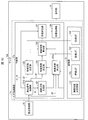
- FIG. 1 is a block diagram illustrating an example of a main configuration of a television 10 on which the noise reduction device 1 (display control device) according to the present embodiment is mounted.
- FIG. 2 is a diagram illustrating the television 10 (display device, television receiver). It is an external view which shows an example of the external appearance of a machine.
- the noise reduction device 1 controls the display of an image on the television 10. Specifically, the noise reduction device 1 reduces color noise of an image displayed on the television 10. More specifically, the noise reduction device 1 determines pixels for reducing noise in a still image (hereinafter referred to as a frame) that constitutes video content (for example, a received broadcast program) to be displayed on the television 10. The threshold value corresponding to the luminance of the frame is determined. Then, the color noise is reduced by reducing the saturation of the pixel having the luminance smaller than the determined threshold while maintaining the luminance.
- a frame that constitutes video content (for example, a received broadcast program)
- the noise reduction device 1 is described as being mounted on the television 10 shown in FIG.
- the device on which the noise reduction device 1 is mounted is not limited to a television receiver.
- the noise reduction device 1 is mounted on, for example, a playback device (player) that plays back recorded video, a display device (monitor) that does not have a tuner, a set-top box, a tuner for receiving cable TV broadcasting, satellite broadcasting, or the like. May be.
- the playback device may be integrated with a recording device that records a broadcast program.
- FIG. 1 is a figure which shows only the member with high relevance to this invention among the members with which the television 10 is provided. Further, illustration and detailed description of members having low relevance to the present invention are omitted.
- the television 10 includes a broadcast receiving unit 11 that receives a broadcast stream, a control unit 12 that controls and controls each unit of the television 10, a storage unit 13 that stores various data used in the television 10, and A display unit 14 for displaying the video of the broadcast program is provided.
- the broadcast receiving unit 11 receives a broadcast stream including a broadcast program broadcast by, for example, terrestrial digital broadcasting or satellite broadcasting.
- the broadcast receiving unit 11 is configured by an antenna and a tuner, for example.
- the control unit 12 includes a broadcast signal control unit 121, a luminance distribution generation unit 122 (maximum value specifying unit), a luminance coefficient determination unit 123, a saturation coefficient determination unit 124, a hue coefficient determination unit 125, and a calculation coefficient calculation unit 126. , A saturation correction unit 127 (saturation changing unit), and a video processing unit 128 are included. Further, the storage unit 13 stores luminance coefficient determination information 131, a luminance lookup table 132, a saturation lookup table 133, and a hue lookup table 134. In FIG. 1, the lookup table is denoted as LUT, and in the following description, the lookup table is denoted as LUT.
- the broadcast signal control unit 121 outputs information of each frame of the broadcast program included in the received broadcast stream to each unit of the control unit 12. Specifically, the broadcast signal control unit 121 outputs luminance information d1 indicating the luminance of each pixel of the frame and color difference information d2 indicating the saturation and hue of each pixel of the frame to the saturation correction unit 127. Also, the broadcast signal control unit 121 outputs the luminance information d1 to the luminance distribution generation unit 122. The broadcast signal control unit 121 also outputs the color difference information d2 to the saturation coefficient determination unit 124 and the hue coefficient determination unit 125.
- the broadcast signal control unit 121 acquires color component information (specifically, the values of the red component, green component, and blue component of each pixel of the frame), the broadcast component control unit 121 converts the color component information into luminance information d1 and color difference information. It converts into d2, and outputs it to each part of the control part 12 mentioned above.
- a known technique can be used as a method of converting the color component information into the luminance information d1 and the color difference information d2.
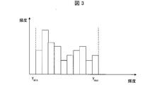
- the luminance distribution generation unit 122 generates a luminance distribution (luminance histogram) of the frame based on the acquired luminance information d1. For example, the luminance distribution generation unit 122 generates the luminance distribution shown in FIG. FIG. 3 is a diagram illustrating an example of the luminance distribution generated by the luminance distribution generation unit 122. Note that the luminance distribution generated by the luminance distribution generation unit 122 is not limited to the example of FIG. In addition, the luminance distribution generation unit 122 refers to the generated luminance distribution, and specifies a frame luminance maximum value Y max that is the maximum luminance value in the received frame and a frame luminance minimum value Y min that is the minimum value. And output to the luminance coefficient determination unit 123.
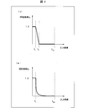
- the luminance coefficient determination unit 123 determines a luminance coefficient A Y (first coefficient) that is a coefficient corresponding to the luminance of the frame received by the television 10. Specifically, the luminance coefficient determination unit 123 first reads the luminance LUT 132 from the storage unit 13. The luminance LUT 132 stores information indicating the function of the luminance coefficient AY with respect to the luminance, for example, the function illustrated in FIG. FIG. 4 is a diagram illustrating an example of a function stored in the luminance LUT 132.
- the luminance factor A Y is maximum 1 in the range of brightness from 0 cd / m 2 to Y 1 cd / m 2. It takes 0 and decreases linearly in the range from Y 1 cd / m 2 to Y 2 cd / m 2, and becomes 0 in the range from Y 2 cd / m 2 .
- the numerical range considered low luminance in reducing target frame noise i.e., Y 2 cd / m 2 from 0 cd / m 2, hereinafter, a range of low brightness This is because the purpose is to reduce the color noise of the pixels included. More specifically, noise reduction device 1 according to this embodiment considers the range of 0 cd / m 2 to Y 1 cd / m 2 and noise reduction range, the saturation of the pixel to zero.
- the luminance coefficient A Y is a coefficient that decreases as the luminance increases in a range from Y 1 cd / m 2 to Y 2 cd / m 2 (a predetermined luminance range).
- the noise reduction device 1 regards the range from Y 1 cd / m 2 to Y 2 cd / m 2 as the adjustment range, and decreases the luminance coefficient A Y in a linear function as the luminance value increases. By providing this adjustment range, it is possible to suppress an abrupt change in saturation between a pixel whose saturation is 0 and a pixel whose saturation is not reduced.
- the luminance coefficient determination unit 123 determines the value Y 1 and the value Y 2 in the luminance LUT 132, and determines the luminance coefficient A Y for each luminance of the frame. Specifically, the luminance coefficient determination unit 123 reads the luminance coefficient determination information 131 from the storage unit 13, and defines a range of low luminance in the frame from the frame luminance maximum value Y max and the read luminance coefficient determination information 131. To do.
- the luminance coefficient determination information 131 includes a low luminance range determination coefficient B, noise reduction range determination information, and adjustment range determination information.
- the low luminance range determination coefficient B is a coefficient for determining the noise reduction range and the adjustment range.
- the low luminance range determination coefficient B is a coefficient for defining a low luminance range in the frame.
- the low luminance range determination coefficient B 0.005 will be described, but the present invention is not limited to this example.
- Noise reduction range determination information is information for determining the value Y 1.
- the noise reduction range determination information may be information that can determine the value Y 1 , It is not limited to this example.
- Adjustment range determination information is information for determining the value Y 2.
- the adjustment range determination information may be information that can determine the value Y 2 , and this example It is not limited to.
- the luminance coefficient determination unit 123 determines the value Y 1 as 0.5 cd / m 2 and sets the value Y 2 as 1 cd / m 2 . decide. Then, the luminance coefficient determination unit 123 determines the luminance coefficient A Y for the luminance of each pixel of the received frame by substituting the value Y 1 , the value Y 2 , and the frame luminance maximum value Y max into the luminance LUT 132. As shown in FIG. 4 (a), the brightness coefficient A Y according to the present embodiment, it becomes 0 for the pixel value Y 2 or more brightness.
- the value Y 2 of the present embodiment is a value indicating the 1% intensity with respect to the frame luminance maximum value Y max. That is, the luminance coefficient determination unit 123 according to the present embodiment sets the luminance coefficient AY of pixels having a luminance equal to or higher than a predetermined ratio to the frame luminance maximum value Ymax to zero. Although details will be described later, the noise reduction apparatus 1 does not reduce the saturation of pixels with the luminance coefficient AY being zero. In other words, the noise reduction device 1 includes a pixel having a value Y 2 is smaller than the luminance reducing saturation. That is, the luminance coefficient determination unit 123 can also be expressed as determining a first threshold value (value Y 2 , first value) according to the luminance of the image for determining a pixel for reducing noise.
- the luminance coefficient determination unit 123 further determines a second threshold value (value Y 1 , second value) in the luminance of the image, and the noise reduction device 1 is included in the range of the luminance from 0 to the value Y 1. saturation and 0 for pixels, a pixel whose luminance is within the range from the value Y 1 of the value Y 2 is to reduce the degree of decrease of the saturation as the brightness is increased, and can be expressed.
- the luminance coefficient determination unit 123 outputs the determined luminance coefficient AY to the calculation coefficient calculation unit 126.
- the function stored in the luminance LUT 132 is not limited to the example of FIG.
- a period from a value Y 1 to the value Y 2 may be a function which decreases quadratically. That is, in the function stored in the luminance LUT 132, the range from the value Y 1 to the value Y 2 may be any attenuation function.
- the attenuation function is a function other than a linear function, it is desirable to configure the noise reduction device 1 so that an arithmetic processor for preparing the attenuation function can be used.
- the function stored in the luminance LUT 132 may be a function in which the luminance coefficient decreases stepwise as the luminance increases (for example, the luminance coefficient decreases as the luminance increases by 2).
- the luminance coefficient determination unit 123 may set the luminance coefficient AY to 0 regardless of the luminance of the pixel of the frame when the frame luminance minimum value Ymin exceeds a predetermined value (for example, 5 cd / m 2 ). As a result, when the frame is generally bright, noise reduction processing based on luminance is not performed, so that a situation where saturation is excessively reduced can be prevented.
- the Saturation factor determination unit 124 determines the saturation factor A S is a coefficient corresponding to the saturation of the frame in which the television 10 has received. Specifically, when the saturation coefficient determination unit 124 acquires the color difference information d2 from the broadcast signal control unit 121, first, it calculates the saturation S of each pixel. Specifically, the color difference information d2 acquired by the saturation coefficient determination unit 124 includes a blue system color difference C b indicating the saturation and hue of the blue system, and a red system color difference C r indicating the saturation and hue of the red system. And are included.
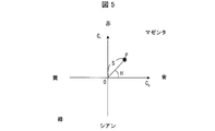
- the relationship between the saturation S and the hue H, and the blue system color difference Cb and the red system color difference Cr will be described with reference to FIG. FIG.
- FIG. 5 is a plane coordinate showing a relationship between the saturation S and the hue H, and the blue system color difference Cb and the red system color difference Cr .
- the saturation S of a certain color P (C b , C r ) is expressed by the origin O and the point P (in other words, the line segment length of the OP) the distance between the angle formed between a straight line passing through
- This arithmetic expression is an example, and the method of calculating the saturation S is not limited to this example.
- are absolute values of the blue system color difference C b and the red system color difference C r , respectively.
- the saturation S is for, the higher the absolute value of the bluish color difference C b and reddish color difference C r is large, the method of calculating the saturation S is as long as it performs operations such as can show this relationship Good.
- the saturation coefficient determination unit 124 reads the saturation LUT 133 from the storage unit 13.
- the saturation LUT133 is stored information indicating a function of the saturation factor A S for saturation S, for example, a function shown in FIG. 6 is stored.
- FIG. 6 is a diagram illustrating an example of functions stored in the saturation LUT 133.
- Saturation factor determination unit 124 the calculated saturation S substituted into the function number, to determine the saturation factor A S for saturation of each pixel of the received frame.
- the saturation coefficient determination unit 124 outputs the determined saturation coefficient AS to the calculation coefficient calculation unit 126.
- the function stored in the chroma LUT133 may be any function, such as the value of the saturation factor A S the greater the saturation S of the pixel is large, not limited to the example of FIG. 6.
- the hue coefficient determination unit 125 reads the hue LUT 134 from the storage unit 13.
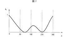
- Hue LUT134 is stored information indicating a function of the hue coefficients A H is for hue H, for example, a function shown in FIG. 7 is stored.
- FIG. 7 is a diagram illustrating an example of functions stored in the hue LUT 134.
- the hue coefficient determination unit 125 substitutes the calculated hue H into the function, and determines the hue coefficient A H for the hue of each pixel of the received frame. In other words, the hue coefficients A H is according to the hue of each pixel of the frame, it can be expressed as a coefficient for each pixel. Then, the hue coefficient determination unit 125 outputs the determined hue coefficient AH to the calculation coefficient calculation unit 126.
- the arithmetic expression for calculating the arithmetic coefficient AT is an example, and the present invention is not limited to this example.
- the calculation coefficient calculation unit 126 outputs the calculated calculation coefficient AT to the saturation correction unit 127.
- the calculation coefficient AT according to the present embodiment is a coefficient proportional to the luminance coefficient AY . That is, the calculation coefficient AT according to the present embodiment increases as the brightness coefficient AY increases.
- the calculation coefficient AT according to the present embodiment includes the saturation coefficient A S determined based on the function (see FIG. 6) stored in the saturation LUT 133 and the function stored in the hue LUT 134 (FIG. 7). it is a coefficient proportional to the hue coefficients a H which is determined based on the reference). That is, the arithmetic coefficient AT according to the present embodiment has a larger value as the saturation is larger, and a larger value as the hue is closer to blue and yellow.
- the saturation correction unit 127 reduces the saturation of the pixels included in the low luminance range among the pixels of the frame.
- the video processing unit 128 includes the blue system color difference C b and the red system color difference C r included in the color difference information d2 acquired from the broadcast signal control unit 121, and the calculation coefficient A T acquired from the calculation coefficient calculation unit 126. from, the corrected (in other words, decreased saturation) calculates bluish color difference C b and reddish color difference C r a is bluish color difference C b 'and reddish color difference C r', respectively.
- the blue system color difference C b ′ and the red system color difference C r ′ are calculated.
- the saturation correction unit 127 outputs the calculated blue system color difference C b ′ and red system color difference C r ′ to the video processing unit 128.
- the saturation correction by the saturation correction unit 127 will be described in detail. Although details will be described later, the video processing unit 128 causes the display unit 14 to display a frame based on the luminance information d1, the blue system color difference C b ′, and the red system color difference C r ′ acquired from the saturation correction unit 127. As described above, the blue system color difference C b ′ and the red system color difference C r ′ are obtained by multiplying the obtained blue system color difference C b and red system color difference C r by a value obtained by subtracting the operation coefficient AT from 1, respectively. Is required.
- the saturation correction unit 127 changes the values of the blue system color difference C b and the red system color difference C r to the blue system color difference C b ′ and the red system color difference C r ′, respectively, and is displayed on the display unit 14. The saturation of each pixel of the frame is changed from the saturation of each pixel of the received frame.
- the calculation coefficient A T is calculated by multiplying the luminance coefficient A Y , the saturation coefficient A S , and the hue coefficient A H. That is, the calculation coefficient A T becomes larger as the values of the luminance coefficient A Y , the saturation coefficient A S , and the hue coefficient A H are larger.
- the calculation coefficient AT is also a value of 0 or more and 1 or less, and similarly (1 -A T ) is also a value between 0 and 1.
- the saturation S (the saturation S of each pixel in the frame displayed on the display unit 14) based on the blue system color difference C b ′ and the red system color difference C r ′ is smaller as the arithmetic coefficient AT is larger.
- the difference from the saturation S of each pixel in the received frame increases (in other words, the greater the luminance coefficient AY , the greater the degree of decrease in saturation S).
- brightness coefficient A Y when the luminance of each pixel is not included in the scope of the low-intensity (range 0 cd / m 2 of Y 2 cd / m 2), the value Becomes 0. That is, for the pixels whose luminance is not included in the low luminance range, the calculation coefficient AT is 0, so that the noise reduction device 1 does not correct the saturation of the pixel (the saturation does not decrease). That is, the noise reduction device 1 according to the present embodiment reduces only the saturation of the pixels included in the low luminance range.
- the luminance information d1 of the received frame is output to the video processing unit 128 as it is. Therefore, the frame displayed on the display unit 14 maintains the luminance of each pixel of the received frame.
- the broadcast signal control unit 121 may output the luminance information d1 to the video processing unit 128 instead of the saturation correction unit 127.
- the hue of each pixel of the frame displayed on the display unit 14 is the one in which the hue H of each pixel of the received frame is maintained.
- the video processing unit 128 causes the display unit 14 to display a frame based on the acquired luminance information d1, the blue system color difference C b ′, and the red system color difference C r ′. As a result, the display unit 14 displays a frame in which the saturation is corrected (the saturation is reduced) in the pixels included in the low luminance range.
- the noise reduction device 1 since the noise reduction device 1 according to the present embodiment reduces the saturation at the low-luminance pixel, it is possible to suppress the occurrence of color noise at the pixel. Also, noise reduction processing can be performed only on pixels that need noise reduction. Further, since the luminance of each pixel is maintained, it is possible to suppress the occurrence of a blurred region or a blackened region due to the luminance reduction.
- FIG. 8 is a flowchart illustrating an example of the flow of noise reduction processing executed by the noise reduction apparatus 1.
- the broadcast signal control unit 121 waits for reception of a broadcast program frame (step S1, hereinafter, “step” is omitted).
- step S1 the broadcast signal control unit 121 outputs the luminance information d1 and the color difference information d2 to the saturation correction unit 127.
- the broadcast signal control unit 121 outputs the luminance information d1 to the luminance distribution generation unit 122.
- the broadcast signal control unit 121 also outputs the color difference information d2 to the saturation coefficient determination unit 124 and the hue coefficient determination unit 125.
- the luminance distribution generation unit 122 generates a luminance distribution using the acquired luminance information d1 (S2). Then, referring to the generated luminance distribution, the frame luminance maximum value Y max and the frame luminance minimum value Y min are specified and output to the luminance coefficient determination unit 123.
- the luminance coefficient determination unit 123 defines a low luminance range in the received frame (S3). Specifically, the luminance coefficient determination unit 123 sets the value Y 1 and the value Y 2 in the function stored in the luminance LUT 132 read from the storage unit 13, the acquired frame luminance maximum value Y max, and the storage unit 13. calculated from the low-luminance range determining coefficients B read, defining the low luminance range (in other words, specific numerical values Y 2). Subsequently, the luminance coefficient determination unit 123 determines the luminance coefficient AY (S4).
- the luminance coefficient A Y with respect to the luminance of each pixel of the received frame.
- the luminance coefficient AY for luminance not included in the low luminance range is zero.
- the luminance coefficient determination unit 123 outputs the determined luminance coefficient AY to the calculation coefficient calculation unit 126.
- the chroma coefficient determining unit 124 determines the saturation factor A S (S5). More specifically, to calculate the saturation S and a bluish color difference C b and reddish color difference C r contained in the color difference information d2 obtained, is stored in the chroma LUT133 read from the storage unit 13 functions, by substituting the calculated saturation S, to determine the saturation factor a S for saturation of each pixel of the received frame.
- the saturation coefficient determination unit 124 outputs the determined saturation coefficient AS to the calculation coefficient calculation unit 126.
- the hue coefficient determining unit 125 determines the hue coefficients A H (S6). Specifically, calculates the hue H and a bluish color difference C b and reddish color difference C r contained in the color difference information d2 obtained, the function stored in the hue LUT134 read from the storage unit 13, and calculates By assigning the hue H, the hue coefficient A H for the hue of each pixel of the received frame is determined.
- the hue coefficient determination unit 125 outputs the determined hue coefficient AH to the calculation coefficient calculation unit 126.
- process of S4, S5, and S6 should just be performed before the process of S7 after the process of S3, The order is not specifically limited. Further, the processes of S4, S5, and S6 may be performed simultaneously.
- the calculation coefficient calculation unit 126 calculates a calculation coefficient AT from the acquired luminance coefficient A Y , saturation coefficient A S , and hue coefficient A H (S7). Then, the calculation coefficient calculation unit 126 outputs the calculated calculation coefficient AT to the saturation correction unit 127.
- the video processing unit 128 displays the corrected frame on the display unit 14 (S9). Specifically, the video processing unit 128 causes the display unit 14 to display a frame based on the acquired luminance information d1, the blue system color difference C b ′, and the red system color difference C r ′. As a result, the display unit 14 displays a frame in which the saturation is corrected (the saturation is reduced) in the pixels included in the low luminance range.
- the low luminance range determination coefficient B included in the luminance coefficient determination information 131 described above is a constant value regardless of the frame luminance maximum value Y max , but the low luminance range determination coefficient B is the frame luminance maximum value Y max. It may be a value according to. Details of this modification will be described with reference to FIG. FIG. 9 is a graph for explaining the low luminance range determination coefficient B that changes in accordance with the frame luminance maximum value Ymax .
- the storage unit 13 of the noise reduction apparatus 1 according to the present modification stores an LUT that stores the function shown in FIG.
- the luminance coefficient determination unit 123 reads the LUT, and specifies a low luminance range determination coefficient B corresponding to the acquired frame luminance maximum value Y max from the illustrated function.
- the function for specifying the low luminance range determination coefficient B is not limited to the illustrated example. However, even when the frame luminance maximum value Y max is large, it is possible to perform the noise reduction process only on pixels that are likely to cause color noise (in other words, pixels having low luminance values). Therefore, as shown in the figure, when the frame luminance maximum value Y max is equal to or greater than a predetermined value, the function is such that the low luminance range determination coefficient B gradually decreases as the frame luminance maximum value Y max increases. desirable.
- FIG. 10 is a block diagram illustrating an example of a main configuration of the television 10a according to the present embodiment.
- the television 10a in other words, the noise reduction device 1a mounted on the television 10a
- the maximum luminance information Maximum Content Light Level
- an appropriate low luminance range is defined for each frame of the content. The details will be described below.
- the television 10 a includes a control unit 12 a instead of the control unit 12.
- the control unit 12a includes a broadcast signal control unit 121a and a luminance coefficient determination unit 123a instead of the broadcast signal control unit 121 and the luminance coefficient determination unit 123, respectively.
- the broadcast signal control unit 121a outputs the maximum luminance information d3 included in the broadcast stream to the luminance coefficient determination unit 123a in addition to the function of the broadcast signal control unit 121 described above.
- the maximum luminance information d3 is information indicating the highest luminance in the content. That is, in the present embodiment, the maximum luminance information d3 is one value for one content.
- the maximum luminance information d3 is information included in the first frame in the content. Therefore, when the broadcast signal control unit 121a acquires the first frame in the content, the broadcast signal control unit 121a outputs the maximum luminance information d3 included in the frame to the luminance coefficient determination unit 123a.
- the maximum luminance information d3 may not be one value for one content.
- the maximum luminance information d3 may be information indicating the highest luminance in each segment when the content is divided into several segments. In this case, the maximum luminance information d3 exists as many as the number of segments for one content. In this case, the maximum luminance information d3 is included in the first frame in each segment.
- the maximum luminance information d3 may be information indicating the highest luminance in each frame.
- the maximum luminance information d3 exists as many as the number of frames for one content.
- the maximum luminance information d3 is included in each frame.
- the maximum luminance information d3 is information indicating the highest luminance in each frame
- the maximum luminance information d3 and the frame luminance maximum value Y max are likely to be the same value.
- the maximum luminance information d3 is a value set on the content transmission side
- the frame luminance maximum value Y max is the highest luminance in the luminance distribution generated in the noise reduction device 1a (that is, reception of content).
- the value may be a different value.
- the maximum luminance information d3 may be expressed as a maximum luminance value MaxCLL.
- the value Y 1 and the value Y 2 are calculated using the calculated low luminance range determination coefficient B ′. Note that a specific calculation method of the value Y 1 and the value Y 2 has been described in the first embodiment, and thus description thereof is omitted here.
- FIG. 11 is a diagram illustrating a difference in a low luminance range according to a difference in a ratio (that is, Y max / Max CLL) between the maximum luminance information d3 (that is, the maximum luminance value MaxCLL) and the frame luminance maximum value Y max . is there.
- the low-luminance range determining factor B 0.005
- the low-luminance range determining coefficients B ' also 0.005
- the arithmetic expression value Y 2 is the same as Embodiment 1
- low The luminance range is a luminance range of 0 to 1% with respect to the frame luminance maximum value Y max .
- the noise reduction device 1a when the frame luminance maximum value Y max is smaller than the maximum luminance in the content, if the low luminance range is a luminance range of 0 to 1% with respect to the frame luminance maximum value Y max , noise reduction is necessary. There is a risk that noise reduction may be performed on pixels that do not have any. Accordingly, the noise reduction device 1a according to the present embodiment further narrows the low luminance range when the frame luminance maximum value Y max is smaller than the maximum luminance in the content. Thereby, noise reduction can be performed only for pixels that need noise reduction. A specific example is shown in FIG. FIG.
- the low luminance range is a luminance of 0 to 0.5% with respect to the frame luminance maximum value Y max . It becomes the range.
- the low luminance range determination coefficient B ′ predetermined ratio
- the low luminance range determination coefficient B ′ is expressed as being small when the difference between the frame luminance maximum value Y max and the maximum luminance value MaxCLL is large, and large when the difference is small. You can also.
- the noise reduction device 1a corrects the low luminance range determination coefficient B according to the ratio (Y max / Max CLL) between the maximum luminance value MaxCLL and the frame luminance maximum value Y max .
- the ratio (Y max / Max CLL) between the maximum luminance value MaxCLL and the frame luminance maximum value Y max .
- the luminance coefficient determination unit 123a described above uses the maximum luminance value MaxCLL to correct the low luminance range determination coefficient B, but the method of using the maximum luminance value MaxCLL is not limited to this example.
- the brightness coefficient determining section 123a has a maximum luminance value MaxCLL, be used in place of the frame luminance maximum value Y max, may calculate the value Y 1 and the value Y 2.
- the noise reduction device 1a replaces the maximum luminance information d3 with the average luminance information (Maximum Frame Average Light Level, hereinafter referred to as the average luminance) indicating the average luminance (average luminance of the content) included in the broadcast stream.
- the information may be referred to as an average luminance value MaxFALL), and an appropriate low luminance range may be defined for each frame of content.
- the specific processing executed by the luminance coefficient determination unit 123a in this case is the same as the processing described above except that the maximum luminance value MaxCLL is replaced with the average luminance value MaxFALL in the processing described above. Description is omitted.
- the noise reduction apparatus 1a replaces the maximum brightness information d3 with the content creation maximum brightness information indicating the maximum brightness on the monitor (display device) used when the content creator creates the content, which is included in the broadcast stream.
- Luminance) may be used and the suitable low-intensity range may be defined for every frame of a content. Note that the specific processing executed by the luminance coefficient determination unit 123a in this case is the same as the processing described above, except that the maximum luminance value MaxCLL is replaced with the value in the maximum luminance information at the time of content creation in the processing described above. Therefore, explanation here is omitted.
- FIG. 12 is a block diagram illustrating an example of a main configuration of the television 10b according to the present embodiment.
- the television 10b (in other words, the noise reduction device 1b mounted on the television 10b) is in response to an input signal input by the user using the remote controller (hereinafter referred to as the remote controller 20) of the television 10b (in other words, in other words).
- the remote controller 20 the remote controller of the television 10b (in other words, in other words).
- the remote controller 20 the remote controller of the television 10b (in other words, in other words).
- the remote controller 20 the remote controller of the television 10b (in other words, in other words).
- the television 10 b includes a control unit 12 b instead of the control unit 12.
- the television 10b further includes a remote control receiver 15 that receives a signal transmitted from the remote controller 20 (hereinafter referred to as a remote control signal).
- the control unit 12b includes a broadcast signal control unit 121b, a luminance coefficient determination unit 123b, and a calculation coefficient calculation instead of the broadcast signal control unit 121, the luminance coefficient determination unit 123, the calculation coefficient calculation unit 126, and the video processing unit 128. A part 126b and a video processing part 128b are included. Further, the control unit 12b newly includes a remote control signal control unit 129.
- the broadcast signal control unit 121b has the same configuration as the broadcast signal control unit 121a described in the second embodiment, and a description thereof is omitted here.
- the remote control signal control unit 129 acquires the remote control signal from the remote control reception unit 15, the remote control signal control unit 129 identifies an operation instruction included in the remote control signal and outputs it to the luminance coefficient determination unit 123b or the calculation coefficient calculation unit 126b. Specifically, when the specified operation instruction is a low-luminance range determination coefficient B correction instruction d4, remote control signal control section 129 outputs correction instruction d4 to luminance coefficient determination section 123b. Further, when the specified operation instruction is the correction instruction d5 for the calculation coefficient AT , the remote control signal control unit 129 outputs the correction instruction d5 to the calculation coefficient calculation unit 126b.
- the remote control signal control unit 129 displays a UI for causing the identified operation instruction to display a user interface (hereinafter referred to as UI) for correcting the low-luminance range determination coefficient B and the calculation coefficient AT on the display unit 14. If the instruction is d6, the UI display instruction d6 is output to the video processing unit 128b.
- UI user interface
- the luminance coefficient determination unit 123b differs from the luminance coefficient determination unit 123 in the following points. That is, the luminance coefficient determination unit 123b corrects the read low luminance range determination coefficient B according to the acquired correction instruction d4. For example, when the correction instruction d4 is an instruction for doubling the low luminance range determination coefficient, the luminance coefficient determination unit 123b reduces the low luminance range determination coefficient B "by doubling the low luminance range determination coefficient B according to the instruction. And the luminance coefficient AY is determined based on the low luminance range determination coefficient B ′′.
- the luminance coefficient determination unit 123b uses the acquired maximum luminance value MaxCLL and the maximum frame luminance value Y max as in the luminance coefficient determination unit 123a described in the second embodiment, and calculates the low luminance range determination coefficient B ′. It may be configured to correct. In the case of this example, the luminance coefficient determination unit 123b further corrects according to the correction instruction d4 that acquired the low luminance range determination coefficient B ′.
- the correction instruction d4 may be an instruction for changing (correcting) the low luminance range, and the value corrected by the instruction is not limited to the low luminance range determination coefficient B.
- the luminance coefficient determination unit 123b may correct the maximum luminance value MaxCLL according to the correction instruction d4.
- the calculation coefficient calculation unit 126b is different from the calculation coefficient calculation unit 126 in the following points. That is, the calculation coefficient calculation unit 126b corrects the calculated calculation coefficient AT according to the acquired correction instruction d5. For example, if the correction instruction d5 was 0.5 multiply instruction calculation coefficients A T, the calculation coefficient calculation unit 126b, the arithmetic coefficient calculation coefficient was 0.5 times the operational coefficient A T in response to the instruction A T 'Is calculated, and this calculation coefficient calculation coefficient A T ' is output to the saturation correction unit 127.
- the video processing unit 128b differs from the video processing unit 128 in the following points. That is, when acquiring the UI display instruction d6 from the remote control signal control unit 129, the video processing unit 128b causes the display unit 14 to display a UI for correcting the low-luminance range determination coefficient B and the calculation coefficient AT .
- the UI is not particularly limited as long as it can accept correction of the low luminance range determination coefficient B and the calculation coefficient AT .
- the UI may be as shown in FIG.
- FIG. 13 is a diagram illustrating an example of a UI displayed on the display unit 14.
- the video processing unit 128 b may cause the display unit 14 to display a UI 141 that receives an input for correcting the low luminance range determination coefficient B (or the maximum luminance value MaxCLL).
- the UI 141 is a slider in which the handle portion 411 (circular portion of the UI 141) moves on the slider portion 412 (rectangular portion of the UI 141) in response to the user operating the remote controller 20.
- the UI 141 indicates that the handle portion 411 corresponds to the lower limit display 413 (text “0”) of the slider portion 412 (ie, (a) in FIG. 13) in response to the user operating the remote controller 20.
- the lower limit display 413 is a display indicating the lower limit position of the slider portion 412
- the upper limit display 414 is a display indicating the upper limit position of the slider portion 412.
- the display unit 14 displays a text “Dark part noise reduction” indicating a process executed when the user operates the remote controller 20 when the screen shown in FIG. 13A is displayed. Yes.
- the remote control signal control unit 129 corresponds to the lower limit display 413 (text “0”) on the slider unit 412, in which the handle unit 411 of the UI 141 is from the left end to the right end in FIG. 13A of the slider unit 412.
- the low luminance range determination coefficient B is corrected according to the position.
- An instruction to that effect is output to the luminance coefficient determination unit 123b as a correction instruction d4.
- the remote control signal control unit 129 changes the amount of change in the low luminance range determination coefficient B with respect to the value indicating the position of the handle unit 411 in the slider unit 412 stored in the storage unit 13 (in other words, low luminance A LUT (not shown) storing a function of a value indicating how many times the range determination coefficient B is multiplied is read out. Then, a value indicating the position of the handle portion 411 in the slider portion 412 is substituted into the function to specify the amount of change in the low luminance range determination coefficient B.
- the function is, for example, a value indicating that the position of the handle portion 411 in the slider portion 412 is a position corresponding to the lower limit display 413 (text “0”) in the slider portion 412, and the low luminance range determination coefficient B
- the change amount of the low luminance range determination coefficient B is 0 when the change amount of the handle portion 411 is a value indicating that the position of the handle portion 411 corresponds to the upper limit display 414 (text “+10”) in the slider portion 412.
- a linear function that doubles the amount may be used.
- the function described here is an example, and the function is not limited to this example.
- the video processing unit 128b corrects the UI 142 that receives an input for correcting the low luminance range determination coefficient B (or the maximum luminance value MaxCLL), and the arithmetic coefficient AT .
- a UI 143 that accepts an input for performing the input may be displayed on the display unit 14.
- the UI 142 and the UI 143 are described as being sliders in which the handle portion 411 moves to any one of 11 positions in the slider portion 412 in response to the user operating the remote controller 20 in the same manner as the UI 141 described above. It is not limited to this example.
- the UI 142 includes the text “narrow” as the lower limit display 413 and the text “wide” as the upper limit display 414.
- the UI 142 further includes an intermediate display 415 (text “middle”) indicating a position corresponding to the center of the slider portion 412.
- the UI 143 includes the text “small” as the lower limit display 413, and includes the text “large” as the upper limit display 414.
- the UI 143 includes the text “medium” as the intermediate display 415.
- the display unit 14 includes texts “reduction area” and “reduction amount” that indicate processing executed when the user operates the remote controller 20 when the screen shown in FIG. 13B is displayed. Are displayed adjacent to UI 142 and UI 143, respectively.
- the remote control signal control unit 129 corresponds to the lower limit display 413 (the text “narrow”) on the slider unit 412 where the handle unit 411 of the UI 142 is from the left end to the right end in FIG. 13B of the slider unit 412.
- the low luminance range determination coefficient B is corrected according to the position. Is output to the luminance coefficient determination unit 123b as a correction instruction d4. This process is the same as the process performed when the handle portion 411 of the UI 141 described above is acquired as a remote control signal that the handle portion 411 of the UI 141 has moved on the slider portion 412, and thus the description thereof is omitted here.
- the remote control signal control unit 129 changes the handle portion 411 of the UI 143 from the left end to the right end in FIG. 13B of the slider portion 412, in other words, the lower limit display 413 (text “small”) on the slider portion 412.
- the arithmetic coefficient AT is corrected according to the position. Is output to the calculation coefficient calculation unit 126 as a correction instruction d5.
- the remote control signal control unit 129 changes the amount of change in the operation coefficient AT with respect to the value stored in the storage unit 13 and indicating the position of the handle unit 411 in the slider unit 412 (in other words, the operation coefficient A T LUT (not shown) storing a function of a value indicating how many times is multiplied) is read. Then, a value indicating the position of the handle portion 411 in the slider portion 412 is substituted into the function, and the change amount of the calculation coefficient AT is specified. For example, when the function is a value indicating that the position of the handle unit 411 in the slider unit 412 corresponds to the lower limit display 413 (text “small”) in the slider unit 412, the change in the calculation coefficient AT is performed.
- the amount of change in the calculation coefficient AT is 0. It may be a linear function that becomes 1 time.
- the function described here is an example, and the function is not limited to this example.
- the remote control signal control unit 129 may be configured to output the remote control signal acquired from the remote control reception unit 15 to the luminance coefficient determination unit 123b, the calculation coefficient calculation unit 126b, or the video processing unit 128b as it is.
- the remote control signal control unit 129 determines the output destination of the acquired remote control signal and outputs the remote control signal to the determined output destination.
- the luminance coefficient determination unit 123b and the calculation coefficient calculation unit 126b correct the low luminance range determination coefficient B or the calculation coefficient AT according to the remote control signal.
- the video processing unit 128b causes the display unit 14 to display a UI corresponding to the remote control signal.
- the remote controller 20 and the remote control receiver 15 are described as examples of members that receive user input operations.
- members that receive user input operations are not limited to this example.
- a physical button provided on the television 10b or a touch panel provided so as to be superimposed on the display unit 14 may be used.
- the remote controller 20 may have only a physical button as shown in FIG. 13, or may have a touch panel in addition to the physical button or instead of the physical button.
- the television 10b may allow the user to select a content display mode and correct the low luminance range determination coefficient B or the maximum luminance value MaxCLL in accordance with the display mode selected by the user.
- the video processing unit 128b may cause the display unit 14 to display a UI for allowing the user to select a content display mode.
- the UI is not particularly limited as long as the user can select a content display mode.
- the UI may be as shown in FIG.
- FIG. 14 is a diagram illustrating another example of a UI displayed on the display unit 14. In this modification, an example in which the maximum luminance value MaxCLL is corrected will be described.
- the UI 144a, UI 144b, and UI 144c shown in FIG. 14 are UIs for accepting a change in content display mode.
- UI 144 when it is not necessary to distinguish between the UI 144a, the UI 144b, and the UI 144c, they are referred to as UI 144.
- the display unit 14 displays a text “select display mode” indicating a process executed when the user operates the remote controller 20 when the screen shown in FIG. 14 is displayed.
- “Dynamic mode” is a mode in which video processing is performed so that content is displayed vividly (specifically, the saturation of each pixel is increased). This mode is suitable for video images.
- “Movie mode” is a mode in which video processing is performed so as to suppress the vividness of the content (specifically, the saturation of each pixel is lowered), and this mode is suitable when the content is a movie or the like. It is.
- the “standard mode” is a mode in which video processing corresponding to content is not performed on the television 10b.
- the content display mode described here is an example, and the content display mode is not limited to this example.
- the remote control signal control unit 129 When the remote control signal control unit 129 acquires the remote control signal indicating which display mode is selected, the amount of change in the maximum luminance value MaxCLL (in other words, how many times the maximum luminance value MaxCLL is increased) according to the acquired remote control signal. Change the value). Specifically, when a remote control signal indicating that the “standard mode” has been selected is acquired, the remote control signal control unit 129 sends a correction instruction d4 for making the change amount of the maximum luminance value MaxCLL to 1 to the luminance coefficient determination unit 123b. Output. Note that when “standard mode” is selected, the maximum luminance value MaxCLL does not change, so the remote control signal control unit 129 may be configured not to output the correction instruction d4.
- the remote control signal control unit 129 When the remote control signal indicating that the “dynamic mode” is selected is acquired, the remote control signal control unit 129 outputs a correction instruction d4 for increasing the change amount of the maximum luminance value MaxCLL by 1.5 times to the luminance coefficient determination unit 123b.
- the dynamic mode is a mode in which video processing is performed so as to increase the saturation of each pixel, so that there is a high possibility that color noise is enhanced. That is, as described above, the maximum luminance value MaxCLL is multiplied by 1.5 to expand the low luminance range (that is, the range in which the saturation is reduced), so that the color noise is caused by the “dynamic mode”. Color noise can be suppressed for pixels that are likely to occur (in other words, pixels that are newly included in the low luminance range by correcting the maximum luminance value MaxCLL).
- the remote control signal control unit 129 When a remote control signal indicating that “movie mode” has been selected is acquired, the remote control signal control unit 129 outputs a correction instruction d4 for increasing the change amount of the maximum brightness value MaxCLL to 0.5 times to the brightness coefficient determination unit 123b. To do. This is a mode in which the movie mode performs video processing so as to lower the saturation of each pixel. Therefore, if the low luminance range is not corrected, the saturation is reduced even for pixels that do not require noise reduction. This is because there is a risk of losing. In other words, as described above, the maximum luminance value MaxCLL is multiplied by 0.5 to reduce the low luminance range (that is, the range in which the saturation is reduced), so that overcorrection in the content can be prevented. Note that the amount of change in the maximum luminance value MaxCLL described here is an example, and is not limited to this example.
- the luminance coefficient determination unit 123, the luminance coefficient determination unit 123a, and the luminance coefficient determination unit 123b (hereinafter, referred to as the luminance coefficient determination unit 123 when there is no need to distinguish between them) according to each embodiment described above according to the content
- the low luminance range determination coefficient B or the maximum luminance value MaxCLL may be corrected.
- the luminance coefficient determination unit 123 acquires information (for example, a movie, a sports broadcast, a drama, etc.) indicating the type of content from the broadcast signal control unit 121, and the low luminance range determination coefficient B according to the information.
- the maximum luminance value MaxCLL is corrected.
- the maximum luminance value MaxCLL is multiplied by 0.5.
- the maximum luminance value MaxCLL is multiplied by 1.5.
- the luminance coefficient determination unit 123 may acquire information indicating the type of content from an EPG (Electronic Program Guide).
- the calculation coefficient calculation unit 126 and the calculation coefficient calculation unit 126b (hereinafter referred to as the calculation coefficient calculation unit 126 when there is no need to distinguish them) according to each of the embodiments described above are the luminance coefficient A Y , saturation
- the calculation coefficient AT is calculated using the coefficient A S and the hue coefficient A H
- the present invention is not limited to this example.
- the calculation coefficient calculation unit 126 may determine the calculation coefficient AT using at least the luminance coefficient AY . When only the luminance coefficient AY is used, the calculation coefficient calculation unit 126 outputs the acquired luminance coefficient AY to the saturation correction unit 127 as the calculation coefficient AT .
- control blocks of noise reduction apparatuses 1, 1a, and 1b may be realized by a logic circuit (hardware) formed in an integrated circuit (IC chip) or the like. However, it may be realized by software using a CPU (Central Processing Unit).
- a logic circuit hardware
- IC chip integrated circuit
- CPU Central Processing Unit
- the noise reduction devices 1, 1 a, and 1 b include a CPU that executes instructions of a program that is software that realizes each function, and a ROM (in which the program and various data are recorded so as to be readable by a computer (or CPU)) Read Only Memory) or a storage device (these are referred to as "recording media"), a RAM (Random Access Memory) for expanding the program, and the like.
- a computer or CPU
- a “non-temporary tangible medium” such as a tape, a disk, a card, a semiconductor memory, a programmable logic circuit, or the like can be used.
- the program may be supplied to the computer via an arbitrary transmission medium (such as a communication network or a broadcast wave) that can transmit the program.
- a transmission medium such as a communication network or a broadcast wave
- the present invention can also be realized in the form of a data signal embedded in a carrier wave in which the program is embodied by electronic transmission.
- the display control device (noise reduction device 1) according to aspect 1 of the present invention is a pixel having a first value corresponding to the luminance of an image to be displayed and smaller than the luminance corresponding to the first value. Is provided with a saturation changing unit (saturation correcting unit 127) that reduces the saturation while maintaining the luminance.
- the saturation is reduced for a pixel whose luminance is lower than the first value.
- the saturation is not reduced for pixels having a luminance equal to or higher than the first value. Therefore, it is possible to reduce the saturation only in the low luminance region of the image.
- the saturation of the pixels in the low luminance region decreases, the color difference from surrounding pixels becomes inconspicuous. Therefore, the color noise generated in the low luminance area of the image becomes inconspicuous. Therefore, the color noise generated in the low luminance area of the image can be made inconspicuous, and as a result, the color noise can be reduced.
- the luminance of the pixel whose saturation is reduced is maintained, so that the color noise can be reduced without reducing the information amount of the image.
- the display control apparatus further includes a maximum value specifying unit (brightness distribution generation unit 122) that specifies the maximum value of the luminance of the image in the above aspect 1, and the first value is The value may be a predetermined ratio with respect to the maximum value.
- a maximum value specifying unit (brightness distribution generation unit 122) that specifies the maximum value of the luminance of the image in the above aspect 1, and the first value is The value may be a predetermined ratio with respect to the maximum value.
- the first value is a value that is a predetermined ratio with respect to the maximum luminance value of the image.
- the display control apparatus is the display control apparatus according to aspect 2, wherein the predetermined ratio includes a maximum value of the luminance of the image and a maximum value of the luminance of the content set in advance for the content including the image.
- the difference may be small when the difference is large, and may be large when the difference is small.
- the predetermined ratio is small when the difference between the maximum value of the luminance of the image and the maximum value of the luminance of the content is large, and is large when the difference is small. Accordingly, depending on whether the noise reduction target image is a dark scene image or a bright scene image in the content, the noise reduction target pixel (in other words, the saturation reduction target pixel) is selected. Can be changed. Thereby, it is possible to perform optimum noise reduction in the image.
- the predetermined ratio may be changed according to a user operation.
- the predetermined ratio is changed according to the user operation, it is possible to change the pixel of the noise reduction target (in other words, the saturation reduction target) according to the user operation. As a result, it is possible to make the pixel targeted for noise reduction desirable for the user.
- the display control device may cause the display device to display a user interface for changing the predetermined ratio in aspect 4 above.
- the user interface for changing the predetermined ratio is displayed on the display device, the user can check the degree of change of the predetermined ratio. Therefore, it is possible to realize a display control device that is easy for the user to use.
- the display control device is the display control device according to any one of the aspects 1 to 5, wherein the saturation changing unit has a luminance value from 0 to a value corresponding to the luminance of the image.
- the saturation of the pixels included in the range of the second value having a smaller value is set to 0, and the luminance is decreased from the second value to the range of the pixels included in the range of the first value. You may make it small, so that it becomes large.
- the saturation is 0 for the pixels included in the range of the brightness from 0 to the second value
- the lower brightness area in other words, the color noise is present in the low brightness area.
- Color noise in a more conspicuous area can be appropriately reduced.
- the degree of decrease in saturation is reduced as the luminance increases, so that the luminance is particularly high among pixels having a small difference in luminance. It is possible to suppress a rapid change in saturation between pixels having values around the value of.
- the saturation changing unit may increase the degree of decrease in saturation for pixels whose hue is closer to blue.
- the color noise is more noticeable as the hue is closer to blue.
- the degree of decrease in saturation is increased as the pixel has a hue closer to blue. Therefore, the color noise that is more conspicuous can be made inconspicuous, so that more effective color noise reduction can be realized.
- the saturation changing unit may increase the degree of decrease in saturation as the pixel has higher saturation.
- the display device (television 10) according to aspect 9 of the present invention may include the display control device according to any one of aspects 1 to 8.
- the television receiver (television 10) according to aspect 10 of the present invention may include the display control device according to any one of aspects 1 to 8.
- the control method of the display control device is the first value corresponding to the luminance of the image to be displayed, and the luminance of the pixel having a luminance smaller than the luminance corresponding to the first value.
- the display control apparatus may be realized by a computer.
- the display control apparatus is operated on each computer by causing the computer to operate as each unit (software element) included in the display control apparatus.
- the display control device control program to be realized and a computer-readable recording medium on which the control program is recorded also fall within the scope of the present invention.
- Noise reduction device 10
- Television display device, television receiver
- luminance distribution generation unit maximum value specifying unit
- Saturation Correction Unit Saturation Change Unit
Abstract
The present invention reduces color noise in a low-brightness region of an image without decreasing the information amount of the image.
A noise reduction device (1) is provided with a saturation correction unit (127) which, regarding a pixel having brightness lower than brightness corresponding to a first value that corresponds to the brightness of an image to be displayed on a television (10), decreases saturation while maintaining the brightness.
Description
本発明は、表示させる画像の色ノイズを低減させる表示制御装置などに関する。
The present invention relates to a display control device for reducing color noise of an image to be displayed.
近年、テレビジョン受像機(テレビ)などの表示装置に表示する画像(映像)の信号に関して、低輝度から高輝度まで豊富な情報量を有するHDR(High Dynamic Range)信号が規格化された。しかしながら、このHDR信号に基づく画像を表示装置に忠実に表示した場合、画像の低輝度領域での色ノイズの発生が問題となる。
In recent years, HDR (High Dynamic Range) signals having an abundant amount of information from low luminance to high luminance have been standardized for image (video) signals displayed on a display device such as a television receiver (television). However, when an image based on this HDR signal is faithfully displayed on a display device, the occurrence of color noise in the low luminance region of the image becomes a problem.
以前より、平均化フィルタ等を用いて表示装置に表示する画像(映像)のノイズを低減する技術はある(例えば、下記特許文献1および特許文献2参照)が、これらの従来技術では、画像の情報量が低下し、画像がぼやけたり、ディテール感が喪失したりするという問題がある。
There has been a technique for reducing noise of an image (video) displayed on a display device using an averaging filter or the like (see, for example, Patent Document 1 and Patent Document 2 below). There is a problem in that the amount of information decreases, the image is blurred, and the feeling of detail is lost.
本発明は、前記の問題点に鑑みてなされたものであり、その目的は、画像の情報量を低下させることなく、画像の低輝度領域での色ノイズを低減する表示制御装置などを実現することにある。
The present invention has been made in view of the above-described problems, and an object of the present invention is to realize a display control device that reduces color noise in a low-brightness area of an image without reducing the amount of information of the image. There is.
上記の課題を解決するために、本発明の一態様に係る表示制御装置は、表示させる画像の輝度に応じた第1の値であって、該第1の値に応じた輝度よりも小さい輝度を有する画素について、輝度を維持しながら彩度を減少させる彩度変更部を備える。
In order to solve the above-described problem, a display control device according to one embodiment of the present invention has a first value corresponding to the luminance of an image to be displayed, and a luminance smaller than the luminance corresponding to the first value. A saturation changing unit that reduces the saturation while maintaining the luminance.
また、上記の課題を解決するために、本発明の一態様に係る表示制御装置の制御方法は、表示させる画像の輝度に応じた第1の値であって、該第1の値に応じた輝度よりも小さい輝度を有する画素について、輝度を維持しながら彩度を減少させる彩度変更ステップを含む。
In order to solve the above-described problem, a control method for a display control device according to one embodiment of the present invention is a first value corresponding to the luminance of an image to be displayed, and the first value corresponds to the first value. For a pixel having a luminance smaller than the luminance, a saturation changing step for decreasing the saturation while maintaining the luminance is included.
本発明の一態様によれば、画像の情報量を低下させることなく、画像の低輝度領域での色ノイズを低減することができるという効果を奏する。
According to one aspect of the present invention, there is an effect that it is possible to reduce color noise in a low luminance region of an image without reducing the amount of information of the image.
〔実施形態1〕
以下、本発明の実施形態1について、図1から図9に基づいて詳細に説明する。Embodiment 1
Hereinafter,Embodiment 1 of the present invention will be described in detail with reference to FIGS. 1 to 9.
以下、本発明の実施形態1について、図1から図9に基づいて詳細に説明する。
Hereinafter,
(本発明の概要)
まず、本発明の概要について、図1および図2に基づいて説明する。図1は、本実施形態に係るノイズ低減装置1(表示制御装置)が搭載されたテレビ10の要部構成の一例を示すブロック図であり、図2は、テレビ10(表示装置、テレビジョン受像機)の外観の一例を示す外観図である。 (Outline of the present invention)
First, the outline | summary of this invention is demonstrated based on FIG. 1 and FIG. FIG. 1 is a block diagram illustrating an example of a main configuration of atelevision 10 on which the noise reduction device 1 (display control device) according to the present embodiment is mounted. FIG. 2 is a diagram illustrating the television 10 (display device, television receiver). It is an external view which shows an example of the external appearance of a machine.
まず、本発明の概要について、図1および図2に基づいて説明する。図1は、本実施形態に係るノイズ低減装置1(表示制御装置)が搭載されたテレビ10の要部構成の一例を示すブロック図であり、図2は、テレビ10(表示装置、テレビジョン受像機)の外観の一例を示す外観図である。 (Outline of the present invention)
First, the outline | summary of this invention is demonstrated based on FIG. 1 and FIG. FIG. 1 is a block diagram illustrating an example of a main configuration of a
図1に示すノイズ低減装置1は、テレビ10への画像の表示を制御する。具体的には、ノイズ低減装置1は、テレビ10に表示させる画像の色ノイズを低減させる。より具体的には、ノイズ低減装置1は、テレビ10に表示させる映像コンテンツ(例えば、受信した放送番組)を構成する静止画像(以下、フレームと称する)において、ノイズを低減させる画素を決定するための、フレームの輝度に応じた閾値を決定する。そして、決定した閾値より小さい輝度を有する画素について、輝度を維持しながら、彩度を減少させることで色ノイズを低減させる。
1 controls the display of an image on the television 10. Specifically, the noise reduction device 1 reduces color noise of an image displayed on the television 10. More specifically, the noise reduction device 1 determines pixels for reducing noise in a still image (hereinafter referred to as a frame) that constitutes video content (for example, a received broadcast program) to be displayed on the television 10. The threshold value corresponding to the luminance of the frame is determined. Then, the color noise is reduced by reducing the saturation of the pixel having the luminance smaller than the determined threshold while maintaining the luminance.
なお、本実施形態では、ノイズ低減装置1は図2に示すテレビ10に搭載されているものとして説明する。ただし、ノイズ低減装置1が搭載される機器はテレビジョン受像機に限定されない。ノイズ低減装置1は例えば、録画した映像を再生する再生装置(プレーヤー)、チューナを有しない表示装置(モニタ)、セットトップボックス、ケーブルテレビの放送、衛星放送などを受信するためのチューナなどに搭載されていてもよい。なお、上記再生装置は、放送番組を録画する録画装置と一体となっていてもよい。
In the present embodiment, the noise reduction device 1 is described as being mounted on the television 10 shown in FIG. However, the device on which the noise reduction device 1 is mounted is not limited to a television receiver. The noise reduction device 1 is mounted on, for example, a playback device (player) that plays back recorded video, a display device (monitor) that does not have a tuner, a set-top box, a tuner for receiving cable TV broadcasting, satellite broadcasting, or the like. May be. The playback device may be integrated with a recording device that records a broadcast program.
(テレビ10の要部構成)
次に、ノイズ低減装置1が搭載されたテレビ10の要部構成について、図1に基づいて説明する。なお、図1は、テレビ10が備えている部材のうち、本発明との関連性が高い部材のみを示す図である。また、本発明との関連性が低い部材については、図示および詳細な説明を省略する。 (Main components of the television 10)
Next, the main configuration of thetelevision 10 on which the noise reduction device 1 is mounted will be described with reference to FIG. In addition, FIG. 1 is a figure which shows only the member with high relevance to this invention among the members with which the television 10 is provided. Further, illustration and detailed description of members having low relevance to the present invention are omitted.
次に、ノイズ低減装置1が搭載されたテレビ10の要部構成について、図1に基づいて説明する。なお、図1は、テレビ10が備えている部材のうち、本発明との関連性が高い部材のみを示す図である。また、本発明との関連性が低い部材については、図示および詳細な説明を省略する。 (Main components of the television 10)
Next, the main configuration of the
図示のように、テレビ10は、放送ストリームを受信する放送受信部11、テレビ10の各部を統括して制御する制御部12、テレビ10にて使用する各種データを記憶する記憶部13、および、放送番組の映像を表示する表示部14を備えている。放送受信部11は、例えば、地上デジタル放送、衛星放送などにより放送される放送番組を含む放送ストリームを受信する。また放送受信部11は、例えばアンテナおよびチューナなどによって構成されている。
As shown in the figure, the television 10 includes a broadcast receiving unit 11 that receives a broadcast stream, a control unit 12 that controls and controls each unit of the television 10, a storage unit 13 that stores various data used in the television 10, and A display unit 14 for displaying the video of the broadcast program is provided. The broadcast receiving unit 11 receives a broadcast stream including a broadcast program broadcast by, for example, terrestrial digital broadcasting or satellite broadcasting. The broadcast receiving unit 11 is configured by an antenna and a tuner, for example.
そして、制御部12には、放送信号制御部121、輝度分布生成部122(最大値特定部)、輝度係数決定部123、彩度係数決定部124、色相係数決定部125、演算係数算出部126、彩度補正部127(彩度変更部)、および映像処理部128が含まれている。また、記憶部13には、輝度係数決定情報131、輝度ルックアップテーブル132、彩度ルックアップテーブル133、および色相ルックアップテーブル134が記憶されている。なお、図1では、ルックアップテーブルをLUTと表記しており、以降の説明においても、ルックアップテーブルをLUTと表記する。
The control unit 12 includes a broadcast signal control unit 121, a luminance distribution generation unit 122 (maximum value specifying unit), a luminance coefficient determination unit 123, a saturation coefficient determination unit 124, a hue coefficient determination unit 125, and a calculation coefficient calculation unit 126. , A saturation correction unit 127 (saturation changing unit), and a video processing unit 128 are included. Further, the storage unit 13 stores luminance coefficient determination information 131, a luminance lookup table 132, a saturation lookup table 133, and a hue lookup table 134. In FIG. 1, the lookup table is denoted as LUT, and in the following description, the lookup table is denoted as LUT.
放送信号制御部121は、受信した放送ストリームに含まれる放送番組の各フレームの情報を、制御部12の各部に出力する。具体的には、放送信号制御部121は、フレームの各画素の輝度を示す輝度情報d1およびフレームの各画素の彩度および色相を示す色差情報d2を彩度補正部127に出力する。また、放送信号制御部121は、輝度情報d1を、輝度分布生成部122に出力する。また、放送信号制御部121は、色差情報d2を、彩度係数決定部124および色相係数決定部125に出力する。
The broadcast signal control unit 121 outputs information of each frame of the broadcast program included in the received broadcast stream to each unit of the control unit 12. Specifically, the broadcast signal control unit 121 outputs luminance information d1 indicating the luminance of each pixel of the frame and color difference information d2 indicating the saturation and hue of each pixel of the frame to the saturation correction unit 127. Also, the broadcast signal control unit 121 outputs the luminance information d1 to the luminance distribution generation unit 122. The broadcast signal control unit 121 also outputs the color difference information d2 to the saturation coefficient determination unit 124 and the hue coefficient determination unit 125.
なお、放送信号制御部121は、色成分情報(具体的には、フレームの各画素の赤色成分、緑色成分、青色成分の値)を取得した場合、該色成分情報を輝度情報d1および色差情報d2に変換して、上述した制御部12の各部に出力する。ここで、色成分情報を輝度情報d1および色差情報d2に変換する方法としては、公知の技術を用いることができる。
When the broadcast signal control unit 121 acquires color component information (specifically, the values of the red component, green component, and blue component of each pixel of the frame), the broadcast component control unit 121 converts the color component information into luminance information d1 and color difference information. It converts into d2, and outputs it to each part of the control part 12 mentioned above. Here, as a method of converting the color component information into the luminance information d1 and the color difference information d2, a known technique can be used.
輝度分布生成部122は、取得した輝度情報d1に基づき、フレームの輝度分布(輝度ヒストグラム)を生成する。例えば、輝度分布生成部122は、図3に示す輝度分布を生成する。図3は、輝度分布生成部122が生成する輝度分布の一例を示す図である。なお、輝度分布生成部122が生成する輝度分布は、図3の例に限定されない。また、輝度分布生成部122は、生成した輝度分布を参照して、受信したフレームにおける輝度の最大値であるフレーム輝度最大値Ymaxと、最小値であるフレーム輝度最小値Yminとを特定し、輝度係数決定部123に出力する。
The luminance distribution generation unit 122 generates a luminance distribution (luminance histogram) of the frame based on the acquired luminance information d1. For example, the luminance distribution generation unit 122 generates the luminance distribution shown in FIG. FIG. 3 is a diagram illustrating an example of the luminance distribution generated by the luminance distribution generation unit 122. Note that the luminance distribution generated by the luminance distribution generation unit 122 is not limited to the example of FIG. In addition, the luminance distribution generation unit 122 refers to the generated luminance distribution, and specifies a frame luminance maximum value Y max that is the maximum luminance value in the received frame and a frame luminance minimum value Y min that is the minimum value. And output to the luminance coefficient determination unit 123.
輝度係数決定部123は、テレビ10が受信したフレームの輝度に応じた係数である輝度係数AY(第1の係数)を決定する。具体的には、輝度係数決定部123はまず、記憶部13から輝度LUT132を読み出す。輝度LUT132には、輝度に対する輝度係数AYの関数を示す情報が格納されており、例えば、図4の(a)に示す関数が格納されている。図4は、輝度LUT132に格納されている関数の一例を示す図である。
The luminance coefficient determination unit 123 determines a luminance coefficient A Y (first coefficient) that is a coefficient corresponding to the luminance of the frame received by the television 10. Specifically, the luminance coefficient determination unit 123 first reads the luminance LUT 132 from the storage unit 13. The luminance LUT 132 stores information indicating the function of the luminance coefficient AY with respect to the luminance, for example, the function illustrated in FIG. FIG. 4 is a diagram illustrating an example of a function stored in the luminance LUT 132.
図4の(a)に示すように、輝度LUT132に格納されている関数によれば、輝度係数AYは、輝度が0cd/m2からY1cd/m2までの範囲では最大値1.0をとり、Y1cd/m2からY2cd/m2までの範囲では一次関数的に減少し、Y2cd/m2からの範囲では0となる。これは、本実施形態に係るノイズ低減装置1が、ノイズの低減対象のフレームにおいて低輝度とみなされる数値範囲(すなわち、0cd/m2からY2cd/m2、以下、低輝度の範囲と呼称する)に含まれる画素の色ノイズを低減することを目的としているためである。より具体的には、本実施形態に係るノイズ低減装置1は、0cd/m2からY1cd/m2までの範囲をノイズ低減範囲とみなし、画素の彩度を0にする。換言すれば、輝度係数AYは、Y1cd/m2からY2cd/m2の範囲(所定の輝度の範囲)において輝度が大きくなるほど小さくなる係数である。また、ノイズ低減装置1は、Y1cd/m2からY2cd/m2までの範囲を調整範囲とみなし、輝度の値が大きくなるにつれて、輝度係数AYを一次関数的に減少させる。この調整範囲を設けることにより、彩度を0とした画素と、彩度を減少させない画素との間における、彩度の急激な変化を抑えることができる。
As shown in (a) of FIG. 4, according to the function stored in the luminance LUT 132, the luminance factor A Y is maximum 1 in the range of brightness from 0 cd / m 2 to Y 1 cd / m 2. It takes 0 and decreases linearly in the range from Y 1 cd / m 2 to Y 2 cd / m 2, and becomes 0 in the range from Y 2 cd / m 2 . This noise reducing apparatus 1 according to this embodiment, the numerical range considered low luminance in reducing target frame noise (i.e., Y 2 cd / m 2 from 0 cd / m 2, hereinafter, a range of low brightness This is because the purpose is to reduce the color noise of the pixels included. More specifically, noise reduction device 1 according to this embodiment considers the range of 0 cd / m 2 to Y 1 cd / m 2 and noise reduction range, the saturation of the pixel to zero. In other words, the luminance coefficient A Y is a coefficient that decreases as the luminance increases in a range from Y 1 cd / m 2 to Y 2 cd / m 2 (a predetermined luminance range). Further, the noise reduction device 1 regards the range from Y 1 cd / m 2 to Y 2 cd / m 2 as the adjustment range, and decreases the luminance coefficient A Y in a linear function as the luminance value increases. By providing this adjustment range, it is possible to suppress an abrupt change in saturation between a pixel whose saturation is 0 and a pixel whose saturation is not reduced.
続いて、輝度係数決定部123は、輝度LUT132における値Y1および値Y2を決定し、フレームの各輝度における輝度係数AYを決定する。具体的には、輝度係数決定部123は、記憶部13から輝度係数決定情報131を読み出し、フレーム輝度最大値Ymaxと、読み出した輝度係数決定情報131とから、フレームにおける低輝度の範囲を定義する。
Subsequently, the luminance coefficient determination unit 123 determines the value Y 1 and the value Y 2 in the luminance LUT 132, and determines the luminance coefficient A Y for each luminance of the frame. Specifically, the luminance coefficient determination unit 123 reads the luminance coefficient determination information 131 from the storage unit 13, and defines a range of low luminance in the frame from the frame luminance maximum value Y max and the read luminance coefficient determination information 131. To do.
輝度係数決定情報131は、低輝度範囲決定係数B、ノイズ低減範囲決定情報、および調整範囲決定情報を含む。低輝度範囲決定係数Bは、ノイズ低減範囲および調整範囲を決定するための係数である。換言すれば、低輝度範囲決定係数Bはフレームにおける低輝度の範囲を定義するための係数である。本実施形態では、低輝度範囲決定係数B=0.005として説明するが、この例に限定されるものではない。ノイズ低減範囲決定情報は、値Y1を決定するための情報である。本実施形態では、ノイズ低減範囲決定情報は演算式であり、Y1=Ymax×Bとして説明するが、ノイズ低減範囲決定情報は、値Y1を決定することができる情報であればよく、この例に限定されない。調整範囲決定情報は、値Y2を決定するための情報である。本実施形態では、調整範囲決定情報は演算式であり、Y2=Y1×2として説明するが、調整範囲決定情報は、値Y2を決定することができる情報であればよく、この例に限定されない。
The luminance coefficient determination information 131 includes a low luminance range determination coefficient B, noise reduction range determination information, and adjustment range determination information. The low luminance range determination coefficient B is a coefficient for determining the noise reduction range and the adjustment range. In other words, the low luminance range determination coefficient B is a coefficient for defining a low luminance range in the frame. In the present embodiment, the low luminance range determination coefficient B = 0.005 will be described, but the present invention is not limited to this example. Noise reduction range determination information is information for determining the value Y 1. In the present embodiment, the noise reduction range determination information is an arithmetic expression and will be described as Y 1 = Y max × B. However, the noise reduction range determination information may be information that can determine the value Y 1 , It is not limited to this example. Adjustment range determination information is information for determining the value Y 2. In the present embodiment, the adjustment range determination information is an arithmetic expression and will be described as Y 2 = Y 1 × 2. However, the adjustment range determination information may be information that can determine the value Y 2 , and this example It is not limited to.
例えば、フレーム輝度最大値Ymaxが100cd/m2であった場合、輝度係数決定部123は、値Y1を0.5cd/m2と決定し、また、値Y2を1cd/m2と決定する。そして、輝度係数決定部123は、輝度LUT132に値Y1、値Y2、およびフレーム輝度最大値Ymaxを代入することで、受信したフレームの各画素の輝度に対する輝度係数AYを決定する。図4の(a)に示すように、本実施形態に係る輝度係数AYは、値Y2以上の輝度の画素については0となる。ここで、本実施形態の値Y2は、フレーム輝度最大値Ymaxに対して1%の輝度を示す値である。つまり本実施形態に係る輝度係数決定部123は、フレーム輝度最大値Ymaxに対して所定の割合以上の輝度を有する画素の輝度係数AYを0にする。詳細については後述するが、ノイズ低減装置1は輝度係数AYが0の画素については彩度を減少させない。換言すれば、ノイズ低減装置1は、値Y2より小さい輝度を有する画素について彩度を減少させる。つまり輝度係数決定部123は、ノイズを低減させる画素を決定するための、画像の輝度に応じた第1の閾値(値Y2、第1の値)を決定する、と表現することもできる。
For example, when the frame luminance maximum value Y max is 100 cd / m 2 , the luminance coefficient determination unit 123 determines the value Y 1 as 0.5 cd / m 2 and sets the value Y 2 as 1 cd / m 2 . decide. Then, the luminance coefficient determination unit 123 determines the luminance coefficient A Y for the luminance of each pixel of the received frame by substituting the value Y 1 , the value Y 2 , and the frame luminance maximum value Y max into the luminance LUT 132. As shown in FIG. 4 (a), the brightness coefficient A Y according to the present embodiment, it becomes 0 for the pixel value Y 2 or more brightness. Here, the value Y 2 of the present embodiment is a value indicating the 1% intensity with respect to the frame luminance maximum value Y max. That is, the luminance coefficient determination unit 123 according to the present embodiment sets the luminance coefficient AY of pixels having a luminance equal to or higher than a predetermined ratio to the frame luminance maximum value Ymax to zero. Although details will be described later, the noise reduction apparatus 1 does not reduce the saturation of pixels with the luminance coefficient AY being zero. In other words, the noise reduction device 1 includes a pixel having a value Y 2 is smaller than the luminance reducing saturation. That is, the luminance coefficient determination unit 123 can also be expressed as determining a first threshold value (value Y 2 , first value) according to the luminance of the image for determining a pixel for reducing noise.
また、輝度係数決定部123は、画像の輝度における第2の閾値(値Y1、第2の値)をさらに決定し、ノイズ低減装置1は、輝度が0から値Y1の範囲に含まれる画素については彩度を0とし、輝度が値Y1から値Y2の範囲に含まれる画素については、輝度が大きくなるほど彩度の減少度合いを小さくする、と表現することもできる。
In addition, the luminance coefficient determination unit 123 further determines a second threshold value (value Y 1 , second value) in the luminance of the image, and the noise reduction device 1 is included in the range of the luminance from 0 to the value Y 1. saturation and 0 for pixels, a pixel whose luminance is within the range from the value Y 1 of the value Y 2 is to reduce the degree of decrease of the saturation as the brightness is increased, and can be expressed.
最後に、輝度係数決定部123は、決定した輝度係数AYを演算係数算出部126に出力する。
Finally, the luminance coefficient determination unit 123 outputs the determined luminance coefficient AY to the calculation coefficient calculation unit 126.
なお、輝度LUT132に格納される関数は、図4の(a)の例に限定されない。例えば、図4の(b)に示すように、値Y1から値Y2にかけて、二次関数的に減少していく関数であってもよい。つまり、輝度LUT132に格納される関数において、値Y1から値Y2までの範囲は減衰関数であればよい。なお、該減衰関数を一次関数以外の関数とする場合、該減衰関数を用意するための演算プロセッサを使用できるように、ノイズ低減装置1を構成することが望ましい。また、輝度LUT132に格納される関数は、輝度が増加するほど、輝度係数が階段状に減少していく(例えば、輝度が2増加するごとに輝度係数が小さくなる)関数であってもよい。
Note that the function stored in the luminance LUT 132 is not limited to the example of FIG. For example, as shown in (b) of FIG. 4, a period from a value Y 1 to the value Y 2, may be a function which decreases quadratically. That is, in the function stored in the luminance LUT 132, the range from the value Y 1 to the value Y 2 may be any attenuation function. When the attenuation function is a function other than a linear function, it is desirable to configure the noise reduction device 1 so that an arithmetic processor for preparing the attenuation function can be used. The function stored in the luminance LUT 132 may be a function in which the luminance coefficient decreases stepwise as the luminance increases (for example, the luminance coefficient decreases as the luminance increases by 2).
また、フレームが全体的に明るい場合(すなわち、フレーム輝度最小値Yminとフレーム輝度最大値Ymaxとが大きい場合)、値Y1もまた大きくなる。そのため、本来彩度を低減しなくてもよい画素まで、彩度を低減してしまうおそれがある。そこで、輝度係数決定部123は、フレーム輝度最小値Yminが所定の値(例えば、5cd/m2)を超える場合、輝度係数AYを、フレームの画素の輝度に関わらず0としてもよい。これにより、フレームが全体的に明るい場合は、輝度に基づくノイズの低減処理が行われないので、過度に彩度を低減してしまうという状況を防ぐことができる。
In addition, when the frame is generally bright (that is, when the frame luminance minimum value Y min and the frame luminance maximum value Y max are large), the value Y 1 also increases. For this reason, there is a possibility that the saturation may be reduced to pixels that originally do not need to reduce the saturation. Therefore, the luminance coefficient determination unit 123 may set the luminance coefficient AY to 0 regardless of the luminance of the pixel of the frame when the frame luminance minimum value Ymin exceeds a predetermined value (for example, 5 cd / m 2 ). As a result, when the frame is generally bright, noise reduction processing based on luminance is not performed, so that a situation where saturation is excessively reduced can be prevented.
彩度係数決定部124は、テレビ10が受信したフレームの彩度に応じた係数である彩度係数ASを決定する。具体的には、彩度係数決定部124は、放送信号制御部121から色差情報d2を取得すると、まず、各画素の彩度Sを算出する。具体的には、彩度係数決定部124が取得した色差情報d2には、青系統の彩度および色相を示す青系統色差Cbと、赤系統の彩度および色相を示す赤系統色差Crとが含まれている。ここで、図5を参照して、彩度Sおよび色相Hと、青系統色差Cbおよび赤系統色差Crとの関係を説明する。図5は、彩度Sおよび色相Hと、青系統色差Cbおよび赤系統色差Crとの関係を示す平面座標である。図5に示すように、青系統色差Cb横軸、赤系統色差Crを縦軸とする平面を定義すると、ある色P(Cb,Cr)の彩度Sは原点Oと点Pとの距離(換言すれば、線分OPの長さ)となり、色相Hは原点Oと横軸上の点Cbを通る直線と、原点Oと点Pとを通る直線とのなす角の角度となる。つまり、図5に示すように、H=0の場合、その画素の色相は青となり、H=225の場合、その画素の色相は緑となる。
Saturation factor determination unit 124 determines the saturation factor A S is a coefficient corresponding to the saturation of the frame in which the television 10 has received. Specifically, when the saturation coefficient determination unit 124 acquires the color difference information d2 from the broadcast signal control unit 121, first, it calculates the saturation S of each pixel. Specifically, the color difference information d2 acquired by the saturation coefficient determination unit 124 includes a blue system color difference C b indicating the saturation and hue of the blue system, and a red system color difference C r indicating the saturation and hue of the red system. And are included. Here, the relationship between the saturation S and the hue H, and the blue system color difference Cb and the red system color difference Cr will be described with reference to FIG. FIG. 5 is a plane coordinate showing a relationship between the saturation S and the hue H, and the blue system color difference Cb and the red system color difference Cr . As shown in FIG. 5, if a plane having the blue system color difference Cb horizontal axis and the red system color difference Cr as the vertical axis is defined, the saturation S of a certain color P (C b , C r ) is expressed by the origin O and the point P (in other words, the line segment length of the OP) the distance between the angle formed between a straight line passing through, and the hue H is the line passing through the point C b on the origin O and the horizontal axis, the origin O and the point P It becomes. That is, as shown in FIG. 5, when H = 0, the hue of the pixel is blue, and when H = 225, the hue of the pixel is green.
よって、彩度係数決定部124は、演算式S=(Cb
2+Cr
2)1/2に、取得した青系統色差Cbおよび赤系統色差Crを代入することで、彩度Sを算出する。なお、この演算式は一例であり、彩度Sの算出方法はこの例に限定されない。例えば、演算式S=|Cb|+|Cr|に得した青系統色差Cbおよび赤系統色差Crを代入することで、彩度Sを算出してもよい。なお、|Cb|および|Cr|はそれぞれ、青系統色差Cbおよび赤系統色差Crの絶対値である。つまり、彩度Sは、青系統色差Cbおよび赤系統色差Crの絶対値が大きいほど高くなるものであり、彩度Sの算出方法はこの関係が示せるような演算を行うものであればよい。
Therefore, the saturation coefficient determination unit 124 substitutes the acquired blue system color difference C b and red system color difference C r into the arithmetic expression S = (C b 2 + C r 2 ) 1/2 to obtain the saturation S. calculate. This arithmetic expression is an example, and the method of calculating the saturation S is not limited to this example. For example, the saturation S may be calculated by substituting the obtained blue system color difference C b and red system color difference C r into the arithmetic expression S = | C b | + | C r |. In addition, | C b | and | C r | are absolute values of the blue system color difference C b and the red system color difference C r , respectively. In other words, the saturation S is for, the higher the absolute value of the bluish color difference C b and reddish color difference C r is large, the method of calculating the saturation S is as long as it performs operations such as can show this relationship Good.
続いて、彩度係数決定部124は、記憶部13から彩度LUT133を読み出す。彩度LUT133には、彩度Sに対する彩度係数ASの関数を示す情報が格納されており、例えば、図6に示す関数が格納されている。図6は、彩度LUT133に格納されている関数の一例を示す図である。彩度係数決定部124は、算出した彩度Sを該関数に代入し、受信したフレームの各画素の彩度に対する彩度係数ASを決定する。そして、彩度係数決定部124は、決定した彩度係数ASを演算係数算出部126に出力する。
Subsequently, the saturation coefficient determination unit 124 reads the saturation LUT 133 from the storage unit 13. The saturation LUT133, is stored information indicating a function of the saturation factor A S for saturation S, for example, a function shown in FIG. 6 is stored. FIG. 6 is a diagram illustrating an example of functions stored in the saturation LUT 133. Saturation factor determination unit 124, the calculated saturation S substituted into the function number, to determine the saturation factor A S for saturation of each pixel of the received frame. Then, the saturation coefficient determination unit 124 outputs the determined saturation coefficient AS to the calculation coefficient calculation unit 126.
なお、彩度LUT133に格納される関数は、画素の彩度Sが大きいほど彩度係数ASの値が大きくなるような関数であればよく、図6の例に限定されない。
Note that the function stored in the chroma LUT133 may be any function, such as the value of the saturation factor A S the greater the saturation S of the pixel is large, not limited to the example of FIG. 6.
色相係数決定部125は、テレビ10が受信したフレームの色相に応じた係数である色相係数AHを決定する。具体的には、色相係数決定部125は、放送信号制御部121から色差情報d2を取得すると、まず、各画素の色相Hを求める。上述したように、色相Hは、図5の平面座標における、原点Oと横軸上の点Cbを通る直線と、原点Oと点Pとを通る直線とのなす角の角度である。よって、色相係数決定部125は、演算式H=tan-1(Cr/Cb)に、青系統色差Cbおよび赤系統色差Crを代入することで、色相Hを算出する。なお、この演算式は一例であり、色相Hの算出方法はこの例に限定されない。
Hue coefficient determining unit 125 determines the hue coefficients A H is a coefficient corresponding to the hue of the frame the television 10 has received. Specifically, upon obtaining the color difference information d2 from the broadcast signal control unit 121, the hue coefficient determination unit 125 first obtains the hue H of each pixel. As described above, the hue H is in the plane coordinates of Figure 5, the angle of the angle between the line passing through the point C b on the origin O and the horizontal axis, a straight line passing through the origin O and the point P. Therefore, the hue coefficient determination unit 125 calculates the hue H by substituting the blue system color difference C b and the red system color difference C r into the arithmetic expression H = tan −1 (C r / C b ). This calculation formula is an example, and the method of calculating the hue H is not limited to this example.
続いて、色相係数決定部125は、記憶部13から色相LUT134を読み出す。色相LUT134には、色相Hに対する色相係数AHの関数を示す情報が格納されており、例えば、図7に示す関数が格納されている。図7は、色相LUT134に格納されている関数の一例を示す図である。色相係数決定部125は、算出した色相Hを該関数に代入し、受信したフレームの各画素の色相に対する色相係数AHを決定する。換言すれば、色相係数AHは、フレームの各画素の色相に応じた、画素ごとの係数であると表現することもできる。そして、色相係数決定部125は、決定した色相係数AHを演算係数算出部126に出力する。
Subsequently, the hue coefficient determination unit 125 reads the hue LUT 134 from the storage unit 13. Hue LUT134 is stored information indicating a function of the hue coefficients A H is for hue H, for example, a function shown in FIG. 7 is stored. FIG. 7 is a diagram illustrating an example of functions stored in the hue LUT 134. The hue coefficient determination unit 125 substitutes the calculated hue H into the function, and determines the hue coefficient A H for the hue of each pixel of the received frame. In other words, the hue coefficients A H is according to the hue of each pixel of the frame, it can be expressed as a coefficient for each pixel. Then, the hue coefficient determination unit 125 outputs the determined hue coefficient AH to the calculation coefficient calculation unit 126.
なお、色相LUT134に格納される関数は、図7の例に限定されない。図7に示す関数は、色相が青(H=0)および黄(H=90)に近い場合において、AHの値が大きくなっている。すなわち、図7に示す関数が色相LUT134に格納されている場合、ノイズ低減装置1は、色相が青および黄に近い画素において、ノイズを低減する構成であると言える。なお、輝度が低輝度の範囲に含まれる画素においては、特に色相が青である画素における色ノイズが目立つ。そのため、図7に示す関数を色相LUT134に格納することで、色ノイズが目立つ画素において、確実に色ノイズを低減するノイズ低減装置1を実現することができる。
Note that the function stored in the hue LUT 134 is not limited to the example of FIG. Function shown in FIG. 7, when the hue is closer to blue (H = 0) and yellow (H = 90), the value of A H is large. That is, when the function shown in FIG. 7 is stored in the hue LUT 134, it can be said that the noise reduction device 1 is configured to reduce noise in pixels whose hue is close to blue and yellow. It should be noted that color noise is particularly noticeable in pixels whose hue is blue, especially in pixels whose hue is blue. Therefore, by storing the function shown in FIG. 7 in the hue LUT 134, it is possible to realize the noise reduction device 1 that reliably reduces the color noise in a pixel in which the color noise is conspicuous.
演算係数算出部126は、輝度係数AY、彩度係数AS、および色相係数AHを用いて、フレームの各画素の彩度を減少させるための演算係数AT(ノイズ低減係数)を算出する。具体的には、演算式AT=AY×AS×AHに、取得した輝度係数AY、彩度係数AS、および色相係数AHを代入して、演算係数ATを算出する。なお、上記の演算係数ATを算出するための演算式は一例であり、この例に限定されるものではない。演算係数算出部126は、算出した演算係数ATを彩度補正部127に出力する。
The calculation coefficient calculation unit 126 calculates a calculation coefficient A T (noise reduction coefficient) for reducing the saturation of each pixel of the frame using the luminance coefficient A Y , the saturation coefficient A S , and the hue coefficient A H. To do. Specifically, the arithmetic coefficient A T is calculated by substituting the acquired luminance coefficient A Y , saturation coefficient A S , and hue coefficient A H into the arithmetic expression A T = A Y × A S × A H. . The arithmetic expression for calculating the arithmetic coefficient AT is an example, and the present invention is not limited to this example. The calculation coefficient calculation unit 126 outputs the calculated calculation coefficient AT to the saturation correction unit 127.
ここで、本実施形態に係る演算係数ATは、輝度係数AYに比例する係数である。つまり、本実施形態に係る演算係数ATは輝度係数AYが大きくなるほど大きい値となる。また、本実施形態に係る演算係数ATは、彩度LUT133に格納された関数(図6参照)に基づいて決定された彩度係数AS、および、色相LUT134に格納された関数(図7参照)に基づいて決定された色相係数AHに比例する係数である。つまり、本実施形態に係る演算係数ATは、彩度が大きいほど大きい値となり、また、色相が青色および黄色に近いほど大きい値となる。
Here, the calculation coefficient AT according to the present embodiment is a coefficient proportional to the luminance coefficient AY . That is, the calculation coefficient AT according to the present embodiment increases as the brightness coefficient AY increases. In addition, the calculation coefficient AT according to the present embodiment includes the saturation coefficient A S determined based on the function (see FIG. 6) stored in the saturation LUT 133 and the function stored in the hue LUT 134 (FIG. 7). it is a coefficient proportional to the hue coefficients a H which is determined based on the reference). That is, the arithmetic coefficient AT according to the present embodiment has a larger value as the saturation is larger, and a larger value as the hue is closer to blue and yellow.
彩度補正部127は、演算係数ATに基づいて、フレームの各画素のうち、輝度が低輝度の範囲に含まれる画素の彩度を減少させる。具体的には、映像処理部128は、放送信号制御部121から取得した色差情報d2に含まれる青系統色差Cbおよび赤系統色差Crと、演算係数算出部126から取得した演算係数ATとから、補正後の(換言すれば、彩度を減少させた)青系統色差Cbおよび赤系統色差Crである青系統色差Cb’および赤系統色差Cr’をそれぞれ算出する。より具体的には、演算式Cb’=(1-AT)×Cb、および、演算式Cr’=(1-AT)×Crに、取得した青系統色差Cb、赤系統色差Cr、および演算係数ATを代入して、青系統色差Cb’および赤系統色差Cr’を算出する。そして、彩度補正部127は、算出した青系統色差Cb’および赤系統色差Cr’を映像処理部128に出力する。
Based on the calculation coefficient AT , the saturation correction unit 127 reduces the saturation of the pixels included in the low luminance range among the pixels of the frame. Specifically, the video processing unit 128 includes the blue system color difference C b and the red system color difference C r included in the color difference information d2 acquired from the broadcast signal control unit 121, and the calculation coefficient A T acquired from the calculation coefficient calculation unit 126. from, the corrected (in other words, decreased saturation) calculates bluish color difference C b and reddish color difference C r a is bluish color difference C b 'and reddish color difference C r', respectively. More specifically, the obtained blue system color difference C b , red is added to the arithmetic expression C b ′ = (1−A T ) × C b and the arithmetic expression C r ′ = (1−A T ) × C r. Substituting the system color difference C r and the calculation coefficient AT , the blue system color difference C b ′ and the red system color difference C r ′ are calculated. Then, the saturation correction unit 127 outputs the calculated blue system color difference C b ′ and red system color difference C r ′ to the video processing unit 128.
ここで、彩度補正部127による彩度の補正について詳細に説明する。詳細については後述するが、映像処理部128は、彩度補正部127から取得した輝度情報d1、青系統色差Cb’および赤系統色差Cr’に基づいたフレームを表示部14に表示させる。上述したように、青系統色差Cb’および赤系統色差Cr’はそれぞれ、取得した青系統色差Cbおよび赤系統色差Crに、1から演算係数ATを減算した値を乗算することで求められる。ここで、上述したように、彩度Sは青系統色差Cbおよび赤系統色差Crの絶対値が大きいほど高くなるものである(例えば、S=(Cb
2+Cr
2)1/2という演算式で算出される)。つまり彩度Sは、青系統色差および赤系統色差の値に応じて変化する値である。以上より、彩度補正部127が青系統色差Cbおよび赤系統色差Crの値を、それぞれ青系統色差Cb’および赤系統色差Cr’に変更することにより、表示部14に表示されるフレームの各画素の彩度は、受信したフレームの各画素の彩度から変更されることになる。
Here, the saturation correction by the saturation correction unit 127 will be described in detail. Although details will be described later, the video processing unit 128 causes the display unit 14 to display a frame based on the luminance information d1, the blue system color difference C b ′, and the red system color difference C r ′ acquired from the saturation correction unit 127. As described above, the blue system color difference C b ′ and the red system color difference C r ′ are obtained by multiplying the obtained blue system color difference C b and red system color difference C r by a value obtained by subtracting the operation coefficient AT from 1, respectively. Is required. Here, as described above, the saturation S increases as the absolute values of the blue system color difference C b and the red system color difference C r increase (for example, S = (C b 2 + C r 2 ) 1/2. Calculated by the following formula). That is, the saturation S is a value that changes according to the values of the blue system color difference and the red system color difference. As described above, the saturation correction unit 127 changes the values of the blue system color difference C b and the red system color difference C r to the blue system color difference C b ′ and the red system color difference C r ′, respectively, and is displayed on the display unit 14. The saturation of each pixel of the frame is changed from the saturation of each pixel of the received frame.
また、上述したように、演算係数ATは、輝度係数AY、彩度係数AS、および色相係数AHをかけあわせることによって算出される。すなわち、演算係数ATは、輝度係数AY、彩度係数AS、および色相係数AHのそれぞれの値が大きいほど、大きい値となる。ここで、輝度係数AY、彩度係数AS、および色相係数AHはそれぞれ、0以上1以下の値であるため、演算係数ATもまた0以上1以下の値となり、同様に(1-AT)も0以上1以下の値となる。よって、青系統色差Cb’および赤系統色差Cr’は、取得した青系統色差Cbおよび赤系統色差Crと同じ値となる(演算係数AT=0である場合)か、または、取得した青系統色差Cbおよび赤系統色差Crより、その絶対値が小さくなる(0<演算係数AT≦1である場合)。さらに、青系統色差Cb’および赤系統色差Cr’は、演算係数ATが大きい値であるほど、その絶対値が小さくなる。つまり、青系統色差Cb’および赤系統色差Cr’に基づく彩度S(表示部14に表示されるフレームにおける各画素の彩度S)は、演算係数ATが大きい値であるほど小さくなるとともに、受信したフレームにおける各画素の彩度Sとの差が大きくなる(換言すれば、輝度係数AYが大きい値であるほど、彩度Sの減少度合いが大きくなる)。
Further, as described above, the calculation coefficient A T is calculated by multiplying the luminance coefficient A Y , the saturation coefficient A S , and the hue coefficient A H. That is, the calculation coefficient A T becomes larger as the values of the luminance coefficient A Y , the saturation coefficient A S , and the hue coefficient A H are larger. Here, since the luminance coefficient A Y , the saturation coefficient A S , and the hue coefficient A H are values of 0 or more and 1 or less, the calculation coefficient AT is also a value of 0 or more and 1 or less, and similarly (1 -A T ) is also a value between 0 and 1. Therefore, the blue system color difference C b ′ and the red system color difference C r ′ have the same values as the acquired blue system color difference C b and the red system color difference C r (when the operation coefficient A T = 0), or The absolute value is smaller than the acquired blue system color difference Cb and red system color difference Cr (when 0 <calculation coefficient A T ≦ 1). Further, the blue system color difference C b ′ and the red system color difference C r ′ have smaller absolute values as the arithmetic coefficient AT is larger. That is, the saturation S (the saturation S of each pixel in the frame displayed on the display unit 14) based on the blue system color difference C b ′ and the red system color difference C r ′ is smaller as the arithmetic coefficient AT is larger. At the same time, the difference from the saturation S of each pixel in the received frame increases (in other words, the greater the luminance coefficient AY , the greater the degree of decrease in saturation S).
また、上述したように、本実施形態に係る輝度係数AYは、各画素の輝度が低輝度の範囲(0cd/m2からY2cd/m2の範囲)に含まれない場合、その値が0となる。つまり、輝度が低輝度の範囲に含まれない画素については、演算係数ATが0となるため、ノイズ低減装置1は画素の彩度を補正しない(彩度が減少しない)こととなる。つまり、本実施形態に係るノイズ低減装置1は、輝度が低輝度の範囲に含まれる画素の彩度のみを減少させる。
As described above, brightness coefficient A Y according to the present embodiment, when the luminance of each pixel is not included in the scope of the low-intensity (range 0 cd / m 2 of Y 2 cd / m 2), the value Becomes 0. That is, for the pixels whose luminance is not included in the low luminance range, the calculation coefficient AT is 0, so that the noise reduction device 1 does not correct the saturation of the pixel (the saturation does not decrease). That is, the noise reduction device 1 according to the present embodiment reduces only the saturation of the pixels included in the low luminance range.
また、輝度情報d1は、受信したフレームの輝度情報d1がそのまま映像処理部128に出力される。そのため、表示部14に表示されるフレームは、受信したフレームの各画素の輝度が維持されたものとなる。なお、放送信号制御部121は、輝度情報d1を彩度補正部127ではなく、映像処理部128に出力してもよい。
Also, as the luminance information d1, the luminance information d1 of the received frame is output to the video processing unit 128 as it is. Therefore, the frame displayed on the display unit 14 maintains the luminance of each pixel of the received frame. The broadcast signal control unit 121 may output the luminance information d1 to the video processing unit 128 instead of the saturation correction unit 127.
さらに、青系統色差Cb’および赤系統色差Cr’は、いずれも、青系統色差Cbおよび赤系統色差Crに(1-AT)を乗算することで算出されるため、Cr/Cb=Cr’/Cb’が成立する。よって、表示部14に表示されるフレームの各画素の色相は、受信したフレームの各画素の色相Hが維持されたものとなる。
Furthermore, since the blue system color difference C b ′ and the red system color difference C r ′ are both calculated by multiplying the blue system color difference C b and the red system color difference C r by (1−A T ), C r / C b = C r '/ C b ' is established. Therefore, the hue of each pixel of the frame displayed on the display unit 14 is the one in which the hue H of each pixel of the received frame is maintained.
映像処理部128は、取得した輝度情報d1、青系統色差Cb’および赤系統色差Cr’に基づいたフレームを表示部14に表示させる。これにより、表示部14には、輝度が低輝度の範囲に含まれる画素において彩度が補正された(彩度が減少した)フレームが表示されることとなる。
The video processing unit 128 causes the display unit 14 to display a frame based on the acquired luminance information d1, the blue system color difference C b ′, and the red system color difference C r ′. As a result, the display unit 14 displays a frame in which the saturation is corrected (the saturation is reduced) in the pixels included in the low luminance range.
以上より、本実施形態に係るノイズ低減装置1は、低輝度の画素で彩度を減少させるので、画素での色ノイズの発生を抑えることができる。また、ノイズ低減が必要な画素のみにノイズ低減の処理を行うことができる。また、各画素の輝度は維持されるので、輝度の低減によるぼやけた領域や黒潰れした領域の発生を抑えることができる。
As described above, since the noise reduction device 1 according to the present embodiment reduces the saturation at the low-luminance pixel, it is possible to suppress the occurrence of color noise at the pixel. Also, noise reduction processing can be performed only on pixels that need noise reduction. Further, since the luminance of each pixel is maintained, it is possible to suppress the occurrence of a blurred region or a blackened region due to the luminance reduction.
(ノイズ低減処理の流れ)
次に、図8を参照して、ノイズ低減装置1が実行するノイズ低減処理の流れについて説明する。図8は、ノイズ低減装置1が実行するノイズ低減処理の流れの一例を示すフローチャートである。 (Noise reduction processing flow)
Next, the flow of noise reduction processing executed by thenoise reduction device 1 will be described with reference to FIG. FIG. 8 is a flowchart illustrating an example of the flow of noise reduction processing executed by the noise reduction apparatus 1.
次に、図8を参照して、ノイズ低減装置1が実行するノイズ低減処理の流れについて説明する。図8は、ノイズ低減装置1が実行するノイズ低減処理の流れの一例を示すフローチャートである。 (Noise reduction processing flow)
Next, the flow of noise reduction processing executed by the
まず、放送信号制御部121は、放送番組のフレームの受信を待機する(ステップS1、以下、「ステップ」を省略)。フレームを受信すると(S1でYES)、放送信号制御部121は、輝度情報d1および色差情報d2を彩度補正部127に出力する。また、放送信号制御部121は、輝度情報d1を、輝度分布生成部122に出力する。また、放送信号制御部121は、色差情報d2を、彩度係数決定部124および色相係数決定部125に出力する。
First, the broadcast signal control unit 121 waits for reception of a broadcast program frame (step S1, hereinafter, “step” is omitted). When the frame is received (YES in S1), the broadcast signal control unit 121 outputs the luminance information d1 and the color difference information d2 to the saturation correction unit 127. Also, the broadcast signal control unit 121 outputs the luminance information d1 to the luminance distribution generation unit 122. The broadcast signal control unit 121 also outputs the color difference information d2 to the saturation coefficient determination unit 124 and the hue coefficient determination unit 125.
続いて、輝度分布生成部122は、取得した輝度情報d1を用いて輝度分布を生成する(S2)。そして、生成した輝度分布を参照して、フレーム輝度最大値Ymaxと、フレーム輝度最小値Yminとを特定し、輝度係数決定部123に出力する。
Subsequently, the luminance distribution generation unit 122 generates a luminance distribution using the acquired luminance information d1 (S2). Then, referring to the generated luminance distribution, the frame luminance maximum value Y max and the frame luminance minimum value Y min are specified and output to the luminance coefficient determination unit 123.
続いて、輝度係数決定部123は、受信したフレームにおける低輝度の範囲を定義する(S3)。具体的には、輝度係数決定部123は、記憶部13から読み出した輝度LUT132に格納されている関数における値Y1および値Y2を、取得したフレーム輝度最大値Ymaxと、記憶部13から読み出した低輝度範囲決定係数Bから算出し、低輝度の範囲(換言すれば、値Y2の具体的な数値)を定義する。続いて、輝度係数決定部123は輝度係数AYを決定する(S4)。具体的には、読み出した輝度LUT132に格納されている関数に値Y1、値Y2、およびフレーム輝度最大値Ymaxを代入することで、受信したフレームの各画素の輝度に対する輝度係数AYを決定する。なお、上述したように、低輝度の範囲に含まれない輝度に対する輝度係数AYは0となる。輝度係数決定部123は、決定した輝度係数AYを演算係数算出部126に出力する。
Subsequently, the luminance coefficient determination unit 123 defines a low luminance range in the received frame (S3). Specifically, the luminance coefficient determination unit 123 sets the value Y 1 and the value Y 2 in the function stored in the luminance LUT 132 read from the storage unit 13, the acquired frame luminance maximum value Y max, and the storage unit 13. calculated from the low-luminance range determining coefficients B read, defining the low luminance range (in other words, specific numerical values Y 2). Subsequently, the luminance coefficient determination unit 123 determines the luminance coefficient AY (S4). Specifically, by substituting the value Y 1 , the value Y 2 , and the frame luminance maximum value Y max into the function stored in the read luminance LUT 132, the luminance coefficient A Y with respect to the luminance of each pixel of the received frame. To decide. Note that, as described above, the luminance coefficient AY for luminance not included in the low luminance range is zero. The luminance coefficient determination unit 123 outputs the determined luminance coefficient AY to the calculation coefficient calculation unit 126.
続いて、彩度係数決定部124は彩度係数ASを決定する(S5)。具体的には、取得した色差情報d2に含まれる青系統色差Cbと赤系統色差Crとから彩度Sを算出し、記憶部13から読み出した彩度LUT133に格納されている関数に、算出した彩度Sを代入することで、受信したフレームの各画素の彩度に対する彩度係数ASを決定する。彩度係数決定部124は、決定した彩度係数ASを演算係数算出部126に出力する。
Subsequently, the chroma coefficient determining unit 124 determines the saturation factor A S (S5). More specifically, to calculate the saturation S and a bluish color difference C b and reddish color difference C r contained in the color difference information d2 obtained, is stored in the chroma LUT133 read from the storage unit 13 functions, by substituting the calculated saturation S, to determine the saturation factor a S for saturation of each pixel of the received frame. The saturation coefficient determination unit 124 outputs the determined saturation coefficient AS to the calculation coefficient calculation unit 126.
続いて、色相係数決定部125は色相係数AHを決定する(S6)。具体的には、取得した色差情報d2に含まれる青系統色差Cbと赤系統色差Crとから色相Hを算出し、記憶部13から読み出した色相LUT134に格納されている関数に、算出した色相Hを代入することで、受信したフレームの各画素の色相に対する色相係数AHを決定する。色相係数決定部125は、決定した色相係数AHを演算係数算出部126に出力する。
Subsequently, the hue coefficient determining unit 125 determines the hue coefficients A H (S6). Specifically, calculates the hue H and a bluish color difference C b and reddish color difference C r contained in the color difference information d2 obtained, the function stored in the hue LUT134 read from the storage unit 13, and calculates By assigning the hue H, the hue coefficient A H for the hue of each pixel of the received frame is determined. The hue coefficient determination unit 125 outputs the determined hue coefficient AH to the calculation coefficient calculation unit 126.
なお、S4、S5、S6の処理は、S3の処理の後、S7の処理の前に実行されればよく、その順番は特に限定されない。また、S4、S5、S6の処理は同時に行われてもよい。
In addition, the process of S4, S5, and S6 should just be performed before the process of S7 after the process of S3, The order is not specifically limited. Further, the processes of S4, S5, and S6 may be performed simultaneously.
続いて、演算係数算出部126は、取得した輝度係数AY、彩度係数AS、および色相係数AHから演算係数ATを算出する(S7)。そして、演算係数算出部126は、算出した演算係数ATを彩度補正部127に出力する。
Subsequently, the calculation coefficient calculation unit 126 calculates a calculation coefficient AT from the acquired luminance coefficient A Y , saturation coefficient A S , and hue coefficient A H (S7). Then, the calculation coefficient calculation unit 126 outputs the calculated calculation coefficient AT to the saturation correction unit 127.
続いて、彩度補正部127は、取得した演算係数を用いて、受信したフレームの彩度を補正する(S8、彩度変更ステップ)。具体的には、彩度補正部127は、演算式Cb’=(1-AT)×Cb、および、演算式Cr’=(1-AT)×Crに、取得した青系統色差Cb、赤系統色差Cr、および演算係数ATを代入して、青系統色差Cb’および赤系統色差Cr’を算出する。そして、彩度補正部127は、取得した輝度情報d1、算出した青系統色差Cb’および赤系統色差Cr’を映像処理部128に出力する。
Subsequently, the saturation correction unit 127 corrects the saturation of the received frame using the acquired calculation coefficient (S8, saturation change step). Specifically, the saturation correction unit 127 obtains the obtained blue color into the arithmetic expression C b ′ = (1−A T ) × C b and the arithmetic expression C r ′ = (1−A T ) × C r. Substituting the system color difference C b , the red system color difference C r , and the calculation coefficient AT , the blue system color difference C b ′ and the red system color difference C r ′ are calculated. Then, the saturation correction unit 127 outputs the acquired luminance information d1 and the calculated blue system color difference C b ′ and red system color difference C r ′ to the video processing unit 128.
最後に、映像処理部128は、補正後のフレームを表示部14に表示させる(S9)。具体的には、映像処理部128は、取得した輝度情報d1、青系統色差Cb’および赤系統色差Cr’に基づいたフレームを表示部14に表示させる。これにより、表示部14には、輝度が低輝度の範囲に含まれる画素において彩度が補正された(彩度が減少した)フレームが表示されることとなる。
Finally, the video processing unit 128 displays the corrected frame on the display unit 14 (S9). Specifically, the video processing unit 128 causes the display unit 14 to display a frame based on the acquired luminance information d1, the blue system color difference C b ′, and the red system color difference C r ′. As a result, the display unit 14 displays a frame in which the saturation is corrected (the saturation is reduced) in the pixels included in the low luminance range.
(実施形態1の変形例)
上述した輝度係数決定情報131に含まれる低輝度範囲決定係数Bは、フレーム輝度最大値Ymaxによらず一定の値であったが、該低輝度範囲決定係数Bは、フレーム輝度最大値Ymaxに応じた値であってもよい。この変形例の詳細について、図9を参照して説明する。図9は、フレーム輝度最大値Ymaxに応じて変化する低輝度範囲決定係数Bについて説明するためのグラフである。本変形例に係るノイズ低減装置1の記憶部13には、輝度係数決定情報131として、図9に示す関数を格納するLUTが記憶されている。輝度係数決定部123は、該LUTを読み出し、図示の関数から、取得したフレーム輝度最大値Ymaxに対応する低輝度範囲決定係数Bを特定する。 (Modification of Embodiment 1)
The low luminance range determination coefficient B included in the luminancecoefficient determination information 131 described above is a constant value regardless of the frame luminance maximum value Y max , but the low luminance range determination coefficient B is the frame luminance maximum value Y max. It may be a value according to. Details of this modification will be described with reference to FIG. FIG. 9 is a graph for explaining the low luminance range determination coefficient B that changes in accordance with the frame luminance maximum value Ymax . The storage unit 13 of the noise reduction apparatus 1 according to the present modification stores an LUT that stores the function shown in FIG. The luminance coefficient determination unit 123 reads the LUT, and specifies a low luminance range determination coefficient B corresponding to the acquired frame luminance maximum value Y max from the illustrated function.
上述した輝度係数決定情報131に含まれる低輝度範囲決定係数Bは、フレーム輝度最大値Ymaxによらず一定の値であったが、該低輝度範囲決定係数Bは、フレーム輝度最大値Ymaxに応じた値であってもよい。この変形例の詳細について、図9を参照して説明する。図9は、フレーム輝度最大値Ymaxに応じて変化する低輝度範囲決定係数Bについて説明するためのグラフである。本変形例に係るノイズ低減装置1の記憶部13には、輝度係数決定情報131として、図9に示す関数を格納するLUTが記憶されている。輝度係数決定部123は、該LUTを読み出し、図示の関数から、取得したフレーム輝度最大値Ymaxに対応する低輝度範囲決定係数Bを特定する。 (Modification of Embodiment 1)
The low luminance range determination coefficient B included in the luminance
なお、低輝度範囲決定係数Bを特定するための関数は図示の例に限定されるものではない。ただし、フレーム輝度最大値Ymaxの値が大きい場合であっても、色ノイズの発生が懸念される画素(換言すれば、輝度の値が小さい画素)のみにおいてノイズ低減処理を行うことができるようにするために、図示のように、フレーム輝度最大値Ymaxが所定値以上の場合、フレーム輝度最大値Ymaxが増加するにしたがって低輝度範囲決定係数Bが漸減するような関数とすることが望ましい。
The function for specifying the low luminance range determination coefficient B is not limited to the illustrated example. However, even when the frame luminance maximum value Y max is large, it is possible to perform the noise reduction process only on pixels that are likely to cause color noise (in other words, pixels having low luminance values). Therefore, as shown in the figure, when the frame luminance maximum value Y max is equal to or greater than a predetermined value, the function is such that the low luminance range determination coefficient B gradually decreases as the frame luminance maximum value Y max increases. desirable.
〔実施形態2〕
本発明の他の実施形態について、図10および図11に基づいて説明すれば、以下のとおりである。なお、以降の実施形態においては、説明の便宜上、前記実施形態にて説明した部材と同じ機能を有する部材に同じ符号を付記し、その説明を省略する。 [Embodiment 2]
The following will describe another embodiment of the present invention with reference to FIG. 10 and FIG. In the following embodiments, for convenience of description, members having the same functions as those described in the above embodiments are denoted by the same reference numerals, and description thereof is omitted.
図10は、本実施形態に係るテレビ10aの要部構成の一例を示すブロック図である。テレビ10a(換言すれば、テレビ10aに搭載されたノイズ低減装置1a)は、放送ストリームがHDR(High Dynamic Range)信号である場合、該放送ストリームに含まれる、コンテンツ(放送番組)における最大輝度(コンテンツの輝度の最大値)を示す最大輝度情報(Maximum Content Light Level)を用いて、コンテンツのフレームごとに適切な低輝度の範囲を定義する。以下、その詳細について説明する。
FIG. 10 is a block diagram illustrating an example of a main configuration of the television 10a according to the present embodiment. When the broadcast stream is an HDR (High ノ イ ズ Dynamic Range) signal, the television 10a (in other words, the noise reduction device 1a mounted on the television 10a) has a maximum brightness (content (broadcast program)) included in the broadcast stream ( Using the maximum luminance information (Maximum Content Light Level) indicating the maximum luminance of the content, an appropriate low luminance range is defined for each frame of the content. The details will be described below.
図10に示すように、テレビ10aは、制御部12に代えて制御部12aを備えている。そして、制御部12aには、放送信号制御部121および輝度係数決定部123に代えて、放送信号制御部121aおよび輝度係数決定部123aがそれぞれ含まれている。
As shown in FIG. 10, the television 10 a includes a control unit 12 a instead of the control unit 12. The control unit 12a includes a broadcast signal control unit 121a and a luminance coefficient determination unit 123a instead of the broadcast signal control unit 121 and the luminance coefficient determination unit 123, respectively.
放送信号制御部121aは、上述した放送信号制御部121の機能に加え、放送ストリームに含まれる最大輝度情報d3を輝度係数決定部123aに出力する。なお、本実施形態では、最大輝度情報d3は、コンテンツ中で最も高い輝度を示す情報であるものとして説明する。つまり本実施形態では、最大輝度情報d3は、1コンテンツに対して1つの値となる。また、最大輝度情報d3は、コンテンツにおける最初のフレームに含まれる情報である。よって、放送信号制御部121aは、コンテンツにおける最初のフレームを取得したとき、該フレームに含まれる最大輝度情報d3を、輝度係数決定部123aに出力する。
The broadcast signal control unit 121a outputs the maximum luminance information d3 included in the broadcast stream to the luminance coefficient determination unit 123a in addition to the function of the broadcast signal control unit 121 described above. In the present embodiment, the description will be made assuming that the maximum luminance information d3 is information indicating the highest luminance in the content. That is, in the present embodiment, the maximum luminance information d3 is one value for one content. The maximum luminance information d3 is information included in the first frame in the content. Therefore, when the broadcast signal control unit 121a acquires the first frame in the content, the broadcast signal control unit 121a outputs the maximum luminance information d3 included in the frame to the luminance coefficient determination unit 123a.
なお、最大輝度情報d3は、1コンテンツに対して1つの値でなくてもよい。例えば、最大輝度情報d3は、コンテンツをいくつかのセグメントに分割したときの、各セグメントにおける最も高い輝度を示す情報であってもよい。この場合、最大輝度情報d3は、1コンテンツに対してセグメントの数だけ存在することとなる。またこの場合、最大輝度情報d3は、各セグメントにおける最初のフレームに含まれる。
Note that the maximum luminance information d3 may not be one value for one content. For example, the maximum luminance information d3 may be information indicating the highest luminance in each segment when the content is divided into several segments. In this case, the maximum luminance information d3 exists as many as the number of segments for one content. In this case, the maximum luminance information d3 is included in the first frame in each segment.
また例えば、最大輝度情報d3は、各フレームにおける最も高い輝度を示す情報であってもよい。この場合、最大輝度情報d3は、1コンテンツに対してフレームの数だけ存在することとなる。またこの場合、最大輝度情報d3は各フレームに含まれる。なお、最大輝度情報d3が各フレームにおける最も高い輝度を示す情報である場合、該最大輝度情報d3とフレーム輝度最大値Ymaxとは同じ値となる可能性が高い。ただし、最大輝度情報d3はコンテンツの送信側において設定された値であるのに対し、フレーム輝度最大値Ymaxは、ノイズ低減装置1aにおいて生成された輝度分布における最も高い輝度(つまり、コンテンツの受信側において特定された値)であるため、異なる値となる場合もある。なお以降、最大輝度情報d3を最大輝度値MaxCLLと表記する場合がある。
For example, the maximum luminance information d3 may be information indicating the highest luminance in each frame. In this case, the maximum luminance information d3 exists as many as the number of frames for one content. In this case, the maximum luminance information d3 is included in each frame. When the maximum luminance information d3 is information indicating the highest luminance in each frame, the maximum luminance information d3 and the frame luminance maximum value Y max are likely to be the same value. However, the maximum luminance information d3 is a value set on the content transmission side, whereas the frame luminance maximum value Y max is the highest luminance in the luminance distribution generated in the noise reduction device 1a (that is, reception of content). The value may be a different value. Hereinafter, the maximum luminance information d3 may be expressed as a maximum luminance value MaxCLL.
輝度係数決定部123aは、輝度係数決定部123と以下の点で相違する。すなわち、輝度係数決定部123aは、取得した最大輝度情報d3およびフレーム輝度最大値Ymaxに応じて、記憶部13から読み出した低輝度範囲決定係数Bを補正する(補正後の低輝度範囲決定係数B’を算出する)。具体的には、輝度係数決定部123aは、演算式B’=Ymax/MaxCLL×Bに、取得した最大輝度値MaxCLL、フレーム輝度最大値Ymax、および、記憶部13から読み出した低輝度範囲決定係数Bを代入することで、補正後の低輝度範囲決定係数B’を算出する。
The luminance coefficient determination unit 123a differs from the luminance coefficient determination unit 123 in the following points. That is, the luminance coefficient determination unit 123a corrects the low luminance range determination coefficient B read from the storage unit 13 according to the acquired maximum luminance information d3 and the frame luminance maximum value Y max (the corrected low luminance range determination coefficient). B ′ is calculated). Specifically, the luminance coefficient determination unit 123a uses the arithmetic expression B ′ = Y max / MaxCLL × B, the acquired maximum luminance value MaxCLL, the frame luminance maximum value Y max , and the low luminance range read from the storage unit 13. By substituting the determination coefficient B, the corrected low luminance range determination coefficient B ′ is calculated.
そして、算出した低輝度範囲決定係数B’を用いて、値Y1および値Y2を算出する。なお、値Y1および値Y2の具体的な算出方法については、実施形態1にて説明しているため、ここでの説明を省略する。
Then, the value Y 1 and the value Y 2 are calculated using the calculated low luminance range determination coefficient B ′. Note that a specific calculation method of the value Y 1 and the value Y 2 has been described in the first embodiment, and thus description thereof is omitted here.
このように、最大輝度情報d3およびフレーム輝度最大値Ymaxに応じて低輝度範囲決定係数Bを補正することにより、コンテンツ中における比較的暗いシーンのフレームにおいて、低輝度の範囲の定義を変更することができる。これについて、図11を参照して説明する。図11は、最大輝度情報d3(すなわち、最大輝度値MaxCLL)とフレーム輝度最大値Ymaxとの比率(すなわち、Ymax/MaxCLL)の違いに応じた、低輝度の範囲の違いを示す図である。
Thus, by correcting the low luminance range determination coefficient B according to the maximum luminance information d3 and the frame luminance maximum value Ymax , the definition of the low luminance range is changed in a frame of a relatively dark scene in the content. be able to. This will be described with reference to FIG. FIG. 11 is a diagram illustrating a difference in a low luminance range according to a difference in a ratio (that is, Y max / Max CLL) between the maximum luminance information d3 (that is, the maximum luminance value MaxCLL) and the frame luminance maximum value Y max . is there.
図11の(a)は、Ymax/MaxCLL=1の場合、すなわち、このフレームにおけるフレーム輝度最大値Ymaxが、コンテンツにおける最大輝度と等しい場合における、輝度に対する輝度係数AYを示す図である。この例において、低輝度範囲決定係数B=0.005の場合、低輝度範囲決定係数B’も0.005となるので、値Y2の演算式が実施形態1と同じであるとすると、低輝度の範囲は、フレーム輝度最大値Ymaxに対して0~1%の輝度の範囲となる。
FIG. 11A is a diagram showing a luminance coefficient A Y with respect to luminance when Y max / MaxCLL = 1, that is, when the frame luminance maximum value Y max in this frame is equal to the maximum luminance in the content. . In this example, if the low-luminance range determining factor B = 0.005, so the low-luminance range determining coefficients B 'also 0.005, when the arithmetic expression value Y 2 is the same as Embodiment 1, low The luminance range is a luminance range of 0 to 1% with respect to the frame luminance maximum value Y max .
一方で、フレーム輝度最大値Ymaxが、コンテンツにおける最大輝度より小さい場合において、低輝度の範囲を、フレーム輝度最大値Ymaxに対して0~1%の輝度の範囲とすると、ノイズ低減の必要のない画素に対してノイズ低減が行われるおそれがある。そこで、本実施形態に係るノイズ低減装置1aは、フレーム輝度最大値Ymaxがコンテンツにおける最大輝度より小さい場合に低輝度の範囲をさらに狭める。これにより、ノイズ低減が必要な画素に対してのみノイズ低減を行うことができる。この具体例を図11の(b)に示す。図11の(b)は、Ymax/MaxCLL=0.5の場合、すなわち、このフレームにおけるフレーム輝度最大値Ymaxがコンテンツにおける最大輝度に比べて半分の場合における、輝度に対する輝度係数AYを示す図である。この例において、低輝度範囲決定係数B’=0.5×0.005=0.0025となるので、低輝度の範囲は、フレーム輝度最大値Ymaxに対して0~0.5%の輝度の範囲となる。なお、本実施形態に係る低輝度範囲決定係数B’(所定の割合)は、フレーム輝度最大値Ymaxと最大輝度値MaxCLLとの差が大きい場合に小さくなり、小さい場合に大きくなると表現することもできる。
On the other hand, when the frame luminance maximum value Y max is smaller than the maximum luminance in the content, if the low luminance range is a luminance range of 0 to 1% with respect to the frame luminance maximum value Y max , noise reduction is necessary. There is a risk that noise reduction may be performed on pixels that do not have any. Accordingly, the noise reduction device 1a according to the present embodiment further narrows the low luminance range when the frame luminance maximum value Y max is smaller than the maximum luminance in the content. Thereby, noise reduction can be performed only for pixels that need noise reduction. A specific example is shown in FIG. FIG. 11B shows the luminance coefficient A Y with respect to luminance when Y max /MaxCLL=0.5, that is, when the frame luminance maximum value Y max in this frame is half of the maximum luminance in the content. FIG. In this example, since the low luminance range determination coefficient B ′ = 0.5 × 0.005 = 0.005, the low luminance range is a luminance of 0 to 0.5% with respect to the frame luminance maximum value Y max . It becomes the range. Note that the low luminance range determination coefficient B ′ (predetermined ratio) according to the present embodiment is expressed as being small when the difference between the frame luminance maximum value Y max and the maximum luminance value MaxCLL is large, and large when the difference is small. You can also.
以上のように、本実施形態に係るノイズ低減装置1aは、最大輝度値MaxCLLとフレーム輝度最大値Ymaxとの比率(Ymax/MaxCLL)に応じて低輝度範囲決定係数Bを補正する。これにより、フレームごとに適切な低輝度の範囲が定義されるので、ノイズ低減が必要な画素に対してのみノイズ低減を行うことができる。
As described above, the noise reduction device 1a according to the present embodiment corrects the low luminance range determination coefficient B according to the ratio (Y max / Max CLL) between the maximum luminance value MaxCLL and the frame luminance maximum value Y max . As a result, an appropriate low-luminance range is defined for each frame, so that noise can be reduced only for pixels that require noise reduction.
(実施形態2の変形例)
上述した輝度係数決定部123aは、最大輝度値MaxCLLを、低輝度範囲決定係数Bを補正するために使用していたが、最大輝度値MaxCLLの使用方法はこの例に限定されない。例えば、輝度係数決定部123aは、最大輝度値MaxCLLを、フレーム輝度最大値Ymaxの代わりに使用して、値Y1および値Y2を算出してもよい。この例の場合、値Y1を算出するための演算式が、Y1=MaxCLL×Bとなる。 (Modification of Embodiment 2)
The luminancecoefficient determination unit 123a described above uses the maximum luminance value MaxCLL to correct the low luminance range determination coefficient B, but the method of using the maximum luminance value MaxCLL is not limited to this example. For example, the brightness coefficient determining section 123a has a maximum luminance value MaxCLL, be used in place of the frame luminance maximum value Y max, may calculate the value Y 1 and the value Y 2. In the case of this example, the arithmetic expression for calculating the value Y 1 is Y 1 = MaxCLL × B.
上述した輝度係数決定部123aは、最大輝度値MaxCLLを、低輝度範囲決定係数Bを補正するために使用していたが、最大輝度値MaxCLLの使用方法はこの例に限定されない。例えば、輝度係数決定部123aは、最大輝度値MaxCLLを、フレーム輝度最大値Ymaxの代わりに使用して、値Y1および値Y2を算出してもよい。この例の場合、値Y1を算出するための演算式が、Y1=MaxCLL×Bとなる。 (Modification of Embodiment 2)
The luminance
また、ノイズ低減装置1aは、最大輝度情報d3に代えて、放送ストリームに含まれる、コンテンツにおける平均輝度(コンテンツの輝度の平均値)を示す平均輝度情報(Maximum Frame Average Light Level、以降、平均輝度情報を、平均輝度値MaxFALLと呼称する場合がある)を用いて、コンテンツのフレームごとに適切な低輝度の範囲を定義してもよい。なお、この場合の輝度係数決定部123aが実行する具体的な処理は、上述した処理において、最大輝度値MaxCLLが平均輝度値MaxFALLに置き換わる他は、上述した処理と同様であるため、ここでの説明を省略する。
Further, the noise reduction device 1a replaces the maximum luminance information d3 with the average luminance information (Maximum Frame Average Light Level, hereinafter referred to as the average luminance) indicating the average luminance (average luminance of the content) included in the broadcast stream. The information may be referred to as an average luminance value MaxFALL), and an appropriate low luminance range may be defined for each frame of content. Note that the specific processing executed by the luminance coefficient determination unit 123a in this case is the same as the processing described above except that the maximum luminance value MaxCLL is replaced with the average luminance value MaxFALL in the processing described above. Description is omitted.
また、ノイズ低減装置1aは、最大輝度情報d3に代えて、放送ストリームに含まれる、コンテンツ作成者がコンテンツ作成の際に用いられたモニタ(表示装置)における最大輝度を示すコンテンツ作成時最大輝度情報(Max Display Mastering Luminance)を用いて、コンテンツのフレームごとに適切な低輝度の範囲を定義してもよい。なお、この場合の輝度係数決定部123aが実行する具体的な処理は、上述した処理において、最大輝度値MaxCLLが、コンテンツ作成時最大輝度情報における値に置き換わる他は、上述した処理と同様であるため、ここでの説明を省略する。
In addition, the noise reduction apparatus 1a replaces the maximum brightness information d3 with the content creation maximum brightness information indicating the maximum brightness on the monitor (display device) used when the content creator creates the content, which is included in the broadcast stream. (Max | Display | Mastering | Luminance) may be used and the suitable low-intensity range may be defined for every frame of a content. Note that the specific processing executed by the luminance coefficient determination unit 123a in this case is the same as the processing described above, except that the maximum luminance value MaxCLL is replaced with the value in the maximum luminance information at the time of content creation in the processing described above. Therefore, explanation here is omitted.
〔実施形態3〕
本発明のさらに別の実施形態について、図12から図14に基づいて説明すれば、以下のとおりである。 [Embodiment 3]
The following will describe still another embodiment of the present invention with reference to FIGS.
本発明のさらに別の実施形態について、図12から図14に基づいて説明すれば、以下のとおりである。 [Embodiment 3]
The following will describe still another embodiment of the present invention with reference to FIGS.
図12は、本実施形態に係るテレビ10bの要部構成の一例を示すブロック図である。テレビ10b(換言すれば、テレビ10bに搭載されたノイズ低減装置1b)は、ユーザがテレビ10bのリモートコントローラ(以下、リモコン20と呼称する)などを用いて入力した入力信号に応じて(換言すれば、ユーザ操作に応じて)、低輝度範囲決定係数Bや演算係数ATを補正する。以下、その詳細について説明する。
FIG. 12 is a block diagram illustrating an example of a main configuration of the television 10b according to the present embodiment. The television 10b (in other words, the noise reduction device 1b mounted on the television 10b) is in response to an input signal input by the user using the remote controller (hereinafter referred to as the remote controller 20) of the television 10b (in other words, in other words). For example, in response to a user operation), the low luminance range determination coefficient B and the calculation coefficient AT are corrected. The details will be described below.
図12に示すように、テレビ10bは、制御部12に代えて制御部12bを備えている。また、テレビ10bは、新たに、リモコン20から送信された信号(以下、リモコン信号と呼称する)を受信するリモコン受信部15を備えている。そして、制御部12bには、放送信号制御部121、輝度係数決定部123、演算係数算出部126、および映像処理部128に代えて、放送信号制御部121b、輝度係数決定部123b、演算係数算出部126b、映像処理部128bがそれぞれ含まれている。また、制御部12bには、新たにリモコン信号制御部129が含まれている。なお、放送信号制御部121bは、実施形態2にて説明した放送信号制御部121aと同様の構成であるため、ここでの説明を省略する。
As shown in FIG. 12, the television 10 b includes a control unit 12 b instead of the control unit 12. The television 10b further includes a remote control receiver 15 that receives a signal transmitted from the remote controller 20 (hereinafter referred to as a remote control signal). The control unit 12b includes a broadcast signal control unit 121b, a luminance coefficient determination unit 123b, and a calculation coefficient calculation instead of the broadcast signal control unit 121, the luminance coefficient determination unit 123, the calculation coefficient calculation unit 126, and the video processing unit 128. A part 126b and a video processing part 128b are included. Further, the control unit 12b newly includes a remote control signal control unit 129. The broadcast signal control unit 121b has the same configuration as the broadcast signal control unit 121a described in the second embodiment, and a description thereof is omitted here.
リモコン信号制御部129は、リモコン受信部15からリモコン信号を取得すると、該リモコン信号に含まれる操作指示を特定し、輝度係数決定部123bまたは演算係数算出部126bに出力する。具体的には、リモコン信号制御部129は、特定した操作指示が低輝度範囲決定係数Bの補正指示d4であった場合、該補正指示d4を輝度係数決定部123bに出力する。また、リモコン信号制御部129は、特定した操作指示が演算係数ATの補正指示d5であった場合、該補正指示d5を演算係数算出部126bに出力する。
When the remote control signal control unit 129 acquires the remote control signal from the remote control reception unit 15, the remote control signal control unit 129 identifies an operation instruction included in the remote control signal and outputs it to the luminance coefficient determination unit 123b or the calculation coefficient calculation unit 126b. Specifically, when the specified operation instruction is a low-luminance range determination coefficient B correction instruction d4, remote control signal control section 129 outputs correction instruction d4 to luminance coefficient determination section 123b. Further, when the specified operation instruction is the correction instruction d5 for the calculation coefficient AT , the remote control signal control unit 129 outputs the correction instruction d5 to the calculation coefficient calculation unit 126b.
また、リモコン信号制御部129は、特定した操作指示が、低輝度範囲決定係数Bや演算係数ATを補正するためのユーザインターフェース(以下、UIと呼称する)を表示部14に表示させるUI表示指示d6であった場合、該UI表示指示d6を映像処理部128bに出力する。
In addition, the remote control signal control unit 129 displays a UI for causing the identified operation instruction to display a user interface (hereinafter referred to as UI) for correcting the low-luminance range determination coefficient B and the calculation coefficient AT on the display unit 14. If the instruction is d6, the UI display instruction d6 is output to the video processing unit 128b.
輝度係数決定部123bは、輝度係数決定部123と以下の点で相違する。すなわち、輝度係数決定部123bは、読み出した低輝度範囲決定係数Bを、取得した補正指示d4に従って補正する。例えば、補正指示d4が低輝度範囲決定係数を2倍する指示であった場合、輝度係数決定部123bは、該指示に応じて低輝度範囲決定係数Bを2倍した低輝度範囲決定係数B”を算出し、この低輝度範囲決定係数B”に基づいて輝度係数AYを決定する。
The luminance coefficient determination unit 123b differs from the luminance coefficient determination unit 123 in the following points. That is, the luminance coefficient determination unit 123b corrects the read low luminance range determination coefficient B according to the acquired correction instruction d4. For example, when the correction instruction d4 is an instruction for doubling the low luminance range determination coefficient, the luminance coefficient determination unit 123b reduces the low luminance range determination coefficient B "by doubling the low luminance range determination coefficient B according to the instruction. And the luminance coefficient AY is determined based on the low luminance range determination coefficient B ″.
なお、輝度係数決定部123bは、実施形態2にて説明した輝度係数決定部123aのように、取得した最大輝度値MaxCLLおよびフレーム輝度最大値Ymaxを用いて、低輝度範囲決定係数B’を補正する構成であってもよい。この例の場合、輝度係数決定部123bは、低輝度範囲決定係数B’を取得した補正指示d4に従ってさらに補正する。
Note that the luminance coefficient determination unit 123b uses the acquired maximum luminance value MaxCLL and the maximum frame luminance value Y max as in the luminance coefficient determination unit 123a described in the second embodiment, and calculates the low luminance range determination coefficient B ′. It may be configured to correct. In the case of this example, the luminance coefficient determination unit 123b further corrects according to the correction instruction d4 that acquired the low luminance range determination coefficient B ′.
なお、補正指示d4は、低輝度の範囲を変化させる(補正する)ための指示であればよく、該指示によって補正される値は低輝度範囲決定係数Bに限定されない。例えば、輝度係数決定部123bは、補正指示d4に従って、最大輝度値MaxCLLを補正してもよい。
The correction instruction d4 may be an instruction for changing (correcting) the low luminance range, and the value corrected by the instruction is not limited to the low luminance range determination coefficient B. For example, the luminance coefficient determination unit 123b may correct the maximum luminance value MaxCLL according to the correction instruction d4.
演算係数算出部126bは、演算係数算出部126と以下の点で相違する。すなわち、演算係数算出部126bは、算出した演算係数ATを、取得した補正指示d5に従って補正する。例えば、補正指示d5が演算係数ATを0.5倍する指示であった場合、演算係数算出部126bは、該指示に応じて演算係数ATを0.5倍した演算係数演算係数AT’を算出し、この演算係数演算係数AT’を彩度補正部127に出力する。
The calculation coefficient calculation unit 126b is different from the calculation coefficient calculation unit 126 in the following points. That is, the calculation coefficient calculation unit 126b corrects the calculated calculation coefficient AT according to the acquired correction instruction d5. For example, if the correction instruction d5 was 0.5 multiply instruction calculation coefficients A T, the calculation coefficient calculation unit 126b, the arithmetic coefficient calculation coefficient was 0.5 times the operational coefficient A T in response to the instruction A T 'Is calculated, and this calculation coefficient calculation coefficient A T ' is output to the saturation correction unit 127.
映像処理部128bは、映像処理部128と以下の点で相違する。すなわち、映像処理部128bは、リモコン信号制御部129からUI表示指示d6を取得すると、表示部14に低輝度範囲決定係数Bや演算係数ATを補正するためのUIを表示させる。該UIは、低輝度範囲決定係数Bや演算係数ATの補正を受け付けることができるものであれば特に限定されないが、例えば、図13に示すものであってもよい。図13は、表示部14に表示されるUIの一例を示す図である。
The video processing unit 128b differs from the video processing unit 128 in the following points. That is, when acquiring the UI display instruction d6 from the remote control signal control unit 129, the video processing unit 128b causes the display unit 14 to display a UI for correcting the low-luminance range determination coefficient B and the calculation coefficient AT . The UI is not particularly limited as long as it can accept correction of the low luminance range determination coefficient B and the calculation coefficient AT . For example, the UI may be as shown in FIG. FIG. 13 is a diagram illustrating an example of a UI displayed on the display unit 14.
例えば、映像処理部128bは、図13の(a)に示すように、低輝度範囲決定係数B(または最大輝度値MaxCLL)を補正するための入力を受け付けるUI141を表示部14に表示させてもよい。具体的には、UI141は、ユーザがリモコン20を操作したことに応じて、ハンドル部411(UI141の円形部分)が、スライダ部412(UI141の長方形部分)上を移動するスライダである。なおここでは、UI141は、ユーザがリモコン20を操作したことに応じて、ハンドル部411がスライダ部412の下限表示413(「0」というテキスト)に対応する位置(すなわち、図13の(a)におけるスライダ部412の左端)から、上限表示414(「+10」というテキスト)に対応する位置(すなわち、図13の(a)におけるスライダ部412の右端)の間の11箇所のいずれかの位置に移動するものとして説明するが、この例に限定されるものではない。換言すれば、下限表示413は、スライダ部412の下限の位置を示す表示であり、上限表示414は、スライダ部412の上限の位置を示す表示である。また、表示部14には、ユーザが図13の(a)に示す画面が表示されているときにリモコン20を操作することにより実行される処理を示す「暗部ノイズ低減」というテキストが表示されている。
For example, as illustrated in FIG. 13A, the video processing unit 128 b may cause the display unit 14 to display a UI 141 that receives an input for correcting the low luminance range determination coefficient B (or the maximum luminance value MaxCLL). Good. Specifically, the UI 141 is a slider in which the handle portion 411 (circular portion of the UI 141) moves on the slider portion 412 (rectangular portion of the UI 141) in response to the user operating the remote controller 20. Here, the UI 141 indicates that the handle portion 411 corresponds to the lower limit display 413 (text “0”) of the slider portion 412 (ie, (a) in FIG. 13) in response to the user operating the remote controller 20. To the position corresponding to the upper limit display 414 (the text “+10”) (that is, the right end of the slider portion 412 in FIG. 13A). Although described as moving, it is not limited to this example. In other words, the lower limit display 413 is a display indicating the lower limit position of the slider portion 412, and the upper limit display 414 is a display indicating the upper limit position of the slider portion 412. Further, the display unit 14 displays a text “Dark part noise reduction” indicating a process executed when the user operates the remote controller 20 when the screen shown in FIG. 13A is displayed. Yes.
リモコン信号制御部129は、UI141のハンドル部411が、スライダ部412の図13の(a)における左端から右端、換言すれば、スライダ部412における、下限表示413(「0」というテキスト)に対応する位置から上限表示414(「+10」というテキスト)に対応する位置の間のいずれかの位置に移動したことをリモコン信号として取得したとき、該位置に応じて低輝度範囲決定係数Bを補正する旨の指示を補正指示d4として輝度係数決定部123bに出力する。具体的には、リモコン信号制御部129は、記憶部13に記憶されている、スライダ部412におけるハンドル部411の位置を示す値に対する低輝度範囲決定係数Bの変化量(換言すれば、低輝度範囲決定係数Bを何倍するかを示す値)の関数を格納したLUT(不図示)を読み出す。そして、該関数に、スライダ部412におけるハンドル部411の位置を示す値を代入して、低輝度範囲決定係数Bの変化量を特定する。該関数は例えば、スライダ部412におけるハンドル部411の位置が、スライダ部412における下限表示413(「0」というテキスト)に対応する位置であることを示す値のときに、低輝度範囲決定係数Bの変化量が0倍となり、ハンドル部411の位置がスライダ部412における上限表示414(「+10」というテキスト)に対応する位置であることを示す値のときに、低輝度範囲決定係数Bの変化量が2倍となるような一次関数であってもよい。なお、ここで説明した関数は一例であり、この例に限定されるものではない。
The remote control signal control unit 129 corresponds to the lower limit display 413 (text “0”) on the slider unit 412, in which the handle unit 411 of the UI 141 is from the left end to the right end in FIG. 13A of the slider unit 412. When it is acquired as a remote control signal that the position has been moved to any position between positions corresponding to the upper limit display 414 (text “+10”), the low luminance range determination coefficient B is corrected according to the position. An instruction to that effect is output to the luminance coefficient determination unit 123b as a correction instruction d4. Specifically, the remote control signal control unit 129 changes the amount of change in the low luminance range determination coefficient B with respect to the value indicating the position of the handle unit 411 in the slider unit 412 stored in the storage unit 13 (in other words, low luminance A LUT (not shown) storing a function of a value indicating how many times the range determination coefficient B is multiplied is read out. Then, a value indicating the position of the handle portion 411 in the slider portion 412 is substituted into the function to specify the amount of change in the low luminance range determination coefficient B. The function is, for example, a value indicating that the position of the handle portion 411 in the slider portion 412 is a position corresponding to the lower limit display 413 (text “0”) in the slider portion 412, and the low luminance range determination coefficient B The change amount of the low luminance range determination coefficient B is 0 when the change amount of the handle portion 411 is a value indicating that the position of the handle portion 411 corresponds to the upper limit display 414 (text “+10”) in the slider portion 412. A linear function that doubles the amount may be used. The function described here is an example, and the function is not limited to this example.
また例えば、映像処理部128bは、図13の(b)に示すように、低輝度範囲決定係数B(または最大輝度値MaxCLL)を補正するための入力を受け付けるUI142と、演算係数ATを補正するための入力を受け付けるUI143とを表示部14に表示させてもよい。UI142およびUI143は、上述したUI141と同様に、ユーザがリモコン20を操作したことに応じて、ハンドル部411がスライダ部412における11箇所のいずれかの位置に移動するスライダであるとして説明するが、この例に限定されるものではない。
Further, for example, as shown in FIG. 13B, the video processing unit 128b corrects the UI 142 that receives an input for correcting the low luminance range determination coefficient B (or the maximum luminance value MaxCLL), and the arithmetic coefficient AT . A UI 143 that accepts an input for performing the input may be displayed on the display unit 14. The UI 142 and the UI 143 are described as being sliders in which the handle portion 411 moves to any one of 11 positions in the slider portion 412 in response to the user operating the remote controller 20 in the same manner as the UI 141 described above. It is not limited to this example.
なお、UI142は、下限表示413として「狭い」というテキストを含み、また、上限表示414として「広い」というテキストを含む。また、UI142は、スライダ部412の中心に対応する位置を示す中間表示415(「中」というテキスト)をさらに含む。一方、UI143は、下限表示413として「小」というテキストを含み、また、上限表示414として「大」というテキストを含む。また、UI143は、UI142と同様に、中間表示415として「中」というテキストを含む。また、表示部14には、ユーザが図13の(b)に示す画面が表示されているときにリモコン20を操作することにより実行される処理を示す「低減領域」および「低減量」というテキストが、それぞれUI142およびUI143に隣接して表示されている。
Note that the UI 142 includes the text “narrow” as the lower limit display 413 and the text “wide” as the upper limit display 414. The UI 142 further includes an intermediate display 415 (text “middle”) indicating a position corresponding to the center of the slider portion 412. On the other hand, the UI 143 includes the text “small” as the lower limit display 413, and includes the text “large” as the upper limit display 414. Similarly to the UI 142, the UI 143 includes the text “medium” as the intermediate display 415. In addition, the display unit 14 includes texts “reduction area” and “reduction amount” that indicate processing executed when the user operates the remote controller 20 when the screen shown in FIG. 13B is displayed. Are displayed adjacent to UI 142 and UI 143, respectively.
リモコン信号制御部129は、UI142のハンドル部411がスライダ部412の図13の(b)における左端から右端、換言すれば、スライダ部412における、下限表示413(「狭い」というテキスト)に対応する位置から上限表示414(「広い」というテキスト)に対応する位置の間のいずれかの位置に移動したことをリモコン信号として取得したとき、該位置に応じて低輝度範囲決定係数Bを補正する旨の指示を補正指示d4として輝度係数決定部123bに出力する。この処理については、上述したUI141のハンドル部411がスライダ部412上を移動したことをリモコン信号として取得したときの処理と同様であるため、ここでの説明を省略する。
The remote control signal control unit 129 corresponds to the lower limit display 413 (the text “narrow”) on the slider unit 412 where the handle unit 411 of the UI 142 is from the left end to the right end in FIG. 13B of the slider unit 412. When it is acquired as a remote control signal that the position has been moved from the position to any position between the positions corresponding to the upper limit display 414 (text “wide”), the low luminance range determination coefficient B is corrected according to the position. Is output to the luminance coefficient determination unit 123b as a correction instruction d4. This process is the same as the process performed when the handle portion 411 of the UI 141 described above is acquired as a remote control signal that the handle portion 411 of the UI 141 has moved on the slider portion 412, and thus the description thereof is omitted here.
また、リモコン信号制御部129は、UI143のハンドル部411がスライダ部412の図13の(b)における左端から右端、換言すれば、スライダ部412における、下限表示413(「小」というテキスト)に対応する位置から上限表示414(「大」というテキスト)に対応する位置の間のいずれかの位置に移動したことをリモコン信号として取得したとき、該位置に応じて演算係数ATを補正する旨の指示を補正指示d5として演算係数算出部126に出力する。具体的には、リモコン信号制御部129は、記憶部13に記憶されている、スライダ部412におけるハンドル部411の位置を示す値に対する演算係数ATの変化量(換言すれば、演算係数ATを何倍するかを示す値)の関数を格納したLUT(不図示)を読み出す。そして、該関数に、スライダ部412におけるハンドル部411の位置を示す値を代入して、演算係数ATの変化量を特定する。該関数は例えば、スライダ部412におけるハンドル部411の位置が、スライダ部412における下限表示413(「小」というテキスト)に対応する位置であることを示す値のときに、演算係数ATの変化量が1倍となり、ハンドル部411の位置が、スライダ部412における上限表示414(「大」というテキスト)に対応する位置であることを示す値のときに、演算係数ATの変化量が0.1倍となるような一次関数であってもよい。なお、ここで説明した関数は一例であり、この例に限定されるものではない。
Further, the remote control signal control unit 129 changes the handle portion 411 of the UI 143 from the left end to the right end in FIG. 13B of the slider portion 412, in other words, the lower limit display 413 (text “small”) on the slider portion 412. When it is acquired as a remote control signal that it has moved from the corresponding position to any position between the positions corresponding to the upper limit display 414 (text “Large”), the arithmetic coefficient AT is corrected according to the position. Is output to the calculation coefficient calculation unit 126 as a correction instruction d5. Specifically, the remote control signal control unit 129 changes the amount of change in the operation coefficient AT with respect to the value stored in the storage unit 13 and indicating the position of the handle unit 411 in the slider unit 412 (in other words, the operation coefficient A T LUT (not shown) storing a function of a value indicating how many times is multiplied) is read. Then, a value indicating the position of the handle portion 411 in the slider portion 412 is substituted into the function, and the change amount of the calculation coefficient AT is specified. For example, when the function is a value indicating that the position of the handle unit 411 in the slider unit 412 corresponds to the lower limit display 413 (text “small”) in the slider unit 412, the change in the calculation coefficient AT is performed. When the amount is one time and the position of the handle portion 411 is a value indicating that the position corresponds to the upper limit display 414 (text “Large”) in the slider portion 412, the amount of change in the calculation coefficient AT is 0. It may be a linear function that becomes 1 time. The function described here is an example, and the function is not limited to this example.
なお、リモコン信号制御部129は、リモコン受信部15から取得したリモコン信号を、そのまま輝度係数決定部123b、演算係数算出部126b、または映像処理部128bに出力する構成であってもよい。この例の場合、リモコン信号制御部129は、取得したリモコン信号の出力先を決定し、該リモコン信号を決定した出力先に出力する。また、輝度係数決定部123bおよび演算係数算出部126bは、該リモコン信号に応じて低輝度範囲決定係数Bまたは演算係数ATを補正する。また、映像処理部128bは、該リモコン信号に応じたUIを表示部14に表示させる。
The remote control signal control unit 129 may be configured to output the remote control signal acquired from the remote control reception unit 15 to the luminance coefficient determination unit 123b, the calculation coefficient calculation unit 126b, or the video processing unit 128b as it is. In this example, the remote control signal control unit 129 determines the output destination of the acquired remote control signal and outputs the remote control signal to the determined output destination. Further, the luminance coefficient determination unit 123b and the calculation coefficient calculation unit 126b correct the low luminance range determination coefficient B or the calculation coefficient AT according to the remote control signal. Further, the video processing unit 128b causes the display unit 14 to display a UI corresponding to the remote control signal.
また、本実施形態では、ユーザの入力操作を受け付ける部材として、リモコン20およびリモコン受信部15を例に挙げて説明したが、ユーザの入力操作を受け付ける部材はこの例に限定されない。例えば、テレビ10bに設けられた物理ボタンであってもよいし、表示部14に重畳して設けられたタッチパネルであってもよい。また、リモコン20は図13に示すように物理ボタンのみを有するものであってもよいし、物理ボタンの他に、または、物理ボタンに代えてタッチパネルを有するものであってもよい。
In the present embodiment, the remote controller 20 and the remote control receiver 15 are described as examples of members that receive user input operations. However, members that receive user input operations are not limited to this example. For example, a physical button provided on the television 10b or a touch panel provided so as to be superimposed on the display unit 14 may be used. Further, the remote controller 20 may have only a physical button as shown in FIG. 13, or may have a touch panel in addition to the physical button or instead of the physical button.
(実施形態3の変形例)
本実施形態に係るテレビ10bは、ユーザにコンテンツの表示モードを選択させ、ユーザが選択した表示モードに応じて、低輝度範囲決定係数Bまたは最大輝度値MaxCLLを補正してもよい。この例の場合、映像処理部128bは、コンテンツの表示モードをユーザに選択させるためのUIを表示部14に表示させてもよい。該UIは、ユーザがコンテンツの表示モードを選択することができるものであれば特に限定されないが、例えば、図14に示すものであってもよい。図14は、表示部14に表示されるUIの別の例を示す図である。なお、本変形例では、最大輝度値MaxCLLを補正する例を説明する。 (Modification of Embodiment 3)
The television 10b according to the present embodiment may allow the user to select a content display mode and correct the low luminance range determination coefficient B or the maximum luminance value MaxCLL in accordance with the display mode selected by the user. In the case of this example, the video processing unit 128b may cause thedisplay unit 14 to display a UI for allowing the user to select a content display mode. The UI is not particularly limited as long as the user can select a content display mode. For example, the UI may be as shown in FIG. FIG. 14 is a diagram illustrating another example of a UI displayed on the display unit 14. In this modification, an example in which the maximum luminance value MaxCLL is corrected will be described.
本実施形態に係るテレビ10bは、ユーザにコンテンツの表示モードを選択させ、ユーザが選択した表示モードに応じて、低輝度範囲決定係数Bまたは最大輝度値MaxCLLを補正してもよい。この例の場合、映像処理部128bは、コンテンツの表示モードをユーザに選択させるためのUIを表示部14に表示させてもよい。該UIは、ユーザがコンテンツの表示モードを選択することができるものであれば特に限定されないが、例えば、図14に示すものであってもよい。図14は、表示部14に表示されるUIの別の例を示す図である。なお、本変形例では、最大輝度値MaxCLLを補正する例を説明する。 (Modification of Embodiment 3)
The television 10b according to the present embodiment may allow the user to select a content display mode and correct the low luminance range determination coefficient B or the maximum luminance value MaxCLL in accordance with the display mode selected by the user. In the case of this example, the video processing unit 128b may cause the
図14に示すUI144a、UI144b、およびUI144cは、コンテンツの表示モードの変更を受け付けるためのUIである。なお以降、UI144a、UI144b、およびUI144cを区別する必要が無い場合、これらをUI144と呼称する。また、表示部14には、ユーザが図14に示す画面が表示されているときにリモコン20を操作することにより実行される処理を示す「表示モード選択」というテキストが表示されている。
The UI 144a, UI 144b, and UI 144c shown in FIG. 14 are UIs for accepting a change in content display mode. Hereinafter, when it is not necessary to distinguish between the UI 144a, the UI 144b, and the UI 144c, they are referred to as UI 144. Further, the display unit 14 displays a text “select display mode” indicating a process executed when the user operates the remote controller 20 when the screen shown in FIG. 14 is displayed.
ユーザは、図示のようにリモコン20を操作して、「標準モード」、「ダイナミックモード」、および「映画モード」から、望みの表示モードを選択する。ここで、これらのモードについて簡単に説明する。「ダイナミックモード」は、コンテンツが鮮やかに表示されるように(具体的には、各画素の彩度を上げるように)映像処理を行うモードであり、コンテンツがスポーツ中継の映像や音楽のライブの映像などである場合に適しているモードである。「映画モード」は、コンテンツの鮮やかさを抑えるように(具体的には、各画素の彩度を下げるように)映像処理を行うモードであり、コンテンツが映画などである場合に適しているモードである。「標準モード」は、テレビ10bにおいてコンテンツに応じた映像処理を行わないモードである。なお、ここで説明するコンテンツの表示モードは一例であり、コンテンツの表示モードはこの例に限定されるものではない。
The user operates the remote controller 20 as illustrated to select a desired display mode from “standard mode”, “dynamic mode”, and “movie mode”. Here, these modes will be briefly described. “Dynamic mode” is a mode in which video processing is performed so that content is displayed vividly (specifically, the saturation of each pixel is increased). This mode is suitable for video images. “Movie mode” is a mode in which video processing is performed so as to suppress the vividness of the content (specifically, the saturation of each pixel is lowered), and this mode is suitable when the content is a movie or the like. It is. The “standard mode” is a mode in which video processing corresponding to content is not performed on the television 10b. The content display mode described here is an example, and the content display mode is not limited to this example.
リモコン信号制御部129は、いずれの表示モードを選択したかを示すリモコン信号を取得すると、取得したリモコン信号に応じて、最大輝度値MaxCLLの変化量(換言すれば、最大輝度値MaxCLLを何倍するかを示す値)を変更する。具体的には、「標準モード」を選択したことを示すリモコン信号を取得すると、リモコン信号制御部129は、最大輝度値MaxCLLの変化量を1倍とする補正指示d4を輝度係数決定部123bに出力する。なお、「標準モード」が選択された場合、最大輝度値MaxCLLは変化しないので、リモコン信号制御部129は補正指示d4を出力しない構成であってもよい。
When the remote control signal control unit 129 acquires the remote control signal indicating which display mode is selected, the amount of change in the maximum luminance value MaxCLL (in other words, how many times the maximum luminance value MaxCLL is increased) according to the acquired remote control signal. Change the value). Specifically, when a remote control signal indicating that the “standard mode” has been selected is acquired, the remote control signal control unit 129 sends a correction instruction d4 for making the change amount of the maximum luminance value MaxCLL to 1 to the luminance coefficient determination unit 123b. Output. Note that when “standard mode” is selected, the maximum luminance value MaxCLL does not change, so the remote control signal control unit 129 may be configured not to output the correction instruction d4.
また、「ダイナミックモード」を選択したことを示すリモコン信号を取得すると、リモコン信号制御部129は、最大輝度値MaxCLLの変化量を1.5倍とする補正指示d4を輝度係数決定部123bに出力する。これは、ダイナミックモードが各画素の彩度を上げるように映像処理を行うモードであるので、色ノイズが強調される可能性が高いためである。つまり、上述したように最大輝度値MaxCLLを1.5倍して低輝度の範囲(すなわち、彩度を減少させる補正を行う範囲)を拡大するので、「ダイナミックモード」にしたことで色ノイズが発生することが懸念される画素(換言すれば、最大輝度値MaxCLLを補正したことによって新たに低輝度の範囲に含まれた画素)について、色ノイズを抑えることができる。
When the remote control signal indicating that the “dynamic mode” is selected is acquired, the remote control signal control unit 129 outputs a correction instruction d4 for increasing the change amount of the maximum luminance value MaxCLL by 1.5 times to the luminance coefficient determination unit 123b. To do. This is because the dynamic mode is a mode in which video processing is performed so as to increase the saturation of each pixel, so that there is a high possibility that color noise is enhanced. That is, as described above, the maximum luminance value MaxCLL is multiplied by 1.5 to expand the low luminance range (that is, the range in which the saturation is reduced), so that the color noise is caused by the “dynamic mode”. Color noise can be suppressed for pixels that are likely to occur (in other words, pixels that are newly included in the low luminance range by correcting the maximum luminance value MaxCLL).
また、「映画モード」を選択したことを示すリモコン信号を取得すると、リモコン信号制御部129は、最大輝度値MaxCLLの変化量を0.5倍とする補正指示d4を輝度係数決定部123bに出力する。これは、映画モードが各画素の彩度を下げるように映像処理を行うモードであるので、低輝度の範囲を補正しない場合、ノイズ低減の必要が無い画素に対しても彩度を減少させてしまうおそれがあるためである。つまり、上述したように最大輝度値MaxCLLを0.5倍して低輝度の範囲(すなわち、彩度を減少させる補正を行う範囲)を縮小するので、コンテンツにおける過補正を防ぐことができる。なお、ここで説明した最大輝度値MaxCLLの変化量は一例であり、この例に限定されるものではない。
When a remote control signal indicating that “movie mode” has been selected is acquired, the remote control signal control unit 129 outputs a correction instruction d4 for increasing the change amount of the maximum brightness value MaxCLL to 0.5 times to the brightness coefficient determination unit 123b. To do. This is a mode in which the movie mode performs video processing so as to lower the saturation of each pixel. Therefore, if the low luminance range is not corrected, the saturation is reduced even for pixels that do not require noise reduction. This is because there is a risk of losing. In other words, as described above, the maximum luminance value MaxCLL is multiplied by 0.5 to reduce the low luminance range (that is, the range in which the saturation is reduced), so that overcorrection in the content can be prevented. Note that the amount of change in the maximum luminance value MaxCLL described here is an example, and is not limited to this example.
(その他の変形例)
上述した各実施形態に係る輝度係数決定部123、輝度係数決定部123a、輝度係数決定部123b(以降、これらを区別する必要のない場合、輝度係数決定部123と呼称する)は、コンテンツに応じて低輝度範囲決定係数Bまたは最大輝度値MaxCLLを補正してもよい。具体的には、輝度係数決定部123は、放送信号制御部121からコンテンツの種類を示す情報(例えば、映画、スポーツ中継、ドラマなど)を取得し、該情報に応じて低輝度範囲決定係数Bまたは最大輝度値MaxCLLを補正する。例えば、該情報が、コンテンツが映画であることを示す情報であった場合、最大輝度値MaxCLLを0.5倍する。また例えば、該情報が、コンテンツがスポーツ中継であることを示す情報であった場合、最大輝度値MaxCLLを1.5倍する。なお、輝度係数決定部123は、コンテンツの種類を示す情報を、EPG(Electronic Program Guide;電子番組ガイド)から取得してもよい。 (Other variations)
The luminancecoefficient determination unit 123, the luminance coefficient determination unit 123a, and the luminance coefficient determination unit 123b (hereinafter, referred to as the luminance coefficient determination unit 123 when there is no need to distinguish between them) according to each embodiment described above according to the content The low luminance range determination coefficient B or the maximum luminance value MaxCLL may be corrected. Specifically, the luminance coefficient determination unit 123 acquires information (for example, a movie, a sports broadcast, a drama, etc.) indicating the type of content from the broadcast signal control unit 121, and the low luminance range determination coefficient B according to the information. Alternatively, the maximum luminance value MaxCLL is corrected. For example, when the information is information indicating that the content is a movie, the maximum luminance value MaxCLL is multiplied by 0.5. For example, when the information is information indicating that the content is a sports broadcast, the maximum luminance value MaxCLL is multiplied by 1.5. Note that the luminance coefficient determination unit 123 may acquire information indicating the type of content from an EPG (Electronic Program Guide).
上述した各実施形態に係る輝度係数決定部123、輝度係数決定部123a、輝度係数決定部123b(以降、これらを区別する必要のない場合、輝度係数決定部123と呼称する)は、コンテンツに応じて低輝度範囲決定係数Bまたは最大輝度値MaxCLLを補正してもよい。具体的には、輝度係数決定部123は、放送信号制御部121からコンテンツの種類を示す情報(例えば、映画、スポーツ中継、ドラマなど)を取得し、該情報に応じて低輝度範囲決定係数Bまたは最大輝度値MaxCLLを補正する。例えば、該情報が、コンテンツが映画であることを示す情報であった場合、最大輝度値MaxCLLを0.5倍する。また例えば、該情報が、コンテンツがスポーツ中継であることを示す情報であった場合、最大輝度値MaxCLLを1.5倍する。なお、輝度係数決定部123は、コンテンツの種類を示す情報を、EPG(Electronic Program Guide;電子番組ガイド)から取得してもよい。 (Other variations)
The luminance
また、上述した各実施形態に係る演算係数算出部126、演算係数算出部126b(以降、これらを区別する必要のない場合、演算係数算出部126と呼称する)は、輝度係数AY、彩度係数AS、および色相係数AHを用いて演算係数ATを算出していたが、この例に限定されない。具体的には、演算係数算出部126は、少なくとも輝度係数AYを用いて演算係数ATを決定すればよい。なお、輝度係数AYのみを用いる場合、演算係数算出部126は、取得した輝度係数AYを演算係数ATとして彩度補正部127に出力する。
In addition, the calculation coefficient calculation unit 126 and the calculation coefficient calculation unit 126b (hereinafter referred to as the calculation coefficient calculation unit 126 when there is no need to distinguish them) according to each of the embodiments described above are the luminance coefficient A Y , saturation Although the calculation coefficient AT is calculated using the coefficient A S and the hue coefficient A H , the present invention is not limited to this example. Specifically, the calculation coefficient calculation unit 126 may determine the calculation coefficient AT using at least the luminance coefficient AY . When only the luminance coefficient AY is used, the calculation coefficient calculation unit 126 outputs the acquired luminance coefficient AY to the saturation correction unit 127 as the calculation coefficient AT .
〔ソフトウェアによる実現例〕
ノイズ低減装置1、1a、1bの制御ブロック(特に制御部12、12a、12bに含まれる各部)は、集積回路(ICチップ)等に形成された論理回路(ハードウェア)によって実現してもよいし、CPU(Central Processing Unit)を用いてソフトウェアによって実現してもよい。 [Example of software implementation]
The control blocks of noise reduction apparatuses 1, 1a, and 1b (particularly, the units included in control units 12, 12a, and 12b) may be realized by a logic circuit (hardware) formed in an integrated circuit (IC chip) or the like. However, it may be realized by software using a CPU (Central Processing Unit).
ノイズ低減装置1、1a、1bの制御ブロック(特に制御部12、12a、12bに含まれる各部)は、集積回路(ICチップ)等に形成された論理回路(ハードウェア)によって実現してもよいし、CPU(Central Processing Unit)を用いてソフトウェアによって実現してもよい。 [Example of software implementation]
The control blocks of
後者の場合、ノイズ低減装置1、1a、1bは、各機能を実現するソフトウェアであるプログラムの命令を実行するCPU、上記プログラムおよび各種データがコンピュータ(またはCPU)で読み取り可能に記録されたROM(Read Only Memory)または記憶装置(これらを「記録媒体」と称する)、上記プログラムを展開するRAM(Random Access Memory)などを備えている。そして、コンピュータ(またはCPU)が上記プログラムを上記記録媒体から読み取って実行することにより、本発明の目的が達成される。上記記録媒体としては、「一時的でない有形の媒体」、例えば、テープ、ディスク、カード、半導体メモリ、プログラマブルな論理回路などを用いることができる。また、上記プログラムは、該プログラムを伝送可能な任意の伝送媒体(通信ネットワークや放送波等)を介して上記コンピュータに供給されてもよい。なお、本発明は、上記プログラムが電子的な伝送によって具現化された、搬送波に埋め込まれたデータ信号の形態でも実現され得る。
In the latter case, the noise reduction devices 1, 1 a, and 1 b include a CPU that executes instructions of a program that is software that realizes each function, and a ROM (in which the program and various data are recorded so as to be readable by a computer (or CPU)) Read Only Memory) or a storage device (these are referred to as "recording media"), a RAM (Random Access Memory) for expanding the program, and the like. And the objective of this invention is achieved when a computer (or CPU) reads the said program from the said recording medium and runs it. As the recording medium, a “non-temporary tangible medium” such as a tape, a disk, a card, a semiconductor memory, a programmable logic circuit, or the like can be used. The program may be supplied to the computer via an arbitrary transmission medium (such as a communication network or a broadcast wave) that can transmit the program. The present invention can also be realized in the form of a data signal embedded in a carrier wave in which the program is embodied by electronic transmission.
〔まとめ〕
本発明の態様1に係る表示制御装置(ノイズ低減装置1)は、表示させる画像の輝度に応じた第1の値であって、該第1の値に応じた輝度よりも小さい輝度を有する画素について、輝度を維持しながら彩度を減少させる彩度変更部(彩度補正部127)を備える。 [Summary]
The display control device (noise reduction device 1) according toaspect 1 of the present invention is a pixel having a first value corresponding to the luminance of an image to be displayed and smaller than the luminance corresponding to the first value. Is provided with a saturation changing unit (saturation correcting unit 127) that reduces the saturation while maintaining the luminance.
本発明の態様1に係る表示制御装置(ノイズ低減装置1)は、表示させる画像の輝度に応じた第1の値であって、該第1の値に応じた輝度よりも小さい輝度を有する画素について、輝度を維持しながら彩度を減少させる彩度変更部(彩度補正部127)を備える。 [Summary]
The display control device (noise reduction device 1) according to
上記の構成によれば、第1の値より輝度が小さい画素について、彩度を減少させる。換言すれば、輝度が第1の値以上の画素については彩度を減少させない。よって、画像の低輝度領域のみ彩度を減少させることができる。低輝度領域の画素の彩度が減少すると、周囲の画素との色の違いが目立たなくなる。よって、画像の低輝度領域に発生した色ノイズを目立たなくなる。よって、画像の低輝度領域に発生した色ノイズを目立たなくすることができ、結果的に色ノイズを低減することができる。また、上記の構成によれば、彩度を減少させた画素の輝度は維持されるので、画像の情報量を低下させることなく、色ノイズを低減することができる。
According to the above configuration, the saturation is reduced for a pixel whose luminance is lower than the first value. In other words, the saturation is not reduced for pixels having a luminance equal to or higher than the first value. Therefore, it is possible to reduce the saturation only in the low luminance region of the image. When the saturation of the pixels in the low luminance region decreases, the color difference from surrounding pixels becomes inconspicuous. Therefore, the color noise generated in the low luminance area of the image becomes inconspicuous. Therefore, the color noise generated in the low luminance area of the image can be made inconspicuous, and as a result, the color noise can be reduced. Further, according to the above configuration, the luminance of the pixel whose saturation is reduced is maintained, so that the color noise can be reduced without reducing the information amount of the image.
本発明の態様2に係る表示制御装置は、上記態様1において、上記画像の輝度の最大値を特定する最大値特定部(輝度分布生成部122)をさらに備え、上記第1の値は、上記最大値に対して所定の割合となる値であってもよい。
The display control apparatus according to aspect 2 of the present invention further includes a maximum value specifying unit (brightness distribution generation unit 122) that specifies the maximum value of the luminance of the image in the above aspect 1, and the first value is The value may be a predetermined ratio with respect to the maximum value.
上記の構成によれば、第1の値は画像の輝度の最大値に対して所定の割合となる値である。これにより、画像の輝度の最大値に応じて値を変化させることができるので、各画像において適切な低輝度領域を設定することができる。よって、各画像において適切な画素のみにおいて色ノイズを低減することができる。
According to the above configuration, the first value is a value that is a predetermined ratio with respect to the maximum luminance value of the image. Thereby, since the value can be changed according to the maximum value of the luminance of the image, an appropriate low luminance region can be set in each image. Therefore, color noise can be reduced only in appropriate pixels in each image.
本発明の態様3に係る表示制御装置は、上記態様2において、上記所定の割合は、上記画像の輝度の最大値と、上記画像を含むコンテンツに予め設定された、該コンテンツの輝度の最大値との差が大きい場合に小さくなり、小さい場合に大きくなってもよい。
The display control apparatus according to aspect 3 of the present invention is the display control apparatus according to aspect 2, wherein the predetermined ratio includes a maximum value of the luminance of the image and a maximum value of the luminance of the content set in advance for the content including the image. The difference may be small when the difference is large, and may be large when the difference is small.
上記の構成によれば、所定の割合は、画像の輝度の最大値と、コンテンツの輝度の最大値との差が大きい場合に小さくなり、小さい場合に大きくなる。これにより、ノイズの低減対象の画像が、コンテンツにおいて暗いシーンの画像であるか、または明るいシーンの画像であるかに応じて、ノイズの低減対象(換言すれば彩度の低減対象)の画素を変えることができる。これにより、画像において最適なノイズの低減を行うことができる。
According to the above configuration, the predetermined ratio is small when the difference between the maximum value of the luminance of the image and the maximum value of the luminance of the content is large, and is large when the difference is small. Accordingly, depending on whether the noise reduction target image is a dark scene image or a bright scene image in the content, the noise reduction target pixel (in other words, the saturation reduction target pixel) is selected. Can be changed. Thereby, it is possible to perform optimum noise reduction in the image.
本発明の態様4に係る表示制御装置は、上記態様2または3において、上記所定の割合は、ユーザ操作に応じて変更されてもよい。
In the display control device according to aspect 4 of the present invention, in the aspect 2 or 3, the predetermined ratio may be changed according to a user operation.
上記の構成によれば、ユーザ操作に応じて所定の割合が変更されるので、ユーザ操作に応じてノイズの低減対象(換言すれば彩度の低減対象)の画素を変えることができる。これにより、ノイズの低減対象の画素をユーザにとって望ましいものとすることができる。
According to the above configuration, since the predetermined ratio is changed according to the user operation, it is possible to change the pixel of the noise reduction target (in other words, the saturation reduction target) according to the user operation. As a result, it is possible to make the pixel targeted for noise reduction desirable for the user.
本発明の態様5に係る表示制御装置は、上記態様4において、上記所定の割合を変更するためのユーザインターフェースを表示装置に表示させてもよい。
The display control device according to aspect 5 of the present invention may cause the display device to display a user interface for changing the predetermined ratio in aspect 4 above.
上記の構成によれば、所定の割合を変更するためのユーザインターフェースが表示装置に表示されるので、ユーザは、所定の割合の変更度合いを確認することができる。よって、ユーザにとって利用しやすい表示制御装置を実現することができる。
According to the above configuration, since the user interface for changing the predetermined ratio is displayed on the display device, the user can check the degree of change of the predetermined ratio. Therefore, it is possible to realize a display control device that is easy for the user to use.
本発明の態様6に係る表示制御装置は、上記態様1から5のいずれかにおいて、上記彩度変更部は、輝度が0から、上記画像の輝度に応じた値であって上記第1の値より値が小さい第2の値の範囲に含まれる画素の彩度を0とし、輝度が上記第2の値から上記第1の値の範囲に含まれる画素の彩度の減少度合いを、輝度が大きくなるほど小さくしてもよい。
The display control device according to aspect 6 of the present invention is the display control device according to any one of the aspects 1 to 5, wherein the saturation changing unit has a luminance value from 0 to a value corresponding to the luminance of the image. The saturation of the pixels included in the range of the second value having a smaller value is set to 0, and the luminance is decreased from the second value to the range of the pixels included in the range of the first value. You may make it small, so that it becomes large.
上記の構成によれば、輝度が0から第2の値の範囲に含まれる画素については彩度が0となるので、低輝度領域のうちでもさらに低輝度の領域(換言すれば、色ノイズがより目立つ領域)の色ノイズを適切に低減することができる。また、輝度が第2の値から第1の値の範囲に含まれる画素については、彩度の減少度合いを輝度が大きくなるほど小さくするので、輝度の違いが小さい画素の間、特に輝度が第2の値周辺の値となる画素の間での、彩度の急激な変化を抑えることができる。
According to the above configuration, since the saturation is 0 for the pixels included in the range of the brightness from 0 to the second value, the lower brightness area (in other words, the color noise is present in the low brightness area). Color noise in a more conspicuous area can be appropriately reduced. In addition, with respect to pixels whose luminance falls within the range from the second value to the first value, the degree of decrease in saturation is reduced as the luminance increases, so that the luminance is particularly high among pixels having a small difference in luminance. It is possible to suppress a rapid change in saturation between pixels having values around the value of.
本発明の態様7に係る表示制御装置は、上記態様1から6のいずれかにおいて、上記彩度変更部は、色相が青色に近い画素ほど彩度の減少度合いを大きくしてもよい。
In the display control device according to aspect 7 of the present invention, in any of the above aspects 1 to 6, the saturation changing unit may increase the degree of decrease in saturation for pixels whose hue is closer to blue.
色ノイズは、色相が青色に近いほど目立つノイズである。ここで、上記の構成によれば、色相が青色に近い画素ほど彩度の減少度合いを大きくする。よって、目立ちやすい色ノイズほど目立たないようにすることができるので、より効果的な色ノイズの低減を実現することができる。
The color noise is more noticeable as the hue is closer to blue. Here, according to the above configuration, the degree of decrease in saturation is increased as the pixel has a hue closer to blue. Therefore, the color noise that is more conspicuous can be made inconspicuous, so that more effective color noise reduction can be realized.
本発明の態様8に係る表示制御装置は、上記態様1から7のいずれかにおいて、上記彩度変更部は、彩度が大きい画素ほど彩度の減少度合いを大きくしてもよい。
In the display control device according to aspect 8 of the present invention, in any of the above aspects 1 to 7, the saturation changing unit may increase the degree of decrease in saturation as the pixel has higher saturation.
上記の構成によれば、彩度が大きい画素ほど彩度の減少度合いを大きくするので、より原色に近い(換言すれば、より色ノイズとして目立つ)画素の彩度を大きく減少させることができる。これにより、より効果的な色ノイズの低減を実現することができる。
According to the above configuration, since the degree of decrease in saturation increases with increasing saturation, the saturation of pixels closer to the primary color (in other words, more conspicuous as color noise) can be greatly reduced. Thereby, more effective color noise reduction can be realized.
本発明の態様9に係る表示装置(テレビ10)は、上記態様1から8のいずれかに係る表示制御装置を備えてもよい。
The display device (television 10) according to aspect 9 of the present invention may include the display control device according to any one of aspects 1 to 8.
上記の構成によれば、画像の情報量を低下させることなく、画像の低輝度領域での色ノイズを低減することができる表示装置を実現することができる。
According to the above configuration, it is possible to realize a display device that can reduce color noise in a low luminance region of an image without reducing the amount of information of the image.
本発明の態様10に係るテレビジョン受像機(テレビ10)は、上記態様1から8のいずれかに係る表示制御装置を備えてもよい。
The television receiver (television 10) according to aspect 10 of the present invention may include the display control device according to any one of aspects 1 to 8.
上記の構成によれば、画像の情報量を低下させることなく、画像の低輝度領域での色ノイズを低減することができるテレビジョン受像機を実現することができる。
According to the above configuration, it is possible to realize a television receiver that can reduce color noise in a low-brightness region of an image without reducing the amount of information of the image.
本発明の態様11に係る表示制御装置の制御方法は、表示させる画像の輝度に応じた第1の値であって、該第1の値に応じた輝度よりも小さい輝度を有する画素について、輝度を維持しながら彩度を減少させる彩度変更ステップ(ステップS8)を含む。
The control method of the display control device according to the aspect 11 of the present invention is the first value corresponding to the luminance of the image to be displayed, and the luminance of the pixel having a luminance smaller than the luminance corresponding to the first value. A saturation changing step (step S8) for reducing the saturation while maintaining the above.
上記の構成によれば、態様1に係る表示制御装置と同様の作用効果を奏する。
According to said structure, there exists an effect similar to the display control apparatus which concerns on aspect 1. FIG.
本発明の各態様に係る表示制御装置は、コンピュータによって実現してもよく、この場合には、コンピュータを上記表示制御装置が備える各部(ソフトウェア要素)として動作させることにより上記表示制御装置をコンピュータにて実現させる表示制御装置の制御プログラム、およびそれを記録したコンピュータ読み取り可能な記録媒体も、本発明の範疇に入る。
The display control apparatus according to each aspect of the present invention may be realized by a computer. In this case, the display control apparatus is operated on each computer by causing the computer to operate as each unit (software element) included in the display control apparatus. The display control device control program to be realized and a computer-readable recording medium on which the control program is recorded also fall within the scope of the present invention.
本発明は上述した各実施形態に限定されるものではなく、請求項に示した範囲で種々の変更が可能であり、異なる実施形態にそれぞれ開示された技術的手段を適宜組み合わせて得られる実施形態についても本発明の技術的範囲に含まれる。さらに、各実施形態にそれぞれ開示された技術的手段を組み合わせることにより、新しい技術的特徴を形成することができる。
The present invention is not limited to the above-described embodiments, and various modifications are possible within the scope shown in the claims, and embodiments obtained by appropriately combining technical means disclosed in different embodiments. Is also included in the technical scope of the present invention. Furthermore, a new technical feature can be formed by combining the technical means disclosed in each embodiment.
1 ノイズ低減装置(表示制御装置)
10 テレビ(表示装置、テレビジョン受像機)
122 輝度分布生成部(最大値特定部)
127 彩度補正部(彩度変更部)
S8 彩度変更ステップ 1 Noise reduction device (display control device)
10 Television (display device, television receiver)
122 luminance distribution generation unit (maximum value specifying unit)
127 Saturation Correction Unit (Saturation Change Unit)
S8 Saturation change step
Claims (13)
- 表示させる画像の輝度に応じた第1の値であって、該第1の値に応じた輝度よりも小さい輝度を有する画素について、輝度を維持しながら彩度を減少させる彩度変更部を備える表示制御装置。 A saturation changing unit that reduces the saturation while maintaining the brightness of a pixel that has a brightness that is the first value corresponding to the brightness of the image to be displayed and is smaller than the brightness corresponding to the first value. Display control device.
- 上記画像の輝度の最大値を特定する最大値特定部をさらに備え、
上記第1の値は、上記最大値に対して所定の割合となる値であることを特徴とする請求項1に記載の表示制御装置。 A maximum value specifying unit for specifying the maximum value of luminance of the image,
The display control apparatus according to claim 1, wherein the first value is a value that is a predetermined ratio with respect to the maximum value. - 上記所定の割合は、上記画像の輝度の最大値と、上記画像を含むコンテンツに予め設定された、該コンテンツの輝度の最大値との差が大きい場合に小さくなり、小さい場合に大きくなることを特徴とする請求項2に記載の表示制御装置。 The predetermined ratio decreases when the difference between the maximum luminance value of the image and the maximum luminance value of the content preset for the content including the image is large, and increases when the luminance is small. The display control apparatus according to claim 2, wherein:
- 上記所定の割合は、ユーザ操作に応じて変更されることを特徴とする請求項2または3に記載の表示制御装置。 4. The display control apparatus according to claim 2, wherein the predetermined ratio is changed according to a user operation.
- 上記所定の割合を変更するためのユーザインターフェースを表示装置に表示させることを特徴とする請求項4に記載の表示制御装置。 The display control device according to claim 4, wherein a user interface for changing the predetermined ratio is displayed on a display device.
- 上記彩度変更部は、輝度が0から、上記画像の輝度に応じた値であって上記第1の値より値が小さい第2の値の範囲に含まれる画素の彩度を0とし、輝度が上記第2の値から上記第1の値の範囲に含まれる画素の彩度の減少度合いを、輝度が大きくなるほど小さくすることを特徴とする請求項1から5のいずれか1項に記載の表示制御装置。 The saturation changing unit sets the saturation of pixels included in a second value range from 0 to a value corresponding to the brightness of the image and smaller than the first value to 0. 6. The degree of decrease in saturation of pixels included in the range from the second value to the first value is decreased as the luminance is increased. 6. Display control device.
- 上記彩度変更部は、色相が青色に近い画素ほど上記彩度の減少度合いを大きくすることを特徴とする請求項1から6のいずれか1項に記載の表示制御装置。 The display control apparatus according to any one of claims 1 to 6, wherein the saturation changing unit increases the degree of decrease in the saturation as the pixel has a hue closer to blue.
- 上記彩度変更部は、彩度が大きい画素ほど上記彩度の減少度合いを大きくすることを特徴とする請求項1から7のいずれか1項に記載の表示制御装置。 The display control apparatus according to any one of claims 1 to 7, wherein the saturation changing unit increases the degree of decrease in the saturation as the pixel has higher saturation.
- 請求項1から8のいずれか1項に記載の表示制御装置を備えていることを特徴とする表示装置。 A display device comprising the display control device according to any one of claims 1 to 8.
- 請求項1から8のいずれか1項に記載の表示制御装置を備えていることを特徴とするテレビジョン受像機。 A television receiver comprising the display control device according to any one of claims 1 to 8.
- 表示させる画像の輝度に応じた第1の値であって、該第1の値に応じた輝度よりも小さい輝度を有する画素について、輝度を維持しながら彩度を減少させる彩度変更ステップを含む表示制御装置の制御方法。 A saturation changing step of reducing saturation while maintaining the luminance of a pixel having a luminance that is a first value corresponding to the luminance of the image to be displayed and is smaller than the luminance corresponding to the first value; Control method of display control device.
- 請求項1に記載の表示制御装置としてコンピュータを機能させるための制御プログラムであって、上記彩度変更部としてコンピュータを機能させるための制御プログラム。 A control program for causing a computer to function as the display control device according to claim 1, wherein the control program causes the computer to function as the saturation changing unit.
- 請求項12に記載の制御プログラムを記録したコンピュータ読み取り可能な記録媒体。 A computer-readable recording medium on which the control program according to claim 12 is recorded.
Priority Applications (2)
| Application Number | Priority Date | Filing Date | Title |
|---|---|---|---|
| US16/079,706 US20190052853A1 (en) | 2016-03-18 | 2017-02-15 | Display control device, display apparatus, television receiver, control method for display control device, and recording medium |
| CN201780013483.0A CN109076204A (en) | 2016-03-18 | 2017-02-15 | Display control unit, display device, TV receiver, the control method of display control unit, control program and recording medium |
Applications Claiming Priority (2)
| Application Number | Priority Date | Filing Date | Title |
|---|---|---|---|
| JP2016056094A JP6190482B1 (en) | 2016-03-18 | 2016-03-18 | Display control device, display device, television receiver, display control device control method, control program, and recording medium |
| JP2016-056094 | 2016-03-18 |
Publications (1)
| Publication Number | Publication Date |
|---|---|
| WO2017159182A1 true WO2017159182A1 (en) | 2017-09-21 |
Family
ID=59720365
Family Applications (1)
| Application Number | Title | Priority Date | Filing Date |
|---|---|---|---|
| PCT/JP2017/005422 WO2017159182A1 (en) | 2016-03-18 | 2017-02-15 | Display control device, display apparatus, television receiver, control method for display control device, control program, and recording medium |
Country Status (4)
| Country | Link |
|---|---|
| US (1) | US20190052853A1 (en) |
| JP (1) | JP6190482B1 (en) |
| CN (1) | CN109076204A (en) |
| WO (1) | WO2017159182A1 (en) |
Families Citing this family (4)
| Publication number | Priority date | Publication date | Assignee | Title |
|---|---|---|---|---|
| WO2017188080A1 (en) * | 2016-04-26 | 2017-11-02 | シャープ株式会社 | Field-sequential image display device and image display method |
| WO2018216498A1 (en) * | 2017-05-25 | 2018-11-29 | ソニーセミコンダクタソリューションズ株式会社 | Image processing device, image processing method, and projection device |
| JP7341656B2 (en) * | 2018-12-11 | 2023-09-11 | キヤノン株式会社 | Image processing device, control method, program, and storage medium |
| JP2021113847A (en) * | 2020-01-16 | 2021-08-05 | キヤノン株式会社 | Display device and control method of display device |
Citations (3)
| Publication number | Priority date | Publication date | Assignee | Title |
|---|---|---|---|---|
| JP2007336172A (en) * | 2006-06-14 | 2007-12-27 | Fujifilm Corp | Image signal processor and image signal processing method |
| JP2008099196A (en) * | 2006-10-16 | 2008-04-24 | Sony Corp | Signal processing method, signal processing circuit and imaging apparatus |
| JP2013223061A (en) * | 2012-04-16 | 2013-10-28 | Olympus Imaging Corp | Image processing device |
Family Cites Families (3)
| Publication number | Priority date | Publication date | Assignee | Title |
|---|---|---|---|---|
| JP4393491B2 (en) * | 2006-09-12 | 2010-01-06 | キヤノン株式会社 | Image processing apparatus and control method thereof |
| US8396290B1 (en) * | 2007-03-09 | 2013-03-12 | Pixar | Saturation varying color space |
| JP5249077B2 (en) * | 2009-02-17 | 2013-07-31 | キヤノン株式会社 | Imaging apparatus and image processing method |
-
2016
- 2016-03-18 JP JP2016056094A patent/JP6190482B1/en not_active Expired - Fee Related
-
2017
- 2017-02-15 WO PCT/JP2017/005422 patent/WO2017159182A1/en active Application Filing
- 2017-02-15 US US16/079,706 patent/US20190052853A1/en not_active Abandoned
- 2017-02-15 CN CN201780013483.0A patent/CN109076204A/en active Pending
Patent Citations (3)
| Publication number | Priority date | Publication date | Assignee | Title |
|---|---|---|---|---|
| JP2007336172A (en) * | 2006-06-14 | 2007-12-27 | Fujifilm Corp | Image signal processor and image signal processing method |
| JP2008099196A (en) * | 2006-10-16 | 2008-04-24 | Sony Corp | Signal processing method, signal processing circuit and imaging apparatus |
| JP2013223061A (en) * | 2012-04-16 | 2013-10-28 | Olympus Imaging Corp | Image processing device |
Also Published As
| Publication number | Publication date |
|---|---|
| US20190052853A1 (en) | 2019-02-14 |
| CN109076204A (en) | 2018-12-21 |
| JP6190482B1 (en) | 2017-08-30 |
| JP2017175219A (en) | 2017-09-28 |
Similar Documents
| Publication | Publication Date | Title |
|---|---|---|
| JP6430577B2 (en) | Apparatus and method for dynamic range conversion of images | |
| US8558772B2 (en) | Image display apparatus | |
| US8369645B2 (en) | Image correction circuit, image correction method and image display | |
| WO2017159182A1 (en) | Display control device, display apparatus, television receiver, control method for display control device, control program, and recording medium | |
| WO2016157838A1 (en) | Signal processing device, display device, signal processing method, and program | |
| JP5577333B2 (en) | Video signal processing apparatus and video signal processing method | |
| JP5089783B2 (en) | Image processing apparatus and control method thereof | |
| US8014623B2 (en) | System and method for efficiently enhancing videos and images | |
| US10249031B2 (en) | Image processing apparatus, image processing method, program, and non-transitory computer-readable storage medium | |
| JP4758999B2 (en) | Image processing program, image processing method, and image processing apparatus | |
| JP4930781B2 (en) | Image correction circuit, image correction method, and image display apparatus | |
| JP2002132225A (en) | Video signal corrector and multimedia computer system using the same | |
| JP2004266757A (en) | Image processing apparatus and method | |
| JP6640353B2 (en) | Video display device, television receiver, transmission device, control program, and recording medium | |
| US8879866B2 (en) | Image processing circuit, semiconductor device, image processing device, and electronic appliance | |
| WO2018003665A1 (en) | Image processing device, image processing method, control program, and recording medium | |
| JP2008193645A (en) | Lightness correcting device, method thereof, and display device | |
| US20110051004A1 (en) | Video signal processing apparatus and method and program for processing video signals | |
| JP5012195B2 (en) | Image correction circuit, image correction method, and image display apparatus | |
| JP2010118753A (en) | Playback apparatus, control program of playback apparatus, and recording medium with control program of playback apparatus recorded thereon | |
| JP4924155B2 (en) | Video signal processing apparatus and video signal processing method | |
| JP2005012285A (en) | Moving picture processing apparatus, moving picture processing program, and recording medium | |
| JP2009278227A (en) | Image correction apparatus and method | |
| US20190208090A1 (en) | Image processing device and associated image processing method | |
| JP2010288052A (en) | Television receiver |
Legal Events
| Date | Code | Title | Description |
|---|---|---|---|
| NENP | Non-entry into the national phase |
Ref country code: DE |
|
| 121 | Ep: the epo has been informed by wipo that ep was designated in this application |
Ref document number: 17766189 Country of ref document: EP Kind code of ref document: A1 |
|
| 122 | Ep: pct application non-entry in european phase |
Ref document number: 17766189 Country of ref document: EP Kind code of ref document: A1 |