WO2017159064A1 - 自動運転制御装置、運転情報出力装置、自動運転制御方法、および運転情報出力方法 - Google Patents
自動運転制御装置、運転情報出力装置、自動運転制御方法、および運転情報出力方法 Download PDFInfo
- Publication number
- WO2017159064A1 WO2017159064A1 PCT/JP2017/002848 JP2017002848W WO2017159064A1 WO 2017159064 A1 WO2017159064 A1 WO 2017159064A1 JP 2017002848 W JP2017002848 W JP 2017002848W WO 2017159064 A1 WO2017159064 A1 WO 2017159064A1
- Authority
- WO
- WIPO (PCT)
- Prior art keywords
- driving
- automatic
- host vehicle
- control device
- vehicle
- Prior art date
- Legal status (The legal status is an assumption and is not a legal conclusion. Google has not performed a legal analysis and makes no representation as to the accuracy of the status listed.)
- Ceased
Links
Images
















Classifications
-
- B—PERFORMING OPERATIONS; TRANSPORTING
- B60—VEHICLES IN GENERAL
- B60W—CONJOINT CONTROL OF VEHICLE SUB-UNITS OF DIFFERENT TYPE OR DIFFERENT FUNCTION; CONTROL SYSTEMS SPECIALLY ADAPTED FOR HYBRID VEHICLES; ROAD VEHICLE DRIVE CONTROL SYSTEMS FOR PURPOSES NOT RELATED TO THE CONTROL OF A PARTICULAR SUB-UNIT
- B60W50/00—Details of control systems for road vehicle drive control not related to the control of a particular sub-unit, e.g. process diagnostic or vehicle driver interfaces
- B60W50/08—Interaction between the driver and the control system
- B60W50/14—Means for informing the driver, warning the driver or prompting a driver intervention
- B60W50/16—Tactile feedback to the driver, e.g. vibration or force feedback to the driver on the steering wheel or the accelerator pedal
-
- B—PERFORMING OPERATIONS; TRANSPORTING
- B60—VEHICLES IN GENERAL
- B60N—SEATS SPECIALLY ADAPTED FOR VEHICLES; VEHICLE PASSENGER ACCOMMODATION NOT OTHERWISE PROVIDED FOR
- B60N2/00—Seats specially adapted for vehicles; Arrangement or mounting of seats in vehicles
- B60N2/02—Seats specially adapted for vehicles; Arrangement or mounting of seats in vehicles the seat or part thereof being movable, e.g. adjustable
- B60N2/0224—Non-manual adjustments, e.g. with electrical operation
- B60N2/0244—Non-manual adjustments, e.g. with electrical operation with logic circuits
- B60N2/0276—Non-manual adjustments, e.g. with electrical operation with logic circuits reaction to emergency situations, e.g. crash
-
- B—PERFORMING OPERATIONS; TRANSPORTING
- B60—VEHICLES IN GENERAL
- B60N—SEATS SPECIALLY ADAPTED FOR VEHICLES; VEHICLE PASSENGER ACCOMMODATION NOT OTHERWISE PROVIDED FOR
- B60N2/00—Seats specially adapted for vehicles; Arrangement or mounting of seats in vehicles
- B60N2/90—Details or parts not otherwise provided for
-
- B—PERFORMING OPERATIONS; TRANSPORTING
- B60—VEHICLES IN GENERAL
- B60W—CONJOINT CONTROL OF VEHICLE SUB-UNITS OF DIFFERENT TYPE OR DIFFERENT FUNCTION; CONTROL SYSTEMS SPECIALLY ADAPTED FOR HYBRID VEHICLES; ROAD VEHICLE DRIVE CONTROL SYSTEMS FOR PURPOSES NOT RELATED TO THE CONTROL OF A PARTICULAR SUB-UNIT
- B60W30/00—Purposes of road vehicle drive control systems not related to the control of a particular sub-unit, e.g. of systems using conjoint control of vehicle sub-units
- B60W30/08—Active safety systems predicting or avoiding probable or impending collision or attempting to minimise its consequences
-
- B—PERFORMING OPERATIONS; TRANSPORTING
- B60—VEHICLES IN GENERAL
- B60W—CONJOINT CONTROL OF VEHICLE SUB-UNITS OF DIFFERENT TYPE OR DIFFERENT FUNCTION; CONTROL SYSTEMS SPECIALLY ADAPTED FOR HYBRID VEHICLES; ROAD VEHICLE DRIVE CONTROL SYSTEMS FOR PURPOSES NOT RELATED TO THE CONTROL OF A PARTICULAR SUB-UNIT
- B60W30/00—Purposes of road vehicle drive control systems not related to the control of a particular sub-unit, e.g. of systems using conjoint control of vehicle sub-units
- B60W30/08—Active safety systems predicting or avoiding probable or impending collision or attempting to minimise its consequences
- B60W30/095—Predicting travel path or likelihood of collision
- B60W30/0956—Predicting travel path or likelihood of collision the prediction being responsive to traffic or environmental parameters
-
- B—PERFORMING OPERATIONS; TRANSPORTING
- B60—VEHICLES IN GENERAL
- B60W—CONJOINT CONTROL OF VEHICLE SUB-UNITS OF DIFFERENT TYPE OR DIFFERENT FUNCTION; CONTROL SYSTEMS SPECIALLY ADAPTED FOR HYBRID VEHICLES; ROAD VEHICLE DRIVE CONTROL SYSTEMS FOR PURPOSES NOT RELATED TO THE CONTROL OF A PARTICULAR SUB-UNIT
- B60W40/00—Estimation or calculation of non-directly measurable driving parameters for road vehicle drive control systems not related to the control of a particular sub unit, e.g. by using mathematical models
- B60W40/02—Estimation or calculation of non-directly measurable driving parameters for road vehicle drive control systems not related to the control of a particular sub unit, e.g. by using mathematical models related to ambient conditions
-
- B—PERFORMING OPERATIONS; TRANSPORTING
- B60—VEHICLES IN GENERAL
- B60W—CONJOINT CONTROL OF VEHICLE SUB-UNITS OF DIFFERENT TYPE OR DIFFERENT FUNCTION; CONTROL SYSTEMS SPECIALLY ADAPTED FOR HYBRID VEHICLES; ROAD VEHICLE DRIVE CONTROL SYSTEMS FOR PURPOSES NOT RELATED TO THE CONTROL OF A PARTICULAR SUB-UNIT
- B60W40/00—Estimation or calculation of non-directly measurable driving parameters for road vehicle drive control systems not related to the control of a particular sub unit, e.g. by using mathematical models
- B60W40/02—Estimation or calculation of non-directly measurable driving parameters for road vehicle drive control systems not related to the control of a particular sub unit, e.g. by using mathematical models related to ambient conditions
- B60W40/06—Road conditions
-
- B—PERFORMING OPERATIONS; TRANSPORTING
- B60—VEHICLES IN GENERAL
- B60W—CONJOINT CONTROL OF VEHICLE SUB-UNITS OF DIFFERENT TYPE OR DIFFERENT FUNCTION; CONTROL SYSTEMS SPECIALLY ADAPTED FOR HYBRID VEHICLES; ROAD VEHICLE DRIVE CONTROL SYSTEMS FOR PURPOSES NOT RELATED TO THE CONTROL OF A PARTICULAR SUB-UNIT
- B60W50/00—Details of control systems for road vehicle drive control not related to the control of a particular sub-unit, e.g. process diagnostic or vehicle driver interfaces
- B60W50/08—Interaction between the driver and the control system
- B60W50/082—Selecting or switching between different modes of propelling
-
- B—PERFORMING OPERATIONS; TRANSPORTING
- B60—VEHICLES IN GENERAL
- B60W—CONJOINT CONTROL OF VEHICLE SUB-UNITS OF DIFFERENT TYPE OR DIFFERENT FUNCTION; CONTROL SYSTEMS SPECIALLY ADAPTED FOR HYBRID VEHICLES; ROAD VEHICLE DRIVE CONTROL SYSTEMS FOR PURPOSES NOT RELATED TO THE CONTROL OF A PARTICULAR SUB-UNIT
- B60W60/00—Drive control systems specially adapted for autonomous road vehicles
- B60W60/005—Handover processes
- B60W60/0053—Handover processes from vehicle to occupant
-
- B—PERFORMING OPERATIONS; TRANSPORTING
- B60—VEHICLES IN GENERAL
- B60N—SEATS SPECIALLY ADAPTED FOR VEHICLES; VEHICLE PASSENGER ACCOMMODATION NOT OTHERWISE PROVIDED FOR
- B60N2/00—Seats specially adapted for vehicles; Arrangement or mounting of seats in vehicles
- B60N2/90—Details or parts not otherwise provided for
- B60N2002/981—Warning systems, e.g. the seat or seat parts vibrates to warn the passenger when facing a danger
Definitions
- the present disclosure relates to a technology for automatically driving a vehicle based on a situation around the vehicle.
- a technology has been developed that realizes automatic driving of a vehicle by keeping track of the surrounding lane and avoiding obstacles while grasping surrounding conditions.
- a computer hereinafter referred to as a driving control device mounted on the vehicle drives the vehicle on behalf of the driver, so driving methods by the driving control device (for example, when driving on a curve or avoiding obstacles)
- the driver often feels uncomfortable with the timing and degree of acceleration / deceleration.
- the proposed technology has a problem that the uncomfortable feeling given to the occupant during the automatic driving cannot be sufficiently eased. This is because the driving method varies depending on the surrounding conditions and the individuality of the driver, so there is a limit even if the driving method by the driving control device is approached to the driving method that the vehicle occupant feels natural. is there.
- One of the objects of the present disclosure is to provide a technique capable of automatically driving a vehicle without giving a sense of incongruity to the vehicle occupant in view of the above points.
- An automatic driving control device, a driving information output device, an automatic driving control method, and a driving information output method determine a content of a driving operation of a vehicle based on a situation around the vehicle. By driving the provided drive unit, the content of the determined driving operation is output as driving information.
- the vehicle occupant can recognize in advance the content of the automatic driving operation. For this reason, even if the driving method during the automatic driving is different from the driving method that the occupant feels natural, the vehicle can be automatically driven without causing the occupant to feel uncomfortable.
- FIG. 1 is an explanatory diagram of a host vehicle equipped with the automatic driving control device of this embodiment.
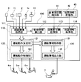
- FIG. 2 is a block diagram showing the internal configuration of the automatic operation control apparatus of this embodiment.
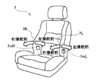
- FIG. 3A is an explanatory view exemplifying a state in which the acceleration / deceleration of the host vehicle is notified by inclining the backrest portion of the seat.
- FIG. 3B is an explanatory diagram showing the sign of the inclination angle of the seat back portion.
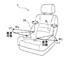
- FIG. 4A is an explanatory view exemplifying a state in which the right steering or the left steering of the host vehicle is notified in advance by tilting the lumbar support portion of the seat.
- FIG. 4B is an explanatory diagram showing the sign of the inclination angle of the lumbar support portion of the seat.
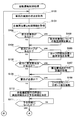
- FIG. 5 is a flowchart of the first half of the automatic driving control process executed by the automatic driving control device of this embodiment.
- FIG. 6 is a flowchart of the latter half of the automatic operation control process.
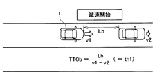
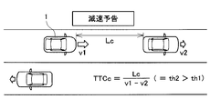
- FIG. 7A is an explanatory view exemplifying a state in which the automatic driving control device of the present embodiment determines the timing for notifying the content of the automatic driving operation and the start timing of the automatic driving operation based on the collision time.
- FIG. 7A is an explanatory view exemplifying a state in which the automatic driving control device of the present embodiment determines the timing for notifying the content of the automatic driving operation and the start timing of the automatic driving operation based on the
- FIG. 7B is an explanatory diagram illustrating a state in which the automatic driving control device according to the present embodiment determines the start of the automatic driving operation.
- FIG. 7C is an explanatory diagram illustrating a state in which the automatic driving control device according to the present embodiment determines the advance notice of the content of the automatic driving operation.
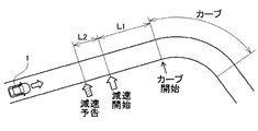
- FIG. 8A illustrates an example in which the automatic driving control device according to the present embodiment determines the time when the content of the automatic driving operation is notified and the start time of the automatic driving operation based on the distance to the object on the map.
- FIG. FIG. 8B shows another example in which the automatic driving control device according to the present embodiment determines the time when the content of the automatic driving operation is notified and the start time of the automatic driving operation based on the distance to the object on the map.
- FIG. 8A illustrates an example in which the automatic driving control device according to the present embodiment determines the time when the content of the automatic driving operation is notified and the start time of the automatic driving operation based on the distance to the object on the map
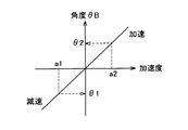
- FIG. 9 is an explanatory diagram illustrating a state in which the content of the automatic driving operation is notified by changing the angle ⁇ B of the seat back portion according to the acceleration of the host vehicle 1.
- FIG. 10 is an explanatory diagram illustrating a state in which the content of the automatic driving operation is notified in advance by changing the angle ⁇ L of the lumbar support portion of the seat according to the steering amount.
- FIG. 11A is an explanatory view illustrating another aspect in which the content of the automatic driving operation is notified by changing the angle ⁇ B of the seat back portion or the angle ⁇ L of the lumbar support portion.
- FIG. 10 is an explanatory diagram illustrating a state in which the content of the automatic driving operation is notified in advance by changing the angle ⁇ L of the lumbar support portion of the seat according to the steering amount.
- FIG. 11A is an explanatory view illustrating another aspect in which the content of the automatic driving operation is notified by changing the angle ⁇ B of the seat back portion or the angle ⁇ L of
- FIG. 11B is an explanatory view illustrating another mode in which the content of the automatic driving operation is notified by changing the angle ⁇ B of the seat back portion or the angle ⁇ L of the lumbar support portion.
- FIG. 11C is an explanatory view illustrating another mode in which the content of the automatic driving operation is notified by changing the angle ⁇ B of the seat back portion or the angle ⁇ L of the lumbar support portion.
- FIG. 12A is an explanatory view illustrating another aspect in which the content of the automatic driving operation is notified by vibrating the angle ⁇ B of the seat back portion or the angle ⁇ L of the lumbar support portion.
- FIG. 12B is an explanatory diagram illustrating another mode in which the content of the automatic driving operation is notified by vibrating the angle ⁇ B of the seat back portion or the angle ⁇ L of the lumbar support portion.
- FIG. 12C is an explanatory view illustrating another mode in which the content of the automatic driving operation is notified by vibrating the angle ⁇ B of the seat back portion or the angle ⁇ L of the lumbar support portion.
- FIG. 13 is an explanatory diagram illustrating a state in which the content of the automatic driving operation is notified in advance by changing the angle ⁇ B of the seat back portion according to the target vehicle speed of the host vehicle.
- FIG. 14 is an explanatory view exemplifying a state in which the content of steering by automatic driving is notified by changing the angle ⁇ L of the lumbar support portion of the seat.
- FIG. 15A is an explanatory view exemplifying non-steering in another mode in which the content of steering by automatic driving is notified in advance by tilting the lumbar support portion of the seat.
- FIG. 15B is an explanatory view exemplifying right steering in another mode in which the content of steering by automatic driving is notified in advance by tilting the lumbar support portion of the seat.
- FIG. 15C is an explanatory view exemplifying left steering in another mode in which the content of steering by automatic driving is notified in advance by tilting the lumbar support portion of the seat.
- FIG. 15A is an explanatory view exemplifying non-steering in another mode in which the content of steering by automatic driving is notified in advance by tilting the lumbar support portion of the seat.
- FIG. 16A is an explanatory view illustrating another aspect in which the content of the automatic driving operation is notified in advance by sliding the seat.
- FIG. 16B is an explanatory view illustrating another aspect in which the content of the automatic driving operation is notified in advance by sliding the seat.
- FIG. 17 is an explanatory diagram illustrating another aspect in which the content of the automatic driving operation is notified in advance by tilting the seat.
- FIG. 18A is an explanatory view illustrating another aspect in which the content of the automatic driving operation is notified in advance by moving the headrest of the seat.
- FIG. 18B is an explanatory view illustrating another aspect in which the content of the automatic driving operation is notified in advance by moving the headrest of the seat.
- FIG. 18A is an explanatory view illustrating another aspect in which the content of the automatic driving operation is notified in advance by moving the headrest of the seat.
- FIG. 18B is an explanatory view illustrating another aspect in which the content of the automatic driving operation is notified in advance by moving the head
- FIG. 19A is an explanatory view exemplifying a mode in which the content of the automatic driving operation is notified in advance by moving the moving floor surface mounted in front of the seat.
- FIG. 19B is an explanatory view exemplifying a mode in which the content of the automatic driving operation is notified in advance by moving the moving floor surface mounted in front of the seat.
- FIG. 20A is an explanatory diagram illustrating another aspect in which the content of the automatic driving operation is notified in advance by moving the moving floor surface mounted in front of the seat.
- FIG. 20B is an explanatory diagram illustrating another aspect in which the content of the automatic driving operation is notified in advance by moving the moving floor surface mounted in front of the seat.
- FIG. 21A is an explanatory view exemplifying a mode in which the content of an automatic driving operation is notified by moving an armrest mounted on the side of a seat.
- FIG. 21B is an explanatory view exemplifying a mode in which the content of the automatic driving operation is notified in advance by moving an armrest mounted on the side of the seat.
- FIG. 22A is an explanatory view illustrating another aspect in which the content of the automatic driving operation is notified in advance by moving the armrest mounted on the side of the seat.
- FIG. 22B is an explanatory view illustrating another aspect in which the content of the automatic driving operation is notified by moving the armrest mounted on the side of the seat.
- FIG. 23 is an explanatory diagram of an operation for requesting the driver to override by vibrating the backrest portion or the lumbar support portion during automatic driving.
- FIG. 1 shows a configuration of a host vehicle 1 equipped with an automatic driving control device 100 of the present embodiment.
- the host vehicle 1 according to the present embodiment includes a vehicle-mounted camera 2 that captures an image in the traveling direction, a radar 3 that detects other vehicles and obstacles existing in front, and a vehicle speed that detects the vehicle speed based on the rotation of the wheels 1w.
- a sensor 1t a sunshine sensor 1s that is mounted on the dashboard 1d of the host vehicle 1 and detects the amount of sunlight by the sun, a wireless communication device 10 that communicates with the outside by radio, and a route to a preset destination
- a navigation system shown below hereinafter referred to as a navigation system 40
- a steering handle actuator 6m for driving the steering handle 6, and the like are mounted. ing.
- the navigation system generally includes a function for detecting the position of the host vehicle 1, a function for storing map information, a function for setting a destination, a function for searching for a route to the destination, and a search. It is a system with the function of presenting the route and guiding the route.
- the automatic driving control device 100 detects the position of the host vehicle 1 using the navigation system 40 and grasps the situation ahead of the host vehicle 1 using the map information stored in the navigation system 40.
- a function for searching and presenting a route to a set destination may not necessarily be installed. Therefore, the navigation system 40 of the present embodiment is a system that omits a function for setting a destination, a function for searching a route to the destination, and a function for presenting the searched route from a general navigation system. You can also
- the automatic driving control device 100 detects the situation around the host vehicle 1 based on the captured image obtained by the in-vehicle camera 2 and the output of the radar 3, and the accelerator pedal actuator 4 m according to the route indicated by the navigation system 40. Alternatively, automatic driving is executed by driving the brake pedal actuator 5m and the steering handle actuator 6m. In this embodiment, for the purpose of avoiding complicated description, the automatic driving control apparatus 100 detects the surrounding situation exclusively using the image taken by the in-vehicle camera 2 or uses the output of the radar 3. Although described as detecting the surrounding situation, the surrounding situation may be detected using a sonar (not shown).
- a plurality of actuators for moving the backrest and the lumbar support are built in the seat 7 on the driver's seat side where the steering handle 6 is provided. It is possible to control the movement of the.
- the seat 7 is described as a seat on the driver's seat side, but it may be a seat other than the driver's seat (that is, a passenger seat or a rear seat).
- FIG. 2 shows a rough internal configuration of the automatic operation control apparatus 100 of the present embodiment.
- the automatic driving control device 100 includes a driving environment acquisition module 110 that acquires various information related to the driving environment of the host vehicle 1, an automatic driving execution module 120 that executes automatic driving, and the contents of the automatic driving operation.
- the driving operation notice module 130 is provided with three main modules.
- the automatic driving execution module 120 corresponds to the “automatic driving control unit”, and the driving operation notice module 130 corresponds to the “driving information output device”.
- the driving environment acquisition module 110 is provided with an ambient environment acquisition unit 111, a collision time calculation unit 112, a host vehicle position acquisition unit 113, and a map information acquisition unit 114. Furthermore, the automatic operation execution module 120 is provided with a driving operation determination unit 121 and a driving operation control unit 122, and the driving operation notice module 130 is provided with a driving information acquisition unit 131 and a driving information output unit 132. It has been.
- modules or “parts” refer to the functions that the automatic driving control device 100 has in order to notify the driver of the details of the driving operation during the automatic driving. It is an abstract concept that is classified for convenience. Therefore, it does not indicate that the automatic operation control apparatus 100 is physically divided into these “modules” or “parts”.
- modules or “units” can be realized as a computer program executed by the CPU, or can be realized as an electronic circuit including an LSI or a memory, and further, by combining them. It can also be realized.
- the ambient environment acquisition unit 111 of the traveling environment acquisition module 110 is connected to the in-vehicle camera 2, the radar 3, the vehicle speed sensor 1t, the sunshine sensor 1s, and the wireless communication device 10. Among these, by acquiring a captured image from the in-vehicle camera 2 and analyzing the acquired captured image, other vehicles existing in front of the host vehicle 1, obstacles, pedestrians, and the like are detected. In addition, the radar 3 detects the presence of other vehicles, obstacles, pedestrians, and the like that are present ahead, and the distance from the host vehicle 1. The speed of the host vehicle 1 is acquired from the vehicle speed sensor 1t, and the intensity of sunlight (that is, the amount of sunlight) is acquired from the sunshine sensor 1s. Furthermore, the ambient environment acquisition unit 111 communicates with other vehicles, traffic lights, roadside devices, etc. that exist in the surroundings using the wireless communication device 10, so that information such as the vehicle speed of other vehicles, information regarding display of traffic lights, Information on traffic conditions can also be acquired.
- the collision time calculation unit 112 calculates the collision time for other vehicles, pedestrians, obstacles, and the like existing ahead.
- the collision time is an expected time until the vehicle collides with another vehicle, a pedestrian, an obstacle, or the like (hereinafter referred to as a “front object”) existing ahead when the current vehicle speed is continued.
- the collision time can be obtained by dividing the distance from the host vehicle 1 to the front object by the relative speed between the host vehicle 1 and the front object.
- the ambient environment acquisition unit 111 can detect the presence / absence of the front object and the distance to the front object based on the captured image from the in-vehicle camera 2 and the output of the radar 3. Therefore, when the front environment object is detected by the surrounding environment acquisition unit 111, the collision time calculation unit 112 acquires the distance to the front object. Further, each time a certain time elapses, the relative speed between the front object, the host vehicle 1 and the front object is calculated by acquiring the distance to the front object. Then, the collision time for the front object is calculated by dividing the distance to the front object by the relative speed thus obtained.
- the difference between the vehicle speed of the other vehicle acquired by performing inter-vehicle communication using the wireless communication device 10 and the vehicle speed of the host vehicle 1 obtained from the vehicle speed sensor 1t is calculated. It is also possible to calculate the relative speed by obtaining.
- the own vehicle position acquisition unit 113 acquires the current position of the own vehicle 1 from the own vehicle position detection unit 41 built in the navigation system 40.
- the own vehicle position detection unit 41 can detect the current position of the own vehicle 1 by receiving a signal from a positioning satellite.
- the map information acquisition unit 114 acquires map information of the surrounding area including the current position of the host vehicle 1 from the map information storage unit 42 built in the navigation system 40.
- the collision time calculation unit 112 may acquire these pieces of information to calculate the collision time for a curve or intersection existing ahead.
- the driving operation determination unit 121 of the automatic driving execution module 120 includes the above-described various types of information from the surrounding environment acquisition unit 111, the collision time calculation unit 112, the host vehicle position acquisition unit 113, and the map information acquisition unit 114 of the traveling environment acquisition module 110. Information is acquired and the driving
- the driving operation of the host vehicle 1 is a concept including the operation amount of these driving operations in addition to the types of driving operations such as acceleration and deceleration, left steering and right steering of the host vehicle 1. Further, an operation amount 0 for acceleration or deceleration represents a driving operation for maintaining the current speed, and an operation amount 0 for left steering or right steering represents a driving operation for going straight.
- the subsequent behavior of the host vehicle 1 (for example, vehicle speed, acceleration, lateral acceleration, and lateral speed component) can be predicted. Therefore, when the driving operation of the host vehicle 1 is determined, it may be determined as the driving operation including these behaviors.
- the driving operation control unit 122 controls the accelerator pedal actuator 4m, the brake pedal actuator 5m, and the steering handle actuator 6m according to the driving operation determined by the driving operation determination unit 121.
- the driving operation determination unit 121 outputs driving information regarding the content of the driving operation to the driving information acquisition unit 131 of the driving operation notice module 130. Then, the driving information acquisition unit 131 outputs the received driving information to the driving information output unit 132. Then, the driving information output unit 132 drives an actuator (described later) built in the seat 7 to move the backrest and lumbar support of the seat 7, thereby occupant (non-sitting) sitting on the seat 7 on the driver's seat side. Driving information is presented to the driver during automatic driving.
- FIG. 3A and FIG. 3B illustrate how acceleration / deceleration of the host vehicle 1 is presented by inclining the backrest portion 7b of the seat 7 of this embodiment.
- an electric actuator 7mT is built in a portion where the backrest portion 7b of the seat 7 is attached to the seat surface portion 7a.
- the backrest part 7b can be inclined with respect to the seat surface part 7a by driving the electric actuator 7mT.
- the automatic driving control device 100 of the present embodiment drives the electric actuator 7mT so that the backrest portion 7b is tilted backward.
- the electric actuator 7mT is driven so that the backrest 7b is tilted forward.
- the angle ⁇ B of the backrest 7b is “positive” when the backrest 7b is tilted backward, and is “negative” when it is tilted forward.
- the electric actuator 7mT of the present embodiment corresponds to a “drive unit”.
- FIG. 4A and 4B illustrate a state in which the right steering or the left steering of the host vehicle 1 is presented by tilting the lumbar support portions 7R and 7L of the seat 7 of the present embodiment.
- an electric actuator 7mR is built in the right lumbar support portion 7R of the seat 7, and an electric actuator 7mL is built in the left lumbar support portion 7L.
- the left and right lumbar support portions 7R and 7L can be tilted left and right with respect to the backrest portion 7b.
- the automatic driving control device 100 tilts the left and right lumbar support portions 7R and 7L to the right when viewed from the occupant sitting on the seat 7 when the host vehicle 1 is steered to the right.
- the electric actuators 7mR and 7mL are driven as described above. Further, when the host vehicle 1 is steered to the left, the electric actuators 7mR and 7mL are driven so that the left and right lumbar support portions 7R and 7L are tilted to the left as viewed from the passenger sitting on the seat 7.
- the angle ⁇ L of the lumbar support portions 7R and 7L is “positive” when the lumbar support portions 7R and 7L are tilted to the right, and is “negative” when the lumbar support portions 7R and 7L are tilted to the left.
- the electric actuator 7mR and the electric actuator 7mL of the present embodiment also correspond to the “drive unit”.
- the automatic operation control device 100 of the present embodiment drives the electric actuator 7mT built in the seat 7 to tilt the backrest portion 7b, or drives the electric actuators 7mR, 7mL to drive the left and right lumbar support portions 7R, By tilting 7L, driving information during automatic driving can be presented to the occupant sitting on the seat 7. As a result, it is possible to automatically drive the passenger sitting on the seat 7 without feeling uncomfortable.
- a process executed by the automatic driving control apparatus 100 of the present embodiment will be described.
- the driving information is described as being presented to the occupant of the seat 7 on the driver's seat side, but the driving information may be presented to the occupant sitting on the seat 7 other than the driver's seat. .
- the situation around the host vehicle 1 is acquired (S100).
- the traveling environment acquisition module 110 is connected to the in-vehicle camera 2, the radar 3, the vehicle speed sensor 1 t, the sunshine sensor 1 s, and the wireless communication device 10. Based on these outputs, the surrounding situation is acquired.
- sonar etc. may be mounted on the host vehicle 1 and the surrounding situation may be acquired using these.
- the current position of the host vehicle 1 (hereinafter also referred to as the host vehicle position) and surrounding map information including the host vehicle position are acquired from the navigation system 40 (S101).
- the travel environment acquisition module 110 is also connected to the navigation system 40, acquires the vehicle position from the vehicle position detection unit 41 of the navigation system 40, and the map information storage unit 42. Map information can be obtained from.
- Whether there is a front object can be determined by analyzing a captured image obtained from the in-vehicle camera 2 or analyzing the output of the radar 3.
- the collision time for the front object is calculated (S103).
- the collision time can be calculated by dividing the distance from the host vehicle 1 to the front object by the relative speed between the host vehicle 1 and the front object.
- the distance from the own vehicle 1 to the front object can be obtained based on the output of the radar 3, and the relative speed between the own vehicle 1 and the front object is based on the time change of the distance to the front object. Can be sought.
- a curve exists ahead of the host vehicle 1 without calculating the collision time S104. Whether or not a curve exists can be determined by acquiring the shape of the road included in the map information. Alternatively, the road shape may be acquired by analyzing an image captured by the in-vehicle camera 2 and detecting a lane (or a white line).
- the curve start position and the curvature radius of the curve are acquired (S105).
- the start position of the curve and the radius of curvature can also be obtained from the map information. Or based on the road shape acquired from the image
- the points requiring attention are points that require attention when the driver manually operates, such as intersections, tunnel entrances, tunnel exits, and climbing slope end points. That is, since it is known that accidents are likely to occur at intersections, attention must be paid to driving. Also, since the brightness changes suddenly at the tunnel entrance and tunnel exit and visibility is easily lost, attention is required for driving. Furthermore, at the end point of the uphill, the sight is worsened because the uphill is switched to the downhill, so attention must be paid to driving.
- the automatic driving control device 100 can easily determine whether or not there is a point of interest in front of the host vehicle 1. .
- the presence / absence of a point requiring attention may be determined based on information acquired from the outside using the wireless communication device 10.
- the driver tends to decelerate halfway or travel at a lower vehicle speed. Therefore, by analyzing the image taken by the in-vehicle camera 2, the degree of visibility in the forward direction of the host vehicle 1 is detected, and when the degree of visibility falls below a predetermined value, it approaches a point requiring attention. You may judge it.
- the wireless communication device 10 by communicating with the outside via the wireless communication device 10, whether or not there is a point with a low visibility in front of the host vehicle 1, and if there is a point with a low visibility, the distance to that point is acquired. May be. If such a point exists within a certain distance from the host vehicle 1, it may be determined that a point requiring attention exists.
- a warning is issued by vibrating the left and right lumbar support portions 7R and 7L (S109).
- the left and right lumbar support portions 7R and 7L are vibrated by driving the electric actuators 7mL and 7mR in opposite directions.
- a vibrator may be built in the lumbar support portions 7R and 7L, and the lumbar support portions 7R and 7L may be vibrated by driving the vibrator.
- a vibrator may be built in the seat surface portion 7a of the seat 7, and the seat surface portion 7a may be vibrated by driving the vibrator.
- the content of the automatic driving operation and the execution timing of the automatic driving operation are determined (S110). For example, when the destination is set for the navigation system 40, the accelerator pedal 4 and the brake pedal 5 are based on the route information indicated by the navigation system 40 and the situation around the host vehicle 1. Then, whether or not to operate the steering handle 6 and the operation amount are determined.
- the host vehicle 1 including the position of the preceding vehicle based on the captured image obtained by the in-vehicle camera 2 or based on the output of the radar 3.
- the accelerator pedal 4 By detecting the surrounding situation, whether or not to operate the accelerator pedal 4, the brake pedal 5 and the steering handle 6 and the operation amount are determined.
- the start position of the curve and the curvature radius of the curve are acquired in S105 of FIG. Since an appropriate vehicle speed (hereinafter referred to as an approach speed) when entering the curve is determined according to the curvature radius of the curve, the approach speed according to the curvature radius is determined and compared with the vehicle speed of the host vehicle 1.
- an appropriate vehicle speed hereinafter referred to as an approach speed
- the vehicle decelerates at a speed corresponding to the vehicle speed of the host vehicle 1 at a point before the distance L3 from the position of the intersection. Decide to stop. In addition, it is determined that the vehicle will be notified of deceleration at a point that is further in front of the distance L4 than the point at which deceleration is started.
- FIG. 3A and 3B illustrate a state in which the acceleration or deceleration is notified by tilting the backrest portion 7b of the seat 7.
- left steering it is determined whether the steering handle 6 is steered leftward (hereinafter, left steering) (S118).
- left steering is performed by driving the electric actuator 7mR and the electric actuator 7mL according to the steering amount and tilting the lumbar support portion 7R and the lumbar support portion 7L to the left.
- “inclined to the left” means to incline to the left as viewed from the occupant sitting on the seat 7.
- 4A and 4B illustrate a state in which the right steering or the left steering is notified by tilting the lumbar support portion 7R and the lumbar support portion 7L to the right or left.
- the electric actuator 7mR and the electric actuator 7mL are not driven.
- the lumbar support portion 7R and the lumbar support portion 7L are maintained in a state in which they are not inclined in either the left or right direction.
- the movement is recognized by the occupant sitting on the seat 7, and the contents are clarified before the automatic driving operation is performed. Can tell. For this reason, the occupant sitting on the seat 7 can recognize in advance the content of the automatic driving operation to be performed in the future, and can avoid feeling uncomfortable with respect to the automatic driving.
- the contents of the automatic driving operation are transmitted to the occupant by the movement of the backrest portion 7b of the seat 7 and the lumbar support portions 7R and 7L, the occupant feels annoying or bothered, unlike when appealing to the eyes or hearing. I don't feel it. For this reason, even when telling the contents of the driving operation one by one during the automatic driving, it is possible to transmit it without giving a burden to the occupant.
- the angle ⁇ B for inclining the backrest 7b of the seat 7 is set to the following angle according to the acceleration / deceleration of the host vehicle 1.
- FIG. 9 illustrates the angle ⁇ B of the backrest 7b set according to the degree of acceleration or deceleration.
- the angle ⁇ B of the backrest 7b is positive when the backrest 7b is tilted backward from a predetermined reference position and negative when the backrest 7b is raised from the reference position. Become.
- the angle ⁇ B of the backrest portion 7b is set to a positive value, and when the host vehicle 1 is decelerated, the angle ⁇ B of the backrest portion 7b is set to a negative value. .
- the absolute value of the angle ⁇ B is set to a larger value as the absolute value of the acceleration increases. For this reason, the driver can recognize whether the host vehicle 1 is going to accelerate or decelerate from the movement of the backrest portion 7b tilting back and forth. Furthermore, the degree of acceleration or deceleration can be recognized from the magnitude of the angle ⁇ B of the backrest 7b.
- the angle ⁇ B of the backrest 7b is returned to the reference position in preparation for the next notification of acceleration or deceleration. At this time, it is desirable that the speed at which the backrest 7b is returned is as small as not noticed by the driver.
- angle ⁇ B of the backrest 7b corresponds to the “target position”.
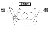
- the angle ⁇ L for inclining the left and right lumbar support portions 7R, 7L of the seat 7 is set to the following angle according to the steering amount of the right steering or the left steering of the host vehicle 1.
- FIG. 10 illustrates the angle ⁇ L of the lumbar support portions 7R and 7L set according to the steering amount of the host vehicle 1.
- the angle ⁇ L for tilting the left and right lumbar support portions 7R and 7L is tilted to the right with respect to a predetermined reference position when viewed from the occupant sitting on the seat 7.
- the direction is positive and the direction tilted to the left is negative.
- the angle ⁇ L of the lumbar support portions 7R, 7L is set to a positive value
- the angle ⁇ L of 7L is set to a negative value.
- the driver can recognize whether the host vehicle 1 is about to steer right or left from the direction in which the lumbar support portions 7R and 7L are inclined.
- the steering amount of the right steering or the left steering can also be recognized from the magnitude of the absolute value of the angle ⁇ L of the lumbar support portions 7R and 7L.
- the angle ⁇ L of the lumbar support portions 7R and 7L is returned to the reference position in preparation for the next notification of the right steering or the left steering. At this time, it is desirable that the speed at which the lumbar support portions 7R and 7L are returned is as small as not noticed by the driver.
- angle ⁇ L of the lumbar support portions 7R and 7L also corresponds to the “target position”.
- the automatic driving control device 100 executes the automatic driving operation by driving the accelerator pedal actuator 4m, the brake pedal actuator 5m, and the steering handle actuator 6m according to the content determined in S110 (S121).
- the automatic driving control device 100 determines whether or not the automatic driving is to be ended (S122), and if it is not to be ended (S122: no), the process returns to the top of the process to acquire the situation around the host vehicle 1. After that (S100 in FIG. 5), the above-described series of processing (S101 to S122) is executed. And while repeating such operation, when it is judged that automatic driving
- the automatic driving control device 100 determines the content of the automatic driving operation
- the backrest portion 7b of the seat 7 and the lumbar support portions 7R and 7L are inclined according to the content. .
- the passenger of the host vehicle 1 can recognize in advance the content of the automatic driving operation from the movement of the backrest portion 7b and the lumbar support portions 7R and 7L.
- the content of the automatic driving operation is not a driving method which is naturally felt by the occupant, it can be avoided that the occupant feels uncomfortable.
- the driving method during automatic driving is different from the driving method that the occupant feels natural, the vehicle can be automatically driven without causing the occupant to feel uncomfortable.
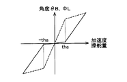
- the inclination ⁇ B of the backrest portion 7b with respect to the acceleration is different depending on whether the absolute value of the acceleration is equal to or less than the predetermined value tha and greater than the predetermined value tha.
- the inclination may be smaller than when the value is equal to or greater than the predetermined value tha.
- the absolute value of the steering amount is less than the predetermined value tha and the absolute value of the steering amount is greater than the predetermined value tha.
- the inclination of the angle ⁇ L of the lumbar support portions 7R and 7L may be made different so that the inclination is smaller than the predetermined value tha when the inclination is less than the predetermined value tha.
- the driver does not know the movement of the backrest part 7b and the lumbar support parts 7R, 7L or can be made not to worry about it. For this reason, the backrest part 7b and the lumbar support parts 7R and 7L move each time a small acceleration / deceleration or steering is performed, and there is no possibility that the driver feels troublesome.
- the angle ⁇ B or the angle ⁇ L changes even when the absolute value of the acceleration or the steering amount is smaller than the predetermined value tha. However, in the range smaller than the predetermined value tha, the angle ⁇ B or The angle ⁇ L may not be changed.
- the inclination of the angle ⁇ B of the backrest portion 7b with respect to the acceleration is larger than when the absolute value is equal to or larger than the predetermined value tha. Also good.
- the angle ⁇ L of the lumbar support portions 7R, 7L is steered when the absolute value of the steering amount is equal to or less than the predetermined value tha as illustrated by the broken line in the figure. You may make it the angle (phi) L of the lumbar support parts 7R and 7L with respect to quantity increase.
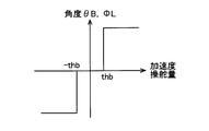
- the backrest portion 7b and the lumbar support portions 7R and 7L are tilted to a certain angle.
- the backrest portion 7b and the lumbar support portions 7R and 7L may not be inclined.
- the backrest portion 7b and the lumbar support portions 7R, 7L do not move, so that the driver does not feel bothersome. Further, in the case of acceleration / deceleration or steering where there is a great need to notify the driver, the backrest portion 7b and the lumbar support portions 7R and 7L move greatly at a fixed angle, so the vehicle 1 is about to accelerate or decelerate. The driver can clearly recognize that he is trying to steer.
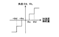
- the backrest portion 7b and the lumbar support portions 7R and 7L may be inclined in a plurality of stages. For example, the case where the host vehicle 1 is going to be accelerated will be described. When the acceleration is larger than thc, the backrest 7b is tilted backward at a certain angle, but when the acceleration is larger than thd, it is larger. The backrest 7b may be tilted backward at an angle.
- the lumbar support portions 7R and 7L are tilted to a certain angle when the steering amount is larger than thc, but when the steering amount becomes larger than thd, a larger angle is obtained.
- the lumbar support portions 7R and 7L may be inclined.
- the driver can roughly recognize the degree of acceleration / deceleration and steering from the rough movement of the backrest portion 7b and the lumbar support portions 7R, 7L. Can be recognized properly.
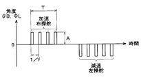
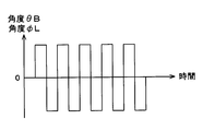
- the degree of acceleration / deceleration and steering may be transmitted to the driver by vibrating the inclination of the backrest portion 7b and the lumbar support portions 7R and 7L.
- the backrest portion 7b is tilted in the forward direction (that is, rearward), and the original angle
- the backrest portion 7b is caused to vibrate in the negative direction (i.e., forward) and is then vibrated by repeating the operation of returning the original angle. In this way, the driver can recognize whether the host vehicle 1 is about to accelerate or decelerate depending on the direction in which the backrest 7b vibrates.
- the lumbar support unit 7R, 7L is tilted in the positive direction (that is, the right direction) and then returned to the original state, thereby repeating the lumbar support unit. 7R and 7L are vibrated. Further, in the case of left steering, the lumbar support portions 7R and 7L are vibrated by repeating the operation of inclining the lumbar support portions 7R and 7L in the negative direction (that is, the left direction) and returning them to their original positions. In this way, the driver can recognize whether the host vehicle 1 is about to steer right or left depending on the direction in which the lumbar support portions 7R and 7L vibrate.
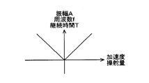
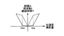
- the amplitude A for vibrating the backrest portion 7b, the lumbar support portions 7R and 7L, the frequency f for vibrating, and the duration T of vibration may be changed according to the degree of acceleration / deceleration or the degree of steering. For example, as illustrated in FIG. 12B, even when the backrest 7b is vibrated in such a manner that at least one of the amplitude A, the frequency f, and the duration T increases as the absolute value of acceleration or deceleration increases. good.
- the lumbar support portions 7R and 7L may be vibrated in such a manner that at least one of the amplitude A, the frequency f, and the duration T increases as the steering amount increases. In this way, the driver can recognize the degree of acceleration / deceleration and steering from the aspect in which the backrest portion 7b and the lumbar support portions 7R and 7L vibrate.
- the change amount of the amplitude A when the absolute value of the acceleration changes by a unit amount, the change amount of the frequency f, and the change amount of the duration T are set in a range where the absolute value of the acceleration is smaller than the threshold value the It may be different for larger ranges.
- the change amount of the amplitude A when the steering amount changes by a unit amount, the change amount of the frequency f, and the change amount of the duration T are set to a range where the steering amount is smaller than the threshold value the and the threshold value the. It may be different for larger ranges.
- the amplitude A with respect to the change in the unit amount of acceleration, the frequency f, The amount of change in the duration time T may be reduced.
- the amount of change in the amplitude A, the frequency f, and the duration T with respect to the change in the unit amount of the steering amount is smaller in the range where the steering amount is smaller than the threshold thee. You may make it become.
- the amplitude A, the frequency f, and the duration time with respect to the change in the unit amount of acceleration are larger than when the absolute value is equal to or larger than the predetermined value the.
- the amount of change in T may be increased.
- the angle ⁇ L of the lumbar support portions 7R and 7L is steered when the absolute value of the steering amount is equal to or less than the predetermined value the as shown by the broken line in the figure. You may make it the variation
- the backrest 7 b is tilted so that the angle ⁇ B of the backrest 7 b becomes an angle according to the control target value of the vehicle speed of the host vehicle 1 (that is, the target vehicle speed). Also good. Even in this way, the driver can recognize the target vehicle speed from the inclination of the backrest 7b.
- the angle ⁇ B at which the backrest portion 7b is tilted with respect to the target vehicle speed can be set in various manners as in the case of tilting according to the acceleration.
- the change in the angle ⁇ B with respect to the change amount of the target vehicle speed is larger than when the absolute value is larger than the predetermined threshold. The amount may be reduced.
- the angle ⁇ B may be varied stepwise with respect to the target vehicle speed.
- the driver may be notified that the target vehicle speed is to be changed by vibrating the backrest 7b.
- the backrest portion 7b is vibrated in the positive direction (that is, backward), and when the target vehicle speed is decreased, the backrest portion 7b is vibrated in the negative direction (that is, forward). May be.
- the driver can be made aware of whether the target vehicle speed is about to be increased or decreased depending on the direction in which the backrest 7b vibrates.
- the amplitude A for vibrating the backrest 7b, the frequency f for vibrating, and the duration T of vibration may be changed according to the target vehicle speed.
- the backrest portion 7b is vibrated in such a manner that as the absolute value of the target vehicle speed increases, at least one of the amplitude A, the frequency f, and the duration T increases. You may let them.
- the amount of change in T may be varied.
- the lumbar support portions 7R and 7L are tilted so that the angle ⁇ L for tilting the lumbar support portions 7R and 7L becomes an angle determined according to the steering speed of the host vehicle 1. It is also good. Even in this way, the driver can recognize the steering direction and the steering speed from the inclination of the lumbar support portions 7R and 7L.
- the lateral acceleration hereinafter referred to as lateral acceleration
- the lateral speed hereinafter referred to as lateral speed
- the lumbar support portions 7R and 7L may be tilted so as to have an angle. Even in this way, the driver can recognize in which direction the own vehicle 1 is about to steer in what direction from the inclination of the lumbar support portions 7R and 7L.
- the automatic driving control device 100 determines the content of the automatic driving operation, and does not determine the lateral acceleration or the lateral speed of the host vehicle 1. However, since the automatic acceleration control device 100 determines the steering amount and the steering speed as the contents of the automatic driving operation, the lateral acceleration and the lateral velocity are determined indirectly by the automatic driving control device 100. You can also think that Therefore, the steering amount and steering speed directly determined by the automatic driving control apparatus 100 and the lateral acceleration and lateral speed determined indirectly may be collectively referred to as “steering information”.
- the angle ⁇ L for tilting the lumbar support portions 7R and 7L is various in the same manner as when tilting according to the steering amount.
- the angle ⁇ L may be varied stepwise with respect to the steering speed, the lateral acceleration, and the lateral speed.
- the lumbar support portions 7R and 7L are vibrated to notify the driver that the steering speed, the lateral acceleration, and the lateral speed are to be changed. Also good.
- the lumbar support portions 7R and 7L are vibrated in the forward direction (that is, rightward when viewed from the occupant sitting on the seat 7), and the steering speed and the lateral speed are increased.
- the lumbar support portions 7R and 7L may be vibrated in the negative direction (that is, leftward as viewed from the occupant sitting on the seat 7).
- the amplitude A for vibrating the lumbar support portions 7R and 7L, the frequency f for vibrating, and the vibration duration T may be changed according to the steering speed, the lateral acceleration, and the lateral speed.
- the amplitude A, the frequency f, and the duration T increases as the steering speed, the lateral acceleration, and the absolute value of the lateral speed increase.
- the lumbar support portions 7R and 7L may be vibrated.
- the amount of change and the amount of change in duration T may be different.
- 15A to 15C exemplify a state in which the left and right lumbar support portions 7R and 7L share the notice of the steering content.
- 15A to 15C show the movements of the left and right lumbar support portions 7R and 7L with the seat 7 looking down from above.
- the broken line shown in the drawing represents an occupant sitting on the seat 7.
- the right lumbar support portion 7R and the left lumbar support portion 7L are at the reference positions.
- the lumbar support portion 7R on the right side remains at the reference position and the lumbar support portion 7L on the left side is in the forward direction (the passenger sitting on the seat 7). Tilt to the right).
- the left lumbar support portion 7L is tilted and the left side of the occupant is pushed rightward. Therefore, the occupant can clearly recognize that the lumbar support portion 7L is tilted to the right, and as a result, can easily recognize that the host vehicle 1 is about to steer right.
- the left lumbar support portion 7L remains at the reference position and the right lumbar support portion 7R is in the negative direction (sitting on the seat 7). Tilt to the left (when viewed from the passenger).
- the right lumbar support portion 7R is tilted and the right side of the occupant is pushed leftward. Therefore, the occupant can clearly recognize that the lumbar support portion 7R is tilted leftward, and as a result, can easily recognize that the host vehicle 1 is about to steer to the left.
- 16A to 16B illustrate a first modified example in which the seat 7 is moved in translation according to the content of the automatic driving operation.
- the seat 7 is provided so as to be slidable in the front-rear direction, and the seat 7 can be translated in the front-rear direction by driving an electric actuator 7 mF built in the seat 7. Yes.
- the seat 7 when the content of the automatic driving operation is acceleration, the seat 7 is moved in the forward direction from the reference position (that is, the forward direction as viewed from the occupant sitting on the seat 7).
- the seat 7 When the content of the automatic driving operation is deceleration, the seat 7 is moved in the negative direction from the reference position (that is, backward as viewed from the occupant sitting on the seat 7). In this way, the occupant can recognize whether the host vehicle 1 is about to accelerate or decelerate.
- target position La for moving the seat 7 at this time corresponds to the “target position”.
- the seat 7 may be slidable in the left-right direction, and the seat 7 may be translated in the left-right direction by driving an electric actuator 7mS built in the seat 7. .
- the seat 7 is moved in the forward direction from the reference position (that is, rightward when viewed from the occupant sitting on the seat 7), and the automatic driving is performed.
- the content of the operation is left steering, the seat 7 is moved in the negative direction from the reference position (that is, leftward as viewed from the occupant sitting on the seat 7). In this way, it is possible to make the occupant recognize whether the vehicle 1 is about to steer right or left.
- the target position Lb for moving the seat 7 or the target rotational position for rotating the seat 7 also corresponds to the “target position”.
- the manner in which the seat 7 is moved in the front-rear direction or the left-right direction according to the magnitude of the acceleration or the steering amount is set in various manners as in the above-described embodiment. Can do.
- the magnitude of acceleration and steering amount may be proportional to the amount of movement of the seat 7.
- the amount of change in acceleration or steering amount is larger than when the absolute value or steering amount is larger than the predetermined threshold.
- the change amount of the movement amount may be reduced.
- the movement amount may be changed stepwise with respect to the acceleration and the steering amount.
- the driver may be notified of acceleration / deceleration or steering by vibrating the entire seat 7 back and forth or left and right.
- the amplitude A for vibrating the entire seat 7 forward and backward or left and right, the frequency f for vibrating, and the duration T of vibration may be changed according to the acceleration and the steering amount.
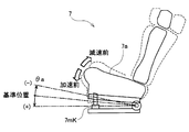
- FIG. 17 illustrates a second modification in which the entire seat 7 is tilted according to the content of the automatic driving operation.
- an electric actuator 7mK is built in the front lower portion of the seat surface portion 7a of the seat 7. Then, when the electric actuator 7mK is driven to lift the front side of the seat surface portion 7a, the entire seat 7 is inclined with the rear side of the seat surface portion 7a as the rotation axis.
- the seat 7 when the content of the automatic driving operation is acceleration, the seat 7 is rotated in the forward direction from the reference position (that is, the direction in which the front of the seat surface portion 7a is lowered), and the automatic driving operation is performed. Is the deceleration, the seat 7 is rotated from the reference position in the negative direction (that is, the direction in which the front of the seat surface portion 7a is raised). In this way, it is possible to make the occupant recognize whether the host vehicle 1 is about to accelerate or decelerate.
- target rotation angle ⁇ a for rotating the seat 7 at this time also corresponds to the “target position”.
- the manner in which the seat 7 is rotated in accordance with the magnitude of acceleration can be in various manners as in the above-described embodiment.
- the magnitude of acceleration may be proportional to the angle at which the seat 7 is rotated.
- the amount of change in angle relative to the amount of change in acceleration is smaller than when the absolute value is larger than the predetermined threshold. May be.
- the angle at which the seat 7 is rotated may be changed stepwise with respect to the acceleration.
- the driver may be informed of acceleration / deceleration by vibrating the entire seat 7.
- the amplitude A for vibrating the entire seat 7, the frequency f for vibrating, and the duration T of vibration may be changed according to the acceleration.
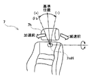
- 18A to 18B illustrate a third modified example in which the headrest 7h is moved according to the content of the automatic driving operation.
- the headrest 7h is inclined in the front-rear direction with respect to the seat 7.
- the headrest 7h can be inclined in the front-rear direction. It has become.
- the headrest 7h when the content of the automatic driving operation is acceleration, the headrest 7h is rotated in the forward direction from the reference position (that is, the direction in which the headrest 7h moves forward), and the automatic driving operation is performed. If the content of is the deceleration, the headrest 7h is rotated in the negative direction from the reference position (that is, the direction in which the headrest 7h moves backward). In this way, the occupant can recognize whether the host vehicle 1 is about to accelerate or decelerate.
- target rotation angle ⁇ b for rotating the headrest 7h at this time also corresponds to the “target position”.
- the headrest 7h may be rotated in the left-right direction by driving the electric actuator 7mG built in the headrest 7h in the left-right direction.
- the headrest 7h is rotated in the forward direction from the reference position (that is, rightward when viewed from the occupant sitting on the seat 7), and the automatic driving operation is performed.
- the headrest 7h is rotated in the negative direction from the reference position (that is, leftward as viewed from the occupant sitting on the seat 7). In this way, it is possible to make the occupant recognize whether the vehicle 1 is about to steer right or left.
- both the target for rotating the seat 7 and the rotation angle ⁇ c correspond to the “target position”. Further, the electric actuator 7mH and the electric actuator 7mG of this modification also correspond to the “driving unit”.
- the manner in which the headrest 7h is rotated in the front-rear direction or the left-right direction in accordance with the magnitude of the acceleration or the steering amount is various as in the above-described embodiment. be able to.
- the magnitude of acceleration and steering amount may be proportional to the angle at which the headrest 7h is rotated.
- the amount of change in acceleration or steering amount when the absolute value of acceleration or the steering amount is smaller than a predetermined threshold, the amount of change in acceleration or steering amount is larger than when the absolute value or steering amount is larger than the predetermined threshold.
- the amount of change in angle may be reduced.
- the angle at which the headrest 7h is rotated may be varied stepwise with respect to the acceleration and the steering amount.
- the driver may be notified of acceleration / deceleration or steering by vibrating the headrest 7h back and forth or left and right.
- the amplitude A for vibrating the headrest 7h back and forth or left and right, the frequency f for vibrating, and the duration T of vibration may be changed according to the acceleration and the steering amount.
- a part of the floor surface in front of the seat 7 may be movably provided, and the contents of the automatic driving operation may be notified in advance by moving the movable floor surface (hereinafter referred to as a movable floor surface). good.
- 19A to 19B illustrate a fourth modified example in which the moving floor surface 8a is moved in accordance with the contents of the automatic driving operation.
- the movable floor surface 8a of the fourth modified example is attached to the base portion 8b attached to the floor surface of the host vehicle 1 so as to be slidable in the front-rear direction and the left-right direction.
- the moving floor surface 8a can be slid in the front-rear direction using the electric actuator 8c, and can be slid in the left-right direction using the electric actuator 8d.
- the moving floor 8a when the content of the automatic driving operation is acceleration, the moving floor 8a is moved forward from the reference position, and when the content of the automatic driving operation is deceleration. The moving floor 8a is moved backward from the reference position. In this way, the occupant can recognize whether the host vehicle 1 is about to accelerate or decelerate.
- target position Ld for moving the moving floor 8a at this time also corresponds to the “target position”.
- the moving floor 8a is moved to the right of the reference position when viewed from the passenger sitting on the seat 7, and the content of the automatic driving operation is left steering. If it is, the moving floor 8a is moved to the left of the reference position when viewed from the occupant sitting on the seat 7. In this way, it is possible to make the occupant recognize whether the vehicle 1 is about to steer right or left.
- the target position Le for moving the moving floor 8a also corresponds to the “target position”.
- the moving floor surface 8a can be moved in the front-rear direction or the left-right direction in accordance with the magnitude of the acceleration or the steering amount. It can be.
- the magnitude of acceleration and steering amount may be proportional to the amount of movement of the moving floor 8a.
- the amount of change in acceleration or steering amount is larger than when the absolute value or steering amount is larger than the predetermined threshold.
- the change amount of the movement amount may be reduced.
- the movement amount may be changed stepwise with respect to the acceleration and the steering amount.
- the driver may be notified of acceleration / deceleration or steering by vibrating the moving floor 8a back and forth or left and right.
- the amplitude A for vibrating the moving floor surface 8a back and forth or right and left, the frequency f for vibrating, and the duration T of vibration may be changed according to the acceleration and the steering amount.
- the position of the movable floor 8a may be lower than that during manual operation.
- the movable floor surface 8a is moved together with the base 8b to a position lower than that at the time of manual operation, and the movable floor surface 8a is moved in that state.
- the content may be notified to the occupant.
- you may make it move the movable floor surface 8a to a low position, without moving the base part 8b.
- the base part 8b by supporting the front side of the base part 8b (the back side as viewed from the occupant sitting on the seat 7) and driving the electric actuator 8h, the base part 8b
- the base portion 8b may be rotated so that the rear side (the front side when viewed from the occupant sitting on the seat 7) is lowered with the front side as the center.
- the base portion 8b may be returned to the original position by driving the electric actuator 8h again.
- the movement mode of the movable floor surface 8a has been described as a mode in which translational movement is performed in the front-rear and left-right directions.
- the mode of moving the moving floor surface 8a is not necessarily a translational movement, and various modes can be used as long as the driver can recognize the movement of the moving floor surface 8a.
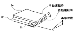
- the movable floor surface 8e attached to the base portion 8b so as to be tiltable in the front-rear direction and the left-right direction, and the movable floor surface 8e for tilting in the front-rear direction.
- An electric actuator 8f and an electric actuator 8g for tilting the moving floor 8e in the left-right direction may be provided.
- the moving floor surface 8e When the content of the automatic driving operation is acceleration, as illustrated in FIGS. 20A to 20B, the moving floor surface 8e is in the forward direction from the reference position (that is, the back side when viewed from the occupant sitting on the seat 7). When the content of the automatic driving operation is decelerating, the moving floor 8e is negative from the reference position (that is, the back side is higher when viewed from the passenger sitting on the seat 7). Rotate to In this way, the occupant can recognize whether the host vehicle 1 is about to accelerate or decelerate.
- angle ⁇ fa for rotating the moving floor 8e at this time also corresponds to the “target position”.
- the moving floor 8e is rotated in the forward direction from the reference position (that is, rightward when viewed from the occupant sitting on the seat 7), and the automatic driving operation is performed.
- the movable floor surface 8a is rotated in the negative direction from the reference position (that is, leftward as viewed from the occupant sitting on the seat 7). In this way, it is possible to make the occupant recognize whether the vehicle 1 is about to steer right or left.
- angle ⁇ fb for rotating the moving floor 8e at this time also corresponds to the “target position”.
- the manner in which the movable floor surfaces 8a and 8e are moved (or rotated) in accordance with the magnitude of the acceleration and the steering amount is various as in the above-described embodiment. It can be.
- the magnitude of the acceleration and the steering amount is proportional to the movement amount of the moving floor surface 8a (or the angles ⁇ fa and ⁇ fb of the moving floor surface 8e). May be.
- the absolute value of acceleration or the steering amount is smaller than a predetermined threshold
- the amount of change in acceleration or steering amount is larger than when the absolute value or steering amount is larger than the predetermined threshold.
- change_quantity of movement amount or angle (theta) fa, (theta) fb).
- the movement amount (or the angles ⁇ fa and ⁇ fb) may be changed stepwise with respect to the acceleration and the steering amount.
- the driver may be notified of acceleration / deceleration or steering by vibrating the moving floor 8e back and forth or left and right.
- the amplitude A for vibrating the moving floor 8e back and forth or right and left, the frequency f for vibrating, and the duration T of vibration may be changed according to the acceleration and the steering amount.
- the occupant's leg sitting on the seat 7 is moved in the same manner as the above-described aspect in which the movable floor surface 8a is moved. May interfere with the steering handle 6.
- the position of the moving floor 8e may be lower than that during manual operation.
- the moving floor 8e may be moved together with the base portion 8b to a position lower than that during manual operation.
- the base portion 8b is supported by driving the electric actuator 8h by pivotally supporting the front side of the base portion 8b (the back side as viewed from the occupant sitting on the seat 7).
- the base portion 8b may be rotated so that the rear side (the front side when viewed from the occupant sitting on the seat 7) is lowered with the front side as the center.
- the armrest 9 may be provided so as to be movable, and the content of the automatic driving operation may be notified in advance by moving the armrest 9.
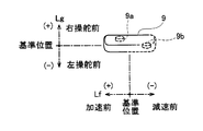
- 21A to 21B illustrate a fifth modification in which the armrest 9 is moved according to the content of the automatic driving operation.
- the armrest 9 of the fifth modification is provided so as to be slidable in the front-rear direction and the left-right direction. Further, as shown in FIG. 21B, an electric actuator 9a for sliding the armrest 9 in the front-rear direction and an electric actuator 9b for sliding the armrest 9 in the left-right direction are mounted inside the armrest 9. Yes.
- the armrest 9 when the content of the automatic driving operation is acceleration, the armrest 9 is moved forward from the reference position, and when the content of the automatic driving operation is deceleration, the armrest is moved. 9 is moved backward from the reference position. In this way, the occupant can recognize whether the host vehicle 1 is about to accelerate or decelerate.
- target position Lf for moving the armrest 9 at this time also corresponds to the “target position”.
- the armrest 9 is moved to the right of the reference position when viewed from the occupant sitting on the seat 7, and the content of the automatic driving operation is left steering. In this case, the armrest 9 is moved to the left from the reference position when viewed from the occupant sitting on the seat 7. In this way, it is possible to make the occupant recognize whether the vehicle 1 is about to steer right or left.
- target position Lg for moving the armrest 9 at this time also corresponds to the “target position”.
- the manner in which the armrest 9 is moved is not limited to the manner in which the armrest 9 is translated as illustrated in FIGS. 21A to 21B, and the armrest 9 may be inclined in the front-rear direction and the left-right direction.
- the armrest 9 is provided so as to be tiltable in the front-rear direction and the left-right direction, and as shown in FIG. 22B, the electric actuator 9c for tilting the armrest 9 in the front-rear direction, It is good also as providing the electric actuator 9d for inclining in the left-right direction.
- the armrest 9 is rotated from the reference position in the positive direction (that is, the direction in which the front side is lowered), and the automatic operation is performed. If the content of is the deceleration, the armrest 9 is rotated in the negative direction (that is, the direction in which the rear side becomes higher) from the reference position. In this way, the occupant can recognize whether the host vehicle 1 is about to accelerate or decelerate.
- angle ⁇ aa for rotating the armrest 9 at this time also corresponds to the “target position”.
- the armrest 9 When the content of the automatic driving operation is right steering, the armrest 9 is rotated in the forward direction from the reference position (that is, the right direction when viewed from the occupant sitting on the seat 7), and the content of the automatic driving operation is In the case of left steering, the armrest 9 is rotated in the negative direction from the reference position (that is, leftward as viewed from the occupant sitting on the seat 7). In this way, it is possible to make the occupant recognize whether the vehicle 1 is about to steer right or left.
- angle ⁇ ab for rotating the armrest 9 at this time also corresponds to the “target position”.
- the manner in which the armrest 9 is moved in the front-rear direction or the left-right direction or the manner in which it is tilted according to the magnitude of the acceleration or the steering amount is various as in the above-described embodiment. It can be set as this aspect.
- the magnitude of the acceleration and the steering amount may be proportional to the movement amount (or angles ⁇ aa and ⁇ ab) of the armrest 9.
- the amount of change in acceleration or steering amount is larger than when the absolute value or steering amount is larger than the predetermined threshold.
- change_quantity of movement amount or angle (theta) aa, (theta) ab).
- the driver may be notified of acceleration / deceleration or steering by vibrating the armrest 9 back and forth or left and right.
- the amplitude A for vibrating the armrest 9 back and forth or left and right, the frequency f for vibrating, and the duration T of vibration may be changed according to the acceleration and the steering amount.
- the driver when a situation that is difficult for the automatic operation control device 100 to occur during automatic operation occurs, the driver must be asked to replace the operation.
- the driver can vibrate at least one of the backrest portion 7b of the seat 7, the lumbar support portions 7R and 7L, the entire seat 7, the headrest 7h, the movable floor surfaces 8a and 8e, and the armrest 9. May be requested to be overridden (that is, the driver performs a driving operation during automatic driving and intervenes in driving to switch the automatic driving state to the manual driving state).
- the angle ⁇ B of the backrest portion 7b of the seat 7 is vibrated at a constant cycle, or the angle ⁇ L of the lumbar support portions 7R, 7L is vibrated at a constant cycle.
- the entire seat 7 is moved back and forth at regular intervals, the headrest 7h, the movable floor 8e and the armrest 9 are rotated forward and backward or left and right at regular intervals, and the movable floor 8a and armrest 9 are moved forward and backward at regular intervals. Or you may vibrate from side to side. Since such a movement is clearly different from a normal automatic driving content notice, the driver can easily recognize that an override is required.
Landscapes
- Engineering & Computer Science (AREA)
- Transportation (AREA)
- Mechanical Engineering (AREA)
- Automation & Control Theory (AREA)
- Aviation & Aerospace Engineering (AREA)
- Human Computer Interaction (AREA)
- Physics & Mathematics (AREA)
- Mathematical Physics (AREA)
- Control Of Driving Devices And Active Controlling Of Vehicle (AREA)
- Traffic Control Systems (AREA)
- Seats For Vehicles (AREA)
- Business, Economics & Management (AREA)
- Health & Medical Sciences (AREA)
- Artificial Intelligence (AREA)
- Evolutionary Computation (AREA)
- Game Theory and Decision Science (AREA)
- Medical Informatics (AREA)
- Radar, Positioning & Navigation (AREA)
- Remote Sensing (AREA)
- General Physics & Mathematics (AREA)
Abstract
車両の周囲の状況に基づいて該車両の運転動作を制御することにより、自動運転を実現する自動運転制御装置(100)を提供する。自動運転制御装置は、車両の周囲の状況に基づいて該車両の運転動作の内容を決定する運転動作決定部(121)と、決定された運転動作の内容に従って、該車両の運転動作を制御する運転動作制御部(122)と、車両の座席(7)に設けられた駆動部を駆動することによって、決定された運転動作の内容を運転情報として出力する運転情報出力部(132)と、を備える。
Description
本出願は、2016年3月14日に出願された日本特許出願番号2016-49864号に基づくもので、その開示をここに参照により援用する。
本開示は、車両の周囲の状況に基づいて車両を自動運転する技術に関する。
今日では、車両が周囲の状況を把握しながら、走行中の車線を維持したり障害物を回避したりすることによって、車両の自動運転を実現する技術が開発されている。自動運転中は、車両に搭載されたコンピューター(以下、運転制御装置)が運転者に代わって車両を運転するので、運転制御装置による運転の仕方(例えばカーブ走行時や、障害物回避時のライン取り、加減速のタイミングや程度など)に運転者が違和感を覚えることがしばしば存在する。
そこで、運転制御装置による運転の仕方を、標準的な運転者による運転の仕方にできるだけ近付けようとする技術が提案されている(たとえば特許文献1)。
しかし、提案されている技術では、自動運転中に乗員に与える違和感を十分に緩和することができないという問題があった。これは、運転の仕方は周囲の状況や運転者の個性などによっても変わるので、運転制御装置による運転の仕方を、車両の乗員が自然と感じる運転の仕方に近付けようとしても限界があるためである。
本開示の目的の一つは、上述の点に鑑みて、車両の乗員に違和感を与えることなく、車両を自動運転することが可能な技術を提供することにある。
本開示の一側面の自動運転制御装置、運転情報出力装置、自動運転制御方法、および運転情報出力方法は、車両の周囲の状況に基づいて車両の運転動作の内容を決定すると、車両の座席に設けられた駆動部を駆動することによって、決定した運転動作の内容を運転情報として出力する。
こうすれば、自動運転動作の内容を、車両の乗員が予め認識することができる。このため、自動運転時の運転の仕方と、乗員が自然と感じる運転の仕方とが異なっていても、乗員に違和感を与えることなく、車両を自動運転することが可能となる。
本開示についての上記および他の目的、特徴や利点は、添付図面を参照した下記の詳細な説明から、より明確になる。図面において、
図1は、本実施例の自動運転制御装置を搭載した自車両の説明図である。
図2は、本実施例の自動運転制御装置の内部構成を示すブロック図である。
図3Aは、シートの背もたれ部を傾けることによって、自車両の加減速を予告する様子を例示した説明図である。
図3Bは、シートの背もたれ部の傾き角度の正負を示した説明図である。
図4Aは、シートのランバーサポート部を傾けることによって、自車両の右操舵あるいは左操舵を予告する様子を例示した説明図である。
図4Bは、シートのランバーサポート部の傾き角度の正負を示した説明図である。
図5は、本実施例の自動運転制御装置が実行する自動運転制御処理の前半部分のフローチャートである。
図6は、自動運転制御処理の後半部分のフローチャートである。
図7Aは、本実施例の自動運転制御装置が自動運転動作の内容を予告する時期や、自動運転動作の開始時期を、衝突時間に基づいて決定する様子を例示した説明図である。
図7Bは、本実施例の自動運転制御装置が自動運転動作の開始を決定する様子を例示した説明図である。
図7Cは、本実施例の自動運転制御装置が自動運転動作の内容を予告を決定する様子を例示した説明図である。
図8Aは、本実施例の自動運転制御装置が自動運転動作の内容を予告する時期や、自動運転動作の開始時期を、地図上の対象物までの距離に基づいて決定する例を示した説明図である。
図8Bは、本実施例の自動運転制御装置が自動運転動作の内容を予告する時期や、自動運転動作の開始時期を、地図上の対象物までの距離に基づいて決定する他の例を示した説明図である。
図9は、シートの背もたれ部の角度θBを自車両1の加速度に応じて変更することによって自動運転動作の内容を予告する様子を例示した説明図である。
図10は、シートのランバーサポート部の角度φLを操舵量に応じて変更することによって自動運転動作の内容を予告する様子を例示した説明図である。
図11Aは、シートの背もたれ部の角度θBあるいはランバーサポート部の角度φLを変更することによって自動運転動作の内容を予告する他の態様を例示した説明図である。
図11Bは、シートの背もたれ部の角度θBあるいはランバーサポート部の角度φLを変更することによって自動運転動作の内容を予告する他の態様を例示した説明図である。
図11Cは、シートの背もたれ部の角度θBあるいはランバーサポート部の角度φLを変更することによって自動運転動作の内容を予告する他の態様を例示した説明図である。
図12Aは、シートの背もたれ部の角度θBあるいはランバーサポート部の角度φLを振動させることによって自動運転動作の内容を予告する他の態様を例示した説明図である。
図12Bは、シートの背もたれ部の角度θBあるいはランバーサポート部の角度φLを振動させることによって自動運転動作の内容を予告する他の態様を例示した説明図である。
図12Cは、シートの背もたれ部の角度θBあるいはランバーサポート部の角度φLを振動させることによって自動運転動作の内容を予告する他の態様を例示した説明図である。
図13は、シートの背もたれ部の角度θBを自車両の目標車速に応じて変更することによって自動運転動作の内容を予告する様子を例示した説明図である。
図14は、シートのランバーサポート部の角度φLを変更することによって自動運転による操舵の内容を予告する様子を例示した説明図である。
図15Aは、シートのランバーサポート部を傾けることによって自動運転による操舵の内容を予告する他の態様における非操舵時を例示した説明図である。
図15Bは、シートのランバーサポート部を傾けることによって自動運転による操舵の内容を予告する他の態様における右操舵時を例示した説明図である。
図15Cは、シートのランバーサポート部を傾けることによって自動運転による操舵の内容を予告する他の態様における左操舵時を例示した説明図である。
図16Aは、シートをスライドさせることによって自動運転動作の内容を予告する他の態様を例示した説明図である。
図16Bは、シートをスライドさせることによって自動運転動作の内容を予告する他の態様を例示した説明図である。
図17は、シートを傾けることによって自動運転動作の内容を予告する他の態様を例示した説明図である。
図18Aは、シートのヘッドレストを移動させることによって自動運転動作の内容を予告する他の態様を例示した説明図である。
図18Bは、シートのヘッドレストを移動させることによって自動運転動作の内容を予告する他の態様を例示した説明図である。
図19Aは、シートの前方に搭載された移動床面を移動させることによって自動運転動作の内容を予告する態様を例示した説明図である。
図19Bは、シートの前方に搭載された移動床面を移動させることによって自動運転動作の内容を予告する態様を例示した説明図である。
図20Aは、シートの前方に搭載された移動床面を移動させることによって自動運転動作の内容を予告する他の態様を例示した説明図である。
図20Bは、シートの前方に搭載された移動床面を移動させることによって自動運転動作の内容を予告する他の態様を例示した説明図である。
図21Aは、シートの側方に搭載されたアームレストを移動させることによって自動運転動作の内容を予告する態様を例示した説明図である。
図21Bは、シートの側方に搭載されたアームレストを移動させることによって自動運転動作の内容を予告する態様を例示した説明図である。
図22Aは、シートの側方に搭載されたアームレストを移動させることによって自動運転動作の内容を予告する他の態様を例示した説明図である。
図22Bは、シートの側方に搭載されたアームレストを移動させることによって自動運転動作の内容を予告する他の態様を例示した説明図である。
図23は、自動運転中に背もたれ部あるいはランバーサポート部を振動させることによって運転者にオーバーライドを要求する動作についての説明図である。
以下では、実施例について説明する。
A.装置構成:
図1には、本実施例の自動運転制御装置100を搭載した自車両1の構成が示されている。本実施例の自車両1には、進行方向の画像を撮影する車載カメラ2や、前方に存在する他車両や障害物を検出するレーダー3や、車輪1wの回転に基づいて車速を検出する車速センサー1tや、自車両1のダッシュボード1d上に搭載されて太陽による日照量を検出する日照センサー1sや、無線によって外部と通信する無線通信器10や、予め設定された目的地への経路を示すナビゲーションシステム(以下、ナビシステム40)や、アクセルペダル4を駆動するアクセルペダルアクチュエーター4mや、ブレーキペダル5を駆動するブレーキペダルアクチュエーター5mや、ステアリングハンドル6を駆動するステアリングハンドルアクチュエーター6mなどが搭載されている。
図1には、本実施例の自動運転制御装置100を搭載した自車両1の構成が示されている。本実施例の自車両1には、進行方向の画像を撮影する車載カメラ2や、前方に存在する他車両や障害物を検出するレーダー3や、車輪1wの回転に基づいて車速を検出する車速センサー1tや、自車両1のダッシュボード1d上に搭載されて太陽による日照量を検出する日照センサー1sや、無線によって外部と通信する無線通信器10や、予め設定された目的地への経路を示すナビゲーションシステム(以下、ナビシステム40)や、アクセルペダル4を駆動するアクセルペダルアクチュエーター4mや、ブレーキペダル5を駆動するブレーキペダルアクチュエーター5mや、ステアリングハンドル6を駆動するステアリングハンドルアクチュエーター6mなどが搭載されている。
尚、ナビゲーションシステムとは、一般に、自車両1の位置を検出する機能と、地図情報を記憶しておく機能と、目的地を設定する機能と、目的地までの経路を検索する機能と、検索した経路を提示して道案内する機能とを備えたシステムを指している。しかし、本実施例の自動運転制御装置100は、ナビシステム40を用いて自車両1の位置を検出し、ナビシステム40に記憶された地図情報を用いて、自車両1の前方の状況を把握できればよく、設定された目的地までの経路を検索して提示する機能は、必ずしも搭載しなくても良い。従って、本実施例のナビシステム40は、一般的なナビゲーションシステムから、目的地を設定する機能や、目的地までの経路を検索する機能や、検索した経路を提示する機能を省いたシステムとすることもできる。
自動運転制御装置100は、車載カメラ2で得られた撮影画像やレーダー3の出力に基づいて自車両1の周囲の状況を検出しながら、ナビシステム40によって示された経路に従って、アクセルペダルアクチュエーター4mや、ブレーキペダルアクチュエーター5m、ステアリングハンドルアクチュエーター6mを駆動することによって自動運転を実行する。尚、本実施例では、説明が複雑になることを回避する目的で、自動運転制御装置100はもっぱら車載カメラ2による撮影画像を用いて周囲の状況を検出し、あるいはレーダー3の出力を用いて周囲の状況を検出するものとして説明するが、図示しないソナーなどを用いて周囲の状況を検出しても良い。
また、ステアリングハンドル6が設けられた運転席側のシート7には、後述するように、背もたれやランバーサポートを移動させるための複数のアクチュエーターが内蔵されており、自動運転制御装置100は、これらアクチュエーターの動きを制御することが可能となっている。
尚、本実施例では、シート7は運転席側のシートであるものとして説明するが、運転席以外(すなわち、助手席や後部座席)のシートであっても構わない。
図2には、本実施例の自動運転制御装置100の大まかな内部構成が示されている。図示されるように、自動運転制御装置100は、自車両1の走行環境に関する種々の情報を取得する走行環境取得モジュール110と、自動運転を実行する自動運転実行モジュール120と、自動運転動作の内容を運転者に予告する運転動作予告モジュール130の大きく3つのモジュールを備えている。尚、自動運転実行モジュール120は、「自動運転制御部」に対応し、運転動作予告モジュール130は、「運転情報出力装置」に対応する。
また、走行環境取得モジュール110には、周囲環境取得部111や、衝突時間算出部112、自車両位置取得部113、地図情報取得部114が設けられている。更に、自動運転実行モジュール120には、運転動作決定部121や、運転動作制御部122が設けられており、運転動作予告モジュール130には、運転情報取得部131や、運転情報出力部132が設けられている。
尚、これらの「モジュール」あるいは「部」は、自動運転制御装置100が、自動運転中の運転動作の内容を運転者に予告するために備える機能に着目して、自動運転制御装置100の内部を便宜的に分類した抽象的な概念である。従って、自動運転制御装置100がこれらの「モジュール」あるいは「部」に物理的に区分されることを表すものではない。これらの「モジュール」あるいは「部」は、CPUで実行されるコンピュータープログラムとして実現することもできるし、LSIやメモリーを含む電子回路として実現することもできるし、更には、これらを組合せることによって実現することもできる。
走行環境取得モジュール110の周囲環境取得部111は、車載カメラ2や、レーダー3、車速センサー1t、日照センサー1s、無線通信器10に接続されている。このうち、車載カメラ2からは撮影画像を取得して、取得した撮影画像を解析することにより、自車両1の前方に存在する他車両や、障害物、歩行者などを検出する。また、レーダー3からは、前方に存在する他車両や、障害物、歩行者などの有無や、自車両1からの距離を検出する。車速センサー1tからは自車両1の速度を取得し、日照センサー1sからは日差しの強さ(すなわち日照量)を取得する。更に、周囲環境取得部111は、無線通信器10を用いて周囲に存在する他車両や、信号機、路側機などと通信することによって、他車両の車速などの情報や、信号機の表示に関する情報、交通状況に関する情報などを取得することもできる。
衝突時間算出部112は、前方に存在する他車両や、歩行者、障害物などについての衝突時間を算出する。尚、衝突時間とは、現状の車速を継続した場合に、前方に存在する他車両や歩行者や障害物など(以下、「前方対象物」と呼ぶ)に衝突するまでの予想時間である。衝突時間は、自車両1から前方対象物までの距離を、自車両1と前方対象物との相対速度で除算することによって求めることができる。
前述したように周囲環境取得部111は、車載カメラ2からの撮影画像やレーダー3の出力に基づいて、前方対象物の有無や前方対象物までの距離を検出することができる。そこで衝突時間算出部112は、周囲環境取得部111で前方対象物が検出されると、前方対象物までの距離を取得する。更に、一定の時間が経過する度に、前方対象物までの距離を取得することによって、その前方対象物と自車両1と相対速度を算出する。そして、こうして求めた相対速度で前方対象物までの距離を除算することによって、前方対象物についての衝突時間を算出する。
尚、前方対象物が他車両の場合は、無線通信器10を用いた車車間通信を行うことによって取得した他車両の車速と、車速センサー1tから得られた自車両1の車速との差を求めることによって、相対速度を算出することも可能である。
自車両位置取得部113は、ナビシステム40に内蔵された自車両位置検出部41から自車両1の現在位置を取得する。自車両位置検出部41は、測位衛星からの信号を受信することによって自車両1の現在位置を検出することができる。
地図情報取得部114は、ナビシステム40に内蔵された地図情報記憶部42から、自車両1の現在位置を含む周辺領域の地図情報を取得する。
尚、自車両1の現在位置と自車両1の周辺領域の地図情報とが分かれば、自車両1の前方に存在するカーブや交差点などまでの距離を知ることができる。そこで、衝突時間算出部112がこれらの情報を取得することによって、前方に存在するカーブや交差点などについての衝突時間を算出するようにしても良い。
自動運転実行モジュール120の運転動作決定部121は、走行環境取得モジュール110の周囲環境取得部111や、衝突時間算出部112、自車両位置取得部113、地図情報取得部114から、上述した各種の情報を取得して、自車両1の運転動作を決定する。ここで、自車両1の運転動作とは、自車両1の加速や減速、左操舵や右操舵といった運転操作の種類に加えて、それら運転操作の操作量を含めた概念である。また、加速または減速の操作量0は現在の速度を維持する運転動作を表し、左操舵または右操舵の操作量0は直進する運転動作を表している。
尚、運転操作の種類および操作量を決定すると、その後の自車両1の挙動(例えば、車速や、加速度や、横方向への加速度や、横方向への速度成分)は予測することができる。そこで、自車両1の運転動作を決定する際には、これらの挙動も含めて、運転動作として決定しても良い。
運転動作制御部122は、運転動作決定部121で決定された運転動作に従って、アクセルペダルアクチュエーター4mや、ブレーキペダルアクチュエーター5m、ステアリングハンドルアクチュエーター6mを制御する。
また、運転動作決定部121は、決定した運転動作を運転動作制御部122に出力するに先立って、運転動作の内容に関する運転情報を、運転動作予告モジュール130の運転情報取得部131に出力する。そして、運転情報取得部131は、受け取った運転情報を運転情報出力部132に出力する。すると、運転情報出力部132は、シート7に内蔵されている後述するアクチュエーターを駆動して、シート7の背もたれやランバーサポートを移動させることにより、運転席側のシート7に座っている乗員(非自動運転時の運転者)に対して、運転情報を提示する。
図3A、図3Bには、本実施例のシート7の背もたれ部7bを傾けることによって、自車両1の加減速を提示する様子が例示されている。図3Aに示すように、シート7の背もたれ部7bが座面部7aに取り付けられる箇所には、電動アクチュエーター7mTが内蔵されている。そして、電動アクチュエーター7mTを駆動することによって、座面部7aに対して背もたれ部7bを傾けることができる。
後述するように、本実施例の自動運転制御装置100は、自車両1を加速させる際には、背もたれ部7bを後方に傾けるように電動アクチュエーター7mTを駆動する。また、自車両1を減速させる際には、背もたれ部7bを前方に傾けるように電動アクチュエーター7mTを駆動する。
尚、図3Bに示すように、背もたれ部7bの角度θBは、背もたれ部7bが後方に傾く場合に「正」となり、前方に傾く場合に「負」となるものとする。
また、本実施例の電動アクチュエーター7mTは、「駆動部」に該当する。
図4A、図4Bには、本実施例のシート7のランバーサポート部7R,7Lを傾けることによって、自車両1の右操舵あるいは左操舵を提示する様子が例示されている。図4Aに示すように、シート7の右側のランバーサポート部7Rには、電動アクチュエーター7mRが内蔵されており、左側のランバーサポート部7Lには、電動アクチュエーター7mLが内蔵されている。そして、電動アクチュエーター7mR,7mLを駆動することによって、左右のランバーサポート部7R,7Lを、背もたれ部7bに対して左右に傾けることができる。
後述するように、本実施例の自動運転制御装置100は、自車両1を右操舵する際には、左右のランバーサポート部7R,7Lを、シート7に座った乗員から見て右方に傾けるように電動アクチュエーター7mR,7mLを駆動する。また、自車両1を左操舵する際には、左右のランバーサポート部7R,7Lを、シート7に座った乗員から見て左方に傾けるように電動アクチュエーター7mR,7mLを駆動する。
尚、図4Bに示すように、ランバーサポート部7R,7Lの角度φLは、ランバーサポート部7R,7Lが右方に傾く場合に「正」となり、左方に傾く場合に「負」となるものとする。
また、本実施例の電動アクチュエーター7mRや、電動アクチュエーター7mLも、「駆動部」に該当する。
本実施例の自動運転制御装置100は、シート7に内蔵された電動アクチュエーター7mTを駆動して背もたれ部7bを傾けることにより、あるいは、電動アクチュエーター7mR,7mLを駆動して左右のランバーサポート部7R,7Lを傾けることによって、シート7に座った乗員に自動運転時の運転情報を提示することができる。その結果、シート7に座った乗員に違和感を与えることなく、自動運転することが可能となっている。以下、こうしたことを実現するために、本実施例の自動運転制御装置100が実行する処理について説明する。
尚、本実施例では、運転席側のシート7の乗員に運転情報を提示するものとして説明するが、運転席以外のシート7に座っている乗員に対して運転情報を提示しても構わない。
B.自動運転制御処理:
図5および図6には、本実施例の自動運転制御装置100が実行する自動運転制御処理のフローチャートが示されている。
図5および図6には、本実施例の自動運転制御装置100が実行する自動運転制御処理のフローチャートが示されている。
図5に示されるように、自動運転制御処理では先ず始めに、自車両1の周囲の状況を取得する(S100)。図2を用いて前述したように、本実施例の自動運転制御装置100は、走行環境取得モジュール110が車載カメラ2や、レーダー3、車速センサー1t、日照センサー1s、無線通信器10に接続されており、これらの出力に基づいて、周囲の状況を取得する。尚、これに限らず、自車両1にソナーなどを搭載しておき、これらを用いて周囲の状況を取得しても良い。
続いて、自車両1の現在位置(以下では、自車両位置と呼ぶこともある)と、自車両位置を含む周囲の地図情報を、ナビシステム40から取得する(S101)。図2を用いて前述したように、走行環境取得モジュール110はナビシステム40にも接続されており、ナビシステム40の自車両位置検出部41からは自車両位置を取得し、地図情報記憶部42からは地図情報を取得することができる。
そして、前方対象物(すなわち、前方に存在する他車両や、歩行者、障害物など)があるか否かを判断する(S102)。前方対象物があるか否かは、車載カメラ2から得られた撮影画像を解析したり、レーダー3の出力を解析したりすることによって判断することができる。
その結果、前方対象物が存在する場合は(S102:yes)、その前方対象物についての衝突時間を算出する(S103)。衝突時間は、自車両1から前方対象物までの距離を、自車両1と前方対象物との相対速度で除算することによって算出することができる。また、自車両1から前方対象物までの距離はレーダー3の出力に基づいて求めることができ、自車両1と前方対象物との相対速度は、前方対象物までの距離の時間変化に基づいて求めることができる。
これに対して、前方対象物が存在しない場合は(S102:no)、衝突時間を算出することなく、自車両1の前方にカーブが存在するか否かを判断する(S104)。カーブが存在するか否かは、地図情報に含まれる道路の形状を取得することによって判断することができる。あるいは、車載カメラ2で撮影した画像を解析し、車線(あるいは白線)を検出することによって、道路形状を取得しても良い。
その結果、前方にカーブが存在する場合は(S104:yes)、カーブの開始位置とカーブの曲率半径を取得する(S105)。カーブの開始位置および曲率半径についても地図情報から取得することができる。あるいは、車載カメラ2による撮影画像から取得した道路形状に基づいて、カーブの開始位置や曲率半径を求めても良い。
一方、自車両1の前方にカーブが存在しない場合は(S104:no)、カーブの開始位置や曲率半径を算出することなく、自車両1の前方に要注意地点が存在するか否かを判断する(S106)。ここで、要注意地点とは、交差点や、トンネル入口やトンネル出口、登り坂の終了地点など、運転者が手動運転する場合に注意が必要となる地点である。すなわち、交差点は事故が起こり易いことが知られているため、運転に注意が必要である。また、トンネル入口やトンネル出口では明るさが急に変化して視界が奪われ易いので、運転に注意が必要となる。更に、登り坂の終了地点では、登り坂から下り坂に切り換わるために見通しが悪くなるため、運転に注意が必要となる。
尚、運転者が手動運転する場合に注意が必要となる要注意地点の存在を、自動運転中に考慮するのは、運転者に違和感を与えることなく自動運転するためである。すなわち、手動運転中の運転者は、これらの要注意地点では半ば反射的に減速したり、低めの車速で走行したりする傾向にある。このため、自動運転中であっても、運転者に違和感を与えることなく自動運転するためには、自車両1の前方に存在する要注意地点を把握しておく必要があるからである。
要注意地点は、ナビシステム40から取得する地図情報に予め記憶されているため、自動運転制御装置100は自車両1の前方に要注意地点が存在するか否かを容易に判断することができる。もちろん、無線通信器10を用いて外部から取得した情報に基づいて、前方の要注意地点の有無を判断しても良い。
また、濃霧や大雪、大雨などで遠くが見通せない場合(すなわち、視程が小さい場合)にも、運転者は半ば反射的に減速したり、低めの車速で走行したりする傾向にある。そこで、車載カメラ2による撮影画像を解析することによって、自車両1の前方方向への視程の程度を検出して、視程の程度が所定値以下となった場合には、要注意地点に差しかかったものと判断しても良い。
あるいは、無線通信器10を介して外部と通信することにより、自車両1の前方で視程が小さい地点が存在か否か、および視程が小さい地点が存在する場合にはその地点までの距離を取得してもよい。そして、自車両1から一定距離以内にそのような地点が存在する場合には、要注意地点が存在するものと判断しても良い。
その結果、前方に要注意地点が存在する場合は(S106:yes)、自車両1から要注意地点までの距離を取得する(S107)。自車両1が存在する位置は分かっているから、要注意地点の位置が分かれば、自車両1から要注意地点までの距離は容易に取得することができる。
これに対して、自車両1の前方に要注意地点が存在しない場合は(S106:no)、要注意地点までの距離を取得することなく、自車両1の乗員に対して警告が必要か否かを判断する(S108)。例えば、S103で算出した衝突時間が所定時間よりも小さかった場合や、S107で取得したカーブの開始位置までの距離や、S109で取得した要注意地点までの距離が所定距離よりも小さかったなどの場合には、警告を要する(S108:yes)と判断する。
その結果、警告が必要と判断した場合は(S108:yes)、左右のランバーサポート部7R,7Lを振動させることによって警告する(S109)。本実施例では、電動アクチュエーター7mL,7mRを互いに逆方向に駆動することによって、左右のランバーサポート部7R,7Lを振動させる。
もちろん、電動アクチュエーター7mL,7mRとは別に、バイブレーターをランバーサポート部7R,7Lに内蔵しておき、バイブレーターを駆動することによってランバーサポート部7R,7Lを振動させても良い。あるいは、シート7の座面部7aにバイブレーターを内蔵しておき、バイブレーターを駆動することによって座面部7aを振動させても良い。
これに対して、警告が不要であった場合は(S108:no)、自動運転動作の内容と自動運転動作の実施時期とを決定する(S110)。例えば、ナビシステム40に対して目的地が設定されている場合には、ナビシステム40によって示された経路の情報と、自車両1の周囲の状況とに基づいて、アクセルペダル4やブレーキペダル5、ステアリングハンドル6を操作するか否か、および操作量を決定する。
また、先行車両を追走するように設定されている場合には、車載カメラ2によって得られた撮影画像に基づいて、あるいはレーダー3の出力に基づいて、先行車両の位置を含めた自車両1の周囲の状況を検出することによって、アクセルペダル4やブレーキペダル5、ステアリングハンドル6を操作するか否か、および操作量を決定する。
例えば、図7Aに示すように、一定速度v1での走行中に、速度v1よりも遅い速度v2で走行する他車両が前方に検出されたものとする。このような場合、自車両1から前方の他車両までの距離がLaとすると、衝突時間TTCaは、TTCa=La/(v1-v2)によって算出することができる。
このような場合、衝突時間TTCbが第1閾値時間th1まで短くなったら、相対速度(=v1-v2)に応じた減速度で減速を開始する旨を決定し(図7B参照)、更に、衝突時間TTCcが第1閾値時間th1よりも大きな第2閾値時間th2まで短くなったら、減速を予告する旨を決定する(図7C参照)。図5の自動運転制御処理のS110では、このように自動運転動作の内容(ここでは減速)と、その自動運転動作の実施時期と、更に予告時期とを決定する。
また、図8Aに示すように、前方にカーブが存在していたとすると、図5のS105ではカーブの開始位置およびカーブの曲率半径が取得されている。カーブに進入する際の適切な車速(以下、進入速度)はカーブの曲率半径に応じて決まるから、曲率半径に応じた進入速度を決定して、自車両1の車速と比較する。
その結果、進入速度よりも自車両1の車速の方が大きかった場合には、カーブの開始位置から距離L1手前の地点で、自車両1の車速と進入速度との速度差に応じた減速度で、減速する旨を決定する。また、減速を開始する地点よりも、更に距離L2手前の地点で、減速を予告する旨を決定する。
あるいは、図8Bに示すように、前方に信号機のない交差点が存在していたとすると、交差点の位置から距離L3手前の地点で、自車両1の車速に応じた減速度で減速して、交差点で停止する旨を決定する。また、減速を開始する地点よりも、更に距離L4手前の地点で、減速を予告する旨を決定する。
図5の自動運転制御処理のS110では、このようにして自動運転動作の内容と、その自動運転動作の実施時期および予告時期を決定する。尚、こうして決定された自動運転動作の内容が、「運転情報」に対応する。
続いて、S110で決定した予告時期になったか否かを判断する(S111)。その結果、予告時期になっていなかった場合は(S111:no)、S111の判断を繰り返すことによって待機状態となる。
そして、予告時期になったと判断したら(S111:yes)、決定した自動運転動作の内容が加速か否かを判断する(図6のS112)。その結果、自動運転動作の内容が加速であった場合は(S112:yes)、加速の程度に応じて電動アクチュエーター7mTを駆動して、シート7の背もたれ部7bを後傾させることによって加速を予告する(S113)。ここで「背もたれ部7bを後傾させる」とは、背もたれ部7bを後ろ向きに倒すように傾けることをいう。
これに対して、自動運転動作の内容が加速ではなかった場合は(S112:no)、減速か否かを判断する(S114)。その結果、減速であった場合は(S114:yes)、減速の程度に応じて電動アクチュエーター7mTを駆動して、シート7の背もたれ部7bを前傾させることによって減速を予告する(S115)。ここで「背もたれ部7bを前傾させる」とは、背もたれ部7bを前向きに起こすように傾けることをいう。
尚、図3A、図3Bには、シート7の背もたれ部7bを傾けることによって、加速あるいは減速を予告する様子が例示されている。
また、自動運転動作の内容が加速でも減速でも無かった場合は(S114:no)、電動アクチュエーター7mTは駆動しない。この結果、シート7の背もたれ部7bは、前後何れの方向にも傾かない状態が保たれる。
続いて、図5のS110で決定した自動運転動作の内容が、ステアリングハンドル6の右方向への操舵(以下、右操舵)か否かを判断する(S116)。その結果、右操舵であった場合は(S116:yes)、ステアリングハンドル6の操舵量に応じて、電動アクチュエーター7mRおよび電動アクチュエーター7mLを駆動して、ランバーサポート部7Rおよびランバーサポート部7Lを右傾させることによって右操舵を予告する(S117)。ここで「右傾させる」とは、シート7に座っている乗員からみて右方向に傾けることを言う。
これに対して、自動運転動作の内容が右操舵ではなかった場合は(S116:no)、ステアリングハンドル6の左方向への操舵(以下、左操舵)か否かを判断する(S118)。その結果、左操舵であった場合は(S118:yes)、操舵量に応じて、電動アクチュエーター7mRおよび電動アクチュエーター7mLを駆動して、ランバーサポート部7Rおよびランバーサポート部7Lを左傾させることによって左操舵を予告する(S119)。ここで「左傾させる」とは、シート7に座っている乗員からみて左方向に傾けることを言う。
図4A、図4Bには、ランバーサポート部7Rおよびランバーサポート部7Lを右傾あるいは左傾させることによって、右操舵あるいは左操舵を予告する様子が例示されている。
また、自動運転動作の内容が右操舵でも左操舵でも無かった場合は(S118:no)、電動アクチュエーター7mRおよび電動アクチュエーター7mLは駆動しない。この結果、ランバーサポート部7Rおよびランバーサポート部7Lは、左右何れの方向にも傾かない状態が保たれる。
以上のようにして、シート7の背もたれ部7bや、ランバーサポート部7R,7Lを傾けると、その動きはシート7に座っている乗員に認識されて、自動運転動作の実行前にその内容を乗員に伝えることができる。このため、シート7に座った乗員は、これから行われる自動運転動作の内容を予め認識することができるので、自動運転に対して違和感を覚えることを回避することが可能となる。
また、シート7の背もたれ部7bや、ランバーサポート部7R,7Lの動きによって自動運転動作の内容を乗員に伝えるので、視覚や聴覚に訴えかけて伝える場合と異なって、乗員が煩わしく感じたり、煩く感じたりすることがない。このため、自動運転中に、逐一の運転動作の内容を伝える場合でも、乗員に負担を与えることなく、自然に伝えることができる。
加えて、自動運転中に乗員の意識がぼんやりしていた場合でも、体の一部(ここでは、背もたれ部7bに触れた背中や、ランバーサポート部7R,7Lに触れた腰の部分)を動かしてやれば、そのことを比較的明確に認識させることができる。更に、認識した動き(ここでは、背もたれ部7bや、ランバーサポート部7R,7Lの動き)が意味する内容は直感的に理解することができるので、意識がぼんやりしている乗員に対しても、自動運転動作の内容を確実に認識させることが可能となる。
また、シート7の背もたれ部7bを傾ける角度θBは、自車両1の加減速に応じて、次のような角度に設定されている。
図9には、加速あるいは減速の程度に応じて設定された背もたれ部7bの角度θBが例示されている。ここで、図3A、図3Bを用いて前述したように、背もたれ部7bの角度θBは、背もたれ部7bを、所定の基準位置から後ろ向きに倒す方向が正となり、基準位置から起こす方向が負となる。
図示されるように、自車両1を加速する際には、背もたれ部7bの角度θBが正の値に設定され、減速する際には、背もたれ部7bの角度θBが負の値に設定される。更に、加速度の絶対値が大きくなるほど、角度θBの絶対値も大きな値に設定される。このため、運転者は背もたれ部7bが前後に傾く動きから、自車両1が加速しようとしているのか、あるいは減速しようとしているのかを認識することができる。更には、背もたれ部7bの角度θBの大きさから、加速や減速の程度を認識することができる。そして、このようにして加速あるいは減速を予告した後は、次に加速あるいは減速を予告する場合に備えて、背もたれ部7bの角度θBを基準位置に戻しておく。このときに背もたれ部7bを戻す速度は、運転者が気付かない程度の小さな速度とすることが望ましい。
尚、このような背もたれ部7bの角度θBは、「目標位置」に該当する。
また、シート7の左右のランバーサポート部7R,7Lを傾ける角度φLは、自車両1の右操舵あるいは左操舵の操舵量に応じて、次のような角度に設定されている。
図10には、自車両1の操舵量に応じて設定されたランバーサポート部7R,7Lの角度φLが例示されている。ここで、図4A、図4Bを用いて前述したように、左右のランバーサポート部7R,7Lを傾ける角度φLは、シート7に座った乗員から見て、所定の基準位置に対して右側に傾ける方向が正となり、左側に傾ける方向が負となる。
図示されるように、自車両1を右操舵する際には、ランバーサポート部7R,7Lの角度φLが正の値に設定され、自車両1を左操舵する際には、ランバーサポート部7R,7Lの角度φLが負の値に設定される。このため、運転者はランバーサポート部7R,7Lが傾く方向から、自車両1が右操舵しようとしているのか、左操舵しようとしているのかを認識することができる。更には、ランバーサポート部7R,7Lの角度φLの絶対値の大きさから、右操舵あるいは左操舵の操舵量も認識することができる。そして、このようにして右操舵あるいは左操舵を予告した後は、次に右操舵あるいは左操舵を予告する場合に備えて、ランバーサポート部7R,7Lの角度φLを基準位置に戻しておく。このときにランバーサポート部7R,7Lを戻す速度は、運転者が気付かない程度の小さな速度とすることが望ましい。
尚、このようなランバーサポート部7R,7Lの角度φLも、「目標位置」に該当する。
図6のS113、S115、S117、S119では、以上のようにして背もたれ部7bや、ランバーサポート部7R,7Lを傾けることによって、図5のS110で決定した自動運転の内容を運転者に予告する。
その後、自動運転制御装置100は、S110で決定した内容に従って、アクセルペダルアクチュエーター4mや、ブレーキペダルアクチュエーター5m、ステアリングハンドルアクチュエーター6mを駆動することによって、自動運転動作を実行する(S121)。
続いて、自動運転制御装置100は自動運転を終了するか否かを判断し(S122)、終了しない場合は(S122:no)、処理の先頭に戻って、自車両1の周囲の状況を取得した後(図5のS100)、続く上述した一連の処理(S101~S122)を実行する。そして、このような操作を繰り返しているうちに、自動運転を終了すると判断した場合は(S122:yes)、図5および図6の自動運転制御処理を終了する。
以上に詳しく説明したように、本実施例の自動運転制御装置100は、自動運転動作の内容を決定すると、その内容に応じて、シート7の背もたれ部7bや、ランバーサポート部7R,7Lを傾ける。こうすれば、自車両1の乗員は、背もたれ部7bや、ランバーサポート部7R,7Lの動きから、自動運転動作の内容を予め認識することができる。このため、たとえ自動運転動作の内容が、乗員にとって自然に感じられる運転の仕方ではなかったとしても、そのことが乗員に違和感を与えることを回避することができる。その結果、自動運転時の運転の仕方と、乗員が自然と感じる運転の仕方とが異なっていても、乗員に違和感を与えることなく、車両を自動運転することが可能となる。
尚、以上では、加速度の絶対値が大きくなるほど、シート7の背もたれ部7bが大きく傾き、操舵量が大きくなるほど、ランバーサポート部7R,7Lが大きく傾くものとして説明した(図9、図10を参照のこと)。
しかし、加速度に応じて背もたれ部7bを傾ける態様や、操舵量に応じてランバーサポート部7R,7Lを傾ける態様には、様々な工夫を凝らすことができる。
例えば、図11Aに実線で例示したように、加速度の絶対値が所定値tha以下の場合と、所定値tha以上の場合とで、加速度に対する背もたれ部7bの角度θBの傾きを異ならせて、所定値tha以下の場合は所定値tha以上の場合よりも傾きを小さくしても良い。
ランバーサポート部7R,7Lの角度φLについても同様に、図中に実線で例示したように、操舵量の絶対値が所定値tha以下の場合と、所定値tha以上の場合とで、操舵量に対するランバーサポート部7R,7Lの角度φLの傾きを異ならせて、所定値tha以下の場合は所定値tha以上の場合よりも傾きを小さくしても良い。
こうすれば、小さな加減速あるいは操舵量では、運転者には背もたれ部7bや、ランバーサポート部7R,7Lの動きが分からないか、あるいは、気にならないようにすることができる。このため、小さな加減速や操舵の度に、背もたれ部7bや、ランバーサポート部7R,7Lが動いて、そのことを運転者が煩わしく感じる虞が生じない。
尚、図11Aでは、加速度あるいは操舵量の絶対値が、所定値thaより小さい範囲でも、角度θBあるいは角度φLが変化するものとして表示しているが、所定値thaより小さい範囲では、角度θBあるいは角度φLが変化しないようにしても構わない。
あるいは、図11Aに破線で例示したように、加速度の絶対値が所定値tha以下の場合は、所定値tha以上の場合よりも、加速度に対する背もたれ部7bの角度θBの傾きが大きくなるようにしても良い。
また、ランバーサポート部7R,7Lの角度φLについても同様に、図中に破線で例示したように、操舵量の絶対値が所定値tha以下の場合は、所定値tha以上の場合よりも、操舵量に対するランバーサポート部7R,7Lの角度φLが大きくなるようにしても良い。
こうすれば、自動運転中に自動運転制御装置100が行う細かな運転動作についての予告も、背もたれ部7bやランバーサポート部7L,7Rの動きによって、運転者が明確に認識することが可能となる。
更には、図11Bに例示したように、所定値thbを境として、加速度の絶対値あるいは操舵量がそれより大きい場合には、背もたれ部7bや、ランバーサポート部7R,7Lを一定角度まで傾けるが、加速度の絶対値あるいは操舵量がそれより小さい場合は、背もたれ部7bや、ランバーサポート部7R,7Lを傾けないこととしても良い。
こうすれば、運転者に予告する必要性が小さな加減速や操舵の場合には、背もたれ部7bや、ランバーサポート部7R,7Lが動かないので運転者が煩わしく感じることがない。また、運転者に予告する必要性が大きな加減速や操舵の場合には、背もたれ部7bや、ランバーサポート部7R,7Lが一定角度で大きく動くので、自車両1が加速あるいは減速しようとしているや、操舵しようとしていることを運転者がハッキリと認識することができる。
また、図11Cに例示したように、背もたれ部7bや、ランバーサポート部7R,7Lを複数段階で傾けるようにしても良い。例えば、自車両1を加速させようとしている場合について説明すると、加速度がthcより大きい場合には背もたれ部7bを一定角度に後傾させるが、加速度が更に大きなthdより大きくなる場合には、更に大きな角度に背もたれ部7bを後傾させてもよい。
自車両1を操舵する場合についても同様に、操舵量がthcより大きい場合にはランバーサポート部7R,7Lを一定角度に傾けるが、操舵量が更に大きなthdより大きくなる場合には、更に大きな角度にランバーサポート部7R,7Lを傾けるようにしてもよい。
こうすれば、運転者は背もたれ部7bや、ランバーサポート部7R,7Lの大まかな動きから、加減速や操舵の程度を大まかに認識することができるので、自動運転の内容を、必要十分な程度で適切に認識することができる。
あるいは、背もたれ部7bや、ランバーサポート部7R,7Lの傾きを振動させることによって、加減速や操舵の程度を運転者に伝えるようにしても良い。
例えば、自車両1を加減速させる場合について説明すると、図12Aに例示したように、自車両1を加速させる場合には、背もたれ部7bを正方向(すなわち後向き)に傾けては、元の角度に戻す動作を繰り返すことによって振動させ、自車両1を減速させる場合には、背もたれ部7bを負方向(すなわち前向き)に起こしては、元の角度の戻す動作を繰り返すことによって振動させる。こうすれば、背もたれ部7bが振動する方向によって、自車両1が加速しようとしているのか、減速しようとしているのかを運転者に認識させることができる。
自車両1を操舵する場合についても同様に、右操舵する場合には、ランバーサポート部7R,7Lを正方向(すなわち右方向)に傾けては元に戻す動作を繰り返することによって、ランバーサポート部7R,7Lを振動させる。また、左操舵する場合には、ランバーサポート部7R,7Lを負方向(すなわち左方向)に傾けては元に戻す動作を繰り返することによって、ランバーサポート部7R,7Lを振動させる。こうすれば、ランバーサポート部7R,7Lが振動する方向によって、自車両1が右操舵しようとしているのか、左操舵しようとしているのかを運転者に認識させることができる。
また、背もたれ部7bや、ランバーサポート部7R,7Lを振動させる振幅Aや、振動させる周波数fや、振動の継続時間Tは、加減速の程度あるいは操舵の程度に応じて変更しても良い。例えば、図12Bに例示したように、加速度あるいは減速度の絶対値が大きくなるほど、振幅Aや、周波数f、継続時間Tの少なくとも1つが大きくなるような態様で、背もたれ部7bを振動させても良い。
あるいは、操舵量が大きくなるほど、振幅Aや、周波数f、継続時間Tの少なくとも1つが大きくなるような態様で、ランバーサポート部7R,7Lを振動させても良い。こうすれば、運転者は、背もたれ部7bや、ランバーサポート部7R,7Lが振動する態様から、加減速や操舵の程度も認識することが可能となる。
更には、加速度の絶対値が単位量変化した時の振幅Aの変化量、あるいは周波数fの変化量や、継続時間Tの変化量を、加速度の絶対値が閾値theより小さい範囲と、閾値theより大きい範囲とで異ならせても良い。操舵量についても同様に、操舵量が単位量変化した時の振幅Aの変化量、あるいは周波数fの変化量や、継続時間Tの変化量を、操舵量が閾値theより小さい範囲と、閾値theより大きい範囲とで異ならせても良い。
すなわち、図12Cに実線で例示したように、加速度については、加速度の絶対値が閾値theより小さい範囲では、閾値theより大きい範囲よりも、加速度の単位量の変化に対する振幅Aや、周波数f、継続時間Tの変化量が小さくなるようにしても良い。また、操舵量についても同様に、操舵量が閾値theより小さい範囲では、閾値theより大きい範囲よりも、操舵量の単位量の変化に対する振幅Aや、周波数f、継続時間Tの変化量が小さくなるようにしても良い。
こうすれば、小さな加減速や操舵では、運転者には背もたれ部7bや、ランバーサポート部7R,7Lの振動が分からないか、あるいは、気にならないようにすることができる。このため、小さな加減速や操舵の度に、背もたれ部7bや、ランバーサポート部7R,7Lが振動して、そのことを運転者が煩わしく感じる虞が生じない。
あるいは、図12Cに破線で例示したように、加速度の絶対値が所定値the以下の場合は、所定値the以上の場合よりも、加速度の単位量の変化に対する振幅Aや、周波数f、継続時間Tの変化量が大きくなるようにしても良い。
また、ランバーサポート部7R,7Lの角度φLについても同様に、図中に破線で例示したように、操舵量の絶対値が所定値the以下の場合は、所定値the以上の場合よりも、操舵量の単位量の変化に対する振幅Aや、周波数f、継続時間Tの変化量が大きくなるようにしても良い。
こうすれば、自動運転中に自動運転制御装置100が行う細かな運転動作についての予告も、背もたれ部7bやランバーサポート部7L,7Rの動きによって、運転者が明確に認識することが可能となる。
あるいは、図13に例示した内容と同様に、背もたれ部7bの角度θBが、自車両1の車速の制御目標値(すなわち目標車速)に応じた角度となるように、背もたれ部7bを傾けることとしても良い。このようにしても、運転者は背もたれ部7bの傾きから目標車速を認識することができる。
もちろん、背もたれ部7bを目標車速に応じて傾ける場合も、加速度に応じて傾ける場合と同様に、目標車速に対して背もたれ部7bを傾ける角度θBは様々な態様に設定することができる。例えば、図11Aを用いて前述した場合と同様に、目標車速の絶対値が所定の閾値よりも小さい場合には、所定の閾値よりも大きい場合よりも、目標車速の変化量に対する角度θBの変化量を小さくしてもよい。あるいは図11Bや図11Cを用いて前述した場合と同様に、目標車速に対して角度θBを段階的に異ならせても良い。
更には、図12A~Cを用いて前述した場合と同様に、背もたれ部7bを振動させることによって、目標車速を変更する旨を運転者に伝えるようにしても良い。このとき、目標車速を増加させる場合には、背もたれ部7bを正方向(すなわち後ろ向き)に振動させ、目標車速を低下させる場合には、背もたれ部7bを負方向(すなわち前向き)に振動させるようにしてもよい。こうすれば、背もたれ部7bが振動する方向によって、目標車速を増加させようとしているのか、低下させようとしているのかを運転者に認識させることができる。
また、背もたれ部7bを振動させる振幅Aや、振動させる周波数fや、振動の継続時間Tは、目標車速に応じて変更しても良い。例えば、図12Bあるいは図12Cに例示した内容と同様に、目標車速の絶対値が大きくなるほど、振幅Aや、周波数f、継続時間Tの少なくとも1つが大きくなるような態様で、背もたれ部7bを振動させても良い。また、このとき、目標車速の絶対値が、所定の閾値の速度よりも小さいか否かによって、目標車速が単位量変化した時の振幅Aの変化量、あるいは周波数fの変化量や、継続時間Tの変化量を異ならせても良い。
更には、図14に例示したように、ランバーサポート部7R,7Lを傾ける角度φLが、自車両1の操舵速度に応じて定められた角度となるように、ランバーサポート部7R,7Lを傾けることとしても良い。このようにしても、運転者はランバーサポート部7R,7Lの傾きから、操舵の方向および操舵速度を認識することができる。
また、操舵速度が決まれば、その操舵によって自車両1に生じる横方向への加速度(以下、横加速度)あるいは横方向への速度(以下、横速度)が決まるから、横加速度あるいは横速度に応じた角度となるように、ランバーサポート部7R,7Lを傾けることとしても良い。このようにしても、運転者はランバーサポート部7R,7Lの傾きから、自車両1がどちらの方向に、どの程度の速さで操舵しようとしているのかを認識することができる。
尚、自動運転制御装置100は自動運転動作の内容を決定するのであって、自車両1の横加速度や横速度を決定しているわけではない。しかし、横加速度や横速度は、自動運転制御装置100が自動運転動作の内容として、操舵量や操舵速度を決定することによって決まるものであるから、間接的には自動運転制御装置100が決定していると考えることもできる。そこで、自動運転制御装置100直接的に決定する操舵量や操舵速度と、間接的に決定する横加速度および横速度とをまとめて、「操舵情報」と称することがあるものとする。
もちろん、ランバーサポート部7R,7Lを操舵速度や、横加速度、横速度に応じて傾ける場合も、操舵量に応じて傾ける場合と同様に、ランバーサポート部7R,7Lを傾ける角度φLは様々な態様に設定することができる。例えば、図11Aを用いて前述した場合と同様に、操舵速度や、横加速度、横速度の絶対値が所定の閾値よりも小さい場合には、所定の閾値よりも大きい場合よりも、操舵速度や、横加速度、横速度の変化量に対する角度φLの変化量を小さくしてもよい。あるいは図11Bや図11Cを用いて前述した場合と同様に、操舵速度や、横加速度、横速度に対して角度φLを段階的に異ならせても良い。
更には、図12A~Cを用いて前述した場合と同様に、ランバーサポート部7R,7Lを振動させることによって、操舵速度や、横加速度、横速度を変更する旨を運転者に伝えるようにしても良い。このとき、操舵速度や、横加速度、横速度を増加させる場合には、ランバーサポート部7R,7Lを正方向(すなわちシート7に座った乗員から見て右向き)に振動させ、操舵速度や、横加速度、横速度を低下させる場合には、ランバーサポート部7R,7Lを負方向(すなわちシート7に座った乗員から見て左向き)に振動させるようにしてもよい。
こうすれば、ランバーサポート部7R,7Lが振動する方向によって、操舵速度や、横加速度、横速度を増加させようとしているのか、低下させようとしているのかを運転者に認識させることができる。
また、ランバーサポート部7R,7Lを振動させる振幅Aや、振動させる周波数fや、振動の継続時間Tは、操舵速度や、横加速度、横速度に応じて変更しても良い。例えば、図12Bあるいは図12Cに例示した内容と同様に、操舵速度や、横加速度、横速度の絶対値が大きくなるほど、振幅Aや、周波数f、継続時間Tの少なくとも1つが大きくなるような態様で、ランバーサポート部7R,7Lを振動させても良い。また、このとき、操舵速度や、横加速度、横速度の絶対値が、所定の閾値の速度よりも小さいか否かによって、目標車速が単位量変化した時の振幅Aの変化量、あるいは周波数fの変化量や、継続時間Tの変化量を異ならせても良い。
更には、シート7のランバーサポート部7R,7Lのように、傾ける部分が複数箇所(ここでは2箇所)ある場合には、それらで分担して、運転動作の内容を予告することとしても良い。
図15A~15Cには、左右のランバーサポート部7R,7Lが分担して、操舵の内容を予告する様子が例示されている。図15A~15Cでは、シート7を上方から見下ろした状態で、左右のランバーサポート部7R,7Lの動きが示されている。また、図中に示した破線は、シート7に座った乗員を表している。
自車両1を操舵しない場合には、図15Aに示したように、右側のランバーサポート部7Rも、左側のランバーサポート部7Lも、基準位置にある。
これに対して、右操舵しようとする時は、図15Bに示したように、右側のランバーサポート部7Rは基準位置のままで、左側のランバーサポート部7Lを正方向(シート7に座った乗員から見て右方向)に傾ける。
こうすれば、右側のランバーサポート部7Rで乗員の右側を支えた状態で、左側のランバーサポート部7Lを傾けて乗員の左側を右方向に押すことになる。このため乗員は、ランバーサポート部7Lが右向きに傾いたことを明確に認識することができ、その結果、自車両1が右操舵しようとしていることを容易に認識することができる。
また、自車両1が左操舵しようとする時は、図15Cに示したように、左側のランバーサポート部7Lは基準位置のままで、右側のランバーサポート部7Rを負方向(シート7に座った乗員から見て左方向)に傾ける。
こうすれば、左側のランバーサポート部7Lで乗員の左側を支えた状態で、右側のランバーサポート部7Rを傾けて乗員の右側を左方向に押すことになる。このため乗員は、ランバーサポート部7Rが左向きに傾いたことを明確に認識することができ、その結果、自車両1が左操舵しようとしていることを容易に認識することが可能となる。
C.変形例:
C-1.第1変形例:
上述した実施例では、シート7に座っている乗員に対して、自動運転動作の内容を認識させるために、シート7の背もたれ部7b、あるいはランバーサポート部7R,7Lを傾けるものとして説明した。しかし、背もたれ部7bや、ランバーサポート部7R,7Lを傾けるのではなく、シート7全体を並進移動させても良い。
C-1.第1変形例:
上述した実施例では、シート7に座っている乗員に対して、自動運転動作の内容を認識させるために、シート7の背もたれ部7b、あるいはランバーサポート部7R,7Lを傾けるものとして説明した。しかし、背もたれ部7bや、ランバーサポート部7R,7Lを傾けるのではなく、シート7全体を並進移動させても良い。
図16A~16Bには、自動運転動作の内容に応じて、シート7を並進移動させる第1変形例が例示されている。
例えば、図16Aでは、シート7が前後方向にスライド可能に設けられており、シート7に内蔵された電動アクチュエーター7mFを駆動することによって、シート7を前後方向に並進移動させることが可能となっている。
尚、本変形例の電動アクチュエーター7mFも、「駆動部」に該当する。
このような第1変形例では、自動運転動作の内容が加速であった場合には、シート7を基準位置よりも正方向(すなわち、シート7に座った乗員から見て前方向)に移動させ、自動運転動作の内容が減速であった場合には、シート7を基準位置よりも負方向(すなわち、シート7に座った乗員から見て後方向)に移動させる。こうすれば、自車両1が加速しようとしているのか、減速しようとしているのかを乗員に認識させることができる。
尚、この時にシート7を移動させる目標位置Laは、「目標位置」に該当する。
あるいは、図16Bに示したように、シート7を左右方向にスライド可能に設けておき、シート7に内蔵された電動アクチュエーター7mSを駆動することによって、シート7を左右方向に並進移動させてもよい。
尚、本変形例の電動アクチュエーター7mSも、「駆動部」に該当する。
このような場合でも、自動運転動作の内容が右操舵であった場合には、シート7を基準位置から正方向(すなわち、シート7に座った乗員から見て右方向)に移動させ、自動運転動作の内容が左操舵であった場合には、シート7を基準位置から負方向(すなわち、シート7に座った乗員から見て左方向)に移動させる。こうすれば、自車両1が右操舵しようとしているのか、左操舵しようとしているのかを乗員に認識させることができる。
また、シート7を左右方向にスライドさせる代わりに、左右方向に回転させるようにしても構わない。
尚、この時にシート7を移動させる目標位置Lb、あるいはシート7を回転させる目標の回転位置も、「目標位置」に該当する。
また、上述した第1変形例で、加速度や操舵量の大きさに応じて、シート7を前後方向あるいは左右方向に移動させる態様は、前述した本実施例と同様に、種々の態様とすることができる。
すなわち、図9や図10を用いて前述した場合と同様に、加速度や操舵量の大きさと、シート7の移動量とが比例するようにしても良い。あるいは、図11Aを用いて前述した場合と同様に、加速度の絶対値や操舵量が所定の閾値よりも小さい場合には、所定の閾値よりも大きい場合よりも、加速度や操舵量の変化量に対する移動量の変化量を小さくしてもよい。若しくは、図11Bや図11Cを用いて前述した場合と同様に、加速度や操舵量に対して移動量を段階的に異ならせても良い。
更には、図12を用いて前述した場合と同様に、シート7全体を前後あるいは左右に振動させることによって、加減速する旨や操舵する旨を運転者に伝えるようにしても良い。この時、シート7全体を前後あるいは左右に振動させる振幅Aや、振動させる周波数fや、振動の継続時間Tは、加速度や操舵量に応じて変更しても良い。
C-2.第2変形例:
また、上述した第1変形例では、シート7全体を並進移動させるものとして説明したが、並進移動させる代わりに、シート7全体を傾けるようにしても良い。
また、上述した第1変形例では、シート7全体を並進移動させるものとして説明したが、並進移動させる代わりに、シート7全体を傾けるようにしても良い。
図17には、自動運転動作の内容に応じて、シート7全体を傾ける第2変形例が例示されている。
図示されるように、第2変形例では、シート7の座面部7aの前側下部に電動アクチュエーター7mKが内蔵されている。そして、電動アクチュエーター7mKを駆動して座面部7aの前側を持ち上げると、座面部7aの後側を回転軸として、シート7全体が傾くようになっている。
尚、本変形例の電動アクチュエーター7mKも、「駆動部」に該当する。
このような第2変形例でも、自動運転動作の内容が加速であった場合には、シート7を基準位置から正方向(すなわち、座面部7aの前方が下がる方向)に回転させ、自動運転動作の内容が減速であった場合には、シート7を基準位置から負方向(すなわち、座面部7aの前方が上がる方向)に回転させる。こうすれば、自車両1が加速しようとしているのか、減速しようとしているのかを乗員に認識させることが可能となる。
尚、この時にシート7を回転させる目標の回転角度θaも、「目標位置」に該当する。
また、上述した第2変形例においても、加速度の大きさに応じて、シート7を回転させる態様は、前述した本実施例と同様に、種々の態様とすることができる。
すなわち、図9を用いて前述した場合と同様に、加速度の大きさと、シート7を回転させた角度とが比例するようにしても良い。あるいは、図11Aを用いて前述した場合と同様に、加速度の絶対値が所定の閾値よりも小さい場合には、所定の閾値よりも大きい場合よりも、加速度の変化量に対する角度の変化量を小さくしてもよい。若しくは、図11Bや図11Cを用いて前述した場合と同様に、加速度に対して、シート7を回転させた角度を段階的に異ならせても良い。
更には、図12を用いて前述した場合と同様に、シート7全体を振動させることによって、加減速する旨を運転者に伝えるようにしても良い。この時、シート7全体を振動させる振幅Aや、振動させる周波数fや、振動の継続時間Tは、加速度に応じて変更しても良い。
C-3.第3変形例:
また、ヘッドレスト7hを移動させることによって、自動運転動作の内容を予告することも可能である。
また、ヘッドレスト7hを移動させることによって、自動運転動作の内容を予告することも可能である。
図18A~18Bには、自動運転動作の内容に応じて、ヘッドレスト7hを移動させる第3変形例が例示されている。
例えば、図18Aでは、ヘッドレスト7hがシート7に対して前後方向に傾くようになっており、シート7に内蔵された電動アクチュエーター7mHを駆動することによって、ヘッドレスト7hを前後方向に傾けることが可能となっている。
このような第3変形例では、自動運転動作の内容が加速であった場合には、ヘッドレスト7hを基準位置から正方向(すなわち、ヘッドレスト7hが前方に移動する方向)に回転させ、自動運転動作の内容が減速であった場合には、ヘッドレスト7hを基準位置から負方向(すなわち、ヘッドレスト7hが後方に移動する方向)に回転させる。こうすれば、自車両1が加速しようとしているのか、減速しようとしているのかを乗員に認識させることができる。
尚、この時にヘッドレスト7hを回転させる目標の回転角度θbも、「目標位置」に該当する。
あるいは、図18Bに示したように、ヘッドレスト7hを左右方向に回転可能に設けておき、7hに内蔵された電動アクチュエーター7mGを駆動することによって、ヘッドレスト7hを左右方向に回転させてもよい。
このような場合、自動運転動作の内容が右操舵であった場合には、ヘッドレスト7hを基準位置から正方向(すなわち、シート7に座った乗員から見て右方向)に回転させ、自動運転動作の内容が左操舵であった場合には、ヘッドレスト7hを基準位置から負方向(すなわち、シート7に座った乗員から見て左方向)に回転させる。こうすれば、自車両1が右操舵しようとしているのか、左操舵しようとしているのかを乗員に認識させることができる。
尚、この時にシート7を回転させる目標も回転角度θcも、「目標位置」に該当する。また、本変形例の電動アクチュエーター7mHや、電動アクチュエーター7mGも、「駆動部」に該当する。
また、上述した第3変形例においても、加速度や操舵量の大きさに応じて、ヘッドレスト7hを前後方向あるいは左右方向に回転させる態様は、前述した本実施例と同様に、種々の態様とすることができる。
すなわち、図9や図10を用いて前述した場合と同様に、加速度や操舵量の大きさと、ヘッドレスト7hを回転させた角度とが比例するようにしても良い。あるいは、図11Aを用いて前述した場合と同様に、加速度の絶対値や操舵量が所定の閾値よりも小さい場合には、所定の閾値よりも大きい場合よりも、加速度や操舵量の変化量に対する角度の変化量を小さくしてもよい。若しくは、図11Bや図11Cを用いて前述した場合と同様に、加速度や操舵量に対して、ヘッドレスト7hを回転させた角度を段階的に異ならせても良い。
更には、図12を用いて前述した場合と同様に、ヘッドレスト7hを前後あるいは左右に振動させることによって、加減速する旨や操舵する旨を運転者に伝えるようにしても良い。この時、ヘッドレスト7hを前後あるいは左右に振動させる振幅Aや、振動させる周波数fや、振動の継続時間Tは、加速度や操舵量に応じて変更しても良い。
C-4.第4変形例:
また、シート7の前方の床面の一部を移動可能に設けておき、この移動可能な床面(以下、移動床面)を移動させることによって、自動運転動作の内容を予告することとしても良い。
また、シート7の前方の床面の一部を移動可能に設けておき、この移動可能な床面(以下、移動床面)を移動させることによって、自動運転動作の内容を予告することとしても良い。
図19A~19Bには、自動運転動作の内容に応じて、移動床面8aを移動させる第4変形例が例示されている。
図19Aに例示したように、第4変形例の移動床面8aは、自車両1の床面に取り付けられた基台部8bに対して、前後方向および左右方向にスライド可能に取り付けられている。そして、移動床面8aは、電動アクチュエーター8cを用いて前後方向にスライドさせることが可能となっており、電動アクチュエーター8dを用いて左右方向にスライドさせることが可能となっている。
尚、本変形例の電動アクチュエーター8cや、電動アクチュエーター8dも、「駆動部」に該当する。
このような第4変形例では、自動運転動作の内容が加速であった場合には、移動床面8aを基準位置から前方向に移動させ、自動運転動作の内容が減速であった場合には、移動床面8aを基準位置から後方向に移動させる。こうすれば、自車両1が加速しようとしているのか、減速しようとしているのかを乗員に認識させることができる。
尚、この時に移動床面8aを移動させる目標位置Ldも、「目標位置」に該当する。
また、自動運転動作の内容が右操舵であった場合には、移動床面8aを、シート7に座った乗員から見て基準位置よりも右方向に移動させ、自動運転動作の内容が左操舵であった場合には、移動床面8aを、シート7に座った乗員から見て基準位置よりも左方向に移動させる。こうすれば、自車両1が右操舵しようとしているのか、左操舵しようとしているのかを乗員に認識させることができる。
尚、この時に移動床面8aを移動させる目標位置Leも、「目標位置」に該当する。
また、上述した第4変形例においても、加速度や操舵量の大きさに応じて、移動床面8aを前後方向あるいは左右方向に移動させる態様は、前述した本実施例と同様に、種々の態様とすることができる。
すなわち、図9や図10を用いて前述した場合と同様に、加速度や操舵量の大きさと、移動床面8aの移動量とが比例するようにしても良い。あるいは、図11Aを用いて前述した場合と同様に、加速度の絶対値や操舵量が所定の閾値よりも小さい場合には、所定の閾値よりも大きい場合よりも、加速度や操舵量の変化量に対する移動量の変化量を小さくしてもよい。若しくは、図11Bや図11Cを用いて前述した場合と同様に、加速度や操舵量に対して移動量を段階的に異ならせても良い。
更には、図12を用いて前述した場合と同様に、移動床面8aを前後あるいは左右に振動させることによって、加減速する旨や操舵する旨を運転者に伝えるようにしても良い。この時、移動床面8aを前後あるいは左右に振動させる振幅Aや、振動させる周波数fや、振動の継続時間Tは、加速度や操舵量に応じて変更しても良い。
尚、第4変形例のように、移動床面8aを移動させる態様では、シート7に座った乗員の脚を動かすことになる。このため、乗員が運転席側のシート7に座っていた場合には、移動床面8aを移動させた時に乗員の膝がステアリングハンドル6に干渉してしまうことが起こり得る。
そこで、自動運転中は、移動床面8aの位置が、手動運転の時に比べて低くなるようにしてもよい。例えば、自動運転を開始するに先立って、移動床面8aを基台部8bごと、手動運転の時よりも低い位置に移動させ、その状態で移動床面8aを移動させることによって、自動運転の内容を乗員に対して予告するようにしても良い。もちろん、基台部8bは動かさずに、移動床面8aを低い位置に移動させるようにしても良い。
あるいは、図19Bに例示したように、基台部8bの前側(シート7に座った乗員から見て奥側)を軸支しておき、電動アクチュエーター8hを駆動することによって、基台部8bの前側を中心に、後側(シート7に座った乗員から見て手前側)が低くなるように基台部8bを回転させてもよい。そして、自動運転から手動運転に復帰する際には、再び電動アクチュエーター8hを駆動することによって、基台部8bを元の位置まで復帰させても良い。
こうすれば、自動運転中は移動床面8aを低い位置に移動させておき、自動運転が終了すると、移動床面8aを元の位置に復帰させることが可能となる。
また、上述した第4変形例では、移動床面8aの移動態様が、前後左右に並進運動する態様であるものとして説明した。しかし、移動床面8aを移動させる態様は並進移動である必要は無く、移動床面8aの移動を運転者が認識可能な態様であれば、種々の態様とすることができる。
例えば、図20A~20Bに例示したように、基台部8bに対して、前後方向および左右方向に傾斜可能に取り付けられた移動床面8eと、移動床面8eを前後方向に傾斜させるための電動アクチュエーター8fと、移動床面8eを左右方向に傾斜させるための電動アクチュエーター8gとを設けることとしても良い。
尚、本変形例の電動アクチュエーター8fや、電動アクチュエーター8gも、「駆動部」に該当する。
そして、自動運転動作の内容が加速であった場合には、図20A~20Bに例示したように、移動床面8eを基準位置から正方向(すなわち、シート7に座った乗員から見て奥側が低くなる方向)に回転させ、自動運転動作の内容が減速であった場合には、移動床面8eを基準位置から負方向(すなわち、シート7に座った乗員から見て奥側が高くなる方向)に回転させる。こうすれば、自車両1が加速しようとしているのか、減速しようとしているのかを乗員に認識させることができる。
尚、この時に移動床面8eを回転させる角度θfaも、「目標位置」に該当する。
また、自動運転動作の内容が右操舵であった場合には、移動床面8eを基準位置から正方向(すなわち、シート7に座った乗員から見て右方向)に回転させ、自動運転動作の内容が左操舵であった場合には、移動床面8aを、基準位置から負方向(すなわち、シート7に座った乗員から見て左方向)に回転させる。こうすれば、自車両1が右操舵しようとしているのか、左操舵しようとしているのかを乗員に認識させることができる。
尚、この時に移動床面8eを回転させる角度θfbも、「目標位置」に該当する。
また、上述した第4変形例においても、加速度や操舵量の大きさに応じて、移動床面8a、8eを移動(あるいは回転)させる態様は、前述した本実施例と同様に、種々の態様とすることができる。
すなわち、図9や図10を用いて前述した場合と同様に、加速度や操舵量の大きさと、移動床面8aの移動量(あるいは移動床面8eの角度θfa、θfb)とが比例するようにしても良い。あるいは、図11Aを用いて前述した場合と同様に、加速度の絶対値や操舵量が所定の閾値よりも小さい場合には、所定の閾値よりも大きい場合よりも、加速度や操舵量の変化量に対する移動量(あるいは角度θfa、θfb)の変化量を小さくしてもよい。若しくは、図11Bや図11Cを用いて前述した場合と同様に、加速度や操舵量に対して移動量(あるいは角度θfa、θfb)を段階的に異ならせても良い。
更には、図12を用いて前述した場合と同様に、移動床面8eを前後あるいは左右に振動させることによって、加減速する旨や操舵する旨を運転者に伝えるようにしても良い。この時、移動床面8eを前後あるいは左右に振動させる振幅Aや、振動させる周波数fや、振動の継続時間Tは、加速度や操舵量に応じて変更しても良い。
加えて、移動床面8eを傾ける態様でも、上述した移動床面8aを移動させる態様と同様に、シート7に座った乗員の脚を動かすことになるので、移動床面8eを傾けた時に乗員の膝がステアリングハンドル6に干渉してしまうことが起こり得る。
そこで、自動運転中は、移動床面8eの位置が、手動運転の時に比べて低くなるようにしてもよい。例えば、移動床面8eを基台部8bごと、手動運転の時よりも低い位置に移動させてもよい。もちろん、基台部8bは動かさずに、移動床面8eを低い位置に移動させるようにしても良い。
更には、図20Bに例示したように、基台部8bの前側(シート7に座った乗員から見て奥側)を軸支しておき、電動アクチュエーター8hを駆動することによって、基台部8bの前側を中心に、後側(シート7に座った乗員から見て手前側)が低くなるように基台部8bを回転させてもよい。
こうすれば、自動運転中は移動床面8eを低い位置に移動させておき、自動運転が終了すると、移動床面8eを元の位置に復帰させることが可能となる。
C-5.第5変形例:
あるいは、アームレスト9を移動可能に設けておき、アームレスト9を移動させることによって、自動運転動作の内容を予告することとしても良い。
あるいは、アームレスト9を移動可能に設けておき、アームレスト9を移動させることによって、自動運転動作の内容を予告することとしても良い。
図21A~21Bには、自動運転動作の内容に応じて、アームレスト9を移動させる第5変形例が例示されている。
図21Aに示されるように、第5変形例のアームレスト9は、前後方向および左右方向にスライド可能に設けられている。また、図21Bに示されるように、アームレスト9の内部には、アームレスト9を前後方向にスライドさせるための電動アクチュエーター9aと、アームレスト9を左右方向にスライドさせるための電動アクチュエーター9bとが搭載されている。
尚、本変形例の電動アクチュエーター9aや、電動アクチュエーター9bも、「駆動部」に該当する。
このような第5変形例では、自動運転動作の内容が加速であった場合には、アームレスト9を基準位置から前方向に移動させ、自動運転動作の内容が減速であった場合には、アームレスト9を基準位置から後方向に移動させる。こうすれば、自車両1が加速しようとしているのか、減速しようとしているのかを乗員に認識させることができる。
尚、この時にアームレスト9を移動させる目標位置Lfも、「目標位置」に該当する。
また、自動運転動作の内容が右操舵であった場合には、アームレスト9を、シート7に座った乗員から見て基準位置よりも右方向に移動させ、自動運転動作の内容が左操舵であった場合には、アームレスト9を、シート7に座った乗員から見て基準位置よりも左方向に移動させる。こうすれば、自車両1が右操舵しようとしているのか、左操舵しようとしているのかを乗員に認識させることができる。
尚、この時にアームレスト9を移動させる目標位置Lgも、「目標位置」に該当する。
また、アームレスト9を移動させる態様は、図21A~21Bに例示したように並進移動させる態様に限られるわけではなく、前後方向および左右方向に傾ける態様とすることもできる。
例えば、図22Aに例示したように、アームレスト9を前後方向および左右方向に傾斜可能に設けておき、図22Bに示すように、アームレスト9を前後方向に傾斜させるための電動アクチュエーター9cと、アームレスト9を左右方向に傾斜させるための電動アクチュエーター9dとを設けることとしても良い。
尚、本変形例の電動アクチュエーター9cや、電動アクチュエーター9dも、「駆動部」に該当する。
そして、自動運転動作の内容が加速であった場合には、図22A~22Bに例示したように、アームレスト9を基準位置から正方向(すなわち、前側が低くなる方向)に回転させ、自動運転動作の内容が減速であった場合には、アームレスト9を基準位置から負方向(すなわち、後側が高くなる方向)に回転させる。こうすれば、自車両1が加速しようとしているのか、減速しようとしているのかを乗員に認識させることができる。
尚、この時にアームレスト9を回転させる角度θaaも、「目標位置」に該当する。
また、自動運転動作の内容が右操舵であった場合には、アームレスト9を基準位置から正方向(すなわち、シート7に座った乗員から見て右方向)に回転させ、自動運転動作の内容が左操舵であった場合には、アームレスト9を基準位置から負方向(すなわち、シート7に座った乗員から見て左方向)に回転させる。こうすれば、自車両1が右操舵しようとしているのか、左操舵しようとしているのかを乗員に認識させることができる。
尚、この時にアームレスト9を回転させる角度θabも、「目標位置」に該当する。
また、上述した第5変形例においても、加速度や操舵量の大きさに応じて、アームレスト9を前後方向あるいは左右方向に移動させる態様、あるいは傾ける態様は、前述した本実施例と同様に、種々の態様とすることができる。
すなわち、図9や図10を用いて前述した場合と同様に、加速度や操舵量の大きさと、アームレスト9の移動量(あるいは角度θaa、θab)とが比例するようにしても良い。あるいは、図11Aを用いて前述した場合と同様に、加速度の絶対値や操舵量が所定の閾値よりも小さい場合には、所定の閾値よりも大きい場合よりも、加速度や操舵量の変化量に対する移動量(あるいは角度θaa、θab)の変化量を小さくしてもよい。若しくは、図11Bや図11Cを用いて前述した場合と同様に、加速度や操舵量に対して移動量(あるいは角度θaa、θab)を段階的に異ならせても良い。
更には、図12を用いて前述した場合と同様に、アームレスト9を前後あるいは左右に振動させることによって、加減速する旨や操舵する旨を運転者に伝えるようにしても良い。この時、アームレスト9を前後あるいは左右に振動させる振幅Aや、振動させる周波数fや、振動の継続時間Tは、加速度や操舵量に応じて変更しても良い。
また、自動運転中に自動運転制御装置100では対応が困難な状況が発生した場合には、運転者に運転を代わって貰わなければならなくなる。このような場合には、シート7の背もたれ部7bや、ランバーサポート部7R,7L、シート7全体、ヘッドレスト7h、移動床面8a,8e、アームレスト9の少なくとも1つを振動させることによって、運転者に対してオーバーライド(すなわち、自動運転中に運転者が運転操作を行って運転に介入することにより、自動運転状態を手動運転状態に切り換えること)を要求しても良い。
例えば図23に示したように、シート7の背もたれ部7bの角度θBを一定周期で振動させたり、あるいはランバーサポート部7R,7Lの角度φLを一定周期で振動させたりする。もちろん、シート7全体を一定周期で前後に移動させたり、ヘッドレスト7hや移動床面8eやアームレスト9を一定周期で前後あるいは左右に回転させたり、移動床面8aや、アームレスト9を一定周期で前後あるいは左右に振動させたりしても良い。このような動きは、通常の自動運転内容の予告とは明らかに違う動きであるため、運転者はオーバーライドが要求されていることを容易に認識することが可能となる。
以上、本実施例および各種の変形例を例示したが、実施例及び変形例は、上記の実施例あるいは各種の変形例に限られるものではない。本開示の技術的思想は、その要旨を逸脱しない範囲において種々の態様で実施することができる。
Claims (42)
- 自車両(1)の周囲の状況に基づいて該自車両の運転動作を制御することにより、自動運転を実現する自動運転制御装置(100)であって、
前記自車両の周囲の状況に基づいて該自車両の運転動作の内容を決定する運転動作決定部(121)と、
前記決定された運転動作の内容に従って、該自車両の運転動作を制御する運転動作制御部(122)と、
前記自車両の座席(7)に設けられた駆動部(7mT、7mR、7mL、7mF、7mS、7mK、7mH、7mG)を駆動することによって、前記決定された運転動作の内容を運転情報として出力する運転情報出力部(132)と
を備える自動運転制御装置。 - 請求項1に記載の自動運転制御装置であって、
前記駆動部は、前記座席の背もたれ部(7b)を駆動する駆動部(7mT)である
自動運転制御装置。 - 請求項1に記載の自動運転制御装置であって、
前記駆動部は、前記座席のランバーサポート部(7R,7L)を駆動する駆動部(7mR、7mL)である
自動運転制御装置。 - 請求項1に記載の自動運転制御装置であって、
前記駆動部は、前記座席のヘッドレスト(7h)を駆動する駆動部(7mH、7mG)である
自動運転制御装置。 - 自車両(1)の周囲の状況に基づいて該自車両の運転動作を制御することにより、自動運転を実現する自動運転制御装置(100)であって、
前記自車両の周囲の状況に基づいて該自車両の運転動作の内容を決定する運転動作決定部(121)と、
前記決定された運転動作の内容に従って、該自車両の運転動作を制御する運転動作制御部(122)と、
前記自車両の座席に対して前方の位置に、移動可能な態様で設けられた移動床面(8a、8e)の駆動部(8c、8d、8f、8g)を駆動して、前記移動床面を移動させることによって、前記決定された運転動作の内容を運転情報として出力する運転情報出力部(132)と
を備える自動運転制御装置。 - 請求項5に記載の自動運転制御装置であって、
前記移動床面は、
前記運転情報出力部は、前記移動床面を移動させて前記運転情報を出力するに先立って、前記移動床面を上下動させる駆動部(8h)を駆動することによって、前記移動床面を手動運転中よりも低い位置に移動させる
自動運転制御装置。 - 自車両(1)の周囲の状況に基づいて該自車両の運転動作を制御することにより、自動運転を実現する自動運転制御装置(100)であって、
前記自車両の周囲の状況に基づいて該自車両の運転動作の内容を決定する運転動作決定部(121)と、
前記決定された運転動作の内容に従って、該自車両の運転動作を制御する運転動作制御部(122)と、
前記自車両の座席に対して側方の位置に、移動可能な態様で設けられたアームレスト(9)の駆動部(9a、9b、9c、9d)を駆動して、前記アームレストを移動させることによって、前記決定された運転動作の内容を運転情報として出力する運転情報出力部(132)と
を備える自動運転制御装置。 - 請求項1ないし請求項7の何れか一項に記載の自動運転制御装置であって、
前方に存在する車両または障害物である前方対象物までの距離と、前記前方対象物と前記自車両との相対速度とを取得して、前記前方対象物に対する衝突時間を算出する衝突時間算出部(112)を備え、
前記運転動作決定部は、所定の第1閾値時間と前記衝突時間とを比較することによって、前記運転動作の実施時期を決定しており、
前記運転情報出力部は、前記第1閾値時間よりも大きな所定の第2閾値時間と前記衝突時間とを比較することによって決定した時期に、前記運転情報を出力する
自動運転制御装置。 - 請求項1ないし請求項8の何れか一項に記載の自動運転制御装置であって、
前記自車両が存在する自車両位置を取得する自車両位置取得部(113)と、
前記自車両位置を含む領域の地図情報を取得する地図情報取得部(114)と
を備え、
前記運転動作決定部は、前記自車両位置と前記地図情報とに基づいて前記運転動作の内容を決定すると共に、該運転動作を実施する前記地図情報上での自車両位置を決定することによって、該運転動作の実施時期を決定しており、
前記運転情報出力部は、前記運転動作を実施する前記地図情報上での自車両位置から手前側に所定距離の位置で、前記運転情報を出力する
自動運転制御装置。 - 請求項1ないし請求項9の何れか一項に記載の自動運転制御装置であって、
前記自車両の周囲環境を取得する周囲環境取得部(111)を備え、
前記運転動作決定部は、前記周囲環境に基づいて、前記運転動作の内容と、該運転動作の実施時期とを決定する
自動運転制御装置。 - 請求項10に記載の自動運転制御装置であって、
前記周囲環境取得部は、前記自車両に搭載された車載カメラ(2)によって得られた撮影画像を解析することによって、前記自車両の前方の道路形状を前記周囲環境として取得しており、
前記運転動作決定部は、前記道路形状に基づいて、前記運転動作の内容および実施時期を決定する
自動運転制御装置。 - 請求項10または請求項11に記載の自動運転制御装置であって、
前記周囲環境取得部は、前記自車両の前方に存在する交差点までの距離を、前記周囲環境として取得しており、
前記運転動作決定部は、前記交差点までの距離に基づいて、前記運転動作の内容および実施時期を決定する
自動運転制御装置。 - 請求項10ないし請求項12の何れか一項に記載の自動運転制御装置であって、
前記周囲環境取得部は、前記自車両の前方に存在するトンネル入口あるいはトンネル出口までの距離を、前記周囲環境として取得しており、
前記運転動作決定部は、前記トンネル入口あるいは前記トンネル出口までの距離に基づいて、前記運転動作の内容および実施時期を決定する
自動運転制御装置。 - 請求項10ないし請求項13の何れか一項に記載の自動運転制御装置であって、
前記周囲環境取得部は、前記自車両の前方に存在する登り坂の終了地点までの距離を、前記周囲環境として取得しており、
前記運転動作決定部は、前記登り坂の終了地点までの距離に基づいて、前記運転動作の内容および実施時期を決定する
自動運転制御装置。 - 請求項10ないし請求項14の何れか一項に記載の自動運転制御装置であって、
前記周囲環境取得部は、前記自車両に搭載された車載カメラ(2)によって得られた撮影画像を解析することによって、前記自車両から前方に向かっての視程の程度を、前記周囲環境として取得しており、
前記運転動作決定部は、前記視程の程度に基づいて、前記運転動作の内容および実施時期を決定する
自動運転制御装置。 - 請求項2、請求項4、請求項5ないし請求項7の何れか一項に記載の自動運転制御装置であって、
前記運転情報出力部は、前記自車両の加速または減速に関する前記運転情報を出力する
自動運転制御装置。 - 請求項16に記載の自動運転制御装置であって、
前記運転情報出力部は、前記自車両の加速または減速の程度に応じて、前記駆動部が駆動する対象物の目標位置を異ならせることによって、前記運転情報を出力する
自動運転制御装置。 - 請求項17に記載の自動運転制御装置であって、
前記運転情報出力部は、前記自車両の加速または減速の程度が所定値よりも小さい範囲では、該所定値よりも大きい範囲よりも、前記加速または減速の程度に対する前記目標位置の変化量が小さな値となるように、前記目標位置を異ならせる
自動運転制御装置。 - 請求項17に記載の自動運転制御装置であって、
前記運転情報出力部は、前記自車両の加速または減速の程度が所定値よりも小さい範囲では、該所定値よりも大きい範囲よりも、前記加速または減速の程度に対する前記目標位置の変化量が大きな値となるように、前記目標位置を異ならせる
自動運転制御装置。 - 請求項17に記載の自動運転制御装置であって、
前記運転情報出力部は、前記自車両の加速また減速の程度と所定の閾値との大小関係に応じて、前記目標位置を異ならせることによって、前記運転情報を出力する
自動運転制御装置。 - 請求項17に記載の自動運転制御装置であって、
前記運転情報出力部は、前記自車両の加速または減速の程度と、複数の前記閾値との大小関係に応じて、前記目標位置を異ならせることによって、前記運転情報を出力する
自動運転制御装置。 - 請求項16に記載の自動運転制御装置であって、
前記運転情報出力部は、前記自車両の加速または減速の程度に応じた態様で、前記駆動部が駆動する対象物を振動させることによって、前記運転情報を出力する
自動運転制御装置。 - 請求項2、請求項4、請求項5ないし請求項7の何れか一項に記載の自動運転制御装置であって、
前記運転情報出力部は、前記自車両の車速に関する前記運転情報を出力する
自動運転制御装置。 - 請求項23に記載の自動運転制御装置であって、
前記運転情報出力部は、前記自車両の目標車速に応じて、前記駆動部が駆動する対象物の目標位置を異ならせることによって、前記運転情報を出力する
自動運転制御装置。 - 請求項23に記載の自動運転制御装置であって、
前記運転情報出力部は、前記自車両の目標車速が所定値よりも小さい範囲では、該所定値よりも大きい範囲よりも、前記目標車速に対する前記目標位置の変化量が小さな値となるように、前記目標位置を異ならせる
自動運転制御装置。 - 請求項23に記載の自動運転制御装置であって、
前記運転情報出力部は、前記自車両の目標車速と所定の閾値との大小関係に応じて、前記目標位置を異ならせることによって、前記運転情報を出力する
自動運転制御装置。 - 請求項26に記載の自動運転制御装置であって、
前記運転情報出力部は、前記自車両の目標車速と、複数の前記閾値との大小関係に応じて、前記目標位置を異ならせることによって、前記運転情報を出力する
自動運転制御装置。 - 請求項23に記載の自動運転制御装置であって、
前記運転情報出力部は、前記自車両の加速または減速の程度に応じた態様で、前記駆動部が駆動する対象物を振動させることによって、前記運転情報を出力する
自動運転制御装置。 - 請求項3ないし請求項7の何れか一項に記載の自動運転制御装置であって、
前記運転情報出力部は、前記自車両の操舵に関する操舵情報を、前記運転情報として出力する
自動運転制御装置。 - 請求項29に記載の自動運転制御装置であって、
前記運転情報出力部は、前記操舵情報の大きさに応じて、前記駆動部が駆動する対象物の目標位置を異ならせることによって、前記運転情報を出力する
自動運転制御装置。 - 請求項30に記載の自動運転制御装置であって、
前記運転情報出力部は、前記操舵情報の大きさが所定値よりも小さい範囲では、該所定値よりも大きい範囲よりも、前記操舵情報の大きさに対する前記目標位置の変化量が小さな値となるように、前記目標位置を異ならせる
自動運転制御装置。 - 請求項30または請求項31に記載の自動運転制御装置であって、
前記運転情報出力部は、前記操舵情報の大きさと所定の閾値との大小関係に応じて、前記目標位置を異ならせることによって、前記運転情報を出力する
自動運転制御装置。 - 請求項32に記載の自動運転制御装置であって、
前記運転情報出力部は、前記操舵情報の大きさと、複数の前記閾値角度との大小関係に応じて前記目標位置を異ならせることによって、前記運転情報を出力する
自動運転制御装置。 - 請求項29に記載の自動運転制御装置であって、
前記運転情報出力部は、前記操舵情報の大きさに応じた態様で、前記駆動部が駆動する対象物を振動させることによって、前記運転情報を出力する
自動運転制御装置。 - 請求項1ないし請求項31の何れか一項に記載の自動運転制御装置であって、
前記運転動作決定部は、前記運転動作の内容に加えて、警告の要否を決定しており、
前記運転情報出力部は、前記警告を要する旨が決定された場合には、前記駆動部が駆動する対象物を振動させることによって前記警告動作を行う
自動運転制御装置。 - 周囲の状況に基づいて自動運転可能な自車両(1)に搭載されて、該自動運転中の運転動作の内容に関する運転情報を該自車両の乗員に対して出力する運転情報出力装置(130)であって、
前記自動運転中に該自車両の運転動作を制御する自動運転制御部(120)から、前記運転情報を取得する運転情報取得部(131)と、
前記自車両の座席(7)に設けられた駆動部(7mT、7mR、7mL、7mF、7mS、7mK、7mH、7mG)を駆動することによって、前記決定された運転動作の内容を運転情報として出力する運転情報出力部(132)と
を備える運転情報出力装置。 - 自車両の周囲の状況に基づいて該車両の運転動作を制御することにより、自動運転を実現する自動運転制御方法であって、
前記自車両の周囲の状況に基づいて該自車両の運転動作の内容を決定する運転動作決定工程(S110)と、
前記自車両の座席(7)に設けられた駆動部(7mT、7mR、7mL、7mF、7mS、7mK、7mH、7mG)を駆動することによって、前記決定された運転動作の内容を運転情報として出力する運転情報出力工程(S113、S115、S117、S119)と、
前記決定された運転動作の内容に従って、該自車両の運転動作を制御する運転動作制御工程(S121)と
を備える自動運転制御方法。 - 周囲の状況に基づいて自動運転可能な自車両に適用されて、該自動運転中の運転動作の内容に関する運転情報を該自車両の乗員に対して出力する運転情報出力方法であって、
前記運転情報を取得する運転情報取得工程(S110)と、
前記自車両の座席(7)に設けられた駆動部(7mT、7mR、7mL、7mF、7mS、7mK、7mH、7mG)を駆動することによって、前記決定された運転動作の内容を運転情報として出力する運転情報出力工程(S113、S115、S117、S119)と
を備える運転情報出力方法。 - 自車両の周囲の状況に基づいて該車両の運転動作を制御することにより、自動運転を実現する自動運転制御方法であって、
前記自車両の周囲の状況に基づいて該自車両の運転動作の内容を決定する運転動作決定工程(S110)と、
前記自車両の座席に対して前方の位置に、移動可能な態様で設けられた移動床面(8a、8e)の駆動部(8c、8d、8g、8g)を駆動して、前記移動床面を移動させることによって、前記決定された運転動作の内容を運転情報として出力する運転情報出力工程(S113、S115、S117、S119)と、
前記決定された運転動作の内容に従って、該自車両の運転動作を制御する運転動作制御工程(S121)と
を備える自動運転制御方法。 - 周囲の状況に基づいて自動運転可能な自車両に適用されて、該自動運転中の運転動作の内容に関する運転情報を該自車両の乗員に対して出力する運転情報出力方法であって、
前記運転情報を取得する運転情報取得工程(S110)と、
前記自車両の座席に対して前方の位置に、移動可能な態様で設けられた移動床面(8a、8e)の駆動部(8c、8d、8f、8g)を駆動して、前記移動床面を移動させることによって、前記決定された運転動作の内容を運転情報として出力する運転情報出力工程(S113、S115、S117、S119)と
を備える運転情報出力方法。 - 自車両の周囲の状況に基づいて該車両の運転動作を制御することにより、自動運転を実現する自動運転制御方法であって、
前記自車両の周囲の状況に基づいて該自車両の運転動作の内容を決定する運転動作決定工程(S110)と、
前記自車両の座席に対して側方の位置に、移動可能な態様で設けられたアームレスト(9)の駆動部(9a、9b、9c、9d)を駆動して、前記移動床面を移動させることによって、前記決定された運転動作の内容を運転情報として出力する運転情報出力工程(S113、S115、S117、S119)と、
前記決定された運転動作の内容に従って、該自車両の運転動作を制御する運転動作制御工程(S121)と
を備える自動運転制御方法。 - 周囲の状況に基づいて自動運転可能な自車両に適用されて、該自動運転中の運転動作の内容に関する運転情報を該自車両の乗員に対して出力する運転情報出力方法であって、
前記運転情報を取得する運転情報取得工程(S110)と、
前記自車両の座席に対して側方の位置に、移動可能な態様で設けられたアームレスト(9)の駆動部(9a、9b、9c、9d)を駆動して、前記移動床面を移動させることによって、前記決定された運転動作の内容を運転情報として出力する運転情報出力工程(S113、S115、S117、S119)と
を備える運転情報出力方法。
Priority Applications (1)
| Application Number | Priority Date | Filing Date | Title |
|---|---|---|---|
| US16/084,386 US20190077419A1 (en) | 2016-03-14 | 2017-01-27 | Autonomous driving control apparatus, driving information output apparatus, autonomous driving control method, and driving information output method |
Applications Claiming Priority (2)
| Application Number | Priority Date | Filing Date | Title |
|---|---|---|---|
| JP2016049864A JP6480366B2 (ja) | 2016-03-14 | 2016-03-14 | 自動運転制御装置、自動運転制御方法、および運転情報出力方法 |
| JP2016-049864 | 2016-03-14 |
Publications (1)
| Publication Number | Publication Date |
|---|---|
| WO2017159064A1 true WO2017159064A1 (ja) | 2017-09-21 |
Family
ID=59850784
Family Applications (1)
| Application Number | Title | Priority Date | Filing Date |
|---|---|---|---|
| PCT/JP2017/002848 Ceased WO2017159064A1 (ja) | 2016-03-14 | 2017-01-27 | 自動運転制御装置、運転情報出力装置、自動運転制御方法、および運転情報出力方法 |
Country Status (3)
| Country | Link |
|---|---|
| US (1) | US20190077419A1 (ja) |
| JP (1) | JP6480366B2 (ja) |
| WO (1) | WO2017159064A1 (ja) |
Cited By (2)
| Publication number | Priority date | Publication date | Assignee | Title |
|---|---|---|---|---|
| WO2023080060A1 (ja) * | 2021-11-03 | 2023-05-11 | 株式会社デンソー | 運転者用車両制御装置および運転者用車両制御方法 |
| JP2023070099A (ja) * | 2021-11-03 | 2023-05-18 | 株式会社デンソー | 運転者用車両制御装置および運転者用車両制御方法 |
Families Citing this family (22)
| Publication number | Priority date | Publication date | Assignee | Title |
|---|---|---|---|---|
| EP3230142B1 (en) * | 2014-12-12 | 2022-03-16 | Sony Group Corporation | Method for switching modes for operating a vehicle |
| DE102016200897A1 (de) * | 2016-01-22 | 2017-07-27 | Bayerische Motoren Werke Aktiengesellschaft | Verfahren und Vorrichtung zum zumindest teilweise automatisierten Fahren |
| JP6686930B2 (ja) * | 2017-02-21 | 2020-04-22 | トヨタ自動車株式会社 | 運転支援装置 |
| US10457165B2 (en) * | 2017-02-27 | 2019-10-29 | Toyota Motor Engineering & Manufacturing North America Inc. | Providing a notification to an occupant using a vehicle seat |
| US10875435B1 (en) * | 2017-03-30 | 2020-12-29 | Zoox, Inc. | Headrest with passenger flaps |
| USD885280S1 (en) | 2017-03-30 | 2020-05-26 | Zoox, Inc. | Vehicle headrest |
| US10843722B2 (en) * | 2017-06-16 | 2020-11-24 | Uatc, Llc | Systems and methods for controlling an input device of an autonomous vehicle |
| US10676085B2 (en) * | 2018-04-11 | 2020-06-09 | Aurora Innovation, Inc. | Training machine learning model based on training instances with: training instance input based on autonomous vehicle sensor data, and training instance output based on additional vehicle sensor data |
| US20210010822A1 (en) * | 2018-04-20 | 2021-01-14 | Mitsubishi Electric Corporation | Notification control device and notification control method |
| TWI674984B (zh) * | 2018-11-15 | 2019-10-21 | 財團法人車輛研究測試中心 | 自動駕駛車輛之行駛軌跡規劃系統及方法 |
| US10471969B1 (en) * | 2019-01-07 | 2019-11-12 | GM Global Technology Operations LLC | System and method to restrict vehicle operations in response to driver impairment |
| US12246742B2 (en) | 2019-09-16 | 2025-03-11 | Volkswagen Aktiengesellschaft | Method and control device for providing feedback to a vehicle occupant |
| US11254286B2 (en) | 2019-09-17 | 2022-02-22 | GM Global Technology Operations LLC | System and method to disable automated driving mode based on vehicle operation context |
| JP7312378B2 (ja) * | 2019-09-26 | 2023-07-21 | スズキ株式会社 | 車両のhmi装置 |
| DE102020111367A1 (de) | 2020-04-27 | 2021-10-28 | Bayerische Motoren Werke Aktiengesellschaft | Verfahren zur Steuerung und zur Regelung einer adaptiven Stützvorrichtung für Insassen eines Kraftfahrzeugs, sowie Bedienvorrichtung, adaptives Stützsystem und Kraftfahrzeug |
| JP2022003358A (ja) * | 2020-06-23 | 2022-01-11 | パイオニア株式会社 | 振動信号生成装置、振動信号生成方法、プログラム及び記憶媒体 |
| US12552295B2 (en) | 2020-08-31 | 2026-02-17 | Ts Tech Co., Ltd. | Vehicle seat |
| JP2022042101A (ja) * | 2020-09-02 | 2022-03-14 | 株式会社東海理化電機製作所 | 呈示装置及び呈示方法 |
| JP2022048538A (ja) * | 2020-09-15 | 2022-03-28 | 株式会社東海理化電機製作所 | 制御装置、制御方法、及びプログラム |
| DE102022202442A1 (de) | 2022-03-11 | 2023-09-14 | Robert Bosch Gesellschaft mit beschränkter Haftung | Einstellvorrichtung und Verfahren zum Einstellen einer Position eines Fahrzeugsitzes eines Fahrzeugs und Verstellsystem für ein Fahrzeug |
| JP7567859B2 (ja) * | 2022-05-19 | 2024-10-16 | トヨタ自動車株式会社 | シート制御装置 |
| JP2024119470A (ja) * | 2023-02-22 | 2024-09-03 | トヨタ自動車株式会社 | 車両用制御装置 |
Citations (7)
| Publication number | Priority date | Publication date | Assignee | Title |
|---|---|---|---|---|
| JPH10338111A (ja) * | 1997-06-05 | 1998-12-22 | Hitachi Ltd | 緊急自動ブレーキ装置 |
| JP2003212071A (ja) * | 2002-01-21 | 2003-07-30 | Denso Corp | 運転者疲労軽減装置 |
| JP2003306107A (ja) * | 2002-04-11 | 2003-10-28 | Nissan Motor Co Ltd | 車両用運転操作補助装置 |
| JP2005119559A (ja) * | 2003-10-17 | 2005-05-12 | Toyota Motor Corp | 車両の乗員姿勢制御装置 |
| JP2007106379A (ja) * | 2005-10-17 | 2007-04-26 | Toyota Motor Corp | 乗員保護装置 |
| JP2015102891A (ja) * | 2013-11-21 | 2015-06-04 | 三菱電機株式会社 | 運転支援装置および運転支援方法 |
| JP2015230573A (ja) * | 2014-06-05 | 2015-12-21 | アルパイン株式会社 | 車両運転支援装置、方法およびプログラム |
-
2016
- 2016-03-14 JP JP2016049864A patent/JP6480366B2/ja not_active Expired - Fee Related
-
2017
- 2017-01-27 US US16/084,386 patent/US20190077419A1/en not_active Abandoned
- 2017-01-27 WO PCT/JP2017/002848 patent/WO2017159064A1/ja not_active Ceased
Patent Citations (7)
| Publication number | Priority date | Publication date | Assignee | Title |
|---|---|---|---|---|
| JPH10338111A (ja) * | 1997-06-05 | 1998-12-22 | Hitachi Ltd | 緊急自動ブレーキ装置 |
| JP2003212071A (ja) * | 2002-01-21 | 2003-07-30 | Denso Corp | 運転者疲労軽減装置 |
| JP2003306107A (ja) * | 2002-04-11 | 2003-10-28 | Nissan Motor Co Ltd | 車両用運転操作補助装置 |
| JP2005119559A (ja) * | 2003-10-17 | 2005-05-12 | Toyota Motor Corp | 車両の乗員姿勢制御装置 |
| JP2007106379A (ja) * | 2005-10-17 | 2007-04-26 | Toyota Motor Corp | 乗員保護装置 |
| JP2015102891A (ja) * | 2013-11-21 | 2015-06-04 | 三菱電機株式会社 | 運転支援装置および運転支援方法 |
| JP2015230573A (ja) * | 2014-06-05 | 2015-12-21 | アルパイン株式会社 | 車両運転支援装置、方法およびプログラム |
Cited By (3)
| Publication number | Priority date | Publication date | Assignee | Title |
|---|---|---|---|---|
| WO2023080060A1 (ja) * | 2021-11-03 | 2023-05-11 | 株式会社デンソー | 運転者用車両制御装置および運転者用車両制御方法 |
| JP2023070099A (ja) * | 2021-11-03 | 2023-05-18 | 株式会社デンソー | 運転者用車両制御装置および運転者用車両制御方法 |
| JP7722324B2 (ja) | 2021-11-03 | 2025-08-13 | 株式会社デンソー | 運転者用車両制御装置および運転者用車両制御方法 |
Also Published As
| Publication number | Publication date |
|---|---|
| JP6480366B2 (ja) | 2019-03-06 |
| JP2017165143A (ja) | 2017-09-21 |
| US20190077419A1 (en) | 2019-03-14 |
Similar Documents
| Publication | Publication Date | Title |
|---|---|---|
| JP6480366B2 (ja) | 自動運転制御装置、自動運転制御方法、および運転情報出力方法 | |
| JP6521803B2 (ja) | 自動運転制御装置、フットレスト、自動運転制御方法、および運転情報出力方法 | |
| JP6753923B2 (ja) | 車両制御システム、車両制御方法、および車両制御プログラム | |
| US20170334451A1 (en) | Vehicle control system, vehicle control method, and medium storing vehicle control program | |
| JP6540983B2 (ja) | 車両制御システム、車両制御方法、および車両制御プログラム | |
| JP2023153852A (ja) | 自動運転制御装置 | |
| US10793163B2 (en) | Vehicle system, vehicle control method, and vehicle control program | |
| CN114026008A (zh) | 车辆的控制系统、车辆的控制方法以及程序 | |
| CN110582439A (zh) | 驾驶辅助方法以及利用了该驾驶辅助方法的驾驶辅助装置、驾驶辅助系统 | |
| JP7133337B2 (ja) | 車両制御装置、車両制御方法、及びプログラム | |
| WO2017187622A1 (ja) | 車両制御システム、車両制御方法、および車両制御プログラム | |
| JP2017185946A (ja) | 車両の自動運転システム | |
| WO2017179193A1 (ja) | 車両制御システム、車両制御方法、および車両制御プログラム | |
| WO2017183077A1 (ja) | 車両制御システム、車両制御方法、および車両制御プログラム | |
| JPWO2018134994A1 (ja) | 車両制御システム、車両制御方法、および車両制御プログラム | |
| JP6758911B2 (ja) | 車両制御システム、車両制御方法、および車両制御プログラム | |
| JP2019156356A (ja) | 車両用制御装置及び車両 | |
| WO2016092773A1 (ja) | 自動運転制御装置、運転情報出力装置、フットレスト、自動運転制御方法、および運転情報出力方法 | |
| CN110281925B (zh) | 行驶控制装置、车辆以及行驶控制方法 | |
| JP6735160B2 (ja) | 車両制御システム、車両制御方法、および車両制御プログラム | |
| JP6885003B2 (ja) | 車両制御装置 | |
| JP7378452B2 (ja) | 車両制御システム、車両制御方法、およびプログラム | |
| CN113615256B (zh) | 控制装置、控制方法以及存储介质 | |
| CN112406886A (zh) | 车辆的控制装置及控制方法、车辆以及存储介质 | |
| KR102894901B1 (ko) | 차량 디스플레이 장치 및 그것의 동작방법 |
Legal Events
| Date | Code | Title | Description |
|---|---|---|---|
| NENP | Non-entry into the national phase |
Ref country code: DE |
|
| 121 | Ep: the epo has been informed by wipo that ep was designated in this application |
Ref document number: 17766072 Country of ref document: EP Kind code of ref document: A1 |
|
| 122 | Ep: pct application non-entry in european phase |
Ref document number: 17766072 Country of ref document: EP Kind code of ref document: A1 |