WO2017158884A1 - ブレーキ装置、ブレーキ制御方法およびモータロック異常判定方法 - Google Patents
ブレーキ装置、ブレーキ制御方法およびモータロック異常判定方法 Download PDFInfo
- Publication number
- WO2017158884A1 WO2017158884A1 PCT/JP2016/076886 JP2016076886W WO2017158884A1 WO 2017158884 A1 WO2017158884 A1 WO 2017158884A1 JP 2016076886 W JP2016076886 W JP 2016076886W WO 2017158884 A1 WO2017158884 A1 WO 2017158884A1
- Authority
- WO
- WIPO (PCT)
- Prior art keywords
- motor
- drive
- terminal voltage
- abnormality determination
- lock abnormality
- Prior art date
- Legal status (The legal status is an assumption and is not a legal conclusion. Google has not performed a legal analysis and makes no representation as to the accuracy of the status listed.)
- Ceased
Links
Images




Classifications
-
- B—PERFORMING OPERATIONS; TRANSPORTING
- B60—VEHICLES IN GENERAL
- B60T—VEHICLE BRAKE CONTROL SYSTEMS OR PARTS THEREOF; BRAKE CONTROL SYSTEMS OR PARTS THEREOF, IN GENERAL; ARRANGEMENT OF BRAKING ELEMENTS ON VEHICLES IN GENERAL; PORTABLE DEVICES FOR PREVENTING UNWANTED MOVEMENT OF VEHICLES; VEHICLE MODIFICATIONS TO FACILITATE COOLING OF BRAKES
- B60T8/00—Arrangements for adjusting wheel-braking force to meet varying vehicular or ground-surface conditions, e.g. limiting or varying distribution of braking force
- B60T8/32—Arrangements for adjusting wheel-braking force to meet varying vehicular or ground-surface conditions, e.g. limiting or varying distribution of braking force responsive to a speed condition, e.g. acceleration or deceleration
- B60T8/88—Arrangements for adjusting wheel-braking force to meet varying vehicular or ground-surface conditions, e.g. limiting or varying distribution of braking force responsive to a speed condition, e.g. acceleration or deceleration with failure responsive means, i.e. means for detecting and indicating faulty operation of the speed responsive control means
- B60T8/92—Arrangements for adjusting wheel-braking force to meet varying vehicular or ground-surface conditions, e.g. limiting or varying distribution of braking force responsive to a speed condition, e.g. acceleration or deceleration with failure responsive means, i.e. means for detecting and indicating faulty operation of the speed responsive control means automatically taking corrective action
- B60T8/94—Arrangements for adjusting wheel-braking force to meet varying vehicular or ground-surface conditions, e.g. limiting or varying distribution of braking force responsive to a speed condition, e.g. acceleration or deceleration with failure responsive means, i.e. means for detecting and indicating faulty operation of the speed responsive control means automatically taking corrective action on a fluid pressure regulator
-
- B—PERFORMING OPERATIONS; TRANSPORTING
- B60—VEHICLES IN GENERAL
- B60T—VEHICLE BRAKE CONTROL SYSTEMS OR PARTS THEREOF; BRAKE CONTROL SYSTEMS OR PARTS THEREOF, IN GENERAL; ARRANGEMENT OF BRAKING ELEMENTS ON VEHICLES IN GENERAL; PORTABLE DEVICES FOR PREVENTING UNWANTED MOVEMENT OF VEHICLES; VEHICLE MODIFICATIONS TO FACILITATE COOLING OF BRAKES
- B60T13/00—Transmitting braking action from initiating means to ultimate brake actuator with power assistance or drive; Brake systems incorporating such transmitting means, e.g. air-pressure brake systems
- B60T13/10—Transmitting braking action from initiating means to ultimate brake actuator with power assistance or drive; Brake systems incorporating such transmitting means, e.g. air-pressure brake systems with fluid assistance, drive, or release
- B60T13/12—Transmitting braking action from initiating means to ultimate brake actuator with power assistance or drive; Brake systems incorporating such transmitting means, e.g. air-pressure brake systems with fluid assistance, drive, or release the fluid being liquid
- B60T13/14—Transmitting braking action from initiating means to ultimate brake actuator with power assistance or drive; Brake systems incorporating such transmitting means, e.g. air-pressure brake systems with fluid assistance, drive, or release the fluid being liquid using accumulators or reservoirs fed by pumps
- B60T13/142—Systems with master cylinder
- B60T13/145—Master cylinder integrated or hydraulically coupled with booster
- B60T13/146—Part of the system directly actuated by booster pressure
-
- B—PERFORMING OPERATIONS; TRANSPORTING
- B60—VEHICLES IN GENERAL
- B60T—VEHICLE BRAKE CONTROL SYSTEMS OR PARTS THEREOF; BRAKE CONTROL SYSTEMS OR PARTS THEREOF, IN GENERAL; ARRANGEMENT OF BRAKING ELEMENTS ON VEHICLES IN GENERAL; PORTABLE DEVICES FOR PREVENTING UNWANTED MOVEMENT OF VEHICLES; VEHICLE MODIFICATIONS TO FACILITATE COOLING OF BRAKES
- B60T13/00—Transmitting braking action from initiating means to ultimate brake actuator with power assistance or drive; Brake systems incorporating such transmitting means, e.g. air-pressure brake systems
- B60T13/10—Transmitting braking action from initiating means to ultimate brake actuator with power assistance or drive; Brake systems incorporating such transmitting means, e.g. air-pressure brake systems with fluid assistance, drive, or release
- B60T13/66—Electrical control in fluid-pressure brake systems
- B60T13/662—Electrical control in fluid-pressure brake systems characterised by specified functions of the control system components
-
- B—PERFORMING OPERATIONS; TRANSPORTING
- B60—VEHICLES IN GENERAL
- B60T—VEHICLE BRAKE CONTROL SYSTEMS OR PARTS THEREOF; BRAKE CONTROL SYSTEMS OR PARTS THEREOF, IN GENERAL; ARRANGEMENT OF BRAKING ELEMENTS ON VEHICLES IN GENERAL; PORTABLE DEVICES FOR PREVENTING UNWANTED MOVEMENT OF VEHICLES; VEHICLE MODIFICATIONS TO FACILITATE COOLING OF BRAKES
- B60T13/00—Transmitting braking action from initiating means to ultimate brake actuator with power assistance or drive; Brake systems incorporating such transmitting means, e.g. air-pressure brake systems
- B60T13/10—Transmitting braking action from initiating means to ultimate brake actuator with power assistance or drive; Brake systems incorporating such transmitting means, e.g. air-pressure brake systems with fluid assistance, drive, or release
- B60T13/66—Electrical control in fluid-pressure brake systems
- B60T13/68—Electrical control in fluid-pressure brake systems by electrically-controlled valves
- B60T13/686—Electrical control in fluid-pressure brake systems by electrically-controlled valves in hydraulic systems or parts thereof
-
- B—PERFORMING OPERATIONS; TRANSPORTING
- B60—VEHICLES IN GENERAL
- B60T—VEHICLE BRAKE CONTROL SYSTEMS OR PARTS THEREOF; BRAKE CONTROL SYSTEMS OR PARTS THEREOF, IN GENERAL; ARRANGEMENT OF BRAKING ELEMENTS ON VEHICLES IN GENERAL; PORTABLE DEVICES FOR PREVENTING UNWANTED MOVEMENT OF VEHICLES; VEHICLE MODIFICATIONS TO FACILITATE COOLING OF BRAKES
- B60T17/00—Component parts, details, or accessories of power brake systems not covered by groups B60T8/00, B60T13/00 or B60T15/00, or presenting other characteristic features
- B60T17/02—Arrangements of pumps or compressors, or control devices therefor
-
- B—PERFORMING OPERATIONS; TRANSPORTING
- B60—VEHICLES IN GENERAL
- B60T—VEHICLE BRAKE CONTROL SYSTEMS OR PARTS THEREOF; BRAKE CONTROL SYSTEMS OR PARTS THEREOF, IN GENERAL; ARRANGEMENT OF BRAKING ELEMENTS ON VEHICLES IN GENERAL; PORTABLE DEVICES FOR PREVENTING UNWANTED MOVEMENT OF VEHICLES; VEHICLE MODIFICATIONS TO FACILITATE COOLING OF BRAKES
- B60T17/00—Component parts, details, or accessories of power brake systems not covered by groups B60T8/00, B60T13/00 or B60T15/00, or presenting other characteristic features
- B60T17/18—Safety devices; Monitoring
- B60T17/22—Devices for monitoring or checking brake systems; Signal devices
- B60T17/221—Procedure or apparatus for checking or keeping in a correct functioning condition of brake systems
-
- B—PERFORMING OPERATIONS; TRANSPORTING
- B60—VEHICLES IN GENERAL
- B60T—VEHICLE BRAKE CONTROL SYSTEMS OR PARTS THEREOF; BRAKE CONTROL SYSTEMS OR PARTS THEREOF, IN GENERAL; ARRANGEMENT OF BRAKING ELEMENTS ON VEHICLES IN GENERAL; PORTABLE DEVICES FOR PREVENTING UNWANTED MOVEMENT OF VEHICLES; VEHICLE MODIFICATIONS TO FACILITATE COOLING OF BRAKES
- B60T7/00—Brake-action initiating means
- B60T7/12—Brake-action initiating means for automatic initiation; for initiation not subject to will of driver or passenger
-
- B—PERFORMING OPERATIONS; TRANSPORTING
- B60—VEHICLES IN GENERAL
- B60T—VEHICLE BRAKE CONTROL SYSTEMS OR PARTS THEREOF; BRAKE CONTROL SYSTEMS OR PARTS THEREOF, IN GENERAL; ARRANGEMENT OF BRAKING ELEMENTS ON VEHICLES IN GENERAL; PORTABLE DEVICES FOR PREVENTING UNWANTED MOVEMENT OF VEHICLES; VEHICLE MODIFICATIONS TO FACILITATE COOLING OF BRAKES
- B60T8/00—Arrangements for adjusting wheel-braking force to meet varying vehicular or ground-surface conditions, e.g. limiting or varying distribution of braking force
- B60T8/17—Using electrical or electronic regulation means to control braking
-
- B—PERFORMING OPERATIONS; TRANSPORTING
- B60—VEHICLES IN GENERAL
- B60T—VEHICLE BRAKE CONTROL SYSTEMS OR PARTS THEREOF; BRAKE CONTROL SYSTEMS OR PARTS THEREOF, IN GENERAL; ARRANGEMENT OF BRAKING ELEMENTS ON VEHICLES IN GENERAL; PORTABLE DEVICES FOR PREVENTING UNWANTED MOVEMENT OF VEHICLES; VEHICLE MODIFICATIONS TO FACILITATE COOLING OF BRAKES
- B60T8/00—Arrangements for adjusting wheel-braking force to meet varying vehicular or ground-surface conditions, e.g. limiting or varying distribution of braking force
- B60T8/32—Arrangements for adjusting wheel-braking force to meet varying vehicular or ground-surface conditions, e.g. limiting or varying distribution of braking force responsive to a speed condition, e.g. acceleration or deceleration
- B60T8/34—Arrangements for adjusting wheel-braking force to meet varying vehicular or ground-surface conditions, e.g. limiting or varying distribution of braking force responsive to a speed condition, e.g. acceleration or deceleration having a fluid pressure regulator responsive to a speed condition
- B60T8/40—Arrangements for adjusting wheel-braking force to meet varying vehicular or ground-surface conditions, e.g. limiting or varying distribution of braking force responsive to a speed condition, e.g. acceleration or deceleration having a fluid pressure regulator responsive to a speed condition comprising an additional fluid circuit including fluid pressurising means for modifying the pressure of the braking fluid, e.g. including wheel driven pumps for detecting a speed condition, or pumps which are controlled by means independent of the braking system
-
- B—PERFORMING OPERATIONS; TRANSPORTING
- B60—VEHICLES IN GENERAL
- B60T—VEHICLE BRAKE CONTROL SYSTEMS OR PARTS THEREOF; BRAKE CONTROL SYSTEMS OR PARTS THEREOF, IN GENERAL; ARRANGEMENT OF BRAKING ELEMENTS ON VEHICLES IN GENERAL; PORTABLE DEVICES FOR PREVENTING UNWANTED MOVEMENT OF VEHICLES; VEHICLE MODIFICATIONS TO FACILITATE COOLING OF BRAKES
- B60T8/00—Arrangements for adjusting wheel-braking force to meet varying vehicular or ground-surface conditions, e.g. limiting or varying distribution of braking force
- B60T8/32—Arrangements for adjusting wheel-braking force to meet varying vehicular or ground-surface conditions, e.g. limiting or varying distribution of braking force responsive to a speed condition, e.g. acceleration or deceleration
- B60T8/88—Arrangements for adjusting wheel-braking force to meet varying vehicular or ground-surface conditions, e.g. limiting or varying distribution of braking force responsive to a speed condition, e.g. acceleration or deceleration with failure responsive means, i.e. means for detecting and indicating faulty operation of the speed responsive control means
- B60T8/885—Arrangements for adjusting wheel-braking force to meet varying vehicular or ground-surface conditions, e.g. limiting or varying distribution of braking force responsive to a speed condition, e.g. acceleration or deceleration with failure responsive means, i.e. means for detecting and indicating faulty operation of the speed responsive control means using electrical circuitry
-
- B—PERFORMING OPERATIONS; TRANSPORTING
- B60—VEHICLES IN GENERAL
- B60T—VEHICLE BRAKE CONTROL SYSTEMS OR PARTS THEREOF; BRAKE CONTROL SYSTEMS OR PARTS THEREOF, IN GENERAL; ARRANGEMENT OF BRAKING ELEMENTS ON VEHICLES IN GENERAL; PORTABLE DEVICES FOR PREVENTING UNWANTED MOVEMENT OF VEHICLES; VEHICLE MODIFICATIONS TO FACILITATE COOLING OF BRAKES
- B60T8/00—Arrangements for adjusting wheel-braking force to meet varying vehicular or ground-surface conditions, e.g. limiting or varying distribution of braking force
- B60T8/32—Arrangements for adjusting wheel-braking force to meet varying vehicular or ground-surface conditions, e.g. limiting or varying distribution of braking force responsive to a speed condition, e.g. acceleration or deceleration
- B60T8/88—Arrangements for adjusting wheel-braking force to meet varying vehicular or ground-surface conditions, e.g. limiting or varying distribution of braking force responsive to a speed condition, e.g. acceleration or deceleration with failure responsive means, i.e. means for detecting and indicating faulty operation of the speed responsive control means
- B60T8/90—Arrangements for adjusting wheel-braking force to meet varying vehicular or ground-surface conditions, e.g. limiting or varying distribution of braking force responsive to a speed condition, e.g. acceleration or deceleration with failure responsive means, i.e. means for detecting and indicating faulty operation of the speed responsive control means using a simulated speed signal to test speed responsive control means
-
- H—ELECTRICITY
- H02—GENERATION; CONVERSION OR DISTRIBUTION OF ELECTRIC POWER
- H02H—EMERGENCY PROTECTIVE CIRCUIT ARRANGEMENTS
- H02H7/00—Emergency protective circuit arrangements specially adapted for specific types of electric machines or apparatus or for sectionalised protection of cable or line systems, and effecting automatic switching in the event of an undesired change from normal working conditions
- H02H7/08—Emergency protective circuit arrangements specially adapted for specific types of electric machines or apparatus or for sectionalised protection of cable or line systems, and effecting automatic switching in the event of an undesired change from normal working conditions for dynamo-electric motors
- H02H7/093—Emergency protective circuit arrangements specially adapted for specific types of electric machines or apparatus or for sectionalised protection of cable or line systems, and effecting automatic switching in the event of an undesired change from normal working conditions for dynamo-electric motors against increase beyond, or decrease below, a predetermined level of rotational speed
-
- B—PERFORMING OPERATIONS; TRANSPORTING
- B60—VEHICLES IN GENERAL
- B60T—VEHICLE BRAKE CONTROL SYSTEMS OR PARTS THEREOF; BRAKE CONTROL SYSTEMS OR PARTS THEREOF, IN GENERAL; ARRANGEMENT OF BRAKING ELEMENTS ON VEHICLES IN GENERAL; PORTABLE DEVICES FOR PREVENTING UNWANTED MOVEMENT OF VEHICLES; VEHICLE MODIFICATIONS TO FACILITATE COOLING OF BRAKES
- B60T13/00—Transmitting braking action from initiating means to ultimate brake actuator with power assistance or drive; Brake systems incorporating such transmitting means, e.g. air-pressure brake systems
- B60T13/10—Transmitting braking action from initiating means to ultimate brake actuator with power assistance or drive; Brake systems incorporating such transmitting means, e.g. air-pressure brake systems with fluid assistance, drive, or release
- B60T13/66—Electrical control in fluid-pressure brake systems
- B60T13/665—Electrical control in fluid-pressure brake systems the systems being specially adapted for transferring two or more command signals, e.g. railway systems
-
- B—PERFORMING OPERATIONS; TRANSPORTING
- B60—VEHICLES IN GENERAL
- B60T—VEHICLE BRAKE CONTROL SYSTEMS OR PARTS THEREOF; BRAKE CONTROL SYSTEMS OR PARTS THEREOF, IN GENERAL; ARRANGEMENT OF BRAKING ELEMENTS ON VEHICLES IN GENERAL; PORTABLE DEVICES FOR PREVENTING UNWANTED MOVEMENT OF VEHICLES; VEHICLE MODIFICATIONS TO FACILITATE COOLING OF BRAKES
- B60T2270/00—Further aspects of brake control systems not otherwise provided for
- B60T2270/40—Failsafe aspects of brake control systems
- B60T2270/406—Test-mode; Self-diagnosis
-
- B—PERFORMING OPERATIONS; TRANSPORTING
- B60—VEHICLES IN GENERAL
- B60T—VEHICLE BRAKE CONTROL SYSTEMS OR PARTS THEREOF; BRAKE CONTROL SYSTEMS OR PARTS THEREOF, IN GENERAL; ARRANGEMENT OF BRAKING ELEMENTS ON VEHICLES IN GENERAL; PORTABLE DEVICES FOR PREVENTING UNWANTED MOVEMENT OF VEHICLES; VEHICLE MODIFICATIONS TO FACILITATE COOLING OF BRAKES
- B60T2270/00—Further aspects of brake control systems not otherwise provided for
- B60T2270/40—Failsafe aspects of brake control systems
- B60T2270/414—Power supply failure
-
- B—PERFORMING OPERATIONS; TRANSPORTING
- B60—VEHICLES IN GENERAL
- B60T—VEHICLE BRAKE CONTROL SYSTEMS OR PARTS THEREOF; BRAKE CONTROL SYSTEMS OR PARTS THEREOF, IN GENERAL; ARRANGEMENT OF BRAKING ELEMENTS ON VEHICLES IN GENERAL; PORTABLE DEVICES FOR PREVENTING UNWANTED MOVEMENT OF VEHICLES; VEHICLE MODIFICATIONS TO FACILITATE COOLING OF BRAKES
- B60T8/00—Arrangements for adjusting wheel-braking force to meet varying vehicular or ground-surface conditions, e.g. limiting or varying distribution of braking force
- B60T8/32—Arrangements for adjusting wheel-braking force to meet varying vehicular or ground-surface conditions, e.g. limiting or varying distribution of braking force responsive to a speed condition, e.g. acceleration or deceleration
- B60T8/34—Arrangements for adjusting wheel-braking force to meet varying vehicular or ground-surface conditions, e.g. limiting or varying distribution of braking force responsive to a speed condition, e.g. acceleration or deceleration having a fluid pressure regulator responsive to a speed condition
- B60T8/48—Arrangements for adjusting wheel-braking force to meet varying vehicular or ground-surface conditions, e.g. limiting or varying distribution of braking force responsive to a speed condition, e.g. acceleration or deceleration having a fluid pressure regulator responsive to a speed condition connecting the brake actuator to an alternative or additional source of fluid pressure, e.g. traction control systems
- B60T8/4809—Traction control, stability control, using both the wheel brakes and other automatic braking systems
- B60T8/4827—Traction control, stability control, using both the wheel brakes and other automatic braking systems in hydraulic brake systems
- B60T8/4863—Traction control, stability control, using both the wheel brakes and other automatic braking systems in hydraulic brake systems closed systems
- B60T8/4872—Traction control, stability control, using both the wheel brakes and other automatic braking systems in hydraulic brake systems closed systems pump-back systems
-
- H—ELECTRICITY
- H02—GENERATION; CONVERSION OR DISTRIBUTION OF ELECTRIC POWER
- H02H—EMERGENCY PROTECTIVE CIRCUIT ARRANGEMENTS
- H02H7/00—Emergency protective circuit arrangements specially adapted for specific types of electric machines or apparatus or for sectionalised protection of cable or line systems, and effecting automatic switching in the event of an undesired change from normal working conditions
- H02H7/08—Emergency protective circuit arrangements specially adapted for specific types of electric machines or apparatus or for sectionalised protection of cable or line systems, and effecting automatic switching in the event of an undesired change from normal working conditions for dynamo-electric motors
Definitions
- the present invention relates to a brake device, a brake control method, and a motor lock abnormality determination method.
- Patent Document 1 discloses a method of determining whether there is a lock abnormality in a motor that drives a pump in a brake device.
- the motor is driven at an on-duty ratio of 100% to detect whether there is a lock abnormality only when the motor is driven at an on-duty ratio lower than 100% for a certain period of time and it is not determined that there is no lock abnormality at the end of the drive. Judgment.
- An object of the present invention is to provide a brake device, a brake control method, and a motor lock abnormality determination method that can reduce motor drive noise during motor self-diagnosis regardless of the situation.
- the brake device repeats the on / off drive a plurality of times so that the motor rotational speed at the time of off does not become zero, and the peak of the motor rotational speed becomes higher as the power is turned on later.
- the motor is driven, and the presence or absence of a motor lock abnormality is determined based on the terminal voltage characteristics when the on / off drive is off.
- FIG. 1 is a system configuration diagram showing a braking / driving system of a vehicle to which a brake device of Embodiment 1 is applied.
- FIG. 2 is a hydraulic circuit diagram of the brake device according to the first embodiment.
- 1 is a configuration diagram of a motor drive circuit according to a first embodiment.
- 3 is a flowchart illustrating a flow of a motor lock abnormality determination process according to the first embodiment.
- 6 is a time chart illustrating an operation when motor lock is not generated in the motor lock abnormality determination process of the first embodiment.
- 6 is a time chart illustrating an operation when a motor lock is generated in the motor lock abnormality determination process of the first embodiment.
- 6 is a flowchart illustrating a flow of motor lock abnormality determination processing according to the second embodiment.
- FIG. 1 is a system configuration diagram showing a braking / driving system of a vehicle to which a brake device of Embodiment 1 is applied.
- FIG. 2 is a hydraulic circuit diagram of the brake device according to
- FIG. 6 is a configuration diagram of a motor drive circuit according to a third embodiment.
- 10 is a flowchart illustrating a flow of motor electrical abnormality determination processing according to the third embodiment.
- 10 is a time chart illustrating an operation when no motor electrical abnormality has occurred in the motor lock abnormality determination process and the motor electrical abnormality determination process of the third embodiment.
- 10 is a time chart illustrating an operation when a motor electrical abnormality occurs in the motor lock abnormality determination process and the motor electrical abnormality determination process of the third embodiment.
- FIG. 1 is a system configuration diagram illustrating a braking / driving system of a vehicle to which the brake device of the first embodiment is applied.
- the brake device of Embodiment 1 is applied to an engine vehicle.
- the brake device applies friction braking force by hydraulic pressure to each wheel of the vehicle (left front wheel FL, right front wheel FR, left rear wheel RL, right rear wheel RR).
- Each wheel FR to RR is provided with a brake operation unit BU.
- the brake operation unit BU is a braking force generator including the wheel cylinder W / C.
- the brake operation unit BU is, for example, a disk type and has a caliper (hydraulic brake caliper).
- the caliper includes a brake disc and a brake pad.
- the brake disc is a brake rotor that rotates integrally with the tire.
- the brake pad is disposed with a predetermined clearance with respect to the brake disc, and moves by the hydraulic pressure of the wheel cylinder W / C to contact the brake disc.
- a friction braking force is generated when the brake pad contacts the brake disc.
- Engine E is connected to front drive shafts FDS (FL) and FDS (FR) of front left and right FL and FR via automatic transmission AT and differential gear DG, respectively, and front wheel left and right based on commands from engine control unit ECU Apply driving force to FL and FR.
- the engine control unit ECU determines the fuel injection amount and ignition timing of the engine E based on operating conditions such as the engine speed from the engine speed sensor 99, the intake air amount, the coolant temperature, and the throttle valve opening (throttle opening).
- the brake control unit (control unit) BCU is a master cylinder hydraulic pressure from the pressure sensor 17 that detects the master cylinder hydraulic pressure, and each wheel speed sensor 100FL, 100FR, 100RL, 100RR provided on each wheel FL to RR.
- a command is sent to the hydraulic unit HU based on the signal.
- the hydraulic unit HU increases / decreases or maintains the wheel cylinder hydraulic pressure of each brake operation unit BU in accordance with a command from the brake control unit BCU.
- FIG. 2 is a hydraulic circuit diagram of the brake device according to the first embodiment.
- the brake device of Embodiment 1 has two systems (primary P system, secondary S system) brake piping.
- the brake piping format is, for example, the X piping format.
- the suffixes P and S are added to the end of each code. If the part corresponding to the P system and the part corresponding to the S system are not distinguished, the subscripts P and S are omitted.
- the subscript FL at the end of each symbol , FR, RL, RR are attached. If the part corresponding to the left front wheel FL, the part corresponding to the right front wheel FR, the part corresponding to the left rear wheel RL, and the part corresponding to the right rear wheel RR are not distinguished, the subscripts FL, FR, RL, and RR are omitted. .
- the brake device supplies a brake fluid to each brake operation unit via a brake pipe, so that a braking force is applied to each wheel FL to RR.
- the brake pedal BP is connected to the master cylinder M / C via the input rod IR.
- the pedal depression force input to the brake pedal BP is boosted by the brake booster BB.
- the brake booster BB uses the intake negative pressure generated by the engine to boost the brake operating force.
- the master cylinder M / C is supplied with brake fluid from the reservoir tank RSV and generates a master cylinder fluid pressure according to the operation of the brake pedal BP.
- Master cylinder M / C and wheel cylinder W / C are connected via a hydraulic unit HU.
- a wheel cylinder W / C (FL) for the left front wheel FL and a wheel cylinder W / C (RR) for the right rear wheel RR are connected to the P system.
- the S system is connected to the wheel cylinder W / C (RL) of the left rear wheel RL and the wheel cylinder W / C (FR) of the right front wheel FR.
- the P system and the S system are provided with oil pumps (pumps) PP and PS.
- the oil pumps PP and PS are driven by one motor M.
- the motor M is a rotary electric motor.
- the motor M is, for example, a brush motor.
- the oil pumps PP and PS are, for example, plunger pumps.
- a fluid path 1 and a fluid path 2 that connect the master cylinder M / C and the wheel cylinder W / C are provided in the fluid pressure unit HU.
- the liquid path 2S branches into the liquid paths 2RL and 2FR, the liquid path 2RL is connected to the wheel cylinder W / C (RL), and the liquid path 2FR is connected to the wheel cylinder W / C (FR).
- the liquid path 2P is branched into liquid paths 2FL and 2RR.
- the liquid path 2FL is connected to the wheel cylinder W / C (FL), and the liquid path 2RR is connected to the wheel cylinder W / C (RR).
- G / V-OUT gate-out valve
- a pressure sensor 17 for detecting the master cylinder hydraulic pressure is provided at a position closer to the master cylinder side than G / V-OUT3P of the fluid path 1P of the P system.
- a liquid path 4 is provided in parallel with G / V-OUT3.
- a check valve 5 is provided on the liquid path 4. The check valve 5 allows the flow of brake fluid from the master cylinder M / C to the wheel cylinder W / C and prohibits the flow in the opposite direction.
- a solenoid-in valve hereinafter referred to as Sol / V-IN
- Sol / V-IN which is a normally open solenoid valve corresponding to each wheel cylinder W / C, is provided.
- a liquid path 7 is provided in parallel with the Sol / V-IN 6.
- a check valve 8 is provided on the liquid path 7. The check valve 8 allows the brake fluid to flow in the direction from the wheel cylinder W / C toward the master cylinder M / C, and prohibits the flow in the opposite direction.
- the discharge side of the oil pump P and the liquid path 2 are connected by a liquid path 9.
- a discharge valve 10 is provided on the liquid path 9.
- the discharge valve 10 allows the flow of brake fluid in the direction from the oil pump P toward the fluid path 2, and prohibits the flow in the opposite direction.
- the position on the master cylinder side with respect to G / V-OUT3 of the liquid path 1 and the suction side of the oil pump P are connected by a liquid path 11 and a liquid path 12.
- a pressure regulating reservoir 13 is provided between the liquid path 11 and the liquid path 12.
- a position on the wheel cylinder side of Sol / V-IN 6 in the liquid path 2 and the pressure regulating reservoir 13 are connected by a liquid path 14.
- the liquid path 14S branches to the liquid paths 14RL and 14FR, and the liquid path 14P branches to the liquid paths 14FL and 14RR and is connected to the corresponding wheel cylinder W / C.
- a solenoid-out valve (hereinafter referred to as Sol / V-OUT) 15 which is a normally closed solenoid valve is provided.
- the pressure regulating reservoir 13 includes a reservoir piston 13a, a reservoir spring 13b, and a check valve 16.
- the reservoir piston 13a is provided so as to be able to stroke up and down in the reservoir.
- the reservoir piston 13a descends as the amount of brake fluid flowing into the reservoir increases and rises as the amount of brake fluid decreases.
- the reservoir spring 13b biases the reservoir piston 13a in the upward direction.
- the check valve 16 includes a ball valve 16a and a valve seat 16b.
- the ball valve 16a is provided integrally with the reservoir piston 13a and moves up and down according to the stroke of the reservoir piston 13a.
- the ball valve 16a is urged in the downward direction by a valve spring (not shown).
- the elastic force of the valve spring is set to be weaker than the elastic force of the reservoir spring 13b.
- the valve seat 16b contacts the ball valve 16a when the ball valve 16a is lowered.
- the reservoir piston 13a descends against the urging force of the reservoir spring 13b when brake fluid flows from the fluid passage 14. As a result, the brake fluid flows into the reservoir.
- the brake fluid that has flowed into the reservoir is supplied to the suction side of the oil pump P via the fluid path 12.
- the ball valve 16a is also lowered as the reservoir piston 13a is lowered, and is seated (contacted) on the valve seat 16b by the urging force of the valve spring.
- the check valve 16 is closed.
- the check valve 16 is closed to the pressure adjustment reservoir 13 from the master cylinder side. The brake fluid inflow stops.
- the reservoir piston 13a rises due to the pressure in the fluid passage 12 decreasing.
- the ball valve 16a is also raised and separated from the valve seat 16b.
- the check valve 16 is opened. Therefore, since the master cylinder side and the suction side of the oil pump P are communicated with each other, the brake fluid flows from the master cylinder side into the pressure regulating reservoir 13.
- the check valve 16 is closed when the pressure in the liquid passage 11 exceeds a predetermined pressure, such as when the driver depresses the brake pedal BP. As a result, the brake fluid does not flow from the master cylinder side to the pressure regulating reservoir 13, and high pressure can be prevented from acting on the suction side of the oil pump P.
- the brake control unit BCU performs anti-lock brake (ABS) control as brake control.
- ABS control detects that a wheel has become locked during brake operation by the driver, the wheel cylinder hydraulic pressure is reduced, held, and increased in order to generate the maximum braking force while preventing the wheel from locking. It is a control that repeats the pressure.
- Sol / V-IN6 is closed and Sol / V-OUT15 is opened from the state shown in Fig. 2 (each valve is OFF) to release brake fluid from wheel cylinder W / C to pressure-regulating reservoir 13. Decrease the wheel cylinder hydraulic pressure.
- ABS retention control the wheel cylinder hydraulic pressure is maintained by closing both Sol / V-IN6 and Sol / V-OUT15.
- the brake control unit BCU can perform automatic brake control such as vehicle behavior stabilization control, brake assist control, and preceding vehicle follow-up control by operating each valve and oil pump P as brake control.
- the vehicle behavior stabilization control is a control for stabilizing the vehicle behavior by controlling the wheel cylinder hydraulic pressure of a predetermined wheel to be controlled when it is detected that the oversteer tendency or the understeer tendency becomes strong when the vehicle turns.
- the brake assist control is a control in which the wheel cylinder W / C generates a pressure higher than the pressure actually generated in the master cylinder M / C when the driver operates the brake.
- the preceding person follow-up control is a control that automatically generates a braking force according to the relative relationship with the preceding vehicle by auto-cruise control.
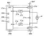
- FIG. 3 is a configuration diagram of the motor drive circuit according to the first embodiment.
- the brake control unit BCU includes a CPU 21a, a high-side motor drive FET 21b, a low-side motor drive FET 21c, a high-side voltage monitor 21d, a low-side voltage monitor 21e, a high-side low-pass filter 21f, a low-side low-pass filter 21g, and a free wheeling diode 21h.
- the CPU 21a calculates a target on-duty ratio of the motor M according to a program incorporated therein, and outputs a motor drive signal corresponding to the target on-duty ratio to the low-side motor drive FET 21c.
- the target on-duty ratio is an on-duty ratio of the motor M necessary for realizing the target wheel cylinder hydraulic pressure in the brake control.
- the CPU 21a always turns on the high-side motor drive FET 21b when the system is operating normally, and turns off the high-side motor drive FET 21b at the time of failure or when the system is shut down to prevent malfunction of the motor. To prevent.
- the high side motor drive FET 21b is provided between the in-vehicle battery BAT and the high side terminal of the motor M and functions as a fail-safe relay.
- the low-side motor drive FET 21c is provided between the ground GND and the low-side terminal of the motor M, and connects the ground GND and the low-side terminal of the motor M when the motor drive signal is input (motor drive signal ON) When the drive signal is not input (motor drive signal is off), the connection between the ground GND and the low side terminal of the motor M is cut off.
- the high side voltage monitor 21d detects the voltage of the high side terminal of the motor M, and takes the detected value into the CPU 21a.
- the low-side voltage monitor 21e detects the voltage at the low-side terminal of the motor M and takes the detected value into the CPU 21a.
- the high-side low-pass filter 21f removes noise from the signal input to the high-side voltage monitor 21d.
- the low-side low-pass filter 21g removes noise from the signal input to the low-side voltage monitor 21e.
- the freewheeling diode 21h is provided in parallel with the motor M, rectifies the current when the low-side motor drive FET 21c is off, smoothes the motor rotation speed in PWM drive, and absorbs the surge generated when the low-side motor drive FET 21c is off. Reduce the load on the low-side motor drive FET 21c.
- the CPU 21a of the brake control unit BCU performs a motor lock abnormality determination process as described below as a self-diagnosis of the motor M in order to determine whether or not the motor M has a lock abnormality.
- the CPU 21a includes a drive command unit 22a, a terminal voltage detection unit 22b, and a motor lock abnormality determination unit 22c as a configuration for performing the motor lock abnormality determination process.
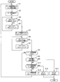
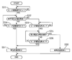
- FIG. 4 is a flowchart illustrating the flow of the motor lock abnormality determination process according to the first embodiment.
- step S1 the motor lock abnormality determination unit 22c sets a set on-time based on the number of times of motor driving, and proceeds to step S2.
- the set on-time is set to the same minimum time (for example, 1 msec) when the number of times of motor driving is 1 or 2 times, and is increased as the number of times of motor driving is increased (for example, when the number of times of motor driving is 3 or more) (for example, 3m 2msec, 4m 3msec, 5m 20msec).
- the number of times of motor driving indicates the number of times of driving when the on / off driving including the motor driving signal ON and the motor driving signal OFF is defined as one time.
- the drive command unit 22a outputs a motor drive signal (motor drive signal on), and proceeds to step S3.
- the target on-duty ratio is 100%.
- step S3 the motor lock abnormality determination unit 22c determines whether the counter T1 is less than the set on-time set in step S1. If YES, the process proceeds to step S4. If NO, the process proceeds to step S5. In step S4, the motor lock abnormality determination unit 22c counts up the counter T1, and returns to step S3. In step S5, the drive command unit 22a stops outputting the motor drive signal (motor drive signal off), the motor lock abnormality determination unit 22c clears the counter T1, and the process proceeds to step S6.
- Steps S2 and S5 are drive command steps for driving the motor M so that the peak of the motor rotation speed increases as the on / off drive is repeated after the on / off drive of the motor M is repeated a plurality of times.
- step S6 the motor lock abnormality determination unit 22c determines whether the counter T2 is less than the predetermined off time. If YES, the process proceeds to step S7. If NO, the process proceeds to step S8.
- the predetermined off time is shorter than the time from when the normal motor M having no lock abnormality under normal temperature environment starts inertial rotation when the first on / off driving is turned off until the motor rotation speed becomes zero (for example, , 5msec). The predetermined off time is obtained in advance by experiments or the like.
- step S7 the motor lock abnormality determination unit 22c counts up the counter T2, and returns to step S6.
- step S8 it is determined whether the motor drive count is greater than zero. If YES, the process proceeds to step S9. If NO, the process returns to step S1.
- step S9 the terminal voltage detection unit 22b calculates the terminal voltage from the absolute value of the difference between the high-side terminal voltage and the low-side terminal voltage of the motor M, and the motor lock abnormality determination unit 22c performs a lock check on the terminal voltage. It is determined whether the voltage threshold is exceeded. If YES, the process proceeds to step S10. If NO, the process proceeds to step S11.
- Step S9 is a terminal voltage detection step of detecting the terminal voltage of the motor M at the time of on / off driving by the drive command step.
- step S10 the motor lock abnormality determination unit 22c determines that “no lock abnormality” and ends the motor lock abnormality determination process.
- step S11 the motor lock abnormality determination unit 22c determines whether or not the motor drive count is equal to or greater than the upper limit count (predetermined count). If YES, the process proceeds to step S12. If NO, the process proceeds to step S13. There are a plurality of upper limit times, and the number of times that a lock abnormality can be reliably determined regardless of variations such as individual differences of the motor M.
- step S12 the motor lock abnormality determination unit 22c determines that “lock abnormality is present” and ends the motor lock abnormality determination process.
- Steps S10 and S12 are motor lock abnormality determination steps for determining whether there is a lock abnormality based on the characteristics of the terminal voltage when the on / off drive is off detected in the terminal voltage detection step.
- step S13 the motor drive count is counted up and the process returns to step S1.
- the CPU 21a determines that there is a lock abnormality by the motor lock abnormality determination process
- the CPU 21a stores a history indicating the lock abnormality in a nonvolatile memory or the like, turns on a warning lamp, and prohibits brake control.
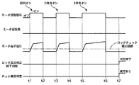
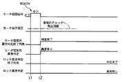
- FIG. 5 is a time chart illustrating an operation when the motor lock is not generated in the motor lock abnormality determination process of the first embodiment.
- the upper limit of the number of motor driving times is three.
- motor lock abnormality determination processing is started.
- the motor M is turned on (driven with an on-duty ratio of 100%), and the first on / off drive is started. Since the motor M is normal (not locked), the motor rotation speed increases in accordance with the increase of the terminal voltage during the period from the time t1 to t2.
- the motor M is turned off (driving stopped).
- the motor M Since the motor M starts inertial rotation, a counter electromotive force is generated. In the period from time t2 to t3, the terminal voltage also decreases as the motor rotation speed decreases. At time t3, a predetermined off time elapses from time t2, but when the first on / off drive is off, the motor M is turned on and the second on / off drive is started because it is not determined whether there is a motor lock abnormality. During the period from time t3 to t4, the motor rotation speed increases as the terminal voltage increases. At time t4, since the set on-time has elapsed from time t3, the motor M is turned off.
- the peak of the motor rotation speed (reached rotation speed) is higher than the peak at the time of the first on / off drive at time t2.
- the terminal voltage also decreases as the motor rotation speed decreases.
- the presence / absence of motor lock abnormality is determined by comparing the terminal voltage with the lock check voltage threshold value.
- the terminal voltage is higher than the lock check voltage threshold value, it is determined that there is no motor lock abnormality, and the motor lock abnormality determination process ends.
- FIG. 6 is a time chart illustrating an operation when the motor lock is generated in the motor lock abnormality determination process of the first embodiment.
- the upper limit of the number of motor driving times is three.
- motor lock abnormality determination processing is started.
- the motor M is turned on and the first on / off drive is started. Since the motor M is locked, the terminal voltage increases while the motor rotation speed remains zero during the period from time t1 to t2.
- the motor M is turned off. Since the motor M is locked, the terminal voltage becomes zero. In the period from time t2 to t3, both the terminal voltage and the motor speed remain zero.
- a predetermined off time elapses from time t2, but when the first on / off drive is off, the motor M is turned on and the second on / off drive is started because it is not determined whether there is a motor lock abnormality.
- the terminal voltage increases, but the motor rotation speed remains zero.
- the motor M is turned off. The terminal voltage becomes zero.
- both the terminal voltage and the motor rotation number remain zero.
- the presence / absence of motor lock abnormality is determined by comparing the terminal voltage with the lock check voltage threshold value.
- the motor M is turned on and the third on / off drive is started.
- the terminal voltage increases, but the motor rotation speed remains zero.
- the motor M is turned off. The terminal voltage becomes zero. In the period from time t6 to t7, both the terminal voltage and the motor speed remain zero.
- the on / off drive is repeated a plurality of times so that the motor speed at the time of off does not become zero, and the peak of the motor speed becomes higher as the time of on later.
- the motor M is driven so that
- the second on / off drive on duty ratio 100%
- the second on / off drive in order to increase the motor rotational speed to the rotational speed at which it is possible to determine whether there is a lock abnormality, it is necessary to take a sufficiently long on time.
- the motor lock abnormality determination process of the first embodiment since the next on / off drive is started before inertial rotation stops, the on time of one on / off drive is shorter than the conventional one, but at the later on time. The peak of the motor rotation speed can be increased. At this time, the motor drive sound is intermittently generated. However, even if the on-duty ratio is 100%, the motor drive sound becomes smaller as the on-time is shorter. In addition, the presence or absence of a lock abnormality is determined while gradually increasing the peak of the motor rotation speed each time the on / off drive is performed.
- the motor rotation speed can be increased to the rotation speed at which it is possible to determine whether there is a lock abnormality or not with the minimum necessary number of times of motor driving. Therefore, in the motor lock abnormality determination process of the first embodiment, it is possible to reduce the motor driving sound during the self-diagnosis of the motor M regardless of the situation.
- the brake fluid becomes highly viscous in a low temperature environment, and the rotational resistance of the motor M increases compared to that in the normal temperature environment. Therefore, even if the motor M is not locked, the motor rotation speed is zero during the predetermined off time. Therefore, there is a possibility that the peak of the motor rotation speed does not increase. Therefore, in the motor lock abnormality determination process of the first embodiment, the on-time is gradually lengthened as the number of motor driving increases. As a result, it is possible to reliably determine whether there is a lock abnormality regardless of the situation.
- the brake device includes a hydraulic unit HU having a pump P that generates a brake hydraulic pressure with respect to a brake operation unit BU provided on the wheels FL to RR, and a motor M that rotationally drives the pump P.
- a drive command unit 22a that drives the motor M so that the motor rotation speed at the time of OFF does not become zero and the peak of the motor rotation speed increases at the later ON time by repeating the on / off drive multiple times.
- a terminal voltage detection unit 22b that detects the terminal voltage of the motor M during on / off driving by the command unit 22a, and whether there is a lock abnormality in the motor M based on the characteristics of the terminal voltage when the on / off driving is detected detected by the terminal voltage detection unit 22b
- a brake control unit BCU having a motor lock abnormality determination unit 22c for determining Therefore, it is possible to reduce the motor driving noise during the self-diagnosis of the motor with the minimum number of on / off driving times regardless of the situation.
- the motor lock abnormality determination unit 22c determines whether there is a lock abnormality based on whether or not the terminal voltage when the on / off drive is off detected by the terminal voltage detection unit 22b is larger than a predetermined threshold.
- the motor lock abnormality determination unit 22c starts determining whether there is a lock abnormality when the second on / off drive is turned off by the drive command unit 22a. Since the peak of the motor rotation speed is low at the first on / off driving, there is a possibility that a terminal voltage capable of determining whether there is a lock abnormality does not occur. Therefore, the determination accuracy can be improved by starting the determination of the presence or absence of lock abnormality from the second on / off drive.
- the motor lock abnormality determination unit 22c determines that there is a lock abnormality when it is not determined that there is no lock abnormality even after repeating the ON / OFF drive by the drive command unit 22a the upper limit number of times. Therefore, it is possible to suppress an unnecessary increase in the number of on / off driving operations, and to shorten the determination time for the presence or absence of lock abnormality.
- the brake control method is a brake control method having a pump P that generates a brake fluid pressure for a brake operation unit BU provided on the wheels FL to RR and is driven to rotate by a motor M.
- the drive command step (S2, S5) for driving the motor M so that the motor speed at the time of OFF does not become zero and the peak of the motor speed increases at the later time of ON
- the drive command A terminal voltage detection step (S9) for detecting the terminal voltage of the motor M at the time of on / off driving by the step, and a motor for determining whether there is a lock abnormality based on the characteristics of the terminal voltage at the off time of the on / off driving detected at the terminal voltage detection step
- the motor lock abnormality determination step determines whether or not the terminal voltage when the on / off drive is off detected in the terminal voltage detection step is greater than a predetermined threshold. Therefore, the presence or absence of motor lock abnormality can be determined based on the absolute value of the terminal voltage of the motor M.
- determination of whether or not there is a lock abnormality is started when the second on / off drive is turned off in the drive command step.
- the determination accuracy can be improved by starting the determination of the presence or absence of lock abnormality from the second on / off drive.
- the motor lock abnormality determination step if it is not determined that there is no lock abnormality even after ON / OFF drive in the drive command step is repeated the upper limit number of times, it is determined that there is a lock abnormality. Therefore, it is possible to suppress an unnecessary increase in the number of on / off driving operations, and to shorten the determination time for the presence or absence of lock abnormality.
- the motor abnormality determination method repeats the on / off drive multiple times so that the motor M does not become zero at the time of off, and the peak of the motor speed increases at the later on time.
- Drive command step (S2, S5) to drive terminal voltage detection step (S9) to detect the terminal voltage of motor M during on / off drive by drive command step, and on / off drive off detected in terminal voltage detection step
- FIG. 7 is a flowchart illustrating the flow of the motor lock abnormality determination process according to the second embodiment. The same processing steps as those in FIG. 4 are denoted by the same step numbers and description thereof is omitted.
- step S5 output of the motor drive signal is stopped in the drive command unit 22a, the counter T1 is cleared in the motor lock abnormality determination unit 22c, and at the same time, the terminal voltage detection unit 22b The terminal voltage is calculated from the absolute value of the difference from the voltage at the low side terminal, and the process proceeds to step S6.
- step S21 the terminal voltage detector 22b calculates the terminal voltage from the absolute value of the difference between the voltage on the high side terminal and the voltage on the low side terminal of the motor M, and the obtained terminal voltage and the terminal voltage obtained in step S5.
- the decrease gradient (gradient) of the terminal voltage is calculated from the above, and the motor lock abnormality determination unit 22c determines whether the gradient of the terminal voltage is equal to or greater than the gradient threshold. If YES, the process proceeds to step S10. If NO, the process proceeds to step S11.
- Step S9 is a terminal voltage detection step.
- the operation of the motor lock abnormality determination process of the second embodiment is the same as that of the first embodiment shown in FIGS.
- the motor lock abnormality determination unit 22c determines whether there is a lock abnormality based on whether the change rate of the terminal voltage when the on / off drive is off detected by the terminal voltage detection unit 22b is greater than a predetermined change rate. . Therefore, the presence or absence of motor lock abnormality can be determined based on the rate of change of the terminal voltage of the motor M.
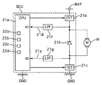
- FIG. 8 is a configuration diagram of a motor drive circuit according to the third embodiment.
- the CPU 21a of the brake control unit BCU performs a motor electrical abnormality determination process simultaneously with the start of the motor lock abnormality determination process in order to determine the presence or absence of an electrical abnormality of the motor M.
- the CPU 21a includes a motor electrical abnormality determination unit 22d.
- the motor lock abnormality determination process of the third embodiment is almost the same as that of the first embodiment shown in FIG. 4, but the predetermined off time in step S6 is different from that of the first embodiment.
- the predetermined off-time is set to the same time as the first embodiment (for example, 5 msec) when the motor driving frequency is 1 or more, and when the motor driving frequency is 0, the predetermined off time is longer than the time of 1 or more (for example, 15 msec).
- the motor lock abnormality determination process is stopped and the presence / absence of a lock abnormality is not determined.
- FIG. 9 is a flowchart illustrating the flow of the motor electrical abnormality determination process according to the third embodiment.
- the motor electrical abnormality determination process starts simultaneously with the motor lock abnormality determination process.
- step S31 the motor electrical abnormality determination unit 22d determines whether the motor drive signal is turned on. If YES, the process proceeds to step S32. If NO, step S31 is repeated.
- step S32 the terminal voltage detector 22b calculates the terminal voltage from the absolute value of the difference between the high-side terminal voltage and the low-side terminal voltage of the motor M, and the motor electrical abnormality determination unit 22d It is judged whether it is more than the static check voltage threshold value.
- step S33 the motor electrical abnormality determination unit 22d determines whether the motor drive signal is turned on. If yes, then continue with step S35, otherwise repeat step S33.
- step S34 the motor electrical abnormality determination unit 22d determines whether the motor drive signal is turned off. If YES, the process proceeds to step S37, and if NO, the process returns to step S32.
- step S35 the terminal voltage detection unit 22b calculates the terminal voltage from the absolute value of the difference between the high-side terminal voltage and the low-side terminal voltage of the motor M, and the motor electrical abnormality determination unit 22d It is judged whether it is more than the static check voltage threshold value.
- step S36 the motor electrical abnormality determination unit 22d determines whether the motor drive signal is turned off. If YES, the process proceeds to step S37, and if NO, the process returns to step S35. In step S37, the motor electrical abnormality determination unit 22d determines that “there is an electrical abnormality” and ends the motor electrical abnormality determination process. In step S38, the motor electrical abnormality determination unit 22d determines “no electrical abnormality” and ends the motor electrical abnormality determination process.
- FIG. 10 is a time chart illustrating an operation when no motor electrical abnormality has occurred in the motor lock abnormality determination process and the motor electrical abnormality determination process of the third embodiment. It is assumed that no motor lock has occurred. At time t1, the motor M is turned on and the first on / off drive is started. Since there is no electrical abnormality in the motor M, the terminal voltage rises during the period from time t1 to t2. Further, since the motor M is not locked, the motor rotation speed increases as the terminal voltage increases. From time t1 to t2, since the terminal voltage has exceeded the electrical check voltage threshold, the motor lock abnormality determination process is continued.
- the motor M is turned off. In the period from time t2 to t3, the terminal voltage also decreases as the motor rotation speed decreases. At time t3, since a predetermined off time has elapsed from time t2, the motor M is turned on and the second on / off driving is started. In the period from time t3 to t4, since the terminal voltage has exceeded the electrical check voltage threshold, it is determined that there is no electrical abnormality, and the motor electrical abnormality determination process ends. The motor lock determination process is continued by determining that there is no electrical abnormality. At time t4, since the set on-time has elapsed from time t3, the motor M is turned off.
- the terminal voltage also decreases as the motor rotation speed decreases.
- the presence / absence of motor lock abnormality is determined by comparing the terminal voltage with the lock check voltage threshold value.
- the motor M is turned on and the third on / off drive is started.
- the motor M is turned off.
- FIG. 11 is a time chart illustrating an operation when a motor electrical abnormality has occurred in the motor lock abnormality determination process and the motor electrical abnormality determination process of the third embodiment.
- the motor M is turned on and the first on / off drive is started. Since an electrical abnormality has occurred in the motor M, the terminal voltage remains zero during the period from time t1 to time t2.
- the motor M is turned off. Since the terminal voltage has not reached the electrical check voltage threshold at the first ON, it is determined that there is an electrical abnormality, and the motor electrical abnormality determination process is terminated. When it is determined that there is an electrical abnormality, the motor lock determination process is also terminated.
- the presence / absence of a motor electrical abnormality is determined based on the terminal voltage at the time of the first on / off drive that does not determine the presence / absence of a lock abnormality. If a motor electrical abnormality has occurred, no terminal voltage will be generated after the motor is turned off. For this reason, by determining the presence / absence of the motor electrical abnormality before the determination of the presence / absence of the lock abnormality, it is possible to suppress erroneously determining the occurrence of the motor electrical abnormality as the lock abnormality.
- the brake control unit BCU includes a motor electrical abnormality determination unit 22d that determines the presence or absence of an electrical abnormality of the motor M based on the terminal voltage when the first on / off drive is turned on by the drive command unit 22a.
- the first on / off drive that does not determine whether there is a lock abnormality can be used to determine whether there is an electrical abnormality.
- erroneous determination of whether there is a lock abnormality can be suppressed.
- the motor electrical abnormality determination unit 22d determines that there is an electrical abnormality
- the motor lock abnormality determination unit 22c interrupts the determination of whether there is a lock abnormality. Accordingly, it is possible to suppress erroneous determination of occurrence of motor electrical abnormality as lock abnormality.
- the embodiment of the present invention has been described above, the specific configuration of the present invention is not limited to the configuration shown in the embodiment, and the present invention can be changed even if there is a design change or the like without departing from the gist of the invention. Included in the invention. In addition, any combination or omission of each constituent element described in the claims and the specification is possible within a range where at least a part of the above-described problems can be solved or a range where at least a part of the effect is achieved. It is.
- the on-duty ratio may be less than 100% as long as the motor can be driven so that the peak of the motor rotation speed increases as the on / off drive is repeated when the on / off drive is repeated a plurality of times.
- the number of times of motor driving may be plural.
- the set on time of the motor may be constant regardless of the number of times the motor is driven. Further, the temperature of the outside air temperature and the brake fluid may be measured, and the set on-time may be made longer as the later on / off drive only when the outside air temperature and the temperature of the brake fluid are below the low temperature determination threshold.
- the determination of whether or not there is a lock abnormality and the determination of the presence or absence of an electrical abnormality may be performed in parallel.
- a hydraulic unit including a pump that generates a brake hydraulic pressure with respect to a braking force generation unit provided on a wheel, and a motor that rotationally drives the pump, and an on / off drive. Repeated multiple times so that the motor rotation number at the time of off does not become zero, and the drive command unit drives the motor so that the peak of the motor rotation number becomes higher at the later on time, and the drive command unit A terminal voltage detector that detects a terminal voltage of the motor at the time of the on / off drive, and determines whether or not the motor is locked based on characteristics of the terminal voltage at the time of the on / off drive being off detected by the terminal voltage detector.
- the motor lock abnormality determination unit determines whether or not there is a lock abnormality based on whether or not the terminal voltage when the on / off drive is off detected by the terminal voltage detection unit is greater than a predetermined threshold. Determine.
- the motor lock abnormality determination unit starts determining whether there is a lock abnormality when the second on / off drive is turned off by the drive command unit.
- the motor lock abnormality determination unit does not determine that there is no lock abnormality even after repeating the on / off drive by the drive command unit a predetermined number of times, there is a lock abnormality. Is determined.
- control unit determines whether or not the motor is abnormal based on a terminal voltage when the first on / off drive is turned on by the drive command unit.
- An abnormality determination unit was provided.
- the motor lock abnormality determination unit interrupts the determination of the presence or absence of the lock abnormality when the motor electrical abnormality determination unit determines that there is an electrical abnormality.
- the motor electrical abnormality determination unit determines the presence or absence of an electrical abnormality even when the second on / off drive is turned on by the drive command unit.
- the motor lock abnormality determination unit has a rate of change of the terminal voltage detected when the on-off drive is detected, which is detected by the terminal voltage detection unit, lower than a predetermined rate of change. The presence / absence of lock abnormality is determined based on whether or not it is large.
- the brake control method is a brake control method including a pump that generates a brake fluid pressure with respect to a braking force generation unit provided on a wheel and is driven to rotate by a motor, A drive command step for driving the motor to repeat the on / off drive a plurality of times so that the motor rotational speed at the time of off does not become zero and so that the peak of the motor rotational speed becomes higher at the later on time;
- the terminal voltage detection step for detecting the terminal voltage of the motor at the time of the on / off drive by the command step, and the presence / absence of the lock abnormality is determined based on the characteristics of the terminal voltage at the time of the off time of the on / off drive detected at the terminal voltage detection step.
- a motor lock abnormality determining step is a brake control method including a pump that generates a brake fluid pressure with respect to a braking force generation unit provided on a wheel and is driven to rotate by a motor,
- a drive command step for driving the motor to repeat the on / off drive a pluralit
- the motor lock abnormality determination step it is determined whether or not there is a lock abnormality based on whether or not the terminal voltage when the on / off drive is off detected in the terminal voltage detection step is greater than a predetermined threshold. To do.
- determination of whether or not there is a lock abnormality is started when the second on / off drive is turned off by the drive command step.
- in the motor lock abnormality determination step if it is not determined that there is no lock abnormality even if the on / off drive in the drive command step is repeated a predetermined number of times, a lock abnormality is present. judge.
- the method includes a motor electrical abnormality determination step for determining the presence or absence of an electrical abnormality of the motor based on a terminal voltage when the first on / off drive is turned on by the drive command step. It was.
- the motor lock abnormality determination step when it is determined in the motor electrical abnormality determination step that there is an electrical abnormality, the determination of the presence or absence of the lock abnormality is interrupted.
- the presence / absence of an electrical abnormality is determined even when the second on / off drive is turned on by the drive command step.
- the change rate of the terminal voltage when the on / off drive is off detected in the terminal voltage detection step is greater than a predetermined change rate.
- the presence / absence of lock abnormality is determined based on whether or not it is large.
- the motor lock abnormality determination method repeats the on / off drive a plurality of times so that the motor rotational speed at the time of off does not become zero, and the motor rotational speed is increased at the later on time.
- a drive command step for driving the motor to increase the peak a terminal voltage detection step for detecting a terminal voltage of the motor during the on / off drive by the drive command step, and the terminal voltage detection step
- the motor lock abnormality determination step it is determined whether or not there is a lock abnormality based on whether or not the terminal voltage when the on / off drive is off detected in the terminal voltage detection step is greater than a predetermined threshold. To do.
- determination of whether or not there is a lock abnormality is started when the second on / off drive is turned off by the drive command step.
- in the motor lock abnormality determination step if it is not determined that there is no lock abnormality even after the on / off drive in the drive command step is repeated a predetermined number of times, there is a lock abnormality. Is determined.
- BCU brake control unit control unit
- BU brake operation unit braking force generation unit
- FL to RR wheels HU hydraulic unit
- M motor motor
- P oil pump pump
- 22a drive command unit 22b terminal voltage detection unit
- 22c Motor lock abnormality determination unit 22d
- Motor electrical abnormality determination unit 22d
Landscapes
- Engineering & Computer Science (AREA)
- Transportation (AREA)
- Mechanical Engineering (AREA)
- Physics & Mathematics (AREA)
- Fluid Mechanics (AREA)
- Regulating Braking Force (AREA)
- Valves And Accessory Devices For Braking Systems (AREA)
- Protection Of Generators And Motors (AREA)
Abstract
状況に依らずモータの自己診断時におけるモータ駆動音を低減できるブレーキ装置、ブレーキ制御方法およびモータロック異常判定方法を提供する。 ブレーキ制御方法は、オンオフ駆動を繰り返して、オフ時のモータ回転数がゼロにならないように、かつ、後のオン時ほどモータ回転数のピークが上昇するように、モータを駆動させる駆動指令ステップと、駆動指令ステップによるオンオフ駆動時におけるモータの端子電圧を検出する端子電圧検出ステップと、端子電圧検出ステップで検出されたオンオフ駆動のオフ時の端子電圧の特性に基づきモータのロック異常の有無を判定するモータロック異常判定ステップと、を備えた。
Description
本発明は、ブレーキ装置、ブレーキ制御方法およびモータロック異常判定方法に関する。
特許文献1には、ブレーキ装置において、ポンプを駆動させるモータのロック異常有無を判定する方法が開示されている。この従来技術では、モータを100%よりも低いオンデューティ比で一定時間駆動させ、その駆動終了時にロック異常無しと判定されない場合にのみ、モータをオンデューティ比100%で駆動させてロック異常有無を判定している。
しかしながら、上記従来技術にあっては、電源電圧低下時や低温環境下にはモータをオンデューティ比100%で一定時間駆動する必要があるため、モータ駆動音を低減できないという問題があった。
本発明の目的は、状況に依らずモータの自己診断時におけるモータ駆動音を低減できるブレーキ装置、ブレーキ制御方法およびモータロック異常判定方法を提供することにある。
本発明の目的は、状況に依らずモータの自己診断時におけるモータ駆動音を低減できるブレーキ装置、ブレーキ制御方法およびモータロック異常判定方法を提供することにある。
本発明の一つの実施形態に係るブレーキ装置は、オンオフ駆動を複数回繰り返して、オフ時のモータ回転数がゼロにならないように、かつ、後のオン時ほどモータ回転数のピークが高くなるようにモータを駆動させ、オンオフ駆動のオフ時の端子電圧の特性に基づきモータのロック異常有無を判定する。
よって、状況に依らずモータの自己診断時におけるモータ駆動音を低減できる。
〔実施形態1〕
図1は、実施形態1のブレーキ装置を適用した車両の制駆動系を示すシステム構成図である。
実施形態1のブレーキ装置は、エンジン車に適用されている。ブレーキ装置は、液圧による摩擦制動力を車両の各車輪各車輪(左前輪FL、右前輪FR、左後輪RL、右後輪RR)に付与する。各車輪FR~RRには、ブレーキ作動ユニットBUが設けられている。ブレーキ作動ユニットBUは、ホイルシリンダW/Cを含む制動力発生部である。ブレーキ作動ユニットBUは、例えばディスク式であり、キャリパ(油圧式ブレーキキャリパ)を有する。キャリパはブレーキディスクおよびブレーキパッドを備える。ブレーキディスクはタイヤと一体に回転するブレーキロータである。ブレーキパッドは、ブレーキディスクに対し所定のクリアランスを持って配置され、ホイルシリンダW/Cの液圧によって移動してブレーキディスクに接触する。ブレーキパッドがブレーキディスクに接触することにより摩擦制動力を発生する。
エンジンEは、自動変速機AT、ディファレンシャルギアDGを介して前輪左右FL,FRのフロントドライブシャフトFDS(FL),FDS(FR)とそれぞれ連結され、エンジンコントロールユニットECUからの指令に基づいて前輪左右FL,FRに駆動力を付与する。
エンジンコントロールユニットECUは、エンジン回転数センサ99からのエンジン回転数、吸入空気量、冷却水温、スロットルバルブの開度(スロットル開度)等の運転状態に基づき、エンジンEの燃料噴射量や点火時期を制御する。
ブレーキコントロールユニット(コントロールユニット)BCUは、マスタシリンダ液圧を検出する圧力センサ17からのマスタシリンダ液圧、各車輪FL~RRに設けられた各車輪速センサ100FL,100FR,100RL,100RRからの各車輪速、操舵角センサ101からのステアリングホイール102の操舵角、ヨーレイトセンサ103からのヨーレイト、前後Gセンサ104からの前後加速度、横Gセンサ105からの横加速度、ブレーキスイッチBSからブレーキペダルBPの操作信号等に基づき、液圧ユニットHUに指令を送る。液圧ユニットHUは、ブレーキコントロールユニットBCUからの指令に応じて各ブレーキ作動ユニットBUのホイルシリンダ液圧を増減または保持する。
図2は、実施形態1のブレーキ装置の液圧回路図である。
実施形態1のブレーキ装置は、2系統(プライマリP系統、セカンダリS系統)のブレーキ配管を有する。ブレーキ配管形式は、例えばX配管形式である。以下、P系統に対応する部位とS系統に対応する部位とを区別する場合は、それぞれの符号の末尾に添字P,Sを付す。P系統に対応する部位とS系統に対応する部位とを区別しない場合は、添字P,Sを省略する。また、左前輪FLに対応する部位、右前輪FRに対応する部位、左後輪RLに対応する部位、右後輪RRに対応する部位をそれぞれ区別する場合は、それぞれの符号の末尾に添字FL,FR,RL,RRを付す。左前輪FLに対応する部位、右前輪FRに対応する部位、左後輪RLに対応する部位、右後輪RRに対応する部位を区別しない場合は、添字FL,FR,RL,RRを省略する。ブレーキ装置は、ブレーキ配管を介して各ブレーキ作動ユニットにブレーキ液を供給することにより、各車輪FL~RRに制動力が付与される。
実施形態1のブレーキ装置は、2系統(プライマリP系統、セカンダリS系統)のブレーキ配管を有する。ブレーキ配管形式は、例えばX配管形式である。以下、P系統に対応する部位とS系統に対応する部位とを区別する場合は、それぞれの符号の末尾に添字P,Sを付す。P系統に対応する部位とS系統に対応する部位とを区別しない場合は、添字P,Sを省略する。また、左前輪FLに対応する部位、右前輪FRに対応する部位、左後輪RLに対応する部位、右後輪RRに対応する部位をそれぞれ区別する場合は、それぞれの符号の末尾に添字FL,FR,RL,RRを付す。左前輪FLに対応する部位、右前輪FRに対応する部位、左後輪RLに対応する部位、右後輪RRに対応する部位を区別しない場合は、添字FL,FR,RL,RRを省略する。ブレーキ装置は、ブレーキ配管を介して各ブレーキ作動ユニットにブレーキ液を供給することにより、各車輪FL~RRに制動力が付与される。
ブレーキペダルBPは、インプットロッドIRを介してマスタシリンダM/Cに接続されている。ブレーキペダルBPへ入力されたペダル踏力は、ブレーキブースタBBによって倍力される。ブレーキブースタBBは、エンジンが発生する吸気負圧を利用してブレーキ操作力を倍力する。マスタシリンダM/Cは、リザーバタンクRSVからブレーキ液を補給され、ブレーキペダルBPの操作に応じたマスタシリンダ液圧を発生する。マスタシリンダM/CとホイルシリンダW/Cは、液圧ユニットHUを介して接続されている。P系統には、左前輪FLのホイルシリンダW/C(FL)、右後輪RRのホイルシリンダW/C(RR)が接続されている。S系統には、左後輪RLのホイルシリンダW/C(RL)、右前輪FRのホイルシリンダW/C(FR)が接続されている。また、P系統、S系統には、オイルポンプ(ポンプ)PP,PSが設けられている。オイルポンプPP,PSは、1つのモータMにより駆動される。モータMは、回転式の電動機である。モータMは、例えばブラシモータである。オイルポンプPP,PSは、例えばプランジャポンプである。
液圧ユニットHUの内部には、マスタシリンダM/CとホイルシリンダW/Cとを接続する液路1および液路2が設けられている。液路2Sは、液路2RL,2FRに分岐し、液路2RLはホイルシリンダW/C(RL)と接続され、液路2FRはホイルシリンダW/C(FR)と接続される。液路2Pは、液路2FL,2RRに分岐し、液路2FLはホイルシリンダW/C(FL)と接続され、液路2RRはホイルシリンダW/C(RR)と接続される。液路1上には、常開型の電磁弁であるゲートアウト弁(以下G/V-OUT)3が設けられている。P系統の液路1PのG/V-OUT3Pよりもマスタシリンダ側の位置には、マスタシリンダ液圧を検出する圧力センサ17が設けられている。液路1上には、G/V-OUT3と並列に液路4が設けられている。液路4上には、チェックバルブ5が設けられている。チェックバルブ5は、マスタシリンダM/CからホイルシリンダW/Cへ向かうブレーキ液の流れを許容し、反対方向の流れを禁止する。液路2上には、各ホイルシリンダW/Cに対応する常開型の電磁弁であるソレノイドイン弁(以下Sol/V-IN)6が設けられている。液路2上には、Sol/V-IN6と並列に液路7が設けられている。液路7上には、チェックバルブ8が設けられている。チェックバルブ8は、ホイルシリンダW/CからマスタシリンダM/Cへ向かう方向へのブレーキ液の流れを許容し、反対方向の流れを禁止する。
液圧ユニットHUの内部には、マスタシリンダM/CとホイルシリンダW/Cとを接続する液路1および液路2が設けられている。液路2Sは、液路2RL,2FRに分岐し、液路2RLはホイルシリンダW/C(RL)と接続され、液路2FRはホイルシリンダW/C(FR)と接続される。液路2Pは、液路2FL,2RRに分岐し、液路2FLはホイルシリンダW/C(FL)と接続され、液路2RRはホイルシリンダW/C(RR)と接続される。液路1上には、常開型の電磁弁であるゲートアウト弁(以下G/V-OUT)3が設けられている。P系統の液路1PのG/V-OUT3Pよりもマスタシリンダ側の位置には、マスタシリンダ液圧を検出する圧力センサ17が設けられている。液路1上には、G/V-OUT3と並列に液路4が設けられている。液路4上には、チェックバルブ5が設けられている。チェックバルブ5は、マスタシリンダM/CからホイルシリンダW/Cへ向かうブレーキ液の流れを許容し、反対方向の流れを禁止する。液路2上には、各ホイルシリンダW/Cに対応する常開型の電磁弁であるソレノイドイン弁(以下Sol/V-IN)6が設けられている。液路2上には、Sol/V-IN6と並列に液路7が設けられている。液路7上には、チェックバルブ8が設けられている。チェックバルブ8は、ホイルシリンダW/CからマスタシリンダM/Cへ向かう方向へのブレーキ液の流れを許容し、反対方向の流れを禁止する。
オイルポンプPの吐出側と液路2とは、液路9により接続される。液路9上には、吐出バルブ10が設けられている。吐出バルブ10は、オイルポンプPから液路2へ向かう方向へのブレーキ液の流れを許容し、反対方向の流れを禁止する。液路1のG/V-OUT3よりもマスタシリンダ側の位置と、オイルポンプPの吸入側とは、液路11と液路12により接続される。液路11と液路12との間には、調圧リザーバ13が設けられている。液路2のSol/V-IN6よりもホイルシリンダ側の位置と調圧リザーバ13とは液路14により接続される。液路14Sは液路14RL,14FRに分岐し、液路14Pは液路14FL,14RRに分岐し、対応するホイルシリンダW/Cと接続される。液路14上には、常閉型の電磁弁であるソレノイドアウト弁(以下、Sol/V-OUT)15が設けられている。調圧リザーバ13は、リザーバピストン13aとリザーバスプリング13bおよびチェックバルブ16を備える。リザーバピストン13aは、リザーバ内部を上下にストローク可能に設けられている。リザーバピストン13aは、リザーバ内部に流入したブレーキ液量が増加するに従い下降し、ブレーキ液量が減少するに従い上昇する。リザーバスプリング13bは、リザーバピストン13aを上昇する方向に付勢する。チェックバルブ16は、ボール弁16aおよび弁座16bを有する。ボール弁16aは、リザーバピストン13aと一体に設けられ、リザーバピストン13aのストロークに応じて上下動する。ボール弁16aは、図外のバルブスプリングにより下降方向に付勢されている。バルブスプリングの弾性力は、リザーバスプリング13bの弾性力よりも弱く設定されている。弁座16bは、ボール弁16aの下降時にボール弁16aと当接する。
リザーバピストン13aは、液路14からブレーキ液が流入した場合にはリザーバスプリング13bの付勢力に抗して下降する。これにより、リザーバ内部にブレーキ液が流入する。リザーバ内部に流入したブレーキ液は、液路12を経由してオイルポンプPの吸入側へ供給される。このとき、リザーバピストン13aの下降に伴ってボール弁16aも下降し、バルブスプリングの付勢力によって弁座16bに着座(当接)する。これにより、チェックバルブ16は閉弁状態となる。よって、オイルポンプPの作動時、オイルポンプPの吸引能力よりも多くのブレーキ液が調圧リザーバ13に流入すれば、チェックバルブ16は閉弁状態となってマスタシリンダ側から調圧リザーバ13へのブレーキ液の流入は停止する。一方、オイルポンプPの作動時に調圧リザーバ13へ流入するブレーキ液がオイルポンプPの吸引能力よりも少ない場合は、液路12内の圧力が低下することでリザーバピストン13aが上昇する。このとき、リザーバピストン13aの上昇に伴ってボール弁16aも上昇し弁座16bから離間する。これにより、チェックバルブ16は開弁状態となる。よって、マスタシリンダ側とオイルポンプPの吸入側とが連通されるため、マスタシリンダ側から調圧リザーバ13へブレーキ液が流入する。なお、チェックバルブ16は、ドライバがブレーキペダルBPを踏み込んでいる場合等、液路11内の圧力が所定圧を超える高圧となった場合には閉弁状態となる。これにより、マスタシリンダ側から調圧リザーバ13へのブレーキ液の流動は起こらず、オイルポンプPの吸入側に高圧が作用するのを防止できる。
ブレーキコントロールユニットBCUは、ブレーキ制御として、アンチロックブレーキ(ABS)制御を実施する。ABS制御は、ドライバのブレーキ操作時に車輪がロック傾向になったことを検知すると、当該車輪に対し、ロックを防止しつつ最大の制動力を発生させるためにホイルシリンダ液圧の減圧、保持、増圧を繰り返す制御である。ABS減圧制御時には、図2の状態(各バルブがオフの状態)からSol/V-IN6を閉じると共にSol/V-OUT15を開き、ホイルシリンダW/Cのブレーキ液を調圧リザーバ13に逃がすことでホイルシリンダ液圧を低下させる。ABS保持制御では、Sol/V-IN6およびSol/V-OUT15を共に閉じることでホイルシリンダ液圧を保持する。ABS増圧制御では、Sol/V-IN6を開弁方向へ制御すると共にSol/V-OUT15を閉じ、マスタシリンダM/Cからブレーキ液をホイルシリンダW/Cへ供給することでホイルシリンダ液圧を増加させる。
また、ブレーキコントロールユニットBCUは、ブレーキ制御として、各バルブおよびオイルポンプPを作動させることにより、車両挙動安定制御、ブレーキアシスト制御、先行車追従制御等の自動ブレーキ制御を実施可能である。車両挙動安定制御は、車両旋回時にオーバーステア傾向やアンダーステア傾向が強くなったことを検出すると、所定の制御対象輪のホイルシリンダ液圧を制御して車両挙動安定化を図る制御である。ブレーキアシスト制御は、ドライバのブレーキ操作時に実際にマスタシリンダM/Cで発生する圧力よりも高い圧力をホイルシリンダW/Cで発生させる制御である。先行者追従制御は、オートクルーズコントロールにより先行車との相対関係に応じて自動的に制動力を発生させる制御である。
また、ブレーキコントロールユニットBCUは、ブレーキ制御として、各バルブおよびオイルポンプPを作動させることにより、車両挙動安定制御、ブレーキアシスト制御、先行車追従制御等の自動ブレーキ制御を実施可能である。車両挙動安定制御は、車両旋回時にオーバーステア傾向やアンダーステア傾向が強くなったことを検出すると、所定の制御対象輪のホイルシリンダ液圧を制御して車両挙動安定化を図る制御である。ブレーキアシスト制御は、ドライバのブレーキ操作時に実際にマスタシリンダM/Cで発生する圧力よりも高い圧力をホイルシリンダW/Cで発生させる制御である。先行者追従制御は、オートクルーズコントロールにより先行車との相対関係に応じて自動的に制動力を発生させる制御である。
図3は、実施形態1のモータ駆動回路の構成図である。
ブレーキコントロールユニットBCUは、CPU21a、ハイサイドモータ駆動FET21b、ローサイドモータ駆動FET21c、ハイサイド電圧モニタ21d、ローサイド電圧モニタ21e、ハイサイドローパスフィルタ21f、ローサイドローパスフィルタ21gおよび還流ダイオード21hを有する。CPU21aは、内部に組み込まれたプログラムに従い、モータMの目標オンデューティ比を演算し、目標オンデューティ比に応じたモータ駆動信号をローサイドモータ駆動FET21cに出力する。目標オンデューティ比は、ブレーキ制御において目標ホイルシリンダ液圧を実現するために必要なモータMのオンデューティ比である。また、CPU21aは、システムが正常に動作しているときは常時ハイサイドモータ駆動FET21bをオン状態とし、故障時やシステム遮断時はハイサイドモータ駆動FET21bをオフすることで故障によるモータ誤作動等を防止する。ハイサイドモータ駆動FET21bは、車載バッテリBATとモータMのハイサイド端子との間に設けられ、フェールセーフリレーとして機能する。ローサイドモータ駆動FET21cは、グランドGNDとモータMのローサイド端子との間に設けられ、モータ駆動信号の入力時(モータ駆動信号オン)にはグランドGNDとモータMのローサイド端子とを接続する一方、モータ駆動信号の非入力時(モータ駆動信号オフ)にはグランドGNDとモータMのローサイド端子との接続を遮断する。ハイサイド電圧モニタ21dは、モータMのハイサイド端子の電圧を検出し、検出値をCPU21a内部に取り込む。ローサイド電圧モニタ21eは、モータMのローサイド端子の電圧を検出し、検出値をCPU21a内部に取り込む。ハイサイドローパスフィルタ21fは、ハイサイド電圧モニタ21dに入力される信号からノイズを除去する。ローサイドローパスフィルタ21gは、ローサイド電圧モニタ21eに入力される信号からノイズを除去する。還流ダイオード21hは、モータMと並列に設けられ、ローサイドモータ駆動FET21cのオフ時の電流を整流し、PWM駆動におけるモータ回転数の平滑化、およびローサイドモータ駆動FET21cのオフ時に生じるサージを吸収してローサイドモータ駆動FET21cの負荷を軽減する。
ブレーキコントロールユニットBCUは、CPU21a、ハイサイドモータ駆動FET21b、ローサイドモータ駆動FET21c、ハイサイド電圧モニタ21d、ローサイド電圧モニタ21e、ハイサイドローパスフィルタ21f、ローサイドローパスフィルタ21gおよび還流ダイオード21hを有する。CPU21aは、内部に組み込まれたプログラムに従い、モータMの目標オンデューティ比を演算し、目標オンデューティ比に応じたモータ駆動信号をローサイドモータ駆動FET21cに出力する。目標オンデューティ比は、ブレーキ制御において目標ホイルシリンダ液圧を実現するために必要なモータMのオンデューティ比である。また、CPU21aは、システムが正常に動作しているときは常時ハイサイドモータ駆動FET21bをオン状態とし、故障時やシステム遮断時はハイサイドモータ駆動FET21bをオフすることで故障によるモータ誤作動等を防止する。ハイサイドモータ駆動FET21bは、車載バッテリBATとモータMのハイサイド端子との間に設けられ、フェールセーフリレーとして機能する。ローサイドモータ駆動FET21cは、グランドGNDとモータMのローサイド端子との間に設けられ、モータ駆動信号の入力時(モータ駆動信号オン)にはグランドGNDとモータMのローサイド端子とを接続する一方、モータ駆動信号の非入力時(モータ駆動信号オフ)にはグランドGNDとモータMのローサイド端子との接続を遮断する。ハイサイド電圧モニタ21dは、モータMのハイサイド端子の電圧を検出し、検出値をCPU21a内部に取り込む。ローサイド電圧モニタ21eは、モータMのローサイド端子の電圧を検出し、検出値をCPU21a内部に取り込む。ハイサイドローパスフィルタ21fは、ハイサイド電圧モニタ21dに入力される信号からノイズを除去する。ローサイドローパスフィルタ21gは、ローサイド電圧モニタ21eに入力される信号からノイズを除去する。還流ダイオード21hは、モータMと並列に設けられ、ローサイドモータ駆動FET21cのオフ時の電流を整流し、PWM駆動におけるモータ回転数の平滑化、およびローサイドモータ駆動FET21cのオフ時に生じるサージを吸収してローサイドモータ駆動FET21cの負荷を軽減する。
[モータロック異常判定処理]
ブレーキコントロールユニットBCUのCPU21aは、モータMのロック異常有無を判定するために、モータMの自己診断として、以下に示すようなモータロック異常判定処理を実施する。CPU21aは、モータロック異常判定処理を実施するための構成として、駆動指令部22a、端子電圧検出部22bおよびモータロック異常判定部22cを有する。
図4は、実施形態1のモータロック異常判定処理の流れを示すフローチャートである。
ステップS1では、モータロック異常判定部22cにおいて、モータ駆動回数より、設定オン時間を設定し、ステップS2へ進む。設定オン時間は、モータ駆動回数が1回および2回の場合は、同じ最短時間(例えば、1msec)とし、モータ駆動回数が3回以上の場合は、モータ駆動回数が多くなるほど長くする(例えば、3回では2msec、4回では3msec、5回では20msec)。ここで、モータ駆動回数とは、モータ駆動信号オンとモータ駆動信号オフを合わせたオンオフ駆動を1回としたときの駆動回数を示す。
ステップS2では、駆動指令部22aにおいて、モータ駆動信号を出力(モータ駆動信号オン)し、ステップS3へ進む。目標オンデューティ比は100%とする。
ステップS3では、モータロック異常判定部22cにおいて、カウンタT1がステップS1で設定した設定オン時間未満であるかを判定する。YESの場合はステップS4へ進み、NOの場合はステップS5へ進む。
ステップS4では、モータロック異常判定部22cにおいて、カウンタT1をカウントアップし、ステップS3へ戻る。
ステップS5では、駆動指令部22aにおいて、モータ駆動信号の出力を停止(モータ駆動信号オフ)し、モータロック異常判定部22cにおいて、カウンタT1をクリアし、ステップS6へ進む。ステップS2およびステップS5は、モータMのオンオフ駆動を複数回繰り返して後のオンオフ駆動ほどモータ回転数のピークが上昇するようにモータMを駆動させる駆動指令ステップである。
ステップS6では、モータロック異常判定部22cにおいて、カウンタT2が所定オフ時間未満であるかを判定する。YESの場合はステップS7へ進み、NOの場合はステップS8へ進む。所定オフ時間は、常温環境下においてロック異常の無い正常なモータMが初回のオンオフ駆動のオフ時に惰性回転を開始してからモータ回転数がゼロとなるまでの時間よりも短い時間とする(例えば、5msec)。所定オフ時間は、予め実験等により求まる。
ステップS7では、モータロック異常判定部22cにおいて、カウンタT2をカウントアップし、ステップS6へ戻る。
ステップS8では、モータ駆動回数が0回よりも大きいかを判定する。YESの場合はステップS9へ進み、NOの場合はステップS1へ戻る。
ステップS9では、端子電圧検出部22bにおいて、モータMのハイサイド端子の電圧とローサイド端子の電圧との差分の絶対値から端子電圧を演算し、モータロック異常判定部22cにおいて、端子電圧がロックチェック電圧閾値以上であるかを判定する。YESの場合はステップS10へ進み、NOの場合はステップS11へ進む。ステップS9は、駆動指令ステップによるオンオフ駆動時におけるモータMの端子電圧を検出する端子電圧検出ステップである。
ステップS10では、モータロック異常判定部22cにおいて、「ロック異常無し」と判定し、モータロック異常判定処理を終了する。
ステップS11では、モータロック異常判定部22cにおいて、モータ駆動回数が上限回数(所定の回数)以上であるかを判定する。YESの場合はステップS12へ進み、NOの場合はステップS13へ進む。上限回数は複数であり、モータMの個体差等のバラツキにかかわらず確実にロック異常有無が判定可能な回数とする。
ステップS12では、モータロック異常判定部22cにおいて、「ロック異常有り」と判定し、モータロック異常判定処理を終了する。ステップS10およびステップS12は、端子電圧検出ステップで検出されたオンオフ駆動のオフ時の端子電圧の特性に基づくロック異常有無を判定するモータロック異常判定ステップである。
ステップS13では、モータ駆動回数をカウントアップし、ステップS1へ戻る。
CPU21aは、モータロック異常判定処理によりロック異常有りと判定した場合、ロック異常を表す履歴を不揮発性メモリ等に格納し、警告灯を点灯させ、ブレーキ制御を禁止する。
次に、実施形態1におけるモータロック異常判定処理の動作を説明する。
(正常時)
図5は、実施形態1のモータロック異常判定処理においてモータロックが発生していない場合の動作を示すタイムチャートである。モータ駆動回数の上限回数は3回とする。
時刻t1では、モータロック異常判定処理を開始する。モータMをオン(オンデューティ比100%で駆動)し、初回のオンオフ駆動を開始する。モータMは正常(ロックしていない)であるため、時刻t1~t2の区間では、端子電圧の上昇に応じてモータ回転数も上昇する。
時刻t2では、時刻t1から設定オン時間が経過したため、モータMをオフ(駆動停止)する。モータMは惰性回転を開始するため、逆起電力が発生する。時刻t2~t3の区間では、モータ回転数の低下に応じて端子電圧も低下する。
時刻t3では、時刻t2から所定オフ時間が経過するが、初回のオンオフ駆動のオフ時はモータロック異常有無を判定しないため、モータMをオンし、2回目のオンオフ駆動を開始する。時刻t3~t4の区間では、端子電圧の上昇に応じてモータ回転数も上昇する。
時刻t4では、時刻t3から設定オン時間が経過したため、モータMをオフする。このとき、モータ回転数のピーク(到達回転数)は時刻t2における初回のオンオフ駆動時のピークよりも高くなっている。時刻t4~t5の区間では、モータ回転数の低下に応じて端子電圧も低下する。
時刻t5では、時刻t4から所定オフ時間が経過したため、端子電圧とロックチェック電圧閾値との比較によるモータロック異常有無の判定を行う。このとき、端子電圧はロックチェク電圧閾値よりも高いため、モータロック異常無しと判定し、モータロック異常判定処理を終了する。
(異常時)
図6は、実施形態1のモータロック異常判定処理においてモータロックが発生している場合の動作を示すタイムチャートである。モータ駆動回数の上限回数は3回とする。
時刻t1では、モータロック異常判定処理を開始する。モータMをオンし、初回のオンオフ駆動を開始する。モータMはロックしているため、時刻t1~t2の区間では、端子電圧は上昇しているのに対しモータ回転数はゼロのままである。
時刻t2では、時刻t1から設定オン時間が経過したため、モータMをオフする。モータMはロックしているため、端子電圧はゼロとなる。時刻t2~t3の区間では、端子電圧およびモータ回転数は共にゼロのままである。
時刻t3では、時刻t2から所定オフ時間が経過するが、初回のオンオフ駆動のオフ時はモータロック異常有無を判定しないため、モータMをオンし、2回目のオンオフ駆動を開始する。時刻t3~t4の区間では、端子電圧は上昇しているのに対しモータ回転数はゼロのままである。
時刻t4では、時刻t3から設定オン時間が経過したため、モータMをオフする。端子電圧はゼロとなる。時刻t4~t5の区間では、端子電圧およびモータ回転数は共にゼロのままである。
時刻t5では、時刻t4から所定オフ時間が経過したため、端子電圧とロックチェック電圧閾値との比較によるモータロック異常有無の判定を行う。このとき、端子電圧はロックチェック電圧閾値よりも低いため、モータMをオンし、3回目のオンオフ駆動を開始する。時刻t5~t6の区間では、端子電圧は上昇しているのに対しモータ回転数はゼロのままである。
時刻t6では、時刻t5から設定オン時間が経過したため、モータMをオフする。端子電圧はゼロとなる。時刻t6~t7の区間では、端子電圧およびモータ回転数は共にゼロのままである。
時刻t7では、時刻t6から所定オフ時間が経過したため、端子電圧とロックチェック電圧閾値との比較によるモータロック異常有無の判定を行う。このとき、端子電圧はロックチェック電圧閾値よりも低く、かつ、モータ駆動回数が上限回数(3回)に達したため、モータロック異常有りと判定し、モータロック異常判定処理を終了する。
[モータの自己診断時における駆動音低減]
従来、モータ回転数を検出するセンサを持たないブレーキ装置では、モータの自己診断としてモータをオンオフ駆動し、オフ時の端子電圧の特性からロック異常有無を判定している。ロック異常が生じていない場合はオフ時にモータが惰性回転して誘起電圧により端子電圧が発生するのに対し、ロック異常が生じている場合はオフ時にモータが惰性回転せず、端子電圧が発生しない。よって、オフ時の端子電圧の特性を監視することでロック異常有無を判定できる。ここで、正常時と異常時とで端子電圧の特性にロック異常有無を判定可能な差を生じさせるためには、オン時にモータ回転数をある程度高い回転数まで到達させる必要がある。このとき、モータをオンデューティ比100%でオンすると、モータ駆動音が大きくなり、乗員に不快感を与えてしまう。そこで、従来のブレーキ装置では、モータを100%よりも低いオンデューティ比で一定時間駆動させ、その駆動終了時にロック異常無しと判定されない場合にのみ、モータをオンデューティ比100%で一定時間駆動させてロック異常有無を判定している。この従来技術では、バッテリ電圧が高い場合や常温環境下ではモータ駆動音を低減できるものの、電源電圧低下時やモータの回転抵抗が常温環境下よりも増大する低温環境下では、モータ駆動音が大きくなる。
従来、モータ回転数を検出するセンサを持たないブレーキ装置では、モータの自己診断としてモータをオンオフ駆動し、オフ時の端子電圧の特性からロック異常有無を判定している。ロック異常が生じていない場合はオフ時にモータが惰性回転して誘起電圧により端子電圧が発生するのに対し、ロック異常が生じている場合はオフ時にモータが惰性回転せず、端子電圧が発生しない。よって、オフ時の端子電圧の特性を監視することでロック異常有無を判定できる。ここで、正常時と異常時とで端子電圧の特性にロック異常有無を判定可能な差を生じさせるためには、オン時にモータ回転数をある程度高い回転数まで到達させる必要がある。このとき、モータをオンデューティ比100%でオンすると、モータ駆動音が大きくなり、乗員に不快感を与えてしまう。そこで、従来のブレーキ装置では、モータを100%よりも低いオンデューティ比で一定時間駆動させ、その駆動終了時にロック異常無しと判定されない場合にのみ、モータをオンデューティ比100%で一定時間駆動させてロック異常有無を判定している。この従来技術では、バッテリ電圧が高い場合や常温環境下ではモータ駆動音を低減できるものの、電源電圧低下時やモータの回転抵抗が常温環境下よりも増大する低温環境下では、モータ駆動音が大きくなる。
これに対し、実施形態1のモータロック異常判定処理では、オンオフ駆動を複数回繰り返して、オフ時のモータ回転数がゼロにならないように、かつ、後のオン時ほどモータ回転数のピークが高くなるようにモータMを駆動させる。上記従来技術では、1回目のオンオフ駆動(オンデューティ比100%未満)のオフ時に惰性回転が停止した後、2回目のオンオフ駆動(オンデューティ比100%)を開始している。このため、2回目のオンオフ駆動では、ロック異常有無を判定可能な回転数までモータ回転数を高めるためには、オン時間を十分長くとる必要がある。オンデューティ比100%でモータを一定時間駆動すると、大きなモータ駆動音が生じる。一方、実施形態1のモータロック異常判定処理では、惰性回転が停止する前に次のオンオフ駆動を開始するため、1回のオンオフ駆動のオン時間を従来よりも短くしながらも、後のオン時ほどモータ回転数のピークを高められる。このとき、間欠的にモータ駆動音が発生するが、オンデューティ比100%であってもオン時間が短いほどモータ駆動音は小さくなるため、従来よりもモータ駆動音を低減できる。また、オンオフ駆動の度にモータ回転数のピークを少しずつ高めながらロック異常有無を判定しているため、電源電圧低下時や低温環境下であっても、各オン時間を長くすることなく、かつ、必要最低限のモータ駆動回数でもって、ロック異常有無を判定可能な回転数までモータ回転数を高められる。よって、実施形態1のモータロック異常判定処理では、状況によらずモータMの自己診断時におけるモータ駆動音を低減できる。
ここで、低温環境下ではブレーキ液が高粘度となってモータMの回転抵抗が常温環境下よりも増大するため、モータMがロックしていなくても所定オフ時間の間にモータ回転数がゼロとなり、モータ回転数のピークが上昇しない可能性がある。そこで、実施形態1のモータロック異常判定処理では、モータ駆動回数の増加に従いオン時間を徐々に長くする。これにより、状況に依らず確実にロック異常有無を判定できる。
ここで、低温環境下ではブレーキ液が高粘度となってモータMの回転抵抗が常温環境下よりも増大するため、モータMがロックしていなくても所定オフ時間の間にモータ回転数がゼロとなり、モータ回転数のピークが上昇しない可能性がある。そこで、実施形態1のモータロック異常判定処理では、モータ駆動回数の増加に従いオン時間を徐々に長くする。これにより、状況に依らず確実にロック異常有無を判定できる。
実施形態1では以下の効果が得られる。
(1) ブレーキ装置は、車輪FL~RRに設けられたブレーキ作動ユニットBUに対してブレーキ液圧を発生させるポンプPと、ポンプPを回転駆動させるモータMと、を有する液圧ユニットHUと、オンオフ駆動を複数回繰り返して、オフ時のモータ回転数がゼロにならないように、かつ、後のオン時ほどモータ回転数のピークが上昇するようにモータMを駆動させる駆動指令部22aと、駆動指令部22aによるオンオフ駆動時におけるモータMの端子電圧を検出する端子電圧検出部22bと、端子電圧検出部22bで検出されたオンオフ駆動のオフ時の端子電圧の特性に基づきモータMのロック異常有無を判定するモータロック異常判定部22cと、を有するブレーキコントロールユニットBCUと、を備えた。
よって、状況に依らず、かつ、必要最低限のオンオフ駆動回数でもってモータの自己診断時におけるモータ駆動音を低減できる。
(2) モータロック異常判定部22cは、端子電圧検出部22bで検出されたオンオフ駆動のオフ時の端子電圧が所定の閾値よりも大きいか否かに基づきロック異常有無を判定する。
よって、モータMの端子電圧の絶対値に基づきモータロック異常有無を判定できる。
(3) モータロック異常判定部22cは、駆動指令部22aによる2回目のオンオフ駆動のオフ時にロック異常有無の判定を開始する。
初回オンオフ駆動時はモータ回転数のピークが低いため、ロック異常有無を判定可能な端子電圧が発生しない可能性がある。よって、2回目のオンオフ駆動からロック異常有無の判定を開始することで、判定精度を向上できる。
(4) モータロック異常判定部22cは、駆動指令部22aによるオンオフ駆動を上限回数繰り返してもロック異常無しとの判定がされない場合は、ロック異常有りと判定する。
よって、オンオフ駆動の回数が不要に増加するのを抑制でき、ロック異常有無の判定時間を短くできる。
(5) ブレーキ制御方法は、車輪FL~RRに設けられたブレーキ作動ユニットBUに対してブレーキ液圧を発生させ、モータMによって回転駆動するポンプPを有するブレーキ制御方法であって、オンオフ駆動を繰り返して、オフ時のモータ回転数がゼロにならないように、かつ、後のオン時ほどモータ回転数のピークが上昇するようにモータMを駆動させる駆動指令ステップ(S2,S5)と、駆動指令ステップによるオンオフ駆動時におけるモータMの端子電圧を検出する端子電圧検出ステップ(S9)と、端子電圧検出ステップで検出されたオンオフ駆動のオフ時の端子電圧の特性に基づきロック異常有無を判定するモータロック異常判定ステップ(S10,S12)と、を備えた。
よって、状況に依らず、かつ、必要最低限のオンオフ駆動回数でもってモータの自己診断時におけるモータ駆動音を低減できる。
(6) モータロック異常判定ステップでは、端子電圧検出ステップで検出されたオンオフ駆動のオフ時の端子電圧が所定の閾値よりも大きいか否かに基づきロック異常有無を判定する。
よって、モータMの端子電圧の絶対値に基づきモータロック異常有無を判定できる。
(7) モータロック異常判定ステップでは、駆動指令ステップによる2回目のオンオフ駆動のオフ時にロック異常有無の判定を開始する。
初回オンオフ駆動時はモータ回転数のピークが低いため、ロック異常有無を判定可能な端子電圧が発生しない可能性がある。よって、2回目のオンオフ駆動からロック異常有無の判定を開始することで、判定精度を向上できる。
(8) モータロック異常判定ステップでは、駆動指令ステップによるオンオフ駆動を上限回数繰り返してもロック異常無しとの判定がされない場合は、ロック異常有りと判定する。
よって、オンオフ駆動の回数が不要に増加するのを抑制でき、ロック異常有無の判定時間を短くできる。
(9) モータ異常判定方法は、オンオフ駆動を複数回繰り返して、オフ時のモータ回転数がゼロにならないように、かつ、後のオン時ほどモータ回転数のピークが上昇するようにモータMを駆動させる駆動指令ステップ(S2,S5)と、駆動指令ステップによるオンオフ駆動時におけるモータMの端子電圧を検出する端子電圧検出ステップ(S9)と、端子電圧検出ステップで検出されたオンオフ駆動のオフ時の端子電圧の特性に基づきロック異常有無を判定するモータロック異常判定ステップ(S10,S12)と、を備えた。
よって、状況に依らず、かつ、必要最低限のオンオフ駆動回数でもってモータの自己診断時におけるモータ駆動音を低減できる。
よって、状況に依らず、かつ、必要最低限のオンオフ駆動回数でもってモータの自己診断時におけるモータ駆動音を低減できる。
(6) モータロック異常判定ステップでは、端子電圧検出ステップで検出されたオンオフ駆動のオフ時の端子電圧が所定の閾値よりも大きいか否かに基づきロック異常有無を判定する。
よって、モータMの端子電圧の絶対値に基づきモータロック異常有無を判定できる。
(7) モータロック異常判定ステップでは、駆動指令ステップによる2回目のオンオフ駆動のオフ時にロック異常有無の判定を開始する。
初回オンオフ駆動時はモータ回転数のピークが低いため、ロック異常有無を判定可能な端子電圧が発生しない可能性がある。よって、2回目のオンオフ駆動からロック異常有無の判定を開始することで、判定精度を向上できる。
(8) モータロック異常判定ステップでは、駆動指令ステップによるオンオフ駆動を上限回数繰り返してもロック異常無しとの判定がされない場合は、ロック異常有りと判定する。
よって、オンオフ駆動の回数が不要に増加するのを抑制でき、ロック異常有無の判定時間を短くできる。
(9) モータ異常判定方法は、オンオフ駆動を複数回繰り返して、オフ時のモータ回転数がゼロにならないように、かつ、後のオン時ほどモータ回転数のピークが上昇するようにモータMを駆動させる駆動指令ステップ(S2,S5)と、駆動指令ステップによるオンオフ駆動時におけるモータMの端子電圧を検出する端子電圧検出ステップ(S9)と、端子電圧検出ステップで検出されたオンオフ駆動のオフ時の端子電圧の特性に基づきロック異常有無を判定するモータロック異常判定ステップ(S10,S12)と、を備えた。
よって、状況に依らず、かつ、必要最低限のオンオフ駆動回数でもってモータの自己診断時におけるモータ駆動音を低減できる。
〔実施形態2〕
次に実施形態2について説明する。基本的な構成は実施形態1と同じであるため、異なる点についてのみ説明する。
[モータロック異常判定処理]
図7は、実施形態2のモータロック異常判定処理の流れを示すフローチャートである。なお、図4と同じ処理のステップには同一のステップ番号を付して説明は省略する。
ステップS5では、駆動指令部22aにおいて、モータ駆動信号の出力を停止し、モータロック異常判定部22cにおいて、カウンタT1をクリアすると同時に、端子電圧検出部22bにおいて、モータMのハイサイド端子の電圧とローサイド端子の電圧との差分の絶対値から端子電圧を演算し、ステップS6へ進む。
ステップS21では、端子電圧検出部22bにおいて、モータMのハイサイド端子の電圧とローサイド端子の電圧との差分の絶対値から端子電圧を演算し、求めた端子電圧とステップS5で求めた端子電圧とから端子電圧の減少勾配(傾き)を算出すると共に、モータロック異常判定部22cにおいて、端子電圧の勾配が勾配閾値以上であるかを判定する。YESの場合はステップS10へ進み、NOの場合はステップS11へ進む。ステップS9は端子電圧検出ステップである。
実施形態2のモータロック異常判定処理の動作は、ロック異常有無の判定を端子電圧の減少勾配と勾配閾値との比較により行う点を除き、図5および図6に示した実施形態1と同様であるため、図示および説明は省略する。
実施形態2では以下の効果が得られる。
(10) モータロック異常判定部22cは、端子電圧検出部22bで検出されたオンオフ駆動のオフ時の端子電圧の変化率が所定の変化率よりも大きいか否かに基づきロック異常有無を判定する。
よって、モータMの端子電圧の変化率に基づきモータロック異常有無を判定できる。
〔実施形態3〕
次に実施形態3について説明する。基本的な構成は実施形態1と同じであるため、異なる点についてのみ説明する。
図8は、実施形態3のモータ駆動回路の構成図である。
ブレーキコントロールユニットBCUのCPU21aは、モータMの電気的異常有無を判定するために、モータロック異常判定処理の開始と同時にモータ電気的異常判定処理を実施する。CPU21aは、モータ電気的異常判定部22dを有する。
[モータロック異常判定処理]
実施形態3のモータロック異常判定処理は、図4に示した実施形態1とほぼ同じであるが、ステップS6における所定オフ時間が実施形態1と異なる。所定オフ時間は、モータ駆動回数が1回以上の場合には実施形態1と同じ時間(例えば、5msec)とし、モータ駆動回数が0回の場合には1回以上の場合よりも長い時間(例えば、15msec)とする。また、実施形態3では、モータ電気的異常判定処理において電気的異常有りと判定した場合、モータロック異常判定処理を中止し、ロック異常有無は判定しないものとする。
[モータ電気的異常判定処理]
図9は、実施形態3のモータ電気的異常判定処理の流れを示すフローチャートである。モータ電気的異常判定処理は、モータロック異常判定処理と同時に開始する。
ステップS31では、モータ電気的異常判定部22dにおいて、モータ駆動信号がオンされたかを判定する。YESの場合はステップS32へ進み、NOの場合はステップS31を繰り返す。
ステップS32では、端子電圧検出部22bにおいて、モータMのハイサイド端子の電圧とローサイド端子の電圧との差分の絶対値から端子電圧を演算し、モータ電気的異常判定部22dにおいて、端子電圧が電気的チェック電圧閾値以上であるかを判定する。YESの場合はステップS33へ進み、NOの場合はステップS34へ進む。
ステップS33では、モータ電気的異常判定部22dにおいて、モータ駆動信号がオンされたかを判定する。YESの場合はステップS35へ進み、NOの場合はステップS33を繰り返す。
ステップS34では、モータ電気的異常判定部22dにおいて、モータ駆動信号がオフされたかを判定する。YESの場合はステップS37へ進み、NOの場合にはステップS32へ戻る。
ステップS35では、端子電圧検出部22bにおいて、モータMのハイサイド端子の電圧とローサイド端子の電圧との差分の絶対値から端子電圧を演算し、モータ電気的異常判定部22dにおいて、端子電圧が電気的チェック電圧閾値以上であるかを判定する。YESの場合はステップS38へ進み、NOの場合はステップS36へ進む。
ステップS36では、モータ電気的異常判定部22dにおいて、モータ駆動信号がオフされたかを判定する。YESの場合はステップS37へ進み、NOの場合にはステップS35へ戻る。
ステップS37では、モータ電気的異常判定部22dにおいて、「電気的異常有り」と判定し、モータ電気的異常判定処理を終了する。
ステップS38では、モータ電気的異常判定部22dにおいて、「電気的異常無し」と判定し、モータ電気的異常判定処理を終了する。
次に、実施形態3におけるモータロック異常判定処理およびモータ電気的異常判定処理の動作を説明する。
(正常時)
図10は、実施形態3のモータロック異常判定処理およびモータ電気的異常判定処理においてモータ電気的異常が発生していない場合の動作を示すタイムチャートである。モータロックも発生していないものとする。
時刻t1では、モータMをオンし、初回のオンオフ駆動を開始する。モータMに電気的異常はないため、時刻t1~t2の区間では、端子電圧が上昇する。また、モータMはロックしていないため、端子電圧の上昇に応じてモータ回転数も上昇する。時刻t1~t2では、端子電圧が電気的チェック電圧閾値を超えたため、モータロック異常判定処理は継続される。
時刻t2では、時刻t1から設定オン時間が経過したため、モータMをオフする。時刻t2~t3の区間では、モータ回転数の低下に応じて端子電圧も低下する。
時刻t3では、時刻t2から所定オフ時間が経過したため、モータMをオンし、2回目のオンオフ駆動を開始する。時刻t3~t4の区間では、端子電圧が電気的チェック電圧閾値を超えたため、電気的異常無しと判定し、モータ電気的異常判定処理を終了する。電気的異常無しとの判定により、モータロック判定処理は継続される。
時刻t4では、時刻t3から設定オン時間が経過したため、モータMをオフする。時刻t4~t5の区間では、モータ回転数の低下に応じて端子電圧も低下する。
時刻t5では、時刻t4から所定オフ時間が経過したため、端子電圧とロックチェック電圧閾値との比較によるモータロック異常有無の判定を行う。このとき、端子電圧はロックチェック電圧閾値よりも低いため、モータMをオンし、3回目のオンオフ駆動を開始する。
時刻t6では、時刻t5から設定オン時間が経過したため、モータMをオフする。
時刻t7では、時刻t6から所定オフ時間が経過したため、端子電圧とロックチェック電圧閾値との比較によるモータロック異常有無の判定を行う。このとき、端子電圧はロックチェック電圧閾値よりも高いため、モータロック異常無しと判定し、モータロック異常判定処理を終了する。
(異常時)
図11は、実施形態3のモータロック異常判定処理およびモータ電気的異常判定処理においてモータ電気的異常が発生している場合の動作を示すタイムチャートである。
時刻t1では、モータMをオンし、初回のオンオフ駆動を開始する。モータMに電気的異常が発生しているため、時刻t1~t2の区間では、端子電圧はゼロのままである。
時刻t2では、時刻t1から設定オン時間が経過したため、モータMをオフする。初回のオン時に端子電圧が電気的チェック電圧閾値に達しなかったため、電気的異常有りと判定し、モータ電気的異常判定処理を終了する。電気的異常有りとの判定により、モータロック判定処理も終了する。
実施形態3では、ロック異常有無を判定しない初回のオンオフ駆動時の端子電圧に基づきモータ電気的異常有無を判定する。モータ電気的異常が生じている場合、オフ後は端子電圧が発生しない。このため、ロック異常有無の判定前にモータ電気的異常有無を判定することにより、モータ電気的異常の発生をロック異常と誤判定するのを抑制できる。また、モータ電気的異常有りと判定した場合にはロック異常有無の判定を中断することにより、モータ電気的異常の発生をロック異常と誤判定するのを防止できる。さらに、初回のオンオフ駆動をモータ電気的異常有無の判定に利用できる。また、モータ電気的異常有無の判定を2回目のオンオフ駆動時にも行うことで、判定の信頼性を向上できる。
実施形態3では以下の効果が得られる。
(11) ブレーキコントロールユニットBCUは、駆動指令部22aによる初回のオンオフ駆動のオン時の端子電圧に基づき、モータMの電気的異常有無を判定するモータ電気的異常判定部22dを備えた。
よって、ロック異常有無を判定しない初回のオンオフ駆動を電気的異常有無の判定に利用できる。また、ロック異常有無の誤判定を抑制できる。
(12) モータロック異常判定部22cは、モータ電気的異常判定部22dで電気的異常有りと判定された場合は、ロック異常有無の判定を中断する。
よって、モータ電気的異常の発生をロック異常と誤判定するのを抑制できる。
実施形態3では以下の効果が得られる。
(11) ブレーキコントロールユニットBCUは、駆動指令部22aによる初回のオンオフ駆動のオン時の端子電圧に基づき、モータMの電気的異常有無を判定するモータ電気的異常判定部22dを備えた。
よって、ロック異常有無を判定しない初回のオンオフ駆動を電気的異常有無の判定に利用できる。また、ロック異常有無の誤判定を抑制できる。
(12) モータロック異常判定部22cは、モータ電気的異常判定部22dで電気的異常有りと判定された場合は、ロック異常有無の判定を中断する。
よって、モータ電気的異常の発生をロック異常と誤判定するのを抑制できる。
〔他の実施形態〕
以上、本発明の実施形態を説明したが、本発明の具体的な構成は実施形態に示した構成に限定されるものではなく、発明の要旨を逸脱しない範囲の設計変更等があっても本発明に含まれる。また、上述した課題の少なくとも一部を解決できる範囲、または、効果の少なくとも一部を奏する範囲において、特許請求の範囲および明細書に記載された各構成要素の任意の組み合わせ、または、省略が可能である。
オンデューティ比は、オンオフ駆動を複数回繰り返す際、後のオンオフ駆動ほどモータ回転数のピークが上昇するようにモータを駆動できれば、100%未満でもよい。
モータ駆動回数は複数であればよい。
モータの設定オン時間はモータ駆動回数に依らず一定としてもよい。また、外気温やブレーキ液の温度を計測し、外気温やブレーキ液の温度が低温判定閾値を下回る場合にのみ設定オン時間を後のオンオフ駆動ほど長くしてもよい。
ロック異常有無の判定と電気的異常有無の判定とを並列に行ってもよい。
以上説明した実施形態から把握し得る技術的思想について、以下に記載する。
ブレーキ装置は、その一つの態様において、車輪に設けられた制動力発生部に対してブレーキ液圧を発生させるポンプと、前記ポンプを回転駆動させるモータと、を有する液圧ユニットと、オンオフ駆動を複数回繰り返して、オフ時のモータ回転数がゼロにならないように、かつ、後のオン時ほどモータ回転数のピークが高くなるように前記モータを駆動させる駆動指令部と、前記駆動指令部による前記オンオフ駆動時における前記モータの端子電圧を検出する端子電圧検出部と、前記端子電圧検出部で検出された前記オンオフ駆動のオフ時の端子電圧の特性に基づき前記モータのロック異常有無を判定するモータロック異常判定部と、を有するコントロールユニットと、を備えた。
より好ましい態様では、上記態様において、前記モータロック異常判定部は、前記端子電圧検出部で検出された前記オンオフ駆動のオフ時の端子電圧が所定の閾値よりも大きいか否かに基づきロック異常有無を判定する。
別の好ましい態様では、上記態様のいずれかにおいて、前記モータロック異常判定部は、前記駆動指令部による2回目のオンオフ駆動のオフ時にロック異常有無の判定を開始する。
さらに別の好ましい態様では、上記態様のいずれかにおいて、前記モータロック異常判定部は、前記駆動指令部によるオンオフ駆動を所定の回数繰り返してもロック異常無しとの判定がされない場合は、ロック異常有りと判定する。
さらに別の好ましい態様では、上記態様のいずれかにおいて、前記コントロールユニットは、前記駆動指令部による初回のオンオフ駆動のオン時の端子電圧に基づき、前記モータの電気的異常有無を判定するモータ電気的異常判定部を備えた。
さらに別の好ましい態様では、上記態様のいずれかにおいて、前記モータロック異常判定部は、前記モータ電気的異常判定部で電気的異常有りと判定された場合は、ロック異常有無の判定を中断する。
さらに別の好ましい態様では、上記態様のいずれかにおいて、前記モータ電気的異常判定部は、前記駆動指令部による2回目のオンオフ駆動のオン時にも電気的異常有無を判定する。
さらに別の好ましい態様では、上記態様のいずれかにおいて、前記モータロック異常判定部は、前記端子電圧検出部で検出された前記オンオフ駆動のオフ時の端子電圧の変化率が所定の変化率よりも大きいか否かに基づきロック異常有無を判定する。
また、他の観点から、ブレーキ制御方法は、ある態様において、車輪に設けられた制動力発生部に対してブレーキ液圧を発生させ、モータによって回転駆動するポンプを有するブレーキ制御方法であって、オンオフ駆動を複数回繰り返して、オフ時のモータ回転数がゼロにならないように、かつ、後のオン時ほどモータ回転数のピークが高くなるように前記モータを駆動させる駆動指令ステップと、前記駆動指令ステップによる前記オンオフ駆動時における前記モータの端子電圧を検出する端子電圧検出ステップと、前記端子電圧検出ステップで検出された前記オンオフ駆動のオフ時の端子電圧の特性に基づき前記ロック異常有無を判定するモータロック異常判定ステップと、を備えた。
好ましくは、上記態様において、前記モータロック異常判定ステップでは、前記端子電圧検出ステップで検出された前記オンオフ駆動のオフ時の端子電圧が所定の閾値よりも大きいか否かに基づきロック異常有無を判定する。
別の好ましい態様では、上記態様のいずれかにおいて、前記モータロック異常判定ステップでは、前記駆動指令ステップによる2回目のオンオフ駆動のオフ時にロック異常有無の判定を開始する。
別の好ましい態様では、上記態様のいずれかにおいて、前記モータロック異常判定ステップでは、前記駆動指令ステップによるオンオフ駆動を所定の回数繰り返してもロック異常無しとの判定がされない場合は、ロック異常有りと判定する。
さらに別の好ましい態様では、上記態様のいずれかにおいて、前記駆動指令ステップによる初回のオンオフ駆動のオン時の端子電圧に基づき、前記モータの電気的異常有無を判定するモータ電気的異常判定ステップを備えた。
さらに別の好ましい態様では、上記態様のいずれかにおいて、前記モータロック異常判定ステップでは、前記モータ電気的異常判定ステップで電気的異常有りと判定された場合、ロック異常有無の判定を中断する。
さらに別の好ましい態様では、上記態様のいずれかにおいて、前記モータ電気的異常判定ステップでは、前記駆動指令ステップによる2回目のオンオフ駆動のオン時にも電気的異常有無を判定する。
さらに別の好ましい態様では、上記態様のいずれかにおいて、前記モータロック異常判定ステップは、前記端子電圧検出ステップで検出された前記オンオフ駆動のオフ時の端子電圧の変化率が所定の変化率よりも大きいか否かに基づきロック異常有無を判定する。
また、他の観点から、モータロック異常判定方法は、ある態様において、オンオフ駆動を複数回繰り返して、オフ時のモータ回転数がゼロにならないように、かつ、後のオン時ほどモータ回転数のピークが高くなるように前記モータを駆動させる駆動指令ステップと、前記駆動指令ステップによる前記オンオフ駆動時における前記モータの端子電圧を検出する端子電圧検出ステップと、前記端子電圧検出ステップで検出された前記オンオフ駆動のオフ時の端子電圧の特性に基づき前記ロック異常有無を判定するモータロック異常判定ステップと、を備えた。
好ましくは、上記態様において、前記モータロック異常判定ステップでは、前記端子電圧検出ステップで検出された前記オンオフ駆動のオフ時の端子電圧が所定の閾値よりも大きいか否かに基づきロック異常有無を判定する。
さらに別の好ましい態様では、上記態様のいずれかにおいて、前記モータロック異常判定ステップでは、前記駆動指令ステップによる2回目のオンオフ駆動のオフ時にロック異常有無の判定を開始する。
さらに別の好ましい態様では、上記態様のいずれかにおいて、前記モータロック異常判定ステップでは、前記駆動指令ステップによるオンオフ駆動を所定の回数繰り返してもロック異常無しとの判定がされない場合は、ロック異常有りと判定する。
本願は、2016年3月18日出願の日本特許出願番号2016-55818号に基づく優先権を主張する。2016年3月18日出願の日本特許出願番号2016-55818号の明細書、特許請求の範囲、図面及び要約書を含む全ての開示内容は、参照により全体として本願に組み込まれる。
BCU ブレーキコントロールユニット(コントロールユニット)、BU ブレーキ作動ユニット(制動力発生部)、FL~RR 車輪、HU 液圧ユニット、M モータ、P オイルポンプ(ポンプ)、22a 駆動指令部、22b 端子電圧検出部、22c モータロック異常判定部、22d モータ電気的異常判定部
Claims (20)
- ブレーキ装置であって、
液圧ユニットと、
コントロールユニットと、
を備え、
前記液圧ユニットは、
車輪に設けられた制動力発生部に対してブレーキ液圧を発生させるポンプと、
前記ポンプを回転駆動させるモータと、
を備え、
前記コントロールユニットは、
オンオフ駆動を複数回繰り返して、オフ時のモータ回転数がゼロにならないように、かつ、後のオン時ほどモータ回転数のピークが高くなるように、前記モータを駆動させる駆動指令部と、
前記駆動指令部による前記オンオフ駆動時における前記モータの端子電圧を検出する端子電圧検出部と、
前記端子電圧検出部で検出された前記オンオフ駆動のオフ時の端子電圧の特性に基づき前記モータのロック異常の有無を判定するモータロック異常判定部と、
を備えた、
ブレーキ装置。 - 請求項1に記載のブレーキ装置であって、
前記モータロック異常判定部は、前記端子電圧検出部で検出された前記オンオフ駆動のオフ時の端子電圧が所定の閾値よりも大きいか否かに基づき前記ロック異常の有無を判定する
ブレーキ装置。 - 請求項2に記載のブレーキ装置であって、
前記モータロック異常判定部は、前記駆動指令部による2回目のオンオフ駆動のオフ時に前記ロック異常の有無の判定を開始する
ブレーキ装置。 - 請求項3に記載のブレーキ装置であって、
前記モータロック異常判定部は、前記駆動指令部によるオンオフ駆動を所定の回数繰り返しても前記ロック異常が無いとの判定がされない場合は、前記ロック異常が有ると判定する
ブレーキ装置。 - 請求項4に記載のブレーキ装置であって、
前記コントロールユニットは、前記駆動指令部による初回のオンオフ駆動のオン時の端子電圧に基づき、前記モータの電気的異常の有無を判定するモータ電気的異常判定部を備えた
ブレーキ装置。 - 請求項5に記載のブレーキ装置であって、
前記モータロック異常判定部は、前記モータ電気的異常判定部で前記電気的異常が有ると判定された場合は、前記ロック異常の有無の判定を中断する
ブレーキ装置。 - 請求項5に記載のブレーキ装置であって、
前記モータ電気的異常判定部は、前記初回のオンオフ駆動のオン時の端子電圧に加えて、前記駆動指令部による2回目のオンオフ駆動のオン時の端子電圧に基づき、前記電気的異常の有無を判定する
ブレーキ装置。 - 請求項1に記載のブレーキ装置であって、
前記モータロック異常判定部は、前記端子電圧検出部で検出された前記オンオフ駆動のオフ時の端子電圧の変化率が所定の変化率よりも大きいか否かに基づき前記ロック異常の有無を判定する
ブレーキ装置。 - 車輪に設けられた制動力発生部に対してブレーキ液圧を発生させ、モータによって回転駆動するポンプを備えるブレーキ装置のブレーキ制御方法であって、
オンオフ駆動を複数回繰り返して、オフ時のモータ回転数がゼロにならないように、かつ、後のオン時ほどモータ回転数のピークが高くなるように、前記モータを駆動させる駆動指令ステップと、
前記駆動指令ステップによる前記オンオフ駆動時における前記モータの端子電圧を検出する端子電圧検出ステップと、
前記端子電圧検出ステップで検出された前記オンオフ駆動のオフ時の端子電圧の特性に基づき前記モータのロック異常の有無を判定するモータロック異常判定ステップと、
を備えたブレーキ制御方法。 - 請求項9に記載のブレーキ制御方法であって、
前記モータロック異常判定ステップでは、前記端子電圧検出ステップで検出された前記オンオフ駆動のオフ時の端子電圧が所定の閾値よりも大きいか否かに基づき前記ロック異常の有無を判定する
ブレーキ制御方法。 - 請求項10に記載のブレーキ制御方法であって、
前記モータロック異常判定ステップでは、前記駆動指令ステップによる2回目のオンオフ駆動のオフ時に前記ロック異常の有無の判定を開始する
ブレーキ制御方法。 - 請求項11に記載のブレーキ制御方法であって、
前記モータロック異常判定ステップでは、前記駆動指令ステップによるオンオフ駆動を所定の回数繰り返しても前記ロック異常が無いとの判定がされない場合は、前記ロック異常が有ると判定する
ブレーキ制御方法。 - 請求項12に記載のブレーキ制御方法であって、
前記駆動指令ステップによる初回のオンオフ駆動のオン時の端子電圧に基づき、前記モータの電気的異常の有無を判定するモータ電気的異常判定ステップを備えた
ブレーキ制御方法。 - 請求項13に記載のブレーキ制御方法であって、
前記モータロック異常判定ステップでは、前記モータ電気的異常判定ステップで前記電気的異常が有ると判定された場合、前記ロック異常の有無の判定を中断する
ブレーキ制御方法。 - 請求項13に記載のブレーキ制御方法であって、
前記モータ電気的異常判定ステップでは、前記初回のオンオフ駆動のオン時の端子電圧に加えて、前記駆動指令ステップによる2回目のオンオフ駆動のオン時の端子電圧に基づき、前記電気的異常の有無を判定する
ブレーキ制御方法。 - 請求項9に記載のブレーキ制御方法であって、
前記モータロック異常判定ステップは、前記端子電圧検出ステップで検出された前記オンオフ駆動のオフ時の端子電圧の変化率が所定の変化率よりも大きいか否かに基づき前記ロック異常の有無を判定する
ブレーキ制御方法。 - モータの異常判定方法であって、
オンオフ駆動を複数回繰り返して、オフ時のモータ回転数がゼロにならないように、かつ、後のオン時ほどモータ回転数のピークが高くなるように、前記モータを駆動させる駆動指令ステップと、
前記駆動指令ステップによる前記オンオフ駆動時における前記モータの端子電圧を検出する端子電圧検出ステップと、
前記端子電圧検出ステップで検出された前記オンオフ駆動のオフ時の端子電圧の特性に基づき前記モータのロック異常の有無を判定するモータロック異常判定ステップと、
を備えた
モータの異常判定方法。 - 請求項17に記載のモータの異常判定方法であって、
前記モータロック異常判定ステップでは、前記端子電圧検出ステップで検出された前記オンオフ駆動のオフ時の端子電圧が所定の閾値よりも大きいか否かに基づき前記ロック異常の有無を判定する
モータの異常判定方法。 - 請求項18に記載のモータの異常判定方法であって、
前記モータロック異常判定ステップでは、前記駆動指令ステップによる2回目のオンオフ駆動のオフ時に前記ロック異常の有無の判定を開始する
モータの異常判定方法。 - 請求項19に記載のモータの異常判定方法であって、
前記モータロック異常判定ステップでは、前記駆動指令ステップによるオンオフ駆動を所定の回数繰り返しても前記ロック異常が無いとの判定がされない場合は、前記ロック異常が有ると判定する
モータの異常判定方法。
Priority Applications (2)
| Application Number | Priority Date | Filing Date | Title |
|---|---|---|---|
| US16/083,862 US11453372B2 (en) | 2016-03-18 | 2016-09-13 | Brake apparatus, brake control method, and method for determining lock abnormality in motor |
| CN201680083209.6A CN109070868B (zh) | 2016-03-18 | 2016-09-13 | 制动装置、制动控制方法及马达锁定异常判定方法 |
Applications Claiming Priority (2)
| Application Number | Priority Date | Filing Date | Title |
|---|---|---|---|
| JP2016055818A JP6587228B2 (ja) | 2016-03-18 | 2016-03-18 | ブレーキ装置、ブレーキ制御方法およびモータロック異常判定方法 |
| JP2016-055818 | 2016-03-18 |
Publications (1)
| Publication Number | Publication Date |
|---|---|
| WO2017158884A1 true WO2017158884A1 (ja) | 2017-09-21 |
Family
ID=59851523
Family Applications (1)
| Application Number | Title | Priority Date | Filing Date |
|---|---|---|---|
| PCT/JP2016/076886 Ceased WO2017158884A1 (ja) | 2016-03-18 | 2016-09-13 | ブレーキ装置、ブレーキ制御方法およびモータロック異常判定方法 |
Country Status (4)
| Country | Link |
|---|---|
| US (1) | US11453372B2 (ja) |
| JP (1) | JP6587228B2 (ja) |
| CN (1) | CN109070868B (ja) |
| WO (1) | WO2017158884A1 (ja) |
Families Citing this family (4)
| Publication number | Priority date | Publication date | Assignee | Title |
|---|---|---|---|---|
| JP6544322B2 (ja) * | 2016-09-05 | 2019-07-17 | 株式会社デンソー | 車両用灯具制御装置 |
| JP7121553B2 (ja) * | 2018-06-15 | 2022-08-18 | 日立Astemo株式会社 | ブレーキ制御装置、ブレーキ制御方法およびブレーキ制御装置に用いられるポンプ装置 |
| KR102883246B1 (ko) * | 2023-02-21 | 2025-11-06 | 주식회사 현대케피코 | 차량의 솔레노이드 밸브의 제어 장치 및 그것의 고장 진단 방법 |
| WO2024202282A1 (ja) * | 2023-03-30 | 2024-10-03 | 本田技研工業株式会社 | 制動力制御装置 |
Citations (3)
| Publication number | Priority date | Publication date | Assignee | Title |
|---|---|---|---|---|
| JPH08301097A (ja) * | 1995-05-12 | 1996-11-19 | Nissan Motor Co Ltd | アンチスキッド制御装置 |
| JP2001268782A (ja) * | 2000-03-16 | 2001-09-28 | Unisia Jecs Corp | モータロック検出装置 |
| JP2005132299A (ja) * | 2003-10-31 | 2005-05-26 | Hitachi Ltd | ブレーキ制御装置 |
Family Cites Families (8)
| Publication number | Priority date | Publication date | Assignee | Title |
|---|---|---|---|---|
| JP2005231395A (ja) * | 2004-02-17 | 2005-09-02 | Hitachi Ltd | ブレーキ液圧制御装置 |
| JP4618169B2 (ja) * | 2006-03-13 | 2011-01-26 | 株式会社アドヴィックス | 車両用ブレーキ制御装置 |
| WO2010113574A1 (ja) * | 2009-03-31 | 2010-10-07 | 日立オートモティブシステムズ株式会社 | ブレーキ制御装置 |
| JP5717708B2 (ja) * | 2012-11-16 | 2015-05-13 | 日信工業株式会社 | 車両用ブレーキ液圧制御装置 |
| DE102012025291B4 (de) * | 2012-12-21 | 2025-01-23 | Zf Active Safety Gmbh | Elektrohydraulische Fahrzeug-Bremsanlage und Verfahren zum Betreiben derselben |
| JP2015047949A (ja) * | 2013-08-30 | 2015-03-16 | 日立オートモティブシステムズ株式会社 | ブレーキ制御装置 |
| JP2017013765A (ja) * | 2015-07-07 | 2017-01-19 | 日立オートモティブシステムズ株式会社 | ブレーキ制御装置およびブレーキシステム |
| CN111565986B (zh) * | 2017-12-31 | 2024-02-27 | Zf主动安全美国股份公司 | 进行诊断测试以确定制动系统内的泄漏的方法 |
-
2016
- 2016-03-18 JP JP2016055818A patent/JP6587228B2/ja active Active
- 2016-09-13 US US16/083,862 patent/US11453372B2/en active Active
- 2016-09-13 CN CN201680083209.6A patent/CN109070868B/zh active Active
- 2016-09-13 WO PCT/JP2016/076886 patent/WO2017158884A1/ja not_active Ceased
Patent Citations (3)
| Publication number | Priority date | Publication date | Assignee | Title |
|---|---|---|---|---|
| JPH08301097A (ja) * | 1995-05-12 | 1996-11-19 | Nissan Motor Co Ltd | アンチスキッド制御装置 |
| JP2001268782A (ja) * | 2000-03-16 | 2001-09-28 | Unisia Jecs Corp | モータロック検出装置 |
| JP2005132299A (ja) * | 2003-10-31 | 2005-05-26 | Hitachi Ltd | ブレーキ制御装置 |
Also Published As
| Publication number | Publication date |
|---|---|
| CN109070868A (zh) | 2018-12-21 |
| US11453372B2 (en) | 2022-09-27 |
| CN109070868B (zh) | 2021-06-04 |
| JP2017170932A (ja) | 2017-09-28 |
| US20190061724A1 (en) | 2019-02-28 |
| JP6587228B2 (ja) | 2019-10-09 |
Similar Documents
| Publication | Publication Date | Title |
|---|---|---|
| JP4902615B2 (ja) | 半導体スイッチ | |
| US12403876B2 (en) | Vehicle brake system | |
| US11975699B2 (en) | Method for monitoring an implementation of an automatedly demanded braking preset, and brake system | |
| US9296369B2 (en) | Brake control system for motor vehicles, having an electronic control device | |
| US20080232015A1 (en) | Circuit abnormality determining apparatus and method | |
| CN107697047B (zh) | 用于车辆的制动控制设备 | |
| US5779328A (en) | Method for monitoring a brake system | |
| JP6587228B2 (ja) | ブレーキ装置、ブレーキ制御方法およびモータロック異常判定方法 | |
| CN1148832A (zh) | 机动车制动系统 | |
| WO2018100832A1 (ja) | 負圧センサの故障診断装置、負圧センサの故障診断方法およびブレーキ装置 | |
| CN107107892A (zh) | 马达驱动控制装置 | |
| US20140142826A1 (en) | Vehicle brake hydraulic pressure control apparatus | |
| JP2008293057A (ja) | 負荷駆動回路 | |
| US20130018561A1 (en) | Brake hydraulic control method and system | |
| US8868309B2 (en) | Vehicle behavior control apparatus | |
| JP2762171B2 (ja) | 圧力機器用圧力源 | |
| JP4765859B2 (ja) | 車両用制動装置の異常診断装置、及び車両用制動装置の異常診断方法 | |
| JP5600949B2 (ja) | 電動機の駆動制御回路 | |
| CN112469607B (zh) | 制动控制装置及制动控制方法 | |
| KR20030067906A (ko) | 차륜속도의 이상 판단방법 | |
| JP4885055B2 (ja) | ブレーキ制御装置 | |
| US20030015029A1 (en) | System and method for fault detection in the course of influencing the handling characteristics of a vehicle | |
| JP2010100112A (ja) | ブレーキ装置 | |
| JP4581886B2 (ja) | 自動二輪車両におけるabs制御装置 | |
| KR100916927B1 (ko) | 차량 제어 방법 |
Legal Events
| Date | Code | Title | Description |
|---|---|---|---|
| NENP | Non-entry into the national phase |
Ref country code: DE |
|
| 121 | Ep: the epo has been informed by wipo that ep was designated in this application |
Ref document number: 16894501 Country of ref document: EP Kind code of ref document: A1 |
|
| 122 | Ep: pct application non-entry in european phase |
Ref document number: 16894501 Country of ref document: EP Kind code of ref document: A1 |