WO2017158806A1 - 標本の観察方法 - Google Patents
標本の観察方法 Download PDFInfo
- Publication number
- WO2017158806A1 WO2017158806A1 PCT/JP2016/058622 JP2016058622W WO2017158806A1 WO 2017158806 A1 WO2017158806 A1 WO 2017158806A1 JP 2016058622 W JP2016058622 W JP 2016058622W WO 2017158806 A1 WO2017158806 A1 WO 2017158806A1
- Authority
- WO
- WIPO (PCT)
- Prior art keywords
- observation method
- specimen
- observation
- image
- sample
- Prior art date
- Legal status (The legal status is an assumption and is not a legal conclusion. Google has not performed a legal analysis and makes no representation as to the accuracy of the status listed.)
- Ceased
Links
Images





Classifications
-
- G—PHYSICS
- G01—MEASURING; TESTING
- G01N—INVESTIGATING OR ANALYSING MATERIALS BY DETERMINING THEIR CHEMICAL OR PHYSICAL PROPERTIES
- G01N23/00—Investigating or analysing materials by the use of wave or particle radiation, e.g. X-rays or neutrons, not covered by groups G01N3/00 – G01N17/00, G01N21/00 or G01N22/00
- G01N23/02—Investigating or analysing materials by the use of wave or particle radiation, e.g. X-rays or neutrons, not covered by groups G01N3/00 – G01N17/00, G01N21/00 or G01N22/00 by transmitting the radiation through the material
- G01N23/04—Investigating or analysing materials by the use of wave or particle radiation, e.g. X-rays or neutrons, not covered by groups G01N3/00 – G01N17/00, G01N21/00 or G01N22/00 by transmitting the radiation through the material and forming images of the material
-
- G—PHYSICS
- G01—MEASURING; TESTING
- G01N—INVESTIGATING OR ANALYSING MATERIALS BY DETERMINING THEIR CHEMICAL OR PHYSICAL PROPERTIES
- G01N1/00—Sampling; Preparing specimens for investigation
- G01N1/28—Preparing specimens for investigation including physical details of (bio-)chemical methods covered elsewhere, e.g. G01N33/50, C12Q
- G01N1/38—Diluting, dispersing or mixing samples
-
- G—PHYSICS
- G01—MEASURING; TESTING
- G01N—INVESTIGATING OR ANALYSING MATERIALS BY DETERMINING THEIR CHEMICAL OR PHYSICAL PROPERTIES
- G01N23/00—Investigating or analysing materials by the use of wave or particle radiation, e.g. X-rays or neutrons, not covered by groups G01N3/00 – G01N17/00, G01N21/00 or G01N22/00
- G01N23/22—Investigating or analysing materials by the use of wave or particle radiation, e.g. X-rays or neutrons, not covered by groups G01N3/00 – G01N17/00, G01N21/00 or G01N22/00 by measuring secondary emission from the material
- G01N23/225—Investigating or analysing materials by the use of wave or particle radiation, e.g. X-rays or neutrons, not covered by groups G01N3/00 – G01N17/00, G01N21/00 or G01N22/00 by measuring secondary emission from the material using electron or ion
-
- G—PHYSICS
- G01—MEASURING; TESTING
- G01N—INVESTIGATING OR ANALYSING MATERIALS BY DETERMINING THEIR CHEMICAL OR PHYSICAL PROPERTIES
- G01N23/00—Investigating or analysing materials by the use of wave or particle radiation, e.g. X-rays or neutrons, not covered by groups G01N3/00 – G01N17/00, G01N21/00 or G01N22/00
- G01N23/22—Investigating or analysing materials by the use of wave or particle radiation, e.g. X-rays or neutrons, not covered by groups G01N3/00 – G01N17/00, G01N21/00 or G01N22/00 by measuring secondary emission from the material
- G01N23/225—Investigating or analysing materials by the use of wave or particle radiation, e.g. X-rays or neutrons, not covered by groups G01N3/00 – G01N17/00, G01N21/00 or G01N22/00 by measuring secondary emission from the material using electron or ion
- G01N23/2251—Investigating or analysing materials by the use of wave or particle radiation, e.g. X-rays or neutrons, not covered by groups G01N3/00 – G01N17/00, G01N21/00 or G01N22/00 by measuring secondary emission from the material using electron or ion using incident electron beams, e.g. scanning electron microscopy [SEM]
-
- H—ELECTRICITY
- H01—ELECTRIC ELEMENTS
- H01J—ELECTRIC DISCHARGE TUBES OR DISCHARGE LAMPS
- H01J37/00—Discharge tubes with provision for introducing objects or material to be exposed to the discharge, e.g. for the purpose of examination or processing thereof
- H01J37/02—Details
- H01J37/20—Means for supporting or positioning the object or the material; Means for adjusting diaphragms or lenses associated with the support
-
- H—ELECTRICITY
- H01—ELECTRIC ELEMENTS
- H01J—ELECTRIC DISCHARGE TUBES OR DISCHARGE LAMPS
- H01J37/00—Discharge tubes with provision for introducing objects or material to be exposed to the discharge, e.g. for the purpose of examination or processing thereof
- H01J37/26—Electron or ion microscopes; Electron or ion diffraction tubes
- H01J37/28—Electron or ion microscopes; Electron or ion diffraction tubes with scanning beams
-
- G—PHYSICS
- G01—MEASURING; TESTING
- G01N—INVESTIGATING OR ANALYSING MATERIALS BY DETERMINING THEIR CHEMICAL OR PHYSICAL PROPERTIES
- G01N2223/00—Investigating materials by wave or particle radiation
- G01N2223/40—Imaging
- G01N2223/418—Imaging electron microscope
-
- H—ELECTRICITY
- H01—ELECTRIC ELEMENTS
- H01J—ELECTRIC DISCHARGE TUBES OR DISCHARGE LAMPS
- H01J2237/00—Discharge tubes exposing object to beam, e.g. for analysis treatment, etching, imaging
- H01J2237/20—Positioning, supporting, modifying or maintaining the physical state of objects being observed or treated
- H01J2237/2002—Controlling environment of sample
-
- H—ELECTRICITY
- H01—ELECTRIC ELEMENTS
- H01J—ELECTRIC DISCHARGE TUBES OR DISCHARGE LAMPS
- H01J2237/00—Discharge tubes exposing object to beam, e.g. for analysis treatment, etching, imaging
- H01J2237/20—Positioning, supporting, modifying or maintaining the physical state of objects being observed or treated
- H01J2237/206—Modifying objects while observing
-
- H—ELECTRICITY
- H01—ELECTRIC ELEMENTS
- H01J—ELECTRIC DISCHARGE TUBES OR DISCHARGE LAMPS
- H01J2237/00—Discharge tubes exposing object to beam, e.g. for analysis treatment, etching, imaging
- H01J2237/244—Detection characterized by the detecting means
-
- H—ELECTRICITY
- H01—ELECTRIC ELEMENTS
- H01J—ELECTRIC DISCHARGE TUBES OR DISCHARGE LAMPS
- H01J2237/00—Discharge tubes exposing object to beam, e.g. for analysis treatment, etching, imaging
- H01J2237/26—Electron or ion microscopes
- H01J2237/28—Scanning microscopes
- H01J2237/2802—Transmission microscopes
-
- H—ELECTRICITY
- H01—ELECTRIC ELEMENTS
- H01J—ELECTRIC DISCHARGE TUBES OR DISCHARGE LAMPS
- H01J2237/00—Discharge tubes exposing object to beam, e.g. for analysis treatment, etching, imaging
- H01J2237/26—Electron or ion microscopes
- H01J2237/28—Scanning microscopes
- H01J2237/2803—Scanning microscopes characterised by the imaging method
-
- H—ELECTRICITY
- H01—ELECTRIC ELEMENTS
- H01J—ELECTRIC DISCHARGE TUBES OR DISCHARGE LAMPS
- H01J2237/00—Discharge tubes exposing object to beam, e.g. for analysis treatment, etching, imaging
- H01J2237/26—Electron or ion microscopes
- H01J2237/28—Scanning microscopes
- H01J2237/2809—Scanning microscopes characterised by the imaging problems involved
Definitions
- the present invention relates to a specimen observation method.
- the present invention relates to an ionic liquid and an observation method using a charged particle beam apparatus.
- the present invention relates to a method for observing a liquid using an ionic liquid.
- microbubbles bubbles having a minute diameter
- the application range is very wide, and examples thereof include uses such as sterilization, washing, and promotion of plant growth.
- Various methods have been proposed as a method for creating bubbles, and an example thereof is Patent Document 1.
- a so-called charged particle beam device exemplified by a scanning electron microscope and a transmission electron microscope can be considered.
- a charged particle beam image of a liquid that has been subjected to a process for generating bubbles does not have a contrast that allows an operator to identify bubbles, for example, microbubbles.
- the charged particle beam image of a specimen including a liquid that has been subjected to a process for generating bubbles and an ionic liquid has a contrast that allows an operator to identify bubbles, for example, microbubbles.
- the present invention is characterized by utilizing this phenomenon.
- the present invention is characterized by observing a specimen containing a liquid subjected to a treatment for generating bubbles and an ionic liquid with a charged particle beam apparatus such as an electron microscope.
- microbubbles can be confirmed without freezing the liquid specimen.
- a moving image is photographed using the present invention, it is possible to observe the change of microbubbles with respect to time in an easy-to-understand manner.
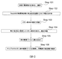
- FIG. 2 is a flowchart of the first embodiment.
- FIG. Schematic of the observation tool in liquid.
- the figure explaining the case where the microgrid 511 carrying the in-liquid observation tool 45 is observed as the sample 405.
- FIG. 1 is a diagram for explaining a flowchart of this embodiment.
- a solvent for example, ultrapure water
- an electrolyte are mixed and stirred (step 101). Stirring may be performed manually by an operator, or a stirrer may be used.
- a predetermined process is performed on the result of step 101.
- This predetermined process can be referred to as a microbubble generation process.
- the microbubble generation process is performed by putting the result of step 101 into a microbubble generator described later and applying a voltage (step 102).
- step 102 the mixed liquid of ultrapure water and the electrolyte contains bubbles, for example, microbubbles.
- the result of step 102 is referred to as microbubble water.
- the microbubbles may be referred to as, for example, fine bubbles, ultra fine bubbles, micro bubbles, nano bubbles, and micro nano bubbles.
- a fine bubble can be expressed as, for example, a bubble having a bubble diameter of several tens of microns or less, and more specifically, for example, a bubble having a bubble diameter of 1 micron or less.
- fine bubbles having a bubble diameter of 1 micron or less can be expressed as ultra fine bubbles.
- the ionic liquid is diluted with a solvent (for example, ultrapure water) (step 103).
- a solvent for example, ultrapure water
- the ionic liquid will be described.
- the ionic liquid is liquid at normal temperature and can be expressed as a liquid containing ions.
- the ionic liquid does not evaporate at all or hardly evaporates in the vacuum.
- An ionic liquid may contain a cation and an anion, for example.
- the ionic liquid may be hydrophilic or hydrophobic. Note that step 103 may be performed in parallel with steps 101 and 102.
- step 104 the microbubble water and the ionic liquid diluted in step 103 are mixed to prepare a specimen (step 104).
- step 105 the specimen prepared in step 104 is sealed in a submerged observation tool (details will be described later) (step 105).
- Step 106 an in-liquid observation tool enclosing the specimen is mounted on the sample holder and placed in the chamber of the charged particle beam apparatus to obtain an image (step 106).
- TEM transmission electron microscope
- STEM scanning transmission electron microscope
- SEM scanning electron microscope
- Step 106 can be expressed as, for example, an imaging process for obtaining a charged particle beam image of a specimen including a liquid subjected to a process for generating bubbles and an ionic liquid.
- the region showing microbubbles does not appear in the TEM image of the specimen that does not use ionic liquid.
- a region showing microbubbles appears in a TEM image of a specimen using an ionic liquid. This phenomenon is reproducible. This area is darker than its surroundings, and its shape is a substantial point or circle.
- the reason why the region showing the microbubbles can be confirmed in the TEM image of the sample using the ionic liquid is that, as a result of the interaction between the ionic liquid and the microbubble, the magnitude of the molecular weight of the ionic liquid and the other substance has a contrast. This is because it appears as a difference.
- the interaction between the ionic liquid and the microbubbles is, for example, when the ionic liquid 23 is adsorbed on the surface of the microbubbles 22 inside the specimen 21 as shown in FIG. At least one of the cases where the microbubbles 22 are replaced (FIG. 2B) is conceivable.
- the electrolyte can include at least one of carbonate ion, bicarbonate ion, nitrate ion, sulfate ion, chloride ion, perchlorate ion, hydroxide ion, sodium ion, potassium ion, but other known electrolytes are also employed. obtain.
- An arbitrary range can be adopted as the concentration range. As an example, the concentration range may be 0.1 to 1000 mM.
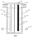
- FIG. 3 is a diagram for explaining a fine bubble generator.
- the fine bubble generator includes a container 208 for charging the electrolyte solution resulting from step 101, an anode 202, a cathode 204, an ion exchange membrane 205, a gas discharge port 206, an outlet 207, and a power source 209.
- the container 208 has a two-chamber structure by the ion exchange membrane 205, and the electrolytic solution is divided into the electrolytic solution 201 and the electrolytic solution 203.
- the side including the anode 202 can be expressed as an anode chamber, and the side including the cathode 204 can be expressed as a cathode chamber.
- the anode chamber and the cathode chamber include a supply port for supplying an electrolytic solution.
- Any material can be used for the ion exchange membrane 205. For example, a perfluorosulfonic acid material can be used.
- any material can be used for the anode 202.
- a conductive diamond catalyst doped with boron may be employed.
- cathode 204 Any material can be used for the cathode 204.
- platinum can be adopted.
- microbubbles having a predetermined particle diameter such as ozone microbubbles
- Hydrogen gas is generated on the cathode chamber side.
- the electrolytic solution containing microbubbles, that is, the above-described microbubble water is taken out from the outlet 207.
- the method of generating microbubbles is not limited to the above-described energization method (method 1), but a method using ultrasonic waves (method 2), a method using swirl flow (method 3), a pressure dissolution method (method 4), A method using a fine hole (method 5) can be arbitrarily adopted.
- the microbubbles can be expressed by the designation or the bubble diameter, but the bubbles generated by at least one of the above-described methods 1 to 5 can also be expressed as the microbubbles.
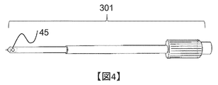
- FIG. 4 is a view for explaining a sample holder for a transmission electron microscope to be described later.
- An in-liquid observation tool 45 is present at the tip of the sample holder 301.
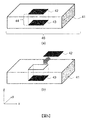
- FIG. 5 is a diagram for explaining the outline of the in-liquid observation tool 45.
- the in-liquid observation tool 45 includes a substrate 41, a space 44 formed so as to penetrate the substrate 41, a first observation window 42 disposed so as to close the opening of the space 44, and a second.
- the observation window 43 is included. At least one of the first observation window 42 and the second observation window 43 is removable.
- the first observation window 42 and the second observation window 43 are formed of a material that is transparent to charged particles.
- the material includes silicon nitride.
- the specimen is supplied to the space 44 and then sealed by closing the opening with the first observation window 42. As a result, the specimen is sealed in the in-liquid observation tool 45.
- FIG. 6 is a diagram for explaining the submerged observation tool 45 in detail from the Z direction in FIG.
- the submerged observation tool 45 includes a base 501, a first cover 506, a second cover 508, and a third cover 510.
- the base 501 includes a screw hole 502, a first O-ring 503, an electron beam passage portion 504, and a second O-ring 505.
- An observation window 507 is formed in the first cover 505.
- An observation window 509 is formed in the second cover 508.
- the observation window 507 and the observation window 509 are a material that is transparent to the charged particle beam, and is, for example, silicon nitride.
- the third cover 510 includes an opening 511 and a screw hole 512.
- the electron beam passage portion 504 is made of a material that is transparent to the opening or the charged particle beam.
- the electron beam passage 504 is inside the first O-ring 503.
- the first O-ring 503 is inside the second O-ring 505.
- the first cover 506 is smaller than the second cover 508, and the second cover 508 is smaller than the third cover.
- FIG. 7 is a diagram for explaining a flow (step 105 in FIG. 1) for enclosing a sample in the in-liquid observation tool in FIG.
- the first cover 506 is mounted on the base 501, and a sample is supplied onto the first cover 506 (step 601). More specifically, the first cover 506 covers the first O-ring 503 but is disposed inside the second O-ring 505. Further, the observation window 507 is inside the electron beam passage portion 504. In this state, the sample is supplied onto the first cover 506.
- the second cover 508 is disposed on the first cover 506 (step 602). More specifically, the second cover 508 is disposed inside the screw hole 502. Further, at least a part of the observation window 509 is in a relationship of overlapping a part of the observation window 507.
- the third cover 510 is disposed on the second cover 508 and fixed with the screws 601 (step 603).
- the observation window 509 is inside the opening 511.
- the screw hole 502 and the screw hole 512 have a matching positional relationship, and the third cover 508 can be fixed to the base 501 by the screw 601.
- the observation window 509 has the function of the first observation window 42 in FIG. 5, and the observation window 507 has the function of the second observation window 43 in FIG. Therefore, the charged particles supplied to the observation window 509 reach the sealed specimen, and the charged particles that have passed through the specimen are emitted outside the in-liquid observation tool 45 through the observation window 507.
- a charged particle beam image can be obtained by detecting electrons transmitted through the specimen with a detector or a camera described later.
- Such a submerged observation tool is, for example, a container that holds a specimen in a liquid state even in a vacuum chamber of a charged particle beam apparatus, is capable of transmitting charged particle beams, and is capable of transmitting electrons from the specimen. It can be expressed that there is.
- the submerged observation tool is not limited to the present embodiment, and any structure can be adopted.
- In-liquid observation tools are sometimes used for so-called in-situ observation.
- In-situ observation can be expressed as observation while applying energy to the specimen or observation that captures the change of the specimen with time.
- the in-liquid observation tool includes an in-situ observation mechanism.
- the in-situ observation mechanism include, for example, two or more electrodes that apply voltage to the specimen (voltage application process), a temperature control mechanism that changes the temperature of the specimen (temperature control process), and liquid or gas in the specimen.
- At least one of a supply mechanism for supplying a medium and a circulation mechanism (circulation process) including a pipe (medium supply process) and a flow path for circulating the sample may be used.
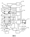
- FIG. 8 is a diagram for explaining the transmission electron microscope of this embodiment.
- the electron beam irradiated from the electron gun 401 is controlled by the high voltage control unit 402 such as ON / OFF and intensity.
- the electron beam emitted from the electron gun 401 is focused by the lens 403 and the position of the electron beam on the sample surface is adjusted by the deflection coil 404. As a result, the electron beam is irradiated to an arbitrary position on the surface of the sample 405.
- the lens 403 and the deflection coil 404 are controlled by a lens control unit 407 and a deflection coil control unit 408, respectively.
- the TEM image is formed on the fluorescent screen 410.
- a TEM image is formed on the film 413 in the camera 412 below, and a TEM image can be acquired.
- the camera 412 is controlled by a camera control unit 414.
- the camera 412 is not limited to a camera using a film, and the camera 412 includes a digital type camera using an image pickup device exemplified by a CCD or a CMOS instead of a film.
- the scanning image observation function (STEM function) is used.
- the electron beam is finely focused by the lens 403 and further deflected by the deflection coil 404.
- a desired two-dimensional area on the sample 405 is scanned by the electron beam.
- transmitted electrons, secondary electrons, scattered electrons, and the like are generated.
- a transmitted electron image, a secondary electron image, and a scattered electron image can be acquired.
- the generated scattered electrons are controlled such that the scattered angle always enters the annular dark field scanning image detector 409 by controlling the scattering angle by the lens 403 under the sample.
- the acquired image is supplied to each control unit.
- a scan image (dark field STEM image) synchronized with the electron beam scan is displayed on the personal computer 415.
- the control unit includes a memory storing a control algorithm, a CPU for executing the algorithm, and an I / O interface for transmitting and receiving signals.
- the personal computer 415 includes a memory that stores images, a CPU that performs predetermined processing such as reading data from the memory and writing data to the memory, a mouse, an input unit exemplified by a keyboard, and an output unit exemplified by a display. .
- the transmission electron microscope of this embodiment includes a bright-field scanning image detector 411 for acquiring a bright-field STEM image, an electron dose measuring device 421, an interface unit 417, an on / off switch 422, a water flow for cooling the lens body. 418, a mirror body cooling device control unit 419, and an external storage device 420 are included.
- the electron dose measuring device 421 is for measuring the electron dose irradiated to the fluorescent screen 410. In the case of an image shot with the film 413, a desired image can be obtained by controlling the electron dose and the exposure time using the electron dose measuring device 421.
- the camera control unit 414 controls the shutter of the camera 412.
- the interface unit 417 connects all the control units and the personal computer 415, and includes a bus and an I / O interface.
- the on / off switch 422 is a main power source. The device can be stopped by turning off the on / off switch 422.
- the mirror body cooling water flow 418 is a flow path of cooling water for cooling the mirror body.
- the mirror body cooling device control unit 419 controls the flow rate (l / min) of the cooling water.
- the external storage device 420 is a storage medium for storing information of each control unit and the obtained image, and may be a storage medium having a larger capacity than the memory inside the personal computer 415.
- the obtained images and moving images can be stored in at least one of the memory inside the personal computer 415 and the external storage device 420.
- the CPU in the personal computer 415 can perform predetermined image processing on the obtained images and moving images.
- the in-liquid observation tool 45 can be directly connected to or formed at the tip of the sample holder 301, it is mounted on the tip of the sample holder 301 via a microgrid 511 which is a collection of minute openings as shown in FIG. You can also.
- the electron beam 801 passes through the observation window 42 and reaches the sample.
- the transmitted electrons 802 that have passed through the specimen pass through the opening in the microgrid 511 and the observation window 43 opposite to the observation window 42. By detecting the transmitted electrons 802, a TEM image of the specimen can be acquired.
- FIG. 10A illustrates a GUI displayed by the output unit of the personal computer 415.
- a TEM image 902 is displayed on the GUI 901.
- the TEM image 902 includes microbubble regions 903 and 904.
- the operator can draw a line segment 908 from an arbitrary start point 905 to an arbitrary end point 906 of the microbubble region 903 with the pointer 907.
- the CPU in the personal computer 415 obtains the length of the line segment 908 on the sample based on the model shown in FIG. The obtained length is displayed in window 910.
- a similar procedure can be applied to the fine bubble area 904.
- the coordinates of the start point 905 and the end point 906 can be obtained from selection by the pointer 907. Therefore, if L and M are known, the length of the line segment 908 on the sample can be obtained. In this way, the length of the line segment 908 on the sample can be obtained from the coordinates of the start point 905, the coordinates of the end point 906, information on the pixel size, and information on the magnification.
- L and M are known, the length of the line segment 908 on the sample can be obtained.
- the length of the line segment 908 on the sample can be obtained from the coordinates of the start point 905, the coordinates of the end point 906, information on the pixel size, and information on the magnification.
- the time scale 911 can be displayed.
- the time scale 911 means moving image capturing time.
- An arbitrary imaging time can be specified by moving the bar 913 in the direction of the arrow 912 with the pointer 907.
- the CPU reads a TEM image at the designated time from the memory and displays it on the GUI 901.
- the operator can evaluate the size of the microbubbles at an arbitrary time.
- the microbubble evaluation method is not limited to the above method.
- the process of obtaining the dimension of microbubbles can be expressed as a measurement process of obtaining the dimension of a predetermined region in the charged particle image, for example.
- the ionic liquid by using the ionic liquid, it is possible to check bubbles in the liquid, for example, microbubbles. More specifically, the microbubbles in the liquid can be confirmed without freezing the specimen. And it becomes possible by using this image to evaluate the dimension of the microbubble in a liquid.
- hydrophilic ionic liquids include tetrafluoroboric acid 1-ethyl-3-methylimidazolium, trifluoromethanesulfonic acid 1-ethyl-3-methylimidazolium, tetrafluoroboric acid 1-butyl-3-methylimidazole 1-butyl-3-methylimidazolium bromide, trifluoromethanesulfonic acid, 1-hexyl-3-methylimidazolium bromide, 1-hexyl-3-methylimidazolium chloride, 1-decyl-3-methylimidazolium chloride, etc. Is mentioned.
- hydrophobic ionic liquid examples include 1-butyl-3-methylimidazolium bis (trifluoromethanesulfonyl) imide (BMI-TFSI).
- the present invention is not limited to the embodiments.
- the steps in FIGS. 1 and 6 are not necessarily in an essential relationship.
- the configuration of the charged particle beam apparatus is not limited to FIG. It is also within the scope of the present disclosure to acquire a moving image by continuously acquiring images exemplified by the TEM image.
- the present invention is widely applicable to specimen preparation and bubble evaluation.
- the form of applying the ionic liquid to the liquid that will contain bubbles is within the scope of the disclosure herein.
- the idea that an observer can discriminate the boundary between a predetermined region in a liquid image that will contain bubbles and the surrounding region is also within the scope of the disclosure of this specification.
Landscapes
- Chemical & Material Sciences (AREA)
- Analytical Chemistry (AREA)
- Physics & Mathematics (AREA)
- Health & Medical Sciences (AREA)
- Life Sciences & Earth Sciences (AREA)
- Biochemistry (AREA)
- General Health & Medical Sciences (AREA)
- General Physics & Mathematics (AREA)
- Immunology (AREA)
- Pathology (AREA)
- Analysing Materials By The Use Of Radiation (AREA)
Abstract
Description
202・・・陽極
203・・・電解液
204・・・陰極
205・・・イオン交換膜
206・・・ガス放出口、
207・・・取出口
Claims (13)
- 気泡を発生させる処理を施した液体とイオン液体とを含む標本の荷電粒子線像を得る撮像工程を含むことを特徴とする標本の観察方法。
- 請求項1に記載の観察方法において、
前記標本を荷電粒子に対して透明な部分を含む容器に封入する封入工程を含み、
前記封入工程は前記撮像工程の前に行われることを特徴とする標本の観察方法。 - 請求項1に記載の観察方法において、
前記イオン液体はカチオン、及びアニオンを含むことを特徴とする標本の観察方法。 - 請求項1に記載の観察方法において、
前記気泡はファインバブルであることを特徴とする標本の観察方法。 - 請求項1に記載の観察方法において、
前記荷電粒子線像中の所定の領域の寸法を得る計測工程を含み、
前記所定の領域はその周囲に比べて暗いことを特徴とする標本の観察方法。 - 請求項1に記載の観察方法において、
前記撮像工程は前記標本の動画を得る動画取得工程を含むことを特徴とする標本の観察方法。 - 請求項6に記載の観察方法において、
前記撮像工程は前記標本のその場観察工程を含むことを特徴とする標本の観察方法。 - 請求項6に記載の観察方法において、
前記その場観察は前記標本に電圧を印加する電圧印加工程を含む標本の観察方法。 - 請求項6に記載の観察方法において、
前記その場観察は前記標本の温度を変更する温度制御工程を含む標本の観察方法。 - 請求項6に記載の観察方法において、
前記その場観察は前記標本へ媒体を供給する媒体供給工程を含む標本の観察方法。 - 請求項6に記載の観察方法において、
前記その場観察は前記標本を循環させる循環工程を含む標本の観察方法。 - 請求項1に記載の観察方法において、
前記荷電粒子線像は透過電子像であることを特徴とする標本の観察方法。 - 請求項1に記載の観察方法において、
前記荷電粒子線像は走査電子顕微鏡像であることを特徴とする標本の観察方法。
Priority Applications (5)
| Application Number | Priority Date | Filing Date | Title |
|---|---|---|---|
| CN201680083602.5A CN108780054B (zh) | 2016-03-18 | 2016-03-18 | 样本的观察方法 |
| JP2018500952A JP6335411B2 (ja) | 2016-03-18 | 2016-03-18 | 標本の観察方法 |
| PCT/JP2016/058622 WO2017158806A1 (ja) | 2016-03-18 | 2016-03-18 | 標本の観察方法 |
| DE112016006464.0T DE112016006464T5 (de) | 2016-03-18 | 2016-03-18 | Probenbeobachtungsverfahren |
| US16/085,743 US10852253B2 (en) | 2016-03-18 | 2016-03-18 | Specimen observation method |
Applications Claiming Priority (1)
| Application Number | Priority Date | Filing Date | Title |
|---|---|---|---|
| PCT/JP2016/058622 WO2017158806A1 (ja) | 2016-03-18 | 2016-03-18 | 標本の観察方法 |
Publications (1)
| Publication Number | Publication Date |
|---|---|
| WO2017158806A1 true WO2017158806A1 (ja) | 2017-09-21 |
Family
ID=59852177
Family Applications (1)
| Application Number | Title | Priority Date | Filing Date |
|---|---|---|---|
| PCT/JP2016/058622 Ceased WO2017158806A1 (ja) | 2016-03-18 | 2016-03-18 | 標本の観察方法 |
Country Status (5)
| Country | Link |
|---|---|
| US (1) | US10852253B2 (ja) |
| JP (1) | JP6335411B2 (ja) |
| CN (1) | CN108780054B (ja) |
| DE (1) | DE112016006464T5 (ja) |
| WO (1) | WO2017158806A1 (ja) |
Cited By (1)
| Publication number | Priority date | Publication date | Assignee | Title |
|---|---|---|---|---|
| JP2019100948A (ja) * | 2017-12-06 | 2019-06-24 | 猛 大平 | 液体内の微細気泡の存在を確認する方法及び装置 |
Families Citing this family (1)
| Publication number | Priority date | Publication date | Assignee | Title |
|---|---|---|---|---|
| JP7138550B2 (ja) * | 2018-11-29 | 2022-09-16 | 東京エレクトロン株式会社 | 基板処理装置 |
Citations (4)
| Publication number | Priority date | Publication date | Assignee | Title |
|---|---|---|---|---|
| JP2009266741A (ja) * | 2008-04-28 | 2009-11-12 | Hitachi High-Technologies Corp | 透過型電子顕微鏡、及び試料観察方法 |
| JP3165429U (ja) * | 2010-11-02 | 2011-01-20 | 誠 山口 | 微細バブル観察用試料ホルダー |
| US20120120226A1 (en) * | 2010-11-17 | 2012-05-17 | Vanderbilt University | Transmission electron microscopy for imaging live cells |
| JP2016095183A (ja) * | 2014-11-13 | 2016-05-26 | 国立大学法人大阪大学 | 液体に含まれる超微細バブルの測定方法及びその測定装置 |
Family Cites Families (6)
| Publication number | Priority date | Publication date | Assignee | Title |
|---|---|---|---|---|
| JP3165429B2 (ja) * | 1990-07-13 | 2001-05-14 | オリンパス光学工業株式会社 | 凝集像判定方法 |
| JP4151681B2 (ja) * | 2005-07-19 | 2008-09-17 | 株式会社日立製作所 | 微細気泡生成装置及びその方法 |
| JP4799690B2 (ja) | 2009-12-01 | 2011-10-26 | 国立大学法人北海道大学 | 電子顕微鏡による試料観察用の液状媒体とそれを用いた電子顕微鏡による試料観察方法 |
| JP5544181B2 (ja) | 2010-01-29 | 2014-07-09 | 公立大学法人 滋賀県立大学 | オゾン微細気泡の電解合成方法 |
| JP5542749B2 (ja) * | 2011-06-30 | 2014-07-09 | 株式会社日立ハイテクノロジーズ | 試料の作製装置,作製方法、及びそれを用いた荷電粒子線装置 |
| DE112014002043T5 (de) * | 2013-05-30 | 2016-01-14 | Hitachi High-Technologies Corporation | Mit einem Strahl geladener Teilchen arbeitende Vorrichtung und Probenbeobachtungsverfahren |
-
2016
- 2016-03-18 US US16/085,743 patent/US10852253B2/en active Active
- 2016-03-18 CN CN201680083602.5A patent/CN108780054B/zh active Active
- 2016-03-18 WO PCT/JP2016/058622 patent/WO2017158806A1/ja not_active Ceased
- 2016-03-18 DE DE112016006464.0T patent/DE112016006464T5/de active Pending
- 2016-03-18 JP JP2018500952A patent/JP6335411B2/ja active Active
Patent Citations (4)
| Publication number | Priority date | Publication date | Assignee | Title |
|---|---|---|---|---|
| JP2009266741A (ja) * | 2008-04-28 | 2009-11-12 | Hitachi High-Technologies Corp | 透過型電子顕微鏡、及び試料観察方法 |
| JP3165429U (ja) * | 2010-11-02 | 2011-01-20 | 誠 山口 | 微細バブル観察用試料ホルダー |
| US20120120226A1 (en) * | 2010-11-17 | 2012-05-17 | Vanderbilt University | Transmission electron microscopy for imaging live cells |
| JP2016095183A (ja) * | 2014-11-13 | 2016-05-26 | 国立大学法人大阪大学 | 液体に含まれる超微細バブルの測定方法及びその測定装置 |
Non-Patent Citations (1)
| Title |
|---|
| TAKANORI NAKAYAMA ET AL: "Observation of ionic 1-13 liquid interface in a nanotube", THE JAPAN SOCIETY OF MECHANICAL ENGINEERS KYUSHU BRANCH KOEN RONBUNSHU, vol. 118, no. 1, 17 March 2011 (2011-03-17), pages 261 - 262 * |
Cited By (2)
| Publication number | Priority date | Publication date | Assignee | Title |
|---|---|---|---|---|
| JP2019100948A (ja) * | 2017-12-06 | 2019-06-24 | 猛 大平 | 液体内の微細気泡の存在を確認する方法及び装置 |
| JP6996741B2 (ja) | 2017-12-06 | 2022-01-17 | 大平研究所株式会社 | 液体内の微細気泡の存在を確認する装置 |
Also Published As
| Publication number | Publication date |
|---|---|
| JPWO2017158806A1 (ja) | 2018-05-24 |
| DE112016006464T5 (de) | 2018-11-08 |
| JP6335411B2 (ja) | 2018-05-30 |
| CN108780054B (zh) | 2022-06-24 |
| US10852253B2 (en) | 2020-12-01 |
| CN108780054A (zh) | 2018-11-09 |
| US20190051489A1 (en) | 2019-02-14 |
Similar Documents
| Publication | Publication Date | Title |
|---|---|---|
| US9466460B2 (en) | Charged particle-beam device and specimen observation method | |
| US9939363B2 (en) | Particle tracking analysis method using scattered light (PTA) and device for detecting and identifying particles of a nanometric order of magnitude in liquids of all types | |
| EP3172758B1 (en) | Method for inspecting a sample using an assembly comprising a scanning electron microscope and a light microscope | |
| JP6346016B2 (ja) | 放射線分析装置 | |
| US20150214004A1 (en) | Method for preparing and analyzing an object as well as particle beam device for performing the method | |
| US9455120B2 (en) | Particle beam device and method for processing and/or analyzing a sample | |
| JP6216651B2 (ja) | 荷電粒子線装置、画像生成方法、観察システム | |
| JP2019145499A (ja) | 走査透過荷電粒子顕微鏡におけるインテリジェントプレスキャン | |
| JP6335411B2 (ja) | 標本の観察方法 | |
| US9857318B2 (en) | Method for generating image data relating to an object and particle beam device for carrying out this method | |
| JP2007188905A (ja) | 荷電粒子線装置用試料ホールダ | |
| JP6637103B2 (ja) | 標本の観察方法 | |
| US9214316B2 (en) | Composite charged particle beam apparatus | |
| CN115527824A (zh) | 用于三维重建的带电粒子显微镜扫描掩模 | |
| CN113287002A (zh) | 单晶x射线结构解析装置以及试样保持架 | |
| JP2022110137A (ja) | コロイド中のナノ粒子のサイズを決定するための改良された方法 | |
| JP5489412B2 (ja) | 蛍光x線分析機能付き高分解能x線顕微装置 | |
| Holm | A Brief Overview of Scanning Transmission Electron Microscopy in a Scanning Electron Microscope | |
| de Jonge et al. | Resolution in liquid cell experiments | |
| CN111146062B (zh) | 电子显微镜和图像处理方法 | |
| JP7239926B2 (ja) | 粒子の観察方法 | |
| Veselov et al. | Automatic system for single ion/single cell irradiation based on Cracow microprobe | |
| Shiina et al. | Fresnel diffraction correction by phase-considered iteration procedure in soft X-ray projection microscopy | |
| JP2023063678A (ja) | 液中試料用顕微鏡装置 | |
| JP2014082029A (ja) | イオン液体の評価方法および荷電粒子線装置 |
Legal Events
| Date | Code | Title | Description |
|---|---|---|---|
| ENP | Entry into the national phase |
Ref document number: 2018500952 Country of ref document: JP Kind code of ref document: A |
|
| WWE | Wipo information: entry into national phase |
Ref document number: 112016006464 Country of ref document: DE |
|
| 121 | Ep: the epo has been informed by wipo that ep was designated in this application |
Ref document number: 16894424 Country of ref document: EP Kind code of ref document: A1 |
|
| 122 | Ep: pct application non-entry in european phase |
Ref document number: 16894424 Country of ref document: EP Kind code of ref document: A1 |