WO2017154833A1 - 情報処理装置及びプログラム - Google Patents
情報処理装置及びプログラム Download PDFInfo
- Publication number
- WO2017154833A1 WO2017154833A1 PCT/JP2017/008771 JP2017008771W WO2017154833A1 WO 2017154833 A1 WO2017154833 A1 WO 2017154833A1 JP 2017008771 W JP2017008771 W JP 2017008771W WO 2017154833 A1 WO2017154833 A1 WO 2017154833A1
- Authority
- WO
- WIPO (PCT)
- Prior art keywords
- vehicle
- image
- display
- state
- information processing
- Prior art date
- Legal status (The legal status is an assumption and is not a legal conclusion. Google has not performed a legal analysis and makes no representation as to the accuracy of the status listed.)
- Ceased
Links
Images

Classifications
-
- H—ELECTRICITY
- H04—ELECTRIC COMMUNICATION TECHNIQUE
- H04N—PICTORIAL COMMUNICATION, e.g. TELEVISION
- H04N7/00—Television systems
- H04N7/18—Closed-circuit television [CCTV] systems, i.e. systems in which the video signal is not broadcast
- H04N7/181—Closed-circuit television [CCTV] systems, i.e. systems in which the video signal is not broadcast for receiving images from a plurality of remote sources
-
- G—PHYSICS
- G06—COMPUTING OR CALCULATING; COUNTING
- G06V—IMAGE OR VIDEO RECOGNITION OR UNDERSTANDING
- G06V20/00—Scenes; Scene-specific elements
- G06V20/50—Context or environment of the image
- G06V20/56—Context or environment of the image exterior to a vehicle by using sensors mounted on the vehicle
-
- B—PERFORMING OPERATIONS; TRANSPORTING
- B60—VEHICLES IN GENERAL
- B60R—VEHICLES, VEHICLE FITTINGS, OR VEHICLE PARTS, NOT OTHERWISE PROVIDED FOR
- B60R1/00—Optical viewing arrangements; Real-time viewing arrangements for drivers or passengers using optical image capturing systems, e.g. cameras or video systems specially adapted for use in or on vehicles
- B60R1/20—Real-time viewing arrangements for drivers or passengers using optical image capturing systems, e.g. cameras or video systems specially adapted for use in or on vehicles
- B60R1/22—Real-time viewing arrangements for drivers or passengers using optical image capturing systems, e.g. cameras or video systems specially adapted for use in or on vehicles for viewing an area outside the vehicle, e.g. the exterior of the vehicle
- B60R1/23—Real-time viewing arrangements for drivers or passengers using optical image capturing systems, e.g. cameras or video systems specially adapted for use in or on vehicles for viewing an area outside the vehicle, e.g. the exterior of the vehicle with a predetermined field of view
- B60R1/27—Real-time viewing arrangements for drivers or passengers using optical image capturing systems, e.g. cameras or video systems specially adapted for use in or on vehicles for viewing an area outside the vehicle, e.g. the exterior of the vehicle with a predetermined field of view providing all-round vision, e.g. using omnidirectional cameras
-
- B—PERFORMING OPERATIONS; TRANSPORTING
- B60—VEHICLES IN GENERAL
- B60R—VEHICLES, VEHICLE FITTINGS, OR VEHICLE PARTS, NOT OTHERWISE PROVIDED FOR
- B60R1/00—Optical viewing arrangements; Real-time viewing arrangements for drivers or passengers using optical image capturing systems, e.g. cameras or video systems specially adapted for use in or on vehicles
- B60R1/20—Real-time viewing arrangements for drivers or passengers using optical image capturing systems, e.g. cameras or video systems specially adapted for use in or on vehicles
- B60R1/22—Real-time viewing arrangements for drivers or passengers using optical image capturing systems, e.g. cameras or video systems specially adapted for use in or on vehicles for viewing an area outside the vehicle, e.g. the exterior of the vehicle
- B60R1/28—Real-time viewing arrangements for drivers or passengers using optical image capturing systems, e.g. cameras or video systems specially adapted for use in or on vehicles for viewing an area outside the vehicle, e.g. the exterior of the vehicle with an adjustable field of view
-
- B—PERFORMING OPERATIONS; TRANSPORTING
- B60—VEHICLES IN GENERAL
- B60W—CONJOINT CONTROL OF VEHICLE SUB-UNITS OF DIFFERENT TYPE OR DIFFERENT FUNCTION; CONTROL SYSTEMS SPECIALLY ADAPTED FOR HYBRID VEHICLES; ROAD VEHICLE DRIVE CONTROL SYSTEMS FOR PURPOSES NOT RELATED TO THE CONTROL OF A PARTICULAR SUB-UNIT
- B60W40/00—Estimation or calculation of non-directly measurable driving parameters for road vehicle drive control systems not related to the control of a particular sub unit, e.g. by using mathematical models
- B60W40/10—Estimation or calculation of non-directly measurable driving parameters for road vehicle drive control systems not related to the control of a particular sub unit, e.g. by using mathematical models related to vehicle motion
- B60W40/105—Speed
-
- G—PHYSICS
- G06—COMPUTING OR CALCULATING; COUNTING
- G06T—IMAGE DATA PROCESSING OR GENERATION, IN GENERAL
- G06T15/00—Three-dimensional [3D] image rendering
- G06T15/10—Geometric effects
- G06T15/20—Perspective computation
-
- H—ELECTRICITY
- H04—ELECTRIC COMMUNICATION TECHNIQUE
- H04N—PICTORIAL COMMUNICATION, e.g. TELEVISION
- H04N7/00—Television systems
- H04N7/18—Closed-circuit television [CCTV] systems, i.e. systems in which the video signal is not broadcast
-
- B—PERFORMING OPERATIONS; TRANSPORTING
- B60—VEHICLES IN GENERAL
- B60R—VEHICLES, VEHICLE FITTINGS, OR VEHICLE PARTS, NOT OTHERWISE PROVIDED FOR
- B60R2300/00—Details of viewing arrangements using cameras and displays, specially adapted for use in a vehicle
- B60R2300/10—Details of viewing arrangements using cameras and displays, specially adapted for use in a vehicle characterised by the type of camera system used
- B60R2300/105—Details of viewing arrangements using cameras and displays, specially adapted for use in a vehicle characterised by the type of camera system used using multiple cameras
-
- B—PERFORMING OPERATIONS; TRANSPORTING
- B60—VEHICLES IN GENERAL
- B60R—VEHICLES, VEHICLE FITTINGS, OR VEHICLE PARTS, NOT OTHERWISE PROVIDED FOR
- B60R2300/00—Details of viewing arrangements using cameras and displays, specially adapted for use in a vehicle
- B60R2300/30—Details of viewing arrangements using cameras and displays, specially adapted for use in a vehicle characterised by the type of image processing
- B60R2300/303—Details of viewing arrangements using cameras and displays, specially adapted for use in a vehicle characterised by the type of image processing using joined images, e.g. multiple camera images
-
- B—PERFORMING OPERATIONS; TRANSPORTING
- B60—VEHICLES IN GENERAL
- B60R—VEHICLES, VEHICLE FITTINGS, OR VEHICLE PARTS, NOT OTHERWISE PROVIDED FOR
- B60R2300/00—Details of viewing arrangements using cameras and displays, specially adapted for use in a vehicle
- B60R2300/60—Details of viewing arrangements using cameras and displays, specially adapted for use in a vehicle characterised by monitoring and displaying vehicle exterior scenes from a transformed perspective
- B60R2300/602—Details of viewing arrangements using cameras and displays, specially adapted for use in a vehicle characterised by monitoring and displaying vehicle exterior scenes from a transformed perspective with an adjustable viewpoint
- B60R2300/605—Details of viewing arrangements using cameras and displays, specially adapted for use in a vehicle characterised by monitoring and displaying vehicle exterior scenes from a transformed perspective with an adjustable viewpoint the adjustment being automatic
-
- B—PERFORMING OPERATIONS; TRANSPORTING
- B60—VEHICLES IN GENERAL
- B60R—VEHICLES, VEHICLE FITTINGS, OR VEHICLE PARTS, NOT OTHERWISE PROVIDED FOR
- B60R2300/00—Details of viewing arrangements using cameras and displays, specially adapted for use in a vehicle
- B60R2300/60—Details of viewing arrangements using cameras and displays, specially adapted for use in a vehicle characterised by monitoring and displaying vehicle exterior scenes from a transformed perspective
- B60R2300/607—Details of viewing arrangements using cameras and displays, specially adapted for use in a vehicle characterised by monitoring and displaying vehicle exterior scenes from a transformed perspective from a bird's eye viewpoint
-
- B—PERFORMING OPERATIONS; TRANSPORTING
- B60—VEHICLES IN GENERAL
- B60R—VEHICLES, VEHICLE FITTINGS, OR VEHICLE PARTS, NOT OTHERWISE PROVIDED FOR
- B60R2300/00—Details of viewing arrangements using cameras and displays, specially adapted for use in a vehicle
- B60R2300/70—Details of viewing arrangements using cameras and displays, specially adapted for use in a vehicle characterised by an event-triggered choice to display a specific image among a selection of captured images
-
- B—PERFORMING OPERATIONS; TRANSPORTING
- B60—VEHICLES IN GENERAL
- B60R—VEHICLES, VEHICLE FITTINGS, OR VEHICLE PARTS, NOT OTHERWISE PROVIDED FOR
- B60R2300/00—Details of viewing arrangements using cameras and displays, specially adapted for use in a vehicle
- B60R2300/80—Details of viewing arrangements using cameras and displays, specially adapted for use in a vehicle characterised by the intended use of the viewing arrangement
- B60R2300/802—Details of viewing arrangements using cameras and displays, specially adapted for use in a vehicle characterised by the intended use of the viewing arrangement for monitoring and displaying vehicle exterior blind spot views
-
- B—PERFORMING OPERATIONS; TRANSPORTING
- B60—VEHICLES IN GENERAL
- B60R—VEHICLES, VEHICLE FITTINGS, OR VEHICLE PARTS, NOT OTHERWISE PROVIDED FOR
- B60R2300/00—Details of viewing arrangements using cameras and displays, specially adapted for use in a vehicle
- B60R2300/80—Details of viewing arrangements using cameras and displays, specially adapted for use in a vehicle characterised by the intended use of the viewing arrangement
- B60R2300/806—Details of viewing arrangements using cameras and displays, specially adapted for use in a vehicle characterised by the intended use of the viewing arrangement for aiding parking
Definitions
- This disclosure relates to a technique for photographing and displaying the vicinity of a vehicle.
- Patent Document 1 proposes a technique for displaying an image of a vehicle viewed from diagonally above.
- the inventor has found a problem that the area around the vehicle that the vehicle occupant desires to see changes as the traveling state of the vehicle changes. It is desirable that the present disclosure provide a technique for displaying an image showing an appropriate range around the vehicle.
- a first aspect of the present disclosure is an information processing apparatus including a state determination unit, a speed detection unit, and a display control unit.
- the state determination unit is configured to determine a control state by a control unit that controls the output direction of the driving force by the traveling drive source of the vehicle.
- the control unit is configured to control the output direction of the driving force by the traveling drive source of the vehicle.
- the speed detection unit is configured to detect the traveling speed of the vehicle.
- the display control unit displays on the display device one or more peripheral images determined according to the control state determined by the state determination unit and the traveling speed detected by the speed detection unit from among the plurality of peripheral images. It is configured to let you.
- a plurality of surrounding images are images showing the surroundings of the vehicle based on images taken by one or more cameras that capture the surroundings of the vehicle, and are images that differ in at least one of the viewpoint and the display range, respectively. is there.
- the display device displays a peripheral image indicating a range suitable for the traveling state of the vehicle based on the output direction of the driving force by the traveling driving source of the vehicle and the traveling speed of the vehicle. Can do. Therefore, the passenger of the vehicle can visually recognize an image corresponding to the situation.
- a second aspect of the present disclosure is a program that causes a computer to function as a state determination unit, a speed detection unit, and a display control unit.
- the functions of the state determination unit, the speed detection unit, and the display control unit are the same as those of the state determination unit, the speed detection unit, and the display control unit included in the information processing apparatus of the first aspect described above.
- the image display system 1 is a system used by being mounted on a vehicle such as an automobile. As shown in FIG. 1, the image display system 1 includes a front camera 3a, a rear camera 3b, a left camera 3c, a right camera 3d, a display device 5, and an electronic control unit (hereinafter referred to as ECU) 7 mounted on a vehicle. And. In the following description, the camera 3 may include the four cameras 3a, 3b, 3c, and 3d.
- the ECU 7 corresponds to an information processing device.
- the camera 3 is an imaging device provided in the vehicle.
- a known CCD image sensor or CMOS image sensor can be used as the camera 3.
- Each of the cameras 3a, 3b, 3c, and 3d captures the periphery of the vehicle at a predetermined time interval (1/15 s as an example), and outputs the captured image to the ECU 7.
- the front camera 3a, the rear camera 3b, the left camera 3c, and the right camera 3d are disposed so as to photograph the front, rear, left, and right sides of the vehicle, respectively.
- the display device 5 is a device having a display screen such as liquid crystal or organic EL capable of displaying an image.
- the display device 5 displays an image according to a signal input from the ECU 7.
- the ECU 7 includes a first input processing unit 11, a storage device 13, a second input processing unit 15, an output signal processing unit 17, and an image processing unit 19.
- the first input processing unit 11 converts an analog signal of a captured image input from the camera 3 into a digital signal and outputs the digital signal to the image processing unit 19.
- the storage device 13 is a device constituting a storage area capable of storing information. Parameters such as the installation position and angle of each camera 3 are stored in a storage area formed by the storage device 13, and the parameters are read by the image processing unit 19 when necessary.
- the second input processing unit 15 is connected to the in-vehicle network 9.
- the second input processing unit 15 acquires signals output from the shift sensor 9 a and the vehicle speed sensor 9 b connected to the in-vehicle network 9 and outputs the signals to the image processing unit 19.
- the shift sensor 9a is a sensor that outputs in accordance with the position where the selector 31 provided in the vicinity of the driver's seat has moved by the driver's operation, that is, the shift range set by the driver's operation.
- the type of the vehicle transmission 33 may be an automatic transmission.
- the selector 31 is an operation part such as a lever for operating the transmission 33 of the vehicle.
- the driver operates the selector 31 to change the shift range into a parking range (hereinafter referred to as P range), a reverse range (hereinafter referred to as R range), a neutral range (hereinafter referred to as N range), and a drive range (hereinafter referred to as D range).
- P range parking range
- R range reverse range
- N range a neutral range
- D range drive range
- the transmission 33 corresponds to the output control device.
- the vehicle speed sensor 9b is a sensor that outputs a signal corresponding to the traveling speed of the vehicle.
- the output signal processing unit 17 converts the digital signal of the image data output from the image processing unit 19 into an analog signal and outputs the analog signal to the display device 5.
- the display device 5 displays an image based on the received signal.
- the image processing unit 19 is mainly configured by a known microcomputer having a CPU 21 and a semiconductor memory (hereinafter referred to as a memory 23) such as a RAM, a ROM, and a flash memory.
- a memory 23 such as a RAM, a ROM, and a flash memory.
- Various functions of the image processing unit 19 are realized by the CPU 21 executing a program stored in a non-transitional physical recording medium.
- the memory 23 corresponds to a non-transitional tangible recording medium that stores a program. Further, by executing this program, a method corresponding to the program is executed. Note that the number of microcomputers constituting the image processing unit 19 may be one or plural.
- the image processing unit 19 includes a state determination unit 25, a speed detection unit 26, an image generation unit 27, and a display control unit. 28.
- the method of realizing these elements constituting the image processing unit 19 is not limited to software, and some or all of the elements may be realized using hardware that combines a logic circuit, an analog circuit, and the like. .
- the state determination unit 25 determines the control state of the transmission 33 based on the signal output from the shift sensor 9a.
- the control state of the transmission 33 is a state of control of the output direction of the driving force by the engine that is the driving source of the vehicle.
- the output direction of the driving force described above is a direction in which the vehicle can be advanced by receiving the driving force of the engine, and is either forward or backward. This output direction does not mean the direction in which the vehicle is currently traveling. For example, even if the traveling speed of the vehicle is 0 km / h, the output direction is forward if the state of the transmission 33 is a state in which the vehicle moves forward when the accelerator is depressed by the driver.
- control state of the transmission 33 described above includes (i) a state in which driving force is transmitted so as to advance the vehicle forward, (ii) a state in which transmission of driving force is not performed, and (iii) a state in which the vehicle is advanced rearward.
- the state that transmits the driving force to the motor can be roughly divided into three. Of course, it may be further classified. These states vary depending on the connection state of gears constituting the transmission 33 and the like.
- the state of the transmission 33 is a control state in which power is transmitted so that the vehicle travels forward.
- the state of the transmission 33 is a control state in which power transmission is not performed.
- the state of the transmission 33 is a control state in which power is transmitted so that the vehicle travels backward.
- the speed detector 26 detects the traveling speed of the vehicle based on the signal output from the vehicle speed sensor 9b.
- the image generation unit 27 is different from the viewpoint of the captured image captured by each of the cameras 3a, 3b, 3c, and 3d based on the image captured by one or more of the cameras 3a, 3b, 3c, and 3d. Generate one or more images of the viewpoint. Note that the parameters of the camera 3 stored in the storage device 13 are used when generating the one or more images.
- the display control unit 28 causes the display device 5 to display a peripheral image.
- the peripheral image will be described below.
- the peripheral image is an image showing the periphery of the vehicle, and is an image generated by the image generation unit 27 based on an image captured by the camera 3 that captures the periphery of the vehicle. As described above, the image generation unit 27 generates an image of a viewpoint different from the viewpoints of the four cameras 3. Each of the images generated by the image generation unit 27 is a peripheral image.
- the viewpoint mentioned here is a position that becomes a stance point when viewing the photographed object. Since a technique for generating images of viewpoints different from those viewpoints based on images taken from a plurality of different viewpoints is a known technique, the description thereof is omitted.
- the positions of the viewpoints of the peripheral images generated by the image generation unit 27 are set at four locations with the vehicle 101 as a reference.
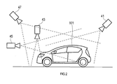
- the first virtual viewpoint 41 is a viewpoint in which the vehicle 101 is looked down obliquely forward from behind the vehicle 101 on which the image display system 1 is mounted.
- the second virtual viewpoint 43 is a viewpoint that looks down from above the front end of the vehicle 101.
- the third virtual viewpoint 45 is a viewpoint for viewing the vehicle 101 rearward from the front of the vehicle 101.
- the fourth virtual viewpoint 47 is a viewpoint in which the vehicle 101 is looked down obliquely rearward from above and in front of the vehicle 101.
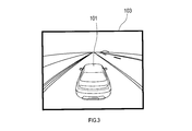
- FIG. 3 is a diagram showing a rear viewpoint image 103 that is a peripheral image viewed from the first virtual viewpoint 41.
- the rear viewpoint image 103 is generated by synthesizing the captured images of the four cameras 3a, 3b, 3c, and 3d. Since the vehicle 101 itself is not photographed by the camera 3, an image representing the vehicle 101 prepared in advance is used for synthesis. This also applies to the image described later.
- the passenger can visually recognize the front of the vehicle 101 widely, and can easily understand the positional relationship between the obstacle and the vehicle shown in the photographed image and the vehicle 101. That is, the rear viewpoint image 103 is an image suitable for confirming the periphery of a relatively wide range centering on the front when the vehicle is stopped, such as when driving is started and when the vehicle is stopped.
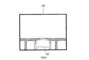
- FIG. 4 is a diagram showing an upper viewpoint image 105 that is a peripheral image viewed from the second virtual viewpoint 43.
- the upper viewpoint image 105 is generated by converting the viewpoint of the captured image of the front camera 3a.
- an area that is a road surface in front of the vehicle 101 and includes an area that is a driver's blind spot is displayed.
- the passenger can acquire information around the front end of the vehicle 101. That is, the upper viewpoint image 105 is a suitable image when the vehicle starts to move forward or when the vehicle is traveling slowly in order to avoid contact with an obstacle.
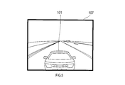
- FIG. 5 is a diagram illustrating a front viewpoint image 107 that is a peripheral image viewed from the third virtual viewpoint 45.
- the front viewpoint image 107 is generated by synthesizing the captured images of the rear camera 3b, the left camera 3c, and the right camera 3d.
- the passenger can visually recognize an image that displays the rear and side of the vehicle, such as the display of the rearview mirror and the display of the side mirror. It is possible to easily confirm the other vehicle located. That is, the front viewpoint image 107 is an image suitable for, for example, changing lanes.
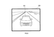
- FIG. 6 is a diagram showing a front overhead viewpoint image 109 that is a peripheral image viewed from the fourth virtual viewpoint 47.
- the front bird's-eye view image 109 is generated by synthesizing the captured images of the four cameras 3a, 3b, 3c, and 3d.
- the passenger can widely check the periphery of the vehicle centering on the rear of the vehicle, and the positional relationship between the vehicle 101 and the white lines displayed on the obstacles and the road surface is also easy. I can understand.
- the forward bird's-eye view image 109 is an image suitable for reverse travel where, for example, an obstacle or a parking frame needs to be confirmed.
- the CPU 21 determines whether or not the shift range set by the selector 31 is the P range or the N range. If it is determined in S1 that the shift range is the P range or the N range, the process proceeds to S2. On the other hand, if it is determined that the ranges are not the P range and the N range, the process proceeds to S3.
- the CPU 21 sets a virtual viewpoint behind the vehicle. That is, when the vehicle is stopped, the peripheral image displayed on the display device 5 is the above-described rear viewpoint image 103 in which the rear of the vehicle is a virtual viewpoint. Thereafter, this process is terminated.
- the rear viewpoint image 103 is displayed until the setting is changed to another virtual viewpoint.
- the rear viewpoint image 103 displayed on the display device 5 is updated based on a new captured image captured by the camera 3. That is, on the display device 5, a moving image indicating the current situation viewed from the virtual viewpoint behind the vehicle is displayed. This is the same when another virtual viewpoint is set in S5, S6, and S7 described later.
- the CPU 21 determines whether or not the shift range is the D range. If it is determined in S3 that the shift range is the D range, the process proceeds to S4. On the other hand, if it is determined not to be in the D range, that is, if it is determined to be in the R range, the process proceeds to S7.
- the CPU 21 determines whether or not the vehicle speed is equal to or less than a predetermined value.
- the vehicle speed below a certain value can be, for example, 15 km / h to 0 km / h. If it is determined in S4 that the vehicle speed is equal to or less than a certain value, the process proceeds to S5. On the other hand, if it is determined that the vehicle speed is not lower than the predetermined value, that is, if it is determined that the vehicle speed exceeds the predetermined value, the process proceeds to S6.
- the constant vehicle speed corresponds to a predetermined speed.
- the CPU 21 sets a virtual viewpoint above the front end of the vehicle. That is, when the vehicle is slowly moving forward, the peripheral image displayed on the display device 5 is the above-described upper viewpoint image 105 in which the upper front end of the vehicle is the virtual viewpoint. Thereafter, this process is terminated.
- the CPU 21 sets a virtual viewpoint in front of the vehicle. That is, when the vehicle is moving forward at high speed, the peripheral image displayed on the display device 5 is the above-described front viewpoint image 107 in which the front of the vehicle is the virtual viewpoint. Thereafter, this process is terminated.
- the CPU 21 sets a virtual viewpoint in front of and above the vehicle. That is, when the vehicle is moving backward, the peripheral image displayed on the display device 5 is the above-described forward overhead viewpoint image 109 in which the front side and the upper side of the vehicle are virtual viewpoints. Thereafter, this process is terminated.
- the peripheral image described above is an image of a viewpoint different from each of the cameras 3. Therefore, not only an image selected from the captured images of each camera 3 is displayed, but also an aspect that can be easily confirmed by the passenger can be displayed.
- the peripheral images described above include images generated by synthesizing images taken by the cameras 3. Since such a peripheral image can visually recognize a wide range as compared with a photographed image of one camera, a large amount of information can be given to the passenger with one peripheral image.
- peripheral images of different viewpoints are displayed on the display device 5 when the shift range is the P range or the N range and when the shift range is the D range or the R range. Therefore, the occupant can recognize from the surrounding images whether or not the driving force of the engine is transmitted to the tire.
- peripheral images of different viewpoints are displayed on the display device 5 in the case where the shift range is the R range and in other cases. Therefore, it is possible to make the passenger recognize that the vehicle is moving backward.
- the configuration in which the control state of the transmission 33 is determined based on the operation of the selector 31 by the vehicle occupant is exemplified. .
- it may be determined by receiving a signal indicating the transmission state from a control device that controls the transmission, or when the transmission included in the vehicle is a manual transmission, the control state is determined based on the position of the shift lever. May be.
- the transmission control state may be determined.
- the control state of the transmission may be classified according to the gear ratio at that time.
- a configuration in which the state determination unit 25 determines the state of the transmission which is an output control device that controls the output direction of the driving force, for a vehicle using the engine as a travel drive source.
- the travel drive source and the output control device are not limited to the configuration of the above embodiment. For example, a configuration using a motor as a travel drive source may be used.
- the traveling drive source is a motor
- the motor control device that controls the rotation direction of the motor corresponds to the output control device.
- the state determination unit 25 may determine the state of the motor control device based on a signal output from the motor control device, or may determine from the operation position of the selector. Of course, even if the traveling drive source is a motor, it may be configured to determine the state of the transmission when it is equipped with a transmission.
- the configuration in which peripheral images with different viewpoints are displayed according to the control state of the transmission and the traveling speed is exemplified.
- the configuration is not limited to the viewpoint, and images with different display ranges are displayed. It may be.
- the shift range is the P range
- a bird's-eye view image looking down at the vehicle is displayed.
- the shift range is the D range and the traveling speed is equal to or less than a certain value
- the vicinity of the vehicle front end in the bird's-eye view image is enlarged. It is conceivable that the configuration is displayed.
- peripheral images may be displayed depending on whether the shift range is the P range or the N range.
- the types of peripheral images are not limited to those shown in the above embodiment, and may be five or more types. For example, a configuration in which the viewpoint and display range of the peripheral image displayed in stages according to the traveling speed may be changed.
- the peripheral image to be displayed is switched according to the operation of the selector or the change in speed
- You may comprise so that the viewpoint of the image displayed on the display apparatus 5 may change gradually.
- the display device 5 may be configured to display a plurality of peripheral images simultaneously, or may be configured to display one or more peripheral images and other images simultaneously. .
- a function of one component in each of the above embodiments may be shared by a plurality of components, or a function of a plurality of components may be exhibited by one component. Further, a plurality of functions possessed by a plurality of constituent elements may be realized by one constituent element, or one function realized by a plurality of constituent elements may be realized by one constituent element. Moreover, you may abbreviate
- at least a part of the configuration of the above embodiment may be added to or replaced with the configuration of the other embodiment.
- all the aspects included in the technical idea specified only by the wording described in the claim are embodiment of this invention.
- an image display system 1 including the ECU 7 as a constituent element, a program for causing a computer to function as the image processing unit 19, a semiconductor memory storing the program, and the like can also be realized in various forms such as a non-transition actual recording medium and an image display method.
Landscapes
- Engineering & Computer Science (AREA)
- Multimedia (AREA)
- Mechanical Engineering (AREA)
- Physics & Mathematics (AREA)
- Theoretical Computer Science (AREA)
- Signal Processing (AREA)
- General Physics & Mathematics (AREA)
- Geometry (AREA)
- Computer Graphics (AREA)
- Automation & Control Theory (AREA)
- Mathematical Physics (AREA)
- Transportation (AREA)
- Computing Systems (AREA)
- Closed-Circuit Television Systems (AREA)
Abstract
情報処理装置(7)は、状態判定部(25)、速度検出部(26)、及び表示制御部(28)、を備える。状態判定部(25)は、車両の駆動力の出力方向を制御する出力制御装置(33)の制御状態を判定する。速度検出部(26)は、車両の走行速度を検出する。表示制御部(28)は、車両の周囲を撮影する1つ以上のカメラ(3)により撮影された画像に基づく上記車両の周辺を示す画像であって、それぞれ少なくとも視点及び表示範囲のいずれか一方が異なる画像である複数の周辺画像の中から、状態判定部(25)により判定された制御状態と、速度検出部(26)により検出された走行速度と、に応じて定まる1つ以上の周辺画像を表示装置(5)に表示させる。
Description
本国際出願は、2016年3月7日に日本国特許庁に出願された日本国特許出願第2016-43469号に基づく優先権を主張するものであり、日本国特許出願第2016-43469号の全内容を本国際出願に参照により援用する。
本開示は、車両の周辺を撮影して表示する技術に関する。
車両の周辺を、仮想的な視点の画像で表示する技術が知られている。例えば、特許文献1では、車両を斜め上から見た画像を表示する技術が提案されている。
発明者は、車両の走行状態の変化に伴って、車両の搭乗者が視認を望む車両周辺の領域も変化するという課題を見出した。
本開示は、車両周辺の適切な範囲を示す画像を表示する技術を提供することが望ましい。
本開示は、車両周辺の適切な範囲を示す画像を表示する技術を提供することが望ましい。
本開示の第1の局面は、状態判定部と、速度検出部と、表示制御部と、を備える情報処理装置である。
状態判定部は、車両の走行駆動源による駆動力の出力方向を制御する制御ユニットによる制御状態を判定するように構成されている。この制御ユニットは、車両の走行駆動源による駆動力の出力方向を制御するように構成されている。速度検出部は、車両の走行速度を検出するように構成されている。表示制御部は、複数の周辺画像の中から、状態判定部により判定された制御状態と、速度検出部により検出された走行速度と、に応じて定まる1つ以上の周辺画像を表示装置に表示させるように構成されている。複数の周辺画像とは、車両の周囲を撮影する1つ以上のカメラにより撮影された画像に基づく上記車両の周辺を示す画像であって、それぞれ少なくとも視点及び表示範囲のいずれか一方が異なる画像である。
状態判定部は、車両の走行駆動源による駆動力の出力方向を制御する制御ユニットによる制御状態を判定するように構成されている。この制御ユニットは、車両の走行駆動源による駆動力の出力方向を制御するように構成されている。速度検出部は、車両の走行速度を検出するように構成されている。表示制御部は、複数の周辺画像の中から、状態判定部により判定された制御状態と、速度検出部により検出された走行速度と、に応じて定まる1つ以上の周辺画像を表示装置に表示させるように構成されている。複数の周辺画像とは、車両の周囲を撮影する1つ以上のカメラにより撮影された画像に基づく上記車両の周辺を示す画像であって、それぞれ少なくとも視点及び表示範囲のいずれか一方が異なる画像である。
このような構成によれば、車両の走行駆動源による駆動力の出力方向と、車両の走行速度と、に基づいて、車両の走行状態に適した範囲を示す周辺画像を表示装置に表示させることができる。よって、車両の搭乗者は、その状況に応じた画像を視認することができるようになる。
なお、上述した駆動力の出力方向とは、走行駆動源による駆動力を受けて車両を進行させることができる方向であり、前方および後方のいずれかである。
本開示の第2の局面は、コンピュータを、状態判定部、速度検出部、及び表示制御部、として機能させるプログラムである。状態判定部、速度検出部、及び表示制御部の機能は、上述した第1の局面の情報処理装置が備える状態判定部、速度検出部、及び表示制御部と同様である。
本開示の第2の局面は、コンピュータを、状態判定部、速度検出部、及び表示制御部、として機能させるプログラムである。状態判定部、速度検出部、及び表示制御部の機能は、上述した第1の局面の情報処理装置が備える状態判定部、速度検出部、及び表示制御部と同様である。
このような構成によれば、コンピュータに、上述した第1の局面の情報処理装置と同様の機能を発揮させることができる。
なお、特許請求の範囲に記載した括弧内の符号は、一つの態様として後述する実施形態に記載の具体的手段との対応関係を示すものであって、本開示の技術的範囲を限定するものではない。
なお、特許請求の範囲に記載した括弧内の符号は、一つの態様として後述する実施形態に記載の具体的手段との対応関係を示すものであって、本開示の技術的範囲を限定するものではない。
以下、図面を参照しながら、発明を実施するための形態を説明する。
[1.実施形態]
[1-1.構成]
画像表示システム1は自動車等の車両に搭載されて用いられるシステムである。画像表示システム1は、図1に示すように、車両に搭載される前カメラ3a,後カメラ3b,左カメラ3c,及び右カメラ3dと、表示装置5と、Electronic Control Unit(以下、ECU)7と、を備えている。以下の説明において、カメラ3は、上記4つのカメラ3a、3b、3c、3dを含み得る。なおECU7が、情報処理装置に相当する。
[1.実施形態]
[1-1.構成]
画像表示システム1は自動車等の車両に搭載されて用いられるシステムである。画像表示システム1は、図1に示すように、車両に搭載される前カメラ3a,後カメラ3b,左カメラ3c,及び右カメラ3dと、表示装置5と、Electronic Control Unit(以下、ECU)7と、を備えている。以下の説明において、カメラ3は、上記4つのカメラ3a、3b、3c、3dを含み得る。なおECU7が、情報処理装置に相当する。
カメラ3は、車両に設けられた撮像装置である。カメラ3としては、例えば公知のCCDイメージセンサ又はCMOSイメージセンサなどを用いることができる。各カメラ3a、3b、3c、3dは所定の時間間隔(一例として1/15s)で車両周辺を撮影し、撮影画像をECU7に出力する。前カメラ3a,後カメラ3b,左カメラ3c,右カメラ3dは、それぞれ、車両の前方、後方、左方、右方を撮影するように配置されている。
表示装置5は、画像を表示可能な液晶又は有機ELなどの表示画面を有する装置である。表示装置5は、ECU7から入力される信号に従って画像を表示する。
ECU7は、第1入力処理部11、記憶装置13、第2入力処理部15、出力信号処理部17、画像処理部19を有する。
ECU7は、第1入力処理部11、記憶装置13、第2入力処理部15、出力信号処理部17、画像処理部19を有する。
第1入力処理部11は、カメラ3から入力される撮影画像のアナログ信号をデジタル信号に変換して画像処理部19に出力する。
記憶装置13は、情報を記憶可能な記憶領域を構成する装置である。記憶装置13が構成する記憶領域には、カメラ3それぞれの設置される位置や角度などのパラメータが記憶されており、該パラメータは画像処理部19によって必要なときに読み出される。
記憶装置13は、情報を記憶可能な記憶領域を構成する装置である。記憶装置13が構成する記憶領域には、カメラ3それぞれの設置される位置や角度などのパラメータが記憶されており、該パラメータは画像処理部19によって必要なときに読み出される。
第2入力処理部15は、車内ネットワーク9に接続されている。第2入力処理部15は、車内ネットワーク9と接続するシフトセンサ9a及び車速センサ9bが出力する信号を取得して画像処理部19に出力する。
シフトセンサ9aは、運転席近傍に設けられたセレクタ31が運転者の操作によって移動した位置、つまり運転者の操作により設定されたシフトレンジに応じた出力を行うセンサである。本実施形態において、車両のトランスミッション33の種別はオートマチックトランスミッションであってもよい。
セレクタ31は、車両のトランスミッション33を操作するレバー等などの操作部品である。運転者はセレクタ31を操作することによって、シフトレンジを、パーキングレンジ(以下、Pレンジ)、リバースレンジ(以下、Rレンジ)、ニュートラルレンジ(以下、Nレンジ)、及びドライブレンジ(以下、Dレンジ)の何れかに設定することができる。なお、トランスミッション33が出力制御装置に相当する。
車速センサ9bは、車両の走行速度に応じた信号を出力するセンサである。
出力信号処理部17は、画像処理部19から出力された画像データのデジタル信号をアナログ信号に変換し、表示装置5に出力する。表示装置5は、受信した信号に基づいて画像を表示する。
出力信号処理部17は、画像処理部19から出力された画像データのデジタル信号をアナログ信号に変換し、表示装置5に出力する。表示装置5は、受信した信号に基づいて画像を表示する。
画像処理部19は、CPU21と、RAM、ROM、フラッシュメモリ等の半導体メモリ(以下、メモリ23)と、を有する周知のマイクロコンピュータを中心に構成される。画像処理部19の各種機能は、CPU21が非遷移的実体的記録媒体に格納されたプログラムを実行することにより実現される。この例では、メモリ23が、プログラムを格納した非遷移的実体的記録媒体に相当する。また、このプログラムの実行により、プログラムに対応する方法が実行される。なお、画像処理部19を構成するマイクロコンピュータの数は1つでも複数でもよい。
画像処理部19は、CPU21がプログラムを実行することで実現される機能の構成として、図1に示すように、状態判定部25と、速度検出部26と、画像生成部27と、表示制御部28と、を備える。画像処理部19を構成するこれらの要素を実現する手法はソフトウェアに限るものではなく、その一部又は全部の要素を、論理回路やアナログ回路等を組み合わせたハードウェアを用いて実現してもよい。
状態判定部25は、シフトセンサ9aから出力された信号に基づいて、トランスミッション33の制御状態を判定する。
トランスミッション33の制御状態とは、車両の走行駆動源であるエンジンによる駆動力の出力方向の制御の状態である。
トランスミッション33の制御状態とは、車両の走行駆動源であるエンジンによる駆動力の出力方向の制御の状態である。
上述した駆動力の出力方向とは、エンジンの駆動力を受けて車両を進行させることができる方向であり、前方および後方のいずれかである。この出力方向は、車両が現在走行している方向を意味するものではない。例えば、車両の走行速度が0km/hであったとしても、トランスミッション33の状態が、運転者によりアクセルが踏みこまれた場合に前進する状態であれば、出力方向は前方となる。
また、上述したトランスミッション33の制御状態は、(i)車両を前方に進行させるように駆動力を伝える状態、(ii)駆動力の伝達を行わない状態、(iii)車両を後方に進行させるように駆動力を伝える状態、の3つに大別することができる。もちろん、さらに詳細に分類してもよい。これらの状態は、トランスミッション33を構成する歯車の接続状態などによって変化する。
具体的には、シフトレンジがDレンジに設定されている場合、トランスミッション33の状態は、車両を前方に進行させるように動力を伝える制御状態である。また、シフトレンジがPレンジ又はNレンジに設定されている場合、トランスミッション33の状態は、動力伝達を行わない制御状態である。また、シフトレンジがRレンジに設定されている場合、トランスミッション33の状態は、車両を後方に進行させるように動力を伝える制御状態である。
速度検出部26は、車速センサ9bから出力された信号に基づいて、車両の走行速度を検出する。
画像生成部27は、各カメラ3a、3b、3c、3dの1つ以上により撮影された画像に基づいて、各カメラ3a、3b、3c、3dのそれぞれにより撮影された撮影画像の視点とは異なる視点の1つ以上の画像を生成する。なお、その1つ以上の画像を生成する際には記憶装置13に記憶されているカメラ3のパラメータが用いられる。
画像生成部27は、各カメラ3a、3b、3c、3dの1つ以上により撮影された画像に基づいて、各カメラ3a、3b、3c、3dのそれぞれにより撮影された撮影画像の視点とは異なる視点の1つ以上の画像を生成する。なお、その1つ以上の画像を生成する際には記憶装置13に記憶されているカメラ3のパラメータが用いられる。
表示制御部28は、表示装置5に周辺画像を表示させる。周辺画像については以下に説明する。
[1-2.周辺画像]
周辺画像は、車両の周辺を示す画像であり、車両の周囲を撮影するカメラ3により撮影された画像に基づいて画像生成部27により生成された画像である。画像生成部27は、上述したように、4つのカメラ3の視点とは異なる視点の画像を生成する。画像生成部27にて生成された画像は、それぞれ周辺画像である。
[1-2.周辺画像]
周辺画像は、車両の周辺を示す画像であり、車両の周囲を撮影するカメラ3により撮影された画像に基づいて画像生成部27により生成された画像である。画像生成部27は、上述したように、4つのカメラ3の視点とは異なる視点の画像を生成する。画像生成部27にて生成された画像は、それぞれ周辺画像である。
なお、ここで言う視点とは、撮影された対象物を見るときの立脚点となる位置である。異なる複数の視点により撮影された画像に基づいて、それらの視点とは異なる視点の画像を生成する技術は公知の技術であるため、説明を割愛する。
図2に示すように、画像生成部27により生成される周辺画像の視点の位置は、車両101を基準として4箇所に設定される。第1仮想視点41は、画像表示システム1が搭載された車両101の後方から車両101を斜め前方に見下ろす視点である。第2仮想視点43は、車両101の前端の上方から下方を見下ろす視点である。第3仮想視点45は、車両101の前方から、車両101を後方に見る視点である。第4仮想視点47は、車両101の前方の上方から車両101を斜め後方に見下ろす視点である。
図3は、第1仮想視点41から見た周辺画像である後方視点画像103を示す図である。この後方視点画像103は、4つのカメラ3a、3b、3c、3dの撮影画像を合成して生成される。車両101自体はカメラ3によって撮影されないため、予め準備された車両101を表す画像が合成に用いられる。この点については後述する画像も同様である。
この後方視点画像103では、搭乗者は車両101の前方を広く視認することができ、また、撮影画像に示される障害物等と車両101との位置関係を容易に理解することができる。即ち後方視点画像103は、運転開始時及び停車時など、車両が止まっている状態において、前方を中心として比較的広い範囲の周辺を確認するときに好適な画像である。
図4は、第2仮想視点43から見た周辺画像である上方視点画像105を示す図である。この上方視点画像105は、前カメラ3aの撮影画像の視点を変換して生成される。この上方視点画像105では、車両101の前方の路面であって、運転者の死角となる領域を含む領域が表示される。
この上方視点画像105では、搭乗者は車両101の前端周辺の情報を取得することができる。即ち、上方視点画像105は、車両が前進を開始するとき、又は障害物との接触を回避するためにゆっくりと走行しているときなどに好適な画像である。
図5は、第3仮想視点45から見た周辺画像である前方視点画像107を示す図である。この前方視点画像107は、後カメラ3b、左カメラ3c、及び右カメラ3dの撮影画像を合成して生成される。
この前方視点画像107では、搭乗者はルームミラーの表示及びサイドミラーの表示を合わせたような、車両の後方及び側方を表示する画像を視認することができ、車両101の後方や側方に位置する他車両を容易に確認することができる。即ち前方視点画像107は、例えば車線変更を行う場合に好適な画像である。
図6は、第4仮想視点47から見た周辺画像である前方俯瞰視点画像109を示す図である。この前方俯瞰視点画像109は、4つのカメラ3a、3b、3c、3dの撮影画像を合成して生成される。
この前方俯瞰視点画像109では、搭乗者は車両の後方を中心として車両の周辺を広く確認することができ、また障害物及び路面などに表示された白線などと車両101との位置関係も容易に理解することができる。即ち前方俯瞰視点画像109は、例えば障害物や駐車枠の確認が必要となる後進時に好適な画像である。
[1-3.処理]
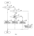
次に、ECU7のCPU21が実行する画像表示処理について、図7のフローチャートを用いて説明する。本処理は、自車両のアクセサリスイッチがオンである間、繰り返し実行される。
次に、ECU7のCPU21が実行する画像表示処理について、図7のフローチャートを用いて説明する。本処理は、自車両のアクセサリスイッチがオンである間、繰り返し実行される。
まずS1では、CPU21は、セレクタ31により設定されたシフトレンジがPレンジ又はNレンジであるか否かを判定する。このS1にてシフトレンジがPレンジ又はNレンジであると判定されれば、処理がS2に移行する。一方、Pレンジ及びNレンジでないと判定されれば、処理がS3に移行する。
S2では、CPU21は、車両後方に仮想視点を設定する。つまり、車両が停止している場合には、表示装置5に表示される周辺画像は、車両後方が仮想視点である上述した後方視点画像103となる。その後、本処理を終了する。
なお仮想視点が設定された後は、他の仮想視点に設定が変更されるまでは後方視点画像103が表示される。ここで、表示装置5に表示される後方視点画像103は、カメラ3により撮影された新たな撮影画像に基づいて更新される。即ち表示装置5には、車両後方の仮想視点から見た現在の状況を示す動画が表示されることとなる。このことは、後述するS5、S6、S7にて他の仮想視点に設定された場合も同様である。
S3では、CPU21は、シフトレンジがDレンジであるか否かを判定する。このS3にてシフトレンジがDレンジであると判定されれば、処理がS4に移行する。一方、Dレンジでないと判定されれば、つまりRレンジであると判定されれば、処理がS7に移行する。
S4では、CPU21は、車速が予め定められた一定値以下であるか否かを判定する。一定値以下の車速とは、例えば、15km/h~0km/hとすることができる。このS4にて車速が一定値以下であると判定されれば、処理がS5移行する。一方、車速が一定値以下でないと判定されれば、即ち車速が一定値を超えていると判定されれば、処理がS6に移行する。なお、この一定値の車速が、所定の速度に相当する。
S5では、CPU21は、車両前端上方に仮想視点を設定する。つまり、車両がゆっくりと前進している場合には、表示装置5に表示される周辺画像は、車両前端上方が仮想視点である上述した上方視点画像105となる。その後、本処理を終了する。
S6では、CPU21は、車両前方に仮想視点を設定する。つまり、車両が高速で前進している場合には、表示装置5に表示される周辺画像は、車両前方が仮想視点である上述した前方視点画像107となる。その後、本処理を終了する。
S7では、CPU21は、車両前方かつ上方に仮想視点を設定する。つまり、車両が後進している場合には、表示装置5に表示される周辺画像が、車両前方かつ上方が仮想視点である上述した前方俯瞰視点画像109となる。その後、本処理を終了する。
[1-4.効果]
以上詳述した実施形態によれば、以下の効果が得られる。
(1a)本実施形態の画像表示システム1では、セレクタ31の操作により設定されたシフトレンジと、車両の走行速度と、に基づいて、車両の走行状態に適した範囲を示す周辺画像が表示装置5に表示される。よって、車両の搭乗者は、その状況に応じた適切な画像を視認することができる。
以上詳述した実施形態によれば、以下の効果が得られる。
(1a)本実施形態の画像表示システム1では、セレクタ31の操作により設定されたシフトレンジと、車両の走行速度と、に基づいて、車両の走行状態に適した範囲を示す周辺画像が表示装置5に表示される。よって、車両の搭乗者は、その状況に応じた適切な画像を視認することができる。
(1b)上述した周辺画像は、カメラ3それぞれとは異なる視点の画像である。そのため、単にカメラ3それぞれの撮影画像から選択された画像が表示されるだけでなく、搭乗者が確認しやすい態様として表示させることができる。
(1c)上述した周辺画像には、カメラ3それぞれにて撮影された画像を合成して生成された画像が含まれる。このような周辺画像は、1つのカメラの撮影画像と比較して広い範囲を視認できるため、1つの周辺画像で多くの情報を搭乗者に与えることができる。
(1d)本実施形態では、シフトレンジがPレンジ又はNレンジである場合と、Dレンジ又はRレンジの場合と、において、異なる視点の周辺画像が表示装置5に表示される。そのため搭乗者は、エンジンの駆動力がタイヤに伝わる状態であるか否かを周辺画像から認識することができる。
また本実施形態では、シフトレンジがRレンジである場合と、それ以外の場合と、において、異なる視点の周辺画像が表示装置5に表示される。そのため、車両が後進する状態であることを搭乗者に認識させることができる。
[2.他の実施形態]
以上、本開示について説明したが、本開示は上述の実施形態に限定されることなく、種々変形することができる。
以上、本開示について説明したが、本開示は上述の実施形態に限定されることなく、種々変形することができる。
(2a)上記実施形態では、トランスミッション33の制御状態の判定を、車両の搭乗者によるセレクタ31の操作に基づいて行う構成を例示したが、これ以外の構成により判定を行う構成であってもよい。例えば、トランスミッションを制御する制御装置からトランスミッションの状態を示す信号を受信して判定してもよいし、車両が備えるトランスミッションがマニュアルトランスミッションである場合には、シフトレバーの位置に基づいて制御状態を判定してもよい。
また、搭乗者に代わって自動運転制御装置が一部又は全部の運転操作を実行する自動運転制御が行われる車両においては、自動運転制御装置から出力されるトランスミッションの制御状態を示す信号に基づいて、トランスミッションの制御状態を判定するように構成されていてもよい。
トランスミッションの制御状態は、そのときのギヤ比によって区分されるものであってもよい。
(2b)上記実施形態では、状態判定部25が、エンジンを走行駆動源とする車両について、その駆動力の出力方向を制御する出力制御装置であるトランスミッションの状態を判定する構成を例示した。しかしながら、走行駆動源及び出力制御装置は、上記実施形態の構成に限定されない。例えば走行駆動源としてモーターを用いる構成であってもよい。
(2b)上記実施形態では、状態判定部25が、エンジンを走行駆動源とする車両について、その駆動力の出力方向を制御する出力制御装置であるトランスミッションの状態を判定する構成を例示した。しかしながら、走行駆動源及び出力制御装置は、上記実施形態の構成に限定されない。例えば走行駆動源としてモーターを用いる構成であってもよい。
走行駆動源がモーターである場合には、モーターの回転方向を制御するモーター制御装置が出力制御装置に相当する。状態判定部25は、モーター制御装置の状態を、当該モーター制御装置から出力される信号に基づいて判定してもよいし、セレクタの操作位置から判定してもよい。もちろん走行駆動源がモーターであっても、トランスミッションを備えている場合には、トランスミッションの状態を判定するように構成されていてもよい。
(2c)上記実施形態では、車両には4つのカメラが搭載される構成を例示したが、その数は特に限定されず、5つ以上のカメラが設けられていてもよいし、3つ以下のカメラが設けられていても良い。
(2d)上記実施形態では、トランスミッションの制御状態と走行速度とに応じて、視点の異なる周辺画像が表示される構成を例示したが、視点に限らず、表示範囲が異なる画像が表示される構成であってもよい。例えば、シフトレンジがPレンジのときには車両を真下に見下ろす鳥瞰画像が表示され、シフトレンジがDレンジであり走行速度が一定値以下の場合には、その鳥瞰画像のうち車両前端周辺が拡大して表示される構成とすることが考えられる。
(2e)上記実施形態では、周辺画像としてカメラ3それぞれとは異なる視点の画像が生成されて表示装置5に表示される構成を例示したが、少なくとも1つの周辺画像がカメラ3のいずれかと同じ視点の画像であってもよい。その画像は、カメラ3により撮影された画像そのものであってもよいし、撮影された画像を画像処理することにより生成された画像であってもよい。
(2f)上記実施形態では、シフトレンジがDレンジの場合のみ、速度に応じて周辺画像が変化する構成を例示したが、シフトレンジがRレンジの場合においても速度に応じて周辺画像が変化する構成としてもよい。例えば、セレクタがRレンジとなっており、速度が3km/h以下の場合には後方視点画像103が表示されるが、速度が3km/hを超えた場合には前方俯瞰視点画像109が表示される構成とすることが考えられる。
また前進するためのシフトレンジとしてDレンジ以外のレンジが存在する場合は、それぞれのレンジ及び走行速度に応じた周辺画像を表示する構成としてもよい。
また、トランスミッションにおいて設定されているギヤ比と走行速度とに応じた周辺画像を表示する構成としてもよい。
また、トランスミッションにおいて設定されているギヤ比と走行速度とに応じた周辺画像を表示する構成としてもよい。
また、シフトレンジがPレンジの場合とNレンジの場合とで、異なる周辺画像を表示する構成としてもよい。
(2g)周辺画像の種類は上記実施形態に示したものに限定されず、また5種類以上であってもよい。例えば走行速度に応じて段階的に表示される周辺画像の視点や表示範囲が変化する構成であってもよい。
(2g)周辺画像の種類は上記実施形態に示したものに限定されず、また5種類以上であってもよい。例えば走行速度に応じて段階的に表示される周辺画像の視点や表示範囲が変化する構成であってもよい。
また、セレクタの操作や速度の変化に応じて表示される周辺画像が切り替わる場合において、切り替わる前の視点と切り替わった後の視点との間に位置する視点の画像を1つ以上表示することにより、表示装置5に表示される画像の視点が徐々に変化するように構成されていてもよい。
(2h)表示装置5には、複数の周辺画像が同時に表示される構成であってもよいし、1つ以上の周辺画像と、その他の画像と、が同時に表示される構成であってもよい。
(2i)上記各実施形態における1つの構成要素が有する機能を複数の構成要素に分担させたり、複数の構成要素が有する機能を1つの構成要素に発揮させたりしてもよい。また、複数の構成要素が有する複数の機能を、1つの構成要素によって実現したり、複数の構成要素によって実現される1つの機能を、1つの構成要素によって実現したりしてもよい。また、上記実施形態の構成の一部を省略してもよい。また、上記実施形態の構成の少なくとも一部を、他の上記実施形態の構成に対して付加又は置換してもよい。なお、特許請求の範囲に記載した文言のみによって特定される技術思想に含まれるあらゆる態様が本発明の実施形態である。
(2i)上記各実施形態における1つの構成要素が有する機能を複数の構成要素に分担させたり、複数の構成要素が有する機能を1つの構成要素に発揮させたりしてもよい。また、複数の構成要素が有する複数の機能を、1つの構成要素によって実現したり、複数の構成要素によって実現される1つの機能を、1つの構成要素によって実現したりしてもよい。また、上記実施形態の構成の一部を省略してもよい。また、上記実施形態の構成の少なくとも一部を、他の上記実施形態の構成に対して付加又は置換してもよい。なお、特許請求の範囲に記載した文言のみによって特定される技術思想に含まれるあらゆる態様が本発明の実施形態である。
(2j)上述した画像処理部19を備えるECU7に加え、当該ECU7を構成要素とする画像表示システム1、当該画像処理部19としてコンピュータを機能させるためのプログラム、このプログラムを記録した半導体メモリ等の非遷移的実態的記録媒体、画像表示方法など、種々の形態で本開示を実現することもできる。
Claims (7)
- 情報処理装置(7)であって、
車両の駆動力の出力方向を制御する出力制御装置(33)による制御状態を判定するように構成された状態判定部(25)と、
前記車両の走行速度を検出するように構成された速度検出部(26)と、
前記車両の周囲を撮影する1つ以上のカメラ(3a、3b、3c、3d)により撮影された画像に基づく前記車両の周辺を示す画像であって、それぞれ少なくとも視点及び表示範囲のいずれか一方が異なる画像である複数の周辺画像(103、105、107、109)の中から、前記状態判定部により判定された前記制御状態と、前記速度検出部により検出された前記走行速度と、に応じて定まる1つ以上の前記周辺画像を表示装置(5)に表示させるように構成された表示制御部(28)と、を備える、情報処理装置。 - 請求項1に記載の情報処理装置であって、
前記状態判定部は、前記車両の備えるセレクタ(31)により選択されるシフトレンジに基づいて前記制御状態を判定するように構成されている、情報処理装置。 - 請求項1又は請求項2に記載の情報処理装置であって、
さらに、前記1つ以上のカメラにより撮影された画像に基づいて、該画像とは少なくとも視点及び表示範囲のいずれか一方が異なる1つ以上の画像を生成するように構成された画像生成部(27)を備え、
前記複数の周辺画像は、前記画像生成部により生成された画像を含む、情報処理装置。 - 請求項1から請求項3のいずれか1項に記載の情報処理装置であって、
前記表示制御部は、前記状態判定部により判定される前記制御状態が、前記車両を前方に進行させるように駆動力を伝える状態である場合において、前記速度検出部が検出する速度が所定の速度以下であるときは、前記車両の前方の路面であって前記車両の運転者から死角となる領域を表示する前記周辺画像を前記表示装置に表示させ、前記速度検出部が検出する速度が前記所定の速度を超えるときは、前記車両の後方及び側方を表示する前記周辺画像を前記表示装置に表示させるように構成されている、情報処理装置。 - 請求項1から請求項4のいずれか1項に記載の情報処理装置であって、
前記表示制御部は、前記状態判定部により判定される前記制御状態が、前記駆動力の伝達を行わない状態である場合と、前記車両を前方又は後方に進行させるように駆動力を伝える状態である場合と、において、異なる視点の前記周辺画像を前記表示装置に表示させるように構成されている、情報処理装置。 - 請求項1から請求項5のいずれか1項に記載の情報処理装置であって、
前記表示制御部は、前記状態判定部により判定される前記制御状態が、前記車両を後方に進行させるように動力を伝える状態である場合と、それ以外の状態である場合と、において、異なる視点の前記周辺画像を前記表示装置に表示させるように構成されている、情報処理装置。 - コンピュータを、
車両の駆動力の出力方向を制御する出力制御装置(33)による制御状態を判定するように構成された状態判定部(25)と、
前記車両の走行速度を検出するように構成された速度検出部(26)と、
前記車両の周囲を撮影する1つ以上のカメラ(3a、3b、3c、3d)により撮影された画像に基づく前記車両の周辺を示す画像であって、それぞれ少なくとも視点及び表示範囲のいずれか一方が異なる画像である複数の周辺画像(103、105、107、109)の中から、前記状態判定部により判定された前記制御状態と、前記速度検出部により検出された前記走行速度と、に応じて定まる1つ以上の前記周辺画像を表示装置(5)に表示させるように構成された表示制御部(28)と、として機能させるプログラム。
Priority Applications (3)
| Application Number | Priority Date | Filing Date | Title |
|---|---|---|---|
| CN201780015616.8A CN108702491A (zh) | 2016-03-07 | 2017-03-06 | 信息处理装置以及程序 |
| DE112017001178.7T DE112017001178B4 (de) | 2016-03-07 | 2017-03-06 | Informationsverarbeitungsvorrichtung und -programm |
| US16/082,395 US10706292B2 (en) | 2016-03-07 | 2017-03-06 | Information processing apparatus and program |
Applications Claiming Priority (2)
| Application Number | Priority Date | Filing Date | Title |
|---|---|---|---|
| JP2016043469A JP6597415B2 (ja) | 2016-03-07 | 2016-03-07 | 情報処理装置及びプログラム |
| JP2016-043469 | 2016-03-07 |
Publications (1)
| Publication Number | Publication Date |
|---|---|
| WO2017154833A1 true WO2017154833A1 (ja) | 2017-09-14 |
Family
ID=59790218
Family Applications (1)
| Application Number | Title | Priority Date | Filing Date |
|---|---|---|---|
| PCT/JP2017/008771 Ceased WO2017154833A1 (ja) | 2016-03-07 | 2017-03-06 | 情報処理装置及びプログラム |
Country Status (5)
| Country | Link |
|---|---|
| US (1) | US10706292B2 (ja) |
| JP (1) | JP6597415B2 (ja) |
| CN (1) | CN108702491A (ja) |
| DE (1) | DE112017001178B4 (ja) |
| WO (1) | WO2017154833A1 (ja) |
Cited By (2)
| Publication number | Priority date | Publication date | Assignee | Title |
|---|---|---|---|---|
| CN110962598A (zh) * | 2018-09-28 | 2020-04-07 | 本田技研工业株式会社 | 车辆用信息显示装置 |
| EP3682320B1 (fr) * | 2017-09-15 | 2024-03-06 | Renault s.a.s | Procédé d'affichage sur un écran d'un environnement d'un véhicule automobile, et véhicule automobile dans lequel un tel procédé est mis en oeuvre |
Families Citing this family (6)
| Publication number | Priority date | Publication date | Assignee | Title |
|---|---|---|---|---|
| WO2019142660A1 (ja) * | 2018-01-19 | 2019-07-25 | ソニー株式会社 | 画像処理装置および画像処理方法、並びにプログラム |
| JP7160701B2 (ja) * | 2019-01-23 | 2022-10-25 | 株式会社小松製作所 | 作業機械のシステム及び方法 |
| JP7065068B2 (ja) * | 2019-12-13 | 2022-05-11 | 本田技研工業株式会社 | 車両周囲監視装置、車両、車両周囲監視方法およびプログラム |
| JP7398637B2 (ja) * | 2020-05-28 | 2023-12-15 | パナソニックIpマネジメント株式会社 | 表示制御装置、車両及び表示制御方法 |
| JP7429865B2 (ja) * | 2020-05-28 | 2024-02-09 | パナソニックIpマネジメント株式会社 | 表示制御装置、車両及び表示制御方法 |
| JP2023082954A (ja) * | 2021-12-03 | 2023-06-15 | 本田技研工業株式会社 | 制御装置、制御方法、及び制御プログラム |
Citations (4)
| Publication number | Priority date | Publication date | Assignee | Title |
|---|---|---|---|---|
| JP2002109697A (ja) * | 2000-10-02 | 2002-04-12 | Matsushita Electric Ind Co Ltd | 運転支援装置 |
| JP2011004201A (ja) * | 2009-06-19 | 2011-01-06 | Konica Minolta Opto Inc | 周辺表示装置 |
| JP2011091527A (ja) * | 2009-10-21 | 2011-05-06 | Panasonic Corp | 映像変換装置及び撮像装置 |
| WO2011158304A1 (ja) * | 2010-06-18 | 2011-12-22 | 三菱電機株式会社 | 運転支援装置、運転支援システム、および運転支援カメラユニット |
Family Cites Families (11)
| Publication number | Priority date | Publication date | Assignee | Title |
|---|---|---|---|---|
| JPH03286306A (ja) | 1990-04-03 | 1991-12-17 | Mitsubishi Electric Corp | 数値制御装置 |
| EP2267656A3 (en) | 1998-07-31 | 2012-09-26 | Panasonic Corporation | Image displaying apparatus und image displaying method |
| US7995095B2 (en) * | 2001-10-18 | 2011-08-09 | Autoliv Development Ab | Night vision device for a vehicle |
| AU2003225228A1 (en) * | 2002-05-03 | 2003-11-17 | Donnelly Corporation | Object detection system for vehicle |
| US8564079B2 (en) * | 2008-04-21 | 2013-10-22 | Qualcomm Incorporated | STT MRAM magnetic tunnel junction architecture and integration |
| JP5271154B2 (ja) | 2009-05-29 | 2013-08-21 | 富士通テン株式会社 | 画像生成装置及び画像表示システム |
| US8564657B2 (en) * | 2009-05-29 | 2013-10-22 | Honda Research Institute Europe Gmbh | Object motion detection system based on combining 3D warping techniques and a proper object motion detection |
| JP5152244B2 (ja) * | 2010-04-06 | 2013-02-27 | トヨタ自動車株式会社 | 追従対象車特定装置 |
| JP5206752B2 (ja) * | 2010-08-30 | 2013-06-12 | 株式会社デンソー | 走行環境認識装置 |
| JP2012195793A (ja) * | 2011-03-17 | 2012-10-11 | Clarion Co Ltd | 車両周辺監視装置 |
| JP5669791B2 (ja) * | 2012-08-07 | 2015-02-18 | 本田技研工業株式会社 | 移動体の周辺画像表示装置 |
-
2016
- 2016-03-07 JP JP2016043469A patent/JP6597415B2/ja active Active
-
2017
- 2017-03-06 CN CN201780015616.8A patent/CN108702491A/zh not_active Withdrawn
- 2017-03-06 DE DE112017001178.7T patent/DE112017001178B4/de active Active
- 2017-03-06 WO PCT/JP2017/008771 patent/WO2017154833A1/ja not_active Ceased
- 2017-03-06 US US16/082,395 patent/US10706292B2/en active Active
Patent Citations (4)
| Publication number | Priority date | Publication date | Assignee | Title |
|---|---|---|---|---|
| JP2002109697A (ja) * | 2000-10-02 | 2002-04-12 | Matsushita Electric Ind Co Ltd | 運転支援装置 |
| JP2011004201A (ja) * | 2009-06-19 | 2011-01-06 | Konica Minolta Opto Inc | 周辺表示装置 |
| JP2011091527A (ja) * | 2009-10-21 | 2011-05-06 | Panasonic Corp | 映像変換装置及び撮像装置 |
| WO2011158304A1 (ja) * | 2010-06-18 | 2011-12-22 | 三菱電機株式会社 | 運転支援装置、運転支援システム、および運転支援カメラユニット |
Cited By (3)
| Publication number | Priority date | Publication date | Assignee | Title |
|---|---|---|---|---|
| EP3682320B1 (fr) * | 2017-09-15 | 2024-03-06 | Renault s.a.s | Procédé d'affichage sur un écran d'un environnement d'un véhicule automobile, et véhicule automobile dans lequel un tel procédé est mis en oeuvre |
| CN110962598A (zh) * | 2018-09-28 | 2020-04-07 | 本田技研工业株式会社 | 车辆用信息显示装置 |
| US11511626B2 (en) | 2018-09-28 | 2022-11-29 | Honda Motor Co., Ltd. | Information display device for vehicle |
Also Published As
| Publication number | Publication date |
|---|---|
| JP2017163206A (ja) | 2017-09-14 |
| JP6597415B2 (ja) | 2019-10-30 |
| US20190087665A1 (en) | 2019-03-21 |
| DE112017001178B4 (de) | 2024-11-28 |
| CN108702491A (zh) | 2018-10-23 |
| DE112017001178T5 (de) | 2018-11-15 |
| US10706292B2 (en) | 2020-07-07 |
Similar Documents
| Publication | Publication Date | Title |
|---|---|---|
| JP6597415B2 (ja) | 情報処理装置及びプログラム | |
| CN102474597B (zh) | 车辆周围图像生成装置 | |
| US20200082185A1 (en) | Periphery monitoring device | |
| KR101266734B1 (ko) | 표시장치 | |
| US8854466B2 (en) | Rearward view assistance apparatus displaying cropped vehicle rearward image | |
| US9973734B2 (en) | Vehicle circumference monitoring apparatus | |
| CN108886602B (zh) | 信息处理装置 | |
| JP5953824B2 (ja) | 車両用後方視界支援装置及び車両用後方視界支援方法 | |
| JP7151293B2 (ja) | 車両周辺表示装置 | |
| US20100134264A1 (en) | Vehicle surrounding confirmation apparatus | |
| US20140036063A1 (en) | Around view monitor system and monitoring method | |
| US20170259831A1 (en) | Driving assistance device and driving assistance system | |
| WO2014068856A1 (ja) | 画像生成装置、および画像生成プログラム製品 | |
| JP7006460B2 (ja) | 車両用表示制御装置、車両用表示システム、車両用表示制御方法、およびプログラム | |
| JP7000383B2 (ja) | 画像処理装置および画像処理方法 | |
| JP2016049868A (ja) | 車両の制御装置 | |
| CN110895443A (zh) | 显示控制装置 | |
| CN109429042B (zh) | 一种周围视野监控系统及其盲点视野监控图像提供方法 | |
| US11669230B2 (en) | Display control device | |
| WO2015122124A1 (ja) | 車両周辺画像表示装置、車両周辺画像表示方法 | |
| JP2005186648A (ja) | 車両用周囲視認装置および表示制御装置 | |
| CN111095921A (zh) | 显示控制装置 | |
| CN110877574A (zh) | 显示控制装置 | |
| JP6876236B2 (ja) | 表示制御装置 | |
| JP2007221200A (ja) | 車両周辺監視装置 |
Legal Events
| Date | Code | Title | Description |
|---|---|---|---|
| 121 | Ep: the epo has been informed by wipo that ep was designated in this application |
Ref document number: 17763173 Country of ref document: EP Kind code of ref document: A1 |
|
| 122 | Ep: pct application non-entry in european phase |
Ref document number: 17763173 Country of ref document: EP Kind code of ref document: A1 |