WO2017154522A1 - 卓上切断機 - Google Patents
卓上切断機 Download PDFInfo
- Publication number
- WO2017154522A1 WO2017154522A1 PCT/JP2017/005913 JP2017005913W WO2017154522A1 WO 2017154522 A1 WO2017154522 A1 WO 2017154522A1 JP 2017005913 W JP2017005913 W JP 2017005913W WO 2017154522 A1 WO2017154522 A1 WO 2017154522A1
- Authority
- WO
- WIPO (PCT)
- Prior art keywords
- spindle
- bearing
- saw blade
- frame
- cutting machine
- Prior art date
- Legal status (The legal status is an assumption and is not a legal conclusion. Google has not performed a legal analysis and makes no representation as to the accuracy of the status listed.)
- Ceased
Links
Images





Classifications
-
- B—PERFORMING OPERATIONS; TRANSPORTING
- B23—MACHINE TOOLS; METAL-WORKING NOT OTHERWISE PROVIDED FOR
- B23D—PLANING; SLOTTING; SHEARING; BROACHING; SAWING; FILING; SCRAPING; LIKE OPERATIONS FOR WORKING METAL BY REMOVING MATERIAL, NOT OTHERWISE PROVIDED FOR
- B23D45/00—Sawing machines or sawing devices with circular saw blades or with friction saw discs
- B23D45/04—Sawing machines or sawing devices with circular saw blades or with friction saw discs with a circular saw blade or the stock carried by a pivoted lever
-
- B—PERFORMING OPERATIONS; TRANSPORTING
- B23—MACHINE TOOLS; METAL-WORKING NOT OTHERWISE PROVIDED FOR
- B23D—PLANING; SLOTTING; SHEARING; BROACHING; SAWING; FILING; SCRAPING; LIKE OPERATIONS FOR WORKING METAL BY REMOVING MATERIAL, NOT OTHERWISE PROVIDED FOR
- B23D45/00—Sawing machines or sawing devices with circular saw blades or with friction saw discs
- B23D45/14—Sawing machines or sawing devices with circular saw blades or with friction saw discs for cutting otherwise than in a plane perpendicular to the axis of the stock, e.g. for making a mitred cut
-
- B—PERFORMING OPERATIONS; TRANSPORTING
- B23—MACHINE TOOLS; METAL-WORKING NOT OTHERWISE PROVIDED FOR
- B23D—PLANING; SLOTTING; SHEARING; BROACHING; SAWING; FILING; SCRAPING; LIKE OPERATIONS FOR WORKING METAL BY REMOVING MATERIAL, NOT OTHERWISE PROVIDED FOR
- B23D47/00—Sawing machines or sawing devices working with circular saw blades, characterised only by constructional features of particular parts
- B23D47/12—Sawing machines or sawing devices working with circular saw blades, characterised only by constructional features of particular parts of drives for circular saw blades
-
- B—PERFORMING OPERATIONS; TRANSPORTING
- B27—WORKING OR PRESERVING WOOD OR SIMILAR MATERIAL; NAILING OR STAPLING MACHINES IN GENERAL
- B27B—SAWS FOR WOOD OR SIMILAR MATERIAL; COMPONENTS OR ACCESSORIES THEREFOR
- B27B5/00—Sawing machines working with circular or cylindrical saw blades; Components or equipment therefor
- B27B5/16—Saw benches
- B27B5/18—Saw benches with feedable circular saw blade, e.g. arranged on a carriage
- B27B5/20—Saw benches with feedable circular saw blade, e.g. arranged on a carriage the saw blade being adjustable according to depth or angle of cut; Radial saws, i.e. sawing machines with a pivoted radial arm for guiding the movable carriage
-
- B—PERFORMING OPERATIONS; TRANSPORTING
- B27—WORKING OR PRESERVING WOOD OR SIMILAR MATERIAL; NAILING OR STAPLING MACHINES IN GENERAL
- B27B—SAWS FOR WOOD OR SIMILAR MATERIAL; COMPONENTS OR ACCESSORIES THEREFOR
- B27B5/00—Sawing machines working with circular or cylindrical saw blades; Components or equipment therefor
- B27B5/29—Details; Component parts; Accessories
- B27B5/30—Details; Component parts; Accessories for mounting or securing saw blades or saw spindles
Definitions
- a general tabletop cutting machine uses wood as a material to be cut (work), a base portion on which the workpiece can be placed, a cutting portion having a circular saw blade for cutting the workpiece, a motor for rotationally driving the circular saw blade, A transmission mechanism that transmits rotational power from the motor to the circular saw blade.
- the operator performs the cutting operation by swinging the cutting portion of the tabletop cutting machine toward the workpiece.
- the fourth pulley is provided with a bearing between the saw blade and the fourth pulley, and a bearing is provided on the side opposite to the saw blade of the fourth pulley, so that the axial length of the spindle becomes long, Visibility and portability are deteriorated because the gear case is enlarged. Further, when cutting with the cutting portion inclined to the right side, the lower part of the case covering the spindle easily interferes with the workpiece, and the depth of cut into the workpiece cannot be increased.
- the present invention has been made in view of such problems, and its object is to realize a tabletop cutting machine in which the mounting portion of the spindle is downsized to improve visibility and portability. Is to realize a tabletop cutting machine having the same cutting performance when the cutting portion is inclined in the left-right direction. Another object of the present invention is to realize a tabletop cutting machine that can reduce spindle runout while achieving downsizing of the mounting portion of the spindle.
- the spindle is arranged in one side direction of the frame by two bearings having different diameters arranged so as to overlap in the axial direction. It was comprised so that it might be supported by.
- a cylindrical portion for holding the bearing is formed on the spindle, and the bearing is disposed on the inner side and the outer side of the cylindrical portion, respectively.
- the outer bearing is held between the inner wall portion of the cylindrical wall formed in the frame, and the inner bearing is held between a fixing member such as a pin arranged so as to extend from the frame in the axial direction of the spindle. Is done.
- This spindle does not penetrate the frame and is fixed in a cantilevered manner on one side as viewed in the thickness direction of the frame, so the size of the spindle holding part of the frame and the axial length can be made compact. Can be formed.
- a power transmission member formed with a belt portion or a gear is mounted on the spindle.
- the length of the power transmission member in the axial direction of the belt or gear is preferably arranged so as to overlap the axial length of the inner bearing and the outer bearing.
- a pulley is provided at the end of the intermediate rotating shaft near the circular saw blade, a pulley portion is formed on the power transmission member, and power is transmitted between the pulley and the pulley portion by the belt.
- a gear is provided at the end of the intermediate rotary shaft close to the circular saw blade, a gear is formed on the outer peripheral side of the power transmission member, and the gear and the gear portion are engaged to rotate the intermediate rotary shaft. Force may be transmitted to the spindle.
- an inclined support portion that supports the swing support portion so as to be tiltable in the left-right direction with respect to the base portion is provided, and the end of the spindle inner bearing away from the circular saw blade is provided.
- the position of the part was arranged so as to be closer to the circular saw than the position of the end part away from the circular saw blade of the outer bearing.
- the bearing that supports the spindle is a shell-type needle roller bearing, which is composed of an outer ring formed by drawing a thin steel plate, a plurality of needle rollers disposed inside the outer ring, and a cage for guiding the needle rollers. Therefore, the space required in the radial direction is small, and a very compact spindle holding structure can be realized.
- FIG. 2 is a cross-sectional view taken along a line AA in FIG. It is the perspective view seen from the diagonal left side of the flame
- FIG. 3 is a development view for explaining a structure for attaching a spindle 33 to a single frame 10 of FIG. 2.
- FIG. 3 is an enlarged cross-sectional view of a spindle unit 30 in FIG. 2. It is a figure for demonstrating the examination process until it reaches the structure of the spindle part 30 of a present Example.
- the operator can tilt the tilting portion 116 leftward or rightward with the tilting shaft 140 as a fulcrum.
- the tilting portion 116 is fixed at an arbitrary tilting position. it can.
- the tilting part 116 can tilt in the left-right direction, so that the entire cutting part 2 including the motor 5 held by the tilting part 116 can be tilted to the right or left, and the saw blade 60 is placed on the upper surface of the workpiece W.
- the sliding part 120 is slidable in the front-rear direction by being slidably held by the two guide bars 145 fixed to the tilting part 116.
- a swing support portion (support portion) 124 that supports the cutting portion 2 so as to be swingable in a substantially vertical direction is provided on the lower pedestal portion of the slide portion 120.
- the swing support portion 124 has a swing shaft 122, and the cutting portion 2 can be rotated clockwise from the state of FIG. This rotation is performed by the operator holding the handle 7 and pushing it downward.
- the swing support portion 124 is provided with a torsion (torsion) spring (not shown). The torsion spring biases the cutting portion 2 counterclockwise, and the cutting portion 2 is maintained in the state shown in FIG. .
- the cutting unit 2 mainly includes a saw blade (circular saw blade) 60 that rotates, a motor 5, a transmission mechanism that transmits the rotational power from the motor 5 to the saw blade 60, and a frame that holds these (see FIG. 2 to FIG. 2). 5) and a cover 9 that covers them.
- a motor cover 57 is attached to the rear upper part of the cover 9, and the motor 5 is housed inside the motor cover 57.
- a handle 7 that is gripped by an operator is formed on the front upper part of the cover 9, and a switch 8 that drives the motor 5 is provided on a part of the handle 7.
- a stopper bolt 147 is provided near the lower side of the cover 9. The stopper bolt 147 is fixed at a position facing the upper surface of the front end portion of the sliding portion 120.
- the stopper bolt 147 contacts the rear surface (contact surface 121) of the swing support portion 124 of the sliding portion 120, so that the cutting portion 2 swings downward.
- a dynamic limit position is defined.
- An LED light 111 attached to a flexible arm is provided above the cutting unit 2.
- the rotational force of the motor 5 is transmitted to the spindle 33 via the two V belts 22 and 42. Normally, the V belts 22 and 42 are not visible because they are inside the cover 9, but in FIG. 1, they are expressed so that the positional relationship can be easily understood.
- a protective cover 61 that moves when the cutting portion 2 is lowered is provided around the rear and lower sides of the saw blade 60.
- the intermediate rotating shaft 24 is disposed so as to penetrate from the one surface side of the frame 10 to the other surface side, and is supported near the center in the axial direction by two bearings 26 and 27 disposed side by side.
- a third pulley 25 is provided at the end opposite to the one end where the second pulley provided on the intermediate rotating shaft 24 is provided.
- the third pulley 25 is disposed between the frame 10 and the saw blade 60, and the rotation surface of the third pulley 25 is disposed so as to be parallel to the rotation surface of the saw blade 60.
- the rotational force of the third pulley 25 is transmitted to the fourth pulley 41 provided coaxially with the spindle 33 via the V belt 42.
- the V belt 22 and the V belt 42 are generated by an elastic body such as resin or rubber.
- the spindle 33 is disposed on the saw blade side from the center position in the thickness direction of the frame 10 and is supported in a so-called cantilever manner. For this reason, the spindle 33 is positioned on one side (left side) of the center line in the thickness direction of the frame 10 (a line passing through the center in the thickness direction near the arrow 10a).
- the entire length of the spindle 33 is short from the viewpoint of workability (visibility and portability), and the thickness direction of the frame 10 from the saw blade 60 is reduced. A shorter distance S to the center position is better.
- FIG. 3 is a perspective view of the frame 10 alone as seen from the oblique left side.
- the frame 10 is manufactured by integral molding of an aluminum alloy, and is mainly configured by an arm portion 17 extending from the swing shaft, a motor attachment portion 11 connected to the arm portion 17, and a saw blade attachment portion 12 extending on a side surface of the saw blade 60. Is done.
- the arm portion 17 is an aluminum alloy integrated block, and on the lower side thereof, mounting bases 17a and 17b for pivotally supporting the swing shaft 122 (see FIG. 1) are formed. Through-holes 18a and 18b are formed for penetrating them.
- the motor mounting portion 11 on the upper rear side of the arm portion 17 is a portion that holds the motor 5 that is a driving source for rotating the saw blade 60, and is formed with a cylindrical portion 11 b corresponding to the outer diameter of the motor 5.
- a flange portion for fixing a motor cover 57 that houses the motor 5 is provided outside the portion 11b.
- Three screw holes 11d are formed in the flange portion. Inside the cylindrical portion 11b, a through hole is formed to allow the rotation shaft 51 of the motor 5 to pass therethrough and a cylindrical portion 11a for holding the bearing 54 is formed. Air is passed through the outer peripheral side of the cylindrical portion 11a.
- a plurality of wind windows 11c are formed. The wind window 11 c also serves to reduce the weight of the cutting part 2 by reducing the thickness of the frame 10.
- a saw blade mounting portion 12 is formed on the upper front side of the arm portion 17.
- the saw blade mounting portion 12 is formed of a single piece of metal such as an aluminum alloy, and the main portion is formed by machining.
- the saw blade mounting portion 12 is formed with a flat surface portion 12a that covers the right side surface of the rear half of the saw blade 60 and an outer peripheral surface 12b that projects the outer edge of the flat surface portion 12a toward the saw blade side.
- Mounting ribs 13a and 13b in which screw holes for fixing the cover 9 (see FIG. 1) are formed are formed outside the outer peripheral surface 12b.
- a substantially oval wall portion 14 is formed in the left side view covering the outer periphery of the third pulley 25 and the fourth pulley 41 protruding leftward from the flat surface portion 12a.
- the A V-belt 42 (not shown) travels in the inner portion of the wall portion 14, but the wall portion 14 has a function of suppressing intrusion of dust such as chips around the third pulley 25 and the fourth pulley 41.
- the spindle 33 for fixing the saw blade 60 is formed with a flat portion 33a in which two opposing portions of the outer periphery of the cylinder are cut into a flat shape.
- FIG. 4 is a perspective view of the frame 10 alone shown in FIG. Near the center of the right side surface of the plane portion 12a of the frame 10, a second pulley 23 supported by the intermediate rotating shaft 24 is held.
- the portion that supports the intermediate rotating shaft 24 is formed with a cylindrical support cylindrical portion 19 whose center is recessed in order to support the bearings 26 and 27, and a thick wall is formed on the rear side thereof.
- a thick portion 15 is formed.
- the thick portion 15 is formed to increase the partial rigidity of the frame 10 in order to maintain the rotational accuracy of the intermediate rotating shaft 24 and the spindle 33.
- a slope portion 15a is formed such that the corners of the rear wall and the right side wall are cut off obliquely.
- the inclined surface portion 15a is formed to ensure the cutting depth of the right inclined cutting (described later in FIG. 8) by the saw blade 60 when the cutting portion 2 is tilted to the maximum (right side) where the spindle 33 is located. It is.
- a through hole 15b is formed near the rear end of the thick portion 15, and a pin 31 is press-fitted there.
- a shaft cover 17c that covers the periphery of the swing shaft 122 is provided between the mounting bases 17a and 17b.
- the bearings 32 and 34 are needle bearings (needle roller bearings), and a plurality of metal needles (needle rollers) are held in the circumferential direction inside a shell (cylindrical ring).
- the plurality of needles arranged on the inner periphery of the bearing 32 come into contact with the outer peripheral surface of the cylindrical metal pin 31 that is held through the frame 10, and the bearing 32 is held by the frame 10.
- the pin 31 is fixed to the through hole 15b formed in the frame 10 by press fitting, and acts as a fixing member of the bearing 32, and the pin 31 itself does not rotate.
- FIG. 6 is an enlarged cross-sectional view of the spindle portion 30 of FIG.
- the upper side of the center of rotation of the spindle 33 is a cross section parallel to the longitudinal direction of the V-belt 42, and the lower side of the center of rotation of the spindle 33 in the figure is the center of rotation, the screw 36 and the plane portion. Note that this is a cross-sectional view at a position passing through 33a.
- the spindle 33 is pivotally supported so that about half of the axial direction is accommodated in the support cylindrical portion 16 opened to the left side (the saw blade 60 side) of the thick portion 15 of the frame 10.
- the spindle 33 is a member in which a cylindrical bearing mounting portion penetrating in the axial direction is formed, and radially outward at an end portion (right end portion) near the bottom surface 16a of the support cylindrical portion 16.
- a large flange portion 33e is formed, and the bearing 34 disposed on the outer peripheral side of the spindle 33 is held so as not to be displaced to the frame side (right side) when viewed in the axial direction.
- a step portion 33d is formed on the inner peripheral side of the spindle 33, and the inner diameter on the side close to the frame 10 side (right side) is large in the axial direction, and the inner diameter on the saw blade 60 side (left side) is small. .
- the stepped portion 33d prevents the bearing 34 disposed on the inner peripheral side of the spindle 33 from moving to the saw blade 60 side (left side), and the bearing structure can be maintained.
- a metal pin 31 whose outer peripheral surface is ground is disposed on the inner peripheral side of the bearing 32. Since the outer peripheral surface of the pin 31 is used as a raceway surface of the bearing 32, the inner ring of the bearing 32 can be omitted.
- the pin 31 is fixed to the through hole 15b of the frame 10 by press fitting. In this way, the spindle 33 is attached to the support cylindrical portion 16 of the frame 10, and then a holding ring 35 is attached to prevent the bearing 34 from coming off in the axial direction, and is fixed with three screws 36. Is done.
- the spindle 33 is prevented from moving toward the saw blade 60 in the axial direction.
- the flange portion 33e of the spindle 33 abuts against the bottom surface 16a of the support cylindrical portion 16, so that further movement is prevented.
- a metal ring 45 having a low surface sliding resistance is attached to the bottom surface 16a.
- the fourth pulley 41 has an annular fixed surface 41 d that holds one surface of the saw blade 60, and the saw blade 60 is fastened together with the fixing washer 37 by the mounting bolt 38.
- An internal thread 33 b that is screwed with the thread of the mounting bolt 38 is formed on the inside of the spindle 33 on the saw blade 60 side.
- the mounting bolt 38 is a countersunk hexagonal bolt, and when it is mounted, it is important that the mounting bolt 38 has such a length as to have a gap 39 at the tip thereof and does not contact the pin 31. In this way, the spindle 33 is so-called cantilevered with respect to the frame 10.
- the bearings 32, 34 and the portion of the V-belt 42 occupying in the axial direction are in a positional relationship such that they partially overlap each other. For this reason, the distance (distance S + L in FIG. 2) from the saw blade 60 to the right end surface of the frame 10 as seen on the axis of the spindle 33 could be formed short.
- the bearing 34 is disposed closer to the saw blade 60 (left side) than the bearing 32 pivotally supported from the inside of the spindle 33.
- the intermediate rotating shaft 24 is arranged in parallel with the spindle 33 and can be rotated by a bearing 26 that supports the side away from the saw blade 60 and a bearing 27 that is positioned approximately in the middle of the thickness portion 15 of the thick portion 15 of the frame 10. Supported. Since the second pulley 23 and the third pulley 25 fixed to the intermediate rotating shaft 24 are held on the opposite sides of the frame 10, the rigidity of the intermediate rotating shaft 24 is strongly and stably held.
- the spindle 33 having a shape close to a cantilever support is disposed so that the portion occupied in the axial direction, that is, the position occupied in the axial direction of the bearings 32 and 34 partially overlaps the position occupied in the axial direction of the bearing 27. Is done.
- a lock mechanism (not shown) for locking the rotation of the spindle 33 may be provided when the saw blade 60 is attached to or removed from the tabletop cutting machine 1.
- the spindle 350 holding the saw blade 60 is pivotally supported by two bearings 351a and 351b.
- a fourth gear 352 that can rotate the spindle 350 meshes with a third gear 348 provided at the left end of the second intermediate rotation shaft 345.
- the second intermediate rotation shaft 345 is supported by two bearings 346a and 346b, and a second gear 347 is disposed between the bearings 346a and 346b.
- the first intermediate rotation shaft 333 is supported by bearings 334a and 334b, and a first gear 335 that meshes with the second gear 347 is provided between the bearings 334a and 334b. All the bearings used here are ball bearings.
- a second pulley 332 is provided at the right end of the first intermediate rotating shaft 333 and is driven by a V-belt 331 that is driven by the rotational force of a motor (not shown).
- FIG. 7 illustrates the process of improving the spindle holding structure of FIG.
- (3) is the spindle holding structure of the present embodiment
- (1) and (2) are structures considered up to the structure of (3).
- FIG. 7A shows a configuration in which the spindle 165 is cantilevered by two bearings 166 and 167 with respect to the frame 160.
- “cantilever support” is intended to be supported on the frame 160 (170, 10) by a bearing provided only on one side when viewed from the fourth pulley 169 that transmits power to the spindle 165.
- the bearing 167 is arranged on the outer peripheral side of the spindle 165.
- the shape of the portion near the frame 160 becomes larger, and the inclination is inclined to the right side. Disadvantageous when disconnected. Therefore, a small diameter bearing 166 is used.
- the shaft diameter of the spindle 165 is formed so as to correspond to the bearing 166. If formed in this way, the slope 160a can be formed on the lower side of the frame 160.
- the axial length B 3 occupied by the axial length B 4 and the bearing 166 occupied by the bearings 167 do not overlap in the axial direction.
- the fourth pulley 169 protrudes further left than the bearing 167, since the axial length B 4 occupied by the part and the bearing 167 of the belt V 2 do not overlap, it becomes thicker total thickness E by End up.
- the thickness F is reduced by arranging two bearings so as to overlap in the axial direction.
- the spindle 175 is formed in a cylindrical shape and the bearing 177 is arranged outside the cylindrical shape, but the spindle 175 is not protruded to the right side of the bearing 177 but the spindle. 175 inside.
- the outer peripheral side of the bearing 176 becomes the rotation side, so that the inner peripheral side must be a fixed end. Therefore, the bearing 176 is pivotally supported by using a pin 171 extending from the frame 170.
- the axial length of the spindle 175 can be shortened by the amount of the arrow 188.
- it was possible to shorten the axial length B 43 occupied by the axial length and the bearing 176 occupied by the bearings 177 it could be realized holding structure compact spindle.
- FIG. 7 (3) shows the shape of this embodiment.
- the traveling position of the V-belt 42 is further improved. Since the axial length B 43 occupied by the bearing 32 and the bearing 34 overlaps the axial length V 2 occupied by the V-belt 42, the portion indicated by the arrow 189 can be further reduced. Further, the length B 43 slightly overlaps with the axial length B 2 occupied by the bearing 27. In this way, the small-diameter bearing 32 (needle bearing) is offset away from the saw blade 60 rather than the large-diameter bearing (needle bearing) 34, and the small-diameter and large-diameter bearings 32 and 34 overlap in the axial direction.
- the length of the spindle 33 can be further shortened, and a highly rigid spindle holding structure can be realized even if it is a cantilever support type. Further, since the length B 43 and the length B 2 are arranged so as to slightly overlap, it is possible to further increase the rotational accuracy of the intermediate rotating shaft 24 and the spindle 33.
- the cutting ability of the tabletop cutting machine 1 having the tiltable cutting part 2 is greatly related to the depth of cutting into the workpiece W when the cutting part 2 is tilted.
- the part of the cutting part 2 excluding the saw blade 60 closest to the workpiece W is the V-belt 42, and the cutting depth at that time is T in FIG.
- the part of the cutting part 2 excluding the saw blade 60 closest to the workpiece W is the farthest away from the lower surface of the cover 9 in the vertical direction of the saw blade 60.
- a corner portion 9a, a slope portion 15a of the thick portion 15, and a corner portion 41e of the fourth pulley are related to the diagonal cutting depth to the workpiece W.
- the degree of freedom of design change is higher than that using gears.
- the V belt 42 is lengthened (the interval between the intermediate rotating shaft 24 and the spindle 33 is lengthened).
- the protrusion of the cover 9 downward from the spindle 33 can be suppressed.
- the spindle 33 is pivotally supported so as to be close to a so-called cantilever type, so that the protruding portion on the second pulley 23 side from the center line of the frame 10 (see FIG. 2).
- the size could be made extremely small.
- the transmission mechanism portion can be accommodated in a size range equivalent to the region occupied by the cooling fan 56 from one end of the rotating shaft 51.
- the cut portion 2 is reduced, and the portability and visibility associated with downsizing can be realized.
- the transmission mechanism can be made smaller and the position of the saw blade 60 can be shifted to the right side.
- the cutting portion 2 is inclined to the right side.
- the cutting depth B can be sufficiently secured even with the saw blade 60 having a relatively small diameter.
- it is not necessary to increase the diameter of the saw blade 60 in order to increase the cutting depth B at the time of inclined cutting as compared with the prior art it is not necessary to increase the length of the frame 10 in the cutting direction. 1 can also be made compact.
- the transmission mechanism for transmitting the rotation of the motor 5 to the saw blade 60 is constituted by a pulley and a belt and no gear is used, no noise is generated due to the meshing of the gear when the tabletop cutting machine 1 is operated, and it is silent. Excellent in properties.
- the second pulley 23 is arranged farther from the saw blade 60 than the third pulley 25 and the fourth pulley 41, that is, the V belt 42 is arranged on the saw blade 60 side from the V belt 22. For this reason, in the inclined state shown in FIG. 8, the V-belt 42 (fourth pulley 41) does not interfere with the inclination, so that the depth of cut B during the inclination can be increased.
- the cutting portion 202 includes a frame 215 that is pivotally supported by the swing shaft portion and a housing 257 that is an outer shell thereof.
- the frame 215 supports a spindle 233 that rotatably supports the saw blade 60 at the center axis position of the saw blade 60 in a cantilever manner.
- the motor 205 is arranged such that the rotation shaft extends in a direction parallel to the rotation surface of the saw blade 60, and the rotational force is transmitted to the first gear 252 and the second gear 261 by the pinion 251 at the tip of the rotation shaft.
- a cooling fan 256 is provided between the motor 205 and the pinion 251 and rotates in synchronization with the motor 205.
- the second gear 261 is provided at the upper end of the rotary shaft 260 extending long, and the first roller 264 is provided at a lower end of the rotary shaft 260 and adjacent to the side surface of the saw blade.
- the rotating shaft 260 is rotatably supported by two bearings 262 and 263.
- a further rotation axis 270 is provided in parallel with the rotation axis 260.
- the rotating shaft 270 is supported by the movable cover 280 by two bearings 272 and 273.
- the rotation shaft 270 is a driven rotation shaft, and the second roller 274 provided at the lower end sandwiches the saw blade 60 together with the first roller 264, whereby the saw blade 60 is rotated by the frictional force of the rotating first roller 264. I did it. Therefore, a compression spring 282 is provided on the upper portion of the movable cover 280, and the second roller 274 is configured to apply a predetermined urging force to the saw blade 60.
- the movable cover 280 on which the rotating shaft 270 is supported can be rotated about 90 degrees clockwise around the rotating shaft 281 to separate the second roller 274 from the saw blade 60. When the saw blade 60 is mounted or removed, the movable cover 280 is opened.
- a cylindrical portion 216 is formed at a portion of the frame 215 where the spindle 233 is attached.
- the cylindrical portion 216, the outer bearing 234, the spindle 233, and the inner bearing 232 may have substantially the same shape as the support cylindrical portion 16, the bearing 34, and the bearing 32 shown in FIG.
- a structural member corresponding to the fourth pulley 41 shown in FIG. 6 is a holding member 241 that has no pulley mechanism and only fixes the saw blade 60. Therefore, the axial length of the holding member 241 and the axial length of the spindle 233 can be configured shorter than the fourth pulley 41 and the spindle 33 shown in FIG.
- the arrangement method of the motor 205 is different from the first and second embodiments, and the power transmission path from the motor 205 to the saw blade 60 is completely different.
- the spindle 233 is axially supported by two bearings (232, 234) having different diameters arranged so as to overlap in the axial direction, the spindle holding is very compact as in the other embodiments.
- the structure was realized. In this way, the spindle 233 is formed with a cylindrical portion, and bearings (232, 234) are arranged inside and outside the cylindrical portion, respectively, and the outer bearing 234 is in contact with the inner wall portion of the cylindrical portion 216 formed on the frame 215.
- the inner bearing 232 is held by a metal pin 231 disposed so as to extend from the frame 215 in the axial direction of the spindle 233, a spindle holding structure that has high rigidity and can rotate smoothly can be realized. It was. Also in the third embodiment, it is possible to increase the cutting depth B when cutting by tilting to the right side, and the amount of tilting when tilting to the left side can be made substantially the same.
- one of the two power transmission belts is a V-belt
- the V-belt slips on the pulley when the saw blade engages with wood or the like, and the power transmission member is damaged. Can be suppressed.
- the tabletop cutting machine of the present invention can be widely used for cutting tools, grinding tools, and the like that require rotating cutting blades, and can also be applied to portable circular saws, for example.
- the bearing structure of the present invention can be applied to the rotating shaft in the transmission mechanism section to realize a small frame, and the two bearings that support the intermediate rotating shaft can be overlapped in the axial direction. Is also possible.
Landscapes
- Engineering & Computer Science (AREA)
- Mechanical Engineering (AREA)
- Life Sciences & Earth Sciences (AREA)
- Wood Science & Technology (AREA)
- Forests & Forestry (AREA)
- Sawing (AREA)
Abstract
スピンドルの取付部を小型化して卓上切断機の左右方向に傾斜させたときの切断性能を向上させる。鋸刃60を保持するスピンドル33を円筒形に形成し、円筒形の内側と外側にそれぞれ軸受32と34を配置してフレーム15に対して片持ち支持させるようにした。外側の軸受34はフレーム15に形成された円筒壁16の内壁部分との間に保持し、内側の軸受32はフレーム15からスピンドル33の軸方向に延びるように圧入される金属製のピン31にて固定する。スピンドル33を回転させる第四プーリ41は、Vベルト42の軸方向位置が、軸受32、34の軸方向位置と部分的にオーバーラップするように配置される。
Description
本発明は卓上切断機に関し、特に鋸刃が固定されるスピンドルの取付構造の改良に関するものである。
一般的な卓上切断機は木材を被切断材(ワーク)とし、ワークを載置可能なベース部と、ワークを切削する丸鋸刃を備える切断部と、丸鋸刃を回転駆動させるモータと、モータから丸鋸刃へと回転動力を伝達する伝達機構部と、を備える。作業者は、卓上切断機の切断部をワーク側へ揺動させることによって切削作業を行う。また、近年の卓上切断機では、切断部を鉛直面に対して右側又は左側に所望の角度で傾斜させた状態で揺動させることにより、ワークを載置面に対し斜めに切断することを可能である。例えば、特許文献1に開示された卓上切断機は、鋸刃に垂直に配置されたモータと、モータから出力された回転動力をプーリ間に架け渡されたベルト及びギヤによって鋸刃に伝達する伝達機構部とを備え、ベース部に載置されたワークに垂直な面に対し切断部を傾斜させることで、ワークを斜めに切断可能な機能を有する。
従来の卓上切断機の構造では、モータに取り付けられる第一プーリと、中間回転軸に取り付けられる第二プーリにVベルトを介して動力を伝達し、中間回転軸に設けられる第三プーリから鋸刃側のスピンドルに取り付けられる第四プーリにVベルトを介して動力を伝達した。ここで、モータの回転を大きく減速してスピンドルに伝達させるために、第一プーリと第四プーリを大きく形成する必要があるが、第四プーリを大きくしてしまうと鋸刃近傍のギヤケース部分が大型化してしまう。そこで、第二プーリを大きくして第四プーリを小さくするようにしつつ、スピンドルを軸支する軸受を軸方向に2つ設けて、スピンドルの剛性を高めるようにしていた。しかしながら、第四プーリは、鋸刃と第四プーリの間に軸受が設けられ、第四プーリの鋸刃と反対側に軸受が設けられるので、スピンドルの軸方向の長さが長くなってしまい、ギヤケースが大型化して視認性や可搬性が悪化してしまう。また、切断部を右側に傾斜させた状態で切削を行う際には、スピンドルを覆うケースの下部がワークに干渉し易くなり、ワークへの切込深さを深くすることができなかった。
厚みのあるワークを斜めに切削する際には、切断深さを確保するために大径の鋸刃を用いなければならない。しかしながら、大径の鋸刃を用いるには卓上切断機自体も大きくしなければならないので、収納性、可搬性が悪化し、更に体積が増えることで重量が増加してしまう。そこで左右の両方向に傾斜可能な卓上切断機において、右傾斜、左傾斜における切断可能な被切断材の厚さ、いわゆる切断能力を同等にすることは製品スペックの向上を図る上で重要である。
本発明はかかる問題点に鑑みてなされたものであり、その目的はスピンドルの取付部を小型化して視認性や可搬性を向上させた卓上切断機を実現することにある本発明の他の目的は、切断部を左右方向に傾斜させたときの切断性能を同等程度にした卓上切断機を実現することにある。本発明の他の目的は、スピンドルの取付け部分の小型化を達成しつつ、スピンドルの振れを低減することができる卓上切断機を実現することにある。
本願において開示される発明のうち代表的なものの特徴を説明すれば次の通りである。本発明の一つの特徴によれば、モータと、モータによって回転されるスピンドルと、スピンドルに固定される丸鋸刃を有する切断部と、被切断材を載置可能なベース部と、切断部をベース部に対して移動可能に保持する揺動支持部とを有する卓上切断機であって、切断部は、丸鋸刃の切断面と直交する方向に丸鋸刃を回転可能に保持するスピンドルと、モータからの動力をスピンドルへ伝達する動力伝達機構と、スピンドルを軸支するフレームを有し、スピンドルは、軸方向にオーバーラップさせるように配置された径が異なる2つの軸受によってフレームの片側方向に軸支されるように構成した。スピンドルには軸受を保持する円筒部が形成され、円筒部の内側と外側にそれぞれ軸受が配置される。ここで外側の軸受はフレームに形成された円筒壁の内壁部分との間に保持され、内側の軸受はフレームからスピンドルの軸方向に延びるように配置されるピン等の固定部材との間に保持される。このスピンドルはフレームを貫通すること無く、フレームの厚み方向にみて片側の面側に片持ち式に固定されるので、フレームのスピンドル保持部分の径方向の大きさや、軸方向の長さをコンパクトに形成できる。
本発明の他の特徴によれば、動力伝達機構はモータによって駆動されるものであってスピンドルと平行に配置される中間回転軸を有し、中間回転軸は2つの軸受によりフレームに軸支される。そして、スピンドルを保持する2つの軸受の占める全体の軸方向の長さ部分と、中間回転軸を保持する2つの軸受のうち一つの軸受の占める軸方向の長さ部分がオーバーラップするように配置した。このようにスピンドルと中間回転軸の配置において互いの軸受け部分が軸方向にオーバーラップするように保持したので、剛性を高めてスムーズな動力伝達が実現できる。スピンドルはベルト又はギヤによって中間回転軸の回転力がスピンドルに伝達される。スピンドルにはベルト部又はギヤが形成された動力伝達部材が装着される。動力伝達部材のベルト又はギヤの軸方向に占める長さ部分は、内側の軸受及び外側の軸受の占める軸方向の長さ部分とオーバーラップするように配置すると好ましい。中間回転軸の丸鋸刃に近い端部にプーリが設けられ、動力伝達部材にプーリ部が形成され、プーリとプーリ部との間がベルトによって動力伝達される。尚、プーリとベルトの代わりに、中間回転軸の丸鋸刃に近い端部にギヤを設け、動力伝達部材の外周側にギヤを形成し、ギヤとギヤ部が噛み合うことによって中間回転軸の回転力がスピンドルに伝達されるようにしても良い。
本発明のさらに他の特徴によれば、揺動支持部をベース部に対して左右方向に傾斜可能なように支持する傾斜支持部を設け、スピンドルの内側の軸受の丸鋸刃から離れた端部の位置を、外側の軸受の丸鋸刃から離れた端部の位置よりも丸鋸に近づくように配置した。また、フレームに形成された円筒壁の取り付け部分の被切断材に近い部分に、丸鋸をスピンドルが位置する側に最大傾斜させた際に被切断材との距離を確保するための斜面部を形成した。スピンドルを軸支する軸受はシェル形針状ころ軸受であって、薄い鋼板を絞り加工した外輪と、その内側に配置された複数の針状ころと、針状ころを案内する保持器により構成されるので、径方向に要するスペースが少なくて済み、大変コンパクトなスピンドルの保持構造を実現できる。
本発明によれば、スピンドルの取り付け構造を小型化できるので、ギヤケースを小型化して作業性能を向上できる。 本発明の上記及び他の目的ならびに新規な特徴は、以下の明細書の記載及び図面から明らかになるであろう。
以下、本発明の実施例を図面に基づいて説明する。なお、以下の図において、同一の部分には同一の符号を付し、繰り返しの説明は省略する。また、本明細書においては、前後左右、上下の方向は作業者が操作位置から見る方向を基準とし、図中に示す方向であるとして説明する。
図1は卓上切断機1の全体構成を示す側面図である。卓上切断機1は、主に、切断部2と、ベース112及びターンテーブル114により構成されるベース部と、切断部2を左右方向に傾斜可能にする傾動部(傾斜部)116と、切断部2を前後方向に移動可能にする摺動部120と、モータ5を含んで構成される。ベース112は木材等のワークWを担持するものであって、窪みが上面中央に形成された凹型の形状である。ベース112の上面には、ワークWの側面に当接するフェンス115が設置される。
ターンテーブル114は金属製であり、ベース112の垂直軸(図示せず)を中心に水平面で回動可能に支持され、ベース112の上面と同一平面上に上面が位置するように配設される。ターンテーブル114の後方側には回動操作部113が突出して配設され、回動操作部113を操作することによってターンテーブル114を回動させることができる。傾動部116は、ターンテーブル114の後端の傾斜支持部143に傾動軸140を介して左右方向に傾動可能なように支持される部分である。作業者はクランプ142を緩めることにより傾動軸140を支点として、傾動部116を左方向又は右方向に傾斜させることができ、クランプ142を締め付けることにより、傾動部116を任意の傾斜位置にて固定できる。このように傾動部116が左右方向に傾斜可能により、傾動部116により保持されるモータ5を含む切断部2の全体を右又は左に傾斜させることができ、鋸刃60をワークWの上面に対して所定の角度を隔てるようにして斜めに切断(傾斜切断)することが可能となる。
摺動部120は、傾動部116に固定された2本のガイドバー145に摺動可能に保持されることにより、前後方向に摺動可能となる。摺動部120の下側の台座部分には切断部2を略上下方向に揺動可能に支持する揺動支持部(支持部)124が設けられる。揺動支持部124は揺動軸122を有し、揺動軸122を介して切断部2を図1の状態から時計回りに回動可能にする。この回動は作業者がハンドル7を把持して下方向に押すことにより行う。揺動支持部124は内部に図示しないトーション(ねじり)ばねが配設されており、トーションばねは切断部2を反時計回りに付勢して切断部2は図1の状態にて維持される。
切断部2は、主に回転する鋸刃(丸鋸刃)60と、モータ5と、モータ5からの回転動力を鋸刃60へ伝達する伝達機構部と、これらを保持するフレーム(図2~図5にて後述)とそれらを覆うカバー9を含んで構成される。カバー9の後方上部には、モータカバー57が取り付けられており、モータカバー57の内部にモータ5が内装される。また、カバー9の前方上部には、作業者によって把持されるハンドル7が形成され、ハンドル7の一部にモータ5を駆動させるスイッチ8が設けられる。また、カバー9の下側付近には、ストッパボルト147が設けられる。ストッパボルト147は摺動部120の前端部の上面に対向する位置に固定される。切断部2の下方への揺動時に、ストッパボルト147が摺動部120の揺動支持部124の後方側の面(当接面121)に当接することで、切断部2の下方への揺動限界位置が規定される。切断部2の上方にはフレキシブルアームに取り付けられたLEDライト111が設けられる。モータ5の回転力は、スピンドル33に対して2つのVベルト22、42を介して伝達される。なお、通常であればVベルト22、42はカバー9の内部にあるため見えないが、図1においては位置関係を把握しやすいように表現している。鋸刃60の後方及び下方側の周囲には切断部2を下降させた際に移動する保護カバー61が設けられる。
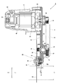
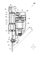
図2は図1のA-A部の断面図である。ここでは構造の理解の容易さから、モータ5の回転軸51と中間回転軸24とスピンドル33の中心軸を通過する断面の形状を示しているので注意されたい。揺動軸122(図1参照)を中心に揺動可能な切断部2は、アルミ合金製のフレーム10に、モータ5と鋸刃60を軸支するスピンドル33と、モータ5の回転軸51からスピンドル33への動力伝達機構(21~27、41、42等)を含んで構成される。モータ5はフレーム10の鋸刃60と同じ側に固定されるものであって、その回転軸51がフレーム10を貫通し、2つの軸受53、54によって軸支される。モータ5は、ユニバーサルモータであってブラシ52を備える。モータ5のステータとフレーム10との間には、冷却ファン56が設けられ、モータ5が回転するとモータカバー57の内部に冷却風を流すことによりモータ5を冷却する。モータ5の回転軸51の先端であって、フレーム10から反対側に突出した部分には第一プーリ21が設けられる。第一プーリ21の回転力はVベルト22を介して中間回転軸24の端部に固定された第二プーリ23に伝達される。第二プーリ23は第一プーリ21よりも大径に形成され、モータ5の回転軸51に対して減速された状態で中間回転軸24が回転する。第一プーリ21から第二プーリ23が配置される空間は、カバー9によって覆われる。
中間回転軸24はフレーム10の一面側から他面側に貫通するように配置され、並べて配置された2つの軸受26、27によって軸方向中央付近で軸支される。中間回転軸24に設けられた第二プーリが設けられる一端側と反対側の端部には第三プーリ25が設けられる。第三プーリ25はフレーム10と鋸刃60の間に配置され、第三プーリ25の回転面は、鋸刃60の回転面と平行になるように配置される。第三プーリ25の回転力はVベルト42を介してスピンドル33と同軸上に設けられた第四プーリ41に伝達される。Vベルト22及びVベルト42は、樹脂又はゴム等の弾性体によって生成される。第四プーリ41はスピンドル33に対して相対回転不能なように装着される動力伝達部材であって、第三プーリ25よりも大径に形成され、中間回転軸24に対してさらに減速された回転数で第四プーリ41が回転する。スピンドル33は鋸刃60を切断面と直交する方向に回転可能に保持する刃軸となるもので、鋸刃60の切断面と直交する方向に延びるように配置される。スピンドル33の左側端部には、鋸刃固定用の取付ボルト38によって円形の鋸刃60が固定される。鋸刃60は、例えば羽数が60個、直径が165mmのチップソーである。そして、鋸刃60をワークWに対して直角にあてて切断する、いわゆる直角切断時には、厚さTのワークを切断できる。
スピンドル33はフレーム10の厚さ方向の中心位置から鋸刃側に配置され、いわゆる片持ち式に支持される。このためフレーム10の厚さ方向の中心線(矢印10a付近の板厚さ方向の中心を通る線)よりも片側(左側)にスピンドル33が位置することになる。切断部2を左右方向に傾斜させて切断可能な卓上切断機1においては、作業性(視認性や可搬性)の観点から、スピンドル33の全長が短く、鋸刃60からフレーム10の厚さ方向中心位置までの距離Sが短い方が良い。さらに、フレーム10の中心位置から鋸刃60とは反対側の外面位置までの距離Lができるだけ短い方が良い。本実施例では、より深い切断部2の傾斜を可能にするため、フレーム10のスピンドルの軸支部分の下側角部は斜めに切り落とされたような形状の斜面部15aが形成される。本実施例ではさらに、2段ベルト構成を採用することによって、スピンドル33周りの径方向の寸法を抑えることができるため、モータ5の配置と合わせて傾斜時の切込深さを大きく取れるようになった。
作業者がハンドル7に設けられたスイッチ8(図1参照)を押すと、モータ5が作動し、回転軸51が回転する。回転軸51が回転すると、回転軸51の先端に取り付けられた第一プーリ21と、架け渡されたVベルト22を介して、中間回転軸24へ回転動力が伝達される。ここで、第二プーリ23は第一プーリ21よりも大径に形成されているため、中間回転軸24は、モータ5(回転軸51)から伝達される回転速度を減速するとともに、回転トルクを増大させて回転する。次に、中間回転軸24が回転すると、中間回転軸24の他方(鋸刃60側)の端部に取り付けられた第三プーリ25と、架け渡されたVベルト42を介して、第四プーリ41とスピンドル33へ回転動力が伝達される。この時、第三プーリ25の径よりも第四プーリ41の径の方が大きいので、中間回転軸24の回転速度は減速されてスピンドル33へ伝達される。すなわち、モータ5の回転は動力伝達機構によって2回減速されてスピンドル33に伝達される。スピンドル33が回転することで、鋸刃60はスピンドル33と一体的に回転することとなる。
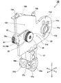
図3はフレーム10単体の斜め左側から見た斜視図である。フレーム10はアルミニウム合金の一体成型によって製造され、揺動軸から伸びるアーム部17と、アーム部17に連結されるモータ取付部11と鋸刃60の側面に延びる鋸刃取付部12によって主に構成される。アーム部17はアルミニウム合金の一体ブロックであり、その下側は、揺動軸122(図1参照)に軸支するための取付基台17a、17bが形成され、その中央には揺動軸122を貫通させる為の貫通穴18a、18bが形成される。アーム部17の上側の後方側のモータ取付部11は、鋸刃60を回転させる駆動源たるモータ5を保持する部分であって、モータ5の外径に対応した円筒部11bが形成され、円筒部11bの外側にはモータ5を収容するモータカバー57を固定するためのフランジ部分となっている。フランジ部分には3つのネジ孔11d(図3では2つしか見えない)が形成される。円筒部11bの内側には、モータ5の回転軸51を貫通させる為に貫通穴を形成すると共に軸受54を保持するための円筒部11aが形成され、円筒部11aの外周側には空気を通すための複数の風窓11cが形成される。風窓11cは、フレーム10を減肉して切断部2の重量を減らす働きもする。
アーム部17の上側の前方側には、鋸刃取付部12が形成される。鋸刃取付部12はアルミニウム合金等の金属の一体物で形成され、主要部分は削りだし加工によって成形される。鋸刃取付部12には鋸刃60の後方側半分の右側側面を覆う平面部12aと、平面部12aの外縁を鋸刃側に突出する外周面12bが形成される。外周面12bの外側にはカバー9(図1参照)を固定するためのネジ穴が形成された取付けリブ13a、13bが形成される。平面部12aの左側面のほぼ中央付近には、平面部12aから左側に突出する第三プーリ25と第四プーリ41の外周部を覆う左側面視で略長円状の壁部14が形成される。この壁部14の内側部分にて図示しないVベルト42が走行するが、壁部14は第三プーリ25と第四プーリ41の周囲に切粉等の粉塵が侵入することを抑制する働きを有する。ここで、鋸刃60を固定するためのスピンドル33には、円柱の外周のうち対向する2カ所が平面状に切り落とされたような平面部33aが形成される。一方、スピンドル33と同軸上にはめ込まれる第四プーリ41の内周側にも平面部33aに対応する平面部が形成され、これら平面部によってスピンドル33と第四プーリ41の周方向への相対回転を阻止する回り止めとして作用する。
図4は図2のフレーム10単体の斜め右側から見た斜視図である。フレーム10の平面部12aの右側側面の中央付近には中間回転軸24に軸支された第二プーリ23が保持される。中間回転軸24を軸支する部分は、軸受26、27を支持するために中央が凹状に窪んだ円筒状のサポート円筒部19が形成され、その後方側には肉厚が厚く形成された肉厚部15が形成される。肉厚部15は中間回転軸24とスピンドル33の回転精度を保つために、フレーム10の部分的な剛性を上げるために形成するものである。肉厚部15の後端部分は、後方の壁と右側壁の角部を斜めに切り落としたような斜面部15aが形成される。斜面部15aは、切断部2をスピンドル33が位置する側(右側)に最大傾斜させた際に鋸刃60による右傾斜切断(図8で後述)の切断深さを確保するために形成するものである。肉厚部15の後端付近には、貫通穴15bが開けられ、そこにピン31が圧入される。取付基台17a、17bの間の部分には揺動軸122の周囲を覆う軸カバー17cが設けられる。
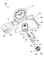
図5はフレーム10を左側から見た斜視図であり、スピンドル33の取付構造を説明するための展開図である。ここでは揺動軸を中心にフレーム10を切断方向に最大に移動させた時の状態であって図2の位置とは向きが異なるので注意されたい。フレーム10のスピンドル33の保持部分は、軸受34の外周リングを内面で支持する円筒状の壁部たるサポート円筒部16が形成され、その内部にスピンドル33が軸支される。ここではスピンドル33は円筒状であって、その外周側が軸受34で保持され、内周側が軸受32とピン31によってフレーム10に軸支される。軸受32と軸受34はニードルベアリング(針状ころ軸受)であり、シェル(円筒リング)の内側に金属製のニードル(針状ころ)が周方向に並んで複数保持されている。軸受32の内周に配置された複数のニードルは、フレーム10を貫通して保持される円柱状の金属製のピン31の外周面と接触し、軸受32がフレーム10に保持される。ピン31はフレーム10に形成された貫通穴15bに圧入により固定されるもので、軸受32の固定部材として作用し、ピン31自体は回転しない。スピンドル33の外周面側の軸受34は、内周に配置された複数のニードルがスピンドル33の外周面に接触する。スピンドル33の軸方向のフレーム10側(右側)約半分は、軸受32、34と共にサポート円筒部16内に収容され、円環状の押さえリング35によって軸受34が軸方向に抜け落ちないように保持される。押さえリング35は、周方向に等間隔でネジ穴を有し、3本のネジ36によってサポート円筒部16に形成されたネジ孔にネジ止めされる。
スピンドル33への動力伝達部材である第四プーリ41は、ネジ36を用いてスピンドル33の軸支が終わった後に装着され、Cリング44(図6参照)によってスピンドル33から抜け落ちないように保持される。スピンドル33には、外周面の対向する部分が平面状に形成された平面部33aが形成され、内周側には取付ボルト38(図2参照)を固定するための雌ねじ33bが形成される。スピンドル33の平面部33aは、第四プーリ41の内周面に形成された2つの平面部41aに当接するようにして取り付けられることにより、第四プーリ41とスピンドル33は相対回転ができないようにして連結される。第四プーリ41の外周側は、Vベルトの走行するプーリ部41cとなっており、軸方向端部には鋸刃60を保持する円環状の固定面41dが形成される。
図6は図2のスピンドル部30の拡大断面図である。尚、この図のうちスピンドル33の回転中心よりも上側はVベルト42の長手方向と平行な断面で有り、図中でスピンドル33の回転中心よりも下側は、回転中心とネジ36及び平面部33aを通る位置での断面図であるので注意されたい。ここで、スピンドル33は、フレーム10の肉厚部15のうち、左側(鋸刃60側)に開口するサポート円筒部16の中に、軸方向の約半分が収容されるようにして軸支される。本実施例では、スピンドル33は、軸方向に貫通する円筒形の軸受取付部が形成された部材であって、サポート円筒部16の底面16aに近い端部(右側端部)に径方向外側に大きく形成されたフランジ部33eが形成され、スピンドル33の外周側に配置された軸受34が軸方向にみてフレーム側(右側)にずれないように保持する。一方、スピンドル33の内周側には、段差部33dが形成され、軸方向にみてフレーム10側(右側)に近い側の内径が大きく、鋸刃60側(左側)の内径が小さく形成される。この段差部33dによりスピンドル33の内周側に配置された軸受34が鋸刃60側(左側)に移動することが阻止され、軸受構造を維持することができる。
軸受32、34は共にシェル形針状ころ軸受を用いる。シェル形針状ころ軸受は、薄い特殊鋼板を精密深絞り加工した外輪と、針状ころと、針状ころを案内する保持器により構成される軸受である。この形状は、外輪付き転がり軸受の中で最も断面高さが小さい形式であって,省スペース設計に適している。ここでは、研削されたスピンドル軸の外周面を直接軌道面として使用するため、内輪を省略できる。スピンドル33の外周側に軸受34を配置して、サポート円筒部16の内側に外輪を圧入するようにすれば軸受け34の軸方向の固定を必要としない。同様にしてスピンドル33の内周側に軸受32の外輪を圧入するようにすれば軸受32の軸方向の固定を必要としない。軸受32の内周側には、外周面が研削された金属製のピン31は配置され、ピン31の外周面を軸受32の軌道面として使用するため、軸受32の内輪を省略できる。ピン31はフレーム10の貫通穴15bに圧入により固定される。このようにしてスピンドル33がフレーム10のサポート円筒部16に取り付けられるが、そのあと、軸受34の軸方向に抜けることを防止するために押さえリング35が取り付けられ、3本のネジ36にて固定される。このような構造によりスピンドル33は軸方向にみて鋸刃60側への移動が阻止される。一方、軸方向に右側(鋸刃60とは反対側)には、スピンドル33のフランジ部33eがサポート円筒部16の底面16aに当接するのでそれ以上の移動は阻止される。その移動の際にスピンドル33と底面16aとの摩擦抵抗を減らすために、表面の摺動抵抗の低い金属リング45が底面16aに貼り付けられる。
本実施例では軸受32、34として軸端部をふさぐためのクローズエンド形式のシェル形針状ころ軸受を用いたが、これだけに限られずにその他の形式のシェル形針状ころ軸受、又は径方向の厚さが薄いその他の形式の軸受を用いても良い。さらに、シェル形針状ころ軸受であってもオープンエンド形式のものとしても良いし、潤滑オイルを保持するために針状ころの軸端の片側または両側にシールを内蔵した形式としたものであっても良い。
スピンドル33をフレーム10のサポート円筒部16の内側に軸支したら、次に第四プーリ41をスピンドル33に装着する。スピンドル33の外周側には平面部33aが形成され、第四プーリ41の内周側にも平面部41a(図5参照)が形成されるので、これらを対面させることによりスピンドル33と第四プーリ41が相対回転しない。また、第四プーリ41の平面部の端部が、スピンドル33の平面部33aの端部たる段差面33cに当接するので、第四プーリ41のフレーム10側(右側)への移動が制限される。また、スピンドル33の外周面に形成された円環溝33fにCリング44が装着されることにより第四プーリ41の鋸刃60側への軸方向の移動が制限される。
第四プーリ41は鋸刃60の片面を保持する円環状の固定面41dを有し、鋸刃60が固定用ワッシャ37と共に取付ボルト38にて締め付けられる。スピンドル33の鋸刃60側の内側には、取付ボルト38のネジ山と螺合する雌ねじ33bが形成されている。取付ボルト38は皿付きの六角ボルトであり、取り付けられた時にはその先端には隙間39を有する程度の長さとし、ピン31とは接触しないことが重要である。このようにしてスピンドル33がフレーム10に対していわゆる片持ち支持されることになるが、この際の軸受32、34、Vベルト42の軸方向に占める部分(プーリ部41cの軸方向長さ)が互いに部分的にオーバーラップするような位置関係となる。このため、スピンドル33の軸線上で見た鋸刃60からフレーム10の右側端面までの距離(図2の距離S+L)を短く形成することができた。また、2つの軸受のうち、スピンドル33の内側から軸支する軸受32よりも、軸受34を鋸刃60側(左側)に配置した。これによって、片持ち支持構造をとりつつも、軸支する範囲を広げてスピンドル33の回転精度を向上させることができると共に、右側へ切断部2を傾斜させたときに軸受34の後方部分(図6中のスピンドル33よりも下側に位置する部分)が軸受32の右端部よりも左側に位置するので、傾斜切断への影響を少なくすることができる。また、第四プーリ41に、軸受32と軸受27を外側から覆うように円筒窪み41bを形成し、スピンドル33の軸方向に見てVベルト42の走行面と軸受32と軸受27が部分的にオーバーラップするような位置関係とされるので、スピンドル33に対する曲げの力の作用を軽減できスピンドル33の回転精度が良くなる。
中間回転軸24はスピンドル33と平行に配設され、鋸刃60から離間する側を支持する軸受26とフレーム10の肉厚部15の厚さ方向のほぼ中間に位置する軸受27によって回転可能に支持される。中間回転軸24に固定される第二プーリ23と第三プーリ25はフレーム10の反対側に保持されるので、中間回転軸24の剛性が強く安定して保持される。一方、片持ち支持に近い形のスピンドル33は、軸支される部分、即ち軸受32、34の軸方向に占める位置が、軸受27の軸方向に占める位置と部分的にオーバーラップするように配置される。よって、フレーム10の肉厚部15にかかる曲げモーメントが軽減されるので、スピンドル33の回転精度が良くなる。尚、ここでは図示していないが、鋸刃60の卓上切断機1への取付け、取り外し時には、スピンドル33の回転をロックする図示しないロック機構を設けると良い。
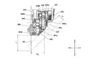
次に図7を用いて本実施例のスピンドル33の保持構造に至る改良過程を説明する。その前に、比較のため図12を用いて現行製品の卓上切断機におけるスピンドルの保持構造を説明する。図12において、鋸刃60を保持するスピンドル350は2つの軸受351aと351bによって軸支される。スピンドル350を回転させ得るための第四ギヤ352は、第二中間回転軸345の左端に設けられた第三ギヤ348と噛合する。第二中間回転軸345は2つの軸受346a、346bにより軸支され、軸受346a、346bの間に第二ギヤ347が配置される。第一中間回転軸333は軸受334aと334bによって軸支され、軸受334aと334bの間には第二ギヤ347と噛合する第一ギヤ335が設けられる。ここで用いられる軸受はすべてボールベアリングである。第一中間回転軸333の右側の端部には第二プーリ332が設けられ、図示しないモータの回転力によって駆動されるVベルト331によって駆動される。このように、従来のスピンドル保持構造では、動力を受ける第四ギヤ352の両側に配置された2つの軸受け351a、351bによってスピンドル350が保持される(両持ちされる)こと、鋸刃60と第四ギヤ352の間に軸受け351bが配置されることから、スピンドル350の軸方向の長さが長くなってしまう。そのため、鋸刃60とスピンドル350の軸線とケースの交差点までの距離WPが長くなってしまう。この結果、直角切断時の切断深さがTpに対して、傾斜切断時の切断深さがBpとなり、BpがTpに比べて小さくなってしまうという問題があった。
このような図12のスピンドル保持構造を改良した過程を説明するのが図7である。図7において(3)が本実施例のスピンドル保持構造であり、(1)及び(2)は(3)の構造に至るまでに考えた構造である。図7(1)はフレーム160に対して、スピンドル165を2つの軸受166、167にて片持ち支持するように構成したものである。ここで「片持ち支持」とは、スピンドル165に動力を伝える第四プーリ169から見て一方側にのみ設けられた軸受にて、フレーム160(170、10)に軸支されることを意図している。軸受167はスピンドル165の外周側に配置するが、同一外径のスピンドルの外側に2つの軸受を並べるように設けると、フレーム160に近い側の部分の形状が大きくなり、右側に傾斜させた傾斜切断時に不利になる。そのため、軸受166として小径のものを用いるようにした。その軸受166に合わせてスピンドル165の軸径が細く形成される。このように形成すれば、フレーム160の下側に斜面160aを形成することができる。この構成では、軸受167の占める軸方向長さB4と軸受166の占める軸方向長さB3が軸方向にオーバーラップしない。また、第四プーリ169が軸受167よりもさらに左側に突出しているので、ベルトV2の部分と軸受167の占める軸方向長さB4がオーバーラップしないので、全体の厚さEが厚くなってしまう。
図7(2)は、2つの軸受を軸方向にオーバーラップさせるように配置することにより厚さFを薄くしたものである。ここでは、スピンドル175を円筒状に形成し、円筒状の外側に軸受177を配置することは(1)と同じであるが、小径の軸受176を軸受177の右側に突出させるのでは無くてスピンドル175の内側に入れ込むようにした。しかしながらこのように内側に入れ込む構成にすると、軸受176の外周側が回転側となるので、内周側を固定端としなければならない。そこでフレーム170にから延びるピン171を用いて軸受176を軸支するようにした。このように構成することにより、矢印188の分だけスピンドル175の軸方向長さを短くすることができた。特に、軸受177の占める軸方向長さと軸受176の占める軸方向長さB43を短くすることができたので、コンパクトなスピンドルの保持構造を実現できた。
図7(3)は本実施例の形状である。本実施例では2つの軸受32、34の改良に加えて、Vベルト42の走行位置をさらに改良したものである。軸受32と軸受34の占める軸方向長さB43を、Vベルト42の占める軸方向長さV2をオーバーラップさせるようにしたので、矢印189の部分を更に詰めることができた。また、長さB43を軸受27の占める軸方向長さB2とも僅かにオーバーラップするようにした。このように小径の軸受32(ニードルベアリング)を大径の軸受(ニードルベアリング)34よりも鋸刃60から離れるようにオフセットさせ、かつ、小径と大径の軸受32、34が軸方向にオーバーラップさせるように配置したので、スピンドル33の長さも更に短くすることができ、片持ち支持式であっても剛性の高いスピンドル保持構造を実現できた。また、長さB43と長さB2を僅かにオーバーラップするように配置したので、中間回転軸24やスピンドル33の回転精度をさらに上げることが可能となった。
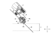
次に、切断部2を伝達機構部側に傾斜させた状態における切削作業について図8及び図9を参照して説明する。傾斜可能な切断部2を有する卓上切断機1の切削能力は、切断部2の傾斜状態におけるワークWへの切り込みの深さの程度に大きく関わる。切断部2を傾斜させない状態での切削作業において、ワークWに最も近接する鋸刃60を除く切断部2の部位はVベルト42であり、その際の切断深さは図2のTである。一方、切断部2を右側に傾斜した状態での切削作業において、ワークWに最も近接する鋸刃60を除く切断部2の部位は、カバー9の下面のうち 鋸刃60の垂直方向に最も離間する角部9aと、肉厚部15の斜面部15aと、第四プーリの角部41eである。これらの形状がワークWへの右斜めの切込深さに関わることとなる。
伝達機構部は、回転動力の伝達を2段ベルトによって行う構成のため、ギヤによって行うものと比べ、設計変更の自由度が高い。例えば、更に大きな減速比を要し、第二プーリ23をより大きな径にするような場合であっても、Vベルト42を長くする(中間回転軸24とスピンドル33との間隔を長くする)ことで、スピンドル33から下方へのカバー9の突出を抑制することができる。しかしながら中間回転軸24の位置がスピンドル33からみて鋸刃60の範囲内にあるように配置することは重要である。この配置の自由度により、切断部2を右側(伝達機構部側)に傾斜させた状態での切削加工において、第二プーリ23の径方向下端がワークWに干渉することがないように配置できた。
以上のように本実施例では、スピンドル33をいわゆる片持ち式に近いようにしてフレーム10の軸支することにより、フレーム10の中心線(図2参照)より第二プーリ23側の突出部分の大きさをきわめて小さくすることができた。具体的にはモータ5の軸方向において、回転軸51の一端から冷却ファン56が占める領域と同等の寸法範囲に伝達機構部を収容できた。これによって切断部2が小さくなり、小型化に伴う可搬性及び視認性の向上を実現できた。また、伝達機構部を小さくして鋸刃60の位置を右側へシフトさせることができ、さらに、突出部分の角部を斜めに切り落としたような形状としたので、切断部2を右側に傾斜して切削する場合において、比較的小径の鋸刃60であっても、切込深さBを十分確保することができる。更には従来よりも傾斜切断時の切込深さBを大きくするために鋸刃60を大径化しなくてすむので、フレーム10の切削方向への長さも大きくする必要が無いので、卓上切断機1についてもコンパクトなものとすることができる。
また、モータ5の回転を鋸刃60に伝達する伝達機構部をプーリとベルトによって構成してギヤを用いていないため、卓上切断機1の運転時に、ギヤの噛合による騒音が発生せず、静音性に優れたものとなる。更に、第二プーリ23を第三プーリ25及び第四プーリ41より鋸刃60から遠方に配置、すなわちVベルト42をVベルト22より鋸刃60側に配置している。このため、図8に示す傾斜状態において、Vベルト42(第四プーリ41)が傾斜の邪魔にならないため、傾斜時の切込深さBを大きくとることができる。
図9は、切断部2を伝達機構部側とは反対側、即ち左側に傾斜させた状態における切削状況を示すものである。鋸刃60の左側には固定用ワッシャ37と取付ボルト38しかないため、左側へは十分傾けることができる。この傾ける度合いは、傾動部116(図1参照)の傾斜範囲又は固定用ワッシャ37の斜面部37aによって制限される。ここで図8と図9を比較するとわかるように本実施例の卓上切断機1においては、右側への傾斜時の切込深さBが、左側への傾斜時の切込深さCの8割程度まで確保されていることが理解できよう。
図10は本発明の第二の実施例に係る卓上切断機のスピンドル保持部分の拡大断面図である。ここでは、中間回転軸24からスピンドル33への動力伝達をVベルトでなくて、2つの平ギヤ91、92としたものである。このようにVベルトを用いなくても同様の構成が実現できる。尚、平ギヤ92を用いる場合は、右傾斜切断時に平ギヤ92の角部分(矢印92a)付近においてワークWに干渉する恐れがある。従って、平ギヤ92の角部分を斜めに切り落とすようにするか、何らかのカバー等で覆うようにすることが好ましい。このように、動力伝達機構はVベルトだけで無くギヤを介するようにしても良い。また、モータ5に近い側のVベルト22も、ギヤやその他の伝達機構を用いるようにしても良い。
図11は、モータの回転力をスピンドル経由で鋸刃60に伝達するのでは無く、鋸刃60を挟むようにして両面側に配置された第一ローラ264と第二ローラ274を介して鋸刃60を回転させるようにしたものである。切断部202は、揺動軸部に軸支されるフレーム215とその外殻たるにハウジング257を含んで構成されている。フレーム215は鋸刃60の中心軸位置において鋸刃60を回転可能に保持するスピンドル233を片持ち式にて軸支する。モータ205は回転軸が鋸刃60の回転面と平行方向に延びるように配置され、回転軸先端のピニオン251によって回転力が第一ギヤ252と第二ギヤ261に伝達される。モータ205とピニオン251の間には、冷却ファン256が設けられ、モータ205と同期して回転する。第二ギヤ261は長く延びた回転軸260の上端に設けられ、回転軸260の下端であって鋸刃の側面に隣接する部分に第一ローラ264が設けられる。回転軸260は2つの軸受262と263によって回転可能なように軸支される。回転軸260と平行にさらなる回転軸270が設けられる。回転軸270は2つの軸受272と273によって可動カバー280によって軸支される。回転軸270は従動回転軸であって、下端に設けられた第二ローラ274が第一ローラ264と共に鋸刃60を挟むことにより、回転する第一ローラ264の摩擦力によって鋸刃60を回転させるようにした。そのため可動カバー280の上部には圧縮バネ282が設けられ、第二ローラ274を鋸刃60に対して所定の付勢力を付与するように構成した。回転軸270が軸支される可動カバー280は、回動軸281を中心に時計回りに90度程度回転させて、第二ローラ274を鋸刃60から離すことが可能となる。鋸刃60の装着又は取り外し時には可動カバー280を開いた状態で行われる。
フレーム215のスピンドル233が取り付けられる部分には、円筒部216が形成される。円筒部216、外側の軸受234、スピンドル233、内側の軸受232の形状や使用する部品は、図5で示したサポート円筒部16、軸受34、軸受32とほぼ同じにすれば良い。また図11ではよく見えないが、構造的には図6で示した第四プーリ41に相当する部材が、プーリ機構が無くて鋸刃60を固定するだけの保持部材241とした。従って、保持部材241の軸方向の長さやスピンドル233の軸方向の長さも図6に示した第四プーリ41やスピンドル33よりも短く構成できる。外側の軸受234の右側位置(反鋸刃位置)は、内側の軸受232の右側位置(反鋸刃位置)よりも左側(鋸刃60に近い側)に位置するようにされ、円筒部216の底面付近に隣接する外側部分の角部を斜めに切り落としたようにした斜面部215aが形成される。尚、図12の構造では外側の軸受234の軸方向への移動を押さえるために、円筒部216の内周側に形成した円筒溝内にはめ込まれるCリング235にて保持するようにした。しかしながら、外側の軸受234の抜け防止は、図6と同様に押さえリング35とネジ36を用いても良いし、その他の固定方法を採用しても良い。
第三の実施例においては、モータ205の配置方法が第一及び第二の実施例と異なる上に、モータ205から鋸刃60への動力伝達経路が全く異なるが、そのような卓上切断機であっても、スピンドル233を軸方向にオーバーラップさせるように配置された径が異なる2つの軸受(232、234)によって軸支するようにしたので、他の実施例と同様に大変コンパクトなスピンドル保持構造を実現できた。このようにスピンドル233には円筒部が形成され、円筒部の内側と外側にそれぞれ軸受(232、234)を配置し、外側の軸受234はフレーム215に形成された円筒部216の内壁部分との間に保持され、内側の軸受232はフレーム215からスピンドル233の軸方向に延びるように配置される金属製のピン231によって保持されるので、剛性が高くてスムーズに回転できるスピンドル保持構造を実現できた。第三の実施例においても、右側に傾斜させて切断するときの切断深さBを大きくとることが可能となり、左側に傾斜させるときの傾斜量とほぼ同じとすることができる。
このように本発明では、円筒形のスピンドルの外周側と内周側に針状ころ軸受を配置し、外周側の針状ころ軸受はフレーム部に固定された円筒部の内壁分で保持させて、内周側の針状ころ軸受はフレーム部に固定された金属ピンにて保持させるようにした。このため、スピンドルをフレームの一面側(鋸刃側)に軸支する片持ち支持式にもかかわらずに小型が可能となった。さらに、スピンドルへの動力を伝達する動力伝達部材が、スピンドルの鋸刃と2つの軸受との間に配置され、しかも動力伝達部材のベルト部又はギヤ部が軸受とオーバーラップするように配置されるので、剛性が高くスピンドルの振れを低減させたスピンドルの保持機構が実現できた。
以上、本発明を実施例に基づいて説明したが、本発明は上述の実施例に限定されるものではなく、その趣旨を逸脱しない範囲内で種々の変更が可能である。例えば、モータの回転力は、スピンドルに対して2つのVベルトを介して伝達されるように構成したが、一方を高トルク伝達に適したタイミングベルトにしてもよい。具体的には、Vベルト42をタイミングベルトに変更し、モータの回転力がVベルトに伝達され、Vベルトの回転力がタイミングベルトに伝達され、タイミングベルトの回転力がスピンドルに伝達されるよう伝な達経路とすることもできる。これによって、高トルクが発生する減速後のプーリ間の動力伝達をより確実に行うことができる。また、2つある動力伝達用のベルトのうち一方をVベルトにしたので、鋸刃が木材等に噛みこんでロック状態となったときにはVベルトがプーリ上で滑ることとなり、動力伝達部材の破損を抑制することができる。また例えば本発明の卓上切断機は、回転する切断刃を必要とする切断工具、研削工具等に広く用いることが可能で有り、例えば携帯用丸鋸等においても適用可能である。また、本発明の軸受構造は伝達機構部中の回転軸に対して適用することでフレームの小型を実現できるものであり、中間回転軸を軸支する2つの軸受を軸方向にオーバーラップさせることも可能である。
1…卓上切断機、2…切断部、5…モータ、7…ハンドル、8…スイッチ、9…カバー、10…フレーム、11…モータ取付部、11a…円筒部、11b…円筒部、11c…風窓、11d…ネジ孔、12…鋸刃取付部、12a…平面部、12b…外周面、13a…リブ、14…壁部、15…肉厚部、15a…斜面部、15b…貫通穴、16…サポート円筒部、16a…底面、17…アーム部、17a…取付基台、17c…軸カバー、18a…貫通穴、19…サポート円筒部、21…第一プーリ、22…Vベルト、23…第二プーリ、24…中間回転軸、25…第三プーリ、26,27…軸受、30…スピンドル部、31…ピン、32…軸受、33…スピンドル、33a…平面部、33b…雌ねじ、33c…段差面、33d…段差部、33e…フランジ部、33f…円環溝、34…軸受、35…リング、36…ネジ、37…固定用ワッシャ、37a…斜面部、38…取付ボルト、39…隙間、41…第四プーリ、41a…平面部、41b…円筒窪み、41c…プーリ部、41d…固定面、41e…角部、42…Vベルト、44…Cリング、45…金属リング、51…回転軸、52…ブラシ、53,54…軸受、56…冷却ファン、57…モータカバー、60…鋸刃、61…保護カバー、91,92…平ギヤ、111…LEDライト、112…ベース、113…回動操作部、114…ターンテーブル、115…フェンス、116…傾動部(傾斜部)、120…摺動部、121…当接面、122…揺動軸、124…揺動支持部、140…傾動軸、142…クランプ、143…傾斜支持部、145…ガイドバー、147…ストッパボルト、160…フレーム、165…スピンドル、166,167…軸受、169…第四プーリ、170…フレーム、171…ピン、175…スピンドル、176,177…軸受、202…切断部、205…モータ、215…フレーム、215a…斜面部、216…円筒部、231…ピン、232,234…軸受、233…スピンドル、235…Cリング、238…取付ボルト、241…保持部材、251…ピニオン、252…第一ギヤ、256…冷却ファン、257…ハウジング、260…回転軸、261…第二ギヤ、262,263…軸受、264…第一ローラ、270…回転軸、272,273…軸受、274…第二ローラ、280…可動カバー、281…回動軸、282…圧縮バネ、331…Vベルト、332…第二プーリ、333…第一中間回転軸、334a,334b…軸受、335…第一ギヤ、345…第二中間回転軸、346a,346b…軸受、347…第二ギヤ、348…第三ギヤ、350…スピンドル、351a,351b…軸受、352…第四ギヤ,W…ワーク(被切断材)
Claims (12)
- モータと、該モータによって回転されるスピンドルと、前記スピンドルに固定される丸鋸刃を有する切断部と、被切断材を載置可能なベース部と、前記切断部を前記ベース部に対して移動可能に保持する揺動支持部と、を有する卓上切断機であって、前記切断部は、前記丸鋸刃の切断面と直交する方向に前記丸鋸刃を回転可能に保持する前記スピンドルと、前記モータからの動力を前記スピンドルへ伝達する動力伝達機構と、前記スピンドルを軸支するフレームを有し、前記スピンドルは、軸方向にオーバーラップさせるように配置された径が異なる2つの軸受によって前記フレームに軸支されることを特徴とする卓上切断機。
- 前記スピンドルには前記軸受を保持する円筒部が形成され、該円筒部の内側と外側にそれぞれ前記軸受を配置し、外側の前記軸受は前記フレームに形成された円筒壁の内壁部分との間に保持され、内側の前記軸受は前記フレームから前記スピンドルの軸方向に延びるように配置される固定部材との間に保持されることを特徴とする請求項1に記載の卓上切断機。
- 前記固定部材は、前記フレームに取り付けられる金属製のピンであることを特徴とする請求項2に記載の卓上切断機。
- 前記スピンドルは、前記フレームの厚み方向に見て片側の面側に片持ち式に固定されることを特徴とする請求項3に記載の卓上切断機。
- 前記動力伝達機構は前記モータによって駆動されるものであって前記スピンドルと平行に配置される中間回転軸を有し、前記中間回転軸は2つの軸受により前記フレームに軸支され、前記スピンドルを保持する2つの軸受の占める全体の軸方向の長さ部分と、前記中間回転軸を保持する2つの軸受のうち一つの軸受の占める軸方向の長さ部分がオーバーラップするように配置されることを特徴とする請求項2又は3に記載の卓上切断機。
- 前記スピンドルに、ベルト又はギヤによって前記中間回転軸の回転を前記スピンドルに伝達するための動力伝達部材が装着され、前記動力伝達部材の前記ベルト又は前記ギヤの軸方向に占める長さ部分は、内側の前記軸受及び外側の前記軸受の占める軸方向の長さ部分とオーバーラップすることを特徴とする請求項5に記載の卓上切断機。
- 前記中間回転軸の前記丸鋸刃に近い端部にプーリが設けられ、前記動力伝達部材にプーリ部が形成され、前記プーリと前記プーリ部との間がベルトによって動力伝達されることを特徴とする請求項6に記載の卓上切断機。
- 前記中間回転軸の前記丸鋸刃に近い端部にギヤが設けられ、前記動力伝達部材の外周側にギヤ部が形成され、前記ギヤと前記ギヤ部が噛み合うことによって前記中間回転軸の回転力が前記スピンドルに伝達されることを特徴とする請求項6に記載の卓上切断機。
- 前記揺動支持部を前記ベース部に対して左右方向に傾斜可能なように支持する傾斜支持部を設け、前記スピンドルの内側の前記軸受の前記丸鋸刃から離れた端部の位置を、外側の前記軸受の前記丸鋸刃から離れた端部の位置よりも前記丸鋸刃に近づくように配置し、前記フレームに形成された前記円筒壁の取り付け部分の前記被切断材に近い部分に、前記揺動支持部を前記丸鋸刃に対して前記スピンドルが位置する側に最大傾斜させた際に前記被切断材との距離を確保するための斜面部を形成したことを特徴とする請求項7又は8に記載の卓上切断機。
- 前記軸受はシェル形針状ころ軸受であって、薄い鋼板を絞り加工した外輪と、その内側に配置された複数の針状ころと、該針状ころを案内する保持器により構成されることを特徴とする請求項1から9のいずれか一項に記載の卓上切断機。
- 被切断材に対して上下方向に移動可能なベース部と、モータにより回転駆動される丸鋸刃を有し、該丸鋸刃の切断面と直交する方向に前記丸鋸刃を回転可能に保持するスピンドルと、前記モータにより前記スピンドルを駆動する動力伝達機構を有し、前記スピンドルは軸受によってフレームに軸支される卓上切断機であって、前記フレームに前記スピンドルを軸支するための円筒部を設け、前記スピンドルは円筒形の軸受取付部を有し、前記軸受取付部の内側に小径のニードルベアリングを配置し、前記軸受取付部の外側と前記円筒部の間に大径のニードルベアリングを配置し、前記軸受取付部の内側に小径のニードルベアリングを配置し、前記小径のニードルベアリングの内側を前記フレームに固定されるピンにより保持し、前記小径のニードルベアリングを前記大径のニードルベアリングよりも丸鋸刃から離れるようにオフセットさせ、かつ、前記小径と大径のニードルベアリングが軸方向にオーバーラップさせるように配置したことを特徴とする卓上切断機。
- 前記ニードルベアリングは、外周側にシェルが設けられ、該シェルの内周側において複数のニードルが配置されるシェル形針状ころ軸であって、前記フレームの円筒部が形成された面と反対側の面であって、前記被切断材に近い部分に斜面部が形成されることを特徴とする請求項11に記載の卓上切断機。
Applications Claiming Priority (2)
| Application Number | Priority Date | Filing Date | Title |
|---|---|---|---|
| JP2016-042911 | 2016-03-05 | ||
| JP2016042911 | 2016-03-05 |
Publications (1)
| Publication Number | Publication Date |
|---|---|
| WO2017154522A1 true WO2017154522A1 (ja) | 2017-09-14 |
Family
ID=59790314
Family Applications (1)
| Application Number | Title | Priority Date | Filing Date |
|---|---|---|---|
| PCT/JP2017/005913 Ceased WO2017154522A1 (ja) | 2016-03-05 | 2017-02-17 | 卓上切断機 |
Country Status (1)
| Country | Link |
|---|---|
| WO (1) | WO2017154522A1 (ja) |
Cited By (6)
| Publication number | Priority date | Publication date | Assignee | Title |
|---|---|---|---|---|
| WO2019130980A1 (ja) * | 2017-12-28 | 2019-07-04 | 工機ホールディングス株式会社 | 切断機 |
| WO2020059667A1 (ja) * | 2018-09-21 | 2020-03-26 | 工機ホールディングス株式会社 | 切断機 |
| CN111295271A (zh) * | 2017-10-31 | 2020-06-16 | 工机控股株式会社 | 动力工具 |
| CN112518022A (zh) * | 2020-12-12 | 2021-03-19 | 湖南金立星机械科技有限公司 | 具有改进刚性架结构的切割单元及切割机 |
| CN115070966A (zh) * | 2022-08-10 | 2022-09-20 | 泉州达锋机械有限公司 | 一种切石装置 |
| US12569960B2 (en) | 2023-04-26 | 2026-03-10 | Black & Decker Inc. | Impact tool |
Citations (3)
| Publication number | Priority date | Publication date | Assignee | Title |
|---|---|---|---|---|
| JPS4885034U (ja) * | 1972-01-19 | 1973-10-16 | ||
| JP2006327090A (ja) * | 2005-05-27 | 2006-12-07 | Hitachi Koki Co Ltd | 卓上切断機 |
| JP2010274391A (ja) * | 2009-05-29 | 2010-12-09 | Hitachi Koki Co Ltd | 卓上切断機 |
-
2017
- 2017-02-17 WO PCT/JP2017/005913 patent/WO2017154522A1/ja not_active Ceased
Patent Citations (3)
| Publication number | Priority date | Publication date | Assignee | Title |
|---|---|---|---|---|
| JPS4885034U (ja) * | 1972-01-19 | 1973-10-16 | ||
| JP2006327090A (ja) * | 2005-05-27 | 2006-12-07 | Hitachi Koki Co Ltd | 卓上切断機 |
| JP2010274391A (ja) * | 2009-05-29 | 2010-12-09 | Hitachi Koki Co Ltd | 卓上切断機 |
Cited By (8)
| Publication number | Priority date | Publication date | Assignee | Title |
|---|---|---|---|---|
| CN111295271A (zh) * | 2017-10-31 | 2020-06-16 | 工机控股株式会社 | 动力工具 |
| EP3705248A4 (en) * | 2017-10-31 | 2021-08-18 | Koki Holdings Co., Ltd. | POWER TOOL |
| US11565333B2 (en) | 2017-10-31 | 2023-01-31 | Koki Holdings Co., Ltd. | Power tool |
| WO2019130980A1 (ja) * | 2017-12-28 | 2019-07-04 | 工機ホールディングス株式会社 | 切断機 |
| WO2020059667A1 (ja) * | 2018-09-21 | 2020-03-26 | 工機ホールディングス株式会社 | 切断機 |
| CN112518022A (zh) * | 2020-12-12 | 2021-03-19 | 湖南金立星机械科技有限公司 | 具有改进刚性架结构的切割单元及切割机 |
| CN115070966A (zh) * | 2022-08-10 | 2022-09-20 | 泉州达锋机械有限公司 | 一种切石装置 |
| US12569960B2 (en) | 2023-04-26 | 2026-03-10 | Black & Decker Inc. | Impact tool |
Similar Documents
| Publication | Publication Date | Title |
|---|---|---|
| WO2017154522A1 (ja) | 卓上切断機 | |
| CN101456089B (zh) | 台式切割机 | |
| JP5476798B2 (ja) | 卓上切断機 | |
| JP5429524B2 (ja) | 卓上切断機 | |
| US10850338B2 (en) | Electric power tool | |
| US20180021867A1 (en) | Reciprocating tool | |
| JP5862950B2 (ja) | セーバソー | |
| US11969810B2 (en) | Work machine | |
| EP1807235B1 (en) | Driver for a twin cutting device with counter rotating blades | |
| EP2508285B1 (en) | Dustproof structure for movable support section in cutting machine | |
| JP2018122396A (ja) | 切断機 | |
| JPWO2018100940A1 (ja) | 動力工具 | |
| JP6274522B2 (ja) | 切断機 | |
| JP2016016469A (ja) | 回転工具 | |
| JP5311284B2 (ja) | セーバソー | |
| US11565333B2 (en) | Power tool | |
| JP5305229B2 (ja) | 切断工具 | |
| JP4678165B2 (ja) | 直動テーブル装置 | |
| JP7286444B2 (ja) | 携帯用切断機 | |
| CN222133485U (zh) | 一种内置动力单元的刀塔 | |
| JP2008110410A (ja) | 電動工具 | |
| JP2012011652A (ja) | 切断機 | |
| JP2020172024A (ja) | 切断機 | |
| JP2018140598A (ja) | 切断機 | |
| WO2019187949A1 (ja) | 切断機 |
Legal Events
| Date | Code | Title | Description |
|---|---|---|---|
| NENP | Non-entry into the national phase |
Ref country code: DE |
|
| 121 | Ep: the epo has been informed by wipo that ep was designated in this application |
Ref document number: 17762865 Country of ref document: EP Kind code of ref document: A1 |
|
| 122 | Ep: pct application non-entry in european phase |
Ref document number: 17762865 Country of ref document: EP Kind code of ref document: A1 |
|
| NENP | Non-entry into the national phase |
Ref country code: JP |