WO2017154363A1 - スタータモータ - Google Patents
スタータモータ Download PDFInfo
- Publication number
- WO2017154363A1 WO2017154363A1 PCT/JP2017/001630 JP2017001630W WO2017154363A1 WO 2017154363 A1 WO2017154363 A1 WO 2017154363A1 JP 2017001630 W JP2017001630 W JP 2017001630W WO 2017154363 A1 WO2017154363 A1 WO 2017154363A1
- Authority
- WO
- WIPO (PCT)
- Prior art keywords
- armature
- magnet
- starter motor
- bearing
- magnetic center
- Prior art date
- Legal status (The legal status is an assumption and is not a legal conclusion. Google has not performed a legal analysis and makes no representation as to the accuracy of the status listed.)
- Ceased
Links
Images
Classifications
-
- F—MECHANICAL ENGINEERING; LIGHTING; HEATING; WEAPONS; BLASTING
- F02—COMBUSTION ENGINES; HOT-GAS OR COMBUSTION-PRODUCT ENGINE PLANTS
- F02N—STARTING OF COMBUSTION ENGINES; STARTING AIDS FOR SUCH ENGINES, NOT OTHERWISE PROVIDED FOR
- F02N11/00—Starting of engines by means of electric motors
Definitions
- the present invention relates to a starter motor used for starting an internal combustion engine.
- the starter motor is provided with an armature having a magnet and a core and a receiving member that rotatably supports the armature.
- the starter motor energizes the armature to generate rotational force, and starts the internal combustion engine by transferring the pinion to the ring gear and meshing with it.
- the idle stop starter motor employs a structure in which the ball bearing is attached to one end of the armature and supports the rotation while the internal clearance of the ball bearing regulates the distance that can be moved in the thrust direction. It was.
- an object of the present invention is to provide a starter motor capable of maintaining a stable thrust holding state even when the start frequency is high while using an inexpensive sliding bearing as a rotation support member of an armature.
- one of the desirable aspects of the present invention is as follows.
- the magnetic center of the magnet arranged on the outer periphery of the armature is offset from the magnetic center of the armature core in the axial direction of the shaft, and the bearing on the side where the magnet is offset is a cylindrical slide bearing.
- the shaft was inserted, and the end surface of the bearing was in contact with the side surface of the shaft so that it could rotate and slide.
- a magnetic attraction force is generated in the armature by offsetting the magnet, and the thrust load is applied in one direction as the thrust load, and the thrust position of the armature is held and defined in one direction.
- the thrust load can be rotationally supported, and an inexpensive rotational support structure can be configured.
- the starter motor 1 of the present embodiment is for starting an automobile engine, for example.
- the starter motor 1 has a mug switch 2, a pinion 3, and a motor body 4.
- the motor body 4 is rotatably supported by the bracket 21 via the plain bearings 12 and 13 in the armature 11.
- the armature 11 includes a shaft 10 serving as a rotating shaft, a core 7 fixed to the shaft 10, a coil 8 formed by winding a lead wire around the core 7, and a commutator 9 that receives a current supplied from the brush 17 to the coil 8. have.
- the shaft 10 has one end in the axial direction supported by a slide bearing (receiving member) 12 and the other end in the axial direction supported by a slide bearing 13. An end portion on one axial side of the shaft 10 is reduced in diameter via a step surface (side surface) 10a, and the reduced diameter end portion is inserted into the slide bearing 13 and is rotatably supported.
- the shaft 10 is supported so as to be able to rotate and slide in a state where the stepped surface 10a formed on one side in the axial direction of the shaft 10 is in contact with the end surface 12a of the slide bearing 12 and the movement to one side in the axial direction is restricted. ing.
- a plurality of magnets 14 are arranged on the outer periphery of the armature 11 so as to face each other.
- the plurality of magnets 14 are attached to the inner peripheral surface of the case 18 that covers the outside of the armature 11.
- the magnet 14 is mounted so that the magnetic center 15 of the magnet 14 is offset toward the commutator 9 with respect to the magnetic center 16 of the core 7.
- the slide bearing 12 disposed on the commutator 9 side is configured by a cylindrical slide bearing.
- the shaft 10 of the armature 11 is inserted into the bearing 12 and the step surface (side surface) of the shaft 10 is inserted into the end surface 12a of the bearing 12. 10a contacts.
- the magnet 14 is arranged so that the magnetic center 15 of the magnet 14 is closer to the bearing 12 than the magnetic center 16 of the core 7.
- the magnet 14 is magnetized with the magnetic flux density changed so that the magnetic center 15 of the magnet 14 is closer to the bearing 12 than the magnetic center 16 of the core 7.
- the magnet 14 is arranged with the magnetic center 15 of the magnet 14 offset to one side in the axial direction with respect to the magnetic center 16 of the core 7, so that the magnetic attraction force F is thrust on the armature 11.
- the thrust position of the armature 11 is held and defined in one direction.
- the sliding bearing 12 at one end can rotate and support a radial load and a thrust load, and the thrust bearing is supported by the end surface 12 a of the sliding bearing 12.
- the armature 11 is supported so as to be able to rotate and slide while being in contact with the bearing 12 on one axial side of the shaft (rotating shaft) 10. Therefore, the progress of wear and the increase in noise are suppressed, and it becomes possible to form a contact surface (end surface 12a) having a predetermined surface accuracy for supporting the thrust load only on the sliding bearing 12 at one end.
- the structure can be configured.
- the magnet 14 is offset so that the magnetic center 15 is positioned on the other side in the axial direction on the side opposite to the commutator 9 than the core center 16 of the core 7, and the armature 11 is axially moved by its magnetic attraction force.
- the same effect can be obtained by urging to the other side and applying the thrust load to the slide bearing 13 as a thrust load and supporting the thrust by the slide bearing 13.
- the magnet 14 may be made of materials having different magnetization characteristics so that the magnetic center 15 of the magnet 14 is closer to the bearing 12 than the magnetic center 16 of the core 7.
Landscapes
- Engineering & Computer Science (AREA)
- Chemical & Material Sciences (AREA)
- Combustion & Propulsion (AREA)
- Mechanical Engineering (AREA)
- General Engineering & Computer Science (AREA)
- Connection Of Motors, Electrical Generators, Mechanical Devices, And The Like (AREA)
Abstract
安価なすべり軸受をアーマチャーの回転支持部材に用いながら始動頻度が高い中でも安定したスラスト保持状態を維持することが可能なスタータモータを提供する。 アーマチャー11の外周に配置する磁石14の磁気中心15をアーマチャー11のコア7の磁気中心16からオフセットさせ、磁石14をオフセットさせた側の軸受を円筒のすべり軸受12とし、同軸受12にアーマチャー11のシャフト10が挿入されるとともに、同軸受12の端面12aにシャフト10の側面10aが接触して回転摺動可能な形状とした。
Description
本発明は、内燃機関始動用として用いられるスタータモータに関するものである。
スタータモータは、磁石とコアを有するアーマチャーと前記アーマチャーを回転支持する受け部材とを備え、アーマチャーに通電し回転力を発生すると共に、ピニオンをリングギヤに移送し噛合わせることで内燃機関を始動させる。
ここで、スタータモータの始動動作時の騒音を低減する方法として、アーマチャーのスラスト方向の移動可能距離を規制する構造が公知であり、アーマチャーのシャフトの一端寄りに円周方向の溝を形成しシャフトの溝にワッシャを装着するとともに、ワッシャの外周を拘束する方法が開示されている(特許文献1参照)。
近年、自動車の燃料消費低減として信号待ち等にエンジンを停止するアイドルストップシステムが注目されているが、エンジンの始動頻度増加に伴いスタータモータの要求動作回数が増加する結果、前記従来技術のスラスト方向の移動可能距離を規制する構造では、ワッシャとシャフトの接触部の摩耗が進展し騒音の増加を招くことが課題であった。
このため、アイドルストップ用スタータモータではボールベアリングをアーマチャーの一端に装着して回転支持しつつボールベアリングの内部隙間でスラスト方向の移動可能距離を規制する構造を採用するものの、コストアップの課題があった。
そこで、本発明の目的は、安価なすべり軸受をアーマチャーの回転支持部材に用いながら始動頻度が高い中でも安定したスラスト保持状態を維持することが可能なスタータモータを提供することにある。
上記課題を解決するため、本発明の望ましい態様の一つは次の通りである。当該スタータモータは、アーマチャーの外周に配置する磁石の磁気中心をアーマチャーのコアの磁気中心からシャフトの軸方向にオフセットさせ、磁石をオフセットさせた側の軸受を円筒すべり軸受とし、同軸受にアーマチャーのシャフトが挿入されるとともに、同軸受の端面にシャフトの側面が接触し回転摺動可能な形状とした。
本発明によれば、磁石をオフセットすることによりアーマチャーに磁気吸引力が生じ、スラスト荷重として一方向に印加し、アーマチャーのスラスト位置が一方向に保持し規定され、片端のすべり軸受でラジアル荷重とスラスト荷重を回転支持することが可能となり、安価な回転支持構造を構成することが可能となる。
以下、図面を用いて本発明の実施例を説明する。
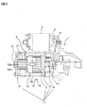
本実施例のスタータモータ1は、例えば自動車用エンジンを始動するためのものである。スタータモータ1は、マグスイッチ2、ピニオン3、モータ本体4を有している。モータ本体4は、アーマチャー11がすべり軸受12、13を介してブラケット21に回転可能に支承されている。アーマチャー11は、回転軸となるシャフト10と、シャフト10に固定されたコア7と、コア7に導線を捲回して構成されたコイル8と、ブラシ17からコイル8に電流の供給を受けるコンミテータ9を有している。
シャフト10は、軸方向一方側の端部がすべり軸受(受け部材)12に支持され、軸方向他方側の端部がすべり軸受13に支持されている。シャフト10の軸方向一方側の端部は、段差面(側面)10aを介して縮径されており、その縮径された端部がすべり軸受13に挿入されて回転可能に支持されている。シャフト10は、シャフト10の軸方向一方側に形成されている段差面10aがすべり軸受12の端面12aに接触して軸方向一方側への移動が規制された状態で回転摺動可能に支持されている。
アーマチャー11の外周には、複数の磁石14が対向して配置されている。複数の磁石14は、アーマチャー11の外側を覆うケース18の内周面に装着されている。磁石14は、コア7の磁気中心16に対して磁石14の磁気中心15がコンミテータ9側にオフセットして装着されている。そして、コンミテータ9側に配置されるすべり軸受12は円筒すべり軸受で構成され、同軸受12にアーマチャー11のシャフト10が挿入されるとともに、同軸受12の端面12aにシャフト10の段差面(側面)10aが接触する構造となっている。
磁石14は、磁石14の磁気中心15がコア7の磁気中心16よりも軸受12に近くなるように配置されている。例えば磁石14は、磁石14の磁気中心15がコア7の磁気中心16より軸受12に近くなるように磁束密度が変化した状態で着磁されている。
スタータモータ1は、不図示のバッテリーからマグスイッチ2の内部に収納された励磁コイルに電流が流れると、プランジャ5が吸引され、ピニオン3がシフトレバー6を介してエンジンに装着されたリングギヤに向かって移動し、ピニオン3がリングギヤに噛み合わされる。マグスイッチ2のプランジャ5が吸引すると同時に、モータ本体4に電流が流れ回転エネルギーを得るとともに、回転エネルギーがピニオン3に伝達し、リングギヤを回転させエンジンを始動させる。
本実施例の構成によれば、磁石14を磁石14の磁気中心15がコア7の磁気中心16に対して軸方向一方側にオフセットして配置することにより、アーマチャー11に磁気吸引力Fがスラスト荷重として一方向に印加し、アーマチャー11のスラスト位置が一方向に保持し規定される。そして、片端のすべり軸受12は、ラジアル荷重とスラスト荷重を回転支持することが可能となり、すべり軸受12の端面12aでスラスト支持する。
アーマチャー11は、シャフト(回転軸)10の軸方向一方側において軸受12と接触した状態で回転摺動可能に支持される。したがって、摩耗の進展と騒音増加が抑制され、片端のすべり軸受12のみにスラスト荷重を支持するための所定の面精度を有する接触面(端面12a)を形成することが可能となり、安価な回転支持構造を構成することが可能となる。
上記実施例のほか、磁石14をコア7のコア中心16よりも反コンミテータ9側である軸方向他方側に磁気中心15が位置するようにオフセットさせて、アーマチャー11をその磁気吸引力により軸方向他方側に付勢してすべり軸受13にスラスト荷重として印可し、すべり軸受13でスラスト支持することで同様の効果が得られる。
なお、上記実施例は自動車用のスタータモータにおいて説明したが、これに限られず、同様の構造の内燃機関用スタータにも適用が可能であり、この場合も同様の効果を得る。
また、磁石14は、磁石14の磁気中心15がコア7の磁気中心16より軸受12に近くなるように、磁化特性の異なる材料を用いてもよい。例えば磁化特性の異なる2種類の磁石を軸方向に装着する、もしくは磁束密度を軸方向に変化させながら着磁することでもアーマチャーにスラスト荷重を与えることが可能となり、スラスト位置が1方向に保持規制され、同様の効果が得られる。
1 スタータモータ
2 マグスイッチ
3 ピニオン
4 モータ本体
5 プランジャ
6 シフトレバー
7 コア
8 コイル
9 コンミテータ
10 シャフト
10a 段差面(側面)
11 アーマチャー
12 すべり軸受
12a 端面
13 すべり軸受
14 磁石
15 磁石の磁気中心
16 コアの磁気中心
F 磁気吸引力
2 マグスイッチ
3 ピニオン
4 モータ本体
5 プランジャ
6 シフトレバー
7 コア
8 コイル
9 コンミテータ
10 シャフト
10a 段差面(側面)
11 アーマチャー
12 すべり軸受
12a 端面
13 すべり軸受
14 磁石
15 磁石の磁気中心
16 コアの磁気中心
F 磁気吸引力
Claims (5)
- 磁石と、
コアを有するアーマチャーと、
前記アーマチャーと接触する受け部材と、を備え、
前記磁石の磁気中心が前記コアの磁気中心より前記受け部材に近くなるように形成され、
前記アーマチャーは、シャフトの軸方向において前記受け部材と接触状態となることを特徴とするスタータモータ。 - 前記磁石は、当該磁石の磁気中心が前記コアの磁気中心より前記受け部材に近くなるように配置されていることを特徴とする請求項1に記載のスタータモータ。
- 前記磁石は、当該磁石の磁気中心が前記コアの磁気中心より前記受け部材に近くなるように磁束密度が変化した状態で着磁されていることを特徴とする請求項1に記載のスタータモータ。
- 前記磁石は、当該磁石の磁気中心が前記コアの磁気中心より前記受け部材に近くなるように磁化特性の異なる材料が用いられていることを特徴とする請求項1に記載のスタータモータ。
- 前記シャフトは、段差面を介して縮径された端部を有しており、該端部が前記受け部材に挿入されて、前記段差面が前記受け部材の端面に接触した状態で回転摺動可能に支持されていることを特徴とする請求項1に記載のスタータモータ。
Priority Applications (2)
| Application Number | Priority Date | Filing Date | Title |
|---|---|---|---|
| JP2018504032A JP6533008B2 (ja) | 2016-03-07 | 2017-01-19 | スタータモータ |
| CN201780004835.6A CN108713095B (zh) | 2016-03-07 | 2017-01-19 | 起动电动机 |
Applications Claiming Priority (2)
| Application Number | Priority Date | Filing Date | Title |
|---|---|---|---|
| JP2016042952 | 2016-03-07 | ||
| JP2016-042952 | 2016-03-07 |
Publications (1)
| Publication Number | Publication Date |
|---|---|
| WO2017154363A1 true WO2017154363A1 (ja) | 2017-09-14 |
Family
ID=59789223
Family Applications (1)
| Application Number | Title | Priority Date | Filing Date |
|---|---|---|---|
| PCT/JP2017/001630 Ceased WO2017154363A1 (ja) | 2016-03-07 | 2017-01-19 | スタータモータ |
Country Status (3)
| Country | Link |
|---|---|
| JP (1) | JP6533008B2 (ja) |
| CN (1) | CN108713095B (ja) |
| WO (1) | WO2017154363A1 (ja) |
Cited By (2)
| Publication number | Priority date | Publication date | Assignee | Title |
|---|---|---|---|---|
| DE102019103421A1 (de) | 2018-02-13 | 2019-08-14 | Denso Corporation | Anlasser |
| JP2020186706A (ja) * | 2019-05-16 | 2020-11-19 | 株式会社デンソー | モータ |
Citations (5)
| Publication number | Priority date | Publication date | Assignee | Title |
|---|---|---|---|---|
| JPS63213441A (ja) * | 1987-03-02 | 1988-09-06 | Shinano Totsuki Kk | 直流モ−タのロ−タ用マグネツト材料の製造方法 |
| JPH0511763U (ja) * | 1991-07-24 | 1993-02-12 | 澤藤電機株式会社 | 低騒音モータ |
| JPH0652377U (ja) * | 1993-06-30 | 1994-07-15 | 長野日本電産株式会社 | マグネットロータ形直流モータの回転音低減構造 |
| JPH10271787A (ja) * | 1997-03-28 | 1998-10-09 | Asmo Co Ltd | 小型モータのスラスト方向ガタ異音防止構造 |
| JP2001065436A (ja) * | 1999-08-27 | 2001-03-16 | Hitachi Ltd | スタータ |
Family Cites Families (6)
| Publication number | Priority date | Publication date | Assignee | Title |
|---|---|---|---|---|
| JPS58198143A (ja) * | 1982-05-15 | 1983-11-18 | Matsushita Electric Works Ltd | モ−タ |
| JPH0668439A (ja) * | 1992-08-20 | 1994-03-11 | Ebara Corp | Vtr用ドラムモーター |
| CN1030127C (zh) * | 1992-10-29 | 1995-10-18 | 株式会社三协精机制作所 | 有刷小型直流电动机 |
| DE69407159T2 (de) * | 1994-04-14 | 1998-04-23 | Sankyo Seiki Seisakusho Kk | Kleiner Gleichstrommotor mit Bürsten und Musikgerät |
| JP2006304395A (ja) * | 2005-04-15 | 2006-11-02 | Denso Corp | 回転電機 |
| JP5217205B2 (ja) * | 2007-03-27 | 2013-06-19 | ソニー株式会社 | モータ |
-
2017
- 2017-01-19 JP JP2018504032A patent/JP6533008B2/ja not_active Expired - Fee Related
- 2017-01-19 CN CN201780004835.6A patent/CN108713095B/zh not_active Expired - Fee Related
- 2017-01-19 WO PCT/JP2017/001630 patent/WO2017154363A1/ja not_active Ceased
Patent Citations (5)
| Publication number | Priority date | Publication date | Assignee | Title |
|---|---|---|---|---|
| JPS63213441A (ja) * | 1987-03-02 | 1988-09-06 | Shinano Totsuki Kk | 直流モ−タのロ−タ用マグネツト材料の製造方法 |
| JPH0511763U (ja) * | 1991-07-24 | 1993-02-12 | 澤藤電機株式会社 | 低騒音モータ |
| JPH0652377U (ja) * | 1993-06-30 | 1994-07-15 | 長野日本電産株式会社 | マグネットロータ形直流モータの回転音低減構造 |
| JPH10271787A (ja) * | 1997-03-28 | 1998-10-09 | Asmo Co Ltd | 小型モータのスラスト方向ガタ異音防止構造 |
| JP2001065436A (ja) * | 1999-08-27 | 2001-03-16 | Hitachi Ltd | スタータ |
Cited By (3)
| Publication number | Priority date | Publication date | Assignee | Title |
|---|---|---|---|---|
| DE102019103421A1 (de) | 2018-02-13 | 2019-08-14 | Denso Corporation | Anlasser |
| DE102019103421B4 (de) * | 2018-02-13 | 2020-12-17 | Denso Corporation | Anlasser |
| JP2020186706A (ja) * | 2019-05-16 | 2020-11-19 | 株式会社デンソー | モータ |
Also Published As
| Publication number | Publication date |
|---|---|
| CN108713095A (zh) | 2018-10-26 |
| JP6533008B2 (ja) | 2019-06-19 |
| JPWO2017154363A1 (ja) | 2018-08-09 |
| CN108713095B (zh) | 2021-06-04 |
Similar Documents
| Publication | Publication Date | Title |
|---|---|---|
| US9722478B2 (en) | Stepping motor | |
| US20110193434A1 (en) | Starting device | |
| KR101667289B1 (ko) | Bldc 모터용 볼베어링의 전식 방지 샤프트 구조체 | |
| JP5145125B2 (ja) | 磁石式発電機 | |
| JP6533008B2 (ja) | スタータモータ | |
| US10309458B2 (en) | Brushless motor | |
| JP2003174761A5 (ja) | ||
| JP2009002464A (ja) | 磁気軸受装置およびこれを備えた工作機械 | |
| JP2007202324A (ja) | ブラシレスモータ | |
| US6930430B2 (en) | Armature support structure of starter for automotive engine | |
| JP5322033B2 (ja) | 計器用駆動装置 | |
| CN103795192A (zh) | 电机 | |
| CN103812246B (zh) | 马达以及马达的制造方法 | |
| KR20090085703A (ko) | 직류 모터 | |
| JPS63213453A (ja) | マグネツトロ−タ形直流モ−タの回転音低減構造 | |
| US3879624A (en) | Rotary solenoids in brush-application gear | |
| JP2010154704A (ja) | 電動モータ及びエンジン始動装置 | |
| WO2015182630A1 (ja) | スタータ | |
| JP2005308109A (ja) | 電磁ブレーキ内蔵モータ | |
| JP2017180129A (ja) | エンジン始動システム | |
| JPH0528381Y2 (ja) | ||
| JPH0754842A (ja) | ころがり軸受 | |
| JP2008267576A (ja) | 焼ばめ方法および焼ばめ装置 | |
| JPH06303757A (ja) | Pm型ステッピングモータ | |
| JP2014018041A (ja) | ステッピングモータ |
Legal Events
| Date | Code | Title | Description |
|---|---|---|---|
| ENP | Entry into the national phase |
Ref document number: 2018504032 Country of ref document: JP Kind code of ref document: A |
|
| NENP | Non-entry into the national phase |
Ref country code: DE |
|
| 121 | Ep: the epo has been informed by wipo that ep was designated in this application |
Ref document number: 17762709 Country of ref document: EP Kind code of ref document: A1 |
|
| 122 | Ep: pct application non-entry in european phase |
Ref document number: 17762709 Country of ref document: EP Kind code of ref document: A1 |