WO2017150347A1 - コヒーレント光受信器の同相除去比測定装置,及び測定方法 - Google Patents
コヒーレント光受信器の同相除去比測定装置,及び測定方法 Download PDFInfo
- Publication number
- WO2017150347A1 WO2017150347A1 PCT/JP2017/006926 JP2017006926W WO2017150347A1 WO 2017150347 A1 WO2017150347 A1 WO 2017150347A1 JP 2017006926 W JP2017006926 W JP 2017006926W WO 2017150347 A1 WO2017150347 A1 WO 2017150347A1
- Authority
- WO
- WIPO (PCT)
- Prior art keywords
- signal
- optical
- light
- frequency
- rejection ratio
- Prior art date
- Legal status (The legal status is an assumption and is not a legal conclusion. Google has not performed a legal analysis and makes no representation as to the accuracy of the status listed.)
- Ceased
Links
Images




Classifications
-
- H—ELECTRICITY
- H04—ELECTRIC COMMUNICATION TECHNIQUE
- H04B—TRANSMISSION
- H04B10/00—Transmission systems employing electromagnetic waves other than radio-waves, e.g. infrared, visible or ultraviolet light, or employing corpuscular radiation, e.g. quantum communication
- H04B10/07—Arrangements for monitoring or testing transmission systems; Arrangements for fault measurement of transmission systems
- H04B10/073—Arrangements for monitoring or testing transmission systems; Arrangements for fault measurement of transmission systems using an out-of-service signal
- H04B10/0731—Testing or characterisation of optical devices, e.g. amplifiers
-
- H—ELECTRICITY
- H04—ELECTRIC COMMUNICATION TECHNIQUE
- H04B—TRANSMISSION
- H04B10/00—Transmission systems employing electromagnetic waves other than radio-waves, e.g. infrared, visible or ultraviolet light, or employing corpuscular radiation, e.g. quantum communication
- H04B10/60—Receivers
- H04B10/61—Coherent receivers
- H04B10/615—Arrangements affecting the optical part of the receiver
- H04B10/6151—Arrangements affecting the optical part of the receiver comprising a polarization controller at the receiver's input stage
-
- G—PHYSICS
- G01—MEASURING; TESTING
- G01M—TESTING STATIC OR DYNAMIC BALANCE OF MACHINES OR STRUCTURES; TESTING OF STRUCTURES OR APPARATUS, NOT OTHERWISE PROVIDED FOR
- G01M11/00—Testing of optical apparatus; Testing structures by optical methods not otherwise provided for
- G01M11/02—Testing optical properties
-
- H—ELECTRICITY
- H04—ELECTRIC COMMUNICATION TECHNIQUE
- H04B—TRANSMISSION
- H04B10/00—Transmission systems employing electromagnetic waves other than radio-waves, e.g. infrared, visible or ultraviolet light, or employing corpuscular radiation, e.g. quantum communication
- H04B10/60—Receivers
- H04B10/61—Coherent receivers
- H04B10/614—Coherent receivers comprising one or more polarization beam splitters, e.g. polarization multiplexed [PolMux] X-PSK coherent receivers, polarization diversity heterodyne coherent receivers
-
- H—ELECTRICITY
- H04—ELECTRIC COMMUNICATION TECHNIQUE
- H04B—TRANSMISSION
- H04B10/00—Transmission systems employing electromagnetic waves other than radio-waves, e.g. infrared, visible or ultraviolet light, or employing corpuscular radiation, e.g. quantum communication
- H04B10/60—Receivers
- H04B10/61—Coherent receivers
- H04B10/615—Arrangements affecting the optical part of the receiver
-
- H—ELECTRICITY
- H04—ELECTRIC COMMUNICATION TECHNIQUE
- H04B—TRANSMISSION
- H04B10/00—Transmission systems employing electromagnetic waves other than radio-waves, e.g. infrared, visible or ultraviolet light, or employing corpuscular radiation, e.g. quantum communication
- H04B10/60—Receivers
- H04B10/61—Coherent receivers
- H04B10/616—Details of the electronic signal processing in coherent optical receivers
Definitions
- the present invention relates to an in-phase rejection ratio measuring apparatus and method for a coherent optical receiver using two-tone light.
- Non-Patent Document 1 measures and determines the output from each PD before connecting the balanced PD. It is to be calculated with the formula given.
- Non-Patent Document 2 Keysight (formerly Agilent) recognizes the necessity of measuring frequency characteristics of CMRR at the coherent measurement technology forum, but has not yet provided a specific measurement solution (Non-Patent Document 2 below).
- Patent Document 1 is not related to the measurement technique, but it automatically adjusts the gain of the differential transimpedance amplifier (TIA) in the latter stage of the balanced PD, and has excellent CMRR. It relates to the receiver.
- TIA differential transimpedance amplifier
- OIF's latest 100 Gbps polarization multiplexing integrated coherent receiver standard measures the output of each PD and then connects the balanced PD to a differential transimpedance amplifier (TIA) at the subsequent stage. For this reason, the CMRR of the signal output from the TIA is affected by the error of the connection portion and the characteristics of the differential TIA, and therefore has a problem that it is different from the measured value.
- TIA differential transimpedance amplifier
- the optical receiver described in the international publication WO2013-057967 pamphlet automatically adjusts the gain of the differential TIA and keeps the CMRR high, but only adjusts the amplitude of the differential TIA. There is a problem that the delay time difference cannot be adjusted.
- an object of the present invention is to provide a method and apparatus that can easily measure the CMRR frequency characteristics of an optical receiver.
- Another object of the present invention is to provide a method and apparatus for adjusting amplitude and delay time in a coherent optical receiver to be measured, thereby providing an optical receiver having good CMRR specification over a wide band. To do.
- a light having a measurement frequency ( ⁇ [hz]) is branched and has a first optical two-tone signal that is a signal light having a frequency difference ( ⁇ [hz]) and a frequency difference ( ⁇ + ⁇ [hz]). If a second optical two-tone signal that is local light is obtained, input to a coherent receiver to be measured, and an electrical signal output from the receiver is measured, the frequency ⁇ for the component of the frequency ⁇ [hz] is obtained.
- the signal intensity ratio of the component of ⁇ [hz] gives the signal light side CMRR. Further, the signal intensity ratio of the frequency ⁇ + ⁇ [hz] component to the frequency ⁇ [hz] component gives the local light side CMRR.
- the CMRR characteristics of the receiver can be understood by repeating the measurement of the signal light side CMRR or the local light side CMRR while changing the measurement frequency ( ⁇ [hz]).
- the present invention can provide a method and apparatus that can easily measure the CMRR frequency characteristics of an optical receiver.
- the present invention provides a method and apparatus for adjusting the amplitude and delay time in a coherent optical receiver that is a measurement target, thereby providing an optical receiver having good CMRR specification over a wide band.
- FIG. 1 is a block diagram showing an in-phase rejection ratio measuring apparatus for a coherent optical receiver according to the present invention.
- FIG. 2 is a diagram conceptually describing the first optical two-tone signal (Sig) and the second optical two-tone signal (LO).
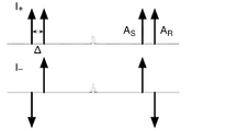
- FIG. 3 is a conceptual diagram showing two-tone light on the I channel side.
- FIG. 4 is a conceptual diagram showing a spectrum of an electric signal output from the balanced PD in the coherent optical receiver.
- FIG. 5 shows the output spectrum of the I channel based on the electrical signal output from the balanced PD.
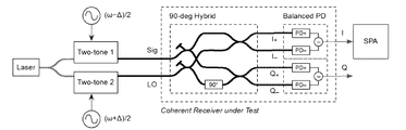
- FIG. 6 is a conceptual diagram showing the configuration of the experimental system in the example.
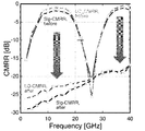
- FIG. 7 is a graph instead of a drawing showing the measurement results of the signal light side CMRR and the local light emission side CMRR before (before) and after (after) adjustment of the variable delay line.
- FIG. 1 is a block diagram showing an in-phase rejection ratio measuring apparatus for a coherent optical receiver according to the present invention.
- the 1st side surface of this invention is related with the common mode rejection ratio measuring apparatus of a coherent optical receiver.
- the common-mode rejection ratio (CMRR) is also called a common-mode rejection ratio and is a measure of a tendency to remove an input signal common to two inputs in a differential amplifier circuit or the like.
- a coherent optical receiver is an optical receiver that is also called a coherent receiver and a coherent optical receiver module (such as a research report on a coherent optical communication system published by the Association for Promotion of Mechanical Systems). It is a known optical receiver as described in International Publication WO 2012-086831 A1 pamphlet.
- the coherent optical receiver includes a signal light input unit 21 to which signal light is input, a local light input unit 23 to which local light is input, a 90 ° optical hybrid 25, and balanced PDs (photodetectors) 27 and 29. Then, the obtained signal light and local light are respectively branched by the branching unit. The branched signal light and the branched local light are combined by a multiplexing unit such as a coupler, and on the I channel side, the two-tone light is an optical signal synthesized in phase and in reverse phase.
- a multiplexing unit such as a coupler
- the remaining branched light of the branched local light is converted in phase by 90 ° and guided with the remaining branched light of the signal light to become two-tone light on the Q channel side.
- These two-tone lights are detected by a balanced PD (light detector).
- the in-phase rejection ratio measuring device 1 of the coherent optical receiver at the measurement frequency ( ⁇ [hz]) is a device that measures the in-phase rejection ratio of the optical receiver at an arbitrary wavelength ⁇ .
- ⁇ [hz] is usually 1 MHz or more and 500 GHz or less, and may be 10 MHz or more and 100 GHz or less.
- the light having the measurement frequency ( ⁇ [hz]) is preferably emitted from a laser light source, and is preferably continuous light (CW light).
- the laser light source is preferably one that can sweep or change the wavelength.
- This apparatus includes a branching unit 5 for branching light having a measurement frequency ( ⁇ [hz]) from a laser light source 3, a first optical two-tone generator 7, a second optical two-tone generator 9, And an electric signal measuring device 13 for measuring and analyzing the output electric signal output from the coherent optical receiver 11.
- a branching unit 5 for branching light having a measurement frequency ( ⁇ [hz]) from a laser light source 3, a first optical two-tone generator 7, a second optical two-tone generator 9, And an electric signal measuring device 13 for measuring and analyzing the output electric signal output from the coherent optical receiver 11.
- branching unit a known branching device can be used as long as it splits the input light.
- branching unit examples include a coupler that splits the intensity of input light, a beam splitter (BS), and a modified beam splitter (PBS).
- BS beam splitter
- PBS modified beam splitter
- the first optical two-tone generator 7 receives the first branched light branched by the branching unit 5 and generates a first optical two-tone signal that is signal light.
- the first optical two-tone signal has a frequency difference ( ⁇ [hz]) lower than the measurement frequency.
- the frequency difference is obtained by subtracting the frequency of the lower sideband (LSB) signal from the frequency of the upper sideband (USB) signal.
- ⁇ is, for example, from 1 / 1,000,000 to 1 / 1,000, and may be from 1 / 100,000 to 1 / 10,000.
- ⁇ is preferably 100 kHz or more and 1 MHz or less.
- a known optical two-tone generator can be used as long as it can generate two optical signals shifted from the reference frequency by a predetermined frequency.
- a DSB (both side band) modulator or a DSB-SC modulator may be used as the optical two-tone generator.
- the light two-tone light preferably has the same intensity of the two optical signals.
- the second optical two-tone generating device 9 is a device that receives the second branched light branched by the branching unit 5 and generates a second optical two-tone signal that is local light.
- the second optical two-tone signal has a frequency difference ( ⁇ + ⁇ [hz]) higher than the measurement frequency. It is preferable that the light intensity of the first optical two-tone signal and the second optical two-tone signal are approximately the same. In particular, it is preferable that the two optical signals constituting the first optical two-tone signal and the two optical signals constituting the second optical two-tone signal have the same intensity.
- the electrical signal measurement device 13 receives an output electrical signal output from the coherent optical receiver 11 that is a measurement target of the common-mode rejection ratio (CMRR), measures, for example, the light intensity, and uses this to analyze the CMRR.
- CMRR common-mode rejection ratio
- An example of the electric signal measuring device 13 is a known spectrum analyzer, but it is preferable to use an electric signal measuring device used in coherent optical communication.
- the electrical signal measuring device 13 compares the intensity of the electrical signal corresponding to the frequency ⁇ [hz] output as a differential component of the first optical 2-tone signal that is signal light and the second optical 2-tone signal that is local light. and I omega, the intensity ratio of the intensity I omega-[Delta] [omega electrical signal corresponding to the frequency ( ⁇ - ⁇ [hz]) only the first optical two-tone signal which is a signal light having common mode rejection of the signal light side It has a function of obtaining a ratio (CMRR).
- CMRR ratio
- the electrical signal measuring device 13 compares the intensity of the electrical signal corresponding to the frequency ⁇ [hz] output as a differential component of the first optical 2-tone signal that is signal light and the second optical 2-tone signal that is local light. and I omega, the frequency difference included in only the second optical two-tone signal is the local light ( ⁇ + ⁇ [hz]) from the intensity ratio of the intensity I omega + [Delta] [omega of electrical signals corresponding to, local light side common mode rejection ratio (CMRR It is preferable to further have a function for obtaining a).
- CMRR local light side common mode rejection ratio
- the above can be used, for example, as a device for measuring an in-phase signal rejection ratio for a single polarization (for example, X polarization) I signal component.
- the branching unit 5 branches the laser light having the measurement frequency ( ⁇ [hz]) emitted from the laser light source 3 to obtain the first branched light and the second branched light. At this time, it is preferable that the first branched light and the second branched light are light obtained by separating the intensity of laser light (particularly, light separated by the same intensity).
- the first optical two-tone generator 7 receives the first branched light branched by the branching unit 5 and generates a first optical two-tone signal that is signal light (Sig).
- the first optical two-tone signal has a frequency difference ( ⁇ [hz]) lower than the measurement frequency.
- the second optical two-tone generator 9 receives the second branched light branched by the branching unit 5 and generates a second optical two-tone signal that is local light (LO).
- the second optical two-tone signal has a frequency difference ( ⁇ + ⁇ [hz]) higher than the measurement frequency.
- An apparatus for generating an optical two-tone signal is known, for example, as described in JP 2012-37493 A. This method applies a high frequency signal (f 1 and f 2 ) to two sub-MZMs, adjusts the bias voltage of the main MZM, and outputs DSB-SC modulation output from the two sub-MZMs (Mach-Zehnder modulators). Let the phase difference of the signal be ⁇ / 2.
- FIG. 2 is a diagram conceptually showing the first optical two-tone signal (Sig) and the second optical two-tone signal (LO).
- ⁇ is simply described as ⁇ .
- the signal existing in the central frequency region of the first optical two-tone signal (Sig) and the second optical two-tone signal (LO) is a carrier wave component ( ⁇ [Hz]).
- FIG. 3 is a conceptual diagram showing two-tone light on the I channel side.
- the coherent optical receiver 11 receives the first optical two-tone signal (Sig) and the second optical two-tone signal (LO), and mixes these input lights by a 90 ° hybrid.
- the I + signal indicates a combination of the first optical two-tone signal (Sig) and the second optical two-tone signal (LO) in the same phase.
- a S and A R mean the optical signals A S and A R in FIG. I - signal indicates that the first optical two-tone signal (Sig) and the second optical two-tone signal and the (LO) was synthesized by reverse-phase.
- the remaining branched light of the branched local light is converted in phase by 90 ° and guided with the remaining branched light of the signal light to become two-tone light on the Q channel side.
- FIG. 4 is a conceptual diagram showing a spectrum of an electric signal output from the balanced PD in the coherent optical receiver.
- two-tone light is respectively input to the balanced PD and square-detected.
- the signal term side in-phase signal (Common Mode in Sig) is output to ⁇ - ⁇
- the local light side in-phase signal (Common Mode in LO) is output to ⁇ + ⁇
- the differential signal (Diff. Mode) is output to ⁇ . .
- FIG. 5 shows the output spectrum of the I channel based on the electrical signal output from the balanced PD.
- the in-phase component is subtracted and the anti-phase component is added to obtain the spectrum shown in FIG.
- the intensity ratio of the signal having the frequency ⁇ to the signal intensity of the optical signal having the frequency ⁇ can be measured as the CMRR on the signal light side.
- the intensity ratio of the signal having a frequency of ⁇ + ⁇ to the signal intensity of the optical signal having the frequency ⁇ can be measured as the CMRR on the local light side.
- the intensity I ⁇ of the electric signal corresponding to the frequency ⁇ [hz] output as the differential component of the first optical two-tone signal that is signal light and the second optical two-tone signal that is local light
- the signal From the intensity ratio with the intensity I ⁇ - ⁇ of the electrical signal corresponding to the frequency ( ⁇ - ⁇ [hz]) of only the first optical two-tone signal that is light, the common-mode rejection ratio (CMRR) on the signal light side is calculated.
- the intensity I ⁇ of the electric signal corresponding to the frequency ⁇ [hz] output as the differential component of the first optical two-tone signal that is signal light and the second optical two-tone signal that is local light can be obtained from the intensity ratio with the intensity I ⁇ + ⁇ of the electrical signal corresponding to the frequency ( ⁇ + ⁇ [hz]) possessed only by the second optical two-tone signal that is light emission. .
- the frequency characteristic of the coherent optical receiver can be obtained by repeatedly changing the measurement frequency and obtaining the frequency characteristic of the common-mode rejection ratio (CMRR) corresponding to the changed frequency range.
- the frequency characteristic of the coherent optical receiver means the characteristic of the coherent optical receiver such as how the common-mode rejection ratio (CMRR) changes when the target frequency changes.
- the present invention can be applied not only to an apparatus and method for measuring an in-phase signal rejection ratio for an I signal component of a single polarization (for example, X polarization), but also to a more complicated aspect.
- an I signal component and a Q signal component that is 90 degrees out of phase with the I signal component on the time axis are treated as two optical tones, so that the common-mode rejection ratio (CMRR) on the signal light side and the common-mode rejection on the local light emission side
- CMRR common-mode rejection ratio
- FIG. 6 shows the configuration of the experimental system in the example.
- This configuration consists of a laser light source (Laser), two optical two-tone signal generators (Two-tone 1, Two-tone 2), and two modulation signal sources (( ⁇ - ⁇ ) / 2, ( ⁇ + ⁇ ) / 2) , Optical 90 degree hybrid (90-deg Hybrid), balanced PD (Balanced PD), coherent optical receiver (Coherent Receiver under Test), and spectrum analyzer (SPA).
- a coherent optical receiver was constructed by connecting a 90-degree optical hybrid and a balanced PD via a variable optical attenuator and a variable optical delay line, and the frequency characteristics of the signal light side CMRR and local light side CMRR for every 2 GHz up to 40 GHz were measured. .
- FIG. 7 is a graph instead of a drawing showing the measurement results of the signal light side CMRR and the local light emission side CMRR before and after adjustment of the variable delay line.
- the vertical axis represents CMRR (decibel), and the horizontal axis represents frequency (Frequency [GHz]).
- the variable optical attenuator is adjusted so that the CMRR at 2 GHz is maximized, and the CMRR on the signal light side and the local light side CMRR for which the frequency characteristics are measured are shown as Sig-CMRR before and LO-CMRR-before, respectively. It can be seen that the CMRR periodically deteriorates significantly due to the optical path length difference.
- CMRR on the signal light side and the CMRR on the local light side whose frequency characteristics were measured after adjusting the variable delay line, are shown as Sig-CMRR after and LO-CMRR-after, respectively. From the figure, it can be seen that as a result of precise adjustment of the delay amount of the variable delay line, the periodic degradation is eliminated, and a good CMRR of 15 dB or more is obtained even at 40 GHz.
- the present invention can be used in the field of optical communications.
Landscapes
- Physics & Mathematics (AREA)
- Electromagnetism (AREA)
- Engineering & Computer Science (AREA)
- Computer Networks & Wireless Communication (AREA)
- Signal Processing (AREA)
- Chemical & Material Sciences (AREA)
- Analytical Chemistry (AREA)
- General Physics & Mathematics (AREA)
- Optical Communication System (AREA)
- Optical Modulation, Optical Deflection, Nonlinear Optics, Optical Demodulation, Optical Logic Elements (AREA)
Abstract
【解決課題】光受信器のCMRRの周波数特性を簡単に測定できる方法や装置を提供する 【解決手段】 測定周波数(ω[hz])を有する光を分岐し,周波数差(ω-Δω[hz])を有する信号光である第1の光2トーン信号と,周波数差(ω+Δω[hz])を有する局発光である第2の光2トーン信号を得て,測定対象となるコヒーレント受信器に入力し,この受信器から出力される電気信号を測定すれば,周波数ω[hz]の成分に対する周波数ω-Δω[hz]の成分の信号強度比が,信号光側CMRRを与え,周波数ω[hz]の成分に対する周波数ω+Δω[hz]の成分の信号強度比が,局所光側CMRRを与える。
Description
本発明は,光2トーン光を用いたコヒーレント光受信器の同相除去比測定装置や方法に関する。
近年の光通信用コンポーネント開発は業界団体のOIF(Optical Internetworking Forum)の規格に沿って進められる。OIFの最新の100Gbps用偏波多重集積型コヒーレント受信器規格(下記非特許文献1)内で定義されているCMRRは、バランス型PDを接続する前に個々のPDからの出力を測定し、定められた式で計算することとなっている。
キーサイト(旧アジレント)社は、コヒーレント測定技術のフォーラムにて、CMRRの周波数特性測定の必要性は認識しながら、具体的な測定ソリューションは未だ提供できていない(下記非特許文献2)。
国際公開WO2013-057967号パンフレット(下記特許文献1)は,測定技術に関するものではないが,バランス型PDの後段の差動型トランスインピーダンスアンプ(TIA)の利得を自動調整し,CMRRの優れた光受信器に関するものである。
Optical Internetworking Forum, "Implementation Agreement for Integrated Dual Polarization Intradyne Coherent Receivers," IA # OIF-DPC-RX-01.2, Nov. 2013.
川上育夫、「アジレントに全部おまかせ!コヒーレント測定・完全解説」、Agilent Measurement Forum 2013, 1D6, July 2013.
OIFの最新の100Gbps用偏波多重集積型コヒーレント受信器規格は,個々のPDの出力を測定した後にバランス型PDを後段の差動型トランスインピーダンスアンプ(TIA)に接続する。このため,TIAから出力される信号のCMRRは,接続部の誤差や差動TIAの特性による影響を受けるので,測定値と異なるという問題がある。
国際公開WO2013-057967号パンフレットに記載された光受信器は,自動的に差動TIAの利得を調整し,CMRRを高く保つものであるものの,差動TIAの振幅のみを調整するものであるため,遅延時間差を調整できないという問題がある。
そこで,本発明は,光受信器のCMRRの周波数特性を簡単に測定できる方法や装置を提供することを目的とする。
また,本発明は,測定対象であるコヒーレント光受信器内で振幅及び遅延時間を調整する方法や装置を提供し,これにより広帯域にわたり良好なCMRR特定を有する光受信器を提供することを目的とする。
また,本発明は,測定対象であるコヒーレント光受信器内で振幅及び遅延時間を調整する方法や装置を提供し,これにより広帯域にわたり良好なCMRR特定を有する光受信器を提供することを目的とする。
本発明は,基本的には,以下の知見に基づくものである。
測定周波数(ω[hz])を有する光を分岐し,周波数差(ω-Δω[hz])を有する信号光である第1の光2トーン信号と,周波数差(ω+Δω[hz])を有する局発光である第2の光2トーン信号を得て,測定対象となるコヒーレント受信器に入力し,この受信器から出力される電気信号を測定すれば,周波数ω[hz]の成分に対する周波数ω-Δω[hz]の成分の信号強度比が,信号光側CMRRを与えること。
また,周波数ω[hz]の成分に対する周波数ω+Δω[hz]の成分の信号強度比が,局所光側CMRRを与えること。
測定周波数(ω[hz])を変化させながら,信号光側CMRR又は局所光側CMRRの測定を繰り返すことで,受信器のCMRR特性がわかること。
測定周波数(ω[hz])を有する光を分岐し,周波数差(ω-Δω[hz])を有する信号光である第1の光2トーン信号と,周波数差(ω+Δω[hz])を有する局発光である第2の光2トーン信号を得て,測定対象となるコヒーレント受信器に入力し,この受信器から出力される電気信号を測定すれば,周波数ω[hz]の成分に対する周波数ω-Δω[hz]の成分の信号強度比が,信号光側CMRRを与えること。
また,周波数ω[hz]の成分に対する周波数ω+Δω[hz]の成分の信号強度比が,局所光側CMRRを与えること。
測定周波数(ω[hz])を変化させながら,信号光側CMRR又は局所光側CMRRの測定を繰り返すことで,受信器のCMRR特性がわかること。
本発明は,光受信器のCMRRの周波数特性を簡単に測定できる方法や装置を提供できる。
また,本発明は,測定対象であるコヒーレント光受信器内で振幅及び遅延時間を調整する方法や装置を提供し,これにより広帯域にわたり良好なCMRR特定を有する光受信器を提供できる。
また,本発明は,測定対象であるコヒーレント光受信器内で振幅及び遅延時間を調整する方法や装置を提供し,これにより広帯域にわたり良好なCMRR特定を有する光受信器を提供できる。
以下,図面を用いて本発明を実施するための形態について説明する。本発明は,以下に説明する形態に限定されるものではなく,以下の形態から当業者が自明な範囲で適宜修正したものも含む。
図1は,本発明のコヒーレント光受信器の同相除去比測定装置を示すブロック図である。本発明の第1の側面は,コヒーレント光受信器の同相除去比測定装置に関する。同相除去比(CMRR)は,同相信号除去比ともよばれ,差動増幅回路などでの2つの入力に共通する入力信号を除去する傾向の尺度である。
コヒーレント光受信器は,コヒーレント受信機,及びコヒーレント光受信モジュール(財団法人機械システム振興協会発行「コヒーレント光通信システムに関する調査研究報告書など)ともよばれる光受信器である。このコヒーレント光受信器は,国際公開WO 2012-086831 A1パンフレットにも記載される通り,公知の光受信器である。
コヒーレント光受信器は,たとえば,以下の構成を有するものがあげられる。この光受信器は,信号光が入力する信号光入力部21と局所光が入力する局所光入力部23と,90°光ハイブリッド25,及びバランス型PD(光検出器)27,29を有する。そして,入手された信号光及び局所光は,それぞれ分岐部により分岐される。分岐された信号光と分岐された局所光は,カプラなどの合波部で合波され,Iチャネル側では2トーン光が同相及び逆相で合成された光信号となる。一方,分岐された局所光の残りの分岐光は,90°位相が変換され,信号光の残りの分岐光と導波され,Qチャネル側の2トーン光となる。そして,これらの2トーン光は,バランス型PD(光検出器)により検波される。
測定周波数(ω[hz])におけるコヒーレント光受信器の同相除去比測定装置1は,任意の波長ωにおける光受信器の同相除去比を測定する装置である。ω[hz]は,通常1MHz以上500GHz以下であり,10MHz以上100GHz以下であってもよい。測定周波数(ω[hz])の光はレーザー光源から発せられるものが好ましく,連続光(CW光)であるものが好ましい。また,レーザー光源は,波長を掃引又は変化させることができるものが好ましい。
この装置は,レーザー光源3からの測定周波数(ω[hz])を有する光を分岐する分岐部5と,第1の光2トーン発生装置7と,第2の光2トーン発生装置9と,コヒーレント光受信器11から出力される出力電気信号を測定し,解析する電気信号測定装置13とを含む。
分岐部は,入力する光を分岐するものであれば,公知の分岐装置を用いることができる。分岐部の例は,入力する光を強度分割するカプラ,ビームスプリッタ(BS),及び変更ビームスプリッタ(PBS)である。
第1の光2トーン発生装置7は,分岐部5により分岐された第1の分岐光を受け取り,信号光である第1の光2トーン信号を発生する装置である。第1の光2トーン信号は,測定周波数より低い周波数差(ω-Δω[hz])を有する。通常,周波数差は,上側側帯(USB)信号の周波数から下側側帯(LSB)信号の周波数を引いて求められるものである。
測定周波数ωに対して、特性が大きく変化しない程度にΔωを小さく選定することが好ましく,測定時間があまりかからない程度にΔωを大きく選定することが好ましい。Δωは,たとえば,ωの100万分の1以上1000分の1以下であり,10万分の1以上1万分の1以下でもよい。たとえば,ωが1GHz以上の場合,Δωは,100kHz以上1MHz以下が好ましい。
光2トーン発生装置7,9は,基準となる周波数から所定の周波数ずれた2つの光信号を発生できるものであれば公知の光2トーン発生装置を用いることができる。光2トーン発生装置は,たとえば,DSB(両側側帯)変調器を用いてもよいし,DSB-SC変調器を用いてもよい。光2トーン光は,2つの光信号の強度が同程度であることが好ましい。
第2の光2トーン発生装置9は,分岐部5により分岐された第2の分岐光を受け取り,局発光である第2の光2トーン信号を発生する装置である。第2の光2トーン信号は,測定周波数より高い周波数差(ω+Δω[hz])を有する。第1の光2トーン信号と第2の光2トーン信号の光強度は,同程度であることが好ましい。特に,第1の光2トーン信号を構成する2つの光信号と,第2の光2トーン信号を構成する2つの光信号の強度はいずれも同程度であることが好ましい。
電気信号測定装置13は,同相除去比(CMRR)の測定対象となるコヒーレント光受信器11から出力される出力電気信号を受け取って,たとえば,光強度を測定し,これを用いてCMRRを解析する装置である。電気信号測定装置13の例は,公知のスペクトルアナライザーであるが,コヒーレント光通信において用いられる電気信号測定装置を用いることが好ましい。
電気信号測定装置13は,信号光である第1の光2トーン信号と局発光である第2の光2トーン信号の差動成分として出力される周波数ω[hz]に対応する電気信号の強度Iωと,信号光である第1の光2トーン信号のみが有する周波数(ω-Δω[hz])に対応する電気信号の強度Iω-Δωとの強度比から,信号光側の同相除去比(CMRR)を求める機能を有する。
電気信号測定装置13は,信号光である第1の光2トーン信号と局発光である第2の光2トーン信号の差動成分として出力される周波数ω[hz]に対応する電気信号の強度Iωと,局発光である第2の光2トーン信号のみが有する周波数差(ω+Δω[hz])に対応する電気信号の強度Iω+Δωとの強度比から,局発光側の同相除去比(CMRR)を求める機能をさらに有するものが好ましい。
上記は,たとえば,単一偏波(例えばX偏波)のI信号成分に対する同相信号除去比の測定装置として利用されうる。
以下,本発明の同相除去比を求める方法について説明する。
分岐部5が,レーザー光源3から発せられた測定周波数(ω[hz])のレーザー光を分岐し,第1の分岐光及び第2の分岐光を得る。この際,第1の分岐光及び第2の分岐光は,レーザー光を強度分離された光(特に同じ強度で分離された光)であることが好ましい。
分岐部5が,レーザー光源3から発せられた測定周波数(ω[hz])のレーザー光を分岐し,第1の分岐光及び第2の分岐光を得る。この際,第1の分岐光及び第2の分岐光は,レーザー光を強度分離された光(特に同じ強度で分離された光)であることが好ましい。
第1の光2トーン発生装置7は,分岐部5により分岐された第1の分岐光を受け取り,信号光(Sig)である第1の光2トーン信号を発生する。第1の光2トーン信号は,測定周波数より低い周波数差(ω-Δω[hz])を有する。
第2の光2トーン発生装置9は,分岐部5により分岐された第2の分岐光を受け取り,局発光(LO)である第2の光2トーン信号を発生する。第2の光2トーン信号は,測定周波数より高い周波数差(ω+Δω[hz])を有する。光2トーン信号の発生装置は,たとえば,特開2012-37493号公報に記載された通り,公知である。この方法は,2つのサブMZMに高周波信号(f1及びf2)を印加し,メインMZMのバイアス電圧を調整して,2つのサブMZM(マッハツェンダー変調器)から出力されるDSB-SC変調信号の位相差をπ/2とする。そして,高速光検出器で二乗検波する。すると,クロスターム成分(f1-f2及びf1+f2)が抑圧された高周波信号の2倍周波数成分(2f1及び2f2)からなる光2トーン信号を得ることができる。DSB-SC(両側波帯―抑圧搬送波)変調は公知であり,DSB-SC信号を光2トーン信号として利用することができる。
図2は,第1の光2トーン信号(Sig)と第2の光2トーン信号(LO)を概念的に記載した図である。なお,図2においてΔωは単にΔと記載されている。第1の光2トーン信号(Sig)と第2の光2トーン信号(LO)の中央周波数領域に存在する信号は,搬送波成分(ω[Hz])である。
図3は,Iチャネル側の2トーン光を示す概念図である。コヒーレント光受信器11は,第1の光2トーン信号(Sig)と第2の光2トーン信号(LO)とを受け取り,これらの入力光を90°ハイブリッドにより混合する。I+信号は,第1の光2トーン信号(Sig)と第2の光2トーン信号(LO)とが同相で合成されたものを示す。図中AS及びARは,図2における光信号AS及びARを意味する。I-信号は,第1の光2トーン信号(Sig)と第2の光2トーン信号(LO)とが逆相で合成されたものを示す。分岐された局所光の残りの分岐光は,90°位相が変換され,信号光の残りの分岐光と導波され,Qチャネル側の2トーン光となる。
図4は,コヒーレント光受信器内のバランス型PDから出力される電気信号のスペクトルを示す概念図である。図4に示される通り,2トーン光が,バランス型PDにそれぞれ入力され,二乗検波される。そして,信号項側同相信号(Common Mode in Sig)がω-Δωに,局所光側同相信号(Common Mode in LO)がω+Δωに,差動信号(Diff. Mode)がωに出力される。
図5は,バランス型PDから出力される電気信号に基づくIチャネルの出力スペクトルを示す。図5に示されるように,PD同相及びPD逆相信号の差分をとることで,同相成分が減算されるとともに,逆相成分が加算され,図5に示すスペクトルが得られることとなる。もっとも,同相成分の振幅及び位相には,多少のアンバランスがあるため完全には打ち消されずに残留することとなる。このため,出力電気信号をスペクトルアナライザーなどで観測することで,周波数ωの光信号の信号強度に対するω-Δωの周波数を有する信号の強度比が信号光側のCMRRとして測定できることとなる。また,周波数ωの光信号の信号強度に対するω+Δωの周波数を有する信号の強度比が局所光側のCMRRとして測定できることとなる。
すなわち,信号光である第1の光2トーン信号と局発光である第2の光2トーン信号の差動成分として出力される周波数ω[hz]に対応する電気信号の強度Iωと,信号光である第1の光2トーン信号のみが有する周波数(ω-Δω[hz])に対応する電気信号の強度Iω-Δωとの強度比から,信号光側の同相除去比(CMRR)を求めることができる。
また,信号光である第1の光2トーン信号と局発光である第2の光2トーン信号の差動成分として出力される周波数ω[hz]に対応する電気信号の強度Iωと,局発光である第2の光2トーン信号のみが有する周波数(ω+Δω[hz])に対応する電気信号の強度Iω+Δωとの強度比から,局発光側の同相除去比(CMRR)を求めることができる。
測定周波数を繰り返し変化させ,変化させた周波数範囲に対応した同相除去比(CMRR)の周波数特性を求めることで,コヒーレント光受信器の周波数特性を求めることができる。コヒーレント光受信器の周波数特性は,対象となる周波数が変化した場合に,同相除去比(CMRR)がどのように変動するかといったコヒーレント光受信器の特性を意味する。
なお,本発明は,単一偏波(例えばX偏波)のI信号成分に対する同相信号除去比の測定装置や方法のみならず,より複雑な態様についても応用できる。たとえば,I信号成分と,このI信号成分と時間軸上で位相が90度異なるQ信号成分を光2トーンとして扱うことで,信号光側の同相除去比(CMRR)や局発光側の同相除去比(CMRR)を求めることができる。
図6に実施例における実験系の構成を示す。この構成は,レーザー光源(Laser),2つの光2トーン信号発生装置(Two-tone 1,Two-tone 2),2つの変調信号源((ω-Δ)/2,(ω+Δ)/2),光90度ハイブリッド(90-deg Hybrid),バランス型PD(Balanced PD),コヒーレント光受信器(Coherent Receiver under Test),及びスペクトルアナライザー(SPA)を含む。光90度ハイブリッドとバランス型PDを可変光アッテネータおよび可変光遅延線を介して接続したコヒーレント光受信器を構成し,40GHzまで2GHz 毎の信号光側CMRRおよび局発光側CMRRの周波数特性を測定した。
図7は,可変遅延線の調整前(before)と調整後(after)の信号光側CMRR と局発光側CMRRの測定結果を示す図面に替るグラフである。縦軸はCMRR(デシベル),横軸は周波数(Frequency[GHz])を示す。まず2GHzでのCMRRが最大となるよう可変光アッテネータを調整し,周波数特性を測定した信号光側のCMRR及び局所光側のCMRRを,それぞれSig-CMRR before及びLO-CMRR-beforeとして示す。光路長差のためCMRRが周期的に大幅に劣化していることがわかる。次に可変遅延線も調整してから周波数特性を測定した信号光側のCMRR及び局所光側のCMRRを,それぞれSig-CMRR after及びLO-CMRR-afterして示す。図から,可変遅延線の遅延量を量精した結果,周期的な劣化はなくなり,40GHzにおいても15dB以上の良好なCMRRが得られたことがわかる。
本発明は,光通信の分野で利用されうる。
1 同相除去比測定装置
3 レーザー光源
5 分岐部
7 第1の光2トーン発生装置
9 第2の光2トーン発生装置
11 コヒーレント光受信器
13 電気信号測定装置
3 レーザー光源
5 分岐部
7 第1の光2トーン発生装置
9 第2の光2トーン発生装置
11 コヒーレント光受信器
13 電気信号測定装置
Claims (6)
- 測定周波数(ω[hz])におけるコヒーレント光受信器の同相除去比測定装置(1)であって,
レーザー光源(3)からの前記測定周波数(ω[hz])を有する光を分岐する分岐部(5)と,
前記分岐部(5)により分岐された第1の分岐光を受け取り,信号光である第1の光2トーン信号を発生する第1の光2トーン発生装置(7)と,
前記分岐部(5)により分岐された第2の分岐光を受け取り,局発光である第2の光2トーン信号を発生する第2の光2トーン発生装置(9)と,
同相除去比(CMRR)の測定対象となるコヒーレント光受信器(11)から出力される出力電気信号を測定し,解析する電気信号測定装置(13)と,
を有し,
第1の光2トーン信号は,前記測定周波数より低い周波数差(ω-Δω[hz])を有し,
第2の光2トーン信号は,前記測定周波数より高い周波数差(ω+Δω[hz])を有し,
前記電気信号測定装置(13)は,
前記信号光である第1の光2トーン信号と局発光である第2の光2トーン信号の差動成分として出力される周波数ω[hz]に対応する電気信号の強度Iωと,前記信号光である第1の光2トーン信号のみが有する周波数(ω-Δω[hz])に対応する電気信号の強度Iω-Δωとの強度比から,前記信号光側の同相除去比(CMRR)を求める機能を有する,
コヒーレント光受信器の同相除去比測定装置(1)。 - 請求項1に記載のコヒーレント光受信器の同相除去比測定装置であって,
前記電気信号測定装置(13)は,
前記信号光である第1の光2トーン信号と局発光である第2の光2トーン信号の差動成分として出力される周波数ω[hz]に対応する電気信号の強度Iωと,前記局発光である第2の光2トーン信号のみが有する周波数差(ω+Δω[hz])に対応する電気信号の強度Iω+Δωとの強度比から,前記局発光側の同相除去比(CMRR)を求める機能をさらに有する,
コヒーレント光受信器の同相除去比測定装置。 - 同相除去比を求める方法であって,
レーザー光源(3)からの測定周波数(ω[hz])の光を分岐し,第1の分岐光及び第2の分岐光を得る工程と,
第1の分岐光を受け取り,信号光である第1の光2トーン信号を発生する工程であって,第1の光2トーン信号は,前記測定周波数より低い周波数差(ω-Δω[hz])を有する工程と,
第2の分岐光を受け取り,局発光である第2の光2トーン信号を発生する工程であって,第2の光2トーン信号は,前記測定周波数より高い周波数差(ω+Δω[hz])を有する工程と,
同相除去比(CMRR)の測定対象となるコヒーレント光受信器(11)から出力される出力電気信号を測定し,解析する工程であって,前記信号光である第1の光2トーン信号と局発光である第2の光2トーン信号の差動成分として出力される周波数ω[hz]に対応する電気信号の強度Iωと,前記信号光である第1の光2トーン信号のみが有する周波数(ω-Δω[hz])に対応する電気信号の強度Iω-Δωとの強度比から,前記信号光側の同相除去比(CMRR)を求める工程と,
を含む,
コヒーレント光受信器の同相除去比を求める方法。 - 請求項3に記載のコヒーレント光受信器の同相除去比を求める方法であって,
前記測定周波数を繰り返し変化させ,変化させた周波数範囲に対応した同相除去比(CMRR)の周波数特性を求める工程をさらに含む,
コヒーレント光受信器の同相除去比を求める方法。 - 請求項3又は4に記載のコヒーレント光受信器の同相除去比を求める方法であって,
前記出力電気信号を測定し,解析する工程は,
前記信号光である第1の光2トーン信号と局発光である第2の光2トーン信号の差動成分として出力される周波数ω[hz]に対応する電気信号の強度Iωと,前記局発光である第2の光2トーン信号のみが有する周波数(ω+Δω[hz])に対応する電気信号の強度Iω+Δωとの強度比から,前記局発光側の同相除去比(CMRR)を求める工程をさらに有する,
コヒーレント光受信器の同相除去比を求める方法。 - 好ましくは、信号光である第1の光2トーン信号と局発光である第2の光2トーン信号の強度が等しい、同相除去比測定装置あるいは同相除去比を求める方法。
Priority Applications (2)
| Application Number | Priority Date | Filing Date | Title |
|---|---|---|---|
| CN201780014074.2A CN108702207B (zh) | 2016-02-29 | 2017-02-23 | 相干光接收器的共模抑制比测定装置和测定方法 |
| US16/080,661 US10608748B2 (en) | 2016-02-29 | 2017-02-23 | Common mode rejection ratio measurement device for coherent optical receiver, and measurement method |
Applications Claiming Priority (2)
| Application Number | Priority Date | Filing Date | Title |
|---|---|---|---|
| JP2016-038152 | 2016-02-29 | ||
| JP2016038152A JP6708344B2 (ja) | 2016-02-29 | 2016-02-29 | コヒーレント光受信器の同相除去比測定装置,及び測定方法 |
Publications (1)
| Publication Number | Publication Date |
|---|---|
| WO2017150347A1 true WO2017150347A1 (ja) | 2017-09-08 |
Family
ID=59742970
Family Applications (1)
| Application Number | Title | Priority Date | Filing Date |
|---|---|---|---|
| PCT/JP2017/006926 Ceased WO2017150347A1 (ja) | 2016-02-29 | 2017-02-23 | コヒーレント光受信器の同相除去比測定装置,及び測定方法 |
Country Status (4)
| Country | Link |
|---|---|
| US (1) | US10608748B2 (ja) |
| JP (1) | JP6708344B2 (ja) |
| CN (1) | CN108702207B (ja) |
| WO (1) | WO2017150347A1 (ja) |
Cited By (1)
| Publication number | Priority date | Publication date | Assignee | Title |
|---|---|---|---|---|
| WO2024134847A1 (ja) * | 2022-12-22 | 2024-06-27 | 日本電信電話株式会社 | 光受信機の測定装置および測定方法 |
Families Citing this family (5)
| Publication number | Priority date | Publication date | Assignee | Title |
|---|---|---|---|---|
| US11209714B2 (en) | 2019-07-17 | 2021-12-28 | Lawrence Livermore National Security, Llc | Radio frequency passband signal generation using photonics |
| US11444690B2 (en) | 2019-07-17 | 2022-09-13 | Lawrence Livermore National Security, Llc | Timing measurement apparatus |
| US11159241B2 (en) | 2019-07-18 | 2021-10-26 | Lawrence Livermore National Security, Llc | High power handling digitizer using photonics |
| US11184087B2 (en) | 2019-08-08 | 2021-11-23 | Lawrence Livermore National Security, Llc | Optical encoder devices and systems |
| CN113138619B (zh) * | 2021-03-25 | 2022-06-28 | 深圳市时代速信科技有限公司 | 一种信号处理方法及系统 |
Citations (3)
| Publication number | Priority date | Publication date | Assignee | Title |
|---|---|---|---|---|
| JP2012037493A (ja) * | 2010-08-11 | 2012-02-23 | National Institute Of Information & Communication Technology | 2トーン光による光検出器の特性評価方法 |
| US20140341564A1 (en) * | 2013-05-16 | 2014-11-20 | Exfo Inc. | Method and system for common-mode-rejection-ratio (cmrr) characterization of an integrated coherent receiver |
| JP2015037276A (ja) * | 2013-08-15 | 2015-02-23 | 日本電信電話株式会社 | コヒーレント通信用光受信器およびその制御方法 |
Family Cites Families (8)
| Publication number | Priority date | Publication date | Assignee | Title |
|---|---|---|---|---|
| US8725006B2 (en) * | 2011-02-25 | 2014-05-13 | Nec Laboratories America, Inc. | Digital signal-to-signal beat noise reduction for filter-less coherent receiving system |
| WO2013046284A1 (ja) * | 2011-09-26 | 2013-04-04 | 日本電気株式会社 | 光信号処理装置、及び光信号処理方法 |
| JPWO2013057967A1 (ja) | 2011-10-21 | 2015-04-02 | 日本電気株式会社 | 光受信器、光受信装置および光受信強度補正方法 |
| KR20130068156A (ko) * | 2011-12-14 | 2013-06-26 | 한국전자통신연구원 | 코히어런트 광 수신기 성능 측정장치 |
| WO2014068978A1 (ja) * | 2012-11-01 | 2014-05-08 | 日本電気株式会社 | 光受信器、光受信装置および光受信強度補正方法 |
| US9337937B2 (en) * | 2014-03-10 | 2016-05-10 | Cisco Technology, Inc. | Common mode rejection ratio control for coherent optical receivers |
| CN103840889B (zh) * | 2014-03-24 | 2016-06-08 | 武汉光迅科技股份有限公司 | 一种测试偏振复用平衡相干接收机共模抑制比的装置及方法 |
| US9841447B2 (en) * | 2014-11-21 | 2017-12-12 | Tektronix, Inc. | Apparatus enabling use of a reference diode to compare against a device under test in relative amplitude and phase measurements |
-
2016
- 2016-02-29 JP JP2016038152A patent/JP6708344B2/ja active Active
-
2017
- 2017-02-23 WO PCT/JP2017/006926 patent/WO2017150347A1/ja not_active Ceased
- 2017-02-23 US US16/080,661 patent/US10608748B2/en active Active
- 2017-02-23 CN CN201780014074.2A patent/CN108702207B/zh active Active
Patent Citations (3)
| Publication number | Priority date | Publication date | Assignee | Title |
|---|---|---|---|---|
| JP2012037493A (ja) * | 2010-08-11 | 2012-02-23 | National Institute Of Information & Communication Technology | 2トーン光による光検出器の特性評価方法 |
| US20140341564A1 (en) * | 2013-05-16 | 2014-11-20 | Exfo Inc. | Method and system for common-mode-rejection-ratio (cmrr) characterization of an integrated coherent receiver |
| JP2015037276A (ja) * | 2013-08-15 | 2015-02-23 | 日本電信電話株式会社 | コヒーレント通信用光受信器およびその制御方法 |
Cited By (3)
| Publication number | Priority date | Publication date | Assignee | Title |
|---|---|---|---|---|
| WO2024134847A1 (ja) * | 2022-12-22 | 2024-06-27 | 日本電信電話株式会社 | 光受信機の測定装置および測定方法 |
| JPWO2024134847A1 (ja) * | 2022-12-22 | 2024-06-27 | ||
| JP7853616B2 (ja) | 2022-12-22 | 2026-04-30 | Ntt株式会社 | 光受信機の測定装置および測定方法 |
Also Published As
| Publication number | Publication date |
|---|---|
| US20190097734A1 (en) | 2019-03-28 |
| US10608748B2 (en) | 2020-03-31 |
| JP2017157969A (ja) | 2017-09-07 |
| CN108702207A (zh) | 2018-10-23 |
| JP6708344B2 (ja) | 2020-06-10 |
| CN108702207B (zh) | 2020-12-25 |
Similar Documents
| Publication | Publication Date | Title |
|---|---|---|
| JP6708344B2 (ja) | コヒーレント光受信器の同相除去比測定装置,及び測定方法 | |
| US10608738B2 (en) | Coherent optical receiver device and coherent optical receiving method | |
| Suarez et al. | Incoherent method of optical interference cancellation for radio-frequency communications | |
| CN110896328B (zh) | 基于单个参考光脉冲单零差探测的连续变量量子密钥分发系统 | |
| US10644806B2 (en) | Coherent optical receiver testing | |
| CA2772941A1 (en) | Measuring phase noise in radio frequency, microwave or millimeter signals based on photonic delay | |
| JPWO2005091532A1 (ja) | キャリア残留型信号の生成方法及びその装置 | |
| WO2018084106A1 (ja) | デジタルコヒーレント受信器およびそのスキュー調整方法 | |
| CN109186766A (zh) | 基于受激布里渊散射边带整形的光谱测量方法及装置 | |
| US10389451B2 (en) | Coherent optical receiver testing | |
| McKinney et al. | Sub-10-dB noise figure in a multiple-GHz analog optical link | |
| CN102170307A (zh) | 动态频偏矫正的方法及相干光时域反射仪系统 | |
| JP2018042099A (ja) | コヒーレント光受信器の測定方法 | |
| CN114184356A (zh) | 一种光电探测器非线性分析方法及装置 | |
| JPH10322284A (ja) | Fm変調装置 | |
| JP7853616B2 (ja) | 光受信機の測定装置および測定方法 | |
| CN115877076A (zh) | 一种信号检测系统 | |
| JP2017098751A (ja) | コヒーレントレシーバの試験方法 | |
| JPH11271179A (ja) | 光ファイバの波長分散測定装置 | |
| JP6314374B2 (ja) | 光路長調整方法 | |
| Liu et al. | Experimental investigation on phase noise induced interference in coherently-detected OTDR | |
| CN115733558B (zh) | 激光通信方法、激光通信接收端、发射端和激光通信系统 | |
| CN118826890A (zh) | 信号处理方法、信号处理装置及通信设备 | |
| JP2001119350A (ja) | 光受信器および光ファイバ伝送装置ならびに光fm特性測定装置および光fm特性測定方法 | |
| DeSalvo et al. | System impacts of modulation technology and phase noise on coherent analog optical links |
Legal Events
| Date | Code | Title | Description |
|---|---|---|---|
| NENP | Non-entry into the national phase |
Ref country code: DE |
|
| 121 | Ep: the epo has been informed by wipo that ep was designated in this application |
Ref document number: 17759813 Country of ref document: EP Kind code of ref document: A1 |
|
| 122 | Ep: pct application non-entry in european phase |
Ref document number: 17759813 Country of ref document: EP Kind code of ref document: A1 |