WO2017150266A1 - ガラス板製造設備およびガラス板の製造方法 - Google Patents
ガラス板製造設備およびガラス板の製造方法 Download PDFInfo
- Publication number
- WO2017150266A1 WO2017150266A1 PCT/JP2017/006287 JP2017006287W WO2017150266A1 WO 2017150266 A1 WO2017150266 A1 WO 2017150266A1 JP 2017006287 W JP2017006287 W JP 2017006287W WO 2017150266 A1 WO2017150266 A1 WO 2017150266A1
- Authority
- WO
- WIPO (PCT)
- Prior art keywords
- furnace
- annealing furnace
- glass
- glass ribbon
- glass plate
- Prior art date
- Legal status (The legal status is an assumption and is not a legal conclusion. Google has not performed a legal analysis and makes no representation as to the accuracy of the status listed.)
- Ceased
Links
Images

Classifications
-
- C—CHEMISTRY; METALLURGY
- C03—GLASS; MINERAL OR SLAG WOOL
- C03B—MANUFACTURE, SHAPING, OR SUPPLEMENTARY PROCESSES
- C03B17/00—Forming molten glass by flowing-out, pushing-out, extruding or drawing downwardly or laterally from forming slits or by overflowing over lips
- C03B17/06—Forming glass sheets
-
- C—CHEMISTRY; METALLURGY
- C03—GLASS; MINERAL OR SLAG WOOL
- C03B—MANUFACTURE, SHAPING, OR SUPPLEMENTARY PROCESSES
- C03B17/00—Forming molten glass by flowing-out, pushing-out, extruding or drawing downwardly or laterally from forming slits or by overflowing over lips
- C03B17/06—Forming glass sheets
- C03B17/064—Forming glass sheets by the overflow downdraw fusion process; Isopipes therefor
-
- C—CHEMISTRY; METALLURGY
- C03—GLASS; MINERAL OR SLAG WOOL
- C03B—MANUFACTURE, SHAPING, OR SUPPLEMENTARY PROCESSES
- C03B25/00—Annealing glass products
- C03B25/04—Annealing glass products in a continuous way
- C03B25/10—Annealing glass products in a continuous way with vertical displacement of the glass products
- C03B25/12—Annealing glass products in a continuous way with vertical displacement of the glass products of glass sheets
-
- C—CHEMISTRY; METALLURGY
- C03—GLASS; MINERAL OR SLAG WOOL
- C03B—MANUFACTURE, SHAPING, OR SUPPLEMENTARY PROCESSES
- C03B33/00—Severing cooled glass
- C03B33/02—Cutting or splitting sheet glass or ribbons; Apparatus or machines therefor
-
- Y—GENERAL TAGGING OF NEW TECHNOLOGICAL DEVELOPMENTS; GENERAL TAGGING OF CROSS-SECTIONAL TECHNOLOGIES SPANNING OVER SEVERAL SECTIONS OF THE IPC; TECHNICAL SUBJECTS COVERED BY FORMER USPC CROSS-REFERENCE ART COLLECTIONS [XRACs] AND DIGESTS
- Y02—TECHNOLOGIES OR APPLICATIONS FOR MITIGATION OR ADAPTATION AGAINST CLIMATE CHANGE
- Y02P—CLIMATE CHANGE MITIGATION TECHNOLOGIES IN THE PRODUCTION OR PROCESSING OF GOODS
- Y02P40/00—Technologies relating to the processing of minerals
- Y02P40/50—Glass production, e.g. reusing waste heat during processing or shaping
- Y02P40/57—Improving the yield, e-g- reduction of reject rates
Definitions
- the present invention relates to a technology for glass plate manufacturing equipment and a method for manufacturing a glass plate by a downdraw method.
- Patent Documents 1 and 2 have been developed as techniques for preventing foreign matter from adhering to the surface of a glass plate.
- a cutting chamber that is a space for manufacturing a glass substrate by cutting a glass ribbon into a predetermined size, and a waste glass provided below the cutting chamber
- a recovery chamber which is a space for recovering the substrate, and the pressure in the recovery chamber is set lower than the pressure in the cutting chamber.
- a glass ribbon cutting space that is a space for cutting a glass ribbon and an ear portion that is a space for cutting an ear portion from the cut glass ribbon And adjusting the air pressure of at least one of the glass ribbon cutting space and the ear cutting space so that the air pressure in the glass ribbon cutting space is higher than the air pressure in the ear cutting space. It is configured. And in the glass plate manufacturing equipment shown by patent document 2, the glass dust produced when cutting an ear
- the molding furnace and the annealing furnace are connected by a pothole-shaped booth, and a rising air flow is generated by the chimney effect in the booth, so the glass dust generated when cutting the glass ribbon is below the annealing furnace.
- glass dust generated when the glass ribbon is cut in the cutting chamber cannot be prevented from diffusing from the cutting chamber into the annealing furnace.
- the present invention has been made in view of such current problems, and it is possible to prevent glass dust from diffusing from the cutting chamber into the annealing furnace, and to manufacture a glass plate having excellent surface quality. It aims at providing the glass plate manufacturing equipment which can be performed, and the manufacturing method of a glass plate.
- the glass plate manufacturing facility is connected to a forming furnace provided with a formed body for forming a glass ribbon by a downdraw method, and is formed below the forming furnace and formed by the forming furnace.
- An annealing furnace that gradually cools the glass ribbon that is conveyed vertically downward, a cutting device that is disposed in a space communicating with the lower part of the annealing furnace, and that cuts the glass ribbon into a predetermined dimension; and the annealing And a pressurizing device that pressurizes the pressure inside the furnace to a pressure higher than the pressure in the space in which the cutting device is disposed.
- the annealing furnace includes, in order from the upper side, a slow cooling part that gradually cools the glass ribbon formed by the molding furnace, and the slowly cooled glass.
- a cooling unit that cools the ribbon, the slow cooling unit includes an annealing roller for transporting the glass ribbon while cooling, and the cooling unit transports the glass ribbon while cooling
- the pressure device is connected to the annealing furnace below the support roller.
- the pressurizing device is an air conditioner including an air supply fan, a temperature control coil, and a filter device. With such a configuration, it is possible to more reliably prevent glass dust from adhering to the glass ribbon inside the annealing furnace.
- the manufacturing method of the glass plate which concerns on 4th invention of this application is a glass plate manufacturing method by a down draw method, Comprising: The forming furnace provided with the molded object for shape
- the said annealing furnace is the slow cooling part which anneals the said glass ribbon shape
- the slow cooling unit includes an annealing roller for transporting while cooling the glass ribbon, and the cooling unit transports while cooling the glass ribbon
- a pressure roller is provided below the support roller to supply air into the annealing furnace and pressurize the molding furnace and the annealing furnace.
- the glass plate manufacturing method according to the sixth invention of the present application is characterized in that air whose temperature is adjusted by an air conditioner is supplied into the annealing furnace. With such a configuration, it is possible to more reliably prevent glass dust from adhering to the glass ribbon inside the annealing furnace.
- the said air conditioner is equipped with the filter apparatus,
- the said cleanliness improved through the said filter apparatus by the said air conditioner in the said annealing furnace. It is characterized by supplying air. With such a configuration, it is possible to more reliably prevent glass dust from adhering to the glass ribbon inside the annealing furnace.
- the space in which the forming furnace and the annealing furnace are arranged is further pressurized.
- the glass plate manufacturing equipment and the glass plate manufacturing method according to the present invention can prevent foreign matters such as glass dust from entering the annealing furnace, and can prevent foreign matters from adhering to the surface of the glass ribbon during slow cooling. Thereby, the glass plate which has the outstanding surface quality can be manufactured.
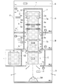
- the front schematic diagram which shows the whole structure of the glass plate manufacturing equipment which concerns on one Embodiment of this invention.
- the side surface schematic diagram which shows the whole structure of the glass plate manufacturing equipment which concerns on one Embodiment of this invention.
- a glass plate manufacturing facility 1 shown in FIGS. 1 and 2 is a facility for manufacturing a glass plate by an overflow downdraw method, and is disposed inside a building X.
- the glass plate manufacturing facility 1 includes a forming furnace 2, and the forming furnace 2 includes a formed body 3 for forming a glass ribbon G2 from molten glass G1.
- the molded body 3 is used for molding the glass ribbon G2 by the overflow down draw method, has a wedge-shaped cross-sectional shape, and supplies the molten glass G1 from above the molded body 3, and the molten glass G1 from the top.
- the glass ribbon G2 can be formed by overflowing the molten glass G1 and fusing the overflowed molten glass G1 at its lower end.
- the molding furnace 2 includes a plate drawing roller 2a, and the end portion in the width direction of the glass ribbon G2 fused at the lower end portion of the molded body 3 is clamped by a pair of plate drawing rollers 2a and 2a to form an ear portion. It is set as the structure shape
- the configuration in which the plate drawing roller 2a is provided in the molding furnace 2 is illustrated, but the plate drawing roller 2a may be provided in an annealing furnace to be described later.
- the glass plate manufacturing facility 1 includes an annealing furnace 4.
- the annealing furnace 4 is a furnace for gradually cooling and cooling the glass ribbon G2, and includes a slow cooling part 5 and a cooling part 6 in order from above.
- the glass ribbon G2 formed in the forming furnace 2 is sent to an annealing furnace 4 communicating with the lower end of the forming furnace 2.
- the glass plate manufacturing equipment 1 is set as the structure which covers the series conveyance path
- a series of booths 7 is constituted by the second booth 7b.
- the first booth 7a surrounds the slow cooling part 5 of the molding furnace 2 and the annealing furnace 4, is closed above the molding furnace 2, and the second booth 7b surrounds the cooling part 6 of the annealing furnace 4,
- the annealing furnace 4 is opened below the cooling unit 6. That is, the first booth 7a constitutes a part of the slow cooling part 5 of the molding furnace 2 and the annealing furnace 4, and the second booth 7b constitutes a part of the cooling part 6 of the annealing furnace 4. It is.
- the annealing portion 5 of the annealing furnace 4 is a portion for gradually cooling to remove the residual distortion of the glass ribbon G2, and includes a heater (not shown), adjusts the temperature in the booth 7, and the glass ribbon G2
- the glass ribbon G2 is conveyed vertically downward by the ceramic annealing roller 5a while adjusting the cooling rate.
- the cooling unit 6 of the annealing furnace 4 is a part for further sufficiently cooling the glass ribbon G2 that has been gradually cooled by the slow cooling unit 5, and while the glass ribbon G2 is allowed to cool, by a rubber support roller 6a, The glass ribbon G2 is conveyed vertically downward.
- the glass plate manufacturing facility 1 includes a cutting device 8.
- the glass ribbon G2 sufficiently cooled by the cooling unit 6 of the annealing furnace 4 is discharged downward from the lower end of the annealing furnace 4 and into a space (a cutting chamber C described later) communicating with the lower end of the annealing furnace 4. Sent.
- the glass plate manufacturing equipment 1 having such a configuration is arranged in the building X across a plurality of upper and lower floors.
- a slow cooling part 5 of the forming furnace 2 and the annealing furnace 4 is arranged in a forming slow cooling chamber A on the fourth floor of the building X, and the cooling part 6 of the annealing furnace 4 is 3 of the building X. It is arranged in the cooling room B on the floor.
- the installation floor number of the forming furnace 2 and the annealing furnace 4 (the slow cooling part 5 and the cooling part 6) shown in this embodiment is an example, and the structure of the glass plate manufacturing equipment 1 is arranged by the glass plate manufacturing equipment 1 It is not limited by the structure (number of floors) of the building X to be used and the number of installation floors of each part.
- the cutting device 8 is disposed in the cutting chamber C on the second floor of the building X, and the glass plate G3 cut into a predetermined length L by the cutting device 8 as shown in FIG.
- a step of transporting in the horizontal direction by a transport device (not shown) and further cutting to a predetermined width W by a cutting device (not shown) is provided on the same floor.
- the glass plate manufacturing facility 1 has a stacking room D for stacking glass to be discarded and glass to be reused on the first floor of the building X, and a defect occurs during cutting by the cutting device 8.
- Glass glass (referred to as defective glass G4) is dropped to the lower floor from the opening 9 formed immediately below the cutting device 8, so that the defective glass G4 can be easily accumulated in the accumulation room D on the first floor. It is configured.
- the opening 9 is provided with an opening / closing door (not shown) that is opened when the defective glass G4 is dropped and closed at other times.
- the glass plate manufacturing facility 1 includes an air conditioner 10.
- the air conditioner 10 is arrange
- the air conditioner 10 is a device for pressurizing the interior of the booth 7 (that is, a pressurizing device), and includes an air supply fan 11, a temperature control coil 12, and the like, and adjusts the air supply temperature of the air conditioner 10. It is configured to be able to.
- the air conditioner 10 may adjust the temperature of the outside air taken from the outside air duct 13 by the temperature control coil 12 and then supply the air inside the booth 7 via the air supply duct 14 to increase the atmospheric pressure in the booth 7. It is configured to be able to. It is agreed that the atmospheric pressure in the booth 7 will increase and the atmospheric pressure in the furnaces of the forming furnace 2 and annealing furnace 4 will increase.
- the glass plate manufacturing equipment 1 adjusts the temperature in the booth 7 by adjusting the temperature of the supply air according to the temperature of the outside air taken in from the outside air duct 13 by the temperature control coil 12 of the air conditioner 10, thereby achieving a chimney effect. It is comprised so that the air volume of the rising airflow which arises can be adjusted.
- the air conditioner 10 further includes a filter device 15.
- the filter device 15 is a device for filtering the air supplied into the booth 7 and increasing the cleanliness of the air.
- the glass plate manufacturing facility 1 is configured such that the outside air taken in from the outside air duct 13 by the air conditioner 10 can be supplied into the booth 7 after temperature adjustment and filtration.
- the glass plate manufacturing facility 1 employs a so-called HEPA filter as a filter constituting the filter device 15 and highly removes dust from the air supplied through the filter device 15. Can be maintained as clean as a clean room.
- the glass plate manufacturing equipment 1 pressurizes the inside of the booth 7 with the air conditioner 10, thereby comparing the pressure of the part corresponding to the annealing furnace 4 in the booth 7 to the pressure of the cutting chamber C in which the cutting device 8 is disposed. Thus, an air flow from the annealing furnace 4 toward the cutting chamber C is generated.
- the glass plate manufacturing facility 1 can suppress the rising air flow generated in the booth 7 by the chimney effect by supplying air into the booth 7 by the air conditioner 10, and further, dust is generated along with the rising air flow. Can be prevented from flowing into the booth 7 (annealing furnace 4) from the cutting chamber C, whereby the adhesion of foreign matter (particularly glass dust) to the glass ribbon G2 is more reliably suppressed.
- the glass plate manufacturing facility 1 communicates with a forming furnace 2 including a formed body 3 for forming a glass ribbon G2 by an overflow downdraw method, and a lower portion of the forming furnace 2,
- An annealing furnace 4 that gradually cools the glass ribbon G2 formed by the forming furnace 2 while being conveyed vertically downward, and a glass ribbon G2 that is disposed in a cutting chamber C that is a space communicating below the annealing furnace 4 is predetermined.
- the pressure inside the annealing furnace 4 ie, inside the booth 7) is increased to a pressure higher than the pressure in the cutting chamber C in which the cutting device 8 is disposed.
- an air conditioner 10 as a pressure device.
- the glass plate manufacturing equipment 1 invasion of foreign matters such as glass dust into the annealing furnace 4 can be prevented, and foreign matter can be prevented from adhering to the surface of the glass ribbon G2 during slow cooling, and has excellent surface quality.
- the glass plate G3 can be manufactured.
- the pressurizing device in the glass plate manufacturing facility 1 is an air conditioner 10 including an air supply fan 11, a temperature control coil 12, and a filter device 15. With such a configuration, glass dust is generated inside the annealing furnace 4. It can prevent more reliably that it adheres to the glass ribbon G2.
- the glass plate manufacturing facility 1 has a configuration in which an air supply duct 14 for sending air supply from the air conditioner 10 into the booth 7 is connected to the booth 7 corresponding to the annealing furnace 4 at a position below the support roller 6a. Among each part of the booth 7, the pressure in the second booth 7b closest to the cutting device 8 and corresponding to the cooling furnace 6 is made highest.
- the annealing furnace 4 gradually cools the glass ribbon G2 while adjusting the cooling rate while heating with a heater or the like in the slow cooling section 5, so that the first booth 7 a corresponding to the slow cooling section 5 is supplied with air. When the duct 14 is connected, the slow cooling rate may be disturbed.
- the air supply duct 14 is preferably connected to the second booth 7b corresponding to the cooling unit 6 rather than being connected to the first booth 7a corresponding to the slow cooling unit 5 of the annealing furnace 4, and More preferably, the booth 7b is connected to a portion closer to the cutting device 8.
- the annealing furnace 4 includes, in order from the upper side, a slow cooling part 5 that gradually cools the glass ribbon G2 formed by the forming furnace 2, and a cooling part that cools the slowly cooled glass ribbon G2.
- the slow cooling unit 5 includes an annealing roller 5a made of an inorganic material such as ceramic for transporting the glass ribbon G2 while cooling, and the cooling unit 6 cools the glass ribbon G2.
- a support roller 6a made of a heat-resistant resin material such as rubber for conveyance is provided, and an air supply duct 14 connected to the air conditioner 10 is below the support roller 6a, and the annealing furnace 4 (that is, the second).
- This configuration is connected to the booth 7b). With such a configuration, it is possible to increase the pressure of the cooling unit 6 in the annealing furnace 4, and to ensure that glass dust enters the annealing furnace 4 from the cutting chamber C. prevent Door can be.
- the glass plate manufacturing facility 1 further includes a pressure fan 20.
- the pressurizing fan 20 is a fan for pressurizing the inside of the forming slow cooling chamber A, and is connected to the forming slow cooling chamber A by an air supply duct 21, and the outside air taken in from the outside air duct 22 is converted into the forming slow cooling chamber.
- the inside of the molding annealing chamber A is pressurized.
- the glass plate manufacturing equipment 1 is suppressing the leak of the updraft from the booth 7 corresponding to the slow cooling part 5 of the forming furnace 2 and the annealing furnace 4 by pressurizing the inside of the forming slow cooling chamber A, Thereby, the air volume of the updraft flowing through the booth 7 is suppressed.
- the manufacturing method of the glass plate which concerns on one Embodiment of this invention is demonstrated.
- the manufacturing method of the glass plate which concerns on one Embodiment of this invention is a manufacturing method which manufactures the glass plate G3 using the glass plate manufacturing equipment 1.
- the inside of the booth 7 is pressurized with the air conditioner 10, and the atmospheric
- the pressure of each part of the glass plate manufacturing facility 1 if there is an exhaust fan (not shown) that exhausts air from the glass plate manufacturing facility 1, the exhaust amount of the exhaust fan is also adjusted. Also good.
- the difference between the atmospheric pressure of each part of the annealing furnace 4 (the slow cooling part 5 and the cooling part 6) and the atmospheric pressure of each room (the cutting room C and the accumulation room D) is represented by a symbol “+”. Expressed by the size of the number.
- the cooling unit 6 (high pressure side) and the cooling chamber B of the annealing furnace 4 are detected by the differential pressure gauge P1.
- the pressure difference with respect to the (low pressure side) is managed so that the inside of the cooling unit 6 has a positive pressure of about 2 Pa with respect to the cooling chamber B.
- the air conditioner 10 since the air conditioner 10 is pressurizing the cooling part 6, the inside of the cooling part 6 is 5 with respect to the cutting chamber C in the differential pressure gauge P2. It shows that the positive pressure is about 15 Pa.
- voltage of the annealing part 4 (low pressure side) and the cooling part 6 (high pressure side) of the annealing furnace 4 is managed with the differential pressure gauge P3.
- the inside of the cooling unit 6 is set to a positive pressure of about 0 to 3 Pa with respect to the slow cooling unit 5.
- voltage of the cooling part 6 (low pressure side) and the annealing annealing chamber A (high pressure side) of the annealing furnace 4 is managed with the differential pressure gauge P4.
- the forming slow cooling chamber A is set to a positive pressure of about 0 to 6 Pa with respect to the inside of the cooling unit 6.
- the differential pressure gauge P5 manages the differential pressure
- a positive pressure of about 1 to 5 Pa is applied to the accumulation chamber D.
- the cooling part 6 of the annealing furnace 4 is the slow cooling part 5 by managing the differential pressure
- FIG. thus, a positive pressure is surely applied to the cutting chamber C, so that the adhesion of foreign matter to the glass ribbon G2 is reliably suppressed.
- the method for manufacturing a glass plate according to an embodiment of the present invention is a method for manufacturing a glass plate G3 by an overflow downdraw method, and includes a forming furnace 2 including a formed body 3 for forming a glass ribbon G2.
- the furnace (in the booth 7) of the annealing furnace 4 that communicates with the lower part of the forming furnace 2 and gradually cools the glass ribbon G2 formed by the forming furnace 2 while being conveyed vertically downward is pressurized.
- the pressure in the forming furnace 2 and the annealing furnace 4 (in the booth 7) as compared to the pressure in the cutting chamber C in which the cutting device 8 for cutting the glass ribbon G2 into a predetermined length L is disposed. Is to raise.
- invasion of foreign materials, such as glass dust, into the annealing furnace 4 is prevented, and the glass ribbon G2 under slow cooling is prevented.
- a foreign material can be prevented from adhering to the surface, and a glass plate G3 having excellent surface quality can be manufactured.
- the air supply duct 14 constituting the glass plate manufacturing facility 1 is connected to the booth 7 at a position below the support roller 6 a of the annealing furnace 4.
- the pressure inside the annealing furnace 4 is set to be the highest at the part closest to the cutting device 8.
- the annealing furnace 4 is gradually cooled from the upper side, with the slow cooling part 5 for gradually cooling the glass ribbon G2 formed by the forming furnace 2.
- a cooling unit 6 for cooling the glass ribbon G2 includes an annealing roller 5a for transporting the glass ribbon G2 while gradually cooling, and the cooling unit 6 cools the glass ribbon G2.
- a support roller 6a is provided for transporting, and air is supplied into the annealing furnace 4 (in the second booth 7b) below the support roller 6a to pressurize the inside of the forming furnace 2 and the annealing furnace 4. Is.
- the pressure of the cooling unit 6 in the annealing furnace 4 can be increased, and glass dust can be reliably prevented from entering the annealing furnace 4 from the cutting chamber C.
- the manufacturing method of the glass plate which concerns on one Embodiment of this invention by adjusting the temperature of the air supplied in the booth 7 with the air conditioner 10, the upward airflow which arises in the booth 7 by a chimney effect is further suppressed.
- the annealing furnace 4 it is possible to more reliably prevent foreign matter (particularly glass dust) from adhering to the glass ribbon G2.
- the inside of the booth 7 is maintained by the cleanliness degree of a clean room by making the cleanliness of the air supplied into the booth 7 with the air conditioner 10 high.
- the adhesion of foreign matter (particularly glass dust) to the glass ribbon G2 in the annealing furnace 4 is more reliably suppressed.
- the air adjusted in temperature by the air conditioner 10 is supplied into the annealing furnace 4, and the air conditioner 10 includes the filter device 15.
- the air conditioner 10 includes the filter device 15.
- air with increased cleanliness is supplied through the filter device 15 by the air conditioner 10.
- the air supply amount of the pressurization fan 20 which comprises the glass plate manufacturing equipment 1 is adjusted, and this glass The pressure in the forming annealing chamber A of the plate manufacturing facility 1 is adjusted.
- the differential pressure between the forming annealing chamber A (high pressure side) and the tower E (low pressure side) is managed by the differential pressure gauge P6.
- the forming annealing chamber A is set to a positive pressure of about 20 to 30 Pa with respect to the tower E.
- the leak of the updraft from the booth 7 is suppressed by managing the differential pressure
- molding slow cooling chamber A with the pressurization fan 20, and a booth by the air conditioner 10 The quality of the glass plate G3 can be further improved by the synergistic effect of the surface quality improvement effect of the glass ribbon G2 obtained by pressurizing the inside 7.
- the forming annealing chamber A which is a space in which the forming furnace 2 and the annealing furnace 4 are arranged, is further pressurized.
- the upward air flow in the booth 7 can be suppressed, and consequently, the glass dust is prevented from adhering to the glass ribbon G2 inside the annealing furnace 4, and the shaking of the glass ribbon G2 is suppressed.
- the distortion of the glass ribbon G2 can be reduced.
- the case where the glass plate G3 is manufactured by the overflow downdraw method has been exemplified.
- the glass plate manufacturing method and the glass plate manufacturing facility according to the present invention are manufactured by the slot (slit) downdraw method.
- the present invention can also be applied when manufacturing.
- the glass plate manufacturing equipment and the glass plate manufacturing method according to the present invention can be widely applied when manufacturing various glass substrates for liquid crystal displays, plasma displays, electroluminescence displays, field emission displays, and the like. .
Landscapes
- Chemical & Material Sciences (AREA)
- Engineering & Computer Science (AREA)
- Materials Engineering (AREA)
- Organic Chemistry (AREA)
- Re-Forming, After-Treatment, Cutting And Transporting Of Glass Products (AREA)
Abstract
ガラス粉塵が切断室からアニール炉の内部に拡散することを防止して、優れた表面品質を有するガラス板を製造する。ガラス板製造設備1は、オーバーフローダウンドロー法によりガラスリボンG2を成形するための成形体3を備えた成形炉2と、成形炉2の下方に連通し、成形炉2により成形されたガラスリボンG2を、鉛直下方に搬送しつつ徐冷するアニール炉4と、アニール炉4の下方に連通する空間である切断室Cに配置される、ガラスリボンG2を所定の長さLに切断する切断装置8と、アニール炉4の内部(即ち、ブース7内)の気圧を、切断装置8が配置される切断室Cの気圧に比して高い気圧に加圧する空調機10と、を備える。
Description
本発明は、ダウンドロー法によるガラス板製造設備およびガラス板の製造方法の技術に関する。
近年、液晶ディスプレイの高精細化の要求等に対応するべく、ガラス板の表面品質の更なる向上が求められており、ガラス板を製造する際に、ガラス板の表面に異物が付着することを防止する必要性が高まっている。
このため従来、ガラス板の表面に異物が付着することを防止するための技術として、特許文献1、2に示すような技術が開発されている。
このため従来、ガラス板の表面に異物が付着することを防止するための技術として、特許文献1、2に示すような技術が開発されている。
特許文献1に示されているガラス板製造設備では、ガラスリボンを所定の寸法に切断してガラス基板を製造するための空間である切断室と、該切断室の下方に設けられた、廃棄ガラス基板を回収するための空間である回収室と、を備えており、回収室の気圧を切断室の気圧に比して低くする構成としている。
そして、特許文献1に示されているガラス板製造設備では、このような構成により、廃棄ガラス基板が割れる際に生じるガラス粉塵が、回収室から切断室へと拡散することを防止し、これにより、切断室においてガラス粉塵がガラス基板に付着することを防止している。
そして、特許文献1に示されているガラス板製造設備では、このような構成により、廃棄ガラス基板が割れる際に生じるガラス粉塵が、回収室から切断室へと拡散することを防止し、これにより、切断室においてガラス粉塵がガラス基板に付着することを防止している。
また、特許文献2に示されているガラス板製造設備では、ガラスリボンを切断するための空間であるガラスリボン切断空間と、切断されたガラスリボンから耳部を切断するための空間である耳部切断空間と、を備えており、ガラスリボン切断空間の気圧が耳部切断空間の気圧に比して高くなるように、ガラスリボン切断空間および耳部切断空間の少なくとも何れか一方の気圧を調整する構成としている。
そして、特許文献2に示されているガラス板製造設備では、このような構成により、ガラスリボンから耳部を切断する際に生じたガラス粉塵が、ガラスリボン切断空間に侵入し、ガラスリボンに付着することを防止している。
そして、特許文献2に示されているガラス板製造設備では、このような構成により、ガラスリボンから耳部を切断する際に生じたガラス粉塵が、ガラスリボン切断空間に侵入し、ガラスリボンに付着することを防止している。
ガラス板製造設備では、成形炉とアニール炉が竪穴状のブースによって連通されており、ブース内で煙突効果による上昇気流が生じるため、ガラスリボンを切断する際に生じるガラス粉塵が、アニール炉の下方に位置する切断室から上昇気流に乗ってアニール炉の内部に拡散することが懸念されていた。
しかしながら、特許文献1、2に係る従来技術では、切断室においてガラスリボンを切断する際に生じるガラス粉塵が、切断室からアニール炉の内部に拡散することは防止できなかった。
しかしながら、特許文献1、2に係る従来技術では、切断室においてガラスリボンを切断する際に生じるガラス粉塵が、切断室からアニール炉の内部に拡散することは防止できなかった。
本発明は、斯かる現状の課題に鑑みてなされたものであり、ガラス粉塵が切断室からアニール炉の内部に拡散することを防止して、優れた表面品質を有するガラス板を製造することができるガラス板製造設備およびガラス板の製造方法を提供することを目的としている。
本発明の解決しようとする課題は以上の如くであり、次にこの課題を解決するための手段を説明する。
即ち、本願の第1の発明に係るガラス板製造設備は、ダウンドロー法によりガラスリボンを成形するための成形体を備えた成形炉と、前記成形炉の下方に連通し、前記成形炉により成形された前記ガラスリボンを、鉛直下方に搬送しつつ徐冷するアニール炉と、前記アニール炉の下方に連通する空間に配置される、前記ガラスリボンを所定の寸法に切断する切断装置と、前記アニール炉の内部の気圧を、前記切断装置が配置される空間の気圧に比して高い気圧に加圧する加圧装置と、を備えることを特徴とする。
また、本願の第2の発明に係るガラス板製造設備において、前記アニール炉は、上方側から順に、前記成形炉により成形された前記ガラスリボンを徐冷する徐冷部と、徐冷した前記ガラスリボンを冷却する冷却部と、を備え、前記徐冷部は、前記ガラスリボンを徐冷しつつ搬送するためのアニールローラを備えており、前記冷却部は、前記ガラスリボンを冷却しつつ搬送するための支持ローラを備えており、前記加圧装置は、前記支持ローラよりも下方で、前記アニール炉に接続されることを特徴とする。
このような構成により、アニール炉のうち冷却部の気圧を高めることができ、切断室からアニール炉にガラス粉塵が侵入することを確実に防ぐことができる。
このような構成により、アニール炉のうち冷却部の気圧を高めることができ、切断室からアニール炉にガラス粉塵が侵入することを確実に防ぐことができる。
また、本願の第3の発明に係るガラス板製造設備において、前記加圧装置は、給気ファンと温調コイルとフィルタ装置を備えた空調機であることを特徴とする。
このような構成により、アニール炉の内部でガラス粉塵がガラスリボンに付着することをより確実に防ぐことができる。
このような構成により、アニール炉の内部でガラス粉塵がガラスリボンに付着することをより確実に防ぐことができる。
また、本願の第4の発明に係るガラス板の製造方法は、ダウンドロー法によるガラス板製造方法であって、ガラスリボンを成形するための成形体を備えた成形炉と、前記成形炉の下方に連通し、前記成形炉により成形された前記ガラスリボンを鉛直下方に搬送しつつ徐冷するアニール炉、の炉内を加圧して、前記アニール炉の下方に連通し、前記ガラスリボンを所定の寸法に切断する切断装置が配置される空間の気圧に比して、前記成形炉と前記アニール炉内の気圧を高くすることを特徴とする。
また、本願の第5の発明に係るガラス板の製造方法において、前記アニール炉は、上方側から順に、前記成形炉により成形された前記ガラスリボンを徐冷する徐冷部と、徐冷した前記ガラスリボンを冷却する冷却部と、を備え、前記徐冷部は、前記ガラスリボンを徐冷しつつ搬送するためのアニールローラを備えており、前記冷却部は、前記ガラスリボンを冷却しつつ搬送するための支持ローラを備えており、前記支持ローラよりも下方で前記アニール炉内に給気して、前記成形炉内と前記アニール炉内を加圧することを特徴とする。
このような構成により、アニール炉のうち冷却部の気圧を高めることができ、切断室からアニール炉にガラス粉塵が侵入することを確実に防ぐことができる。
このような構成により、アニール炉のうち冷却部の気圧を高めることができ、切断室からアニール炉にガラス粉塵が侵入することを確実に防ぐことができる。
また、本願の第6の発明に係るガラス板の製造方法は、前記アニール炉内に、空調機によって温度調整された空気を給気することを特徴とする。
このような構成により、アニール炉の内部でガラス粉塵がガラスリボンに付着することをより確実に防ぐことができる。
このような構成により、アニール炉の内部でガラス粉塵がガラスリボンに付着することをより確実に防ぐことができる。
また、本願の第7の発明に係るガラス板の製造方法においては、前記空調機はフィルタ装置を備えており、前記アニール炉内に、前記空調機によって、前記フィルタ装置を通して清浄度を高めた前記空気を給気することを特徴とする。
このような構成により、アニール炉の内部でガラス粉塵がガラスリボンに付着することをより確実に防ぐことができる。
このような構成により、アニール炉の内部でガラス粉塵がガラスリボンに付着することをより確実に防ぐことができる。
また、本願の第8の発明に係るガラス板の製造方法においては、さらに、前記成形炉と前記アニール炉が配置された空間を加圧することを特徴とする。
このような構成により、上昇気流を抑制することができ、ひいては、アニール炉の内部でガラス粉塵がガラスリボンに付着することを防ぐとともに、ガラスリボンの揺れを抑制し、歪みの低減を図ることができる。
このような構成により、上昇気流を抑制することができ、ひいては、アニール炉の内部でガラス粉塵がガラスリボンに付着することを防ぐとともに、ガラスリボンの揺れを抑制し、歪みの低減を図ることができる。
本発明の効果として、以下に示すような効果を奏する。
本発明に係るガラス板製造設備およびガラス板の製造方法は、アニール炉へのガラス粉塵等の異物の侵入が防止され、徐冷中のガラスリボンの表面に異物が付着することを防止できる。これにより、優れた表面品質を有するガラス板を製造することができる。
次に、本発明の実施の形態を説明する。
まず、本発明の一実施形態に係るガラス板製造設備について説明する。
図1および図2に示すガラス板製造設備1は、オーバーフローダウンドロー法によりガラス板を製造する設備であり、建屋Xの内部に配置されている。
ガラス板製造設備1は、成形炉2を備えており、成形炉2は、溶融ガラスG1からガラスリボンG2を成形するための成形体3を備えている。
まず、本発明の一実施形態に係るガラス板製造設備について説明する。
図1および図2に示すガラス板製造設備1は、オーバーフローダウンドロー法によりガラス板を製造する設備であり、建屋Xの内部に配置されている。
ガラス板製造設備1は、成形炉2を備えており、成形炉2は、溶融ガラスG1からガラスリボンG2を成形するための成形体3を備えている。
成形体3は、オーバーフローダウンドロー法によるガラスリボンG2の成形に用いるものであり、楔状の断面形状を有しており、該成形体3の上方から溶融ガラスG1を供給し、頂部から溶融ガラスG1を溢れ出させるとともに、溢れ出た溶融ガラスG1をその下端部で融合させることによって、ガラスリボンG2を成形することができるものである。
また、成形炉2は、板引きローラ2aを備えており、成形体3の下端部で融合されたガラスリボンG2の幅方向端部を一対の板引きローラ2a・2aで挟圧して、耳部を備えた所定の形状に成形する構成としている。尚、本実施形態では、成形炉2において板引きローラ2aが備えられる構成を例示しているが、板引きローラ2aは、後述するアニール炉に備えられる構成であっても良い。
また、ガラス板製造設備1は、アニール炉4を備えている。
アニール炉4は、ガラスリボンG2を徐冷および冷却するための炉であり、上方から順に、徐冷部5と冷却部6を備えている。
成形炉2において成形されたガラスリボンG2は、該成形炉2の下端に連通するアニール炉4へと送られる。
アニール炉4は、ガラスリボンG2を徐冷および冷却するための炉であり、上方から順に、徐冷部5と冷却部6を備えている。
成形炉2において成形されたガラスリボンG2は、該成形炉2の下端に連通するアニール炉4へと送られる。
そして、ガラス板製造設備1は、成形炉2からアニール炉4へと繋がるガラスリボンG2の一連の搬送経路を竪穴状のブース7で覆う構成としており、上端側の第一ブース7aと下端側の第二ブース7bによって、一連のブース7を構成している。第一ブース7aは、成形炉2とアニール炉4の徐冷部5を囲っており、成形炉2の上方において閉塞され、第二ブース7bは、アニール炉4の冷却部6を囲っており、アニール炉4の冷却部6下方において開放されている。
即ち、第一ブース7aは、成形炉2とアニール炉4の徐冷部5の一部を構成するものであり、第二ブース7bは、アニール炉4の冷却部6の一部を構成するものである。
即ち、第一ブース7aは、成形炉2とアニール炉4の徐冷部5の一部を構成するものであり、第二ブース7bは、アニール炉4の冷却部6の一部を構成するものである。
アニール炉4の徐冷部5は、ガラスリボンG2の残留歪みを除去するべく徐冷するための部位であり、図示しないヒータ等を備えており、ブース7内の温度を調整し、ガラスリボンG2の冷却速度を調整しつつ、セラミック製のアニールローラ5aによって、鉛直下方にガラスリボンG2を搬送する。
アニール炉4の冷却部6は、徐冷部5で徐冷されたガラスリボンG2をさらに十分に冷却するための部位であり、ガラスリボンG2を放冷させつつ、ゴム製の支持ローラ6aによって、鉛直下方にガラスリボンG2を搬送する。
また、ガラス板製造設備1は、切断装置8を備えている。
アニール炉4の冷却部6で十分に冷却されたガラスリボンG2は、アニール炉4の下端から下方に向けて排出され、該アニール炉4の下端に連通する空間(後述する切断室C)へと送られる。
アニール炉4の冷却部6で十分に冷却されたガラスリボンG2は、アニール炉4の下端から下方に向けて排出され、該アニール炉4の下端に連通する空間(後述する切断室C)へと送られる。
このような構成のガラス板製造設備1は、建屋Xの内部において上下複数の階に跨って配置されている。
ガラス板製造設備1は、成形炉2とアニール炉4の徐冷部5が建屋Xの4階の成形徐冷室Aに配置されており、アニール炉4の冷却部6は、建屋Xの3階の冷却室Bに配置されている。
尚、本実施形態で示した成形炉2およびアニール炉4(徐冷部5、冷却部6)の設置階数は例示であり、ガラス板製造設備1の構成は、該ガラス板製造設備1が配置される建屋Xの構造(階数)および各部位の設置階数によっては限定されない。
ガラス板製造設備1は、成形炉2とアニール炉4の徐冷部5が建屋Xの4階の成形徐冷室Aに配置されており、アニール炉4の冷却部6は、建屋Xの3階の冷却室Bに配置されている。
尚、本実施形態で示した成形炉2およびアニール炉4(徐冷部5、冷却部6)の設置階数は例示であり、ガラス板製造設備1の構成は、該ガラス板製造設備1が配置される建屋Xの構造(階数)および各部位の設置階数によっては限定されない。
ガラス板製造設備1は、切断装置8が建屋Xの2階の切断室Cに配置されており、図2に示すように、切断装置8で所定の長さLに切断されたガラス板G3を図示しない搬送装置によって水平方向に搬送して、さらに図示しない切断装置によって所定の幅Wに切断する工程が同じ階に設けられている。
さらに、ガラス板製造設備1は、建屋Xの1階において、廃棄するガラスや再利用するガラスを集積するための集積室Dを配置しており、切断装置8による切断の際等に不良が生じたガラス(不良ガラスG4と呼ぶ)を、切断装置8の直下に形成した開口部9から下階に落下させることで、不良ガラスG4を1階の集積室Dに容易に集積することができるように構成している。尚、開口部9には、不良ガラスG4を落下させるときに開とし、その他のときは閉とする図示しない開閉扉を設けている。
さらに、ガラス板製造設備1は、空調機10を備えている。尚、本実施形態では、空調機10を建屋Xの2階に配置した場合を例示しているが、ガラス板製造設備1における空調機10の配置はこれに限定されない。
空調機10は、ブース7の内部を加圧するための装置(即ち、加圧装置)であり、給気ファン11、温調コイル12等を備えており、空調機10の給気温度を調整することができるように構成している。空調機10は、外気ダクト13から取り入れた外気を温調コイル12によって温度調整した後に、給気ダクト14を介してブース7の内部に給気して、ブース7内の気圧を上昇させることができるように構成している。尚、ブース7内の気圧が上昇することと、成形炉2およびアニール炉4の炉内の気圧が上昇することは同意である。
ガラス板製造設備1は、空調機10の温調コイル12によって、外気ダクト13から取り入れる外気の温度に応じて給気温度を調整することにより、ブース7内の温度を調整して、煙突効果に起因して生じる上昇気流の風量を調整することができるように構成している。
また、空調機10は、フィルタ装置15をさらに備えている。
フィルタ装置15は、ブース7内に給気する空気を濾過して、該空気の清浄度を高めるための装置である。
ガラス板製造設備1は、空調機10によって外気ダクト13から取り入れた外気を、温度調整および濾過した後に、ブース7内に給気することができるように構成している。
フィルタ装置15は、ブース7内に給気する空気を濾過して、該空気の清浄度を高めるための装置である。
ガラス板製造設備1は、空調機10によって外気ダクト13から取り入れた外気を、温度調整および濾過した後に、ブース7内に給気することができるように構成している。
また、ガラス板製造設備1では、フィルタ装置15を構成するフィルタとして所謂HEPAフィルタを採用しており、フィルタ装置15を介して給気される空気から高度に粉塵を除去しており、ブース7内をクリーンルーム並みの清浄度に維持することができる構成としている。
さらに、ガラス板製造設備1は、空調機10でブース7内を加圧することによって、ブース7におけるアニール炉4に対応する部位の気圧を、切断装置8の配置された切断室Cの気圧に比して高くしており、これにより、アニール炉4から切断室Cに向かう気流を生じさせるようにしている。
また、ガラス板製造設備1は、空調機10によってブース7内に給気を行うことにより、煙突効果によってブース7内で生じる上昇気流も抑制することができ、さらに、その上昇気流に伴って粉塵が切断室Cからブース7内(アニール炉4)へ流入するのを抑制することができ、これにより、ガラスリボンG2への異物(特にガラス粉塵)の付着がより確実に抑制される。
即ち、本発明の一実施形態に係るガラス板製造設備1は、オーバーフローダウンドロー法によりガラスリボンG2を成形するための成形体3を備えた成形炉2と、成形炉2の下方に連通し、成形炉2により成形されたガラスリボンG2を、鉛直下方に搬送しつつ徐冷するアニール炉4と、アニール炉4の下方に連通する空間である切断室Cに配置される、ガラスリボンG2を所定の長さLに切断する切断装置8と、アニール炉4の内部(即ち、ブース7内)の気圧を、切断装置8が配置される切断室Cの気圧に比して高い気圧に加圧する加圧装置たる空調機10と、を備えるものである。
そして、ガラス板製造設備1によれば、アニール炉4へのガラス粉塵等の異物の侵入が防止され、徐冷中のガラスリボンG2の表面に異物が付着することを防止でき、優れた表面品質を有するガラス板G3を製造することができる。
また、ガラス板製造設備1における加圧装置は、給気ファン11と温調コイル12とフィルタ装置15を備えた空調機10であり、このような構成により、アニール炉4の内部でガラス粉塵がガラスリボンG2に付着することをより確実に防ぐことができる。
ガラス板製造設備1は、空調機10の給気をブース7内に送り込む給気ダクト14を、支持ローラ6aよりも下方の位置で、アニール炉4に対応するブース7に接続する構成としており、ブース7の各部のうち、切断装置8に最も近く冷却炉6に対応する第二ブース7b内の気圧が最も高くなるようにしている。
尚、アニール炉4は、徐冷部5において、ヒータ等で加熱しながら冷却速度を調整しつつガラスリボンG2を徐冷しているため、徐冷部5に対応する第一ブース7aに給気ダクト14を接続すると、徐冷速度が乱れる恐れがある。このため、給気ダクト14は、アニール炉4の徐冷部5に対応する第一ブース7aに接続するよりも冷却部6に対応する第二ブース7bに接続することが好ましく、さらに、第二ブース7bのうち切断装置8により近い部位に接続することがより好ましい。
尚、アニール炉4は、徐冷部5において、ヒータ等で加熱しながら冷却速度を調整しつつガラスリボンG2を徐冷しているため、徐冷部5に対応する第一ブース7aに給気ダクト14を接続すると、徐冷速度が乱れる恐れがある。このため、給気ダクト14は、アニール炉4の徐冷部5に対応する第一ブース7aに接続するよりも冷却部6に対応する第二ブース7bに接続することが好ましく、さらに、第二ブース7bのうち切断装置8により近い部位に接続することがより好ましい。
即ち、ガラス板製造設備1において、アニール炉4は、上方側から順に、成形炉2により成形されたガラスリボンG2を徐冷する徐冷部5と、徐冷したガラスリボンG2を冷却する冷却部6と、を備え、徐冷部5は、ガラスリボンG2を徐冷しつつ搬送するためのセラミック等の無機材料製のアニールローラ5aを備えており、冷却部6は、ガラスリボンG2を冷却しつつ搬送するためのゴム等の耐熱樹脂材料製の支持ローラ6aを備えており、空調機10に接続された給気ダクト14は、支持ローラ6aよりも下方で、アニール炉4(即ち、第二ブース7b)に接続されるものであり、このような構成により、アニール炉4のうち冷却部6の気圧を高めることができ、切断室Cからアニール炉4にガラス粉塵が侵入することを確実に防ぐことができる。
また、本発明の一実施形態に係るガラス板製造設備1は、さらに加圧ファン20を備えている。
加圧ファン20は、成形徐冷室A内を加圧するためのファンであり、給気ダクト21によって成形徐冷室Aに接続されており、外気ダクト22から取り入れた外気を、成形徐冷室A内に給気することで、成形徐冷室A内を加圧するように構成している。
そして、ガラス板製造設備1は、成形徐冷室A内を加圧することによって、成形炉2およびアニール炉4の徐冷部5に対応するブース7からの上昇気流の漏れを抑制しており、これにより、ブース7内を流れる上昇気流の風量を抑制している。
加圧ファン20は、成形徐冷室A内を加圧するためのファンであり、給気ダクト21によって成形徐冷室Aに接続されており、外気ダクト22から取り入れた外気を、成形徐冷室A内に給気することで、成形徐冷室A内を加圧するように構成している。
そして、ガラス板製造設備1は、成形徐冷室A内を加圧することによって、成形炉2およびアニール炉4の徐冷部5に対応するブース7からの上昇気流の漏れを抑制しており、これにより、ブース7内を流れる上昇気流の風量を抑制している。
本発明の一実施形態に係るガラス板の製造方法について説明する。
本発明の一実施形態に係るガラス板の製造方法は、ガラス板製造設備1を用いてガラス板G3を製造する製造方法である。
本発明の一実施形態に係るガラス板の製造方法は、ガラス板製造設備1を用いてガラス板G3を製造する製造方法である。
本発明の一実施形態に係るガラス板の製造方法では、図1および図2に示すように、ガラス板製造設備1を構成する空調機10でブース7内を加圧することによって、アニール炉4の気圧を、切断装置8の配置された切断室Cの気圧に比して高くしており、これにより、アニール炉4から切断室Cに向かう気流を生じさせるようにしている。
そして、本発明の一実施形態に係るガラス板の製造方法では、空調機10によってブース7内を加圧することにより、煙突効果によってブース7内で生じる上昇気流を抑制しており、上昇気流に伴って粉塵が切断室Cからブース7内へ流入することを抑制することができ、これにより、アニール炉4においてガラスリボンG2へ異物(特にガラス粉塵)が付着することを確実に抑制するようにしている。
そして、本発明の一実施形態に係るガラス板の製造方法では、ブース7のうち、アニール炉4の冷却部6に対応する第二ブース7bにおいて、アニール炉4内の気圧を最も高くするようにしており、これにより、切断室Cで生じたガラス粉塵が、アニール炉4内に流入することを抑制するようにしている。さらに、本発明の一実施形態に係るガラス板の製造方法では、第二ブース7bのうち、切断装置8に最も近い部位において、アニール炉4内の気圧を最も高くするようにしており、これにより、切断室Cで生じたガラス粉塵が、アニール炉4内に流入することをより確実に抑制するようにしている。
また、本発明の一実施形態に係るガラス板の製造方法では、空調機10によって、ブース7内を加圧して、該ガラス板製造設備1の各部位の気圧が、気圧の高い側から順に冷却部6、徐冷部5、切断室C、集積室Dとなるようにしている。尚、ガラス板製造設備1の各部位の気圧の調整に際しては、該ガラス板製造設備1から排気を行う図示しない排気ファンが存在する場合には、当該排気ファンの排気量を併せて調整してもよい。また、ここでは説明の便宜上、アニール炉4の各部(徐冷部5および冷却部6)の気圧と各部屋(切断室Cおよび集積室D)の気圧の高低差を、「+」の記号の個数の大小で表している。
具体的には、図1、2に示すように、本発明の一実施形態に係るガラス板G3の製造方法では、差圧計P1によって、アニール炉4の冷却部6(高圧側)と冷却室B(低圧側)との差圧を管理して、冷却部6内が冷却室Bに対して2Pa程度の陽圧となるようにしている。
また、本発明の一実施形態に係るガラス板G3の製造方法では、空調機10が冷却部6を加圧しているため、差圧計P2は、冷却部6内が切断室Cに対して、5~15Pa程度の陽圧となることを示している。
また、本発明の一実施形態に係るガラス板G3の製造方法では、差圧計P3によって、アニール炉4の徐冷部5(低圧側)と冷却部6(高圧側)の差圧を管理して、冷却部6内が徐冷部5に対して0~3Pa程度の陽圧となるようにしている。
また、本発明の一実施形態に係るガラス板G3の製造方法では、差圧計P4によって、アニール炉4の冷却部6(低圧側)と成形徐冷室A(高圧側)の差圧を管理して、成形徐冷室Aが冷却部6内に対して0~6Pa程度の陽圧となるようにしている。
また、本発明の一実施形態に係るガラス板G3の製造方法では、差圧計P5によって、切断室C(高圧側)と集積室D(低圧側)の差圧を管理して、切断室Cが集積室Dに対して1~5Pa程度の陽圧となるようにしている。
このように、本発明の一実施形態に係るガラス板G3の製造方法では、ガラス板製造設備1の各部位の差圧を管理することで、アニール炉4の冷却部6が、徐冷部5と切断室Cに対して確実に陽圧となるようにしており、これにより、ガラスリボンG2に対する異物の付着を確実に抑制するようにしている。
即ち、本発明の一実施形態に係るガラス板の製造方法は、オーバーフローダウンドロー法によるガラス板G3の製造方法であって、ガラスリボンG2を成形するための成形体3を備えた成形炉2と、成形炉2の下方に連通し、成形炉2により成形されたガラスリボンG2を鉛直下方に搬送しつつ徐冷するアニール炉4、の炉内(ブース7内)を加圧して、アニール炉4の下方に連通し、ガラスリボンG2を所定の長さLに切断する切断装置8が配置される切断室Cの気圧に比して、成形炉2とアニール炉4内(ブース7内)の気圧を高くするものである。
そして、本発明の一実施形態に係るガラス板製造設備1を用いたガラス板G3の製造方法によれば、アニール炉4へのガラス粉塵等の異物の侵入が防止され、徐冷中のガラスリボンG2の表面に異物が付着することを防止でき、優れた表面品質を有するガラス板G3を製造することができる。
また、本発明の一実施形態に係るガラス板の製造方法では、ガラス板製造設備1を構成する給気ダクト14を、アニール炉4の支持ローラ6aよりも下方の位置で、ブース7に接続しており、アニール炉4の各部のうち、切断装置8に最も近い部位において、アニール炉4内部の気圧が最も高くなるようにしている。
即ち、本発明の一実施形態に係るガラス板の製造方法において、アニール炉4は、上方側から順に、成形炉2により成形されたガラスリボンG2を徐冷する徐冷部5と、徐冷したガラスリボンG2を冷却する冷却部6と、を備え、徐冷部5は、ガラスリボンG2を徐冷しつつ搬送するためのアニールローラ5aを備えており、冷却部6は、ガラスリボンG2を冷却しつつ搬送するための支持ローラ6aを備えており、支持ローラ6aよりも下方でアニール炉4内(第二ブース7b内)に給気して、成形炉2内とアニール炉4内を加圧するものである。
このような構成により、アニール炉4のうち冷却部6の気圧を高めることができ、切断室Cからアニール炉4にガラス粉塵が侵入することを確実に防ぐことができる。
このような構成により、アニール炉4のうち冷却部6の気圧を高めることができ、切断室Cからアニール炉4にガラス粉塵が侵入することを確実に防ぐことができる。
また、本発明の一実施形態に係るガラス板の製造方法では、空調機10によってブース7内に給気する空気の温度を調整することにより、煙突効果によってブース7内で生じる上昇気流をさらに抑制しており、アニール炉4においてガラスリボンG2へ異物(特にガラス粉塵)が付着することをより確実に抑制するようにしている。
さらに、本発明の一実施形態に係るガラス板の製造方法では、空調機10によってブース7内に給気する空気の清浄度を高くすることにより、ブース7内をクリーンルーム程度の清浄度に維持して、アニール炉4におけるガラスリボンG2へ異物(特にガラス粉塵)の付着をより確実に抑制するようにしている。
さらに、本発明の一実施形態に係るガラス板の製造方法では、空調機10によってブース7内に給気する空気の清浄度を高くすることにより、ブース7内をクリーンルーム程度の清浄度に維持して、アニール炉4におけるガラスリボンG2へ異物(特にガラス粉塵)の付着をより確実に抑制するようにしている。
即ち、本発明の一実施形態に係るガラス板の製造方法においては、アニール炉4内に、空調機10によって温度調整された空気を給気するものであり、空調機10はフィルタ装置15を備えており、アニール炉4内に、空調機10によって、フィルタ装置15を通して清浄度を高めた空気を給気するものである。
このような構成により、アニール炉4の内部でガラス粉塵がガラスリボンG2に付着することをより確実に防ぐことができる。
このような構成により、アニール炉4の内部でガラス粉塵がガラスリボンG2に付着することをより確実に防ぐことができる。
また、本発明の一実施形態に係るガラス板の製造方法では、図1および図2に示すように、ガラス板製造設備1を構成する加圧ファン20の給気量を調整して、該ガラス板製造設備1の成形徐冷室Aの気圧を調整している。
具体的には、本発明の一実施形態に係るガラス板G3の製造方法では、差圧計P6によって、成形徐冷室A(高圧側)と塔屋E(低圧側)の差圧を管理して、成形徐冷室Aが塔屋Eに対して20~30Pa程度の陽圧となるようにしている。
本発明の一実施形態に係るガラス板の製造方法では、成形徐冷室A(高圧側)と塔屋E(低圧側)の差圧を管理することで、ブース7からの上昇気流の漏れを抑制している。
そして、本発明の一実施形態に係るガラス板の製造方法では、成形炉2およびアニール炉4内の上昇気流の風量を抑制することで、アニール炉4におけるガラスリボンG2の揺れを抑制することができ、ひいては、揺れに起因して生じるガラスリボンG2の歪みを抑制することができる。
そして、本発明の一実施形態に係るガラス板の製造方法では、成形炉2およびアニール炉4内の上昇気流の風量を抑制することで、アニール炉4におけるガラスリボンG2の揺れを抑制することができ、ひいては、揺れに起因して生じるガラスリボンG2の歪みを抑制することができる。
このように、本発明の一実施形態に係るガラス板の製造方法では、加圧ファン20で成形徐冷室Aを加圧することにより得られるガラスリボンG2の歪み低減効果と、空調機10によってブース7内を加圧することにより得られるガラスリボンG2の表面品質向上効果の相乗効果によって、ガラス板G3の品質をより向上させることができる。
即ち、本発明の一実施形態に係るガラス板の製造方法においては、さらに、成形炉2とアニール炉4が配置された空間である成形徐冷室Aを加圧するものである。
このような構成により、ブース7内の上昇気流を抑制することができ、ひいては、アニール炉4の内部でガラス粉塵がガラスリボンG2に付着することを防ぐとともに、ガラスリボンG2の揺れを抑制して、ガラスリボンG2の歪みを低減することができる。
このような構成により、ブース7内の上昇気流を抑制することができ、ひいては、アニール炉4の内部でガラス粉塵がガラスリボンG2に付着することを防ぐとともに、ガラスリボンG2の揺れを抑制して、ガラスリボンG2の歪みを低減することができる。
尚、本実施形態では、オーバーフローダウンドロー法によりガラス板G3を製造する場合を例示したが、本発明に係るガラス板の製造方法およびガラス板製造設備は、スロット(スリット)ダウンドロー法によりガラス板を製造する場合にも適用することができる。
本発明に係るガラス板製造設備およびガラス板の製造方法は、液晶ディスプレイ用、プラズマディスプレイ用、エレクトロルミネッセンスディスプレイ用、フィールドエミッションディスプレイ用等の種々のガラス基板を製造する場合に広く適用することができる。
1 ガラス板製造設備
2 成形炉
3 成形体
4 アニール炉
5 徐冷部
5a アニールローラ
6 冷却部
6a 支持ローラ
7 ブース
8 切断装置
10 空調機
11 給気ファン
12 温調コイル
13 外気ダクト
14 給気ダクト
15 フィルタ装置
A 成形徐冷室
B 冷却室
C 切断室
X 建屋
G2 ガラスリボン
G3 ガラス板
2 成形炉
3 成形体
4 アニール炉
5 徐冷部
5a アニールローラ
6 冷却部
6a 支持ローラ
7 ブース
8 切断装置
10 空調機
11 給気ファン
12 温調コイル
13 外気ダクト
14 給気ダクト
15 フィルタ装置
A 成形徐冷室
B 冷却室
C 切断室
X 建屋
G2 ガラスリボン
G3 ガラス板
Claims (8)
- ダウンドロー法によりガラスリボンを成形するための成形体を備えた成形炉と、
前記成形炉の下方に連通し、前記成形炉により成形された前記ガラスリボンを、鉛直下方に搬送しつつ徐冷するアニール炉と、
前記アニール炉の下方に連通する空間に配置される、前記ガラスリボンを所定の寸法に切断する切断装置と、
前記アニール炉の内部の気圧を、
前記切断装置が配置される空間の気圧に比して高い気圧に加圧する加圧装置と、
を備える、
ことを特徴とするガラス板製造設備。 - 前記アニール炉は、
上方側から順に、
前記成形炉により成形された前記ガラスリボンを徐冷する徐冷部と、
徐冷した前記ガラスリボンを冷却する冷却部と、
を備え、
前記徐冷部は、
前記ガラスリボンを徐冷しつつ搬送するためのアニールローラを備えており、
前記冷却部は、
前記ガラスリボンを冷却しつつ搬送するための支持ローラを備えており、
前記加圧装置は、
前記支持ローラよりも下方で、前記アニール炉に接続される、
ことを特徴とする請求項1に記載のガラス板製造設備。 - 前記加圧装置は、
給気ファンと温調コイルとフィルタ装置を備えた空調機である、
ことを特徴とする請求項1または請求項2に記載のガラス板製造設備。 - ダウンドロー法によるガラス板製造方法であって、
ガラスリボンを成形するための成形体を備えた成形炉と、前記成形炉の下方に連通し、前記成形炉により成形された前記ガラスリボンを鉛直下方に搬送しつつ徐冷するアニール炉、の炉内を加圧して、
前記アニール炉の下方に連通し、前記ガラスリボンを所定の寸法に切断する切断装置が配置される空間の気圧に比して、前記成形炉と前記アニール炉内の気圧を高くする、
ことを特徴とするガラス板の製造方法。 - 前記アニール炉は、
上方側から順に、
前記成形炉により成形された前記ガラスリボンを徐冷する徐冷部と、
徐冷した前記ガラスリボンを冷却する冷却部と、
を備え、
前記徐冷部は、
前記ガラスリボンを徐冷しつつ搬送するためのアニールローラを備えており、
前記冷却部は、
前記ガラスリボンを冷却しつつ搬送するための支持ローラを備えており、
前記支持ローラよりも下方で前記アニール炉内に給気して、前記成形炉内と前記アニール炉内を加圧する、
ことを特徴とする請求項4に記載のガラス板の製造方法。 - 前記アニール炉内に、
空調機によって温度調整された空気を給気する、
ことを特徴とする請求項4または請求項5に記載のガラス板の製造方法。 - 前記空調機はフィルタ装置を備えており、
前記アニール炉内に、
前記空調機によって、前記フィルタ装置を通して清浄度を高めた前記空気を給気する、
ことを特徴とする請求項6に記載のガラス板の製造方法。 - さらに、
前記成形炉と前記アニール炉が配置された空間を加圧する、
ことを特徴とする請求項4~請求項7の何れか一項に記載のガラス板の製造方法。
Priority Applications (2)
| Application Number | Priority Date | Filing Date | Title |
|---|---|---|---|
| KR1020187027970A KR102132982B1 (ko) | 2016-02-29 | 2017-02-21 | 유리판 제조설비 및 유리판의 제조방법 |
| CN201780013942.5A CN108698877B (zh) | 2016-02-29 | 2017-02-21 | 玻璃板制造设备及玻璃板的制造方法 |
Applications Claiming Priority (2)
| Application Number | Priority Date | Filing Date | Title |
|---|---|---|---|
| JP2016037430A JP6623836B2 (ja) | 2016-02-29 | 2016-02-29 | ガラス板製造設備およびガラス板の製造方法 |
| JP2016-037430 | 2016-02-29 |
Publications (1)
| Publication Number | Publication Date |
|---|---|
| WO2017150266A1 true WO2017150266A1 (ja) | 2017-09-08 |
Family
ID=59743884
Family Applications (1)
| Application Number | Title | Priority Date | Filing Date |
|---|---|---|---|
| PCT/JP2017/006287 Ceased WO2017150266A1 (ja) | 2016-02-29 | 2017-02-21 | ガラス板製造設備およびガラス板の製造方法 |
Country Status (4)
| Country | Link |
|---|---|
| JP (1) | JP6623836B2 (ja) |
| KR (1) | KR102132982B1 (ja) |
| CN (1) | CN108698877B (ja) |
| WO (1) | WO2017150266A1 (ja) |
Cited By (3)
| Publication number | Priority date | Publication date | Assignee | Title |
|---|---|---|---|---|
| JP2020045267A (ja) * | 2018-09-21 | 2020-03-26 | 日本電気硝子株式会社 | ガラス板の製造方法 |
| KR20200119780A (ko) | 2018-02-13 | 2020-10-20 | 니폰 덴키 가라스 가부시키가이샤 | 유리 기판군 및 그 제조 방법 |
| KR20230098818A (ko) | 2020-11-04 | 2023-07-04 | 니폰 덴키 가라스 가부시키가이샤 | 유리 기판 및 전자 디바이스의 제조 방법 |
Families Citing this family (5)
| Publication number | Priority date | Publication date | Assignee | Title |
|---|---|---|---|---|
| WO2020090627A1 (ja) * | 2018-11-01 | 2020-05-07 | 日本電気硝子株式会社 | ガラス板の製造方法および製造装置 |
| CN118723245A (zh) * | 2019-12-10 | 2024-10-01 | 日本电气硝子株式会社 | 玻璃板的制造方法 |
| CN114555536B (zh) * | 2019-12-18 | 2024-02-13 | 日本电气硝子株式会社 | 玻璃物品的制造方法以及玻璃物品的制造装置 |
| JP7675324B2 (ja) * | 2021-04-09 | 2025-05-13 | 日本電気硝子株式会社 | ガラス板の製造装置、及びガラス板の製造方法 |
| JP2025529209A (ja) * | 2022-08-31 | 2025-09-04 | コーニング インコーポレイテッド | ガラスリボンを製造するための方法及び装置 |
Citations (3)
| Publication number | Priority date | Publication date | Assignee | Title |
|---|---|---|---|---|
| JP2009173525A (ja) * | 2007-12-25 | 2009-08-06 | Nippon Electric Glass Co Ltd | ガラス板の製造方法及び製造設備 |
| JP2011136847A (ja) * | 2009-12-25 | 2011-07-14 | Asahi Glass Co Ltd | フロートガラス製造装置の冷却レア |
| JP2014125363A (ja) * | 2012-12-25 | 2014-07-07 | Avanstrate Inc | ガラス基板製造装置及びディスプレイ用ガラス基板の製造方法 |
Family Cites Families (5)
| Publication number | Priority date | Publication date | Assignee | Title |
|---|---|---|---|---|
| JP4621996B2 (ja) | 2007-04-24 | 2011-02-02 | 日本電気硝子株式会社 | ガラス板製造方法およびガラス板製造設備 |
| WO2012026136A1 (ja) * | 2010-08-27 | 2012-03-01 | AvanStrate株式会社 | ガラス基板の製造装置およびガラス基板の製造方法 |
| CN103253848B (zh) * | 2011-06-30 | 2016-08-17 | 安瀚视特控股株式会社 | 玻璃板的制造方法及玻璃板的制造装置 |
| KR101269870B1 (ko) | 2011-10-28 | 2013-06-07 | 이미지랩(주) | 액티브 리타드 패널 및 이를 구비하는 나노 액정층 기반의 입체영상 표시장치 |
| JP5782058B2 (ja) * | 2013-02-21 | 2015-09-24 | AvanStrate株式会社 | ガラスシートの製造方法、ガラスシート製造装置、及びガラス積層体 |
-
2016
- 2016-02-29 JP JP2016037430A patent/JP6623836B2/ja active Active
-
2017
- 2017-02-21 CN CN201780013942.5A patent/CN108698877B/zh active Active
- 2017-02-21 KR KR1020187027970A patent/KR102132982B1/ko active Active
- 2017-02-21 WO PCT/JP2017/006287 patent/WO2017150266A1/ja not_active Ceased
Patent Citations (3)
| Publication number | Priority date | Publication date | Assignee | Title |
|---|---|---|---|---|
| JP2009173525A (ja) * | 2007-12-25 | 2009-08-06 | Nippon Electric Glass Co Ltd | ガラス板の製造方法及び製造設備 |
| JP2011136847A (ja) * | 2009-12-25 | 2011-07-14 | Asahi Glass Co Ltd | フロートガラス製造装置の冷却レア |
| JP2014125363A (ja) * | 2012-12-25 | 2014-07-07 | Avanstrate Inc | ガラス基板製造装置及びディスプレイ用ガラス基板の製造方法 |
Cited By (4)
| Publication number | Priority date | Publication date | Assignee | Title |
|---|---|---|---|---|
| KR20200119780A (ko) | 2018-02-13 | 2020-10-20 | 니폰 덴키 가라스 가부시키가이샤 | 유리 기판군 및 그 제조 방법 |
| JP2020045267A (ja) * | 2018-09-21 | 2020-03-26 | 日本電気硝子株式会社 | ガラス板の製造方法 |
| WO2020059391A1 (ja) * | 2018-09-21 | 2020-03-26 | 日本電気硝子株式会社 | ガラス板の製造方法 |
| KR20230098818A (ko) | 2020-11-04 | 2023-07-04 | 니폰 덴키 가라스 가부시키가이샤 | 유리 기판 및 전자 디바이스의 제조 방법 |
Also Published As
| Publication number | Publication date |
|---|---|
| KR20180117169A (ko) | 2018-10-26 |
| JP2017154911A (ja) | 2017-09-07 |
| CN108698877A (zh) | 2018-10-23 |
| CN108698877B (zh) | 2021-01-08 |
| KR102132982B1 (ko) | 2020-07-10 |
| JP6623836B2 (ja) | 2019-12-25 |
Similar Documents
| Publication | Publication Date | Title |
|---|---|---|
| JP6623836B2 (ja) | ガラス板製造設備およびガラス板の製造方法 | |
| JP4621996B2 (ja) | ガラス板製造方法およびガラス板製造設備 | |
| CN103124701B (zh) | 玻璃板的制造方法及玻璃板制造装置 | |
| US8322160B2 (en) | Process and apparatus for producing glass sheet | |
| US8322161B2 (en) | Process and apparatus for producing glass sheet | |
| CN103228584B (zh) | 浮法平板玻璃的制造装置及浮法平板玻璃的制造方法 | |
| CN103261106A (zh) | 玻璃板的制造方法及玻璃板制造装置 | |
| JP2018090448A (ja) | 板ガラスの製造方法 | |
| JP6536427B2 (ja) | フロートガラスの製造装置、フロートガラスの製造方法 | |
| WO2017002626A1 (ja) | ガラス基板の製造方法及びガラス基板製造装置 | |
| JP7415252B2 (ja) | ガラス物品の製造方法 | |
| TW201609573A (zh) | 片狀玻璃之製造方法及片狀玻璃製造裝置 | |
| KR102685759B1 (ko) | 유리 물품의 제조 방법 및 유리 물품의 제조 장치 | |
| JP2023105659A (ja) | ガラス物品の製造方法 | |
| JP2017014062A (ja) | ガラス基板の製造方法、およびガラス基板 | |
| JP6587844B2 (ja) | ディスプレイ用ガラス板の製造方法、および、ディスプレイ用ガラス板製造装置 | |
| JP6082434B2 (ja) | ガラス基板の製造方法及びガラス基板 | |
| JP6690980B2 (ja) | ガラス基板の搬送方法、ガラス基板搬送装置 | |
| CN121778966A (zh) | 成形体以及玻璃物品的制造方法 | |
| TWI580650B (zh) | Glass substrate manufacturing method and glass substrate | |
| JP2010243098A (ja) | ガラス基板の温度慣らし装置 | |
| JP2017014050A (ja) | ガラス基板の製造方法 |
Legal Events
| Date | Code | Title | Description |
|---|---|---|---|
| NENP | Non-entry into the national phase |
Ref country code: DE |
|
| ENP | Entry into the national phase |
Ref document number: 20187027970 Country of ref document: KR Kind code of ref document: A |
|
| 121 | Ep: the epo has been informed by wipo that ep was designated in this application |
Ref document number: 17759732 Country of ref document: EP Kind code of ref document: A1 |
|
| 122 | Ep: pct application non-entry in european phase |
Ref document number: 17759732 Country of ref document: EP Kind code of ref document: A1 |