WO2017150177A1 - ケース体およびこれを備えたルーバー装置 - Google Patents
ケース体およびこれを備えたルーバー装置 Download PDFInfo
- Publication number
- WO2017150177A1 WO2017150177A1 PCT/JP2017/005343 JP2017005343W WO2017150177A1 WO 2017150177 A1 WO2017150177 A1 WO 2017150177A1 JP 2017005343 W JP2017005343 W JP 2017005343W WO 2017150177 A1 WO2017150177 A1 WO 2017150177A1
- Authority
- WO
- WIPO (PCT)
- Prior art keywords
- case
- motor
- arm
- link
- lock piece
- Prior art date
- Legal status (The legal status is an assumption and is not a legal conclusion. Google has not performed a legal analysis and makes no representation as to the accuracy of the status listed.)
- Ceased
Links
Images




Classifications
-
- F—MECHANICAL ENGINEERING; LIGHTING; HEATING; WEAPONS; BLASTING
- F16—ENGINEERING ELEMENTS AND UNITS; GENERAL MEASURES FOR PRODUCING AND MAINTAINING EFFECTIVE FUNCTIONING OF MACHINES OR INSTALLATIONS; THERMAL INSULATION IN GENERAL
- F16B—DEVICES FOR FASTENING OR SECURING CONSTRUCTIONAL ELEMENTS OR MACHINE PARTS TOGETHER, e.g. NAILS, BOLTS, CIRCLIPS, CLAMPS, CLIPS OR WEDGES; JOINTS OR JOINTING
- F16B5/00—Joining sheets or plates, e.g. panels, to one another or to strips or bars parallel to them
- F16B5/07—Joining sheets or plates, e.g. panels, to one another or to strips or bars parallel to them by means of multiple interengaging protrusions on the surfaces, e.g. hooks, coils
-
- F—MECHANICAL ENGINEERING; LIGHTING; HEATING; WEAPONS; BLASTING
- F24—HEATING; RANGES; VENTILATING
- F24F—AIR-CONDITIONING; AIR-HUMIDIFICATION; VENTILATION; USE OF AIR CURRENTS FOR SCREENING
- F24F13/00—Details common to, or for air-conditioning, air-humidification, ventilation or use of air currents for screening
- F24F13/08—Air-flow control members, e.g. louvres, grilles, flaps or guide plates
- F24F13/10—Air-flow control members, e.g. louvres, grilles, flaps or guide plates movable, e.g. dampers
- F24F13/14—Air-flow control members, e.g. louvres, grilles, flaps or guide plates movable, e.g. dampers built up of tilting members, e.g. louvre
-
- H—ELECTRICITY
- H02—GENERATION; CONVERSION OR DISTRIBUTION OF ELECTRIC POWER
- H02K—DYNAMO-ELECTRIC MACHINES
- H02K7/00—Arrangements for handling mechanical energy structurally associated with dynamo-electric machines, e.g. structural association with mechanical driving motors or auxiliary dynamo-electric machines
- H02K7/10—Structural association with clutches, brakes, gears, pulleys or mechanical starters
- H02K7/116—Structural association with clutches, brakes, gears, pulleys or mechanical starters with gears
Definitions
- the present invention relates to a case body and a louver device including the same.
- an arm that supports a wind direction plate (louver 5) along an arcuate cam surface (guide surface 322e) provided in a case (second cases 312 and 322).
- a louver device (louver device 1) is disclosed in which an arm is reciprocated between a retracted position and an advanced position by sliding a cam follower portion (arc portions 213, 223) of a second louver support member 22). ing.
- the louver device of Patent Document 1 moves the arm that supports the wind direction plate to the forward position, and rotates the wind direction plate away from the air conditioner body. Therefore, in the louver device of Patent Document 1, the arm is easily touched by the user's eyes, and the arm is required to have high design.
- the locking portions of these case members are provided at positions that are visible to the user. And there exists a subject that this exposed latching part impairs the design property of an arm.
- the louver device of Patent Document 1 when the arm is moved to the forward movement position, the load of the arm and the wind direction plate is applied to the base end portion of the arm and the case (the first fixed body 31 and the second fixed body 32). It is necessary to support only in the vicinity of the opening.
- one of the arms (first louver support member 21) is provided with a motor (second motor 81) for rotating the wind direction plate at the tip thereof, and further the wind pressure received by the wind direction plate. Also increase the load.
- second motor 81 for rotating the wind direction plate at the tip thereof, and further the wind pressure received by the wind direction plate.
- the problem to be solved by the present invention is to provide a case body whose design property is improved by providing a locking portion of the case member invisible from the outside, and a wind direction plate including the case body.
- Another object of the present invention is to provide a louver device capable of supporting the load of an arm in a distributed manner.
- a case body of the present invention includes a first case member and a second case member that are fitted to each other, and an inner surface of the first case member has a distal end with the inner surface as a base end.
- a lock piece that is a protrusion protruding inside the first case member is formed, and a lock hole that is a through hole that engages with the lock piece is formed in the second case member,
- the thickness of the lock piece in the fitting direction of the first case member to the second case member is formed so that the distal end side is thinner than the proximal end side, and the lock piece extends from the proximal end to the distal end.
- the length is a length penetrating the lock hole when the first case member and the second case member are fitted together.
- the lock piece is set to a size that does not penetrate the lock hole. This is because if the lock piece penetrates the lock hole, the tip of the lock piece may damage the contents in the case. Since the lock hole of the present invention is arranged inside the case body rather than the lock piece, for example, when the contents in the case are approaching the vicinity of the lock hole, the displacement of the lock hole to the inside of the case is limited. The If a hook with a normal height is used in this situation, the tip of the lock piece rides on the edge of the lock hole, and the case body may not be locked no matter how much the case body is fitted.
- the lock piece of the present invention is intentionally set to a length (height) penetrating the lock hole, the amount of deformation of the first case member when fitting the case body is increased, and the lock piece is locked. It will be strongly pressed against the hole. Furthermore, since the lock piece of the present invention is shaped so that the tip is thinner than the base end, the tip of the lock piece is easily bent. As a result, the case body of the present invention can avoid the problem that the lock piece easily enters the lock hole and the case body is not locked even when the displacement of the lock hole to the inside of the case is restricted. ing.
- the first case member is elastic in the height direction of the lock piece. It is preferably made of a flexible material that can be deformed.
- the first case member is preferably made of a resin material.
- a spacer member that is housed together with the motor in the case of the case body and fixes the position of the motor in the case, and the direction along the axial direction of the motor is a vertical direction in the case.
- the spacer member fixes the vertical position of the motor in the case by pressing the end surface on the output shaft side of the motor, and the motor is cylindrical from the end surface along the outer peripheral surface of the output shaft.
- the spacer member has a bearing fixing hole that is a through hole into which the bearing portion of the motor is press-fitted, and the outer peripheral surface of the motor in the case is formed in the spacer member.
- a gap is preferably provided around the periphery.
- the motor has a high molding accuracy in the space inside the motor case, it is expected that errors on the outer surface of the motor case will appear larger than the inner surface due to variations in the thickness of the individual motor case. Therefore, when positioning the motor inside the case body, for example, by supporting the outer peripheral surface of the motor case, the motor may not fit in the case body, or the motor may rattle on the contrary.
- the case body of this configuration is provided with a separate spacer member for positioning the motor in the case, and the vertical position of the motor in the case is fixed using the spacer member, and the error is smaller than the outer peripheral surface of the motor case.
- the spacer member has a fixed circumferential angle and radial position in the case, and the motor is a motor having a support shaft that is a rod-like body extending perpendicularly from the end surface. Is formed with a support shaft fixing hole, which is a through hole into which the support shaft of the motor is press-fitted, and the motor has the bearing portion of the motor in the bearing fixing hole of the spacer member. It is preferable that the circumferential angle and the radial position in the case are fixed by press-fitting each of the support shafts into the support shaft fixing holes of the spacer member.
- a louver device of the present invention includes a first drive source, a link mechanism that swings by the drive force of the first drive source, and a fixing portion that can accommodate the link mechanism.
- the link mechanism includes an arm member having the case body according to any one of claims 1 to 5, and a plurality of the support members that support the arm member and reciprocate the arm member in the extending direction and the storing direction.
- the link members include a drive link driven by the first drive source, and a driven link that follows the operation of the drive link via the arm member.
- the drive link has a distal end side connected to the arm member, a proximal end side connected to the first drive source directly or via another member, and the driven link has a distal end side connected to the arm member.
- Proximal side The is coupled to the fixed portion, the extending direction side end portion of the arm member, characterized in that the wind direction plate is a plate-shaped member is pivotally connected.
- the load of the wind direction plate and the arm member can be distributed to each link member by reciprocating the arm member that opens and closes the wind direction plate by the link mechanism. As a result, it is possible to prevent the stress supporting the load from concentrating on only a part, and to reduce the size of the entire apparatus.
- the link mechanism is a four-bar link mechanism having the arm member as an intermediate link, and the driven link is disposed on the extension direction side with respect to the drive link.
- the link mechanism a four-bar link
- the reciprocating movement of the arm member by the link mechanism can be realized with a minimum number of parts.
- the driven link does not need to be connected to the first drive source, there are fewer restrictions on the arrangement location than the drive link. Therefore, by disposing the driven link closer to the extending direction of the arm member than the driving link, the driven link can be disposed at the end of the extending direction side of the device, and the arm member is supported farther. Is possible.
- a second drive source is disposed at a side end portion of the arm member in the extending direction, and the wind direction plate is rotatable within a predetermined angle range by a drive force of the second drive source. Is preferred.
- Rotating the wind direction plate by the second drive source provided at the side end portion in the extending direction of the arm member enables more complicated operation of the wind direction plate, and the degree of freedom of wind direction control can be increased.
- the second drive source is preferably a stepping motor.
- the stepping motor can rotate in both forward and reverse directions, and the rotation angle can be calculated from the number of steps. Therefore, it is not necessary to separately perform feedback control using a rotary encoder or the like in order to detect the arrangement angle of the wind direction plate at that time. Thereby, the number of parts in the whole apparatus can be reduced and the apparatus can be downsized.
- the design of the case body can be improved, and the load of the wind direction plate and the arm can be dispersed and supported.
- louver device is a device that is installed at a blower opening of an air conditioner (not shown) and controls the air direction.
- width direction means the X direction shown in the coordinate axis display of FIG. 1
- front-back direction means the Y direction shown in the coordinate axis display
- vertical direction means the same coordinate axis table.
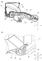
- FIG. 1 is an external perspective view showing an example of an arrangement configuration of a louver device.
- one common wind direction plate 91 is also referred to as two louver devices 10, 10 ′ and one support unit 70 (hereinafter collectively referred to as “louver device 10 etc.”). ).
- the two louver devices 10 and 10 ' are the same device, and the configuration of the louver device 10 described below is also the configuration of the louver device 10'.
- These louver devices 10 and the like are all arranged behind the wind direction plate 91 (on the side of the air conditioner casing not shown).
- the louver devices 10 and 10 ′ are arranged in the vicinity of both ends in the longitudinal direction of the wind direction plate 91, and the support unit 70 is arranged at substantially the center in the longitudinal direction.
- Arm connection pieces 911 and 912 which are connecting portions with the louver device 10 and the like are formed on the surface of the wind direction plate 91 facing the louver device 10 and the like.
- the wind direction plate 91 is supported by the arms 42 and 72 by coupling the arm connection pieces 911 and 912 to the wind direction plate connection portions 262 and 721 provided on the arms 42 and 72 of the louver device 10 and the like.
- the arms 42 and 72 operate integrally.
- the louver device 10, 10 ' is a drive device that opens and closes and rotates the wind direction plate 91 by the driving force of the drive source provided in the louver device 10, 10'.
- the support unit 70 is an auxiliary unit that supports the wind direction plate 91 following the operation of the louver devices 10, 10 ′. Even when the length of the wind direction plate 91 in the longitudinal direction is short, or when only the both ends of the wind direction plate 91 are supported by the louver devices 10 and 10 ′, the wind direction plate 91 has a rigidity that does not cause deflection due to its own weight. In some cases, the support unit 70 may be omitted.
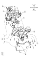
- FIG. 2 is an exploded perspective view showing the internal structure of the louver device 10 (and the louver device 10 ′).
- the louver device 10 includes a first motor 20 (first drive source) that is a stepping motor, a link mechanism 40 that swings by the driving force of the first motor 20, and a link mechanism 40 that decelerates the rotation of the first motor 20. And a case 50 (fixed portion) that accommodates the link mechanism 40 and the reduction gear train 30.
- the link mechanism 40 includes two link members 41 and an arm 42 (arm member) supported by these link members 41 and reciprocating in an extension direction A and a storage direction B (see FIG. 6) described later. ing.
- the link member 41 includes a drive link 411 driven by the first motor 20 and a driven link 412 that follows the operation of the drive link 411 via the arm 42.
- the link mechanism 40 constitutes a four-bar linkage mechanism in which the case 50 is a fixed link and the arm 42 is an intermediate link.
- the case 50 includes a first case half 51 that can be disassembled in the width direction X, a second case half 52, and an intermediate plate 53.
- the first case half 51, the second case half 52, and the intermediate plate 53 are integrated by being connected by a set screw 59.
- the link mechanism 40 is disposed in a space defined by the first case half 51 and the middle plate 53, and the reduction gear train 30 is disposed in a space defined by the second case half 52 and the middle plate 53.
- the first motor 20 is disposed outside the bottom surface (surface orthogonal to the width direction X) of the second case half 52 and is fixed to the second case half 52 by a set screw 29.
- a portion corresponding to the position of the pinion gear 21 of the first motor 20 has a covered cylindrical shape protruding toward the opening side (inside the case 50) of the second case half 52.
- the pinion cover part 521 is provided.
- the pinion cover portion 521 is open on the pinion gear 21 side, and the pinion gear 21 is accommodated inside the pinion cover portion 521.
- the pinion cover part 521 is provided with a window part 521a which is an opening partly cut off in the circumferential direction, and the pinion gear 21 housed in the pinion cover part 521 has a part of its tooth part. Is exposed to the inside of the second case half 52 from the window 521a.
- the reduction gear train 30 is a composite gear train that includes a large-diameter gear portion and a small-diameter gear portion, respectively. Each gear member of the reduction gear train 30 is rotatably supported by a support shaft 36 erected between the second case half 52 and the intermediate plate 53.
- the reduction gear train 30 sequentially transmits the rotation of the pinion gear 21 of the first motor 20 from the large diameter gear portion to the small diameter gear portion, thereby reducing the rotation of the pinion gear 21 and transmitting it to the gear portion 411c of the drive link 411. To do.
- the arm 42 can be reciprocated using a general output motor.
- a through hole 411b penetrating in the width direction X is formed in the base end portion (base end side) of the drive link 411 constituting the link mechanism 40, and the support shaft erected in the second case half 52 By inserting 522 into the through hole 411b, the base end portion of the drive link 411 is rotatably supported by the case 50.
- a gear portion 411c extending toward the reduction gear train 30 side is provided at the base end portion of the drive link 411.
- a cutout portion 533 through which the gear portion 411c is inserted is formed at a portion corresponding to the position of the gear portion 411c in the intermediate plate 53.
- the gear portion 411 c is inserted through the notch portion 533, thereby penetrating the intermediate plate 53 and meshing with the final gear of the reduction gear train 30.
- the driving force of the first motor 20 is transmitted to the drive link 411 via the reduction gear train 30 and the gear portion 411c.
- the driven link 412 of the link mechanism 40 is provided with a substantially cylindrical shaft body 412b whose axis is parallel to the width direction X at the base end portion (base end side). Bearings 513 and 523 which are circular through holes penetrating in the width direction X are formed at portions corresponding to the positions of the shaft bodies 412 b in the first case half 51 and the second case half 52.
- the driven link 412 is rotatably supported by the case 50 by fitting the shaft body 412b to the bearings 513 and 523.
- the “base end” of the link member 41 (drive link 411, driven link 412) in the present invention is a fixed joint, that is, fixed to a predetermined position and allowed to rotate, but in the vertical direction Z and the front-rear direction Y.
- the “tip” refers to a free joint, that is, an end that is allowed to rotate and swing.
- the base ends of the drive link 411 and the driven link 412 are both supported by the case 50, but these base ends need not necessarily be supported by the case 50.
- a member (fixed part) whose position is fixed such as a housing of an air conditioner (not shown), can support the base end part rotatably, and is deformed by the load of the arm 42 and the wind direction plate 91
- the case 50 can be substituted if it is a member having such a degree of rigidity that it does not.
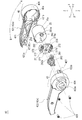
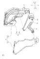
- FIG. 3 is an exploded perspective view showing the internal structure of the arm 42.
- the arm 42 includes an arm case 42 a that is a case body of the arm 42.
- the arm case 42a includes a first arm half 421 that is a first case member fitted in the width direction X, and a second arm half 422 that is a second case member.
- a hook portion 426 and a lock hole 427 are provided at the ends of the first arm half body 421 and the second arm half body 422 on the extending direction A side to lock the fitted end portions, respectively.
- the first arm half 421 and the second arm half 422 are fixed by the hook portion 426 and the lock hole 427 and the three set screws 429.
- a motor chamber 43 in which the second motor 25 that is the second drive source is accommodated is provided at the end portion in the extending direction A side of the arm case 42a and in the vicinity thereof.
- the second motor 25 is a stepping motor that rotates the wind direction plate 91 within a predetermined angle range.
- a pinion gear 261 is attached to the output shaft 253 of the second motor 25 where the D cut is applied.
- a wind direction plate connecting portion 262 is rotatably supported on a support shaft 252 (described later) that is fixed to the second motor 25 so as not to move and extends parallel to the axial direction of the output shaft 253.
- the rotation of the pinion gear 261 is decelerated via the gear portion 262 a of the wind direction plate connecting portion 262 and transmitted to the wind direction plate connecting portion 262.
- the relative positional relationship of the wind direction plate connecting portion 262 with respect to the output shaft 253 is kept constant. I'm leaning.
- the meshing accuracy of the pinion gear 261 and the gear portion 262a of the wind direction plate connecting portion 262 is increased, and noises due to rattling of these gear members and a decrease in component life are suppressed.
- a circular opening 422a penetrating in the width direction X is formed at a portion of the second arm half 422 constituting the motor chamber 43, and the wind direction plate connecting portion 262 is connected to the outside of the arm case 42a from the opening 422a. Is exposed. Thereby, the wind direction plate connection part 262 of the arm 42 and the arm connection piece 911 of the wind direction plate 91 can be coupled.
- a corrugated rib 423 is provided in a portion closer to the storage direction B than the motor chamber 43, and the rigidity of the arm case 42 a is enhanced by the rib 423.
- a part of the rib 423 also serves as an arm-side contact portion 67 of the second swing restricting portion 65 described later.
- FIG. 8 is a diagram for explaining a structure for handling the lead wire 93 of the second motor 25.
- the lead wire 93 connected to the connector 259 of the second motor 25 is drawn into the case 50 through a gap provided above the rib 423 inside the arm 42.
- the lead wire 93 drawn into the case 50 passes through the upper side of the drive link 411 and is drawn into the guide piece 532 formed on the rear side (left side in FIG. 8) of the intermediate plate 53 and guided to the guide piece 532. It is pulled out of the louver device 10 from the outlet 54.
- the outlet 54 is an opening defined by the first case half 51 and the second case half 52.
- a spacer member 27 that fixes the position of the second motor 25 in the motor chamber 43 is accommodated together with the second motor 25.
- the spacer member 27 includes a substantially disc-shaped flat plate portion 271 and a pair of side plate portions 272 extending from the periphery of the flat plate portion 271 to the second motor 25 side.
- the pair of side plate portions 272 are formed at positions and ranges that are line-symmetrical at the periphery of the flat plate portion 271.
- the direction along the axial direction of the second motor 25 is the vertical direction inside the motor chamber 43 (the first arm half 421 side is “down”, the second arm half is The body 422 side is referred to as “upper.”
- “upper” and “lower” refer to the same vertical direction
- the flat plate portion 271 of the spacer member 27 Is placed on the upper surface 251 that is the end surface of the second motor 25 on the output shaft 253 side, and the upper surface 251 is pressed downward to fix the vertical position of the second motor 25 in the motor chamber 43.
- the pair of side plate portions 272 are not in contact with the inner peripheral surface of the second arm half 422 and the outer peripheral surface 25a of the second motor 25, and a gap is provided between them. Further, the outer peripheral surface 25a of the second motor 25 and the inner peripheral surface 43a of the motor chamber 43 are not in contact with each other, and a gap is provided between them.
- Two substantially cylindrical anti-rotation sleeves 273 extending toward the second arm half 422 are formed on the surface of the flat plate portion 271 of the spacer member 27 on the second arm half 422 side.
- Each anti-rotation sleeve 273 is provided with a slit in a part of its circumferential direction, so that it can be elastically deformed radially outward.
- a detent pin 424 which is a protrusion fitted to each detent sleeve 273, is formed at a position corresponding to the position where each detent sleeve 273 is formed. Yes.
- the spacer member 27 is fitted in the rotation-preventing pin 424 and the rotation-preventing sleeve 273 so that the spacer member 27 has a circumferential angle and a radial position in the motor chamber 43 (a position in a direction perpendicular to the vertical direction. The same applies to the above).
- a bearing portion 251 a extending in a cylindrical shape from the upper surface 251 along the outer peripheral surface of the output shaft 253 is formed, and at a position corresponding to the position where the bearing portion 251 a is formed in the flat plate portion 271.
- a support shaft 252, which is a rod-like body extending perpendicularly from the upper surface 251, is fixed to the upper surface 251 of the second motor 25 so as not to move, and at a position corresponding to the position where the support shaft 252 is formed in the flat plate portion 271.
- a support shaft fixing hole 271b which is a through hole into which the support shaft 252 is press-fitted, is formed. As described above, the position and angle of the spacer member 27 in the motor chamber 43 are fixed.
- the second motor 25 has a bearing portion 251 a that is press-fitted into the bearing fixing hole 271 a of the spacer member 27 and a support shaft 252 that is press-fitted into the support shaft fixing hole 271 b of the spacer member 27.
- the circumferential angle and the radial position in the motor chamber 43 are fixed. That is, the absolute position of the second motor 25 in the motor chamber 43 is fixed.
- the motor has a high molding accuracy in the space inside the motor case, it is expected that the outer surface of the motor case has a larger error than the inner surface due to variations in the thickness of the individual motor case. Therefore, when positioning the motor inside the case body, for example, by supporting the outer peripheral surface of the motor case, the motor may not fit in the case body, or on the contrary, the motor may rattle. .
- the motor chamber 43 of the present embodiment covers the spacer member 27 separately provided in the motor chamber 43 on the upper surface 251 of the second motor 25 while providing a gap around the outer peripheral surface 25a of the second motor 25, thereby reducing the molding error.
- the second motor 25 is absorbed while absorbing an error appearing on the outer surface of the second motor 25. It is possible to suppress noise and a decrease in component life due to 25 rattles.
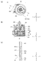
- FIG. 12 is an explanatory diagram of a locking structure of the arm case 42a using the hook portion 426 and the lock hole 427.
- FIG. 12A is a plan view of the arm 42 as viewed from the second arm half body 422 side
- FIG. 12B is a cross-sectional view in the CC direction of FIG. 12A
- FIG. 12C is FIG. It is an enlarged view of the part enclosed with the broken line D of b).
- the hook portion 426 is a protruding portion with the distal end protruding inside the motor chamber 43 with the inner peripheral surface 43 a of the motor chamber 43 of the first arm half 421 as the base end.
- the second arm half 422 has a tongue-like stopper portion 422c at a position corresponding to the position where the hook portion 426 is formed, and the stopper portion 422c has a lock that is a through hole that engages with the hook portion 426.
- a hole 427 is formed.
- the hook portion 426 and the lock hole 427 are a pair of lock pieces and a lock hole that latch the end portion on the extending direction A side of the arm case 42a. Since the hook portion 426 and the lock hole 427 are arranged inside the arm case 42a, they are concealed from the outside, and the design of the arm case 42a is enhanced.
- the hook portion 426 in the fitting direction of the first arm half body 421 and the second arm half body 422 (in the width direction X in the present embodiment) is formed so that the distal end side is thinner than the proximal end side. ing. More specifically, the hook portion 426 is formed as a tapered surface 426a whose surface corresponding to the upper surface of the hook portion 426 in FIG. 12C gradually decreases from the base end toward the tip end.
- a tapered surface on which the tapered surface 426a of the hook portion 426 rides when the first arm half body 421 and the second arm half body 422 are fitted is formed at the distal end portion of the stopper portion 422c.
- the first arm half body 421 is elastically deformed in the height direction of the hook portion 426 by about the height of the hook portion 426. It is made of a resin material capable of.
- the height of the hook portion 426 in this embodiment is a height that penetrates the lock hole 427.
- the lock piece is set to a size that does not penetrate the lock hole. This is because if the lock piece penetrates the lock hole, the tip of the lock piece may damage the contents in the case.
- the lock hole 427 of this embodiment is disposed inside the motor chamber 43 with respect to the hook portion 426. Further, the outer peripheral surface 25a of the motor 25 approaches the vicinity of the stopper portion 422c in which the lock hole 427 is formed, and the displacement of the lock hole 427 into the motor chamber 43 is limited.
- the tip of the lock piece rides on the edge of the lock hole, and the case body may not be locked no matter how much the case body is fitted.
- the hook portion 426 of the present embodiment is intentionally set to a height penetrating the lock hole 427, the amount of deformation of the first arm half 421 when the arm case 42a is fitted increases, and the hook portion 426 is strongly pressed against the lock hole 427. Furthermore, since the hook portion 426 of the present embodiment is shaped so that the tip thickness is thinner than the base end thereof, the tip of the hook portion 426 is easily bent.
- the hook portion 426 is easily pushed into the lock hole 427 while the displacement of the lock hole 427 (stopper portion 422c) into the motor chamber 43 is limited. It is possible to avoid the problem that the arm case 42a is not locked.
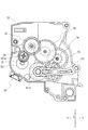
- FIG. 4 is a transparent view showing the meshing structure of the reduction gear train 30.
- the tooth part shown by the dotted line in FIG. 4 represents the gear part on the rear side of the figure of each gear member.
- the tooth part of the pinion gear 21 exposed from the window part 521a of the pinion cover part 521 meshes with the large-diameter gear part of the first reduction gear 31 constituting the reduction gear train 30. Thereafter, the small-diameter gear portion of the first reduction gear 31 is the large-diameter gear portion of the second reduction gear 32, the small-diameter gear portion of the second reduction gear 32 is the large-diameter gear portion of the third reduction gear 33, and the third reduction gear.
- the small-diameter gear portion 33 is in mesh with the large-diameter gear portion of the fourth reduction gear 34, and the small-diameter gear portion of the fourth reduction gear 34 is in mesh with the large-diameter gear portion of the fifth reduction gear 35.
- the small-diameter gear portion of the fifth reduction gear 35 meshes with the gear portion 411c of the drive link 411. Thereby, the rotation of the first motor 20 is decelerated and transmitted to the drive link 411.
- the first reduction gear 31 is a torque limiter mechanism that suppresses transmission torque by consuming excess torque by idling when torque exceeding a predetermined threshold is applied.
- a gear member having an overload protection mechanism As the predetermined threshold torque, an appropriate margin value is appropriately added to the upper limit value of the torque that can actually be transmitted to the first reduction gear 31 during the normal operation of the louver device 10, and a torque that can be determined to be highly likely to be abnormal. You only have to set it.
- FIG. 5 is an external perspective view of the first reduction gear 31 (FIG. 5A) and a cross-sectional view in the AA direction of the first reduction gear 31 shown in FIG. 5A (FIG. 5B).
- “upper” and “lower” refer to the upper and lower sides in FIGS. 5A and 5B
- “plan view” refers to the first reduction gear. A line-of-sight direction in which the first reduction gear 31 is looked down from above 31.
- the first reduction gear 31 is composed of an upper small-diameter gear portion 311 and a lower large-diameter gear portion 312 made of different members.
- the small-diameter gear portion 311 and the large-diameter gear portion 312 are supported by a common shaft portion 314 and can rotate independently of each other.
- a coil spring 313 is disposed between the small-diameter gear portion 311 and the large-diameter gear portion 312 in a state of being compressed in the vertical direction.
- the small-diameter gear portion 311 is moved upward by the coil spring 313, and the large-diameter gear portion 312. Is biased downward.
- the small-diameter gear portion 311 is urged upward by the coil spring 313 coming into contact with the lower surface thereof, and is moved upward by a flange portion 314a extending radially outward from the vicinity of the upper end of the shaft portion 314. It has been stopped.
- positioned is formed in planar view cross shape.
- the large-diameter gear portion 312 is press-fitted into the shaft portion 314, and a metal plate 315, which is an annular flat plate member, is coaxially disposed on the upper surface and the lower surface thereof.
- the large-diameter gear portion 312 is urged downward through the metal plate 315 when the coil spring 313 contacts the metal plate 315 disposed on the upper surface side of the large-diameter gear portion 312. Further, the metal plate 315 disposed on the lower surface side of the large diameter gear portion 312 is placed on the upper surface of the enlarged diameter portion 314b formed in the vicinity of the lower end of the shaft portion 314. The downward movement of the large-diameter gear portion 312 is locked by the portion 314b.
- the large-diameter gear portion 312 is pressed against the enlarged-diameter portion 314b by the urging force of the coil spring 313.
- the large-diameter gear portion 312 rotates around the shaft portion 314 in the circumferential direction due to the frictional resistance caused by press-fitting into the shaft portion 314 and the frictional resistance caused by being pressed against the enlarged-diameter portion 314b by the coil spring 313. To do.
- the first reduction gear 31 has the above-described configuration, the first reduction gear 31 and the smaller diameter gear portion 311 (and the shaft portion 314) are larger than the smaller diameter gear portion 311 within the torque range in which the shaft portion 314 and the large diameter gear portion 312 can be rotated by the frictional resistance.
- the diameter gear portion 312 rotates integrally in the circumferential direction, and when a torque exceeding the frictional resistance is applied, either the small diameter gear portion 311 (and the shaft portion 314) or the large diameter gear portion 312 idles.
- the reduction gear train 30 includes the first reduction gear 31 provided with the torque limiter mechanism, for example, during the hold of the first motor 20, the wind direction plate 91 is manually opened and closed by the user, and the reduction gear train 30 and the link mechanism. Even when an unexpected external force such as 40 is applied to the power transmission member of the first motor 20, it is possible to prevent the step-out of the first motor 20 and damage to the power transmission member. Further, for example, in the initialization operation of the first motor 20, the first motor 20 is intentionally moved toward the initial position of the drive link 411 in order to synchronize the recognition angle of the first motor 20 and the actual arrangement angle of the drive link 411. Even in the case of a step out of several steps, it is possible to reduce damage and abnormal noise of the power transmission member.
- the first reduction gear 31 meshes with the pinion gear 21 of the first motor 20.
- the torque limiter mechanism of the present invention operates when a torque larger than the transmission torque during normal operation is applied. Therefore, if a torque limiter mechanism is provided on a gear member (for example, the fifth reduction gear 35) having a large transmission torque during normal operation, a protective effect can be obtained only when a greater external force (torque) is applied.
- a torque limiter mechanism By providing the first speed reduction gear 31 having the smallest transmission torque in the speed reduction gear train 30 with the torque limiter mechanism, the torque limiter mechanism can be operated quickly with respect to an abnormality.
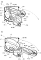
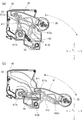
- FIG. 6 is an explanatory view showing the reciprocating motion of the arm 42 by the link mechanism 40.
- 6A shows a state where the arm 42 has moved to the limit in the storage direction B
- FIG. 6B shows a state where the arm 42 has moved to the limit in the extending direction A.
- the link mechanism 40 includes two link members 41 (a drive link 411 and a driven link 412), and is reciprocated in the extending direction A and the storage direction B supported by the link members 41. And an arm 42.
- the drive link 411 is formed with a circular through hole 411a penetrating in the width direction X at the tip.
- the support shaft 421a of the arm 42 By inserting the support shaft 421a of the arm 42 into the through hole 411a, the distal end portion of the drive link 411 and the arm 42 are rotatably connected to each other. Further, as described above, the base end portion of the drive link 411 can rotate to the case 50 by inserting the support shaft 522 of the second case half 52 into the through hole 411b formed in the base end portion. It is supported by.
- the gear portion 411 c formed at the base end portion of the drive link 411 meshes with the fifth reduction gear 35 of the reduction gear train 30.
- the driven link 412 is arranged on the extending direction A side with respect to the drive link 411.
- a circular through hole 412a penetrating in the width direction X is formed at the distal end of the driven link 412, and the support shaft 421b of the arm 42 is inserted into the through hole 412a, whereby the distal end of the driven link 412 is formed.
- the arm 42 are rotatably connected to each other.
- the base end portion of the driven link 412 is attached to the case 50 by fitting the shaft body 412b to the bearings 513 and 523 of the first case half 51 and the second case half 52. It is rotatably supported.
- the drive link 411 when the first motor 20 is rotated in the CW direction, the drive link 411 is also rotated in the CW direction, and the arm 42 is moved in the extending direction A.
- the arm 42 is also CCW. The arm 42 moves in the storage direction B.
- the load of the wind direction plate 91 and the arm 42 can be distributed to each link member 41 (the drive link 411 and the driven link 412). As a result, it is possible to prevent the stress supporting the load from being concentrated on only a part, and the entire apparatus is downsized. Further, since the sliding portion of the link mechanism 40 is almost only the joint portion, the sliding resistance accompanying the reciprocating motion of the arm 42 is relatively small.
- a stepping motor is used as the first motor 20 of the present embodiment.
- the stepping motor can rotate in both forward and reverse directions, and the rotation angle can be calculated from the number of steps. Therefore, it is not necessary to separately perform feedback control using a rotary encoder or the like in order to detect the arrangement angle of the drive link 411 at that time. Thereby, reduction of the number of parts in the whole apparatus and size reduction of the apparatus are achieved.
- the first drive source of the present invention is not necessarily a stepping motor, and other motors can be used as long as the motor can rotate in both forward and reverse directions. However, in that case, as described above, a position detecting means such as feedback control may be required separately.
- ribs 511 that support the link member 41 from the width direction X (the axial direction of the indirect portion of each link member) on the surface of the first case half 51 and the intermediate plate 53 on the link mechanism 40 side.
- ribs 531 are formed.
- the rib 511 and the rib 531 are linearly extending ribs protruding toward the link mechanism 40 along the rotation trajectory of each link member 41, and each link member 41 is slidably in contact with the rib 511 and the rib 531. Yes.
- each link member 41 Supporting each link member 41 with a linear rib prevents rattling in the width direction X of the link mechanism 40 and reduces sliding resistance with each link member 41.
- the louver device 10 is provided with a swing restricting portion that is a pair of locking portions that restrict the swingable range of the link mechanism 40 by abutting each other when the link mechanism 40 swings to a predetermined position. Yes.
- a swing restricting portion that is a pair of locking portions that restrict the swingable range of the link mechanism 40 by abutting each other when the link mechanism 40 swings to a predetermined position.
- two types of swing restricting portions are provided.
- FIG. 7 is an explanatory view showing the structure of the first swing restricting portion 60.
- 7A shows a state where the arm 42 has moved to the limit in the storage direction B
- FIG. 7B shows a state where the arm 42 has moved to the limit in the extending direction A.
- the 1st case half 51 of FIG. 7 is transparently displayed by the broken line.
- the first swing restricting portion 60 includes a protruding portion 61 formed on the drive link 411 and a contact portion 62 formed on the first case half 51.
- the protrusion 61 is a substantially rectangular tube-like engagement piece that protrudes from the drive link 411 along the width direction X (the axial direction of the indirect portion of the drive link) toward the first case half 51.
- the contact portion 62 is a rib-like engagement piece formed at a position where the link mechanism 40 abuts on the protrusion 61 when the link mechanism 40 swings to a predetermined position. The formation position of the contact portion 62 can be determined as appropriate according to the desired swing range of the link mechanism 40.
- the link mechanism 40 When the link mechanism 40 is swung to a predetermined position, the projection 61 formed on the drive link 411 and the contact portion 62 formed on the first case half 51 are brought into contact with each other, whereby the link The swingable range of the mechanism 40 can be limited to a desired range. Further, when the arm 42 is moved to the limit in the extending direction A side (that is, when the arm 42 is moved to a position where the projecting portion 61 and the contact portion 62 contact each other), the projecting portion 61 and the contact portion 62 are interposed. By supporting the drive link 411 on the first case half 51, the load on the arm 42 and the wind direction plate 91 can be further dispersed.
- the second swing restricting portion 65 is formed from opposed surfaces 66a and 67a of the bent portion 66 of the driven link 412 bent in a substantially L shape toward the inside of the link mechanism 40 and the arm side contact portion 67 of the arm 42. (See FIG. 6).
- the bent portion 66 is bent at an angle with which the facing surfaces 66a and 67a abut when the arm 42 extends to a predetermined position in the extending direction A.
- the bending angle of the bent portion 66 can be appropriately determined according to the desired extension range of the arm 42.
- FIG. 6 (b) shows the arm 42 moved in the extending direction A.
- the extension range of the arm 42 in FIG. 6B is limited by the first swing restricting portion 60, and the second swing restricting portion 65 is not acting.
- the movement of the arm 42 is limited by the contact of the facing surfaces 66a and 67a.
- the driven link 412 supports the arm 42 not only at its connecting portion but also at these facing surfaces 66a and 67a, so that the load of the arm 42 and the wind direction plate 91 can be further dispersed.
- the two types of swing restricting portions are provided, but only one of these swing restricting portions may be provided.
- FIG. 9 is an exploded perspective view showing the internal structure of the support unit 70.
- FIG. 10 is an explanatory view showing the reciprocating motion of the arm 72 by the support unit 70.
- the support unit 70 does not include a drive source, and is an auxiliary unit that supports the wind direction plate 91 following the operation of the louver devices 10, 10 ′.
- the support unit 70 has a case 71 composed of a first case half 711 and a second case half 712 that can be disassembled in the width direction X.
- An arm 72 and a follower link 73 are swingably supported on the case 71.
- the configuration and support structure of the driven link 73 are the same as the driven link 412 of the louver device 10.
- the arm 72 is not provided with a driving source corresponding to the second motor 25 of the louver device 10, and the wind direction plate 91 is rotated by the wind direction plate connecting portion 721 provided at the end portion in the extending direction A side. They are only combined as possible.
- a pin 751 that protrudes along the width direction X toward the second case half 712 is formed at the base end of the arm 72.
- the pin 751 is a cam follower that slides along a curved cam groove 752 provided in the second case half 712.
- the curved shape of the cam groove 752 is the same as the swing locus of the link mechanism 40 of the louver device 10.
- the width of the support unit 70 in the width direction X is smaller than that of the louver devices 10 and 10 ', and the air path of the air conditioner is not blocked.
- the use of the support unit 70 prevents the wind direction plate 91 from being bent by its own weight or wind pressure.
- louver device 11 According to another embodiment of the present invention will be described with reference to the drawings.
- components having the same or the same functions as those of the previous embodiment are denoted by the same reference numerals as those of the previous embodiment, and detailed description thereof is omitted.
- FIG. 11 is an explanatory view showing the reciprocating motion of the arm 42 in the louver device 11.
- 11A shows a state where the arm 42 has moved to the limit in the storage direction B
- FIG. 11B shows a state where the arm 42 has moved to the limit in the extending direction A.
- the louver device 11 is provided with a braking mechanism that brakes the arm 42 by a braking spring 95 that is a coil spring.
- the brake spring 95 in this embodiment is connected to the drive link 411 and the driven link 412, and when the arm 42 moves in the extending direction A, the driven link 412 is urged toward the storage direction B by its elastic force. Thus, the movement of the arm 42 in the extending direction A is braked.
- the arm 42 When moving the arm 42 in the extending direction A, the arm 42 is urged toward the extending direction A by the load of the arm 42 and the wind direction plate 91. In particular, when the wind direction plate 91 is receiving a large amount of wind pressure, the urging force is further increased. This may impair the stability of the opening / closing operation of the wind direction plate 91, may damage the power transmission member of the first motor 20, and may cause the first motor 20 to step out.
- connection target of the brake spring 95 is not limited to the drive link 411 and the driven link 412, and the same effect can be obtained by connecting the case 50 and a part of the link mechanism 40.
- a four-bar linkage mechanism is employed in order to realize the reciprocating movement of the arm member by the link mechanism with a minimum number of parts. More complex operations may be possible.
- first motor first drive source
- second motor second drive source (motor)
- 25a outer peripheral surface motor outer surface
- 251 upper surface 251a bearing portion
- 252 support Shaft 27 spacer member, 271 flat plate portion, 272 side plate portion, 271a bearing fixing hole, 271b support shaft fixing hole, 273 non-rotating sleeve
- 40 link mechanism 41 link member, 411 drive link, 412 driven link, 42 arm (arm Member, intermediate link), 42a arm case (case body), 421 first arm half (first case member), 422 second arm half (second case member), 422c stopper portion, 424 detent pin, 426 Hook part (lock piece), 427 lock hole, 43 motor room, 43a inner peripheral surface (first The inner surface of the over scan member), 50 cases (fixing portion), 91 louver, A extending direction, B housing direction
Landscapes
- Engineering & Computer Science (AREA)
- General Engineering & Computer Science (AREA)
- Mechanical Engineering (AREA)
- Power Engineering (AREA)
- Chemical & Material Sciences (AREA)
- Combustion & Propulsion (AREA)
- Air-Flow Control Members (AREA)
- Connection Of Plates (AREA)
- Housings, Intake/Discharge, And Installation Of Fluid Heaters (AREA)
- Air-Conditioning Room Units, And Self-Contained Units In General (AREA)
- Air Filters, Heat-Exchange Apparatuses, And Housings Of Air-Conditioning Units (AREA)
- Connection Of Motors, Electrical Generators, Mechanical Devices, And The Like (AREA)
Abstract
ケース部材の係止部が外部から視認不能に設けられることで意匠性が高められたケース体、および、風向板およびアームの荷重を分散して支持することが可能なルーバー装置を提供する。具体的には、第1ケース部材(421)および第2ケース部材(422)を備え、第1ケース部材の内面(43a)には、突起部であるロック片(426)が形成されており、第2ケース部材には、ロック片に係合する貫通孔であるロック穴(427)が形成されており、第1ケース部材の第2ケース部材への嵌合方向におけるロック片の厚みは、その基端側よりも先端側が薄くなるように形成されており、ロック片の基端から先端までの長さは、第1ケース部材および第2ケース部材が嵌め合わされたときに、ロック穴を貫通する長さであることを特徴とするケース体(42a)、およびこれを備えたルーバー装置(10)により解決する。
Description
本発明は、ケース体およびこれを備えたルーバー装置に関する。
下記特許文献1には、ケース(第2ケース312,322)に設けられた円弧状のカム面(ガイド面322e)に沿って、風向板(ルーバ5)を支持するアーム(第1ルーバ支持部材21、第2ルーバ支持部材22)のカムフォロア部(円弧部213,223)を摺動させることにより、アームを後退位置と前進位置との間で往復移動させるルーバー装置(ルーバ装置1)が開示されている。
上記特許文献1のルーバー装置は、風向板を支持するアームを前進位置に移動させ、風向板をエアコン本体から遠ざけて回動させる。そのため、上記特許文献1のルーバー装置は、アームがユーザーの目に触れやすく、アームに高い意匠性が要求される。特に、アーム内にモータ等の駆動源を配置すべく、複数のケース部材を嵌合することでアームを形成する場合、これらケース部材の係止部がユーザーから視認可能な位置に設けられていると、この露出した係止部がアームの意匠性を損ねるという課題がある。
また、上記特許文献1のルーバー装置では、アームを前進位置に移動させたときに、アームおよび風向板の荷重をアームの基端部およびケース(第1固定体31、第2固定体32)の開口近傍部のみで支える必要がある。特にアームのうちの一本(第1ルーバ支持部材21)には、風向板を回動させるためのモータ(第2モータ81)がその先端部に配置されており、さらに、風向板が受ける風圧もかかる荷重を大きくする。荷重を支持する応力が集中する部分の破損や変形を防止するため、特許文献1のアームおよびケースには相応の剛性をもたせる必要があり、部材の小型化が難しいという課題がある。
上記問題に鑑み、本発明が解決しようとする課題は、ケース部材の係止部が外部から視認不能に設けられることで意匠性が高められたケース体、および、このケース体を備え、風向板およびアームの荷重を分散して支持することが可能なルーバー装置を提供することにある。
上記課題を解決するため、本発明のケース体は、互いに嵌合される第1ケース部材および第2ケース部材を備え、前記第1ケース部材の内面には、該内面を基端としてその先端が該第1ケース部材の内側に突き出した突起部であるロック片が形成されており、前記第2ケース部材には、前記ロック片に係合する貫通孔であるロック穴が形成されており、前記第1ケース部材の前記第2ケース部材への嵌合方向における前記ロック片の厚みは、その基端側よりも先端側が薄くなるように形成されており、前記ロック片の基端から先端までの長さは、前記第1ケース部材および前記第2ケース部材が嵌め合わされたときに、前記ロック穴を貫通する長さであることを特徴とする。
第1ケース部材および第2ケース部材を係止するロック片およびロック穴が、ケース体の内側に配置される構成とすることにより、これらを外部から隠蔽することができ、ケース体の意匠性を高めることができる。
通常、ロック片とロック穴を用いた係止構造では、ロック片はロック穴を突き抜けない程度のサイズに設定される。ロック片がロック穴を貫通してしまうと、ロック片の先端がケース内の収容物などを損傷させるおそれがあるからである。本発明のロック穴は、ロック片よりもケース体の内側に配置されることから、例えばケース内の収容物がロック穴の近傍まで迫っている場合、ロック穴のケース内側への変位が制限される。この状況下で通常の高さのフックを用いると、ロック片の先端がロック穴の縁に乗り上げ、ケース体をいくら嵌め合わせてもケース体がロックされないという不具合が生じることがある。一方、ロック片がロック穴に入り込みやすくなるよう、ロック穴の位置をロック片に近づけるよう設計を変更したり、ロック片の位置をロック穴に近づけるよう設計を変更したりすると、係止後のケース体が十分に固定されず、ケース体にガタツキが生じることとなる。
本発明のロック片は、あえてロック穴を貫通する長さ(高さ)に設定されていることから、ケース体を嵌合する際の第1ケース部材の変形量が大きくなり、ロック片がロック穴に強力に押しつけられることとなる。さらに、本発明のロック片はその基端よりも先端の厚みが薄くなるよう形状されているから、ロック片の先端は湾曲しやすくなっている。これにより、本発明のケース体は、ロック穴のケース内側への変位が制限されている場合でも、ロック片がロック穴に入り込みやすく、ケース体がロックされないという不具合を回避することが可能とされている。
また、前記ロック片の基端から先端までの長さを該ロック片の高さとしたときに、前記第1ケース部材は、前記ロック片の高さ方向に、該ロック片の高さ程度の弾性変形が可能な可撓性材料からなることが好ましい。また、前記第1ケース部材は樹脂材料からなることが好ましい。
前記第1ケース部材に樹脂材料などの可撓性材料が用いられることにより、第1ケース部材の変形を利用した嵌合が可能となる。
また、前記ケース体のケース内にモータとともに収容され、該ケース内における該モータの位置を固定するスペーサー部材をさらに備え、前記モータの軸方向に沿う方向を前記ケース内における上下方向としたときに、前記スペーサー部材は、前記モータの出力軸側の端面を押さえることで前記ケース内における該モータの上下方向の位置を固定し、前記モータは、前記端面から前記出力軸の外周面に沿って円筒状に延びる軸受部を有するモータであり、前記スペーサー部材には、前記モータの前記軸受部が圧入される貫通孔である軸受固定穴が形成されており、前記ケース内における前記モータの外周面の周囲には、隙間が設けられることが好ましい。
通常、モータは、モータケース内の空間の成形精度は高いものの、個体ごとのモータケースの肉厚のバラつきなど、モータケースの外面には内面よりも大きな誤差が現れることが見込まれる。そのため、ケース体の内部におけるモータの位置決めを例えばモータケースの外周面を支持することで行うような場合には、モータがケース体に収まらなかったり、逆にモータにガタツキが生じたりすることがある。本構成のケース体は、ケース内におけるモータの位置決めを行うスペーサー部材を別途備え、スペーサー部材を用いてケース内におけるモータの上下方向の位置を固定し、さらにモータケースの外周面に比べて誤差の影響が小さい軸受部でモータを支持することにより、モータケースの外面に現れる誤差を吸収することが可能とされている。
また、前記スペーサー部材は、前記ケース内におけるその周方向角度および径方向位置が固定されており、前記モータは、前記端面から垂直に延びる棒状体である支軸を有するモータであり、前記スペーサー部材には、前記モータの前記支軸が圧入される貫通孔である支軸固定穴が形成されており、前記モータは、該モータの前記軸受部が前記スペーサー部材の前記軸受固定穴に、該モータの前記支軸が前記スペーサー部材の前記支軸固定穴にそれぞれ圧入されることにより、前記ケース内におけるその周方向角度および径方向位置が固定されることが好ましい。
ケース内に固定されたスペーサー部材でモータの軸受部および支軸の二点を支持することにより、ケース内におけるモータの上下方向位置およびその出力軸の位置のみならず、モータの周方向角度も固定することができる。これにより、モータケースの外面に現れる誤差を吸収しつつ、ケース内におけるモータの絶対位置を固定することが可能となり、モータのガタツキに伴う騒音や部品寿命の低下を抑えることができる。
上記課題を解決するため、本発明のルーバー装置は、第1駆動源と、前記第1駆動源の駆動力により揺動するリンク機構と、前記リンク機構を収容可能な固定部と、を備え、前記リンク機構は、請求項1から請求項5のいずれか一項の記載のケース体を有するアーム部材と、該アーム部材を支持し、該アーム部材を延出方向および収納方向へ往復移動させる複数のリンク部材を有しており、前記複数のリンク部材は、前記第1駆動源により駆動される駆動リンクと、該駆動リンクの動作に前記アーム部材を介して追従する従動リンクと、を有しており、前記駆動リンクは、その先端側が前記アーム部材に、基端側が前記第1駆動源に直接または他の部材を介して連結されており、前記従動リンクは、その先端側が前記アーム部材に、基端側が前記固定部に連結されており、前記アーム部材の前記延出方向側端部には、板状部材である風向板が回動可能に連結されていることを特徴とする。
風向板を開閉するアーム部材をリンク機構で往復移動させることにより、風向板とアーム部材の荷重を各リンク部材に分散させることができる。これにより荷重を支持する応力が一部のみに集中することを防ぐことができ、装置全体の小型化を図ることが可能になる
また、前記リンク機構は前記アーム部材を中間リンクとする四節リンク機構であり、前記従動リンクは前記駆動リンクよりも前記延出方向側に配置されていることが好ましい。
リンク機構を四節リンクとすることにより、リンク機構によるアーム部材の往復移動を最小の部品点数で実現することができる。また、従動リンクは第1駆動源に連結される必要がないことから、駆動リンクに比べてその配置場所に関する制約が少ない。そのため、従動リンクを駆動リンクよりもアーム部材の延出方向側に配置することにより、従動リンクを装置の延出方向側の端部に配置することができ、アーム部材をより遠くまで支持することが可能となる。
また、前記アーム部材の前記延出方向の側端部には、第2駆動源が配置され、前記風向板は前記第2駆動源の駆動力により所定の角度範囲内において回動可能であることが好ましい。
アーム部材の延出方向の側端部に設けた第2駆動源により風向板を回動させることで、風向板のより複雑な動作が可能となり、風向制御の自由度を高めることができる。
また、前記第2駆動源はステッピングモータであることが好ましい。
ステッピングモータは正逆両方向に回転可能であり、また、ステップ数によりその回転角度を算出することができる。よって、風向板のその時々における配置角度を検出するために別途ロータリエンコーダなどによるフィードバック制御を行う必要がない。これにより、装置全体における部品点数の削減および装置の小型化を図ることができる。
本発明のケース体およびこれを備えたルーバー装置によれば、ケース体の意匠性を高めることができ、また、風向板およびアームの荷重を分散して支持することが可能となる。
以下、本発明にかかるルーバー装置の実施形態について図面を用いて説明する。本実施形態にかかるルーバー装置は、図示しない空調機の送風口に設置され、その風向を制御する装置である。尚、以下の説明において「幅方向」とは、図1の座標軸表示に示されるX方向を、「前後方向」とは同座標軸表示に示されるY方向を、「上下方向」とは同座標軸表に示されるZ方向をいう。
(全体構成)
図1はルーバー装置の配置構成の一例を示す外観斜視図である。図1の配置例では、一枚の共通の風向板91を、二台のルーバー装置10,10´および一台のサポートユニット70(以下、これらを総称して「ルーバー装置10等」ともいう。)で支持している。二台のルーバー装置10,10´は同一の装置であり、以下に説明するルーバー装置10の構成はルーバー装置10´の構成でもある。これらルーバー装置10等はいずれも、風向板91よりも後方(図示しない空調機の筐体側)に配置されている。ルーバー装置10,10´は風向板91の長手方向における両端近傍に配置され、サポートユニット70は同長手方向における略中央に配置されている。
図1はルーバー装置の配置構成の一例を示す外観斜視図である。図1の配置例では、一枚の共通の風向板91を、二台のルーバー装置10,10´および一台のサポートユニット70(以下、これらを総称して「ルーバー装置10等」ともいう。)で支持している。二台のルーバー装置10,10´は同一の装置であり、以下に説明するルーバー装置10の構成はルーバー装置10´の構成でもある。これらルーバー装置10等はいずれも、風向板91よりも後方(図示しない空調機の筐体側)に配置されている。ルーバー装置10,10´は風向板91の長手方向における両端近傍に配置され、サポートユニット70は同長手方向における略中央に配置されている。
風向板91のルーバー装置10等との対向面には、ルーバー装置10等との連結部であるアーム接続片911,912が形成されている。風向板91は、ルーバー装置10等のアーム42,72に設けられた風向板接続部262,721にアーム接続片911,912が結合されることにより、これらアーム42,72に支持されるとともに、これらアーム42,72と一体的に動作する。
ルーバー装置10,10´は、ルーバー装置10,10´が備える駆動源の駆動力により風向板91を開閉および回動させる駆動装置である。一方、サポートユニット70はこれらルーバー装置10,10´の動作に追従して風向板91を支持する補助的なユニットである。風向板91の長手方向における長さが短い場合や、ルーバー装置10,10´で風向板91の両端のみを支持した場合でも、風向板91が自重によりたわみが生じない程度の剛性を備えている場合には、サポートユニット70は省略しても良い。
(ルーバー装置の内部構造)
図2はルーバー装置10(およびルーバー装置10´)の内部構造を示す分解斜視図である。ルーバー装置10は、ステッピングモータである第1モータ20(第1駆動源)と、第1モータ20の駆動力により揺動するリンク機構40と、第1モータ20の回転を減速してリンク機構40に伝達する減速歯車列30と、リンク機構40および減速歯車列30を収容するケース50(固定部)と、を備えている。
図2はルーバー装置10(およびルーバー装置10´)の内部構造を示す分解斜視図である。ルーバー装置10は、ステッピングモータである第1モータ20(第1駆動源)と、第1モータ20の駆動力により揺動するリンク機構40と、第1モータ20の回転を減速してリンク機構40に伝達する減速歯車列30と、リンク機構40および減速歯車列30を収容するケース50(固定部)と、を備えている。
リンク機構40は、二つのリンク部材41と、これらリンク部材41に支持されて後述する延出方向Aおよび収納方向B(図6参照)へ往復移動するアーム42(アーム部材)と、を有している。リンク部材41は、第1モータ20により駆動される駆動リンク411と、駆動リンク411の動作にアーム42を介して追従する従動リンク412と、を有している。リンク機構40は、駆動リンク411および従動リンク412のほか、ケース50を固定リンクとし、アーム42を中間リンクとする四節リンク機構を構成している。
ケース50は、幅方向Xに分解可能な第1ケース半体51、第2ケース半体52、および中板53により構成される。これら第1ケース半体51、第2ケース半体52、および中板53は止めねじ59で結合されることにより一体化される。リンク機構40は、第1ケース半体51および中板53により区画される空間に配置され、減速歯車列30は、第2ケース半体52および中板53により区画される空間に配置される。
第1モータ20は第2ケース半体52の底面(幅方向Xに直交する面)の外側に配置され、止めねじ29により第2ケース半体52に固定される。第2ケース半体52の底面における、第1モータ20のピニオンギヤ21の位置に対応する部位には、第2ケース半体52の開口側(ケース50の内部側)に向かって突出した有蓋筒状のピニオンカバー部521が設けられている。ピニオンカバー部521はピニオンギヤ21側が開口しており、ピニオンギヤ21はピニオンカバー部521の内側に収容される。ピニオンカバー部521には、その周方向の一部が切り欠かれた開口部である窓部521aが設けられており、ピニオンカバー部521内に収容されたピニオンギヤ21は、その一部の歯部が窓部521aから第2ケース半体52の内側に露出している。
減速歯車列30は、それぞれ大径歯車部および小径歯車部を備える複合歯車の輪列である。減速歯車列30の各歯車部材はそれぞれ、第2ケース半体52と中板53との間に立設された支軸36に回転可能に支持されている。減速歯車列30は、第1モータ20のピニオンギヤ21の回転を、大径歯車部から小径歯車部へと順次伝達することにより、ピニオンギヤ21の回転を減速して駆動リンク411の歯車部411cに伝達する。第1モータ20の回転を減速して駆動リンク411に伝達することにより、一般的な出力のモータを用いてアーム42を往復移動させることが可能とされている。
リンク機構40を構成する駆動リンク411の基端部(基端側)には、幅方向Xに貫通された貫通孔411bが形成されており、第2ケース半体52に立設された支軸522が貫通孔411bに挿通されることで、駆動リンク411の基端部はケース50に回転可能に支持される。
また、駆動リンク411の基端部には、減速歯車列30側に向かって延びる歯車部411cが設けられている。中板53における歯車部411cの位置に対応する部位には、歯車部411cが挿通される切欠部533が形成されている。歯車部411cは、切欠部533に挿通されることにより、中板53を貫通して減速歯車列30の最終歯車と噛合する。歯車部411cが減速歯車列30の最終歯車と噛合することにより、第1モータ20の駆動力は減速歯車列30および歯車部411cを介して駆動リンク411へと伝達される。
リンク機構40の従動リンク412は、その基端部(基端側)に、軸線が幅方向Xと平行な略円筒形状の軸体412bが設けられている。第1ケース半体51および第2ケース半体52における軸体412bの位置に対応する部位には、幅方向Xに貫通された円形の貫通孔である軸受513,523が形成されている。従動リンク412は、軸体412bが軸受513,523に嵌合されることによりケース50に回転可能に支持される。
尚、本発明でいうリンク部材41(駆動リンク411、従動リンク412)の「基端」とは、固定関節、つまり所定位置に固定され、回転は許容されるが上下方向Zおよび前後方向Yへの揺動が規制された端部をいい、「先端」とは、自由関節、つまり回転および揺動が許容された端部をいう。
また、本実施形態においては、駆動リンク411および従動リンク412の基端部がいずれもケース50に支持されているが、これら基端部は必ずしもケース50に支持される必要はない。例えば、図示しない空調機の筐体など、位置が固定された部材(固定部)であって、上記基端部を回転可能に支持することができ、かつアーム42および風向板91の荷重により変形しない程度の剛性を備える部材であれば、ケース50に代替可能である。
(アームの内部構造)
図3はアーム42の内部構造を示す分解斜視図である。アーム42は、アーム42のケース体であるアームケース42aを備えている。アームケース42aは、幅方向Xに嵌合された第1ケース部材である第1アーム半体421、および第2ケース部材である第2アーム半体422により構成されている。第1アーム半体421および第2アーム半体422の延出方向A側の端部には、嵌合された該端部を係止するフック部426およびロック穴427がそれぞれ設けられており、第1アーム半体421および第2アーム半体422は、これらフック部426およびロック穴427と3本の止めねじ429により固定される。
図3はアーム42の内部構造を示す分解斜視図である。アーム42は、アーム42のケース体であるアームケース42aを備えている。アームケース42aは、幅方向Xに嵌合された第1ケース部材である第1アーム半体421、および第2ケース部材である第2アーム半体422により構成されている。第1アーム半体421および第2アーム半体422の延出方向A側の端部には、嵌合された該端部を係止するフック部426およびロック穴427がそれぞれ設けられており、第1アーム半体421および第2アーム半体422は、これらフック部426およびロック穴427と3本の止めねじ429により固定される。
アームケース42aの延出方向A側の端部およびその近傍部には、第2駆動源である第2モータ25が収容されるモータ室43が設けられている。第2モータ25は風向板91を所定の角度範囲内において回動させるステッピングモータである。第2モータ25のDカットが施された出力軸253にはピニオンギヤ261が装着されている。また、第2モータ25に移動不能に固定され、出力軸253の軸方向と平行に延びる棒状体である支軸252(後述)には、風向板接続部262が回転可能に支持されている。ピニオンギヤ261の回転は風向板接続部262の歯車部262aを介して減速され、風向板接続部262へと伝達される。本実施形態においては、第2モータ25に固定された支軸252により風向板接続部262が支持されていることで、出力軸253に対する風向板接続部262の相対的な位置関係が一定に保たれている。これにより、ピニオンギヤ261と風向板接続部262の歯車部262aの噛合い精度が高められ、これら歯車部材のガタツキによる騒音や部品寿命の低下が抑えられている。
第2アーム半体422のモータ室43を構成する部位には、幅方向Xに貫通された円形の開口部422aが形成されており、風向板接続部262は開口部422aからアームケース42aの外部に露出している。これにより、アーム42の風向板接続部262と風向板91のアーム接続片911とが結合可能となる。風向板91を第2モータ25により回動させる構成とすることにより、風向板91のより複雑な動作が可能となり、風向制御の自由度が高められている。
アームケース42aにおける、モータ室43よりも収納方向B側の部分には、波形に形成されたリブ423がその内部に設けられており、リブ423によりアームケース42aの剛性が高められている。尚、リブ423の一部は、後述する第2揺動規制部65のアーム側当接部67としての用途を兼ねている。
図8は第2モータ25のリード線93の取り回し構造を説明する図である。第2モータ25のコネクタ259に接続されたリード線93は、アーム42の内部におけるリブ423の上側に設けられた隙間を通ってケース50内へと引き込まれる。ケース50内に引き込まれたリード線93は、駆動リンク411の上側を通って中板53の後方(図8視左側)に形成されたガイド片532に引き込まれ、そしてガイド片532に案内されて引出口54からルーバー装置10の外部へと引き出される。尚、図8(b)に示すように、引出口54は第1ケース半体51および第2ケース半体52により区画される開口である。
(スペーサー部材の構成)
アームケース42aのモータ室43には、第2モータ25とともに、モータ室43内における第2モータ25の位置を固定するスペーサー部材27が収容されている。スペーサー部材27は、略円板形状の平板部271と、平板部271の周縁から第2モータ25側に延びる一対の側板部272とにより構成されている。一対の側板部272は、平板部271の周縁において線対称となる位置および範囲に形成されている。
アームケース42aのモータ室43には、第2モータ25とともに、モータ室43内における第2モータ25の位置を固定するスペーサー部材27が収容されている。スペーサー部材27は、略円板形状の平板部271と、平板部271の周縁から第2モータ25側に延びる一対の側板部272とにより構成されている。一対の側板部272は、平板部271の周縁において線対称となる位置および範囲に形成されている。
第2モータ25の軸方向に沿う方向(本実施形態においては幅方向Xに平行する方向)をモータ室43の内部における上下方向(第1アーム半体421側を「下」、第2アーム半体422側を「上」とする。以下、モータ室43内部の説明において「上」および「下」とは同上下方向をいうものとする。)としたときに、スペーサー部材27の平板部271は、第2モータ25の出力軸253側の端面である上面251に被せられ、上面251を下方に押さえることで、モータ室43内における第2モータ25の上下方向の位置を固定する。一対の側板部272は、第2アーム半体422の内周面および第2モータ25の外周面25aとは接触しておらず、これらの間にはそれぞれ隙間が設けられている。また、第2モータ25の外周面25aとモータ室43の内周面43aも接触はしておらず、これらの間には隙間が設けられている。
スペーサー部材27の平板部271における第2アーム半体422側の面には、第2アーム半体422側に延びる略円筒状の回り止めスリーブ273が二つ形成されている。各回り止めスリーブ273は、その周方向の一部にスリットが設けられており、これにより径方向外側への弾性変形が可能となっている。第2アーム半体422のモータ室43内面には、各回り止めスリーブ273の形成位置に対応する位置に、各回り止めスリーブ273に嵌合される突起部である回り止めピン424が形成されている。これら回り止めピン424と回り止めスリーブ273とが嵌合されることにより、スペーサー部材27は、モータ室43内におけるその周方向角度および径方向位置(上下方向に直交する方向における位置。以下の説明においても同じ。)が固定される。
第2モータ25の上面251には、上面251から出力軸253の外周面に沿って円筒状に延びる軸受部251aが形成されており、平板部271における軸受部251aの形成位置に対応する位置には、軸受部251aが圧入される貫通孔である軸受固定穴271aが形成されている。さらに、第2モータ25の上面251には、上面251から垂直に延びる棒状体である支軸252が移動不能に固定されており、平板部271における支軸252の形成位置に対応する位置には、支軸252が圧入される貫通孔である支軸固定穴271bが形成されている。上で述べたように、スペーサー部材27はモータ室43内におけるその位置や角度が固定されている。第2モータ25は、その軸受部251aがスペーサー部材27の軸受固定穴271aに、その支軸252がスペーサー部材27の支軸固定穴271bにそれぞれ圧入されることにより、スペーサー部材27に対する相対的な周方向角度およびモータ室43内における径方向位置が固定される。つまり、モータ室43内における第2モータ25の絶対位置が固定される。
通常、モータは、モータケース内の空間の成形精度は高いものの、個体ごとのモータケースの肉厚のバラつきなど、モータケースの外面には内面よりも大きな誤差が生じことが見込まれる。そのため、ケース体の内部におけるモータの位置決めを例えばモータケースの外周面を支持することにより行うような場合には、モータがケース体に収まらなかったり、逆にモータにガタツキが生じたりすることがある。本実施形態のモータ室43は、第2モータ25の外周面25aの周囲に隙間を設けつつ、モータ室43内に別途備えたスペーサー部材27を第2モータ25の上面251に被せ、成形誤差の影響が小さい軸受部251aと支軸252を利用して、モータ室43内における第2モータ25の絶対位置を固定することにより、第2モータ25の外面に現れる誤差を吸収しつつ、第2モータ25のガタツキに伴う騒音や部品寿命の低下を抑えることが可能とされている。
(アームケースの係止構造)
図12は、フック部426およびロック穴427を用いたアームケース42aの係止構造の説明図である。図12(a)はアーム42を第2アーム半体422側から見た平面図、図12(b)は図12(a)のC-C方向断面図、図12(c)は図12(b)の破線Dで囲んだ部分の拡大図である。
図12は、フック部426およびロック穴427を用いたアームケース42aの係止構造の説明図である。図12(a)はアーム42を第2アーム半体422側から見た平面図、図12(b)は図12(a)のC-C方向断面図、図12(c)は図12(b)の破線Dで囲んだ部分の拡大図である。
図12(c)に示すように、フック部426は、第1アーム半体421のモータ室43の内周面43aを基端としてその先端がモータ室43の内側に突き出した突起部である。第2アーム半体422は、フック部426の形成位置に対応する位置に舌片状のストッパ部422cを有しており、ストッパ部422cには、フック部426に係合する貫通孔であるロック穴427が形成されている。フック部426およびロック穴427は、アームケース42aの延出方向A側の端部を係止する一対のロック片およびロック穴である。これらフック部426およびロック穴427がアームケース42aの内側に配置されていることにより、これらが外部から隠蔽され、アームケース42aの意匠性が高められている。
これら第1アーム半体421および第2アーム半体422の嵌合方向(本実施形態においては幅方向X)におけるフック部426の厚みは、その基端側よりも先端側が薄くなるように形成されている。より具体的には、フック部426は、図12(c)においてフック部426の上面に相当する面が、その基端から先端に向かって漸次低くなるテーパ面426aとして形成されている。
また、ストッパ部422cの先端部には、第1アーム半体421および第2アーム半体422が嵌合される際に、フック部426のテーパ面426aが乗り上げるテーパ面が形成されている。フック部426の基端から先端までの長さをフック部426の高さとしたときに、第1アーム半体421は、フック部426の高さ方向に、フック部426の高さ程度の弾性変形が可能な樹脂材料により形成されている。
本実施形態におけるフック部426の高さは、ロック穴427を貫通する高さとされている。通常、ロック片とロック穴を用いた係止構造では、ロック片はロック穴を突き抜けない程度のサイズに設定される。ロック片がロック穴を貫通してしまうと、ロック片の先端がケース内の収容物などを損傷させるおそれがあるからである。本実施形態のロック穴427は、フック部426よりもモータ室43の内側に配置されている。また、モータ25の外周面25aはロック穴427が形成されたストッパ部422cの近傍まで迫っており、ロック穴427のモータ室43内側への変位は制限されている。この状況下で通常の高さのロック片を用いた場合、ロック片の先端がロック穴の縁に乗り上げ、ケース体をいくら嵌め合わせてもケース体がロックされないという不具合が生じることがある。本実施形態のフック部426は、あえてロック穴427を貫通する高さに設定されていることから、アームケース42aを嵌合する際の第1アーム半体421の変形量が大きくなり、フック部426がロック穴427に強力に押しつけられることとなる。さらに、本実施形態のフック部426はその基端よりも先端の厚みが薄くなるよう形状されているから、フック部426の先端は湾曲しやすくなっている。これにより、本実施形態のアームケース42aでは、ロック穴427(ストッパ部422c)のモータ室43内側への変位が制限されていながらも、フック部426がロック穴427に押し込まれやすくなっており、アームケース42aがロックされないという不具合を回避することが可能とされている。
(減速歯車列)
図4は減速歯車列30の噛合構造を示す透過図である。図4において点線で示した歯部は、各歯車部材の図視背面側の歯車部を表したものである。
図4は減速歯車列30の噛合構造を示す透過図である。図4において点線で示した歯部は、各歯車部材の図視背面側の歯車部を表したものである。
ピニオンカバー部521の窓部521aから露出したピニオンギヤ21の歯部は、減速歯車列30を構成する第1減速歯車31の大径歯車部と噛合している。以降、第1減速歯車31の小径歯車部は第2減速歯車32の大径歯車部に、第2減速歯車32の小径歯車部は第3減速歯車33の大径歯車部に、第3減速歯車33の小径歯車部は第4減速歯車34の大径歯車部に、第4減速歯車34の小径歯車部は第5減速歯車35の大径歯車部に順次噛合している。そして、第5減速歯車35の小径歯車部は駆動リンク411の歯車部411cと噛合している。これにより第1モータ20の回転は減速されて駆動リンク411へと伝達される。
(トルクリミッタ機構)
減速歯車列30の歯車部材のうち、第1減速歯車31は、所定の閾値を超えるトルクが印加されたときに、空転によりその超過トルクを消費することで伝達トルクを抑制する、トルクリミッタ機構(過負荷保護機構)を備えた歯車部材である。上記所定の閾値トルクとしては、ルーバー装置10の通常動作時において実際に第1減速歯車31に伝達されうるトルクの上限値に適宜余裕値を加算し、異常の蓋然性が高いと判断可能なトルクを設定すればよい。
減速歯車列30の歯車部材のうち、第1減速歯車31は、所定の閾値を超えるトルクが印加されたときに、空転によりその超過トルクを消費することで伝達トルクを抑制する、トルクリミッタ機構(過負荷保護機構)を備えた歯車部材である。上記所定の閾値トルクとしては、ルーバー装置10の通常動作時において実際に第1減速歯車31に伝達されうるトルクの上限値に適宜余裕値を加算し、異常の蓋然性が高いと判断可能なトルクを設定すればよい。
図5は第1減速歯車31の外観斜視図(図5(a))および、図5(a)に示される第1減速歯車31のA-A方向断面図(図5(b))である。以下、第1減速歯車31およびトルクリミッタ機構に関する説明において、「上」および「下」とは、図5(a)(b)における上下をいい、また「平面視」とは、第1減速歯車31の上方から第1減速歯車31を下方に見下ろす視線方向をいう。
第1減速歯車31は、別部材からなる上側の小径歯車部311と下側の大径歯車部312とにより構成されている。小径歯車部311および大径歯車部312は、共通の軸部314により支持され、互いに独立して回転可能である。小径歯車部311と大径歯車部312との間には、コイルばね313が上下方向に圧縮された状態で配置されており、コイルばね313により小径歯車部311は上方に、大径歯車部312は下方に付勢されている。
小径歯車部311は、コイルばね313がその下面に当接することにより上方へ付勢されるとともに、軸部314の上端近傍部から径方向外側に延出した鉤部314aにより上方への移動が係止されている。また、図5(a)に示すように、鉤部314aが配置される小径歯車部311上端の開口部311aは、平面視十字形に形成されている。これにより、鉤部314aおよび開口部311aは互いに周方向に係合し、小径歯車部311および軸部314は周方向に常に一体に回転することとなる。
大径歯車部312は、軸部314に圧入され、その上面および下面には円環形状の平板部材である金属板315が同軸状に配置されている。大径歯車部312は、コイルばね313が大径歯車部312の上面側に配置された金属板315に当接することにより、かかる金属板315を介して下方へと付勢される。また、大径歯車部312の下面側に配置された金属板315は、軸部314の下端近傍部に形成された拡径部314bの上面に載置されており、かかる金属板315および拡径部314bにより大径歯車部312の下方への移動が係止されている。そのため、大径歯車部312は、コイルばね313の付勢力により拡径部314bに押し付けられることとなる。その結果、大径歯車部312は、軸部314への圧入による摩擦抵抗、および、コイルばね313で拡径部314bに押し付けられることによる摩擦抵抗により、軸部314と周方向に連れ回って回転する。
第1減速歯車31は上記構成を備えることにより、軸部314と大径歯車部312とがその摩擦抵抗で連れ回り可能なトルクの範囲内では、小径歯車部311(および軸部314)と大径歯車部312は周方向に一体に回転し、上記摩擦抵抗を超えるトルクが加えられたときには、小径歯車部311(および軸部314)と大径歯車部312のいずれか一方が空転する。
減速歯車列30が、トルクリミッタ機構を備えた第1減速歯車31を有することにより、例えば第1モータ20のホールド中に、風向板91がユーザーにより手動で開閉され、減速歯車列30やリンク機構40など第1モータ20の動力伝達部材に予期しない外力が加えられたときでも、第1モータ20の脱調や動力伝達部材の破損を防止することが可能とされている。また、例えば第1モータ20のイニシャライズ動作において、第1モータ20の認識角度と駆動リンク411の実際の配置角度とを同期させるため、第1モータ20を駆動リンク411の初期位置方向へ意図的に数ステップ脱調させる場合でも、動力伝達部材の損傷や異常音を低減することが可能とされている。
また、図4に示すように、第1減速歯車31は第1モータ20のピニオンギヤ21に噛合している。本発明のトルクリミッタ機構は、当然、通常動作時の伝達トルクよりも大きなトルクが印加されたときに作動する。従って、通常動作時における伝達トルクが大きな歯車部材(例えば第5減速歯車35)にトルクリミッタ機構をもたせると、それ以上の外力(トルク)が加えられたときにしか保護効果は得られない。減速歯車列30のうち、伝達トルクが最も小さな第1減速歯車31にトルクリミッタ機構をもたせることにより、異常に対して機敏にトルクリミッタ機構を作動させることが可能とされている。
(アームの往復動作)
図6はリンク機構40によるアーム42の往復動作を示す説明図である。図6(a)はアーム42が収納方向Bに限界まで移動した状態、図6(b)はアーム42が延出方向Aに限界まで移動した状態を示している。
図6はリンク機構40によるアーム42の往復動作を示す説明図である。図6(a)はアーム42が収納方向Bに限界まで移動した状態、図6(b)はアーム42が延出方向Aに限界まで移動した状態を示している。
図2および図6に示すように、リンク機構40は、二つのリンク部材41(駆動リンク411および従動リンク412)と、これらリンク部材41に支持されて延出方向Aおよび収納方向Bへ往復移動するアーム42と、を有している。アーム42の延出方向A側の端部には、風向板91を回動させる駆動源である第2モータ25が配置されている。
駆動リンク411は、幅方向Xに貫通する円形の貫通孔411aがその先端部に形成されている。かかる貫通孔411aにアーム42の支軸421aが挿通されることで、駆動リンク411の先端部とアーム42とが互いに回転可能に連結されている。また、上でも述べたように、駆動リンク411の基端部は、基端部に形成された貫通孔411bに第2ケース半体52の支軸522が挿通されることでケース50に回転可能に支持されている。また、駆動リンク411の基端部に形成された歯車部411cは、減速歯車列30の第5減速歯車35と噛合している。
従動リンク412は、駆動リンク411よりも延出方向A側に配置されている。従動リンク412の先端部には、幅方向Xに貫通された円形の貫通孔412aが形成されており、貫通孔412aにアーム42の支軸421bが挿通されることで、従動リンク412の先端部とアーム42とが互いに回転可能に連結されている。また、上でも述べたように、従動リンク412の基端部は、軸体412bが第1ケース半体51および第2ケース半体52の軸受513,523に嵌合されることによりケース50に回転可能に支持されている。
本実施形態においては、第1モータ20がCW方向へ回転すると、駆動リンク411もCW方向へ回動し、アーム42は延出方向Aへと移動する、CCW方向へ回転すると、アーム42もCCW方向へ回動し、アーム42は収納方向Bへと移動する。
風向板91を開閉するアーム42をリンク機構40で往復移動させることにより、風向板91とアーム42の荷重を各リンク部材41(駆動リンク411および従動リンク412)に分散させることができる。これにより荷重を支持する応力が一部のみに集中することを防ぐことができ、装置全体の小型化が図られている。また、リンク機構40の摺動部はほぼその関節部のみであることから、アーム42の往復動作に伴う摺動抵抗は比較的小さなものとなる。
また、本実施形態の第1モータ20にはステッピングモータが用いられている。ステッピングモータは正逆両方向に回転可能であり、また、ステップ数によりその回転角度を算出することができる。よって、駆動リンク411のその時々における配置角度を検出するために別途ロータリエンコーダなどによるフィードバック制御を行う必要がない。これにより、装置全体における部品点数の削減および装置の小型化が図られている。この点は第2モータ25についても同様である。尚、本発明の第1駆動源は必ずしもステッピングモータである必要はなく、正逆両方向に回転可能なモータであれば他のモータを使用することもできる。但しその場合、上でも述べたように、別途フィードバック制御などの位置検出手段が必要になることがある。
また、第1ケース半体51と中板53におけるリンク機構40側の面には、リンク部材41を幅方向X(各リンク部材の間接部の軸方向)から支持するリブ511(図7参照)とリブ531(図6参照)が形成されている。リブ511およびリブ531は各リンク部材41の回動軌跡に沿ってリンク機構40側に突出した線状に延びるリブであり、各リンク部材41はリブ511およびリブ531に摺動可能に接触している。
線状のリブで各リンク部材41を支持することにより、リンク機構40の幅方向Xのガタつきが防止されるとともに、各リンク部材41との摺動抵抗が低減されている。
(揺動規制部)
ルーバー装置10には、リンク機構40が所定位置まで揺動したときに、互いに当接することでリンク機構40の揺動可能範囲を規制する一対の係止部である揺動規制部が設けられている。尚、本実施形態では第1揺動規制部60および第2揺動規制部65の二種類の揺動規制部が設けられている。
ルーバー装置10には、リンク機構40が所定位置まで揺動したときに、互いに当接することでリンク機構40の揺動可能範囲を規制する一対の係止部である揺動規制部が設けられている。尚、本実施形態では第1揺動規制部60および第2揺動規制部65の二種類の揺動規制部が設けられている。
図7は第1揺動規制部60の構造を示す説明図である。図7(a)はアーム42が収納方向Bに限界まで移動した状態、図7(b)はアーム42が延出方向Aに限界まで移動した状態を示している。尚、図7の第1ケース半体51は破線により透過表示されている。
第1揺動規制部60は、駆動リンク411に形成された突起部61と、第1ケース半体51に形成された当たり部62とからなる。突起部61は、駆動リンク411から幅方向X(駆動リンクの間接部の軸方向)に沿って第1ケース半体51側に突出した略角筒状の係合片である。当たり部62は、リンク機構40が所定位置まで揺動したときに突起部61と当接する位置に形成されたリブ状の係合片である。当たり部62の形成位置は、リンク機構40の所望の揺動範囲に応じて適宜定めることができる。
リンク機構40が所定位置まで揺動したときに、駆動リンク411に形成された突起部61と、第1ケース半体51に形成された当たり部62とを当接させる構成とすることにより、リンク機構40の揺動可能範囲を所望の範囲に制限することができる。また、アーム42を延出方向A側に限界まで移動させたとき(つまり突起部61と当たり部62とが当接する位置まで移動させたとき)には、突起部61と当たり部62とを介して駆動リンク411が第1ケース半体51に支えられることにより、アーム42と風向板91の荷重をさらに分散させることが可能となる。
第2揺動規制部65は、リンク機構40の内側に向かって略L字形状に屈曲した従動リンク412の屈曲部66と、アーム42のアーム側当接部67との対向面66a,67aからなる(図6参照)。屈曲部66は、アーム42が延出方向Aにおける所定位置まで延出したときに、これら対向面66a,67aが当接する角度に屈曲している。屈曲部66の屈曲角度は、アーム42の所望の延出範囲に応じて適宜定めることができる。
図6(b)には延出方向Aへ移動したアーム42が示されている。図6(b)のアーム42は第1揺動規制部60によりその延出範囲が制限されており、第2揺動規制部65は作用していない。しかし、アーム42にさらに大きな荷重がかかり、アーム42が下方にたわんだ場合には、これら対向面66a,67aが当接することによりアーム42の移動が制限される。このように、従動リンク412がアーム42をその連結部のみならずこれら対向面66a,67aでも支えることにより、アーム42と風向板91の荷重をさらに分散させることが可能とされている。
尚、本実施形態においては上記二種類の揺動規制部が設けられているが、これら揺動規制部はいずれか一方のみであっても良い。
(サポートユニット)
図9はサポートユニット70の内部構造を示す分解斜視図である。図10はサポートユニット70によるアーム72の往復動作を示す説明図である。サポートユニット70は駆動源を備えず、ルーバー装置10,10´の動作に追従して風向板91を支持する補助的なユニットである。
図9はサポートユニット70の内部構造を示す分解斜視図である。図10はサポートユニット70によるアーム72の往復動作を示す説明図である。サポートユニット70は駆動源を備えず、ルーバー装置10,10´の動作に追従して風向板91を支持する補助的なユニットである。
サポートユニット70は幅方向Xに分解可能な第1ケース半体711および第2ケース半体712からなるケース71を有している。ケース71にはアーム72および従動リンク73が揺動可能に支持されている。
従動リンク73の構成および支持構造はルーバー装置10の従動リンク412と同様である。アーム72には、ルーバー装置10の第2モータ25に相当する駆動源は配置されておらず、その延出方向A側の端部に設けられた風向板接続部721に風向板91が回動可能に結合されるのみである。
アーム72の基端部には幅方向Xに沿って第2ケース半体712側に突出したピン751が形成されている。ピン751は第2ケース半体712に設けられた曲線状のカム溝752に沿って摺動するカムフォロアである。カム溝752の曲線形状は、ルーバー装置10のリンク機構40の揺動軌跡と同じ形状とされている。これによりサポートユニット70のアーム72は、ルーバー装置10,10´のアーム42と同軌跡上を往復移動可能とされている。
サポートユニット70の幅方向Xの幅はルーバー装置10,10´よりも小さく、空調機の風路を妨げない構成とされている。本実施形態においては、サポートユニット70が用いられていることにより、風向板91がその自重や風圧によりたわむことが防止されている。
(他の実施形態)
以下に、本発明の他の実施形態にかかるルーバー装置11について図面を用いて説明する。なお、以下の説明では、先の実施形態と同様または同一の機能を有する構成については、先の実施形態と同一の符号を付してその詳細な説明を省略する。
以下に、本発明の他の実施形態にかかるルーバー装置11について図面を用いて説明する。なお、以下の説明では、先の実施形態と同様または同一の機能を有する構成については、先の実施形態と同一の符号を付してその詳細な説明を省略する。
図11はルーバー装置11におけるアーム42の往復動作を示す説明図である。図11(a)はアーム42が収納方向Bに限界まで移動した状態、図11(b)はアーム42が延出方向Aに限界まで移動した状態を示している。
ルーバー装置11には、コイルばねである制動ばね95によりアーム42を制動する制動機構が設けられている。本実施形態における制動ばね95は、駆動リンク411と従動リンク412とに接続され、アーム42が延出方向Aに移動したときに、その弾性力により従動リンク412を収納方向B側に付勢することで、アーム42の延出方向Aへの移動を制動するものである。
アーム42を延出方向Aに移動させるときには、アーム42と風向板91の荷重によりアーム42は延出方向A側に付勢される。特に風向板91が大風量の風圧を受けているような場合には、その付勢力はさらに大きなものとなる。これにより風向板91の開閉動作の安定性が損なわれるおそれや、第1モータ20の動力伝達部材が損傷するおそれ、第1モータ20が脱調を生じるおそれがある。各リンク部材41を制動ばね95でつなぎ、アーム42の延出方向Aへの移動をその弾性力で制動することにより、このような不具合を未然に防ぐことが可能とされている。
尚、制動ばね95の接続対象は駆動リンク411と従動リンク412とに限られず、ケース50とリンク機構40の一部とを連結しても同様の効果を得ることができる。
以上、本発明の実施の形態について説明したが、本発明は上記実施の形態に限定されるものではなく、本発明の要旨を逸脱しない範囲で種々の改変が可能である。
例えば、本実施形態におけるリンク機構40では、リンク機構によるアーム部材の往復移動を最小の部品点数で実現すべく四節リンク機構を採用しているが、リンク部材の数をさらに増やしてアーム部材のより複雑な動作を可能にしても良い。
10,10´ ルーバー装置、20 第1モータ(第1駆動源)、25 第2モータ(第2駆動源(モータ))、25a 外周面(モータの外面)、251 上面、251a 軸受部、252 支軸、27 スペーサー部材、271 平板部、272 側板部、271a 軸受固定穴、271b 支軸固定穴、273 回り止めスリーブ、40 リンク機構、41 リンク部材、411 駆動リンク、412 従動リンク、42 アーム(アーム部材,中間リンク)、42a アームケース(ケース体)、421 第1アーム半体(第1ケース部材)、422 第2アーム半体(第2ケース部材)、422c ストッパ部、424 回り止めピン、426 フック部(ロック片)、427 ロック穴、43 モータ室、43a 内周面(第1ケース部材の内面)、50 ケース(固定部)、91 風向板、A 延出方向、B 収納方向
Claims (9)
- 互いに嵌合される第1ケース部材および第2ケース部材を備えるケース体であって、
前記第1ケース部材の内面には、該内面を基端としてその先端が該第1ケース部材の内側に突き出した突起部であるロック片が形成されており、
前記第2ケース部材には、前記ロック片に係合する貫通孔であるロック穴が形成されており、
前記第1ケース部材の前記第2ケース部材への嵌合方向における前記ロック片の厚みは、その基端側よりも先端側が薄くなるように形成されており、
前記ロック片の基端から先端までの長さは、前記第1ケース部材および前記第2ケース部材が嵌め合わされたときに、前記ロック穴を貫通する長さであることを特徴とするケース体。 - 前記ロック片の基端から先端までの長さを該ロック片の高さとしたときに、
前記第1ケース部材は、前記ロック片の高さ方向に、少なくとも該ロック片の高さ程度の弾性変形が可能な可撓性材料からなることを特徴とする請求項1に記載のケース体。 - 前記第1ケース部材は樹脂材料からなることを特徴とする請求項2に記載のケース体。
- 前記ケース体のケース内にモータとともに収容され、該ケース内における該モータの位置を固定するスペーサー部材をさらに備え、
前記モータの軸方向に沿う方向を前記ケース内における上下方向としたときに、
前記スペーサー部材は、前記モータの出力軸側の端面を押さえることで前記ケース内における該モータの上下方向の位置を固定し、
前記モータは、前記端面から前記出力軸の外周面に沿って円筒状に延びる軸受部を有するモータであり、
前記スペーサー部材には、前記モータの前記軸受部が圧入される貫通孔である軸受固定穴が形成されており、
前記ケース内における前記モータの外周面の周囲には、隙間が設けられることを特徴とする請求項1から請求項3のいずれか一項に記載のケース体。 - 前記スペーサー部材は、前記ケース内におけるその周方向角度および径方向位置が固定されており、
前記モータは、前記端面から垂直に延びる棒状体である支軸を有するモータであり、
前記スペーサー部材には、前記モータの前記支軸が圧入される貫通孔である支軸固定穴が形成されており、
前記モータは、該モータの前記軸受部が前記スペーサー部材の前記軸受固定穴に、該モータの前記支軸が前記スペーサー部材の前記支軸固定穴にそれぞれ圧入されることにより、前記ケース内におけるその周方向角度および径方向位置が固定されることを特徴とする請求項4に記載のケース体。 - 第1駆動源と、
前記第1駆動源の駆動力により揺動するリンク機構と、
前記リンク機構を収容可能な固定部と、を備え、
前記リンク機構は、請求項1から請求項5のいずれか一項の記載のケース体を有するアーム部材と、該アーム部材を支持し、該アーム部材を延出方向および収納方向へ往復移動させる複数のリンク部材を有しており、
前記複数のリンク部材は、前記第1駆動源により駆動される駆動リンクと、該駆動リンクの動作に前記アーム部材を介して追従する従動リンクと、を有しており、
前記駆動リンクは、その先端側が前記アーム部材に、基端側が前記第1駆動源に直接または他の部材を介して連結されており、
前記従動リンクは、その先端側が前記アーム部材に、基端側が前記固定部に連結されており、
前記アーム部材の前記延出方向側端部には、板状部材である風向板が回動可能に連結されていることを特徴とするルーバー装置。 - 前記リンク機構は前記アーム部材を中間リンクとする四節リンク機構であり、
前記従動リンクは前記駆動リンクよりも前記延出方向側に配置されていることを特徴とする請求項6に記載のルーバー装置。 - 前記アーム部材の前記延出方向側の端部には前記モータである第2駆動源が配置されており、
前記風向板は前記第2駆動源の駆動力により所定の角度範囲内において回動可能であることを特徴とする請求項5または請求項6に記載のルーバー装置。 - 前記第2駆動源はステッピングモータであることを特徴とする請求項8に記載のルーバー装置。
Priority Applications (1)
| Application Number | Priority Date | Filing Date | Title |
|---|---|---|---|
| CN201780014331.2A CN108700098B (zh) | 2016-03-04 | 2017-02-14 | 外壳及具有该外壳的导风板装置 |
Applications Claiming Priority (2)
| Application Number | Priority Date | Filing Date | Title |
|---|---|---|---|
| JP2016042048A JP6727857B2 (ja) | 2016-03-04 | 2016-03-04 | ケース体およびこれを備えたルーバー装置 |
| JP2016-042048 | 2016-03-04 |
Publications (1)
| Publication Number | Publication Date |
|---|---|
| WO2017150177A1 true WO2017150177A1 (ja) | 2017-09-08 |
Family
ID=59742801
Family Applications (1)
| Application Number | Title | Priority Date | Filing Date |
|---|---|---|---|
| PCT/JP2017/005343 Ceased WO2017150177A1 (ja) | 2016-03-04 | 2017-02-14 | ケース体およびこれを備えたルーバー装置 |
Country Status (3)
| Country | Link |
|---|---|
| JP (1) | JP6727857B2 (ja) |
| CN (1) | CN108700098B (ja) |
| WO (1) | WO2017150177A1 (ja) |
Cited By (1)
| Publication number | Priority date | Publication date | Assignee | Title |
|---|---|---|---|---|
| JPWO2019151027A1 (ja) * | 2018-02-02 | 2021-01-28 | 日本ゼオン株式会社 | 積層フィルム及びその製造方法並びに偏光板 |
Citations (4)
| Publication number | Priority date | Publication date | Assignee | Title |
|---|---|---|---|---|
| JP2003239920A (ja) * | 2002-02-19 | 2003-08-27 | Seiko Epson Corp | スナップフィットの接合構造及び成形品 |
| JP3468230B2 (ja) * | 2001-06-27 | 2003-11-17 | 株式会社ノーリツ | 浴室暖房機 |
| JP2009210207A (ja) * | 2008-03-05 | 2009-09-17 | Nidec Sankyo Corp | ルーバ装置 |
| JP2014001825A (ja) * | 2012-06-20 | 2014-01-09 | Tokai Rika Co Ltd | 部品の結合構造 |
Family Cites Families (2)
| Publication number | Priority date | Publication date | Assignee | Title |
|---|---|---|---|---|
| JP6068897B2 (ja) * | 2012-09-21 | 2017-01-25 | 矢崎総業株式会社 | 係止構造 |
| JP6116396B2 (ja) * | 2013-06-19 | 2017-04-19 | 株式会社ニフコ | 取付具 |
-
2016
- 2016-03-04 JP JP2016042048A patent/JP6727857B2/ja not_active Expired - Fee Related
-
2017
- 2017-02-14 CN CN201780014331.2A patent/CN108700098B/zh not_active Expired - Fee Related
- 2017-02-14 WO PCT/JP2017/005343 patent/WO2017150177A1/ja not_active Ceased
Patent Citations (4)
| Publication number | Priority date | Publication date | Assignee | Title |
|---|---|---|---|---|
| JP3468230B2 (ja) * | 2001-06-27 | 2003-11-17 | 株式会社ノーリツ | 浴室暖房機 |
| JP2003239920A (ja) * | 2002-02-19 | 2003-08-27 | Seiko Epson Corp | スナップフィットの接合構造及び成形品 |
| JP2009210207A (ja) * | 2008-03-05 | 2009-09-17 | Nidec Sankyo Corp | ルーバ装置 |
| JP2014001825A (ja) * | 2012-06-20 | 2014-01-09 | Tokai Rika Co Ltd | 部品の結合構造 |
Cited By (2)
| Publication number | Priority date | Publication date | Assignee | Title |
|---|---|---|---|---|
| JPWO2019151027A1 (ja) * | 2018-02-02 | 2021-01-28 | 日本ゼオン株式会社 | 積層フィルム及びその製造方法並びに偏光板 |
| JP7173053B2 (ja) | 2018-02-02 | 2022-11-16 | 日本ゼオン株式会社 | 積層フィルム及びその製造方法並びに偏光板 |
Also Published As
| Publication number | Publication date |
|---|---|
| JP2017155905A (ja) | 2017-09-07 |
| CN108700098A (zh) | 2018-10-23 |
| JP6727857B2 (ja) | 2020-07-22 |
| CN108700098B (zh) | 2020-05-05 |
Similar Documents
| Publication | Publication Date | Title |
|---|---|---|
| JP6698382B2 (ja) | ルーバー装置 | |
| US9784384B2 (en) | Damper device | |
| EP2163421B1 (en) | Power seat driving apparatus for vehicle | |
| JP6584894B2 (ja) | ルーバー装置 | |
| JP4031775B2 (ja) | 車両用空調装置のダイヤル式スイッチ機構 | |
| US11149827B2 (en) | Linear drive device | |
| US9320161B2 (en) | On-vehicle electronic device | |
| JP2016536546A (ja) | リニア駆動装置、接続部材、排ガス再循環制御バルブ | |
| JP6609150B2 (ja) | ルーバー装置 | |
| EP4043261A1 (en) | Head-up display device | |
| WO2017150177A1 (ja) | ケース体およびこれを備えたルーバー装置 | |
| JP5047980B2 (ja) | レンズ駆動装置 | |
| US9074669B2 (en) | Drive unit | |
| JP4440930B2 (ja) | 扉開閉装置 | |
| KR20190038691A (ko) | 기어조립체 일체형 엑츄에이터장치 | |
| US10684473B2 (en) | Angle-adjusting mechanism of head-up display | |
| JP7644809B2 (ja) | 車両用ミラー装置 | |
| WO2017057229A1 (ja) | ルーバー装置 | |
| JP6816491B2 (ja) | 車両用窓ガラス昇降装置、移動体駆動装置、及びサンルーフ装置 | |
| JP7360928B2 (ja) | ドア開閉装置及びドアチェック装置 | |
| KR102290497B1 (ko) | 밸브 개폐용 액츄에이터 | |
| JP2025012435A (ja) | ステアリング装置 | |
| WO2017169405A1 (ja) | 移動体駆動装置、車両用窓ガラス昇降装置、及びサンルーフ装置 | |
| CN119496332A (zh) | 马达的减震降噪结构 | |
| JP2004020088A (ja) | モータ駆動ダンパー装置 |
Legal Events
| Date | Code | Title | Description |
|---|---|---|---|
| NENP | Non-entry into the national phase |
Ref country code: DE |
|
| 121 | Ep: the epo has been informed by wipo that ep was designated in this application |
Ref document number: 17759648 Country of ref document: EP Kind code of ref document: A1 |
|
| 122 | Ep: pct application non-entry in european phase |
Ref document number: 17759648 Country of ref document: EP Kind code of ref document: A1 |