WO2017150138A1 - 貯留ユニット - Google Patents
貯留ユニット Download PDFInfo
- Publication number
- WO2017150138A1 WO2017150138A1 PCT/JP2017/004867 JP2017004867W WO2017150138A1 WO 2017150138 A1 WO2017150138 A1 WO 2017150138A1 JP 2017004867 W JP2017004867 W JP 2017004867W WO 2017150138 A1 WO2017150138 A1 WO 2017150138A1
- Authority
- WO
- WIPO (PCT)
- Prior art keywords
- bowl
- shaped block
- frame
- storage unit
- reinforcing
- Prior art date
- Legal status (The legal status is an assumption and is not a legal conclusion. Google has not performed a legal analysis and makes no representation as to the accuracy of the status listed.)
- Ceased
Links
Images







Classifications
-
- E—FIXED CONSTRUCTIONS
- E03—WATER SUPPLY; SEWERAGE
- E03B—INSTALLATIONS OR METHODS FOR OBTAINING, COLLECTING, OR DISTRIBUTING WATER
- E03B3/00—Methods or installations for obtaining or collecting drinking water or tap water
- E03B3/02—Methods or installations for obtaining or collecting drinking water or tap water from rain-water
-
- E—FIXED CONSTRUCTIONS
- E03—WATER SUPPLY; SEWERAGE
- E03B—INSTALLATIONS OR METHODS FOR OBTAINING, COLLECTING, OR DISTRIBUTING WATER
- E03B11/00—Arrangements or adaptations of tanks for water supply
- E03B11/10—Arrangements or adaptations of tanks for water supply for public or like main water supply
- E03B11/14—Arrangements or adaptations of tanks for water supply for public or like main water supply of underground tanks
-
- E—FIXED CONSTRUCTIONS
- E03—WATER SUPPLY; SEWERAGE
- E03F—SEWERS; CESSPOOLS
- E03F1/00—Methods, systems, or installations for draining-off sewage or storm water
-
- Y—GENERAL TAGGING OF NEW TECHNOLOGICAL DEVELOPMENTS; GENERAL TAGGING OF CROSS-SECTIONAL TECHNOLOGIES SPANNING OVER SEVERAL SECTIONS OF THE IPC; TECHNICAL SUBJECTS COVERED BY FORMER USPC CROSS-REFERENCE ART COLLECTIONS [XRACs] AND DIGESTS
- Y02—TECHNOLOGIES OR APPLICATIONS FOR MITIGATION OR ADAPTATION AGAINST CLIMATE CHANGE
- Y02A—TECHNOLOGIES FOR ADAPTATION TO CLIMATE CHANGE
- Y02A20/00—Water conservation; Efficient water supply; Efficient water use
-
- Y—GENERAL TAGGING OF NEW TECHNOLOGICAL DEVELOPMENTS; GENERAL TAGGING OF CROSS-SECTIONAL TECHNOLOGIES SPANNING OVER SEVERAL SECTIONS OF THE IPC; TECHNICAL SUBJECTS COVERED BY FORMER USPC CROSS-REFERENCE ART COLLECTIONS [XRACs] AND DIGESTS
- Y02—TECHNOLOGIES OR APPLICATIONS FOR MITIGATION OR ADAPTATION AGAINST CLIMATE CHANGE
- Y02A—TECHNOLOGIES FOR ADAPTATION TO CLIMATE CHANGE
- Y02A20/00—Water conservation; Efficient water supply; Efficient water use
- Y02A20/108—Rainwater harvesting
Definitions
- the present invention relates to a storage unit formed by combining bowl-shaped blocks for storing rainwater or the like.
- Patent Document 1 a structure in which a plurality of bowl-shaped structural members capable of inflow and outflow of liquid such as rainwater are connected using joint members. According to this structure, since it is not necessary to use bolts, welding, or the like to connect the structural members, the structure can be constructed in a short period of time.
- patent document 1 although the case where a road and a bridge are constructed
- the structure members cannot be connected to each other unless many joint members are used, so that the connection structure is complicated, and it is difficult to firmly connect the structures particularly in the horizontal direction. .
- the rainwater storage tank constructed using the above-described structure when a rainwater storage tank constructed using the above-described structure is embedded in the ground, it bears a horizontal earth pressure via a joint member, and thus there is a problem that the horizontal strength becomes weak. .
- the rainwater storage tank can only be moved to a relatively shallow position when the above-described structure is used.
- the rainwater storage tank when bearing the earth pressure in the horizontal direction through the joint member, it is difficult to ensure the horizontal strength even when the rainwater storage tank is constructed by connecting the structures in the horizontal direction in one stage.
- the objective of this invention is providing the storage unit which can construct
- the storage unit of the present invention is A storage unit comprising a structure composed of a plurality of bowl-shaped blocks capable of flowing in and out of liquid and a reinforcing frame connected in the horizontal direction by the structure,
- the hook-shaped block is The bottom, A frame-like flange portion formed on the periphery of the opening opened on the opposite side of the bottom portion, and having a plurality of protrusions protruding in a direction opposite to the bottom portion;
- the reinforcing frame is It has a shape corresponding to the flange portion, and is formed by connecting at least four frame portions provided with recessed portions for receiving the protrusions on the flange portion, In the case where the projecting portion is inserted into the recess and the structure composed of the bowl-shaped block is connected to the reinforcement frame, the structure is connected to the reinforcement frame across the two reinforcement frames. By doing so, the plurality of reinforcing frames are connected in the horizontal direction.
- the storage unit of the present invention comprises:
- the structure includes at least one of the bowl-shaped block having a protrusion formed on the bottom surface and the bowl-shaped block having a recess formed on the bottom surface, When the bowl-shaped block is stacked on the bowl-shaped block with the opening on the lower side, the projection is fitted into the recess, and the bowl-shaped blocks are connected in the vertical direction. It is characterized by being.
- the storage unit of the present invention comprises:
- the structure includes the hook-shaped block having a convex portion formed on the bottom surface and the hook-shaped block formed with a concave portion on the bottom surface, respectively.
- the storage unit of the present invention comprises:
- the member constituting the reinforcing frame is a thermoplastic resin.
- the storage unit of the present invention it is possible to firmly connect each other and to construct a rainwater storage tank adapted to various depths.
- the storage unit which concerns on embodiment it is a figure which shows the example in the case of connecting a structure to a reinforcement frame across two reinforcement frames. It is a schematic diagram showing a rainwater storage tank constructed by stacking storage units according to an embodiment. It is a figure which shows the state which has arrange
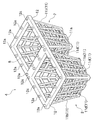
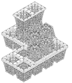
- FIG. 1 is a perspective view of a storage unit according to an embodiment as viewed from above.
- the storage unit 1 includes a structure 4 composed of a plurality of bowl-shaped blocks 2 and a reinforcing frame 6 composed of four square frame portions.
- FIG. 2 is a perspective view of the structure 4 constituting the storage unit 1 according to the embodiment as viewed from above
- FIG. 3 is a perspective view of the structure 4 as viewed from below
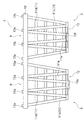
- FIG. 4 is the figure which looked at this from the side.
- the structure 4 is a member configured with the two ridge-like blocks 2 as a minimum unit, and is formed by injection molding of polypropylene.
- Each bowl-shaped block 2 constituting the structure 4 has an opening 8 on the upper side and a bottom 10 having a smaller area than the opening 8 on the lower side.
- the periphery of the bowl-shaped block 2 is surrounded by a side wall 11 that is inclined outwardly upward.
- a flange 12 is formed by connecting two rectangular frames.
- a plurality of projections 12a projecting in the opposite direction to the bottom portion 10 are formed so as to surround each opening 8 at a predetermined interval.
- the bottom portion 10 is a portion that closes the bottom of the bowl-shaped block 2 in a state where liquid can flow in, and has a plurality of through holes 10a through which liquid can flow. Further, in the center of the bottom portion 10, when the storage units 1 are stacked, a connection portion that connects the bottom portions 10 up and down is formed.
- one bowl-shaped block 2 is arranged from the bottom 10 to the outside of the bowl-shaped block 2.
- the other hook-shaped block 2 includes a concave part 10f embedded in the hook-shaped block 2 from the bottom part 10 as a connecting part.
- the connecting portion is supported by a plurality of rib members so that it can be positioned at the center of the bottom portion 10.
- the side wall 11 is a wall having a plurality of through holes 11a through which liquid can flow.
- the side walls 11 are respectively positioned below the four sides constituting the flange portion 12, and are inclined outward from the bottom portion 10 toward the flange portion 12.
- the side wall 11 is comprised by the some pillar part 11b and the trunk
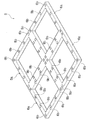
- FIG. 5 is a plan view of the reinforcing frame constituting the storage unit 1 according to the embodiment
- FIG. 6 is a perspective view of the reinforcing frame as viewed from above.
- the reinforcing frame 6 has a structure in which four square frame portions 6a are connected, and is formed by injection molding polypropylene.
- each frame portion 6 a has a shape corresponding to the flange portion 12.
- the four frame portions 6a are connected such that two of the four sides constituting the frame portion 6a are connected to two sides of the other frame portion 6a, and a cross-shaped rib is formed at the center. It is configured in a square frame shape.
- recessed portions 6 b for receiving the protruding portions 12 a are provided at predetermined intervals so as to surround the respective frame portions 6 a.
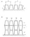
- a procedure for constructing a rainwater reservoir using the storage unit 1 according to the embodiment will be described by taking as an example a case where a rainwater reservoir is constructed by stacking even-numbered structures 4.
- the description is limited to the construction of the rainwater storage tank, and therefore, the steps for arranging the additional components such as the laying of the bottom protective sheet and the connection of the water supply pipe are omitted.
- the worker places the saddle-like block 2 on the bottom surface of the excavated ground so that the opening 8 is on the upper side.
- the bowl-shaped blocks 2 positioned at the lowermost stage the bowl-shaped block 2 having the convex portion 10e on the bottom portion 10 is placed after the convex portion 10e is cut.
- the height of the bottom part 10 and the flange part 12 of the bowl-shaped block 2 located in the lowest step can be arrange
- the worker positions the recess 6b (see FIGS. 5 and 6) formed on the reinforcing frame 6 at the position of the protrusion 12a (see FIGS. 2 and 4) formed on the flange 12 of the bowl-shaped block 2.
- the reinforcing frame 6 is placed on the bowl-shaped block 2 in accordance with As a result, the protrusion 12 a is fitted into the recess 6 b and the reinforcing frame 6 is fixed on the structure 4.
- the worker puts the bowl-shaped block 2 on the reinforcing frame 6 so that the opening 8 is on the lower side.
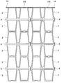
- the worker connects the plurality of reinforcing frames 6 in the horizontal direction by covering the structure 4 across the two reinforcing frames 6, for example, as shown in FIG. 8. .
- the worker places the opening 8 on the upper side of the bowl-shaped block 2 placed on the reinforcing frame 6 with the opening 8 on the lower side.
- the bowl-shaped block 2 is placed.
- the worker overlaps the bowl-shaped block 2 in which the concave portion 10f is formed in the bottom portion 10 on the bowl-shaped block 2 in which the convex portion 10e is formed in the bottom portion 10, and the concave portion 10f is formed in the bottom portion 10.
- the bowl-shaped block 2 in which the convex part 10e is formed on the bottom part 10 is overlapped. Thereby, the convex part 10e is engage
- the bowl-shaped block 2 having the convex portion 10e on the bottom portion 10 can be placed after the convex portion 10e is cut.
- the height of the bottom part 10 and the flange part 12 of the bowl-shaped block 2 located in the uppermost stage can be arrange
- the plurality of storage units 1 are firmly connected to each other by connecting the storage units 1 horizontally by covering the two reinforcing frames 6 and covering the bowl-shaped blocks 2. Can do.
- the storage units 1 can be connected to each other with a simple structure by connecting the plurality of structures 4 using the reinforcing frame 6 regardless of the joint member as in the past. For this reason, the horizontal strength of the storage unit 1 can be enhanced. Moreover, since a joint member is not used, the number of parts constituting the rainwater storage tank can be reduced, and the rainwater storage tank can be constructed at low cost.
- the reinforcing frame 6 has a structure in which four square frame portions 6 a are connected and the structure 4 is composed of two bowl-shaped blocks 2, the structure 4 straddles the two reinforcing frames 6. Even if the reinforcing frames 6 are connected to each other by covering, the structure 4 will not be excessive or deficient.
- the direction of the structures 4 arranged at both ends of the rainwater storage tank is arranged so as to be orthogonal to the direction of the other structures 4, thereby reinforcing the structure.
- the structure 4 can be arranged according to the shape of the frame 6.
- the storage unit 1 can be simply connected, without using a joint member, for example, as shown in FIG. It is possible to connect.
- the rainwater reservoir is constructed by stacking the even-numbered structures 4
- the rainwater reservoir is constructed by stacking the odd-numbered structures 4. You can also.
- the worker places the reinforcing frame 6 on the bottom surface of the excavated ground so that the opening 8 is on the lower side of the reinforcing frame 6. Cover the bowl-shaped block 2.
- the rainwater water tank which consists of the storage unit 1 which consists of only one step is constructed. It is also possible to do. For this reason, it is possible to embed a rainwater reservoir even when the depth in the ground is shallow. Moreover, since the storage unit 1 is comprised using the reinforcement frame 6 with a strong horizontal strength, a rainwater storage tank can be embed
- the bowl-shaped block 2 contained in one structure 4 may be provided with the same kind of connection part. That is, as shown in FIG. 13A, the structure 4 having only the bowl-shaped block 2 provided with the convex part 10e, and only the bowl-shaped block 2 provided with the concave part 10f as shown in FIG. 13B. There may be a structure 4 having Also in this case, in the same procedure as described with reference to FIGS. 7 to 9, the bowl-shaped block in which the concave section 10f is formed in the bottom section 10 on the bowl-shaped block 2 in which the convex section 10e is formed in the bottom section 10 is used.
- the rainwater storage tank is constructed by repeating 2 or overlapping the bowl-shaped block 2 having the convex part 10e formed on the bottom part 10 on the bowl-shaped block 2 having the concave part 10f formed on the bottom part 10.
- the structure 4 having the bowl-shaped block 2 provided with the concave portion 10f is used in the lowermost stage or the uppermost stage, the structure 4 that is easily located in the lowermost stage or the uppermost stage without cutting the convex portion 10e.
- the height of the bottom part 10 and the flange part 12 can be made uniform.
- the convex portion 10e By fitting the convex portion 10e into the concave portion 10f, the bowl-shaped blocks 2 can be stacked up and down so as not to be displaced in the horizontal direction.
- the structure 4 and the reinforcing frame 6 are not limited to polypropylene and may be formed of other thermoplastic resins.
- the structure 4 and the reinforcing frame 6 may be generated by a method other than injection molding.
- the structure 4 does not necessarily have to be composed of the two bowl-shaped blocks 2.
- the top plate 14 when constructing a rainwater reservoir, may be attached to the uppermost structure 4 constituting the rainwater reservoir.
- the top plate 14 is a substantially rectangular member in plan view having two openings 14 a, and each of the openings 14 a has the same size as the bottom 10 of the bowl-shaped block 2. . After cutting the convex portion 10e, the top plate 14 is attached to the uppermost structure 4 constituting the rainwater storage tank so that the bottom portion 10 fits into the opening, whereby the rainwater storage water as shown in FIG.
- the upper surface of the tank can be planar.
- the reinforcing frame 6 may have a shape in which thin members are combined. That is, a plurality of concave portions surrounded by a thin side wall and a thin bottom surface may be formed in the reinforcing frame 6, and ribs that reinforce the strength of the reinforcing frame 6 may be appropriately formed in the concave portion.
- the reinforcing frame 6 can be a lightweight and high-strength member, and in particular, the horizontal strength can be enhanced.
- the recessed portion 6b may use a recessed portion located at a position corresponding to the position of the protruding portion 12a when the flange portion 12 is superimposed on the reinforcing frame 6.
- the flange portion 12 may have a shape combining thin members. That is, the flange portion 12 may be formed with a plurality of concave portions surrounded by a thin side wall and a thin bottom surface, and ribs that reinforce the proof strength of the flange portion 12 may be appropriately formed in the concave portion.
- the cross-sectional shape of the recessed part 6b formed in the reinforcement frame 6 is a rectangle is demonstrated to an example, the cross-sectional shape of the recessed part 6b is circular. Also good.
Landscapes
- Engineering & Computer Science (AREA)
- Health & Medical Sciences (AREA)
- Life Sciences & Earth Sciences (AREA)
- Hydrology & Water Resources (AREA)
- Public Health (AREA)
- Water Supply & Treatment (AREA)
- Environmental & Geological Engineering (AREA)
- Structural Engineering (AREA)
- Sewage (AREA)
Abstract
[課題]互いを堅固に連結できると共に、さまざまな深度に合わせた雨水貯留槽を構築することが可能な貯留ユニットを提供する。 [解決手段]液体の流入出が可能な複数の籠状ブロックから成る構造物と前記構造物によって水平方向に連結される補強枠を備えた貯留ユニットであって、前記籠状ブロックは、底部と、前記底部の反対側に開放された開口の周縁に形成され、前記底部と反対方向に突出する複数の突起部を備えた枠状のフランジ部と、前記底部から前記フランジ部に向かって外側に傾斜する側壁とを備え、前記補強枠は、前記フランジ部に対応する形状を有し、前記フランジ部に前記突起部を受け入れる窪状部が設けられた少なくとも四個の枠部分を連結して形成され、前記突起部を前記窪状部に挿入して前記籠状ブロックから成る前記構造物と前記補強枠とを接続する場合において、二個の前記補強枠を跨いで前記構造物を前記補強枠に接続することにより複数の前記補強枠が水平方向に連結される。
Description
本発明は、雨水等を貯留する籠状のブロックを組み合わせてなる貯留ユニットに関するものである。
従来より、雨水等の液体の流入出が可能な複数の籠型の構造部材を、継手部材を用いて連結した構造物が知られている(例えば、特許文献1)。この構造物によれば、構造部材を連結するのにボルトや溶接等を用いる必要がないため、構造物を短期間で構築することができる。なお、特許文献1においては、この構造物を用いて道路や橋を構築する場合を例に挙げているが、この構造物を多数組み合わせることにより、地中に埋設して用いられる雨水貯留槽を構築することも可能である。
しかしながら、上述の構造物においては、多くの継手部材を用いなければ構造物材同士を互いに連結できないため、連結構造が複雑になり、特に水平方向において構造物同士を堅固に連結することが難しかった。
また、上述の構造物を用いて構築された雨水貯留槽を地中に埋設する場合、継手部材を介して水平方向の土圧を担うため、水平方向の耐力が脆弱になるという問題があった。特に、水平方向の土圧は、雨水貯留槽が埋設される地中の深さが深くなるほど大きくなることから、上述の構造物を用いた場合には、雨水貯留槽を比較的浅い位置までしか埋設できなかった。一方で、継手部材を介して水平方向の土圧を担う場合、構造物を一段で水平方向に連結して雨水貯留槽を構築した場合も水平方向の耐力を確保することが難しかった。
本発明の目的は、互いを堅固に連結できると共に、さまざまな深度に合わせた雨水貯留槽を構築することが可能な貯留ユニットを提供することである。
本発明の目的は、互いを堅固に連結できると共に、さまざまな深度に合わせた雨水貯留槽を構築することが可能な貯留ユニットを提供することである。
本発明の貯留ユニットは、
液体の流入出が可能な複数の籠状ブロックから成る構造物と前記構造物によって水平方向に連結される補強枠を備えた貯留ユニットであって、
前記籠状ブロックが、
底部と、
前記底部の反対側に開放された開口の周縁に形成され、前記底部と反対方向に突出する複数の突起部を備えた枠状のフランジ部と、
前記底部から前記フランジ部に向かって外側に傾斜する側壁とを備え、
前記補強枠が、
前記フランジ部に対応する形状を有し、前記フランジ部に前記突起部を受け入れる窪状部が設けられた少なくとも四個の枠部分を連結して形成され、
前記突起部を前記窪状部に挿入して前記籠状ブロックから成る前記構造物と前記補強枠とを接続する場合において、二個の前記補強枠を跨いで前記構造物を前記補強枠に接続することにより複数の前記補強枠が水平方向に連結されることを特徴とする。
液体の流入出が可能な複数の籠状ブロックから成る構造物と前記構造物によって水平方向に連結される補強枠を備えた貯留ユニットであって、
前記籠状ブロックが、
底部と、
前記底部の反対側に開放された開口の周縁に形成され、前記底部と反対方向に突出する複数の突起部を備えた枠状のフランジ部と、
前記底部から前記フランジ部に向かって外側に傾斜する側壁とを備え、
前記補強枠が、
前記フランジ部に対応する形状を有し、前記フランジ部に前記突起部を受け入れる窪状部が設けられた少なくとも四個の枠部分を連結して形成され、
前記突起部を前記窪状部に挿入して前記籠状ブロックから成る前記構造物と前記補強枠とを接続する場合において、二個の前記補強枠を跨いで前記構造物を前記補強枠に接続することにより複数の前記補強枠が水平方向に連結されることを特徴とする。
このように、二個の補強枠を跨いで構造物を補強枠に接続することにより、複数の貯留ユニットを互いに堅固に連結することができる。また、従来のように継手部材によらず、補強枠を用いて複数の構造物を接続することにより、簡易な構造で貯留ユニット同士を接続でき、貯留ユニットの水平方向の耐力を強化することができる。また、継手部材を用いないため、雨水貯留槽を構成する部品の点数を減らすことができ、低コストで雨水貯留槽を構築することができる。
また、本発明の貯留ユニットは、
前記構造物が、前記底面に凸部が形成された前記籠状ブロックと、前記底面に凹部形成された前記籠状ブロックの少なくとも一方を備え、
前記開口を下側にした前記籠状ブロックの上に前記開口を上側にして前記籠状ブロックを積み重ねた場合に、前記凹部に前記凸部が嵌め込まれて前記籠状ブロック同士が上下方向に接続されることを特徴とする。
前記構造物が、前記底面に凸部が形成された前記籠状ブロックと、前記底面に凹部形成された前記籠状ブロックの少なくとも一方を備え、
前記開口を下側にした前記籠状ブロックの上に前記開口を上側にして前記籠状ブロックを積み重ねた場合に、前記凹部に前記凸部が嵌め込まれて前記籠状ブロック同士が上下方向に接続されることを特徴とする。
このように、凸部または凹部が形成された籠状ブロックを上下に接続することにより、継手部材に形成された繊細な構造の突起等を介して籠状ブロックを接続する場合と比較して、より堅固に籠状ブロック同士を上下に連結することができる。
また、本発明の貯留ユニットは、
前記構造物が、前記底面に凸部が形成された前記籠状ブロックと、前記底面に凹部形成された前記籠状ブロックとをそれぞれ備えることを特徴とする。
このように、籠状ブロックの底面に簡易な構造の凸部と凹部を形成して籠状ブロック同士を上下に接続することによりさらに堅固に籠状ブロック同士を上下に連結することができる。
また、本発明の貯留ユニットは、
前記構造物が、前記底面に凸部が形成された前記籠状ブロックと、前記底面に凹部形成された前記籠状ブロックとをそれぞれ備えることを特徴とする。
このように、籠状ブロックの底面に簡易な構造の凸部と凹部を形成して籠状ブロック同士を上下に接続することによりさらに堅固に籠状ブロック同士を上下に連結することができる。
また、本発明の貯留ユニットは、
前記補強枠を構成する部材が、熱可塑性樹脂であることを特徴とする。
前記補強枠を構成する部材が、熱可塑性樹脂であることを特徴とする。
本発明の貯留ユニットによれば、互いを堅固に連結できると共に、さまざまな深度に合わせた雨水貯留槽を構築することができる。
以下、図面を参照して、実施の形態に係る貯留ユニットについて、雨水貯水槽を構成するのに用いられる貯留ユニットを例に説明する。図1は、実施の形態に係る貯留ユニットを上方から視た斜視図である。図1に示すように、貯留ユニット1は、複数の籠状ブロック2から成る構造物4と、四個の正方形状の枠部分から成る補強枠6とによって構成される。
図2は、実施の形態に係る貯留ユニット1を構成する構造物4を上方から視た斜視図であり、図3は、これを下方から視た斜視図である。また、図4は、これを側方から視た図である。図2~4に示すように、構造物4は、二個の籠状ブロック2を最小単位として構成された部材であり、ポリプロピレンを射出成型して形成されている。構造物4を構成するそれぞれの籠状ブロック2は、上方に開口部8を有し、下方に開口部8よりも面積の小さな底部10を有している。また、籠状ブロック2の周囲は、上方に向かって外側に傾斜した側壁11によって囲まれている。
開口部8を囲んだ側壁11の上端には、二つの矩形状の枠を連結したフランジ部12が形成されている。フランジ部12の上面には、底部10と反対方向に突出する複数の突起部12aが所定の間隔でそれぞれの開口部8を囲んで形成されている。
底部10は、籠状ブロック2の底を液体の流入が可能な状態で塞ぐ部位であり、液体の流入が可能な複数の通孔10aを有している。また、底部10の中央には、貯留ユニット1を積み重ねる場合に、底部10同士を上下に接続する接続部が形成されている。
ここで、図2~4に示すように、貯留ユニット1を構成する構造物4が二個の籠状ブロック2から成る場合、一方の籠状ブロック2は、底部10から籠状ブロック2の外側に突出する凸部10eを接続部として備え、他方の籠状ブロック2は、底部10から籠状ブロック2の内側に埋没する凹部10fを接続部として備えている。なお、接続部は、底部10の中央部に位置することができるように複数のリブ材によって支持されている。
側壁11は、液体の流入が可能な複数の通孔11aを有する壁である。側壁11は、フランジ部12を構成する四辺の下方にそれぞれ位置し、底部10からフランジ部12に向かって外側に傾斜している。なお、側壁11は、それぞれ複数の柱部11bと胴縁部11dによって構成されている。
図5は、実施の形態に係る貯留ユニット1を構成する補強枠の平面図であり、図6は、これを上方から視た斜視図である。図5、6に示すように、補強枠6は、四個の正方形状の枠部分6aを連結した構造を有し、ポリプロピレンを射出成型して形成されている。ここで、各々の枠部分6aは、フランジ部12に対応する形状を有している。また、四個の枠部分6aは、それぞれ枠部分6aを構成する四辺のうちの二辺が他の枠部分6aの二辺と接続されており、中央に十字状のリブが形成されるようにして正方形枠状に構成されている。
また、補強枠6の表面及び裏面には、それぞれの枠部分6aを囲むようにして、突起部12a(図2、4参照)を受け入れるための窪状部6bが所定の間隔で設けられている。
また、補強枠6の表面及び裏面には、それぞれの枠部分6aを囲むようにして、突起部12a(図2、4参照)を受け入れるための窪状部6bが所定の間隔で設けられている。
次に、実施の形態に係る貯留ユニット1を用いて雨水貯水槽を構築する手順について、偶数段の構造物4を積み重ねて雨水貯水槽を構築する場合を例に説明する。なお、以下の説明では、説明内容を雨水貯水槽の構築のみに絞るため、底面保護シートの敷設や給水管の接続などの付随的な部品の配置手順については省略する。
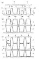
まず、作業員は、図7(a)に示すように、掘削された地盤の底面に籠状ブロック2を開口部8が上側になるようにして載置する。ここで、最下段に位置する籠状ブロック2のうち、底部10に凸部10eを有する籠状ブロック2は、凸部10eをカットした上で載置される。これにより、最下段に位置する籠状ブロック2の底部10、フランジ部12の高さを揃えることができる。
次に、作業員は、補強枠6に形成された窪状部6b(図5、6参照)の位置を籠状ブロック2のフランジ部12に形成された突起部12a(図2、4参照)の位置に合わせ、籠状ブロック2の上に補強枠6を載置する。これにより、突起部12aが窪状部6bに嵌め込まれ、補強枠6が構造物4上に固定される。
次に、作業員は、図7(b)に示すように、さらに補強枠6の上に開口部8が下側になるようにして籠状ブロック2を被せる。ここで、籠状ブロック2を被せる場合、作業員は、たとえば図8に示すように、二個の補強枠6を跨いで構造物4を被せることにより複数の補強枠6を水平方向に連結させる。
次に、作業員は、図7(c)に示すように、開口部8を下側にして補強枠6に載置された籠状ブロック2の上に、さらに開口部8を上側にした状態の籠状ブロック2を載置する。この場合、作業員は、凸部10eが底部10に形成された籠状ブロック2の上に凹部10fが底部10に形成された籠状ブロック2を重ね、かつ凹部10fが底部10に形成された籠状ブロック2の上に凸部10eが底部10に形成された籠状ブロック2を重ねる。これにより、凹部10fに凸部10eが嵌め込まれ、開口部8の向きを反対にした籠状ブロック2同士を水平方向に位置ずれしないように上下に積載することができる。
以下、同様の作業を繰り返すことにより、図9に示すように、複数層の籠状ブロック2から成る雨水貯水槽を構築することができる。なお、最上段に位置する籠状ブロック2のうち、底部10に凸部10eを有する籠状ブロック2は、凸部10eをカットした上で載置することもできる。これにより、最上段に位置する籠状ブロック2の底部10、フランジ部12の高さを揃えることができる。
この実施の形態に係る発明によれば、二個の補強枠6を跨いで籠状ブロック2を被せて貯留ユニット1を水平に接続することにより、複数の貯留ユニット1を互いに堅固に連結することができる。また、従来のように継手部材によらず、補強枠6を用いて複数の構造物4を接続することにより、簡易な構造で貯留ユニット1同士を接続できる。このため、貯留ユニット1の水平方向の耐力を強化することができる。また、継手部材を用いないため、雨水貯留槽を構成する部品の点数を減らすことができ、低コストで雨水貯留槽を構築することができる。
この実施の形態に係る発明によれば、二個の補強枠6を跨いで籠状ブロック2を被せて貯留ユニット1を水平に接続することにより、複数の貯留ユニット1を互いに堅固に連結することができる。また、従来のように継手部材によらず、補強枠6を用いて複数の構造物4を接続することにより、簡易な構造で貯留ユニット1同士を接続できる。このため、貯留ユニット1の水平方向の耐力を強化することができる。また、継手部材を用いないため、雨水貯留槽を構成する部品の点数を減らすことができ、低コストで雨水貯留槽を構築することができる。
また、補強枠6が四個の正方形状の枠部分6aを連結した構造を有し、構造物4が二個の籠状ブロック2から成るため、二個の補強枠6を跨いで構造物4を被せることにより補強枠6同士を連結しても構造物4に過不足が生じることがない。たとえば、図10(a)、(b)に示すように、雨水貯留槽の両端部に配置する構造物4の方向をそれ以外の構造物4の方向と直交するように配置することにより、補強枠6の形状に合わせて構造物4を配置することができる。
また、この実施の形態に係る発明によれば、継手部材を用いることなく、簡易に貯留ユニット1を連結することができるため、たとえば、図11に示すように、複雑な形状で貯留ユニット1を連結することが可能である。
なお、上述の実施の形態では、偶数段の構造物4を積み重ねて雨水貯水槽を構築する場合を例に説明しているが、奇数段の構造物4を積み重ねて雨水貯水槽を構築することもできる。この場合まず、作業員は、図12(a)に示すように、掘削された地盤の底面に補強枠6を載置し、補強枠6の上に開口部8が下側になるようにして籠状ブロック2を被せる。
以下、偶数段の構造物4を積み重ねる場合と同様に、補強枠6と構造物4とを交互に積み重ねることを繰り返し、図12(b)に示すように、所定の層厚を有する雨水貯水槽が完成する。
ところで、本発明によれば、継手部材に代えて補強枠6が水平方向の土圧を担うため、図12(a)に示すように、一段のみから成る貯留ユニット1から成る雨水貯水槽を構築することも可能である。このため、地中の深度が浅くても雨水貯水槽を埋設することができる。また、水平方向の耐力が強い補強枠6を用いて貯留ユニット1が構成されるため、掘削された地盤の底面を深くしても雨水貯水槽を埋設することができる。よって、構造物4を適宜偶数段または奇数段に積み重ねることで、さまざまな深度に合わせた雨水貯留槽を構築することができる。
また、上述の実施の形態において、一つの構造物4に含まれる籠状ブロック2が同種の接続部を備えていてもよい。すなわち、図13(a)に示すように、凸部10eを備えた籠状ブロック2のみを有する構造物4と、図13(b)に示すように、凹部10fを備えた籠状ブロック2のみを有する構造物4があってもよい。この場合においても、図7~9を用いて説明したのと同様の手順で、凸部10eが底部10に形成された籠状ブロック2の上に凹部10fが底部10に形成された籠状ブロック2を重ね、または凹部10fが底部10に形成された籠状ブロック2の上に凸部10eが底部10に形成された籠状ブロック2を重ねることを繰り返しながら雨水貯留槽が構築される。
なお、凹部10fを備えた籠状ブロック2を有する構造物4のみを最下段または最上段に使用する場合、凸部10eをカットすることなく容易に最下段または最上段に位置する構造物4の底部10、フランジ部12の高さを揃えることができる。
このように、凸部10eを備えた籠状ブロック2のみを有する構造物4と、凹部10fを備えた籠状ブロック2のみを有する構造物4を使用して雨水貯留槽を構築する場合においても、凹部10fに凸部10eを嵌め込むことにより、籠状ブロック2同士が水平方向に位置ずれしないように上下に積載することができる。
また、上述の実施の形態において、一つの構造物4に含まれる籠状ブロック2が同種の接続部を備えていてもよい。すなわち、図13(a)に示すように、凸部10eを備えた籠状ブロック2のみを有する構造物4と、図13(b)に示すように、凹部10fを備えた籠状ブロック2のみを有する構造物4があってもよい。この場合においても、図7~9を用いて説明したのと同様の手順で、凸部10eが底部10に形成された籠状ブロック2の上に凹部10fが底部10に形成された籠状ブロック2を重ね、または凹部10fが底部10に形成された籠状ブロック2の上に凸部10eが底部10に形成された籠状ブロック2を重ねることを繰り返しながら雨水貯留槽が構築される。
なお、凹部10fを備えた籠状ブロック2を有する構造物4のみを最下段または最上段に使用する場合、凸部10eをカットすることなく容易に最下段または最上段に位置する構造物4の底部10、フランジ部12の高さを揃えることができる。
このように、凸部10eを備えた籠状ブロック2のみを有する構造物4と、凹部10fを備えた籠状ブロック2のみを有する構造物4を使用して雨水貯留槽を構築する場合においても、凹部10fに凸部10eを嵌め込むことにより、籠状ブロック2同士が水平方向に位置ずれしないように上下に積載することができる。
また、上述の実施の形態において、構造物4および補強枠6は、ポリプロピレンに限らず他の熱可塑性樹脂で形成されていてもよい。また、構造物4や補強枠6は、射出成型以外の方法で生成されてもよい。
また、上述の実施の形態において、構造物4は、必ずしも二個の籠状ブロック2から構成されていなくてもよい。たとえば、3個の籠状ブロック2から成るL字型の固形状を有していてもよい。また、4個の籠状ブロック2から構成され、各籠状ブロック2が補強枠6を構成する各枠部分6aと対応するようにしてもよい。
また、上述の実施の形態においては、継手部材を用いなくても雨水貯水槽を構築することができることを説明しているが、継手部材を用いて雨水貯水槽を構築することも可能である。補強枠6に加えてさらに継手部材を用いることにより、より強固な雨水貯水槽を構築することができる。
また、上述の実施の形態において、図14に示すように、雨水貯水槽を構築する際に、雨水貯水槽を構成する最上段の構造物4に天板14を取り付けてもよい。ここで、天板14は、二つの開口部14aを有する平面視略矩形状の部材であり、開口部14aは、それぞれ、籠状ブロック2の底部10と同程度の大きさを有している。凸部10eをカットした後、この天板14を、開口部に底部10が嵌るようにして雨水貯水槽を構成する最上段の構造物4に取り付けることにより、図15に示すように、雨水貯水槽の上面を平面状にすることができる。
また、上述の実施の形態において、図14に示すように、雨水貯水槽を構築する際に、雨水貯水槽を構成する最上段の構造物4に天板14を取り付けてもよい。ここで、天板14は、二つの開口部14aを有する平面視略矩形状の部材であり、開口部14aは、それぞれ、籠状ブロック2の底部10と同程度の大きさを有している。凸部10eをカットした後、この天板14を、開口部に底部10が嵌るようにして雨水貯水槽を構成する最上段の構造物4に取り付けることにより、図15に示すように、雨水貯水槽の上面を平面状にすることができる。
また、上述の実施の形態において、補強枠6は、薄肉の部材を組み合わせた形状を有していてもよい。すなわち、補強枠6に、薄肉の側壁と薄肉の底面によって囲まれた複数の凹状部分が形成され、凹状部分内には適宜補強枠6の耐力を補強するリブが形成されていてもよい。
これにより、補強枠6を軽量で高強度の部材とすることができ、特に水平方向の耐力を強化することができる。なおこの場合、窪状部6bは、補強枠6にフランジ部12を重ね合わせた場合において、突起部12aの位置に対応する位置に位置する凹状部分を利用したものであってもよい。
同様に、フランジ部12が、薄肉の部材を組み合わせた形状を有していてもよい。すなわち、フランジ部12に、薄肉の側壁と薄肉の底面によって囲まれた複数の凹状部分が形成され、凹状部分内には適宜フランジ部12の耐力を補強するリブが形成されていてもよい。
また、上述の実施の形態においては、補強枠6に形成された窪状部6bの断面形状が矩形である場合を例に説明しているが、窪状部6bの断面形状は円形であってもよい。
1 貯留ユニット
2 籠状ブロック
4 構造物
6 補強枠
6a 枠部分
6b 窪状部
8 開口部
10 底部
10a 通孔
10e 凸部
10f 凹部
11 側壁
11a 通孔
11b 柱部
11d 胴縁部
12 フランジ部
12a 突起部
14 天板
14a 開口部
2 籠状ブロック
4 構造物
6 補強枠
6a 枠部分
6b 窪状部
8 開口部
10 底部
10a 通孔
10e 凸部
10f 凹部
11 側壁
11a 通孔
11b 柱部
11d 胴縁部
12 フランジ部
12a 突起部
14 天板
14a 開口部
Claims (4)
- 液体の流入出が可能な複数の籠状ブロックから成る構造物と前記構造物によって水平方向に連結される補強枠を備えた貯留ユニットであって、
前記籠状ブロックは、
底部と、
前記底部の反対側に開放された開口の周縁に形成され、前記底部と反対方向に突出する複数の突起部を備えた枠状のフランジ部と、
前記底部から前記フランジ部に向かって外側に傾斜する側壁とを備え、
前記補強枠は、
前記フランジ部に対応する形状を有し、前記フランジ部に前記突起部を受け入れる窪状部が設けられた少なくとも四個の枠部分を連結して形成され、
前記突起部を前記窪状部に挿入して前記籠状ブロックから成る前記構造物と前記補強枠とを接続する場合において、二個の前記補強枠を跨いで前記構造物を前記補強枠に接続することにより複数の前記補強枠が水平方向に連結されることを特徴とする貯留ユニット。 - 前記構造物は、前記底面に凸部が形成された前記籠状ブロックと、前記底面に凹部形成された前記籠状ブロックの少なくとも一方を備え、
前記開口を下側にした前記籠状ブロックの上に前記開口を上側にして前記籠状ブロックを積み重ねた場合に、前記凹部に前記凸部が嵌め込まれて前記籠状ブロック同士が上下方向に接続されることを特徴とする請求項1記載の貯留ユニット。 - 前記構造物は、前記底面に凸部が形成された前記籠状ブロックと、前記底面に凹部形成された前記籠状ブロックとをそれぞれ備えることを特徴とする請求項2記載の貯留ユニット。
- 前記補強枠を構成する部材は、熱可塑性樹脂であることを特徴とする請求項1または2記載の貯留ユニット。
Priority Applications (1)
| Application Number | Priority Date | Filing Date | Title |
|---|---|---|---|
| JP2018502996A JP6629423B2 (ja) | 2016-02-29 | 2017-02-10 | 貯留ユニット |
Applications Claiming Priority (2)
| Application Number | Priority Date | Filing Date | Title |
|---|---|---|---|
| JP2016036885 | 2016-02-29 | ||
| JP2016-036885 | 2016-02-29 |
Publications (1)
| Publication Number | Publication Date |
|---|---|
| WO2017150138A1 true WO2017150138A1 (ja) | 2017-09-08 |
Family
ID=59743807
Family Applications (1)
| Application Number | Title | Priority Date | Filing Date |
|---|---|---|---|
| PCT/JP2017/004867 Ceased WO2017150138A1 (ja) | 2016-02-29 | 2017-02-10 | 貯留ユニット |
Country Status (3)
| Country | Link |
|---|---|
| JP (1) | JP6629423B2 (ja) |
| TW (1) | TWI716542B (ja) |
| WO (1) | WO2017150138A1 (ja) |
Cited By (4)
| Publication number | Priority date | Publication date | Assignee | Title |
|---|---|---|---|---|
| JP2019141228A (ja) * | 2018-02-19 | 2019-08-29 | 帝人株式会社 | 簡易床および簡易ベッド用ユニット |
| JP2019199713A (ja) * | 2018-05-15 | 2019-11-21 | 城東リプロン株式会社 | 管状ブロック、及び、管状ブロック構造体 |
| KR102339506B1 (ko) * | 2021-04-15 | 2021-12-16 | 충청대학교 산학협력단 | 우수 재활용형 시티댐 |
| WO2022107173A1 (en) * | 2020-11-18 | 2022-05-27 | Ross S.R.L. | System for up-taking, collecting and distributing meteoric waters |
Citations (4)
| Publication number | Priority date | Publication date | Assignee | Title |
|---|---|---|---|---|
| JP2009057695A (ja) * | 2007-08-30 | 2009-03-19 | Hayashi Bussan Hatsumei Kenkyusho:Kk | テーブル状単位部材およびそれを用いる雨水等の貯留浸透施設 |
| JP2012158864A (ja) * | 2011-01-28 | 2012-08-23 | Ihi Infrastructure Systems Co Ltd | 貯水空間形成ブロック |
| JP2014109140A (ja) * | 2012-12-03 | 2014-06-12 | Takiron Co Ltd | 地下水槽用充填部材の継手構造 |
| JP2015096680A (ja) * | 2013-11-15 | 2015-05-21 | 天昇電気工業株式会社 | 籠構造物、貯水ユニットおよび貯水槽 |
Family Cites Families (3)
| Publication number | Priority date | Publication date | Assignee | Title |
|---|---|---|---|---|
| CN201254741Y (zh) * | 2008-07-31 | 2009-06-10 | 北京泰宁科创科技有限公司 | 一种储水池用塑料模块 |
| AU2012373593B2 (en) * | 2012-03-14 | 2017-08-24 | Sekisui Techno Molding Co., Ltd. | Structural member used in rainwater storage laminated structure |
| CN204940402U (zh) * | 2015-05-14 | 2016-01-06 | 积水技术成型株式会社 | 用于雨水储存层叠结构体的结构部件 |
-
2017
- 2017-02-10 WO PCT/JP2017/004867 patent/WO2017150138A1/ja not_active Ceased
- 2017-02-10 JP JP2018502996A patent/JP6629423B2/ja active Active
- 2017-02-16 TW TW106105044A patent/TWI716542B/zh active
Patent Citations (4)
| Publication number | Priority date | Publication date | Assignee | Title |
|---|---|---|---|---|
| JP2009057695A (ja) * | 2007-08-30 | 2009-03-19 | Hayashi Bussan Hatsumei Kenkyusho:Kk | テーブル状単位部材およびそれを用いる雨水等の貯留浸透施設 |
| JP2012158864A (ja) * | 2011-01-28 | 2012-08-23 | Ihi Infrastructure Systems Co Ltd | 貯水空間形成ブロック |
| JP2014109140A (ja) * | 2012-12-03 | 2014-06-12 | Takiron Co Ltd | 地下水槽用充填部材の継手構造 |
| JP2015096680A (ja) * | 2013-11-15 | 2015-05-21 | 天昇電気工業株式会社 | 籠構造物、貯水ユニットおよび貯水槽 |
Cited By (5)
| Publication number | Priority date | Publication date | Assignee | Title |
|---|---|---|---|---|
| JP2019141228A (ja) * | 2018-02-19 | 2019-08-29 | 帝人株式会社 | 簡易床および簡易ベッド用ユニット |
| JP7028670B2 (ja) | 2018-02-19 | 2022-03-02 | 帝人株式会社 | 簡易床および簡易ベッド用ユニット |
| JP2019199713A (ja) * | 2018-05-15 | 2019-11-21 | 城東リプロン株式会社 | 管状ブロック、及び、管状ブロック構造体 |
| WO2022107173A1 (en) * | 2020-11-18 | 2022-05-27 | Ross S.R.L. | System for up-taking, collecting and distributing meteoric waters |
| KR102339506B1 (ko) * | 2021-04-15 | 2021-12-16 | 충청대학교 산학협력단 | 우수 재활용형 시티댐 |
Also Published As
| Publication number | Publication date |
|---|---|
| TWI716542B (zh) | 2021-01-21 |
| JPWO2017150138A1 (ja) | 2018-12-13 |
| TW201734281A (zh) | 2017-10-01 |
| JP6629423B2 (ja) | 2020-01-15 |
Similar Documents
| Publication | Publication Date | Title |
|---|---|---|
| JP6629423B2 (ja) | 貯留ユニット | |
| JP5384757B2 (ja) | 貯留複合体並びにこれを用いた貯留槽及び貯留浸透槽 | |
| JP5294439B1 (ja) | 雨水貯留積層構造体に用いる構造部材 | |
| JPH10266313A (ja) | 雨水等の貯留及び浸透施設用充填体 | |
| JP5392940B1 (ja) | 雨水貯留積層構造体に用いる構造部材 | |
| MX2014005032A (es) | Accesorio moldeado por inyeccion con tejido a doble cara. | |
| JP5700742B2 (ja) | 構築物および構築物を用いた雨水等の流出抑制施設 | |
| JP2014111877A (ja) | 壁体構築用ブロック、壁体、壁体の施工方法 | |
| JP2015096680A (ja) | 籠構造物、貯水ユニットおよび貯水槽 | |
| JP5832658B2 (ja) | 捨石が除去された防波堤構造物 | |
| JP3793434B2 (ja) | 雨水等の貯留施設及び浸透施設 | |
| JP5759343B2 (ja) | 貯水槽用壁ユニット | |
| JP2012057442A (ja) | 雨水貯留槽、雨水貯留槽充填構造 | |
| JP3867960B2 (ja) | 雨水等の貯留及び浸透施設用充填体に取り付ける土砂浸入防止板 | |
| JP4877545B2 (ja) | 雨水等貯留浸透施設用コンクリートブロック体、及び、これを用いた雨水等貯留浸透施設 | |
| KR102217090B1 (ko) | 보강토 블록 | |
| JP7781603B2 (ja) | 空間構築ブロック、空間構築ブロック連結体及び貯留空間構造体 | |
| JP2019073855A (ja) | 雨水貯留浸透施設 | |
| JP2019143429A (ja) | 空間構築ブロック | |
| JP6418523B2 (ja) | 断熱型枠を用いた基礎構造及び耐圧版式土間基礎の形成方法 | |
| JP2013194458A (ja) | 空間構築ブロック | |
| JP6889655B2 (ja) | 貯留槽 | |
| JP2003155769A (ja) | ハニカム構造体及び雨水貯留/浸透設備 | |
| JP2023153057A (ja) | 軽量地盤構造 | |
| JP2018131796A (ja) | 連結部材とこれを用いた貯留浸透槽及びその構築方法 |
Legal Events
| Date | Code | Title | Description |
|---|---|---|---|
| WWE | Wipo information: entry into national phase |
Ref document number: 2018502996 Country of ref document: JP |
|
| NENP | Non-entry into the national phase |
Ref country code: DE |
|
| 121 | Ep: the epo has been informed by wipo that ep was designated in this application |
Ref document number: 17759609 Country of ref document: EP Kind code of ref document: A1 |
|
| 122 | Ep: pct application non-entry in european phase |
Ref document number: 17759609 Country of ref document: EP Kind code of ref document: A1 |