WO2017149987A1 - 羽ばたき装置 - Google Patents
羽ばたき装置 Download PDFInfo
- Publication number
- WO2017149987A1 WO2017149987A1 PCT/JP2017/001944 JP2017001944W WO2017149987A1 WO 2017149987 A1 WO2017149987 A1 WO 2017149987A1 JP 2017001944 W JP2017001944 W JP 2017001944W WO 2017149987 A1 WO2017149987 A1 WO 2017149987A1
- Authority
- WO
- WIPO (PCT)
- Prior art keywords
- slider
- wing
- rotating body
- rotation
- rotating
- Prior art date
- Legal status (The legal status is an assumption and is not a legal conclusion. Google has not performed a legal analysis and makes no representation as to the accuracy of the status listed.)
- Ceased
Links
Images









Classifications
-
- B—PERFORMING OPERATIONS; TRANSPORTING
- B64—AIRCRAFT; AVIATION; COSMONAUTICS
- B64C—AEROPLANES; HELICOPTERS
- B64C33/00—Ornithopters
- B64C33/02—Wings; Actuating mechanisms therefor
-
- B—PERFORMING OPERATIONS; TRANSPORTING
- B64—AIRCRAFT; AVIATION; COSMONAUTICS
- B64U—UNMANNED AERIAL VEHICLES [UAV]; EQUIPMENT THEREFOR
- B64U10/00—Type of UAV
- B64U10/40—Ornithopters
-
- B—PERFORMING OPERATIONS; TRANSPORTING
- B64—AIRCRAFT; AVIATION; COSMONAUTICS
- B64U—UNMANNED AERIAL VEHICLES [UAV]; EQUIPMENT THEREFOR
- B64U50/00—Propulsion; Power supply
- B64U50/10—Propulsion
- B64U50/19—Propulsion using electrically powered motors
-
- F—MECHANICAL ENGINEERING; LIGHTING; HEATING; WEAPONS; BLASTING
- F16—ENGINEERING ELEMENTS AND UNITS; GENERAL MEASURES FOR PRODUCING AND MAINTAINING EFFECTIVE FUNCTIONING OF MACHINES OR INSTALLATIONS; THERMAL INSULATION IN GENERAL
- F16H—GEARING
- F16H1/00—Toothed gearings for conveying rotary motion
- F16H1/02—Toothed gearings for conveying rotary motion without gears having orbital motion
- F16H1/20—Toothed gearings for conveying rotary motion without gears having orbital motion involving more than two intermeshing members
Definitions
- the present invention relates to a flapping apparatus that obtains levitation force by driving and swinging a wing body by a power source assembled to the housing.
- a wing is provided on each of the port side and the starboard side of the skeleton, and the wing is driven by a power source assembled to the skeleton. At this time, the wing swings so that the distal end located on the side opposite to the proximal end moves in the front-rear direction with the proximal end located on the housing side as the rotation center.
- a rocker arm is assembled at the base end of a mast to which a wing is attached, and a rotary motion output from a rotary motor as a drive source.
- the rocker arm is periodically pushed and pulled by being converted into a reciprocating linear motion by the crank, and the flutter is configured to swing in the front-rear direction when the mast is driven by the rocker arm.
- the moving speed of the wing is increased as much as possible, and the wing is turned back reliably. It is important that it is configured to be implemented. If the moving speed of the wings is slow, the levitation force of the flapping device will decrease, and if the wings are not fully turned back, the posture of the flapping device will not be stable, In either case, the exercise efficiency is reduced, and the flight capability is greatly inferior.
- the present invention has been made in view of the above-described problems, and an object thereof is to provide a flapping apparatus in which exercise efficiency is improved.
- a flapping apparatus includes a casing, a power source assembled to the casing, a wing, and a power transmission mechanism that transmits power generated by the power source to the wing. It is equipped with.
- the wing is driven by the power transmission mechanism.
- the power transmission mechanism is rotatably supported by the housing, and is rotatably supported by a rotation transmission member that receives power transmitted from the power source and rotates around a first rotation shaft, and the housing.
- a slider that reciprocates linearly in a first direction in response to the transmission of power from the rotation transmitting member, and a second member that is rotatably supported by the housing and that is orthogonal to the first direction in response to the transmission of power from the slider.
- the power transmission mechanism further includes a pair of crank arms that connect the rotation transmission member and the slider. One end of each of the pair of crank arms is rotatably connected to an eccentric position of the rotation transmitting member about a common rotation shaft extending in a direction parallel to the extending direction of the first rotation shaft. ing.
- each of the pair of crank arms has the slider as a center of rotation about different rotating shafts extending in a direction parallel to the extending direction of the first rotating shaft and positioned at a distance in the first direction. Is connected to be rotatable. Furthermore, the other end of each of the pair of crank arms is slidably connected to the slider in a direction perpendicular to the extending direction of the first rotating shaft.
- a hole is provided in the other end of each of the pair of crank arms, and a crank pin is inserted into the slider so as to be inserted into the hole.
- the other end of each of the pair of crank arms is rotatably connected to the slider, and in that case, the crank pin is loosely fitted in the hole.
- the other end of each of the pair of crank arms is slidably connected to the slider in a direction orthogonal to the extending direction of the first rotation shaft.
- the power transmission mechanism may further include an elastic belt partially fixed to the slider.
- the non-fixed portion of the elastic belt with respect to the slider is wound around the rotary body, the rotary body reciprocates in the rotational direction as the slider reciprocates linearly.
- the rotating body is made of a gear and the elastic belt is made of a toothed belt that meshes with the gear.
- the slider and the rotating body may be in contact, and in that case, the slider reciprocates linearly.
- the rotating body reciprocates in the rotational direction.
- the rotating body is made of a gear and the slider is made of a toothed slider meshing with the gear.
- the movement of the slider along the first direction and the swing of the wing body along the first direction are in opposite directions. It is preferable.
- a flapping apparatus includes a housing, a power source assembled to the housing, a first body and a second body, and power generated by the power source. And a power transmission mechanism for transmitting to the wing and the second wing. The first wing and the second wing are driven by the power transmission mechanism.
- the power transmission mechanism is rotatably supported by the housing, and is rotatably supported by a rotation transmission member that receives power transmitted from the power source and rotates around a first rotation shaft, and the housing.
- a slider that reciprocates linearly in a first direction in response to the transmission of power from the rotation transmitting member, and a second member that is rotatably supported by the housing and that is orthogonal to the first direction in response to the transmission of power from the slider.
- a first rotating body and a second rotating body that reciprocate in the rotating direction around the second rotating shaft and the third rotating shaft extending in two directions, respectively.
- the first rotating body and the second rotating body are arranged side by side along a third direction orthogonal to both the first direction and the second direction.
- the base end of the first wing body is fixed to the first rotating body so that the tip of the first wing body is located on the side opposite to the side on which the second rotating body is positioned when viewed from the first rotating body.
- the base end of the second wing body is fixed to the second rotating body so that the tip of the second wing body is located on the side opposite to the side on which the first rotating body is positioned when viewed from the second rotating body.
- the first wing and the second wing are reciprocated in the rotation direction of the first rotator and the second rotator, so that the tips of the first wing and the second wing are moved substantially along the first direction.
- the power transmission mechanism further includes a pair of crank arms that connect the rotation transmission member and the slider. One end of each of the pair of crank arms is rotatably connected to an eccentric position of the rotation transmitting member about a common rotation shaft extending in a direction parallel to the extending direction of the first rotation shaft. ing.
- each of the pair of crank arms has the slider as a center of rotation about different rotating shafts extending in a direction parallel to the extending direction of the first rotating shaft and positioned at a distance in the first direction. Is connected to be rotatable. Furthermore, the other end of each of the pair of crank arms is slidably connected to the slider in a direction perpendicular to the extending direction of the first rotating shaft.
- the slider moves along the first direction, and the first and second wings swing along the first direction.
- the movement is preferably in the opposite direction.
- FIG. 1 is a schematic perspective view of a main part of the flapping apparatus according to Embodiment 1 of the present invention
- FIG. 2 is a schematic perspective view of the main part in which a housing is not shown.
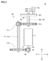
- FIG. 3 is a schematic front view for explaining the configuration and operation of the rotational motion transmission unit shown in FIG. 2
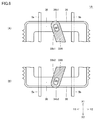
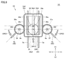
- FIG. 4 is a schematic top view for explaining the configuration and operation of the motion conversion unit shown in FIG. It is. 5 is a diagram showing an assembly structure on one end side of the pair of crank arms shown in FIG. 2
- FIG. 6 is a diagram showing an assembly structure on the other end side of the pair of crank arms shown in FIG. It is.
- a flapping apparatus 1 ⁇ / b> A includes a casing 100, a rotary motor 2 as a power source assembled to the casing 100, a power transmission mechanism 3 that transmits power generated by the rotary motor 2, It mainly includes a first wing body 4A and a second wing body 4B as a pair of wings driven by the transmission mechanism 3, and a battery (not shown) for supplying electric power to the rotary electric motor 2 described above.
- the power transmission mechanism 3 includes a rotary motion transmission unit 3A and a motion conversion unit 3B.
- the X-axis, Y-axis, and Z-axis are respectively taken on the front, rear, left, and right of the flapping device 1A, and the directions toward the front side and the rear side of the flapping device 1A are set.
- the X1 direction and the X2 direction are defined respectively, the directions toward the right side and the left side of the flapping device 1A are defined as the Y1 direction and the Y2 direction, respectively, and the flapping device 1A is directed toward the upper side and the lower side.
- the directions are defined as the Z1 direction and the Z2 direction, respectively, and the following description will be made using these axes and directions.
- the casing 100 is a member constituting the main body of the flapping apparatus 1A, and is formed by assembling the rotary motor 2, the power transmission mechanism 3, and the battery described above.
- the casing 100 is configured by, for example, a frame-shaped framework, and may be provided with a cover that covers the framework in addition to this.
- the rotary electric motor 2 is disposed at the lower part of the flapping apparatus 1A and is assembled to the housing 100 as described above.
- the rotary electric motor 2 includes an output shaft 2a that outputs a rotational motion, and the output shaft 2a is configured by a metal shaft.
- the output shaft 2a extends along the Z-axis direction, and a gear 2b is fixed to the tip of the output shaft 2a.
- the gear 2b rotates together with the output shaft 2a as the output shaft 2a rotates around the axis.
- the rotary motor 2 is controlled by a user or a control device to which a control instruction is given by an automated algorithm, but the details of the control are not directly related to the contents of the present invention, so the description is simplified. Therefore, the details are omitted here, and in the present embodiment, the description will be given on the assumption that the rotary motor 2 is directly driven by receiving the electric power from the battery (not shown). Further, the presence / absence of the control device and the specific control method in the case where the control device is provided do not have any influence when the present invention is applied.
- Rotational motion transmission unit 3A includes a first transmission member 31 and a second transmission member 32. Both the first transmission member 31 and the second transmission member 32 are rotatably supported by the housing 100.
- the first transmission member 31 is fixed to the first connection rod 31a extending along the Z-axis direction, the gear 31b fixed to one end of the first connection rod 31a, and the other end of the first connection rod 31a. And a gear 31c. Both the gear 31b and the gear 31c rotate around the axis of the first connecting rod 31a together with the first connecting rod 31a.
- the second transmission member 32 is fixed to the second connection rod 32a extending along the Z-axis direction, the gear 32b fixed to one end of the second connection rod 32a, and the other end of the second connection rod 32a. And a disk 32c as a rotation transmitting member. Both the gear 32b and the disk 32c rotate around the axis of the second connection rod 32a together with the second connection rod 32a.
- the gear 31b fixed to one end of the first connecting rod 31a meshes with the gear 2b fixed to the tip of the output shaft 2a. Further, the gear 32b fixed to one end of the second connection rod 32a meshes with the gear 31c fixed to the other end of the first connection rod 31a.
- the rotational motion generated in the output shaft 2a of the rotary electric motor 2 is transmitted to the first transmission member 31 and the second transmission member 32 as the rotational motion, and as a result, the output of the rotational motion transmission unit 3A.
- the disk 32c as a part rotates around the axis of the second connecting rod 32a. That is, the disk 32c as the rotation transmitting member rotates around the first rotation shaft 201 (see FIG. 4) extending in the direction parallel to the extending direction of the second connecting rod 32a (that is, the Z-axis direction).
- the first transmission member 31 and the second transmission member 32 function as a speed reducer by adjusting the number of teeth of the gears 31b, 31c, and 32b.
- first connection rod 31a of the first transmission member 31 and the second connection rod 32a of the second transmission member 32 are both constituted by carbon fiber rods.
- load fluctuation suppression portions A1 and A2 are configured by each of the first connecting rod 31a and the second connecting rod 32a, and details thereof will be described later. .
- the meshing portion of the gear 2b of the rotary motor 2 and the gear 31b of the first transmission member 31 and the meshing portion of the gear 31c of the first transmission member 31 and the gear 32b of the second transmission member 32 are respectively predetermined. Has a large backlash. Thereby, load fluctuation suppression units B1 and B2 (see FIG. 3), which will be described later, are configured by each of these meshing portions, and details thereof will be described later.
- the motion conversion unit 3 ⁇ / b> B is disposed above the rotary electric motor 2 and the rotary motion transmission unit 3 ⁇ / b> A, and includes the first crank arm 33 ⁇ / b> A, the second crank arm 33 ⁇ / b> B, and the crankpin.
- a crank including 34a, 34b1, and 34b2, a slider 35, an elastic belt 36, a first rotating body 37, and a second rotating body 38 are mainly provided.
- the slider 35 is configured by a rectangular frame-shaped member, and is located above the second transmission member 32 of the rotational motion transmission unit 3A.
- the slider 35 is movably supported by a pair of slide guides 5 a and 5 b provided on the housing 100. More specifically, the pair of slide guides 5a and 5b are arranged side by side in the Y-axis direction so as to extend along the X-axis direction, and the slide guide 5a, A plurality of through holes through which 5b is inserted are provided. As a result, the slide guides 5a and 5b are inserted through the plurality of through holes, so that the slider 35 is configured to be movable along the X-axis direction that is the first direction.
- a first crank arm 33A and a second crank arm 33B which are a pair of crank arms, are disposed below the slider 35 and above the second transmission member 32.
- the first crank arm 33A and the second crank arm 33B are both arranged so that their extending directions are parallel to the XY plane.
- first crank arm 33A is rotatably assembled to an eccentric position of disk 32c of second transmission member 32 by crank pin 34a, and the other end is slider by crank pin 34b1.
- 35 is rotatably assembled at the front end position.
- a hole 33a1 is provided at the one end of the first crank arm 33A, and the crank pin 34a is inserted into the disk 32c so as to be inserted through the hole 33a1.
- the hole 33a1 has a predetermined clearance for reducing friction so that the one end of the first crank arm 33A is rotatably assembled to the disk 32c. Is formed to be slightly larger than the crank pin 34a in the portion through which the shaft is inserted.
- the other end of the first crank arm 33A is provided with a hole 33b1, and the crank pin 34b1 is inserted into the hole 33b1 so that the front end of the slider 35 is inserted.
- the hole 33b1 is significantly larger than the outer shape of the crank pin 34b1 at a portion through which the hole 33b1 is inserted at least along the direction in which the first crank arm 33A extends (that is, a predetermined value for reducing friction).
- a predetermined value for reducing friction For example, a long hole as shown in the figure.
- the crank pin 34b1 is loosely fitted in the hole 33b1.
- the other end of the first crank arm 33A is not only rotatably attached to the slider 35, but is further attached so as to be slidable relative to the slider 35 in the XY plane direction.
- one end of the second crank arm 33B is rotatably assembled to the eccentric position of the disk 32c of the second transmission member 32 by a crank pin 34a, and the other end is a slider by the crank pin 34b2. 35 is rotatably assembled at the rear end position.
- a hole 33a2 is provided at the one end of the second crank arm 33B, and the crank pin 34a is inserted into the disk 32c so as to be inserted into the hole 33a2.
- the hole 33a2 has a predetermined clearance for reducing friction so that the one end of the second crank arm 33B is rotatably assembled to the disk 32c. Is formed to be slightly larger than the crank pin 34a in the portion through which the shaft is inserted.
- the other end of the second crank arm 33B is provided with a hole 33b2, and the crank pin 34b2 is inserted into the rear of the slider 35 so as to be inserted into the hole 33b2.
- the hole 33b2 is remarkably larger than the outer shape of the crank pin 34b2 in a portion through which the hole 33b2 is inserted at least along the direction in which the second crank arm 33B extends (that is, a predetermined value for reducing friction).
- a predetermined value for reducing friction For example, a long hole as shown in the figure.
- the crank pin 34b2 is loosely fitted in the hole 33b2.
- the other end of the second crank arm 33B is not only rotatably attached to the slider 35, but is also attached so as to be slidable relative to the slider 35 in the XY plane direction.
- the one end of the first crank arm 33A and the one end of the second crank arm 33B are rotatably assembled to the disk 32c by a common crank pin 34a. Therefore, one end of each of the first crank arm 33A and the second crank arm 33B rotates a common rotating shaft extending in a direction parallel to the extending direction of the first rotating shaft 201 of the disk 32c as the rotation transmitting member. As a center, it is rotatably connected to an eccentric position of the disk 32c.
- the other end of the first crank arm 33A and the other end of the second crank arm 33B are assembled to the slider 35 so as to be rotatable and slidable by different crank pins 34b1 and 34b2. It has been. Therefore, the other end of each of the first crank arm 33A and the second crank arm 33B extends in a direction parallel to the extending direction of the first rotating shaft 201 of the disk 32c as the rotation transmitting member, and the slider 35 moves.
- the rotation axis is different from each other and is connected to the slider so as to be rotatable about different rotation axes positioned at a distance in the X-axis direction, and the extending direction of the first rotation shaft 201 of the disk 32c as a rotation transmission member. In the orthogonal direction, the slider 35 is slidably connected.
- the disc 32c as the output portion of the rotary motion transmitting portion 3A rotates about the first rotation shaft 201, thereby the first crank arm 33A assembled to the disc 32c.
- the one end of the second crank arm 33B and the one end of the second crank arm 33B also rotate about the first rotation shaft 201.
- the slider 35 is periodically pushed and pulled by the first crank arm 33A and the second crank arm 33B, and reciprocating linearly along the X-axis direction that is the extending direction of the slide guides 5a and 5b. Will exercise.
- the movement range of the gravity center position of the slider 35 during the reciprocating linear movement of the slider 35 is indicated by an arrow AR1.
- a first rotating body 37 and a second rotating body 38 are disposed on the right and left sides of the slider 35, respectively. More specifically, the first rotating body 37 and the second rotating body 38 are arranged side by side in the Y-axis direction that is the third direction so as to sandwich the slider 35.
- the first rotator 37 and the second rotator 38 are each formed of a substantially cylindrical member, and are arranged so that the peripheral surfaces thereof face the slider 35.
- the first rotating body 37 is fixed to a guide shaft 6a provided in the housing 100 and extending in the Z-axis direction.
- the guide shaft 6a is rotatably supported by the housing 100. Yes.
- the first rotating body 37 can rotate around the second rotating shaft 202 extending in the Z-axis direction that is the second direction. Will be located.
- the second rotating body 38 is fixed to a guide shaft 6b provided in the housing 100 and extending in the Z-axis direction, and the guide shaft 6b is rotatably supported by the housing 100. As a result, as shown in FIG. 4, on the left side surface 35 b side of the slider 35, the second rotating body 38 can rotate around the third rotating shaft 203 extending in the Z-axis direction that is the second direction. Will be located.
- gear grooves are provided on the peripheral surfaces of the portions of the first rotating body 37 and the second rotating body 38 facing the slider 35 so as to circulate on the peripheral surfaces.
- the gear grooves are provided with teeth 37a and 38a, respectively, whereby the first rotating body 37 and the second rotating body 38 also function as gears.
- An elastic belt 36 is wound around the outer circumferential surface of the slider 35, the circumferential surface of the first rotating body 37, and the circumferential surface of the second rotating body 38.
- the elastic belt 36 includes a toothed belt provided with teeth 36a at a predetermined position on one main surface thereof.
- the elastic belt 36 may be made of any material as long as it exhibits elasticity, but is preferably made of resin or rubber.
- the elastic belt 36 needs to be designed based on the viewpoint of suppressing the fluctuation of the load described later.
- a portion of the elastic belt 36 wound around the outer circumferential surface of the slider 35 is fixed to the slider 35 in a portion of the outer circumferential surface of the slider 35 except for the right side surface 35a and the left side surface 35b described above. Further, in the portion of the elastic belt 36 that is wound around the outer peripheral surface of the slider 35, the above-described teeth 36a face outward.
- the portion wound around the outer peripheral surface of the slider 35 and the portion wound around the outer peripheral surface of the first rotating body 37 form the slider 35 and the first rotation so as to draw a figure eight. It is wound around the body 37.
- the above-described teeth 36 a face inward, and the gear provided on the circumferential surface of the first rotating body 37. It meshes with the teeth 37a of the groove.
- the portion wound around the outer peripheral surface of the slider 35 and the portion wound around the outer peripheral surface of the second rotating body 38 form the slider 35 and the second rotation so as to draw a figure eight. It is wound around the body 38.
- the above-described teeth 36 a face inward, and the gear provided on the circumferential surface of the second rotating body 38. It meshes with the tooth 38a of the groove.
- the non-fixed portion of the elastic belt 36 is wound around the first rotating body 37 on the right side surface 35 a side of the slider 35, and the non-fixed portion of the elastic belt 36 is wound on the left side surface 35 b side of the slider 35.
- the fixed portion is wound around the second rotating body 38.
- the elastic belt 36 of the portion wound around the first rotating body 37 and the second rotating body 38 with the reciprocating linear motion along the X-axis direction of the slider 35 described above causes the first rotating body 37 and the second rotating body 38 to be respectively. Accordingly, the first rotating body 37 and the second rotating body 38 are rotated around the second rotating shaft 202 and the third rotating shaft 203 described above, respectively. It will reciprocate in the direction of rotation.
- the rotating direction of the first rotating body 37 and the rotating direction of the second rotating body 38 are always opposite to each other.
- the rotary motion transmitted through the rotary motion transmission unit 3A is converted into a reciprocating motion, and the first rotary body 37 and the second rotary body 38 as output units of the motion conversion unit 3B.
- they will reciprocate synchronously in the direction of rotation.
- the first wing body 4A and the second wing body 4B are assembled to the first rotating body 37 and the second rotating body 38, respectively. More specifically, a base end that is one end of the mast 4a of the first wing body 4A is fixed to a predetermined position on the circumferential surface opposite to the side on which the slider 35 of the first rotating body 37 is located, A base end, which is one end of the mast 4b of the second wing body 4B, is fixed at a predetermined position on the peripheral surface opposite to the side where the slider 35 of the second rotating body 38 is located.
- the first wing body 4A is positioned in the Y1 direction so that the tip of the first wing body 4A is located on the starboard side of the flapping device 1A, and the tip is located on the opposite side to the side where the second rotator 38 is located when viewed from the first rotator 37.
- the second wing body 4B is located on the port side of the flapping device 1A on the side opposite to the side where the first rotator 37 is located when viewed from the second rotator 38. Thus, it extends toward the Y2 direction.
- the first rotating body 37 and the second rotating body 38 as the output unit of the motion converting unit 3 ⁇ / b> B are rotated in the rotation direction around the first rotating shaft 201 and the second rotating shaft 202, respectively.
- the first wing body 4A and the second wing body 4B are driven by the first rotator 37 and the second rotator 38, respectively, and swing synchronously.
- the first wing body 4A and the second wing body 4B also reciprocate synchronously in the rotation direction around the first rotation shaft 201 and the second rotation shaft 202, respectively.
- the wing body 4A and the second wing body 4B swing synchronously so that their tips move substantially along the X-axis direction, which is the first direction.
- the swing range of the first wing 4A and the second wing 4B is indicated by an arrow AR2.
- the rotary motion generated in the rotary motor 2 as the drive source is converted into the reciprocating motion when transmitted by the power transmission mechanism 3,
- the first wing 4A and the second wing 4B are configured to swing upon receiving the reciprocating motion.
- the first wing body 4A and the second wing body 4B are swung synchronously, so that the flapping device 1A flutters continuously, and a levitation force is obtained accordingly.
- the first wing body 4A and the first wing body 4A and the first wing body 4A and the second wing body 38 are reciprocated in the rotation direction during operation. Not only does the two wings 4B swing, but the slider 35 also performs a reciprocating linear motion. At that time, the reciprocating linear motion of the slider 35 and the swing of the first wing body 4A and the second wing body 4B are always in opposite directions.
- this point will be described in detail.
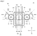
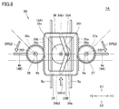
- FIGS. 7 to 10 are schematic top views for explaining the details of the operation of the motion conversion unit of the flapping apparatus in the present embodiment described above.
- FIGS. 7 to 10 show that the slider 35 and the first wing 4A and the second wing 4B perform the synchronous flapping operation of the first wing 4A and the second wing 4B from the state shown in FIG. It is the figure which showed how it moved in one period in time series.
- the slider 35 is at a substantially central position within the movable range of the reciprocating linear motion of the slider 35.
- the first wing 4A and the second wing 4B are at the 3 o'clock position and the 9 o'clock position, respectively, and when viewed from above in the Z2 direction, the first wing body 4A and the second wing body 4B The wings 4B are located on the same straight line.
- the one end of the first crank arm 33A and the one end of the second crank arm 33B that is, the pin 34a
- the disk 32c which is a connecting portion between the rotational motion transmitting portion 3A and the motion converting portion 3B. (The end on the side where is located) is at 9 o'clock.
- the disk 32c is rotated 90 ° counterclockwise from the state shown in FIG.
- the slider 35 moves in the DR11 direction shown in the figure, and accordingly, the center of gravity of the slider 35 also moves in the X2 direction.
- first wing body 4A and the second wing body 4B are directed toward the DR21 direction shown in the drawing by the first rotator 37 and the second rotator 38 rotating counterclockwise and clockwise, respectively. (That is, each toward the 12 o'clock position), this movement is generally in the X1 direction.
- the moving direction of the slider 35 and the moving directions of the first wing 4A and the second wing 4B are approximately opposite to each other along the X-axis direction. Therefore, when the gravity center position of the slider 35 moves backward in the X2 direction, the slider 35 acts as a counterweight, and the movement of the first wing 4A and the second wing 4B in the X1 direction is accompanied. The acceleration generated by the movement of the slider 35 and the acceleration generated by the movement of the slider 35 in the X2 direction are opposite to each other. As a result, the inertial force is canceled.
- first wing body 4A and the second wing body 4B are directed in the direction of DR22 shown in the figure by the clockwise rotation and counterclockwise rotation of the first rotating body 37 and the second rotating body 38, respectively. (That is, toward the 3 o'clock position and 9 o'clock position, respectively), this movement is generally in the X2 direction.
- the moving direction of the slider 35 and the moving directions of the first wing 4A and the second wing 4B are approximately opposite to each other along the X-axis direction. Therefore, the slider 35 acts as a counterweight when the position of the center of gravity of the slider 35 moves forward in the X1 direction, and as the first wing 4A and the second wing 4B move in the X2 direction. Thus, the acceleration caused by the movement of the slider 35 in the X1 direction is reversed, and as a result, the inertial force is canceled.
- first wing body 4A and the second wing body 4B are directed toward the DR23 direction shown in the drawing by the first rotator 37 and the second rotator 38 rotating clockwise and counterclockwise, respectively. (That is, toward the 6 o'clock position), this movement is generally in the X2 direction.
- the moving direction of the slider 35 and the moving directions of the first wing 4A and the second wing 4B are approximately opposite to each other along the X-axis direction. Therefore, the slider 35 acts as a counterweight when the position of the center of gravity of the slider 35 moves forward in the X1 direction, and as the first wing 4A and the second wing 4B move in the X2 direction. Thus, the acceleration caused by the movement of the slider 35 in the X1 direction is reversed, and as a result, the inertial force is canceled.
- the disk 32c is further rotated 90 ° counterclockwise from the state shown in FIG. 9 in response to the transmission of power from the rotary motor 2, so that the connecting portion is moved from the 12 o'clock position.
- the slider 35 moves in the DR14 direction shown in the figure, and accordingly, the center of gravity of the slider 35 also moves in the X2 direction.
- first wing body 4A and the second wing body 4B are directed toward the DR24 direction shown in the drawing by the first rotator 37 and the second rotator 38 rotating counterclockwise and clockwise, respectively. (I.e., toward the 3 o'clock position and 9 o'clock position, respectively), this movement is generally toward the X1 direction.
- the moving direction of the slider 35 and the moving directions of the first wing 4A and the second wing 4B are approximately opposite to each other along the X-axis direction. Therefore, when the gravity center position of the slider 35 moves backward in the X2 direction, the slider 35 acts as a counterweight, and the movement of the first wing 4A and the second wing 4B in the X1 direction is accompanied. The acceleration generated by the movement of the slider 35 and the acceleration generated by the movement of the slider 35 in the X2 direction are opposite to each other. As a result, the inertial force is canceled.
- the reciprocating linear motion of the slider 35 and the swing of the first wing body 4A and the second wing body 4B are always in opposite directions. Become.
- the slider 35 acts as a counterweight, the inertial force generated by the swinging of the first wing body 4A and the second wing body 4B is always canceled, and periodic vibration is generated in the casing 100. This is suppressed, and the posture of the flapping apparatus 1A is stabilized.
- the first body 4A and the second body 4B are smoothly swung, so that fluctuations in the load applied to the output shaft 2a of the rotary motor 2 as a power source are greatly suppressed. It will be possible.
- the slider 35 is configured to act as a counterweight as described above, the movement efficiency is greatly improved as compared with the conventional one, and a flapping apparatus having excellent flight capability can be obtained.
- the crank mechanism that connects the disk 32c as the rotation transmission member and the slider 35 is different from a crank mechanism that uses a single crank arm, It is constituted by a crank mechanism using a pair (that is, two) of crank arms (that is, the first crank arm 33A and the second crank arm 33B), and furthermore, ends of these pair of crank arms (that is, The other end of each of the first crank arm 33A and the second crank arm 33B is not only rotatably connected to the slider but also slidably connected to the slider 35.
- a crank mechanism using a pair (that is, two) of crank arms that is, the first crank arm 33A and the second crank arm 33B
- ends of these pair of crank arms that is, The other end of each of the first crank arm 33A and the second crank arm 33B is not only rotatably connected to the slider but also slidably connected to the slider 35.
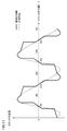
- FIG. 11 is a schematic graph comparing the slider speed change between the flapping apparatus in the present embodiment and the flapping apparatus according to the comparative embodiment.
- the horizontal axis of the graph shown in FIG. 11 represents the rotation angle of the crank, and the vertical axis represents the speed of the slider. Since both the first and second bodies are driven almost directly by the movement of the slider, the speed of the slider is considered to be the speed of the first and second bodies as it is. It's okay.
- the flapping apparatus according to the comparative embodiment differs from the flapping apparatus 1A according to the present embodiment in that it differs from the configuration of the crank mechanism that connects the disk and the slider, and the general one crank arm described above is used. These discs are connected to the slider.
- the second crank arm described above is not provided, and the disk and the slider are connected only by the first crank arm.
- one end of the first crank arm is assembled at an eccentric position of the disk so that it can only be rotated relative to the disk, and the other end of the first crank arm is attached to the slider.
- it is assembled at the front end position of the slider so that it can be assembled only in a rotatable manner (that is, it is not assembled so as to be slidable relative to the slider).
- the change in the moving speed of the slider when the slider is in the vicinity of the forefront position in the movable range is in the vicinity of the rearmost position in the movable range of the slider.
- the degree of the change is larger than the change in the moving speed of the slider. This is because the other end of one crank arm connecting the disk and the slider is connected to the front end position of the slider.
- the wings are turned back (that is, the wings are turned back at the front side of the swinging range of the wings (hereinafter referred to as “forward turning back”). )))) Is performed relatively smoothly according to the inertia due to the small speed change of the wings, but on the other hand, the wings are turned back by placing the slider near the foremost position (ie The reversing operation (hereinafter referred to as “rear reversing operation”) in which the wings are turned back at a position on the rear side of the swinging range of the wings is performed sufficiently smoothly due to the large speed change of the wings. In some cases, the backward turning operation becomes incomplete.
- the change in the moving speed of the slider 35 when the slider 35 is in the vicinity of the foremost position within the movable range, and the slider 35 is near the rearmost position within the movable range In each case, the change in the moving speed of the slider 35 is almost the same, and the degree of the change is sufficiently small.
- the other ends of the first crank arm 33A and the second crank arm 33B are not only rotatably connected to the slider 35 but also slidable relative to the slider 35.
- the slider 35 idles for a predetermined time at the timing when the slider 35 is positioned near the forefront position and the timing when the slider 35 is positioned near the rearmost position. This is because it is formed.
- the hole 33b1 provided at the other end of the first crank arm 33A and the hole 33b2 provided at the other end of the second crank arm 33B are both Since the corresponding crank pins 34b1 and 34b2 are larger than the size in the front-rear direction, the peripheral surface of the crank pin 34b1 that moves with the rotation of the disk 32c and the wall surface of the hole 33b1 at the two timings described above. And the contact between the peripheral surface of the crank pin 34b2 moving with the rotation of the disk 32c and the wall surface of the hole 33b2 are temporarily released. As a result, a state occurs in which the slider 35 is not temporarily driven by the first crank arm 33A and the second crank arm 33B.
- the state in which the slider 35 is idling is formed over the predetermined time at the predetermined timing described above, so that the moving speed of the slider 35 when the slider 35 is in the vicinity of the foremost position and the rearmost position within the movable range of the slider 35.
- both the forward turning operation and the backward turning operation are performed more smoothly and stably.
- the flapping apparatus 1A As described above, in the flapping apparatus 1A according to the present embodiment, it is possible to suppress the occurrence of the situation in which the wing body reversing operation as described above becomes incomplete, and the posture of the flapping apparatus is more stable. Thus, the effect of greatly improving the exercise efficiency as compared with the conventional case can be obtained.
- the state in which the slider 35 idles is formed over a predetermined time at a predetermined timing, thereby leading from the front turning operation to the rear turning operation.
- the movement of the wings toward the rear (hereinafter referred to as “back flapping action”) and the movement of the wings from the backward turning action to the forward turning action (hereinafter referred to as “forward flapping action”)
- forward flapping operation This is referred to as “forward flapping operation”
- the moving speed of the wings is also increased (that is, increased), so that a greater levitation force can be obtained. Therefore, also in this sense, the exercise efficiency is greatly improved, and a flapping apparatus having excellent flight performance can be obtained.
- flapping apparatus 1A there is almost no load applied to the drive source when the maximum load is generated in flapping apparatus according to the comparative embodiment (that is, when the first and second wings are turned back). Further, at the timing when the driving force from the driving source is transmitted to the slider 35, the reaction caused by the turning back operation of the first wing 4A and the second wing 4B does not hinder the rotation of the disk 32c. Therefore, by using the flapping apparatus 1A in the present embodiment, not only can the fluctuation of the load on the drive source be suppressed, but also the magnitude of the load applied to the drive source itself can be reduced, and the drive efficiency can be dramatically improved. The flapping apparatus can be improved.
- the movement of the slider 35 along the front-rear direction and the swing of the first wing body 4A and the second wing body 4B along the front-rear direction are reversed.
- the effect of the improvement of the exercise efficiency obtained by setting it as the said structure and the exercise efficiency obtained by providing a free running state over a predetermined time in a predetermined timing as mentioned above in a slider Therefore, it is not always necessary to configure the slider 35 so that the movement of the slider 35 and the swing of the first wing 4A and the second wing 4B are opposite to each other. It is not a requirement.
- An example is shown in which one end connected to the disc (that is, the end on the side where the crank pin 34a is located) is arranged at the 3 o'clock or 9 o'clock position with respect to the first rotating shaft 201 of the disk 32c. In this case, however, there is a strict difference between the swing range toward the front side and the swing range toward the rear side of the first wing body 4A and the second wing body 4B from the above state. Will occur.
- the one end of the first crank arm 33A and the one end of the second crank arm 33B are the first rotation shaft of the disk 32c.
- the first crank arm 33A and the second crank arm 33A are arranged on the front side with respect to 201 (that is, on the 2 o'clock side when viewed from the 3 o'clock position and on the 10 o'clock side when viewed from the 9 o'clock position).
- the length of the crank arm 33B may be adjusted appropriately.
- the power transmission mechanism 3 is provided with a plurality of load fluctuation suppression units A1, A2, B1, B2, C1, and C2.
- the load fluctuation suppression units A1, A2, B1, B2, C1, and C2 are all configured such that when the first body 4A and the second body 4B swing, the first body 4A and the second body 4B The fluctuation of the load that is generated by receiving the air resistance and is transmitted to the output shaft 2a of the rotary electric motor 2 through the power transmission mechanism 3 is suppressed.
- details of the load fluctuation suppression units A1, A2, B1, B2, C1, and C2 will be described.
- the load fluctuation suppressing portions A ⁇ b> 1 and A ⁇ b> 2 are configured by a first connection rod 31 a of the first transmission member 31 and a second connection rod 32 a of the second transmission member 32, respectively.
- the first connection rod 31 a and the second connection rod 32 a are both made of carbon fiber and are more easily twisted than the metal output shaft 2 a of the rotary electric motor 2.
- the first connecting rod 31a and the second connecting rod 32a are made of, for example, carbon fiber reinforced plastic (CFRP) having a fiber orientation in the axial direction of the rod, so that an appropriate elasticity against twisting is achieved. And a member having moderate rigidity against bending. Therefore, the first connecting rod 31a and the second connecting rod 32a can absorb the fluctuation of the load to a considerable extent by being twisted during the transmission of the load described above.
- CFRP carbon fiber reinforced plastic
- the first connecting rod 31a and the second connecting rod 32a are easily twisted, the first connecting rod 31a and the second connecting rod 32a are subjected to load fluctuations, so that a slight phase shift occurs in the transmission of the rotational motion. Will be generated. However, if this phase shift is sufficiently small, this does not give a large loss to the movement transmission, and conversely, the effect of absorbing the load fluctuation described above can be obtained remarkably.
- the first wing body 4A and the second wing body 4B are transmitted from the first wing body 4A and the second wing body 4B to the output shaft 2a of the rotary electric motor 2 through the power transmission mechanism 3 as the first wing body 4A and the second wing body 4B swing.
- Load fluctuations are leveled by being absorbed by the load fluctuation suppression units A1 and A2. Therefore, the fluctuation of the load applied to the output shaft 2a of the rotary electric motor 2 can be greatly suppressed.
- the load fluctuation suppressing portions B1 and B2 are respectively in meshing portions between the gear 2b of the rotary motor 2 and the gear 31b of the first transmission member 31 and the gear 31c of the first transmission member 31 and the first gear 31c. 2 It is comprised by the meshing part with the gear 32b of the transmission member 32.
- each of the meshing portions has a gap of a predetermined size, so-called backlash. That is, when these meshing portions have sufficient backlash, the load fluctuation can be absorbed to a considerable extent due to the presence of the backlash when the load is transmitted.
- the first wing body 4A and the second wing body 4B are transmitted from the first wing body 4A and the second wing body 4B to the output shaft 2a of the rotary electric motor 2 through the power transmission mechanism 3 as the first wing body 4A and the second wing body 4B swing.
- Load fluctuations are leveled by being absorbed by the load fluctuation suppression units B1 and B2. Therefore, the fluctuation of the load applied to the output shaft 2a of the rotary electric motor 2 can be greatly suppressed.
- the amount of backlash described above is preferably set as large as possible within a range in which the transmission of the rotational motion between the gears is not hindered.
- the load fluctuation suppressing portions C ⁇ b> 1 and C ⁇ b> 2 are each constituted by an elastic belt 36.
- the elastic belt 36 exhibits good elasticity. Therefore, when the load described above is transmitted from the first rotating body 37 and the second rotating body 38 to the slider 35, the elastic belt 36.
- this load fluctuation can be absorbed to a considerable extent.
- the first wing body 4A and the second wing body 4B are transmitted from the first wing body 4A and the second wing body 4B to the output shaft 2a of the rotary electric motor 2 through the power transmission mechanism 3 as the first wing body 4A and the second wing body 4B swing.
- Load fluctuations are leveled by being absorbed by the load fluctuation suppression units C1 and C2. Therefore, the fluctuation of the load applied to the output shaft 2a of the rotary electric motor 2 can be greatly suppressed.
- the first wing body 4A and the first wing body 4A and the first wing body 4A are separated by the load fluctuation suppression units A1, A2, B1, B2, C1, C2 provided in the power transmission mechanism 3. Since the fluctuation of the load that is transmitted from the two wings 4B to the output shaft 2a of the rotary electric motor 2 through the power transmission mechanism 3 can be greatly suppressed, the exercise efficiency is greatly improved as compared with the conventional case. Therefore, it is possible to provide a flapping apparatus having excellent flight capability.
- the first connection rod 31a and the second connection rod 32a made of a member that is more easily twisted than the metal output shaft 2a of the rotary electric motor 2 are used as the load fluctuation suppression portions A1 and A2.
- the first connection rod 31a and the second connection made of a member that is more flexible than the metal output shaft 2a of the rotary electric motor 2 are used as the load fluctuation suppression portions A1 and A2 instead. It is also possible to use the rod 32a.
- the first connecting rod 31a and the second connecting rod 32a are subjected to, for example, shape processing (for example, shape processing for making a cut on the surface of the metal rod) on a metal member that is difficult to deform. Therefore, the member can be made to have a moderate elasticity with respect to bending and a moderate rigidity with respect to torsion. For this reason, when the first connecting rod 31a and the second connecting rod 32a are formed of such members, the bending of the load when transmitting the load described above absorbs the load fluctuation to a considerable extent. can do.
- shape processing for example, shape processing for making a cut on the surface of the metal rod
- the first connecting rod 31a and the second connecting rod 32a when the first connecting rod 31a and the second connecting rod 32a are easily bent, the first connecting rod 31a and the second connecting rod 32a receive a change in load and cause a slight axial deviation. . However, if this axial deviation is sufficiently small, this does not give a large loss to the motion transmission, and conversely, the effect of absorbing the load fluctuation described above can be obtained remarkably.
- the first wing body 4A and the second wing body 4B are transmitted from the first wing body 4A and the second wing body 4B to the output shaft 2a of the rotary electric motor 2 through the power transmission mechanism 3 as the first wing body 4A and the second wing body 4B swing.
- Load fluctuations are leveled by being absorbed by the load fluctuation suppression units A1 and A2. Therefore, the fluctuation of the load applied to the output shaft 2a of the rotary electric motor 2 can be greatly suppressed.
- first connecting rod 31a and the second connecting rod 32a can be made of a member that is more easily twisted and bent than the metal output shaft 2a of the rotary electric motor 2.
- first connecting rod 31a and the second connecting rod 32a are made of resin, rubber, metal that is relatively easily deformed, or metal that is not easily deformed, or the like. What is necessary is just to comprise by what made this relatively easy to deform
- a plurality of load fluctuation suppression units A1, A2, B1, B2, C1, and C2 are provided, but at least one of them is provided in the power transmission mechanism 3. If so, the exercise efficiency can be improved considerably.
- only one of the first connecting rod 31a and the second connecting rod 32a may be made of carbon fiber reinforced plastic.
- FIG. 12 is a schematic top view showing the configuration of the motion conversion unit of the flapping apparatus according to Embodiment 2 of the present invention.
- the flapping apparatus 1B in the present embodiment will be described with reference to FIG.
- the operation of flapping apparatus 1B in the present embodiment is basically the same as the operation of flapping apparatus 1A in the above-described first embodiment, and therefore description thereof will not be repeated here.
- the flapping apparatus 1B in the present embodiment is between the slider 35, the first rotating body 37, and the second rotating body 38 when compared with the flapping apparatus 1A in the first embodiment described above. Is different in that the distance is configured to be larger.
- the distance between the slider 35 and the first rotating body 37 and the second rotating body 38 is adjusted so that the distance is larger than that of the flapping apparatus 1A. Has been. Accordingly, a gap G1 is formed between the elastic belt 36 and the right side surface 35a and the left side surface 35b of the slider 35.
- the elastic belt 36 is easily deformed and expanded as much as the gap G1 exists, and the expansion and contraction thereof. This deformation is not hindered by the slider 35, the first rotating body 37, and the second rotating body 38, so that the effect of absorbing the above-described load fluctuations can be obtained. Therefore, the exercise efficiency is further greatly improved, and a flapping apparatus having particularly excellent flight performance can be obtained.
- the size of the gap G1 between the slider 35 and the portion of the elastic belt 36 that meshes with the first rotating body 37 and the portion of the elastic belt 36 that meshes with the second rotating body 38 depends on the thickness of the elastic belt 36. It is preferable to be configured to be larger.
- FIG. 13 is a schematic top view which shows the structure of the motion conversion part of the flapping apparatus in Embodiment 3 of this invention.
- the flapping apparatus 1C according to the present embodiment will be described with reference to FIG.
- the flapping apparatus 1C in the present embodiment has the elastic belt 36 wound around the first rotating body 37 and the second rotating body 38 when compared with the flapping apparatus 1A in the first embodiment described above. Is different.
- this switching portion is opposite to the side on which the slider 35 is located when viewed from the first rotating body 37. It is configured to be arranged on the side (that is, the side on which the first wing body 4A is located).
- this switching portion is opposite to the side where the slider 35 is located when viewed from the second rotating body 38. It is configured to be arranged on the side (that is, the side on which the second wing 4B is located).
- a portion of the elastic belt 36 wound around the circumferential surface of the first rotating body 37 and a portion wound around the circumferential surface of the second rotating body 38 and the slider 35 are wound around the outer circumferential surface.
- the gap G2 is formed between the elastic belt 36 and the right side surface 35a and the left side surface 35b of the slider 35 as in the case of the second embodiment described above. Accordingly, the elastic belt 36 is easily deformed by expansion and contraction as much as the gap G2 exists, and the deformation such as expansion and contraction is not hindered by the slider 35, the first rotating body 37, and the second rotating body 38. Therefore, the effect that the above-described load fluctuation can be more remarkably absorbed is obtained.
- the movement of the slider 35 along the front-rear direction and the movement of the first wing body 4A and the second wing body 4B occurs almost always in the same direction, but the effect itself of improving the movement efficiency obtained by providing the slider 35 with a free running state at a predetermined timing for a predetermined time is itself. , You will definitely get. Therefore, the exercise efficiency is improved as compared with the conventional one, and a flapping device having particularly excellent flight performance can be obtained.
- the first wing body 4A, the second wing body 4B, and the slider 35 are separately provided in order to suppress the occurrence of periodic vibration in the casing 100. It is preferable to provide a balance mass serving as a counterweight with respect to the movement and its driving mechanism.
- FIG. 14 is a schematic top view showing the configuration of the motion conversion unit of the flapping apparatus according to Embodiment 4 of the present invention.
- flapping apparatus 1D in the present embodiment will be described.
- the operation of flapping apparatus 1D in the present embodiment is basically the same as the operation of flapping apparatus 1A in the above-described first embodiment, and therefore description thereof will not be repeated here.
- the flapping apparatus 1D in the present embodiment has a crank arm that connects the disk 32c as the rotation transmission member and the slider 35, as compared with the flapping apparatus 1A in the first embodiment described above. Further, it is different in that a pair (that is, two) is added.
- a disk 32c ′ that rotates together with the disk 32c is provided integrally with the disk 32c at a position above the disk 32c.
- the eccentric position of the disk 32c ′ and the slider 35 are provided.
- a third crank arm 33C and a fourth crank arm 33D are provided so as to connect the front end position and the rear end position.
- the assembly structure of the third crank arm 33C and the fourth crank arm 33D to the disk 32c ′ is the same as the assembly structure of the first crank arm 33A and the second crank arm 33B to the disk 32c.
- the assembly structure of the third crank arm 33C and the fourth crank arm 33D to the slider 35 is the same as the assembly structure of the first crank arm 33A and the second crank arm 33B to the slider 35, respectively.
- connection positions of the third crank arm 33C and the fourth crank arm 33D with respect to the disk 32c ′ are the first with respect to the first rotating shaft 201.
- the crank arm 33A and the second crank arm 33B are disposed at point symmetry positions with respect to the connection position of the disc 32c, and the connection positions of the third crank arm 33C and the fourth crank arm 33D to the slider 35 are respectively the first crank position.
- the arm 33 ⁇ / b> A and the second crank arm 33 ⁇ / b> B are disposed immediately above the connection position of the arm 33 ⁇ / b> A and the second crank arm 33 ⁇ / b> B with respect to the slider 35 (that is, the position above the slider 35).
- FIG. 15 is a schematic perspective view of a main part of the flapping apparatus according to Embodiment 5 of the present invention, in which a casing is not shown.
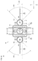
- FIG. 16 is a schematic top view for explaining the configuration and operation of the motion converter shown in FIG.
- flapping apparatus 1E according to the present embodiment will be described with reference to FIG. 15 and FIG.
- flapping apparatus 1E has a configuration of motion conversion unit 3B in power transmission mechanism 3 when compared with flapping apparatus 1A according to the first embodiment described above. Only the difference.
- the motion converter 3B includes a crank including a first crank arm 33A, a second crank arm 33B, and crank pins 34a, 34b1, and 34b2, a slider 35, a first rotating body 37, and a second rotating body. 38, and the elastic belt 36 as shown in the first embodiment is not provided.
- the slider 35 is constituted by a toothed slider, and more specifically, teeth 35c are provided on the right side surface 35a and the left side surface 35b of the slider 35, respectively.
- the first rotator 37 and the second rotator 38 are arranged so that their circumferential surfaces are in contact with the right side surface 35a and the left side surface 35b of the slider 35, respectively, whereby the right side surface 35a and the left side surface 35b of the slider 35 are arranged.
- the teeth 35c provided on the gears mesh with the gear groove teeth 37a provided on the peripheral surface of the first rotating body 37 and the gear groove teeth 38a provided on the peripheral surface of the second rotating body 38, respectively. .
- the flapping apparatus 1E in the present embodiment is configured such that the motion transmission between the slider 35 and the first rotating body 37 and the second rotating body 38 is configured by a so-called rack and pinion.
- the first and second rotating bodies 37 and 38 made of gears mesh with each other to realize motion transmission between them.
- the first rotating body 37 and the second rotating body 38 are moved to the first rotating shaft 201 and the second rotating body, respectively. It reciprocates in the rotation direction around the rotation shaft 202 as the rotation center. Note that the rotation direction of the first rotating body 37 and the rotating direction of the second rotating body 38 are always opposite to each other.
- the first rotating body 37 and the second rotating body 38 as the output unit of the motion converting unit 3B reciprocate synchronously in the rotation direction around the first rotating shaft 201 and the second rotating shaft 202, respectively.
- the first wing body 4A and the second wing body 4B are driven by the first rotator 37 and the second rotator 38, respectively, to swing synchronously.
- the reciprocating linear motion of the slider 35 and the swing of the first wing body 4A and the second wing body 4B are as follows. Since the direction is always reversed, the slider 35 acts as a counterweight, so that the inertia force generated by the swing of the first wing 4A and the second wing 4B is always canceled.
- first crank arm 33A and the second crank arm 33B are rotated with respect to the slider 35 as in the case of the first embodiment.
- the slider 35 is slidably connected to the slider 35, so that a state in which the slider 35 runs idle is formed over a predetermined time at a predetermined timing. Both the movement and the back turning action will be performed more smoothly and stably, and in addition, the movement speed of the wings will be greater (ie faster) in the rear flapping action and the forward flapping action, resulting in more It is possible to obtain a large levitation force.
- FIG. 17 is a schematic top view showing the configuration of the motion conversion unit of the flapping apparatus according to Embodiment 6 of the present invention.
- the flapping apparatus 1F in the present embodiment will be described with reference to FIG.
- the flapping apparatus 1F in the present embodiment is different in the configuration of the slider 35 when compared with the flapping apparatus 1E in the fifth embodiment described above.
- the flapping apparatus 1E is configured such that the first rotating body 37 and the second rotating body 38 are disposed outside the right side and the left side of the slider 35 made of a rectangular frame-shaped member, respectively.
- the size of the slider 35 made of a rectangular frame-shaped member is adjusted, so that the first inner side of the slider 35 and the inner side of the left side respectively.
- the first rotator 37 and the second rotator 38 are arranged.
- teeth 35c are provided on the inner peripheral surface of the right side and the inner peripheral surface of the left side of the slider 35, respectively, and these teeth 35c are gear grooves provided on the peripheral surface of the first rotating body 37, respectively.
- Teeth 37a and gear groove teeth 38a provided on the peripheral surface of the second rotating body 38.
- the movement of the slider 35 along the front-rear direction and the front-rear direction of the first body 4A and the second body 4B is certainly reliable. Will be obtained. Therefore, the exercise efficiency is improved as compared with the conventional one, and a flapping device having particularly excellent flight performance can be obtained.
- the first wing body 4A, the second wing body 4B, and the slider 35 are separately provided in order to suppress the occurrence of periodic vibration in the casing 100. It is preferable to provide a balance mass serving as a counterweight with respect to the movement and its driving mechanism.
- the power generated by a single power source is distributed by the power transmission mechanism, so that the wings provided on the starboard of the chassis and the port on the chassis are provided.
- the wings provided on the starboard side of the casing and the wings provided on the port side of the casing are separately provided.
- it may be configured to be driven by a drive source provided.
- annular (that is, endless) elastic belt made of a single member is wound around the slider, the first rotating body, and the second rotating body.
- this may be replaced by a non-circular elastic belt having an end, or the elastic belt wound only on the slider and the first rotating body, the slider and the first This may be replaced by an elastic belt wound only on two rotating bodies.
- the first rotating body and the second rotating body are configured by gears
- the elastic belt is configured by a toothed belt.
- it is good also as comprising a 1st rotary body and a 2nd rotary body with the friction roller which does not have a tooth
- the first rotating body and the second rotating body are configured by gears, and the slider is configured by a toothed slider.
- the first rotating body and the second rotating body may be configured by a friction roller having no teeth, and the slider may be configured by a friction slider having no teeth.
- 1A to 1F flapping device 2 rotary motor, 2a output shaft, 2b gear, 3 power transmission mechanism, 3A rotary motion transmission unit, 3B motion conversion unit, 31 first transmission member, 31a first connection rod, 31b, 31c gear, 32 2nd transmission member, 32a 2nd connecting rod, 32b gear, 32c, 32c 'disk, 33A 1st crank arm, 33B 2nd crank arm, 33C 3rd crank arm, 33D 4th crank arm, 33a1, 33a2, 33b1 , 33b2 hole, 34a, 34b1, 34b2 crank pin, 35 slider, 35a right side, 35b left side, 35c tooth, 36 elastic belt, 36a tooth, 37 first rotating body, 37a tooth, 38 second rotating body, 38a Teeth, 4A 1st body, 4B 2nd body 4a, 4b mast, 5a, 5b slide guide, 6a, 6b guide shaft, 100 housing, 201 first rotating shaft, 202 second rotating shaft, 203 third rotating shaft, A1, A2, B1, B2, C1,
Landscapes
- Engineering & Computer Science (AREA)
- Aviation & Aerospace Engineering (AREA)
- Chemical & Material Sciences (AREA)
- Combustion & Propulsion (AREA)
- General Engineering & Computer Science (AREA)
- Mechanical Engineering (AREA)
- Remote Sensing (AREA)
- Toys (AREA)
- Transmission Devices (AREA)
Abstract
羽ばたき装置(1A)は、動力源と、動力伝達機構と、動力伝達機構によって駆動される羽体(4A,4B)とを備える。動力伝達機構は、動力源からの動力の伝達を受けて回転する回転伝達部材(32c)と、回転伝達部材(32c)からの動力の伝達を受けてX軸方向に往復直線運動するスライダ(35)と、スライダ(35)からの動力の伝達を受けて回転方向に往復運動する回転体(37,38)とを含む。羽体(4A,4B)は、回転体(37,38)が回転方向に往復運動することでその先端が概ねX軸方向に沿って移動するように揺動する。動力伝達機構は、回転伝達部材(32c)とスライダ(35)とを接続する一対のクランクアーム(33A,33B)をさらに含み、これらの各々の一端は、回転伝達部材(32c)に対して回転可能に接続され、これらの各々の他端は、スライダ(35)に対して回転かつスライド移動可能に接続される。
Description
本発明は、躯体に組付けられた動力源によって羽体が駆動されて揺動することで浮上力を得る羽ばたき装置に関する。
通常、羽ばたき装置においては、躯体の左舷および右舷のそれぞれに羽体が設けられており、躯体に組付けられた動力源によって当該羽体が駆動される。その際、羽体は、躯体側に位置する基端を回転中心として当該基端とは反対側に位置する先端が概ね前後方向に向けて移動するように揺動する。
たとえば、特表2012-529398号公報(特許文献1)の図9には、羽体が取付けられたマストの基端にロッカーアームが組付けられ、駆動源としての回転電動機から出力される回転運動がクランクによって往復直線運動に変換されることでロッカーアームが周期的に押し引きされ、これによりロッカーアームによってマストが駆動されることで羽体が前後方向に揺動するように構成された羽ばたき装置が開示されている。
ここで、羽体が前後方向に揺動するように構成された羽ばたき装置においては、羽体の移動速度が可能な限り速められていることが必要であるとともに、羽体の切り返し動作が確実に履行されるように構成されていることが重要である。羽体の移動速度が遅い場合には、羽ばたき装置の浮上力が低下してしまうことになり、また羽体の切り返しが不完全である場合には、羽ばたき装置の姿勢が安定しないことになり、いずれの場合にも運動効率が低下することとなって飛行能力が大幅に劣ったものとなってしまう。
したがって、本発明は、上記の問題に鑑みてなされたものであり、運動効率の向上が図られた羽ばたき装置を提供することを目的とする。
本発明の第1の局面に基づく羽ばたき装置は、躯体と、上記躯体に組付けられた動力源と、羽体と、上記動力源にて発生した動力を上記羽体に伝達する動力伝達機構と、を備えている。上記羽体は、上記動力伝達機構によって駆動される。上記動力伝達機構は、上記躯体によって回転可能に支持され、上記動力源からの動力の伝達を受けて第1回転軸を回転中心として回転する回転伝達部材と、上記躯体によって移動可能に支持され、上記回転伝達部材からの動力の伝達を受けて第1方向に往復直線運動するスライダと、上記躯体によって回転可能に支持され、上記スライダからの動力の伝達を受けて上記第1方向と直交する第2方向に延在する第2回転軸を回転中心として回転方向に往復運動する回転体と、を含んでいる。上記羽体は、その基端が上記回転体に固定されることにより、上記回転体が上記回転方向に往復運動することでその先端が概ね上記第1方向に沿って移動するように揺動する。上記動力伝達機構は、上記回転伝達部材と上記スライダとを接続する一対のクランクアームをさらに含んでいる。上記一対のクランクアームの各々の一端は、上記第1回転軸の延在方向と平行な方向に延在する共通の回転軸を回転中心として、上記回転伝達部材の偏心位置に回転可能に接続されている。上記一対のクランクアームの各々の他端は、上記第1回転軸の延在方向と平行な方向に延在しかつ上記第1方向において距離をもって位置する互いに異なる回転軸を回転中心として、上記スライダに対して回転可能に接続されている。さらに、上記一対のクランクアームの各々の上記他端は、上記第1回転軸の延在方向と直交する方向において、上記スライダに対してスライド移動可能に接続されている。
上記本発明の第1の局面に基づく羽ばたき装置にあっては、上記一対のクランクアームの各々の上記他端に孔部が設けられるとともに、上記孔部に挿通するようにクランクピンが上記スライダに取付けられることにより、上記一対のクランクアームの各々の上記他端が、上記スライダに対して回転可能に接続されていることが好ましく、またその場合に、上記孔部に上記クランクピンが遊嵌されることにより、上記一対のクランクアームの各々の上記他端が、上記第1回転軸の延在方向と直交する方向において、上記スライダに対してスライド移動可能に接続されていることが好ましい。
上記本発明の第1の局面に基づく羽ばたき装置の第1の態様にあっては、上記動力伝達機構が、上記スライダに一部が固定された弾性ベルトをさらに含んでいてもよく、その場合には、上記スライダに対する上記弾性ベルトの非固定部分が上記回転体に巻回されることにより、上記スライダが往復直線運動することで上記回転体が上記回転方向に往復運動することになる。
上記第1の態様にあっては、上記回転体が、ギヤからなるとともに、上記弾性ベルトが、上記ギヤに歯合する歯付きベルトからなることが好ましい。
上記本発明の第1の局面に基づく羽ばたき装置の第2の態様にあっては、上記スライダと上記回転体とが接触していてもよく、その場合には、上記スライダが往復直線運動することで上記回転体が上記回転方向に往復運動することになる。
上記第2の態様にあっては、上記回転体が、ギヤからなるとともに、上記スライダが、上記ギヤに歯合する歯付きスライダからなることが好ましい。
上記本発明の第1の局面に基づく羽ばたき装置にあっては、上記スライダの上記第1方向に沿った移動と、上記羽体の上記第1方向に沿った揺動とが、逆向きであることが好ましい。
本発明の第2の局面に基づく羽ばたき装置は、躯体と、上記躯体に組付けられた動力源と、第1羽体および第2羽体と、上記動力源にて発生した動力を上記第1羽体および上記第2羽体に伝達する動力伝達機構と、を備えている。上記第1羽体および上記第2羽体は、上記動力伝達機構によって駆動される。上記動力伝達機構は、上記躯体によって回転可能に支持され、上記動力源からの動力の伝達を受けて第1回転軸を回転中心として回転する回転伝達部材と、上記躯体によって移動可能に支持され、上記回転伝達部材からの動力の伝達を受けて第1方向に往復直線運動するスライダと、上記躯体によって回転可能に支持され、上記スライダからの動力の伝達を受けて上記第1方向と直交する第2方向に延在する第2回転軸および第3回転軸をそれぞれ回転中心として回転方向に往復運動する第1回転体および第2回転体と、を含んでいる。上記第1回転体および上記第2回転体は、上記第1方向および上記第2方向の双方に直交する第3方向に沿って並んで配置されている。上記第1羽体は、その先端が上記第1回転体から見て上記第2回転体が位置する側とは反対側に位置するようにその基端が上記第1回転体に固定されており、上記第2羽体は、その先端が上記第2回転体から見て上記第1回転体が位置する側とは反対側に位置するようにその基端が上記第2回転体に固定されている。上記第1羽体および上記第2羽体は、上記第1回転体および上記第2回転体がそれぞれ回転方向に往復運動することで各々の先端が同期的に概ね上記第1方向に沿って移動するように揺動する。上記動力伝達機構は、上記回転伝達部材と上記スライダとを接続する一対のクランクアームをさらに含んでいる。上記一対のクランクアームの各々の一端は、上記第1回転軸の延在方向と平行な方向に延在する共通の回転軸を回転中心として、上記回転伝達部材の偏心位置に回転可能に接続されている。上記一対のクランクアームの各々の他端は、上記第1回転軸の延在方向と平行な方向に延在しかつ上記第1方向において距離をもって位置する互いに異なる回転軸を回転中心として、上記スライダに対して回転可能に接続されている。さらに、上記一対のクランクアームの各々の上記他端は、上記第1回転軸の延在方向と直交する方向において、上記スライダに対してスライド移動可能に接続されている。
上記本発明の第2の局面に基づく羽ばたき装置にあっては、上記スライダの上記第1方向に沿った移動と、上記第1羽体および上記第2羽体の上記第1方向に沿った揺動とが、逆向きであることが好ましい。
本発明によれば、運動効率の向上が図られた羽ばたき装置を提供することが可能になる。
以下、本発明の実施の形態について、図を参照して詳細に説明する。なお、以下に示す実施の形態においては、同一のまたは共通する部分について図中同一の符号を付し、その説明は繰り返さない。
(実施の形態1)
図1は、本発明の実施の形態1における羽ばたき装置の要部の概略斜視図であり、図2は、躯体の図示を省略した当該要部の概略斜視図である。図3は、図2に示す回転運動伝達部の構成および動作を説明するための概略正面図であり、図4は、図2に示す運動変換部の構成および動作を説明するための概略上面図である。また、図5は、図2に示す一対のクランクアームの一端側の組付構造を示す図であり、図6は、図2に示す一対のクランクアームの他端側の組付構造を示す図である。まず、これら図1ないし図6を参照して、本実施の形態における羽ばたき装置1Aの構成および概略的な動作について説明する。
図1は、本発明の実施の形態1における羽ばたき装置の要部の概略斜視図であり、図2は、躯体の図示を省略した当該要部の概略斜視図である。図3は、図2に示す回転運動伝達部の構成および動作を説明するための概略正面図であり、図4は、図2に示す運動変換部の構成および動作を説明するための概略上面図である。また、図5は、図2に示す一対のクランクアームの一端側の組付構造を示す図であり、図6は、図2に示す一対のクランクアームの他端側の組付構造を示す図である。まず、これら図1ないし図6を参照して、本実施の形態における羽ばたき装置1Aの構成および概略的な動作について説明する。
図1に示すように、羽ばたき装置1Aは、躯体100と、躯体100に組付けられた動力源としての回転電動機2と、回転電動機2にて発生した動力を伝達する動力伝達機構3と、動力伝達機構3によって駆動される一対の羽体としての第1羽体4Aおよび第2羽体4Bと、上述した回転電動機2に電力を供給する図示しないバッテリとを主として備えている。図2に示すように、動力伝達機構3は、回転運動伝達部3Aと運動変換部3Bとを含んでいる。
ここで、図1および図2に示すように、羽ばたき装置1Aの前後、左右および上下にそれぞれX軸、Y軸およびZ軸をとり、羽ばたき装置1Aの前方側および後方側に向けての方向をそれぞれX1方向およびX2方向と定義し、羽ばたき装置1Aの右方側および左方側に向けての方向をそれぞれY1方向およびY2方向と定義し、羽ばたき装置1Aの上方側および下方側に向けての方向をそれぞれZ1方向およびZ2方向と定義し、以下においては、これら軸および方向を用いて説明を行なう。
図1に示すように、躯体100は、羽ばたき装置1Aの本体部を構成する部材であり、上述した回転電動機2、動力伝達機構3およびバッテリが組付けられてなるものである。躯体100は、たとえばフレーム状の骨組みにて構成されており、これに加えて当該骨組みを覆うカバーを備えていてもよい。
図1ないし図3に示すように、回転電動機2は、羽ばたき装置1Aの下部に配置されており、上述したように躯体100に組付けられている。回転電動機2は、回転運動を出力する出力シャフト2aを含んでおり、出力シャフト2aは、金属製のシャフトにて構成されている。出力シャフト2aは、Z軸方向に沿って延在して配置されており、その先端にギヤ2bが固定されている。ギヤ2bは、出力シャフト2aの軸線周りの回転に伴って出力シャフト2aと共に回転する。
なお、通常、回転電動機2は、使用者もしくは自動化されたアルゴリズムにより制御指示が与えられる制御装置によって制御されるが、当該制御の詳細は、本発明の内容に直接関係しないため、説明の簡略化のためにここではその詳細を省略し、本実施の形態においては、上述した図示しないバッテリからの電力を受けて回転電動機2が直接的に駆動されるものとして、その説明を行なう。また、上述した制御装置の有無や制御装置を備える場合における具体的な制御方法は、本発明を適用する際に何ら影響を及ぼすものではない。
回転運動伝達部3Aは、第1伝達部材31と第2伝達部材32とを含んでいる。第1伝達部材31および第2伝達部材32は、いずれも躯体100によって回転可能に支持されている。
第1伝達部材31は、Z軸方向に沿って延在する第1接続ロッド31aと、第1接続ロッド31aの一端に固定されたギヤ31bと、第1接続ロッド31aの他端に固定されたギヤ31cとを有している。ギヤ31bおよびギヤ31cは、いずれも第1接続ロッド31aと共に第1接続ロッド31aの軸線周りに回転する。
第2伝達部材32は、Z軸方向に沿って延在する第2接続ロッド32aと、第2接続ロッド32aの一端に固定されたギヤ32bと、第2接続ロッド32aの他端に固定された回転伝達部材としてのディスク32cとを有している。ギヤ32bおよびディスク32cは、いずれも第2接続ロッド32aと共に第2接続ロッド32aの軸線周りに回転する。
第1接続ロッド31aの一端に固定されたギヤ31bは、出力シャフト2aの先端に固定されたギヤ2bと歯合している。また、第2接続ロッド32aの一端に固定されたギヤ32bは、第1接続ロッド31aの他端に固定されたギヤ31cと歯合している。
以上により、回転電動機2の出力シャフト2aに生じた回転運動が、第1伝達部材31および第2伝達部材32へ回転運動のまま伝達されることになり、その結果、回転運動伝達部3Aの出力部としてのディスク32cが第2接続ロッド32aの軸線周りに回転運動することになる。すなわち、回転伝達部材としてのディスク32cは、第2接続ロッド32aの延在方向と平行な方向(すなわちZ軸方向)に延在する第1回転軸201(図4参照)を回転中心として回転する。なお、第1伝達部材31および第2伝達部材32は、ギヤ31b,31c,32bの歯数が調節されることにより、減速機として機能する。
ここで、第1伝達部材31の第1接続ロッド31aおよび第2伝達部材32の第2接続ロッド32aは、いずれも炭素繊維製のロッドにて構成されている。これにより、これら第1接続ロッド31aおよび第2接続ロッド32aの各々によって後述する負荷変動抑制部A1,A2(図3参照)が構成されることになるが、その詳細については後述することとする。
また、回転電動機2のギヤ2bと第1伝達部材31のギヤ31bとの歯合部および第1伝達部材31のギヤ31cと第2伝達部材32のギヤ32bとの歯合部は、それぞれ所定の大きさのバックラッシュを有している。これにより、これら歯合部の各々によって後述する負荷変動抑制部B1,B2(図3参照)が構成されることになるが、その詳細については後述することとする。
図1、図2および図4に示すように、運動変換部3Bは、回転電動機2および回転運動伝達部3Aの上方に配置されており、第1クランクアーム33Aおよび第2クランクアーム33Bならびにクランクピン34a,34b1,34b2からなるクランクと、スライダ35と、弾性ベルト36と、第1回転体37と、第2回転体38とを主として備えている。
スライダ35は、矩形枠状の部材にて構成されており、回転運動伝達部3Aの第2伝達部材32の上方に位置している。スライダ35は、躯体100に設けられた一対のスライドガイド5a,5bによって移動可能に支持されている。より詳細には、一対のスライドガイド5a,5bは、X軸方向に沿って延在するようにY軸方向に並んで配設されており、スライダ35の所定位置には、当該スライドガイド5a,5bが挿通される複数の貫通孔が設けられている。これにより、当該複数の貫通孔にスライドガイド5a,5bが挿通されることにより、スライダ35は、第1方向であるX軸方向に沿って移動可能に構成されている。
スライダ35の下方であって第2伝達部材32の上方には、一対のクランクアームである第1クランクアーム33Aおよび第2クランクアーム33Bが配置されている。第1クランクアーム33Aおよび第2クランクアーム33Bは、いずれもその延在方向がXY平面と平行となるように配置されている。
図4を参照して、第1クランクアーム33Aは、その一端がクランクピン34aによって第2伝達部材32のディスク32cの偏心位置に回転可能に組付けられており、その他端がクランクピン34b1によってスライダ35の前端位置に回転可能に組付けられている。
より詳細には、図5(A)に示すように、第1クランクアーム33Aの上記一端には、孔部33a1が設けられており、当該孔部33a1に挿通するようにクランクピン34aがディスク32cに取付けられている。ここで、第1クランクアーム33Aの上記一端がディスク32cに対して回転可能に組付けられることとなるように、孔部33a1は、摩擦を低減するための所定のクリアランス分だけ、当該孔部33a1を挿通する部分のクランクピン34aよりも僅かに大きく形成されている。
一方、図6(A)に示すように、第1クランクアーム33Aの上記他端には、孔部33b1が設けられており、当該孔部33b1に挿通するようにクランクピン34b1がスライダ35の前端位置に取付けられている。ここで、孔部33b1は、少なくとも第1クランクアーム33Aが延びる方向に沿って、当該孔部33b1を挿通する部分のクランクピン34b1の外形よりも顕著に大きく(すなわち、摩擦を低減するための所定のクリアランス分よりも十分に大きく)形成されており、たとえば図示する如くの長孔によって構成されている。これにより、クランクピン34b1は、孔部33b1に遊嵌されている。
そのため、第1クランクアーム33Aの上記他端は、スライダ35に回転可能に組付けられるばかりでなく、さらに、XY平面内方向において、スライダ35に対してスライド移動可能に組付けられることになる。
図4を参照して、第2クランクアーム33Bは、その一端がクランクピン34aによって第2伝達部材32のディスク32cの偏心位置に回転可能に組付けられており、その他端がクランクピン34b2によってスライダ35の後端位置に回転可能に組付けられている。
より詳細には、図5(B)に示すように、第2クランクアーム33Bの上記一端には、孔部33a2が設けられており、当該孔部33a2に挿通するようにクランクピン34aがディスク32cに取付けられている。ここで、第2クランクアーム33Bの上記一端がディスク32cに対して回転可能に組付けられることとなるように、孔部33a2は、摩擦を低減するための所定のクリアランス分だけ、当該孔部33a2を挿通する部分のクランクピン34aよりも僅かに大きく形成されている。
一方、図6(B)に示すように、第2クランクアーム33Bの上記他端には、孔部33b2が設けられており、当該孔部33b2に挿通するようにクランクピン34b2がスライダ35の後端位置に取付けられている。ここで、孔部33b2は、少なくとも第2クランクアーム33Bが延びる方向に沿って、当該孔部33b2を挿通する部分のクランクピン34b2の外形よりも顕著に大きく(すなわち、摩擦を低減するための所定のクリアランス分よりも十分に大きく)形成されており、たとえば図示する如くの長孔によって構成されている。これにより、クランクピン34b2は、孔部33b2に遊嵌されている。
そのため、第2クランクアーム33Bの上記他端は、スライダ35に回転可能に組付けられるばかりでなく、さらに、XY平面内方向において、スライダ35に対してスライド移動可能に組付けられることになる。
ここで、上記のように、第1クランクアーム33Aの上記一端と第2クランクアーム33Bの上記一端とは、共通のクランクピン34aによってディスク32cに回転可能に組付けられている。そのため、第1クランクアーム33Aおよび第2クランクアーム33Bの各々の一端は、回転伝達部材としてのディスク32cの第1回転軸201の延在方向と平行な方向に延在する共通の回転軸を回転中心として、当該ディスク32cの偏心位置に回転可能に接続されることになる。
一方、上記のように、第1クランクアーム33Aの上記他端と第2クランクアーム33Bの上記他端とは、それぞれ互いに異なるクランクピン34b1,34b2によってスライダ35に回転可能かつスライド移動可能に組付けられている。そのため、第1クランクアーム33Aおよび第2クランクアーム33Bの各々の他端は、回転伝達部材としてのディスク32cの第1回転軸201の延在方向と平行な方向に延在しかつスライダ35の移動方向であるX軸方向において距離をもって位置する互いに異なる回転軸を回転中心として、スライダに対して回転可能に接続されるとともに、回転伝達部材としてのディスク32cの第1回転軸201の延在方向と直交する方向において、スライダ35に対してスライド移動可能に接続されることになる。
これにより、図4に示すように、回転運動伝達部3Aの出力部としてのディスク32cが第1回転軸201を回転中心として回転運動することにより、ディスク32cに組付けられた第1クランクアーム33Aの上記一端および第2クランクアーム33Bの上記一端(すなわち、クランクピン34aが位置する側の端部)も第1回転軸201を回転中心として回転することになる。これに伴い、スライダ35は、第1クランクアーム33Aおよび第2クランクアーム33Bによって周期的に押し引きされることになり、スライドガイド5a,5bの延在方向であるX軸方向に沿って往復直線運動することになる。なお、図4においては、当該スライダ35の往復直線運動の際のスライダ35の重心位置の移動範囲を矢印AR1にて表わしている。
図2および図4に示すように、スライダ35の右方および左方には、それぞれ第1回転体37および第2回転体38が配置されている。より詳細には、第1回転体37および第2回転体38は、スライダ35を挟むように第3方向であるY軸方向において並んで配置されている。第1回転体37および第2回転体38は、それぞれ略円柱状の部材にて構成されており、その周面がスライダ35に対向するように配置されている。
より具体的には、第1回転体37は、躯体100に設けられたZ軸方向に延在するガイドシャフト6aに固定されており、当該ガイドシャフト6aは、躯体100によって回転可能に支持されている。これにより、図4に示すように、スライダ35の右側面35a側において、第1回転体37が、第2方向であるZ軸方向に延在する第2回転軸202を回転中心として回転可能に位置することになる。
また、第2回転体38は、躯体100に設けられたZ軸方向に延在するガイドシャフト6bに固定されており、当該ガイドシャフト6bは、躯体100によって回転可能に支持されている。これにより、図4に示すように、スライダ35の左側面35b側において、第2回転体38が、第2方向であるZ軸方向に延在する第3回転軸203を回転中心として回転可能に位置することになる。
なお、第1回転体37および第2回転体38のスライダ35と対面する部分の周面には、それぞれ当該周面上を周回するようにギヤ溝が設けられている。当該ギヤ溝には、それぞれ歯37a,38aが設けられており、これにより第1回転体37および第2回転体38が、ギヤとしても機能することになる。
スライダ35の外周面と、第1回転体37の周面および第2回転体38の周面には、弾性ベルト36が巻回されている。当該弾性ベルト36は、その一方の主面の所定位置に歯36aが設けられた歯付きベルトからなる。弾性ベルト36は、弾性を呈する限りにおいてはどのような材質のものであっても構わないが、樹脂製またはゴム製であることが好ましい。なお、弾性ベルト36は、後述する負荷の変動を抑制する観点に基づいてその設計を行なうことが必要である。
弾性ベルト36のうち、スライダ35の外周面に巻回された部分は、スライダ35の外周面のうちの上述した右側面35aおよび左側面35bを除く部分においてスライダ35に固定されている。また、弾性ベルト36のうち、スライダ35の外周面に巻回された部分においては、上述した歯36aが外側を向いている。
また、弾性ベルト36のうち、スライダ35の外周面に巻回された部分と第1回転体37の周面に巻回された部分とは、8の字を描くようにスライダ35および第1回転体37に巻き付けられている。ここで、弾性ベルト36のうち、第1回転体37の周面に巻回された部分においては、上述した歯36aが内側を向いており、第1回転体37の周面に設けられたギヤ溝の歯37aに歯合している。
さらに、弾性ベルト36のうち、スライダ35の外周面に巻回された部分と第2回転体38の周面に巻回された部分とは、8の字を描くようにスライダ35および第2回転体38に巻き付けられている。ここで、弾性ベルト36のうち、第2回転体38の周面に巻回された部分においては、上述した歯36aが内側を向いており、第2回転体38の周面に設けられたギヤ溝の歯38aに歯合している。
これにより、スライダ35の右側面35a側においては、弾性ベルト36の非固定部分が第1回転体37に巻回されることになり、スライダ35の左側面35b側においては、弾性ベルト36の非固定部分が第2回転体38に巻回されることになる。
そのため、上述したスライダ35のX軸方向に沿った往復直線運動に伴い、第1回転体37および第2回転体38に巻回された部分の弾性ベルト36がそれぞれ第1回転体37および第2回転体38の回転方向に沿って送られることになり、これに伴って第1回転体37および第2回転体38が、それぞれ上述した第2回転軸202および第3回転軸203を回転中心として回転方向に往復運動することになる。ここで、第1回転体37の回転方向と第2回転体38の回転方向とは、常時逆向きとなる。
以上により、運動変換部3Bにおいては、回転運動伝達部3Aを介して伝達された回転運動が往復運動に変換され、運動変換部3Bの出力部としての第1回転体37および第2回転体38が、それぞれ回転方向に同期的に往復運動することになる。
ここで、上述したように、スライダ35と第1回転体37および第2回転体38との間の運動伝達は、弾性ベルト36によって実現されている。これにより、この弾性ベルト36によって後述する負荷変動抑制部C1,C2(図4参照)が構成されることになるが、その詳細については後述することとする。
図2および図4に示すように、第1羽体4Aおよび第2羽体4Bは、それぞれ第1回転体37および第2回転体38に組付けられている。より詳細には、第1回転体37のスライダ35が位置する側とは反対側の周面の所定位置には、第1羽体4Aのマスト4aの一端である基端が固定されており、第2回転体38のスライダ35が位置する側とは反対側の周面の所定位置には、第2羽体4Bのマスト4bの一端である基端が固定されている。
これにより、第1羽体4Aは、羽ばたき装置1Aの右舷側において、その先端が第1回転体37から見て第2回転体38が位置する側とは反対側に位置するようにY1方向に向けて延在することになり、第2羽体4Bは、羽ばたき装置1Aの左舷側において、その先端が第2回転体38から見て第1回転体37が位置する側とは反対側に位置するようにY2方向に向けて延在することになる。
以上により、図4に示すように、運動変換部3Bの出力部としての第1回転体37および第2回転体38がそれぞれ第1回転軸201および第2回転軸202を回転中心として回転方向に同期的に往復運動することにより、第1羽体4Aおよび第2羽体4Bは、それぞれ第1回転体37および第2回転体38に駆動されて同期的に揺動することになる。
その際、第1羽体4Aおよび第2羽体4Bも、それぞれ上述した第1回転軸201および第2回転軸202を回転中心として回転方向に同期的に往復運動することになるため、第1羽体4Aおよび第2羽体4Bは、その先端がそれぞれ第1方向であるX軸方向に概ね沿って移動するように同期的に揺動する。なお、図4においては、当該第1羽体4Aおよび第2羽体4Bの揺動範囲を矢印AR2にて表わしている。
以上において説明したように、本実施の形態における羽ばたき装置1Aにおいては、駆動源としての回転電動機2にて発生した回転運動が、動力伝達機構3によって伝達される際に往復運動に変換され、第1羽体4Aおよび第2羽体4Bが当該往復運動の伝達を受けて揺動するように構成されている。これにより、第1羽体4Aおよび第2羽体4Bが同期的に揺動することで羽ばたき装置1Aが連続的に羽ばたくことになり、これに伴って浮上力が得られることになる。
ここで、上述したように、本実施の形態における羽ばたき装置1Aにおいては、動作時において、第1回転体37および第2回転体38が回転方向に往復運動することで第1羽体4Aおよび第2羽体4Bが揺動するばかりでなく、スライダ35についてもこれが往復直線運動を行なう。その際、スライダ35の往復直線運動と第1羽体4Aおよび第2羽体4Bの揺動とは、常時逆向きになる。以下、この点について詳細に説明する。
図7ないし図10は、上述した本実施の形態における羽ばたき装置の運動変換部の動作の詳細を説明するための概略上面図である。ここで、図7ないし図10は、スライダ35ならびに第1羽体4Aおよび第2羽体4Bが、図4に示す状態から第1羽体4Aおよび第2羽体4Bの同期的な羽ばたき動作の1周期の間に、どのように移動するかを時系列で示した図である。
図4に示す状態においては、スライダ35が、スライダ35の往復直線運動の可動範囲内のほぼ中央位置にある。この場合、第1羽体4Aおよび第2羽体4Bは、それぞれ3時の位置および9時の位置にあり、上方からZ2方向に向けて見下ろした場合に、これら第1羽体4Aおよび第2羽体4Bが同一直線上に位置している。なお、その際、回転運動伝達部3Aと運動変換部3Bとの接続部であるディスク32cに組付けられた第1クランクアーム33Aの上記一端および第2クランクアーム33Bの上記一端(すなわち、ピン34aが位置する側の端部)は、9時の位置にある。
まず、図7に示すように、回転電動機2の動力の伝達を受けてディスク32cが図4に示す状態から反時計回りに90°回転することにより、上記接続部が9時の位置から6時の位置にまで達するに際しては、スライダ35が図中に示すDR11方向に向けて移動することになり、これに伴ってスライダ35の重心位置もX2方向に向けて移動する。
また、その際、第1羽体4Aおよび第2羽体4Bは、第1回転体37および第2回転体38がそれぞれ反時計回りおよび時計回りに回転することによって図中に示すDR21方向に向けて(すなわち、それぞれ12時の位置側に向けて)移動することになるが、この移動は概ねX1方向に向けての移動となる。
そのため、この間においては、スライダ35の移動方向と第1羽体4Aおよび第2羽体4Bの移動方向とが、概ねX軸方向に沿って逆向きとなる。したがって、スライダ35の重心位置がX2方向に向けて後退することによってスライダ35がカウンターウェイトとして作用することになり、第1羽体4Aおよび第2羽体4BのX1方向に向けての移動に伴って生じる加速度と、当該スライダ35のX2方向に向けての移動に伴って生じる加速度とが逆向きとなり、結果として慣性力が打ち消されることになる。
次に、図8に示すように、回転電動機2の動力の伝達を受けてディスク32cが図7に示す状態からさらに反時計回りに90°回転することにより、上記接続部が6時の位置から3時の位置にまで達するに際しては、スライダ35が図中に示すDR12方向に向けて移動することになり、これに伴ってスライダ35の重心位置もX1方向に向けて移動する。
また、その際、第1羽体4Aおよび第2羽体4Bは、第1回転体37および第2回転体38がそれぞれ時計回りおよび反時計回りに回転することによって図中に示すDR22方向に向けて(すなわち、それぞれ3時の位置側および9時の位置側に向けて)移動することになるが、この移動は概ねX2方向に向けての移動となる。
そのため、この間においても、スライダ35の移動方向と第1羽体4Aおよび第2羽体4Bの移動方向とが、概ねX軸方向に沿って逆向きとなる。したがって、スライダ35の重心位置がX1方向に向けて前進することによってスライダ35がカウンターウェイトとして作用することになり、第1羽体4Aおよび第2羽体4BのX2方向に向けての移動に伴って生じる加速度と、当該スライダ35のX1方向に向けての移動に伴って生じる加速度とが逆向きとなり、結果として慣性力が打ち消されることになる。
次に、図9に示すように、回転電動機2の動力の伝達を受けてディスク32cが図8に示す状態からさらに反時計回りに90°回転することにより、上記接続部が3時の位置から12時の位置にまで達するに際しては、スライダ35が図中に示すDR13方向に向けて移動することになり、これに伴ってスライダ35の重心位置もX1方向に向けて移動する。
また、その際、第1羽体4Aおよび第2羽体4Bは、第1回転体37および第2回転体38がそれぞれ時計回りおよび反時計回りに回転することによって図中に示すDR23方向に向けて(すなわち、それぞれ6時の位置側に向けて)移動することになるが、この移動は概ねX2方向に向けての移動となる。
そのため、この間においても、スライダ35の移動方向と第1羽体4Aおよび第2羽体4Bの移動方向とが、概ねX軸方向に沿って逆向きとなる。したがって、スライダ35の重心位置がX1方向に向けて前進することによってスライダ35がカウンターウェイトとして作用することになり、第1羽体4Aおよび第2羽体4BのX2方向に向けての移動に伴って生じる加速度と、当該スライダ35のX1方向に向けての移動に伴って生じる加速度とが逆向きとなり、結果として慣性力が打ち消されることになる。
次に、図10に示すように、回転電動機2の動力の伝達を受けてディスク32cが図9に示す状態からさらに反時計回りに90°回転することにより、上記接続部が12時の位置から3時の位置にまで達するに際しては、スライダ35が図中に示すDR14方向に向けて移動することになり、これに伴ってスライダ35の重心位置もX2方向に向けて移動する。
また、その際、第1羽体4Aおよび第2羽体4Bは、第1回転体37および第2回転体38がそれぞれ反時計回りおよび時計回りに回転することによって図中に示すDR24方向に向けて(すなわち、それぞれ3時の位置側および9時の位置側に向けて)移動することになるが、この移動は概ねX1方向に向けての移動となる。
そのため、この間においても、スライダ35の移動方向と第1羽体4Aおよび第2羽体4Bの移動方向とが、概ねX軸方向に沿って逆向きとなる。したがって、スライダ35の重心位置がX2方向に向けて後退することによってスライダ35がカウンターウェイトとして作用することになり、第1羽体4Aおよび第2羽体4BのX1方向に向けての移動に伴って生じる加速度と、当該スライダ35のX2方向に向けての移動に伴って生じる加速度とが逆向きとなり、結果として慣性力が打ち消されることになる。
以上において説明したように、本実施の形態における羽ばたき装置1Aにおいては、動作時において、スライダ35の往復直線運動と第1羽体4Aおよび第2羽体4Bの揺動とが、常時逆向きとなる。
そのため、スライダ35がカウンターウェイトとして作用することにより、第1羽体4Aおよび第2羽体4Bが揺動することによって生じる慣性力が常時打ち消されることになり、躯体100に周期的な振動が発生することが抑制されて羽ばたき装置1Aの姿勢が安定することになる。
また、これと同時に、第1羽体4Aおよび第2羽体4Bの揺動がスムーズに行われることになるため、動力源としての回転電動機2の出力シャフト2aに加わる負荷の変動が大幅に抑制できることになる。
したがって、上記の如くスライダ35がカウンターウェイトとして作用するように構成した場合には、従来に比して運動効率が大幅に向上することになり、飛行能力に優れた羽ばたき装置とすることができる。
ここで、本実施の形態においては、上述したように、回転伝達部材としてのディスク32cとスライダ35とを接続するクランク機構が、一般的な1本のクランクアームを用いたクランク機構とは異なり、一対の(すなわち2本の)クランクアーム(すなわち、第1クランクアーム33Aおよび第2クランクアーム33B)を用いたクランク機構にて構成されており、さらにはこれら一対のクランクアームの端部(すなわち、第1クランクアーム33Aおよび第2クランクアーム33Bの各々の上記他端)が、スライダに対して回転可能に接続されるばかりでなく、スライダ35に対してスライド移動可能に接続されている。このように構成することにより、従来に比して運動効率が大幅に向上する効果を得ることができる。以下、その理由について詳細に説明する。
図11は、本実施の形態における羽ばたき装置と比較形態に係る羽ばたき装置とのスライダの速度変化を比較した模式的なグラフである。なお、図11に示すグラフの横軸は、クランクの回転角度を表わしており、縦軸は、スライダの速度を表わしている。なお、第1羽体および第2羽体は、いずれもスライダの移動によってほぼ直接的に駆動されるものであるため、スライダの速度は、そのまま第1羽体および第2羽体の速度と考えてよい。
ここで、比較形態に係る羽ばたき装置は、本実施の形態における羽ばたき装置1Aと比較した場合に、ディスクとスライダとを接続するクランク機構の構成と異なり、上述した一般的な1本のクランクアームを用いてこれらディスクとスライダとを接続したものである。
具体的には、比較形態に係る羽ばたき装置においては、上述した第2クランクアームが設けられておらず、ディスクとスライダとが、第1クランクアームによってのみ接続されたものである。ここで、第1クランクアームの一端は、ディスクに対して回転可能にのみ組付けられることとなるように、ディスクの偏心位置に組付けられており、第1クランクアームの他端は、スライダに対して回転可能にのみ組付けられることとなるように(すなわち、スライダに対してスライド移動可能に組付けられることがないように)、スライダの前端位置に組付けられている。
図11に示すように、比較形態に係る羽ばたき装置においては、スライダが可動範囲内の最前方位置付近にある場合におけるスライダの移動速度の変化が、スライダの可動範囲内における最後方位置付近にある場合におけるスライダの移動速度の変化よりも、その変化の度合いが大きくなっている。これは、ディスクとスライダとを接続する1本のクランクアームの上記他端が、スライダの前端位置に接続されていることに起因する。
そのため、スライダが最後方位置付近に配置されることで羽体が切り返される動作(すなわち、羽体の揺動範囲の前方側の位置において羽体が切り返される切り返し動作(以下、これを「前方切り返し動作」と称する))が、羽体の速度変化が小さいことによって慣性に従って比較的スムーズに行われることとなる反面、スライダが最前方位置付近に配置されることで羽体が切り返される動作(すなわち、羽体の揺動範囲の後方側の位置において羽体が切り返される切り返し動作(以下、これを「後方切り返し動作」と称する))が、羽体の速度変化が大きいことによって十分にスムーズに行われ難い状態となってしまい、場合によっては、当該後方切り返し動作が不完全になってしまう場合が生じる。
この後方切り返し動作が不完全となってしまった場合には、羽体のはばたき動作が意図したものとはならないため、羽ばたき装置の姿勢が安定しなくなり、結果として動力源としての回転電動機の出力シャフトに加わる負荷の変動が大きくなってしまい、運動効率の低下に繋がることになる。
一方、本実施の形態における羽ばたき装置1Aにおいては、スライダ35の可動範囲内の最前方位置付近にある場合におけるスライダ35の移動速度の変化と、スライダ35が可動範囲内の最後方位置付近にある場合におけるスライダ35の移動速度の変化とが、いずれも同程度となり、その変化の度合いが十分に小さくなっている。
これは、上述したように、第1クランクアーム33Aおよび第2クランクアーム33Bの各々の上記他端が、スライダ35に対して回転可能に接続されるばかりでなく、スライダ35に対してスライド移動可能に接続されているためであり、これにより、スライダ35が最前方位置付近に位置するタイミングと、スライダ35が最後方位置付近に位置するタイミングとにおいて、所定時間にわたってスライダ35が空走する状態が形成されるためである。
より詳細には、図6に示したように、第1クランクアーム33Aの上記他端に設けられた孔部33b1および第2クランクアーム33Bの上記他端に設けられた孔部33b2が、いずれも、対応するクランクピン34b1,34b2の前後方向における大きさよりも大きく構成されているため、上述した2つのタイミングにおいて、ディスク32cの回転に伴って移動するクランクピン34b1の周面と孔部33b1の壁面との当接、ならびに、ディスク32cの回転に伴って移動するクランクピン34b2の周面と孔部33b2の壁面との当接が、一時的に解除される状態が発生する。これに伴い、スライダ35が第1クランクアーム33Aおよび第2クランクアーム33Bによって一時的に駆動されない状態が発生する。
そのため、図11に示すように、スライダ35が第1クランクアーム33Aおよび第2クランクアーム33Bによって駆動された状態から上述した空走する状態に切り替わった直後においては、スライダ35に急激な減速が生じることになり、これに伴って第1羽体4Aおよび第2羽体4Bに大きな慣性力が付与されることになる。その結果、第1羽体4Aおよび第2羽体4Bのそれぞれの前方切り返し動作および後方切り返し動作が行なわれ易くなる。
したがって、スライダ35が空走する状態が上述した所定のタイミングにおいて所定時間にわたって形成されることにより、スライダ35の可動範囲内の最前方位置付近および最後方位置付近にある場合におけるスライダ35の移動速度の変化の度合いが十分に小さく抑えられることとなって、結果として前方切り返し動作および後方切り返し動作のいずれもがよりスムーズに安定的に行なわれることになる。
このように、本実施の形態における羽ばたき装置1Aにおいては、上述した如くの羽体の切り返し動作が不完全となってしまう状況の発生が抑制できることになり、羽ばたき装置の姿勢がより安定することになり、従来に比して運動効率が大幅に向上する効果を得ることができる。
また、上記構成を採用した場合には、図11から理解されるように、スライダ35が空走する状態が所定のタイミングにおいて所定時間にわたって形成されることにより、前方切り返し動作から後方切り返し動作に至るまでの羽体の後方に向けての移動動作(以下、これを「後方羽ばたき動作」と称する)と、後方切り返し動作から前方切り返し動作に至るまでの羽体の前方に向けての移動動作(以下、これを「前方羽ばたき動作」と称する)とにおいて、羽体の移動速度もより大きく(すなわち速く)なるため、より大きな浮上力を得ることが可能になる。したがって、この意味においても運動効率が大幅に向上することになり、飛行能力に優れた羽ばたき装置とすることができる。
なお、比較形態に係る羽ばたき装置においては、上述した如くのスライダが空走する状態がないため、第1羽体および第2羽体をはじめとした駆動部に常時負荷がかかることになり、結果として駆動源に対する負荷の変動が大きくなる。特に、第1羽体および第2羽体の切り返し動作時においては、第1羽体および第2羽体ならびにスライドに慣性力が作用し、大きな負荷の変動が駆動源に加わることになる。
一方、本実施の形態における羽ばたき装置1Aにおいては、比較形態に係る羽ばたき装置における最大負荷発生時(すなわち、第1羽体および第2羽体の切り返し動作時)において駆動源に加わる負荷が殆どなく、さらに駆動源による駆動力がスライダ35に伝達されるタイミングにおいては、第1羽体4Aおよび第2羽体4Bの切り返し動作に伴って発生する反動がディスク32cの回転を妨げない状態にある。そのため、本実施の形態における羽ばたき装置1Aとすることにより、駆動源に対する負荷の変動が抑制できるばかりでなく、駆動源に加わる負荷の大きさ自体をも低減することができ、駆動効率が飛躍的に向上した羽ばたき装置とすることができる。
なお、本実施の形態における羽ばたき装置1Aにおいては、スライダ35の前後方向に沿った移動と、第1羽体4Aおよび第2羽体4Bの前後方向に沿った揺動とが、逆向きとなるように構成した場合を例示したが、当該構成とすることにより得られる運動効率の向上の効果と、上述したようにスライダに所定のタイミングにおいて所定時間にわたって空走状態を設けることによって得られる運動効率の向上の効果とは、それぞれ独立した効果であるため、スライダ35の移動と第1羽体4Aおよび第2羽体4Bの揺動とが逆向きとなるように構成することは、必ずしも必須の要件となるものではない。
また、本実施の形態においては、第1羽体4Aおよび第2羽体4Bがそれぞれ3時および9時の位置に配置された状態において、第1クランクアーム33Aおよび第2クランクアーム33Bのディスク32cに接続された一端(すなわち、クランクピン34aが位置する側の端部)が、ディスク32cの第1回転軸201に対して3時または9時の位置に配置されるように構成した場合を例示したが、この場合には、上記状態からの第1羽体4Aおよび第2羽体4Bの前方側に向けての揺動範囲と後方側に向けての揺動範囲とに厳密な意味において差が生じることになる。そのため、上記状態からの第1羽体4Aおよび第2羽体4Bの前方側に向けての揺動範囲と後方側に向けての揺動範囲とを同じ大きさにするためには、第1羽体4Aおよび第2羽体4Bがそれぞれ3時および9時の位置に配置された状態において第1クランクアーム33Aの上記一端および第2クランクアーム33Bの上記一端が、ディスク32cの第1回転軸201に対して前方側(すなわち、3時の位置から見て2時側および9時の位置から見て10時側に)に配置されることとなるように、第1クランクアーム33Aおよび第2クランクアーム33Bの長さをそれぞれ適切に調節すればよい。
上述したように、本実施の形態における羽ばたき装置1Aにおいては、動力伝達機構3に複数の負荷変動抑制部A1,A2,B1,B2,C1,C2が設けられている。この負荷変動抑制部A1,A2,B1,B2,C1,C2は、いずれも、第1羽体4Aおよび第2羽体4Bの揺動に際して、これら第1羽体4Aおよび第2羽体4Bが空気抵抗を受けることによって発生し、動力伝達機構3を介して回転電動機2の出力シャフト2aに伝達されることとなる負荷の変動を抑制するものである。以下、この負荷変動抑制部A1,A2,B1,B2,C1,C2の詳細について説明する。
図3に示すように、負荷変動抑制部A1,A2は、それぞれ第1伝達部材31の第1接続ロッド31aおよび第2伝達部材32の第2接続ロッド32aによって構成されている。ここで、上述したように、第1接続ロッド31aおよび第2接続ロッド32aは、いずれも炭素繊維製であり、回転電動機2の金属製の出力シャフト2aよりも捩れ易い。より詳細には、第1接続ロッド31aおよび第2接続ロッド32aを、たとえばロッドの軸方向に繊維配向を有する炭素繊維強化プラスチック(CFRP)にて構成することにより、捩れに対しては適度な弾性を有するとともに撓みに対しては適度な剛性を有する部材とすることができる。そのため、第1接続ロッド31aおよび第2接続ロッド32aは、上述した負荷の伝達の際に捻じれることによって、相当程度にこの負荷の変動を吸収することができる。
ここで、第1接続ロッド31aおよび第2接続ロッド32aが捩れ易い場合には、これら第1接続ロッド31aおよび第2接続ロッド32aが負荷の変動を受けて回転運動の伝達に僅かな位相のずれを生じさせることになる。しかしながら、この位相のずれが十分に小さければ、これが運動伝達に大きなロスを与えることはなく、逆に上述した負荷の変動の吸収の効果が顕著に得られることになる。
そのため、第1羽体4Aおよび第2羽体4Bの揺動に伴って当該第1羽体4Aおよび第2羽体4Bから動力伝達機構3を介して回転電動機2の出力シャフト2aに伝達される負荷の変動が、当該負荷変動抑制部A1,A2によって吸収されることで平準化される。したがって、回転電動機2の出力シャフト2aに加わる負荷の変動が大幅に抑制できることになる。
また、図3に示すように、負荷変動抑制部B1,B2は、それぞれ回転電動機2のギヤ2bと第1伝達部材31のギヤ31bとの歯合部および第1伝達部材31のギヤ31cと第2伝達部材32のギヤ32bとの歯合部によって構成されている。ここで、上述したように、これら歯合部は、いずれも所定の大きさの隙間、いわゆるバックラッシュを有している。すなわち、これら歯合部が十分なバックラッシュを有していることにより、上述した負荷の伝達の際に当該バックラッシュの存在によって相当程度にこの負荷の変動が吸収できることになる。
ここで、これら歯合部が必要以上に大きなバックラッシュを有している場合には、運動伝達にロスが生じたり、ギヤの寿命が短くなってしまったりするおそれがある。しかしながら、当該バックラッシュの大きさを最適化すれば、これが運動伝達やギヤの寿命に大きな影響を及ぼすことはなく、逆に上述した負荷の変動の吸収の効果が顕著に得られることになる。
そのため、第1羽体4Aおよび第2羽体4Bの揺動に伴って当該第1羽体4Aおよび第2羽体4Bから動力伝達機構3を介して回転電動機2の出力シャフト2aに伝達される負荷の変動が、当該負荷変動抑制部B1,B2によって吸収されることで平準化される。したがって、回転電動機2の出力シャフト2aに加わる負荷の変動が大幅に抑制できることになる。なお、上述したバックラッシュの量は、ギヤ間の回転運動の伝達が妨げられない範囲で可能な限り大きく設定されることが好ましい。
さらに、図4に示すように、負荷変動抑制部C1,C2は、それぞれ弾性ベルト36によって構成されている。ここで、上述したように、弾性ベルト36は、良好な弾性を呈するものであるため、第1回転体37および第2回転体38からスライダ35に上述した負荷が伝達されるに際して、当該弾性ベルト36が弾性変形(もっぱら伸長)することにより、相当程度にこの負荷の変動が吸収できることになる。
ここで、当該弾性ベルト36を用いることにより、運動伝達の際に僅かに伝達の遅れが発生することになる。しかしながら、当該伝達の遅れが十分に小さければ、これが運動伝達に大きなロスを与えることはなく、逆に上述した負荷の変動の吸収の効果が顕著に得られることになる。
そのため、第1羽体4Aおよび第2羽体4Bの揺動に伴って当該第1羽体4Aおよび第2羽体4Bから動力伝達機構3を介して回転電動機2の出力シャフト2aに伝達される負荷の変動が、当該負荷変動抑制部C1,C2によって吸収されることで平準化される。したがって、回転電動機2の出力シャフト2aに加わる負荷の変動が大幅に抑制できることになる。
以上において説明したように、本実施の形態における羽ばたき装置1Aにおいては、動力伝達機構3に設けられた負荷変動抑制部A1,A2,B1,B2,C1,C2によって、第1羽体4Aおよび第2羽体4Bから動力伝達機構3を介して回転電動機2の出力シャフト2aに伝達されることとなる負荷の変動が大幅に抑制できるため、従来に比して運動効率が大幅に向上することになり、飛行能力に優れた羽ばたき装置とすることができる。
なお、本実施の形態においては、負荷変動抑制部A1,A2として、回転電動機2の金属製の出力シャフト2aよりも捩れ易い部材からなる第1接続ロッド31aおよび第2接続ロッド32aを用いた場合を例示して説明を行なったが、これに代えて、負荷変動抑制部A1,A2として、回転電動機2の金属製の出力シャフト2aよりも撓み易い部材からなる第1接続ロッド31aおよび第2接続ロッド32aを用いることも可能である。
より詳細には、第1接続ロッド31aおよび第2接続ロッド32aを、たとえば変形し難い金属製の部材に形状加工(一例として、金属製のロッドの表面に切れ目を入れる形状加工)等を施すことによってこれを比較的撓み変形し易くしたものにて構成することにより、撓みに対しては適度な弾性を有するとともに捩れに対しては適度な剛性を有する部材とすることができる。そのため、第1接続ロッド31aおよび第2接続ロッド32aをこのような部材にて構成した場合には、上述した負荷の伝達の際にこれらが撓むことによって、相当程度にこの負荷の変動を吸収することができる。
ここで、第1接続ロッド31aおよび第2接続ロッド32aが撓み易い場合には、これら第1接続ロッド31aおよび第2接続ロッド32aが負荷の変動を受けて僅かに軸ずれを生じさせることになる。しかしながら、この軸ずれが十分に小さければ、これが運動伝達に大きなロスを与えることはなく、逆に上述した負荷の変動の吸収の効果が顕著に得られることになる。
そのため、第1羽体4Aおよび第2羽体4Bの揺動に伴って当該第1羽体4Aおよび第2羽体4Bから動力伝達機構3を介して回転電動機2の出力シャフト2aに伝達される負荷の変動が、当該負荷変動抑制部A1,A2によって吸収されることで平準化される。したがって、回転電動機2の出力シャフト2aに加わる負荷の変動が大幅に抑制できることになる。
また、第1接続ロッド31aおよび第2接続ロッド32aを回転電動機2の金属製の出力シャフト2aよりも捩れ易くかつ撓み易い部材にて構成することも可能である。その場合には、第1接続ロッド31aおよび第2接続ロッド32aを樹脂製のものやゴム製のもの、比較的変形し易い金属製のもの、あるいは変形し難い金属製の部材に形状加工等を施すことによってこれを比較的変形し易くしたもの(たとえばスプリング状のもの)等にて構成すればよい。このように構成した場合にも、回転電動機2の出力シャフト2aに加わる負荷の変動が大幅に抑制できることになる。
なお、本実施の形態における羽ばたき装置1Aにおいては、複数の負荷変動抑制部A1,A2,B1,B2,C1,C2が設けられていたが、少なくともこのうちの1つが動力伝達機構3に設けられていれば、運動効率の向上が相当程度に図られることになる。たとえば、上述した本実施の形態において、第1接続ロッド31aおよび第2接続ロッド32aのいずれか一方のみを炭素繊維強化プラスチックにて構成してもよい。
(実施の形態2)
図12は、本発明の実施の形態2における羽ばたき装置の運動変換部の構成を示す概略上面図である。以下、この図12を参照して、本実施の形態における羽ばたき装置1Bについて説明する。なお、本実施の形態おける羽ばたき装置1Bの動作については、上述した実施の形態1における羽ばたき装置1Aの動作と基本的に同様であるため、ここではその説明を繰り返さない。
図12は、本発明の実施の形態2における羽ばたき装置の運動変換部の構成を示す概略上面図である。以下、この図12を参照して、本実施の形態における羽ばたき装置1Bについて説明する。なお、本実施の形態おける羽ばたき装置1Bの動作については、上述した実施の形態1における羽ばたき装置1Aの動作と基本的に同様であるため、ここではその説明を繰り返さない。
図12に示すように、本実施の形態における羽ばたき装置1Bは、上述した実施の形態1における羽ばたき装置1Aと比較した場合に、スライダ35と第1回転体37および第2回転体38との間の距離がより大きく構成されている点において相違している。
具体的には、羽ばたき装置1Bにおいては、スライダ35と第1回転体37および第2回転体38との間の距離が調節されることにより、当該距離が、羽ばたき装置1Aのそれよりも大きく構成されている。これにより、弾性ベルト36とスライダ35の右側面35aおよび左側面35bとの間には、隙間G1が形成されることになる。
このように構成した場合には、上述した実施の形態1において説明した効果が得られるばかりでなく、隙間G1が存在する分だけ弾性ベルト36に伸縮等の変形が生じ易くなるとともに、その伸縮等の変形がスライダ35や第1回転体37および第2回転体38によって阻害されることがなくなるため、上述した負荷の変動がより顕著に吸収できる効果が得られる。したがって、運動効率がさらに大幅に向上することになり、飛行能力に特に優れた羽ばたき装置とすることができる。
なお、当該隙間G1は、スライダ35と弾性ベルト36の第1回転体37に歯合する部分および第2回転体38に歯合する部分との間の大きさが、それぞれ弾性ベルト36の厚みよりも大きくなるように構成されていることが好ましい。
(実施の形態3)
図13は、本発明の実施の形態3における羽ばたき装置の運動変換部の構成を示す概略上面図である。以下、この図13を参照して、本実施の形態における羽ばたき装置1Cについて説明する。
図13は、本発明の実施の形態3における羽ばたき装置の運動変換部の構成を示す概略上面図である。以下、この図13を参照して、本実施の形態における羽ばたき装置1Cについて説明する。
図13に示すように、本実施の形態における羽ばたき装置1Cは、上述した実施の形態1における羽ばたき装置1Aと比較した場合に、第1回転体37および第2回転体38に対する弾性ベルト36の巻き付け方が相違している。
具体的には、羽ばたき装置1Aにおいては、スライダ35の外周面に巻回された部分と第1回転体37の周面に巻回された部分とが、スライダ35と第1回転体37との間の部分において切り換わるように構成されていたが(たとえば図4等参照)、羽ばたき装置1Cにおいては、この切り換わり部分が、第1回転体37から見てスライダ35が位置する側とは反対側(すなわち、第1羽体4Aが位置する側)に配置されるように構成されている。
また、同様に、羽ばたき装置1Aにおいては、スライダ35の外周面に巻回された部分と第2回転体38の周面に巻回された部分とが、スライダ35と第2回転体38との間の部分において切り換わるように構成されていたが(たとえば図4等参照)、羽ばたき装置1Cにおいては、この切り換わり部分が、第2回転体38から見てスライダ35が位置する側とは反対側(すなわち、第2羽体4Bが位置する側)に配置されるように構成されている。
これに伴い、弾性ベルト36のうち、第1回転体37の周面に巻回された部分および第2回転体38の周面に巻回された部分と、スライダ35に外周面に巻回された部分との間に位置する部分(すなわち、弾性ベルト36のうち、スライダ35、第1回転体37および第2回転体38のいずれにも巻回されていない部分)においては、歯36aがいずれも内側(すなわちスライダ35側)を向いている。
この場合においても、上述した実施の形態2の場合と同様に、弾性ベルト36とスライダ35の右側面35aおよび左側面35bとの間に、隙間G2が形成されることになる。したがって、隙間G2が存在する分だけ弾性ベルト36に伸縮等の変形が生じ易くなるとともに、その伸縮等の変形がスライダ35や第1回転体37および第2回転体38によって阻害されることがなくなるため、上述した負荷の変動がより顕著に吸収できる効果が得られることになる。
また、このように構成した場合には、上述した実施の形態1における羽ばたき装置1Aの動作とは異なり、スライダ35の前後方向に沿った移動と、第1羽体4Aおよび第2羽体4Bの前後方向に沿った揺動とが、ほぼ常時同じ方向に向けて生じることになるが、スライダ35に所定のタイミングにおいて所定時間にわたって空走状態を設けることによって得られる運動効率の向上の効果自体は、確実に得られることになる。そのため、従来に比して運動効率が向上することになり、飛行能力に特に優れた羽ばたき装置とすることができる。
なお、本実施の形態の如くの構成を採用する場合においては、躯体100に周期的な振動が発生することを抑制するために、別途、第1羽体4Aおよび第2羽体4Bならびにスライダ35の運動に対してカウンターウェイトとなるバランスマスならびにその駆動機構等を設けることが好ましい。
(実施の形態4)
図14は、本発明の実施の形態4における羽ばたき装置の運動変換部の構成を示す概略上面図である。以下、この図14を参照して、本実施の形態における羽ばたき装置1Dについて説明する。なお、本実施の形態おける羽ばたき装置1Dの動作については、上述した実施の形態1における羽ばたき装置1Aの動作と基本的に同様であるため、ここではその説明を繰り返さない。
図14は、本発明の実施の形態4における羽ばたき装置の運動変換部の構成を示す概略上面図である。以下、この図14を参照して、本実施の形態における羽ばたき装置1Dについて説明する。なお、本実施の形態おける羽ばたき装置1Dの動作については、上述した実施の形態1における羽ばたき装置1Aの動作と基本的に同様であるため、ここではその説明を繰り返さない。
図14に示すように、本実施の形態における羽ばたき装置1Dは、上述した実施の形態1における羽ばたき装置1Aと比較した場合に、回転伝達部材としてのディスク32cとスライダ35とを接続するクランクアームが、さらに一対(すなわち2本)追加されている点において相違している。
具体的には、羽ばたき装置1Dにおいては、ディスク32cの上方の位置に当該ディスク32cと共に回転するディスク32c’が、ディスク32cと一体に設けられており、このディスク32c’の偏心位置と、スライダ35の前端位置および後端位置とをそれぞれ接続するように、第3クランクアーム33Cおよび第4クランクアーム33Dが設けられている。
ここで、第3クランクアーム33Cおよび第4クランクアーム33Dのディスク32c’に対する組付構造は、第1クランクアーム33Aおよび第2クランクアーム33Bのディスク32cに対する組付構造と同じであり、また、第3クランクアーム33Cおよび第4クランクアーム33Dのスライダ35に対する組付構造は、それぞれ第1クランクアーム33Aおよび第2クランクアーム33Bのスライダ35に対する組付構造と同じである。
なお、第1回転軸201の延在方向に沿って見た場合に、第3クランクアーム33Cおよび第4クランクアーム33Dのディスク32c’に対する接続位置は、第1回転軸201を基準として、第1クランクアーム33Aおよび第2クランクアーム33Bのディスク32cに対する接続位置の点対称位置に配置されており、また、第3クランクアーム33Cおよび第4クランクアーム33Dのスライダ35に対する接続位置は、それぞれ第1クランクアーム33Aおよび第2クランクアーム33Bのスライダ35に対する接続位置の直上の位置(すなわち、スライダ35を介した上方の位置)に配置されている。
このように構成した場合には、上述した実施の形態1において説明した効果が得られるばかりでなく、ディスク32cとスライダ35とを接続するクランク機構の構成が羽ばたき装置1Dの左右において対称になるため、躯体100に振動が発生することがより抑制できる効果が得られる。したがって、運動効率がさらに向上することになり、飛行能力に特に優れた羽ばたき装置とすることができる。
(実施の形態5)
図15は、本発明の実施の形態5における羽ばたき装置の躯体の図示を省略した要部の概略斜視図である。また、図16は、図15に示す運動変換部の構成および動作を説明するための概略上面図である。以下、これら図15および図16を参照して、本実施の形態における羽ばたき装置1Eについて説明する。
図15は、本発明の実施の形態5における羽ばたき装置の躯体の図示を省略した要部の概略斜視図である。また、図16は、図15に示す運動変換部の構成および動作を説明するための概略上面図である。以下、これら図15および図16を参照して、本実施の形態における羽ばたき装置1Eについて説明する。
図15および図16に示すように、本実施の形態における羽ばたき装置1Eは、上述した実施の形態1における羽ばたき装置1Aと比較した場合に、動力伝達機構3のうちの運動変換部3Bの構成においてのみ相違している。
具体的には、運動変換部3Bは、第1クランクアーム33Aおよび第2クランクアーム33Bならびにクランクピン34a,34b1,34b2からなるクランクと、スライダ35と、第1回転体37と、第2回転体38とを主として備えており、上述した実施の形態1において示した如くの弾性ベルト36は備えていない。ここで、スライダ35は、歯付きスライダにて構成されており、より詳細には、スライダ35の右側面35aおよび左側面35bにそれぞれ歯35cが設けられている。
第1回転体37および第2回転体38は、その周面がそれぞれスライダ35の右側面35aおよび左側面35bに接触するように配置されており、これによりスライダ35の右側面35aおよび左側面35bに設けられた歯35cは、それぞれ第1回転体37の周面に設けられたギヤ溝の歯37aおよび第2回転体38の周面に設けられたギヤ溝の歯38aに歯合している。
すなわち、本実施の形態における羽ばたき装置1Eは、スライダ35と第1回転体37および第2回転体38との間の運動伝達が、いわゆるラックアンドピニオンにて構成されたものであり、歯付きスライダからなるスライダ35と、ギヤからなる第1回転体37および第2回転体38とが歯合することにより、これらの間の運動伝達が実現されている。
この場合には、図16に示すように、スライダ35のX軸方向に沿った往復直線運動に伴って、第1回転体37および第2回転体38が、それぞれ第1回転軸201および第2回転軸202を回転中心として回転方向に往復運動することになる。なお、第1回転体37の回転方向と第2回転体38の回転方向とは、常時逆向きとなる。
これにより、運動変換部3Bの出力部としての第1回転体37および第2回転体38がそれぞれ第1回転軸201および第2回転軸202を回転中心として回転方向に同期的に往復運動することにより、第1羽体4Aおよび第2羽体4Bは、それぞれ第1回転体37および第2回転体38に駆動されて同期的に揺動することになる。
その際、ここではその詳細な説明は省略するが、上述した実施の形態1の場合と同様に、スライダ35の往復直線運動と第1羽体4Aおよび第2羽体4Bの揺動とが、常時逆向きになるため、スライダ35がカウンターウェイトとして作用することにより、第1羽体4Aおよび第2羽体4Bが揺動することによって生じる慣性力が常時打ち消されることになる。
また、ここではその詳細な説明は省略するが、上述した実施の形態1の場合と同様に、第1クランクアーム33Aおよび第2クランクアーム33Bの各々の上記他端が、スライダ35に対して回転可能に接続されるばかりでなく、スライダ35に対してスライド移動可能に接続されているため、スライダ35が空走する状態が所定のタイミングにおいて所定時間にわたって形成されることになり、結果として前方切り返し動作および後方切り返し動作のいずれもがよりスムーズに安定的に行なわれることになり、さらには、後方羽ばたき動作および前方羽ばたき動作において、羽体の移動速度もより大きく(すなわち速く)なり、結果としてより大きな浮上力を得ることが可能になる。
このように構成した場合にも、上述した実施の形態1において説明した効果と同様の効果が得られることになり、運動効率の向上が図られた飛行能力に優れた羽ばたき装置とすることができる。
(実施の形態6)
図17は、本発明の実施の形態6における羽ばたき装置の運動変換部の構成を示す概略上面図である。以下、この図17を参照して、本実施の形態における羽ばたき装置1Fについて説明する。
図17は、本発明の実施の形態6における羽ばたき装置の運動変換部の構成を示す概略上面図である。以下、この図17を参照して、本実施の形態における羽ばたき装置1Fについて説明する。
図17に示すように、本実施の形態における羽ばたき装置1Fは、上述した実施の形態5における羽ばたき装置1Eと比較した場合に、スライダ35の構成において相違している。
具体的には、羽ばたき装置1Eにおいては、矩形枠状の部材からなるスライダ35の右側部および左側部のそれぞれ外側に第1回転体37および第2回転体38が配置されるように構成されていたが(たとえば図16参照)、羽ばたき装置1Fにおいては、矩形枠状の部材からなるスライダ35の大きさが調節されることにより、スライダ35の右側部の内側および左側部の内側に、それぞれ第1回転体37および第2回転体38が配置されるように構成されている。
これに伴い、スライダ35の右側部の内周面および左側部の内周面にそれぞれ歯35cが設けられており、これら歯35cが、それぞれ第1回転体37の周面に設けられたギヤ溝の歯37aおよび第2回転体38の周面に設けられたギヤ溝の歯38aに歯合している。
このように構成した場合には、上述した実施の形態5における羽ばたき装置1Eの動作とは異なり、スライダ35の前後方向に沿った移動と、第1羽体4Aおよび第2羽体4Bの前後方向に沿った揺動とが、ほぼ常時同じ方向に向けて生じることになるが、スライダ35に所定のタイミングにおいて所定時間にわたって空走状態を設けることによって得られる運動効率の向上の効果自体は、確実に得られることになる。そのため、従来に比して運動効率が向上することになり、飛行能力に特に優れた羽ばたき装置とすることができる。
なお、本実施の形態の如くの構成を採用する場合においては、躯体100に周期的な振動が発生することを抑制するために、別途、第1羽体4Aおよび第2羽体4Bならびにスライダ35の運動に対してカウンターウェイトとなるバランスマスならびにその駆動機構等を設けることが好ましい。
上述した本発明の実施の形態1ないし6においては、単一の動力源にて発生した動力が動力伝達機構によって分配されることにより、躯体の右舷に設けられた羽体と躯体の左舷に設けられた羽体とが同時に駆動されるように構成した場合を例示して説明を行なったが、躯体の右舷に設けられた羽体と躯体の左舷に設けられた羽体とが、それぞれ別途独立して設けられた駆動源によって駆動されるように構成してもよい。
また、上述した本発明の実施の形態1ないし6においては、躯体の右舷と躯体の左舷とにそれぞれ1つずつ羽体を設けてなる場合を例示して説明を行なったが、躯体の右舷と躯体の左舷とにそれぞれ複数の羽体が設けられるように構成してもよい。
また、上述した本発明の実施の形態1ないし4においては、単一の部材からなる環状の(すなわち、無端の)弾性ベルトがスライダ、第1回転体および第2回転体に巻回されてなる場合を例示して説明を行なったが、端部を有する非環状の弾性ベルトにてこれを代替することとしてもよいし、スライダおよび第1回転体のみに巻き付けられた弾性ベルトと、スライダおよび第2回転体のみに巻き付けられた弾性ベルトとによって、これを代替することとしてもよい。
また、上述した本発明の実施の形態1ないし4においては、第1回転体および第2回転体をギヤにて構成するとともに、弾性ベルトを歯付きベルトにて構成した場合を例示して説明を行なったが、第1回転体および第2回転体を、歯を有さない摩擦ローラにて構成するとともに、弾性ベルトを、歯を有さない摩擦ベルトにて構成することとしてもよい。
また、上述した本発明の実施の形態5および6においては、第1回転体および第2回転体をギヤにて構成するとともに、スライダを歯付きスライダにて構成した場合を例示して説明を行なったが、第1回転体および第2回転体を、歯を有さない摩擦ローラにて構成するとともに、スライダを、歯を有さない摩擦スライダにて構成することとしてもよい。
さらには、動力源の具体的な構成や動力伝達機構の具体的な構成は、本発明の趣旨を逸脱しない範囲において、適宜その変更が可能であり、また、上述した実施の形態において開示した特徴的な構成は、本発明の趣旨を逸脱しない範囲において、相互にその組み合わせが可能である。
このように、今回開示した上記実施の形態はすべての点で例示であって、制限的なものではない。本発明の技術的範囲は請求の範囲によって画定され、また請求の範囲の記載と均等の意味および範囲内でのすべての変更を含むものである。
本出願は、2016年2月29日に出願された日本特許出願である特願2016-037484号に基づく優先権の利益を主張するものであり、当該日本特許出願を参照することにより、これに記載されたすべての内容を援用するものである。
1A~1F 羽ばたき装置、2 回転電動機、2a 出力シャフト、2b ギヤ、3 動力伝達機構、3A 回転運動伝達部、3B 運動変換部、31 第1伝達部材、31a 第1接続ロッド、31b,31c ギヤ、32 第2伝達部材、32a 第2接続ロッド、32b ギヤ、32c,32c’ ディスク、33A 第1クランクアーム、33B 第2クランクアーム、33C 第3クランクアーム、33D 第4クランクアーム、33a1,33a2,33b1,33b2 孔部、34a,34b1,34b2 クランクピン、35 スライダ、35a 右側面、35b 左側面、35c 歯、36 弾性ベルト、36a 歯、37 第1回転体、37a 歯、38 第2回転体、38a 歯、4A 第1羽体、4B 第2羽体、4a,4b マスト、5a,5b スライドガイド、6a,6b ガイドシャフト、100 躯体、201 第1回転軸、202 第2回転軸、203 第3回転軸、A1,A2,B1,B2,C1,C2 負荷変動抑制部、G1,G2 隙間。
Claims (9)
- 躯体と、
前記躯体に組付けられた動力源と、
羽体と、
前記動力源にて発生した動力を前記羽体に伝達する動力伝達機構と、を備え、
前記羽体は、前記動力伝達機構によって駆動され、
前記動力伝達機構は、
前記躯体によって回転可能に支持され、前記動力源からの動力の伝達を受けて第1回転軸を回転中心として回転する回転伝達部材と、
前記躯体によって移動可能に支持され、前記回転伝達部材からの動力の伝達を受けて第1方向に往復直線運動するスライダと、
前記躯体によって回転可能に支持され、前記スライダからの動力の伝達を受けて前記第1方向と直交する第2方向に延在する第2回転軸を回転中心として回転方向に往復運動する回転体と、を含み、
前記羽体は、その基端が前記回転体に固定されることにより、前記回転体が前記回転方向に往復運動することでその先端が概ね前記第1方向に沿って移動するように揺動し、
前記動力伝達機構は、前記回転伝達部材と前記スライダとを接続する一対のクランクアームをさらに含み、
前記一対のクランクアームの各々の一端が、前記第1回転軸の延在方向と平行な方向に延在する共通の回転軸を回転中心として、前記回転伝達部材の偏心位置に回転可能に接続され、
前記一対のクランクアームの各々の他端が、前記第1回転軸の延在方向と平行な方向に延在しかつ前記第1方向において距離をもって位置する互いに異なる回転軸を回転中心として、前記スライダに対して回転可能に接続され、
さらに、前記一対のクランクアームの各々の前記他端が、前記第1回転軸の延在方向と直交する方向において、前記スライダに対してスライド移動可能に接続されている、羽ばたき装置。 - 前記一対のクランクアームの各々の前記他端に孔部が設けられるとともに、前記孔部に挿通するようにクランクピンが前記スライダに取付けられることにより、前記一対のクランクアームの各々の前記他端が、前記スライダに対して回転可能に接続され、
前記孔部に前記クランクピンが遊嵌されることにより、前記一対のクランクアームの各々の前記他端が、前記第1回転軸の延在方向と直交する方向において、前記スライダに対してスライド移動可能に接続されている、請求項1に記載の羽ばたき装置。 - 前記動力伝達機構が、前記スライダに一部が固定された弾性ベルトをさらに含み、
前記スライダに対する前記弾性ベルトの非固定部分が前記回転体に巻回されることにより、前記スライダが往復直線運動することで前記回転体が前記回転方向に往復運動する、請求項1または2に記載の羽ばたき装置。 - 前記回転体が、ギヤからなり、
前記弾性ベルトが、前記ギヤに歯合する歯付きベルトからなる、請求項3に記載の羽ばたき装置。 - 前記スライダと前記回転体とが接触することにより、前記スライダが往復直線運動することで前記回転体が前記回転方向に往復運動する、請求項1または2に記載の羽ばたき装置。
- 前記回転体が、ギヤからなり、
前記スライダが、前記ギヤに歯合する歯付きスライダからなる、請求項5に記載の羽ばたき装置。 - 前記スライダの前記第1方向に沿った移動と、前記羽体の前記第1方向に沿った揺動とが、逆向きである、請求項1から6のいずれかに記載の羽ばたき装置。
- 躯体と、
前記躯体に組付けられた動力源と、
第1羽体および第2羽体と、
前記動力源にて発生した動力を前記第1羽体および前記第2羽体に伝達する動力伝達機構と、を備え、
前記第1羽体および前記第2羽体は、前記動力伝達機構によって駆動され、
前記動力伝達機構は、
前記躯体によって回転可能に支持され、前記動力源からの動力の伝達を受けて第1回転軸を回転中心として回転する回転伝達部材と、
前記躯体によって移動可能に支持され、前記回転伝達部材からの動力の伝達を受けて第1方向に往復直線運動するスライダと、
前記躯体によって回転可能に支持され、前記スライダからの動力の伝達を受けて前記第1方向と直交する第2方向に延在する第2回転軸および第3回転軸をそれぞれ回転中心として回転方向に往復運動する第1回転体および第2回転体と、を含み、
前記第1回転体および前記第2回転体は、前記第1方向および前記第2方向の双方に直交する第3方向に沿って並んで配置され、
前記第1羽体は、その先端が前記第1回転体から見て前記第2回転体が位置する側とは反対側に位置するようにその基端が前記第1回転体に固定され、
前記第2羽体は、その先端が前記第2回転体から見て前記第1回転体が位置する側とは反対側に位置するようにその基端が前記第2回転体に固定され、
前記第1羽体および前記第2羽体は、前記第1回転体および前記第2回転体がそれぞれ回転方向に往復運動することで各々の先端が同期的に概ね前記第1方向に沿って移動するように揺動し、
前記動力伝達機構は、前記回転伝達部材と前記スライダとを接続する一対のクランクアームをさらに含み、
前記一対のクランクアームの各々の一端が、前記第1回転軸の延在方向と平行な方向に延在する共通の回転軸を回転中心として、前記回転伝達部材の偏心位置に回転可能に接続され、
前記一対のクランクアームの各々の他端が、前記第1回転軸の延在方向と平行な方向に延在しかつ前記第1方向において距離をもって位置する互いに異なる回転軸を回転中心として、前記スライダに対して回転可能に接続され、
さらに、前記一対のクランクアームの各々の前記他端が、前記第1回転軸の延在方向と直交する方向において、前記スライダに対してスライド移動可能に接続されている、羽ばたき装置。 - 前記スライダの前記第1方向に沿った移動と、前記第1羽体および前記第2羽体の前記第1方向に沿った揺動とが、逆向きである、請求項8に記載の羽ばたき装置。
Priority Applications (2)
| Application Number | Priority Date | Filing Date | Title |
|---|---|---|---|
| JP2018502576A JP6545894B2 (ja) | 2016-02-29 | 2017-01-20 | 羽ばたき装置 |
| US16/106,806 US11077941B2 (en) | 2016-02-29 | 2018-08-21 | Wing flapping apparatus |
Applications Claiming Priority (2)
| Application Number | Priority Date | Filing Date | Title |
|---|---|---|---|
| JP2016037484 | 2016-02-29 | ||
| JP2016-037484 | 2016-02-29 |
Related Child Applications (1)
| Application Number | Title | Priority Date | Filing Date |
|---|---|---|---|
| US16/106,806 Continuation US11077941B2 (en) | 2016-02-29 | 2018-08-21 | Wing flapping apparatus |
Publications (1)
| Publication Number | Publication Date |
|---|---|
| WO2017149987A1 true WO2017149987A1 (ja) | 2017-09-08 |
Family
ID=59742741
Family Applications (1)
| Application Number | Title | Priority Date | Filing Date |
|---|---|---|---|
| PCT/JP2017/001944 Ceased WO2017149987A1 (ja) | 2016-02-29 | 2017-01-20 | 羽ばたき装置 |
Country Status (3)
| Country | Link |
|---|---|
| US (1) | US11077941B2 (ja) |
| JP (1) | JP6545894B2 (ja) |
| WO (1) | WO2017149987A1 (ja) |
Cited By (7)
| Publication number | Priority date | Publication date | Assignee | Title |
|---|---|---|---|---|
| CN109878722A (zh) * | 2019-03-12 | 2019-06-14 | 西北工业大学 | 四拍合效应的悬停扑翼飞行器以及悬停扑翼飞行方法 |
| JP2019118740A (ja) * | 2018-01-11 | 2019-07-22 | 株式会社三共 | 遊技機 |
| CN110127049A (zh) * | 2019-05-15 | 2019-08-16 | 汕头大学 | 一种“8”字形翼尖轨迹的微型仿生扑翼机 |
| CN110155321A (zh) * | 2019-05-28 | 2019-08-23 | 中国民航大学 | 一种对拍式四翼扑翼飞行器及运动方法 |
| CN110239711A (zh) * | 2019-05-27 | 2019-09-17 | 北京科技大学 | 一种具有三线交叉型结构的大角度稳定扑翼驱动结构 |
| CN113665808A (zh) * | 2021-09-22 | 2021-11-19 | 北京航空航天大学 | 一种基于线传动机构的微型扑翼飞行器扑动机构 |
| CN115571333A (zh) * | 2022-11-06 | 2023-01-06 | 西北工业大学 | 一种基于共轴反转驱动的双自由度扑翼运动机构 |
Families Citing this family (7)
| Publication number | Priority date | Publication date | Assignee | Title |
|---|---|---|---|---|
| DE102015215732A1 (de) * | 2015-08-18 | 2017-02-23 | Mahle International Gmbh | Steller zum Verstellen eines Stellorgans |
| CN110065631A (zh) * | 2019-04-17 | 2019-07-30 | 哈尔滨工业大学(深圳) | 一种变相位扑动机构及仿蜻蜓扑翼飞行器 |
| TWI739354B (zh) * | 2020-03-23 | 2021-09-11 | 淡江大學 | 拍翼微飛行器之轉翼結構 |
| CN216241794U (zh) * | 2021-07-05 | 2022-04-08 | 武汉华星光电半导体显示技术有限公司 | 铰链、柔性显示面板及电子装置 |
| CN113212749B (zh) * | 2021-07-08 | 2021-10-01 | 北京科技大学 | 一种仿生蝴蝶扑翼飞行器及其拉线式转向机构 |
| CN113911346A (zh) * | 2021-11-17 | 2022-01-11 | 江苏第二师范学院(江苏省教育科学研究院) | 变迎风面积变倾角驱动能量可调连续带翼装置 |
| CN121158212B (zh) * | 2025-10-18 | 2026-04-10 | 吉林交通职业技术学院 | 一种双滑套扑动机构的仿生蜻蜓扑翼飞行器 |
Citations (3)
| Publication number | Priority date | Publication date | Assignee | Title |
|---|---|---|---|---|
| JP2011073673A (ja) * | 2005-09-15 | 2011-04-14 | Sharp Corp | 羽ばたき浮上移動装置 |
| JP2015174538A (ja) * | 2014-03-14 | 2015-10-05 | 学校法人幾徳学園 | 運動変換機構及びこれを用いた羽ばたき機構 |
| US20150307191A1 (en) * | 2014-04-28 | 2015-10-29 | Daedalus Flight Systems, LLC | Flapping wing aerial vehicles |
Family Cites Families (10)
| Publication number | Priority date | Publication date | Assignee | Title |
|---|---|---|---|---|
| FR376962A (fr) * | 1907-03-16 | 1907-08-26 | Xavier Wehrle | Ornithoplane mécanique |
| US7651051B2 (en) * | 2005-11-08 | 2010-01-26 | University Of Delaware | Mechanism for biaxial rotation of a wing and vehicle containing such mechanism |
| US20070205322A1 (en) * | 2006-03-06 | 2007-09-06 | Wei-Hsiang Liao | Micro aviation vehicle |
| US20070210207A1 (en) * | 2006-03-06 | 2007-09-13 | Wei-Hsiang Liao | Flying wing rotation mechanism of micro air vehicle |
| JP2012529398A (ja) * | 2009-06-05 | 2012-11-22 | エアロバイロメント | 航空機の飛行機構および制御方法 |
| US9669925B2 (en) * | 2011-02-16 | 2017-06-06 | Aerovironment, Inc. | Air vehicle flight mechanism and control method for non-sinusoidal wing flapping |
| WO2017078016A1 (ja) * | 2015-11-04 | 2017-05-11 | 株式会社村田製作所 | 羽ばたき装置 |
| JP6687126B2 (ja) * | 2016-12-15 | 2020-04-22 | 株式会社村田製作所 | 羽体、羽ばたき装置および羽体の製造方法 |
| NL2018958B1 (en) * | 2017-05-22 | 2018-12-04 | Univ Delft Tech | Flapping wing aerial vehicle |
| WO2019126507A1 (en) * | 2017-12-20 | 2019-06-27 | The Texas A & M University System | Hover-capable flapping-wing aircraft |
-
2017
- 2017-01-20 JP JP2018502576A patent/JP6545894B2/ja not_active Expired - Fee Related
- 2017-01-20 WO PCT/JP2017/001944 patent/WO2017149987A1/ja not_active Ceased
-
2018
- 2018-08-21 US US16/106,806 patent/US11077941B2/en active Active
Patent Citations (3)
| Publication number | Priority date | Publication date | Assignee | Title |
|---|---|---|---|---|
| JP2011073673A (ja) * | 2005-09-15 | 2011-04-14 | Sharp Corp | 羽ばたき浮上移動装置 |
| JP2015174538A (ja) * | 2014-03-14 | 2015-10-05 | 学校法人幾徳学園 | 運動変換機構及びこれを用いた羽ばたき機構 |
| US20150307191A1 (en) * | 2014-04-28 | 2015-10-29 | Daedalus Flight Systems, LLC | Flapping wing aerial vehicles |
Cited By (10)
| Publication number | Priority date | Publication date | Assignee | Title |
|---|---|---|---|---|
| JP2019118740A (ja) * | 2018-01-11 | 2019-07-22 | 株式会社三共 | 遊技機 |
| CN109878722A (zh) * | 2019-03-12 | 2019-06-14 | 西北工业大学 | 四拍合效应的悬停扑翼飞行器以及悬停扑翼飞行方法 |
| CN110127049A (zh) * | 2019-05-15 | 2019-08-16 | 汕头大学 | 一种“8”字形翼尖轨迹的微型仿生扑翼机 |
| CN110127049B (zh) * | 2019-05-15 | 2023-11-14 | 汕头大学 | 一种“8”字形翼尖轨迹的微型仿生扑翼机 |
| CN110239711A (zh) * | 2019-05-27 | 2019-09-17 | 北京科技大学 | 一种具有三线交叉型结构的大角度稳定扑翼驱动结构 |
| CN110155321A (zh) * | 2019-05-28 | 2019-08-23 | 中国民航大学 | 一种对拍式四翼扑翼飞行器及运动方法 |
| CN110155321B (zh) * | 2019-05-28 | 2022-04-15 | 中国民航大学 | 一种对拍式四翼扑翼飞行器及运动方法 |
| CN113665808A (zh) * | 2021-09-22 | 2021-11-19 | 北京航空航天大学 | 一种基于线传动机构的微型扑翼飞行器扑动机构 |
| CN113665808B (zh) * | 2021-09-22 | 2024-05-03 | 北京航空航天大学 | 一种基于线传动机构的微型扑翼飞行器扑动机构 |
| CN115571333A (zh) * | 2022-11-06 | 2023-01-06 | 西北工业大学 | 一种基于共轴反转驱动的双自由度扑翼运动机构 |
Also Published As
| Publication number | Publication date |
|---|---|
| US20190002097A1 (en) | 2019-01-03 |
| JP6545894B2 (ja) | 2019-07-17 |
| JPWO2017149987A1 (ja) | 2019-01-31 |
| US11077941B2 (en) | 2021-08-03 |
Similar Documents
| Publication | Publication Date | Title |
|---|---|---|
| JP6545894B2 (ja) | 羽ばたき装置 | |
| JP6458162B2 (ja) | 羽ばたき装置 | |
| US20150040712A1 (en) | Gravity compensation mechanism and robot | |
| US20120067150A1 (en) | Robotic arm assembly | |
| JP6918343B2 (ja) | 回転減速伝達装置 | |
| EP3309425A1 (en) | Speed change mechanism | |
| JP5459194B2 (ja) | 多関節ロボットおよびロボット関節構造 | |
| JP2014151413A (ja) | 関節機構およびロボット | |
| TW202016450A (zh) | 撓曲嚙合式齒輪裝置 | |
| JP7429023B2 (ja) | 波動歯車装置 | |
| CN103128747B (zh) | 机器人臂部件及其使用的齿轮间隙调整机构 | |
| TW201321148A (zh) | 機器人臂部件 | |
| JP7068102B2 (ja) | ハイポサイクロイド減速機 | |
| CN109048869B (zh) | 腕体传动结构及六轴机器人 | |
| JP6552631B2 (ja) | 羽ばたき装置 | |
| WO2018110308A1 (ja) | 羽ばたき装置 | |
| WO2018110307A1 (ja) | 羽ばたき装置 | |
| JP6632430B2 (ja) | ロボットの減速伝達装置 | |
| KR20120121279A (ko) | 관절형 로봇의 소형 액추에이터 내부에 포함된 일체형 중력보상장치 | |
| JP7129267B2 (ja) | 減速装置 | |
| KR101954216B1 (ko) | 카운터 웨이트의 진동 저감 기능을 가지는 전동 톱용 카운터 밸런스 장치 | |
| JP2019182281A (ja) | 羽体およびそれを用いた羽ばたき装置 | |
| KR20120121278A (ko) | 관절형 로봇의 소형 액추에이터에 장착되는 중력보상장치 | |
| JP6730314B2 (ja) | ロボットアーム機構 | |
| JP2020026804A5 (ja) |
Legal Events
| Date | Code | Title | Description |
|---|---|---|---|
| WWE | Wipo information: entry into national phase |
Ref document number: 2018502576 Country of ref document: JP |
|
| NENP | Non-entry into the national phase |
Ref country code: DE |
|
| 121 | Ep: the epo has been informed by wipo that ep was designated in this application |
Ref document number: 17759459 Country of ref document: EP Kind code of ref document: A1 |
|
| 122 | Ep: pct application non-entry in european phase |
Ref document number: 17759459 Country of ref document: EP Kind code of ref document: A1 |