WO2017149728A1 - 石油の処理装置 - Google Patents
石油の処理装置 Download PDFInfo
- Publication number
- WO2017149728A1 WO2017149728A1 PCT/JP2016/056627 JP2016056627W WO2017149728A1 WO 2017149728 A1 WO2017149728 A1 WO 2017149728A1 JP 2016056627 W JP2016056627 W JP 2016056627W WO 2017149728 A1 WO2017149728 A1 WO 2017149728A1
- Authority
- WO
- WIPO (PCT)
- Prior art keywords
- oil
- crude oil
- cdu
- kbd
- dcfcc
- Prior art date
- Legal status (The legal status is an assumption and is not a legal conclusion. Google has not performed a legal analysis and makes no representation as to the accuracy of the status listed.)
- Ceased
Links
Images



Classifications
-
- C—CHEMISTRY; METALLURGY
- C10—PETROLEUM, GAS OR COKE INDUSTRIES; TECHNICAL GASES CONTAINING CARBON MONOXIDE; FUELS; LUBRICANTS; PEAT
- C10G—CRACKING HYDROCARBON OILS; PRODUCTION OF LIQUID HYDROCARBON MIXTURES, e.g. BY DESTRUCTIVE HYDROGENATION, OLIGOMERISATION, POLYMERISATION; RECOVERY OF HYDROCARBON OILS FROM OIL-SHALE, OIL-SAND, OR GASES; REFINING MIXTURES MAINLY CONSISTING OF HYDROCARBONS; REFORMING OF NAPHTHA; MINERAL WAXES
- C10G11/00—Catalytic cracking, in the absence of hydrogen, of hydrocarbon oils
- C10G11/14—Catalytic cracking, in the absence of hydrogen, of hydrocarbon oils with preheated moving solid catalysts
- C10G11/18—Catalytic cracking, in the absence of hydrogen, of hydrocarbon oils with preheated moving solid catalysts according to the "fluidised-bed" technique
Definitions
- the present invention relates to a petroleum processing apparatus.
- CDU atmospheric distillation unit
- LPG light naphtha
- heavy naphtha heavy naphtha
- kerosene light oil
- RFCC residual oil fluid catalytic cracking device
- a crude oil heating furnace is provided upstream of the atmospheric distillation tower, fuel is poured in the heating furnace, and the crude oil is heated to about 350 ° C.
- the white oil fraction is evaporated and then introduced into the atmospheric distillation column.
- equipment provided with CDU and RFCC is generally used (see Patent Document 1).
- An object of the present invention is to provide a petroleum processing apparatus capable of greatly reducing energy consumption.
- a first aspect of the present invention is an oil comprising a crude oil fluidized catalytic cracking reaction apparatus through which crude oil or a mixed oil of crude oil and atmospheric residue is passed, and a reaction product distillation facility. It is a processing device. According to a second aspect of the present invention, there is provided a petroleum processing apparatus comprising a prefractionator, a crude oil fluid catalytic cracking reaction apparatus, and a reaction product distillation facility.
- the first embodiment which is a petroleum processing apparatus comprising a crude oil fluidized catalytic cracking reactor for passing crude oil and a reaction product distillation facility,
- the oil is cracked by passing it through a crude fluid fluid catalytic cracking device (Direct Crude Fluid Catalytic Cracking, hereinafter sometimes referred to as “DCFCC”) and then distilled in the reaction product distillation facility after the cracking.
- DCFCC is composed of a crude oil fluid catalytic cracking reactor for fluid catalytic cracking of crude oil and a reaction product distillation facility for fractionating and purifying the reaction product therefrom.
- the crude oil is directly passed through the DCFCC without passing through the CDU.
- the first embodiment includes a crude oil fluid catalytic cracking reaction device for passing crude oil, and a reaction product distillation facility.
- crude oil is directly passed through DCFCC, and the crude oil is subjected to fluid catalytic cracking.
- Fluid catalytic cracking means that crude oil is brought into contact with a catalyst held in a fluid state and decomposed into light hydrocarbons mainly composed of gasoline and light olefins.
- all the decomposition products produced in the reactor are gaseous hydrocarbons.
- the catalyst that has come into contact with crude oil adheres to the coke produced by the reaction and decreases the reaction activity. It is regenerated by burning.
- the crude oil passed through the reactor is evaporated and decomposed using the heat generated in the regeneration tower during catalyst regeneration as described above, so that the crude oil heating furnace required by the CDU to process the crude oil is used. The corresponding heating furnace becomes unnecessary.
- crude oil preheated to about 250 ° C. is passed through a crude oil fluid catalytic cracker (DCFCC) via a line 11.
- DCFCC crude oil fluid catalytic cracker
- examples of the catalyst used for fluid catalytic cracking include a silica / alumina catalyst and a zeolite catalyst.
- a commercial item may be used for these catalysts.
- crude oil is decomposed at a reaction temperature of 560 to 570 ° C. by contacting with a catalyst having a high temperature of about 700 ° C.
- the heat required for the evaporation and reaction of crude oil is covered by the heat during catalyst regeneration generated in the DCFCC regeneration tower.
- the outlet temperature of the reaction zone for fluid catalytic cracking in DCFCC is preferably 500 ° C. or higher and 600 ° C. or lower, and more preferably 520 ° C. or higher and 570 ° C. or lower.
- the contact time between the crude oil and the catalyst in fluid catalytic cracking is preferably from 1.5 seconds to 10 seconds, and more preferably from 2 to 8 seconds.
- the components decomposed by DCFCC are introduced into the reaction product fractionation equipment through the line 12 and distilled. In the same fractionation equipment, it is separated into each fraction such as light gas, LPG, propylene, naphtha, middle distillate, and residual oil according to the boiling point. Each separated fraction is subjected to a treatment such as reforming as necessary, and can be appropriately used as a petroleum product base material.
- olefins such as propylene can be obtained with high yield.
- propylene is further decomposed by further decomposition of a naphtha fraction generated by decomposition of a heavy oil fraction in addition to olefins derived from a naphtha fraction in a raw material oil. This is because olefins such as can be obtained.
- a refinery equipped with a conventional CDU and heavy oil desulfurization equipment it is possible to increase the production of about 340,000 tons of propylene per year.
- the second embodiment is an embodiment in which the first embodiment and the conventional CDU facility are used in combination. That is, the second embodiment includes a CDU and a DCFCC.
- the atmospheric distillation residue oil obtained by CDU and crude oil are mixed and passed through DCFCC for decomposition, and after the decomposition, the product is purified by a reaction product distillation facility.
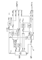
- a second embodiment will be described with reference to FIG.
- Light oil (carbon number: 3) and LPG are mixed with LPG refined by CDU via line 22 and sent to a propylene recovery unit (PRU).
- PRU propylene recovery unit
- Naphtha performs hydrodesulfurization treatment by a hydrodesulfurization apparatus (CCG-HDS in FIG. 2) having a catalyst layer filled with a hydrodesulfurization purification catalyst.
- CCG-HDS hydrodesulfurization apparatus
- a mixed LPG of 30.1 kBD propylene and 27.9 kBD can be obtained.
- the second embodiment is an embodiment in which conventional CDU equipment is used in combination.
- the hydrodesulfurization apparatus (NH-HDS and KR-HDS in FIG. 2) provided with a catalyst layer filled with CDU and hydrodesulfurization purification catalyst used in the second embodiment can use facilities that have been used conventionally. *
- propylene as much as 30.1 kBD can be purified from 200,000 BPSD crude oil.
- a DCFCC having a crude oil processing capacity of 50,000 BPSD is introduced into an existing refinery having a crude oil processing capacity of 150,000 BPSD to increase the crude oil processing capacity to 200,000 BPSD.
- DCFCC the amount of crude oil processed can be increased without modifying existing CDUs.
- the third embodiment is an embodiment using an oil processing apparatus equipped with a CDU and a DCFCC. In processing 200,000 BPSD crude oil, 150.0 kBD crude oil is converted into CDU. The remaining 50.0 kBD crude oil is passed through DCFCC.
- 59.3 kBD atmospheric distillation residue oil obtained by CDU is mixed with 50 kBD crude oil through line 21, and 109.3 kBD crude oil and atmospheric distillation residue oil is mixed with DCFCC.
- Light oil (carbon number: 3) and LPG are mixed with LPG refined by CDU via line 22 and sent to a propylene recovery unit (PRU).
- PRU propylene recovery unit
- Naphtha performs hydrodesulfurization treatment by a hydrodesulfurization apparatus (CCG-HDS in FIG. 3) having a catalyst layer filled with a hydrodesulfurization purification catalyst.
- CCG-HDS hydrodesulfurization apparatus
- 24.4 kBD light oil carbon number: 3
- 22.4 kBD LPG and 3.0 kBD LPG refined by CDU.
- 24.4 kBD of propylene and 22.2 kBD of mixed LPG can be obtained.
- as much as 24.4 kBD of propylene can be purified from 200,000 BPSD of crude oil.
- the fourth embodiment is a petroleum processing apparatus including a prefractionator, a crude oil fluid catalytic cracking reaction apparatus, and a reaction product distillation facility.
- the prefractionator is a distillation column that operates to remove a substance having a low boiling point to some extent. Using a prefractionator, the heavy oil is divided into two fractions, a light fraction from LPG to naphtha and a heavy oil, and the heavy oil is passed through DCFCC.
- the crude oil is passed through the line 11 to the prefractionator.
- the prefractionator it is fractionated into a lighter fraction lighter than naphtha having about 5 to 7 carbon atoms and a heavier heavy oil.
- the light fraction fractionated by the prefractionator enters the reaction product distillation facility via line 15 and is fractionated together with the reaction product by fluid catalytic cracking.
- the heavy oil obtained after passing through the pre-fractionator is passed through the line 13 to the crude oil fluid catalytic cracking reactor to undergo fluid catalytic cracking.
- the components decomposed by the crude oil fluid catalytic cracking reactor are introduced into the reaction product fractionation equipment through the line 14 and distilled. In the same fractionation equipment, it is separated into each fraction such as light gas, LPG, propylene, naphtha, middle distillate, and residual oil according to the boiling point.
- Each separated fraction is subjected to a treatment such as reforming as necessary, and can be appropriately used as a petroleum product base material.
- FIG. 4 shows a comparative example in which the total amount of crude oil of 200,000 BPSD is fractionated by CDU, and the atmospheric residue is decomposed by hydrodesulfurizer and RFCC.
- the amount of propylene refined from the crude oil of 200,000 BPSD was 18.5 kBD, which was a low yield compared to the second to third embodiments.
Landscapes
- Chemical & Material Sciences (AREA)
- Oil, Petroleum & Natural Gas (AREA)
- Engineering & Computer Science (AREA)
- Chemical Kinetics & Catalysis (AREA)
- General Chemical & Material Sciences (AREA)
- Organic Chemistry (AREA)
- Production Of Liquid Hydrocarbon Mixture For Refining Petroleum (AREA)
Abstract
原油又は原油と常圧残渣油との混合油が通油される原油流動接触分解反応装置と、反応生成物蒸留設備と、を備えたことを特徴とする石油の処理装置。
Description
本発明は、石油の処理装置に関する。
従来の一般的な石油精製においては、原油を常圧蒸留装置(Crude Distillation Unit、以下「CDU」と記載する)において常圧蒸留し、軽質ガス、LPG、軽質ナフサ、重質ナフサ、灯油及び軽油などの各留分に分離する。
また、常圧蒸留で生じる常圧残留残渣油の付加価値を高めるべく更に処理する場合には、CDUの下流に残渣油流動接触分解装置(Resid Fluid Catalytic Cracking、以下「RFCC」と記載する)を設けて残渣油の軽質化を行い、ガソリンや軽油留分、ケミカル用途の軽質留分の製造が行われている。
ここで、原油をCDU内の常圧蒸留塔で分留する為には、常圧蒸留塔の上流に原油加熱炉を設け、該加熱炉で燃料を焚いて、約350℃程度まで原油を加熱し、白油留分を蒸発させた後に、常圧蒸留塔に導入する。
このように、石油精製においては、CDUと、RFCCとを備えた設備が一般に用いられる(特許文献1参照)。
また、常圧蒸留で生じる常圧残留残渣油の付加価値を高めるべく更に処理する場合には、CDUの下流に残渣油流動接触分解装置(Resid Fluid Catalytic Cracking、以下「RFCC」と記載する)を設けて残渣油の軽質化を行い、ガソリンや軽油留分、ケミカル用途の軽質留分の製造が行われている。
ここで、原油をCDU内の常圧蒸留塔で分留する為には、常圧蒸留塔の上流に原油加熱炉を設け、該加熱炉で燃料を焚いて、約350℃程度まで原油を加熱し、白油留分を蒸発させた後に、常圧蒸留塔に導入する。
このように、石油精製においては、CDUと、RFCCとを備えた設備が一般に用いられる(特許文献1参照)。
しかし、従来の石油精製設備は、原油加熱炉において膨大なエネルギーを必要とする。石油精製工程において、省エネルギー化することが望まれるが、これまで原油は、まずCDU内の原油加熱炉で加熱された上で分留することが常識とされていた。
本発明者らが鋭意検討した結果、原油を直接RFCCに通油することにより、従来の設備が有していた原油加熱炉を含むCDU相当の設備を省略でき、消費エネルギーを大きく削減できることを見出した。
本発明は消費エネルギーを大きく削減できる石油の処理装置を提供することを課題とする。
本発明は消費エネルギーを大きく削減できる石油の処理装置を提供することを課題とする。
本発明の第1の態様は、原油又は原油と常圧残渣油との混合油が通油される原油流動接触分解反応装置と、反応生成物蒸留設備と、を備えたことを特徴とする石油の処理装置である。
本発明の第2の態様は、プレフラクショネーターと、原油流動接触分解反応装置と、反応生成物蒸留設備と、を備えたことを特徴とする石油の処理装置である。
本発明の第2の態様は、プレフラクショネーターと、原油流動接触分解反応装置と、反応生成物蒸留設備と、を備えたことを特徴とする石油の処理装置である。
本発明によれば、消費エネルギーを大きく削減できる石油の処理装置を提供することができる。
以下、本発明の石油の処理装置の好ましい実施形態について説明する。但し、本発明はこれらの実施形態に限定されない。
<第1実施形態>
第1実施形態は、原油を通油する原油流動接触分解反応装置と、反応生成物蒸留設備と、を備えたことを特徴とする石油の処理装置である
第1実施形態によれば、原油を、原油流動接触分解装置(Direct Crude Fluid Catalytic Cracking、以下「DCFCC」と記載することがある。)に通油して分解し、分解後に反応生成物蒸留設備で蒸留する。
DCFCCは原油を流動接触分解する原油流動接触分解反応装置と、そこからの反応生成物を分留・精製する反応生成物蒸留設備とから構成される。
第1実施形態では、原油をCDUを通さずに直接DCFCCに通油する。この態様においては、従来のように原油加熱炉を含むCDUを設ける必要がないので、CDUにおいて消費されていた分の消費エネルギーを大幅に削減できる。新規に石油精製プラントを建設する際には、建設コストを削減でき、設備面積も小さくすることができる。さらに、既に原油加熱炉を含むCDUが設けられている場合にも、CDUでの処理を行わずに直接DCFCCに通油するようにラインを整備することにより、消費エネルギーを削減できると共に既設CDU関連設備の改造が不要となり製油所全体の増強改造コストの削減にも寄与する。
より具体的には、例えば、100,000BPSDの原油を処理する場合には、CDUに通油する従来の工程に比べて約40MWの燃料消費量を削減することができる。
第1実施形態は、原油を通油する原油流動接触分解反応装置と、反応生成物蒸留設備と、を備えたことを特徴とする石油の処理装置である
第1実施形態によれば、原油を、原油流動接触分解装置(Direct Crude Fluid Catalytic Cracking、以下「DCFCC」と記載することがある。)に通油して分解し、分解後に反応生成物蒸留設備で蒸留する。
DCFCCは原油を流動接触分解する原油流動接触分解反応装置と、そこからの反応生成物を分留・精製する反応生成物蒸留設備とから構成される。
第1実施形態では、原油をCDUを通さずに直接DCFCCに通油する。この態様においては、従来のように原油加熱炉を含むCDUを設ける必要がないので、CDUにおいて消費されていた分の消費エネルギーを大幅に削減できる。新規に石油精製プラントを建設する際には、建設コストを削減でき、設備面積も小さくすることができる。さらに、既に原油加熱炉を含むCDUが設けられている場合にも、CDUでの処理を行わずに直接DCFCCに通油するようにラインを整備することにより、消費エネルギーを削減できると共に既設CDU関連設備の改造が不要となり製油所全体の増強改造コストの削減にも寄与する。
より具体的には、例えば、100,000BPSDの原油を処理する場合には、CDUに通油する従来の工程に比べて約40MWの燃料消費量を削減することができる。
石油処理装置では、通常、原油はCDU内の加熱炉により加熱され、まずCDU内の常圧蒸留塔において沸点の差により、ガス、LPG、ナフサ、灯油、軽油及び残油留分に分離される。これまでの石油の処理装置においては、CDUを備えた設備を設けることが当業者にとって常識であった。
一方で、石油の処理装置において、加熱炉における燃料費が運転費に占める割合が最も大きい。このため、加熱炉での加熱量を削減する事は運転費を左右する重要な要因であった。
一方で、石油の処理装置において、加熱炉における燃料費が運転費に占める割合が最も大きい。このため、加熱炉での加熱量を削減する事は運転費を左右する重要な要因であった。
本発明者らが鋭意検討した結果、驚くべきことに、原油を直接DCFCCに通油した場合に、ナフサやオレフィン等の収量が格段に向上することが見出された。
本実施形態によれば、CDUにおいて消費するエネルギーを大きく削減できるとともに、高い収量でナフサやオレフィン等を得ることができる。
以下、本実施形態について、図面を参照して説明する。
本実施形態によれば、CDUにおいて消費するエネルギーを大きく削減できるとともに、高い収量でナフサやオレフィン等を得ることができる。
以下、本実施形態について、図面を参照して説明する。
第1実施形態は、図1に示すように、原油を通油する原油流動接触分解反応装置と、反応生成物蒸留設備と、を備えている。
第1実施形態では、原油を直接DCFCCに通油し、原油を流動接触分解する。
「流動接触分解」とは、原油と流動状態に保持されている触媒とを接触させ、ガソリンや軽質オレフィンを主体とした軽質な炭化水素に分解することを意味する。
尚、反応器で生成する分解生成物は全てガス状の炭化水素となる。
原油と接触した触媒は、反応によって生じるコークが付着し、反応活性が低下するので、反応器にて反応生成物と分離後に付帯する触媒再生塔に送られて、そこに吹き込まれた空気によってコークを燃焼させて再生される。
DCFCCにおいては、上記の触媒再生時に再生塔で発生する熱を利用して、反応器に通油された原油を蒸発・分解させるので、原油を処理する為にCDUで必要とした原油加熱炉に相当する加熱炉が不要となる。
第1実施形態は、図1に示すように、250℃程度まで予熱した原油をライン11を介して原油流動接触分解装置(DCFCC)に通油する。
第1実施形態では、原油を直接DCFCCに通油し、原油を流動接触分解する。
「流動接触分解」とは、原油と流動状態に保持されている触媒とを接触させ、ガソリンや軽質オレフィンを主体とした軽質な炭化水素に分解することを意味する。
尚、反応器で生成する分解生成物は全てガス状の炭化水素となる。
原油と接触した触媒は、反応によって生じるコークが付着し、反応活性が低下するので、反応器にて反応生成物と分離後に付帯する触媒再生塔に送られて、そこに吹き込まれた空気によってコークを燃焼させて再生される。
DCFCCにおいては、上記の触媒再生時に再生塔で発生する熱を利用して、反応器に通油された原油を蒸発・分解させるので、原油を処理する為にCDUで必要とした原油加熱炉に相当する加熱炉が不要となる。
第1実施形態は、図1に示すように、250℃程度まで予熱した原油をライン11を介して原油流動接触分解装置(DCFCC)に通油する。
DCFCCにおいて、流動接触分解に用いられる触媒としては、例えばシリカ・アルミナ触媒、ゼオライト触媒などが挙げられる。これらの触媒は市販品を用いてもよい。
これらの中でも、エチレン、プロピレン等オレフィン類が高い収量で得られることから、ゼオライト触媒を添加する事が好ましい。
これらの中でも、エチレン、プロピレン等オレフィン類が高い収量で得られることから、ゼオライト触媒を添加する事が好ましい。
DCFCCでは、700℃程度の高温の触媒と接触させて560~570℃の反応温度にて原油を分解する。原油の蒸発や反応に必要な熱は、DCFCCの再生塔で発生する触媒再生時の熱によって賄う。
DCFCCにおける、流動接触分解の反応帯域の出口温度は、500℃以上600℃以下であることが好ましく、520℃以上570℃以下であることがより好ましい。
流動接触分解における原油と触媒の接触時間は、1.5秒以上10秒以下であることが好ましく、2~8秒であることがより好ましい。
DCFCCにおける、流動接触分解の反応帯域の出口温度は、500℃以上600℃以下であることが好ましく、520℃以上570℃以下であることがより好ましい。
流動接触分解における原油と触媒の接触時間は、1.5秒以上10秒以下であることが好ましく、2~8秒であることがより好ましい。
DCFCCにより分解した成分は、ライン12を通じて反応生成物分留設備に導入し、蒸留を行う。同分留設備では、沸点により、軽質ガス、LPG、プロピレン、ナフサ、中間留分、残渣油等の各留分に分離する。分離された各留分は、必要により改質などの処理を行い、それぞれ石油製品基材として適宜用いることができる。
第1実施形態によれば、高い収量でプロピレン等のオレフィン類を得ることができる。例えば、100,000BPSDの原油を第1実施形態で処理する場合には、原料油中のナフサ留分由来のオレフィン類に加え、重油留分の分解により生成するナフサ留分の更なる分解によりプロピレンをはじめとするオレフィン類を得ることができるためである。
従来のCDUと重油脱硫装置とを備えた製油所で精製する場合に比べて、年間約34万トンものプロピレンを増産することができる。
従来のCDUと重油脱硫装置とを備えた製油所で精製する場合に比べて、年間約34万トンものプロピレンを増産することができる。
<第2実施形態>
第2実施形態は、前記第1実施形態と、従来のCDU設備を併用する実施形態である。即ち、第2実施形態は、CDUと、DCFCCと、を備えている。
第2実施形態においては、CDUで得られた常圧蒸留残渣油と、原油とを混合して、DCFCCに通油して分解し、前記分解後に反応生成物蒸留設備で精製する。第2実施形態について、図2を参照して説明する。
第2実施形態は、前記第1実施形態と、従来のCDU設備を併用する実施形態である。即ち、第2実施形態は、CDUと、DCFCCと、を備えている。
第2実施形態においては、CDUで得られた常圧蒸留残渣油と、原油とを混合して、DCFCCに通油して分解し、前記分解後に反応生成物蒸留設備で精製する。第2実施形態について、図2を参照して説明する。
第2実施形態では、200,000BPSDのうち、100,000BPSDをCDUで分解し、残りの100,000BPSDと、CDUで得られた常圧蒸留残渣油とをDCFCCで分解する。
図2に示すように、CDUで得られた39.5kBDの常圧蒸留残渣油を、ライン21を通じて原油と混合し、139.6kBDの原油と常圧蒸留残渣油との混合油をDCFCCに通油する。
図2に示すように、CDUで得られた39.5kBDの常圧蒸留残渣油を、ライン21を通じて原油と混合し、139.6kBDの原油と常圧蒸留残渣油との混合油をDCFCCに通油する。
より具体的には、第2実施形態では、DCFCCに通油された139.5kBDの前記混合油、30.1kBDの軽質油(炭素数;3)と、29.4kBDのLPGと、58.2kBDのナフサと、24.1kBDのLCOと、6.6kBDのDCOとに分解される。
軽質油(炭素数;3)とLPGは、ライン22を介してCDUにより精製されたLPGと混合され、プロピレン回収装置(PRU)に送られる。
ナフサは水素化脱硫精製触媒を充填した触媒層を備えた水素化脱硫装置(図2中のCCG-HDS)により、水素化脱硫処理する。
第2実施形態では、DCFCCにより精製された30.1kBDの軽質油(炭素数;3)と、29.4kBDのLPGと、CDUにより精製された2.0kBDのLPG、との合計62.0kBDから、30.1kBDのプロピレンと、27.9kBDの混合LPGを得ることができる。
第2実施形態では、DCFCCにより精製された30.1kBDの軽質油(炭素数;3)と、29.4kBDのLPGと、CDUにより精製された2.0kBDのLPG、との合計62.0kBDから、30.1kBDのプロピレンと、27.9kBDの混合LPGを得ることができる。
第2実施形態は、従来のCDUの設備を併用する実施形態である。第2実施形態に用いるCDU及び水素化脱硫精製触媒を充填した触媒層を備えた水素化脱硫装置(図2中のNH-HDS及びKR-HDS)は、従来用いられていた設備を利用できる。
第2実施形態によれば、200,000BPSDの原油から、30.1kBDものプロピレンを精製することができる。
<第3実施形態>
第3実施形態は、例えば、原油処理能力が150,000BPSDの既設の製油所に、原油処理能力が50,000BPSDのDCFCCを導入して、原油処理能力を200,000BPSDに増強する実施形態である。DCFCCを導入することにより、既設のCDUの改造をすることなく、原油処理量を増やすことができる。
第3実施形態は、前記第2実施形態と同様に、CDUとDCFCCを備えた石油処理装置を用いた実施形態であって、200,000BPSDの原油を処理するにあたり、150.0kBDの原油をCDUに通油し、残りの50.0kBDの原油をDCFCCに通油する形態である。
第3実施形態を、図3を用いて説明する。
第3実施形態は、例えば、原油処理能力が150,000BPSDの既設の製油所に、原油処理能力が50,000BPSDのDCFCCを導入して、原油処理能力を200,000BPSDに増強する実施形態である。DCFCCを導入することにより、既設のCDUの改造をすることなく、原油処理量を増やすことができる。
第3実施形態は、前記第2実施形態と同様に、CDUとDCFCCを備えた石油処理装置を用いた実施形態であって、200,000BPSDの原油を処理するにあたり、150.0kBDの原油をCDUに通油し、残りの50.0kBDの原油をDCFCCに通油する形態である。
第3実施形態を、図3を用いて説明する。
第3実施形態においては、CDUで得られた59.3kBDの常圧蒸留残渣油を、ライン21を通じて50kBDの原油と混合し、109.3kBDの原油と常圧蒸留残渣油との混合油をDCFCCに通油する。
DCFCCに通油された109.3kBDの前記混合油、24.4kBDの軽質油(炭素数;3)と、22.4kBDのLPGと、49.9kBDのナフサと、17.8kBDのLCOと、5.1kBDのDCOとに分解される。
DCFCCに通油された109.3kBDの前記混合油、24.4kBDの軽質油(炭素数;3)と、22.4kBDのLPGと、49.9kBDのナフサと、17.8kBDのLCOと、5.1kBDのDCOとに分解される。
軽質油(炭素数;3)とLPGは、ライン22を介してCDUにより精製されたLPGと混合され、プロピレン回収装置(PRU)に送られる。
ナフサは水素化脱硫精製触媒を充填した触媒層を備えた水素化脱硫装置(図3中のCCG-HDS)により、水素化脱硫処理する。
第3実施形態では、DCFCCにより精製された24.4kBDの軽質油(炭素数;3)と、22.4kBDのLPGと、CDUにより精製された3.0kBDのLPG、との合計50.6kBDから、24.4kBDのプロピレンと、22.2kBDの混合LPGを得ることができる。
第3実施形態によれば、200,000BPSDの原油から、24.4kBDものプロピレンを精製することができる。
第3実施形態では、DCFCCにより精製された24.4kBDの軽質油(炭素数;3)と、22.4kBDのLPGと、CDUにより精製された3.0kBDのLPG、との合計50.6kBDから、24.4kBDのプロピレンと、22.2kBDの混合LPGを得ることができる。
第3実施形態によれば、200,000BPSDの原油から、24.4kBDものプロピレンを精製することができる。
<第4実施形態>
第4実施形態は、プレフラクショネーターと、原油流動接触分解反応装置と、反応生成物蒸留設備とを備えたことを特徴とする石油の処理装置である。
プレフラクショネーターは、沸点の低い物質をある程度除く操作をする蒸留塔である。プレフラクショネーターで、LPGからナフサまでの軽質留分と重質油の2つの留分に分け、重質油をDCFCCに通油する。
第4実施形態は、プレフラクショネーターと、原油流動接触分解反応装置と、反応生成物蒸留設備とを備えたことを特徴とする石油の処理装置である。
プレフラクショネーターは、沸点の低い物質をある程度除く操作をする蒸留塔である。プレフラクショネーターで、LPGからナフサまでの軽質留分と重質油の2つの留分に分け、重質油をDCFCCに通油する。
図4に示すように、原油をライン11を通じてプレフラクショネーターに通油する。プレフラクショネーターにおいて、炭素数5~7程度以下のナフサより軽い軽質留分と、それより重い重質油とに分留する。プレフラクショネーターで分留された軽質留分は、ライン15を介して反応生成物蒸留設備に入り、流動接触分解による反応生成物と共に分留される。
プレフラクショネーターに通油後に得られた重質油をライン13を通じて原油流動接触分解反応装置に通油し、流動接触分解する。
原油流動接触分解反応装置により分解した成分は、ライン14を通じて反応生成物分留設備に導入し、蒸留を行う。同分留設備では、沸点により、軽質ガス、LPG、プロピレン、ナフサ、中間留分、残渣油等の各留分に分離する。分離された各留分は、必要により改質などの処理を行い、それぞれ石油製品基材として適宜用いることができる。
原油流動接触分解反応装置により分解した成分は、ライン14を通じて反応生成物分留設備に導入し、蒸留を行う。同分留設備では、沸点により、軽質ガス、LPG、プロピレン、ナフサ、中間留分、残渣油等の各留分に分離する。分離された各留分は、必要により改質などの処理を行い、それぞれ石油製品基材として適宜用いることができる。
<比較例1>
図4に、200,000BPSDの原油全量をCDUで分留し、常圧残渣留分を水素化脱硫装置とRFCCで分解する比較例を示す。この場合には、図4に示すとおり、200,000BPSDの原油から精製されるプロピレンの量は18.5kBDと、上記第2~3実施形態に比べて低い収量であった。
図4に、200,000BPSDの原油全量をCDUで分留し、常圧残渣留分を水素化脱硫装置とRFCCで分解する比較例を示す。この場合には、図4に示すとおり、200,000BPSDの原油から精製されるプロピレンの量は18.5kBDと、上記第2~3実施形態に比べて低い収量であった。
本発明によれば、大きく消費エネルギーを削減し、さらに、商品価値の高い軽質留分を高い収量で生産することができる。
Claims (2)
- 原油又は原油と常圧残渣油との混合油が通油される原油流動接触分解反応装置と、反応生成物蒸留設備と、を備えたことを特徴とする石油の処理装置。
- プレフラクショネーターと、原油流動接触分解反応装置と、反応生成物蒸留設備と、を備えたことを特徴とする石油の処理装置。
Priority Applications (2)
| Application Number | Priority Date | Filing Date | Title |
|---|---|---|---|
| JP2018502454A JPWO2017149728A1 (ja) | 2016-03-03 | 2016-03-03 | 石油の処理装置 |
| PCT/JP2016/056627 WO2017149728A1 (ja) | 2016-03-03 | 2016-03-03 | 石油の処理装置 |
Applications Claiming Priority (1)
| Application Number | Priority Date | Filing Date | Title |
|---|---|---|---|
| PCT/JP2016/056627 WO2017149728A1 (ja) | 2016-03-03 | 2016-03-03 | 石油の処理装置 |
Publications (1)
| Publication Number | Publication Date |
|---|---|
| WO2017149728A1 true WO2017149728A1 (ja) | 2017-09-08 |
Family
ID=59742649
Family Applications (1)
| Application Number | Title | Priority Date | Filing Date |
|---|---|---|---|
| PCT/JP2016/056627 Ceased WO2017149728A1 (ja) | 2016-03-03 | 2016-03-03 | 石油の処理装置 |
Country Status (2)
| Country | Link |
|---|---|
| JP (1) | JPWO2017149728A1 (ja) |
| WO (1) | WO2017149728A1 (ja) |
Citations (3)
| Publication number | Priority date | Publication date | Assignee | Title |
|---|---|---|---|---|
| JPH01304183A (ja) * | 1988-03-25 | 1989-12-07 | Amoco Corp | 未精製原油の接触分解方法 |
| JP2000336375A (ja) * | 1999-05-05 | 2000-12-05 | Bar Co Processes Joint Venture | 改良された高転化率の残油流動接触分解方法 |
| JP2007501311A (ja) * | 2003-08-04 | 2007-01-25 | ストーン アンド ウェブスター プロセス テクノロジー インコーポレーテッド | 触媒ストリッパー中の触媒温度の制御 |
-
2016
- 2016-03-03 JP JP2018502454A patent/JPWO2017149728A1/ja active Pending
- 2016-03-03 WO PCT/JP2016/056627 patent/WO2017149728A1/ja not_active Ceased
Patent Citations (3)
| Publication number | Priority date | Publication date | Assignee | Title |
|---|---|---|---|---|
| JPH01304183A (ja) * | 1988-03-25 | 1989-12-07 | Amoco Corp | 未精製原油の接触分解方法 |
| JP2000336375A (ja) * | 1999-05-05 | 2000-12-05 | Bar Co Processes Joint Venture | 改良された高転化率の残油流動接触分解方法 |
| JP2007501311A (ja) * | 2003-08-04 | 2007-01-25 | ストーン アンド ウェブスター プロセス テクノロジー インコーポレーテッド | 触媒ストリッパー中の触媒温度の制御 |
Also Published As
| Publication number | Publication date |
|---|---|
| JPWO2017149728A1 (ja) | 2018-12-27 |
Similar Documents
| Publication | Publication Date | Title |
|---|---|---|
| JP6970185B2 (ja) | 供給原料炭化水素を石油化学製品へ転換するためのシステムおよび方法 | |
| JP7281473B2 (ja) | 高過酷度流動接触分解システムおよび石油供給物からのオレフィンの生成プロセス | |
| KR102201157B1 (ko) | 원유의 고 강도 촉매 크래킹 공정 | |
| KR102375080B1 (ko) | 나프타 종류의 공급원료를 처리하는 방향족 컴플렉스 및 촉매 개질 유닛과 결합하여, 고도로 수소처리된 vgo 종류의 중질 공급원료를 처리하는 fcc 유닛을 사용하여 경질 올레핀들 및 btx 를 제조하는 방법 | |
| JP4620427B2 (ja) | オレフィンのための統合された接触分解および水蒸気熱分解法 | |
| JP6490008B2 (ja) | 熱を用いた水蒸気分解によってオレフィン含有生成物を製造する方法 | |
| JP6215936B2 (ja) | 炭化水素供給原料の熱水蒸気分解による転化方法 | |
| KR102413259B1 (ko) | 원유를 프로필렌 수율이 향상된 석유화학물질로 변환시키기 위한 방법 및 장치 | |
| RU2700710C1 (ru) | Способ переработки сырой нефти в легкие олефины, ароматические соединения и синтетический газ | |
| JP6267694B2 (ja) | 温度勾配過程による原油の直接接触分解 | |
| JP6543501B2 (ja) | ナフサ系フィードを処理する接触分解装置(ncc)と接触改質装置とアロマティクス・コンプレックスとを用いる軽質オレフィンおよびbtxの製造方法 | |
| JP6181181B2 (ja) | 分解炉における熱水蒸気分解によってオレフィンを製造する方法 | |
| EA017596B1 (ru) | Дополнительный крекинг парафинового лигроина при совместной работе установки каталитического крекинга в псевдоожиженном слое | |
| JP2013536249A (ja) | 製油所オフガス及び他の軽質炭化水素の希釈供給原料分解によるオレフィン製造方法 | |
| JP2017502110A (ja) | 軽質オレフィンの製造のための溶剤脱瀝および流動接触分解の統合された方法 | |
| JP2015524451A (ja) | 熱水蒸気分解によるオレフィンの製造方法 | |
| US12122963B2 (en) | Naphtha catalytic cracking process | |
| WO2017149728A1 (ja) | 石油の処理装置 | |
| WO2000069992A1 (fr) | Procede de raffinage de petrol brut | |
| ES2916256T3 (es) | Procedimiento de craqueo catalítico fluido | |
| TW202419614A (zh) | 來自常壓蒸餾之回收物萃餘物及石腦油的催化重組 | |
| TW202540394A (zh) | 熱裂解冷凝物以產生烯烴及柴油之技術 | |
| JP2012121937A (ja) | 炭化水素類の製造方法 |
Legal Events
| Date | Code | Title | Description |
|---|---|---|---|
| ENP | Entry into the national phase |
Ref document number: 2018502454 Country of ref document: JP Kind code of ref document: A |
|
| NENP | Non-entry into the national phase |
Ref country code: DE |
|
| 121 | Ep: the epo has been informed by wipo that ep was designated in this application |
Ref document number: 16892568 Country of ref document: EP Kind code of ref document: A1 |
|
| 122 | Ep: pct application non-entry in european phase |
Ref document number: 16892568 Country of ref document: EP Kind code of ref document: A1 |