WO2017149638A1 - 充放電装置 - Google Patents
充放電装置 Download PDFInfo
- Publication number
- WO2017149638A1 WO2017149638A1 PCT/JP2016/056186 JP2016056186W WO2017149638A1 WO 2017149638 A1 WO2017149638 A1 WO 2017149638A1 JP 2016056186 W JP2016056186 W JP 2016056186W WO 2017149638 A1 WO2017149638 A1 WO 2017149638A1
- Authority
- WO
- WIPO (PCT)
- Prior art keywords
- charging
- power
- charge
- control unit
- information
- Prior art date
Links
Images


Classifications
-
- B—PERFORMING OPERATIONS; TRANSPORTING
- B60—VEHICLES IN GENERAL
- B60L—PROPULSION OF ELECTRICALLY-PROPELLED VEHICLES; SUPPLYING ELECTRIC POWER FOR AUXILIARY EQUIPMENT OF ELECTRICALLY-PROPELLED VEHICLES; ELECTRODYNAMIC BRAKE SYSTEMS FOR VEHICLES IN GENERAL; MAGNETIC SUSPENSION OR LEVITATION FOR VEHICLES; MONITORING OPERATING VARIABLES OF ELECTRICALLY-PROPELLED VEHICLES; ELECTRIC SAFETY DEVICES FOR ELECTRICALLY-PROPELLED VEHICLES
- B60L50/00—Electric propulsion with power supplied within the vehicle
- B60L50/50—Electric propulsion with power supplied within the vehicle using propulsion power supplied by batteries or fuel cells
-
- B—PERFORMING OPERATIONS; TRANSPORTING
- B60—VEHICLES IN GENERAL
- B60L—PROPULSION OF ELECTRICALLY-PROPELLED VEHICLES; SUPPLYING ELECTRIC POWER FOR AUXILIARY EQUIPMENT OF ELECTRICALLY-PROPELLED VEHICLES; ELECTRODYNAMIC BRAKE SYSTEMS FOR VEHICLES IN GENERAL; MAGNETIC SUSPENSION OR LEVITATION FOR VEHICLES; MONITORING OPERATING VARIABLES OF ELECTRICALLY-PROPELLED VEHICLES; ELECTRIC SAFETY DEVICES FOR ELECTRICALLY-PROPELLED VEHICLES
- B60L53/00—Methods of charging batteries, specially adapted for electric vehicles; Charging stations or on-board charging equipment therefor; Exchange of energy storage elements in electric vehicles
- B60L53/10—Methods of charging batteries, specially adapted for electric vehicles; Charging stations or on-board charging equipment therefor; Exchange of energy storage elements in electric vehicles characterised by the energy transfer between the charging station and the vehicle
- B60L53/14—Conductive energy transfer
-
- B—PERFORMING OPERATIONS; TRANSPORTING
- B60—VEHICLES IN GENERAL
- B60L—PROPULSION OF ELECTRICALLY-PROPELLED VEHICLES; SUPPLYING ELECTRIC POWER FOR AUXILIARY EQUIPMENT OF ELECTRICALLY-PROPELLED VEHICLES; ELECTRODYNAMIC BRAKE SYSTEMS FOR VEHICLES IN GENERAL; MAGNETIC SUSPENSION OR LEVITATION FOR VEHICLES; MONITORING OPERATING VARIABLES OF ELECTRICALLY-PROPELLED VEHICLES; ELECTRIC SAFETY DEVICES FOR ELECTRICALLY-PROPELLED VEHICLES
- B60L53/00—Methods of charging batteries, specially adapted for electric vehicles; Charging stations or on-board charging equipment therefor; Exchange of energy storage elements in electric vehicles
- B60L53/60—Monitoring or controlling charging stations
- B60L53/66—Data transfer between charging stations and vehicles
-
- H—ELECTRICITY
- H02—GENERATION; CONVERSION OR DISTRIBUTION OF ELECTRIC POWER
- H02J—CIRCUIT ARRANGEMENTS OR SYSTEMS FOR SUPPLYING OR DISTRIBUTING ELECTRIC POWER; SYSTEMS FOR STORING ELECTRIC ENERGY
- H02J7/00—Circuit arrangements for charging or depolarising batteries or for supplying loads from batteries
- H02J7/02—Circuit arrangements for charging or depolarising batteries or for supplying loads from batteries for charging batteries from ac mains by converters
-
- B—PERFORMING OPERATIONS; TRANSPORTING
- B60—VEHICLES IN GENERAL
- B60L—PROPULSION OF ELECTRICALLY-PROPELLED VEHICLES; SUPPLYING ELECTRIC POWER FOR AUXILIARY EQUIPMENT OF ELECTRICALLY-PROPELLED VEHICLES; ELECTRODYNAMIC BRAKE SYSTEMS FOR VEHICLES IN GENERAL; MAGNETIC SUSPENSION OR LEVITATION FOR VEHICLES; MONITORING OPERATING VARIABLES OF ELECTRICALLY-PROPELLED VEHICLES; ELECTRIC SAFETY DEVICES FOR ELECTRICALLY-PROPELLED VEHICLES
- B60L2210/00—Converter types
- B60L2210/30—AC to DC converters
-
- H—ELECTRICITY
- H02—GENERATION; CONVERSION OR DISTRIBUTION OF ELECTRIC POWER
- H02J—CIRCUIT ARRANGEMENTS OR SYSTEMS FOR SUPPLYING OR DISTRIBUTING ELECTRIC POWER; SYSTEMS FOR STORING ELECTRIC ENERGY
- H02J2207/00—Indexing scheme relating to details of circuit arrangements for charging or depolarising batteries or for supplying loads from batteries
- H02J2207/20—Charging or discharging characterised by the power electronics converter
-
- H—ELECTRICITY
- H02—GENERATION; CONVERSION OR DISTRIBUTION OF ELECTRIC POWER
- H02J—CIRCUIT ARRANGEMENTS OR SYSTEMS FOR SUPPLYING OR DISTRIBUTING ELECTRIC POWER; SYSTEMS FOR STORING ELECTRIC ENERGY
- H02J2310/00—The network for supplying or distributing electric power characterised by its spatial reach or by the load
- H02J2310/10—The network having a local or delimited stationary reach
- H02J2310/20—The network being internal to a load
- H02J2310/22—The load being a portable electronic device
-
- H—ELECTRICITY
- H02—GENERATION; CONVERSION OR DISTRIBUTION OF ELECTRIC POWER
- H02J—CIRCUIT ARRANGEMENTS OR SYSTEMS FOR SUPPLYING OR DISTRIBUTING ELECTRIC POWER; SYSTEMS FOR STORING ELECTRIC ENERGY
- H02J2310/00—The network for supplying or distributing electric power characterised by its spatial reach or by the load
- H02J2310/40—The network being an on-board power network, i.e. within a vehicle
- H02J2310/48—The network being an on-board power network, i.e. within a vehicle for electric vehicles [EV] or hybrid vehicles [HEV]
-
- Y—GENERAL TAGGING OF NEW TECHNOLOGICAL DEVELOPMENTS; GENERAL TAGGING OF CROSS-SECTIONAL TECHNOLOGIES SPANNING OVER SEVERAL SECTIONS OF THE IPC; TECHNICAL SUBJECTS COVERED BY FORMER USPC CROSS-REFERENCE ART COLLECTIONS [XRACs] AND DIGESTS
- Y02—TECHNOLOGIES OR APPLICATIONS FOR MITIGATION OR ADAPTATION AGAINST CLIMATE CHANGE
- Y02T—CLIMATE CHANGE MITIGATION TECHNOLOGIES RELATED TO TRANSPORTATION
- Y02T10/00—Road transport of goods or passengers
- Y02T10/60—Other road transportation technologies with climate change mitigation effect
- Y02T10/70—Energy storage systems for electromobility, e.g. batteries
-
- Y—GENERAL TAGGING OF NEW TECHNOLOGICAL DEVELOPMENTS; GENERAL TAGGING OF CROSS-SECTIONAL TECHNOLOGIES SPANNING OVER SEVERAL SECTIONS OF THE IPC; TECHNICAL SUBJECTS COVERED BY FORMER USPC CROSS-REFERENCE ART COLLECTIONS [XRACs] AND DIGESTS
- Y02—TECHNOLOGIES OR APPLICATIONS FOR MITIGATION OR ADAPTATION AGAINST CLIMATE CHANGE
- Y02T—CLIMATE CHANGE MITIGATION TECHNOLOGIES RELATED TO TRANSPORTATION
- Y02T10/00—Road transport of goods or passengers
- Y02T10/60—Other road transportation technologies with climate change mitigation effect
- Y02T10/7072—Electromobility specific charging systems or methods for batteries, ultracapacitors, supercapacitors or double-layer capacitors
-
- Y—GENERAL TAGGING OF NEW TECHNOLOGICAL DEVELOPMENTS; GENERAL TAGGING OF CROSS-SECTIONAL TECHNOLOGIES SPANNING OVER SEVERAL SECTIONS OF THE IPC; TECHNICAL SUBJECTS COVERED BY FORMER USPC CROSS-REFERENCE ART COLLECTIONS [XRACs] AND DIGESTS
- Y02—TECHNOLOGIES OR APPLICATIONS FOR MITIGATION OR ADAPTATION AGAINST CLIMATE CHANGE
- Y02T—CLIMATE CHANGE MITIGATION TECHNOLOGIES RELATED TO TRANSPORTATION
- Y02T90/00—Enabling technologies or technologies with a potential or indirect contribution to GHG emissions mitigation
- Y02T90/10—Technologies relating to charging of electric vehicles
- Y02T90/12—Electric charging stations
-
- Y—GENERAL TAGGING OF NEW TECHNOLOGICAL DEVELOPMENTS; GENERAL TAGGING OF CROSS-SECTIONAL TECHNOLOGIES SPANNING OVER SEVERAL SECTIONS OF THE IPC; TECHNICAL SUBJECTS COVERED BY FORMER USPC CROSS-REFERENCE ART COLLECTIONS [XRACs] AND DIGESTS
- Y02—TECHNOLOGIES OR APPLICATIONS FOR MITIGATION OR ADAPTATION AGAINST CLIMATE CHANGE
- Y02T—CLIMATE CHANGE MITIGATION TECHNOLOGIES RELATED TO TRANSPORTATION
- Y02T90/00—Enabling technologies or technologies with a potential or indirect contribution to GHG emissions mitigation
- Y02T90/10—Technologies relating to charging of electric vehicles
- Y02T90/14—Plug-in electric vehicles
-
- Y—GENERAL TAGGING OF NEW TECHNOLOGICAL DEVELOPMENTS; GENERAL TAGGING OF CROSS-SECTIONAL TECHNOLOGIES SPANNING OVER SEVERAL SECTIONS OF THE IPC; TECHNICAL SUBJECTS COVERED BY FORMER USPC CROSS-REFERENCE ART COLLECTIONS [XRACs] AND DIGESTS
- Y02—TECHNOLOGIES OR APPLICATIONS FOR MITIGATION OR ADAPTATION AGAINST CLIMATE CHANGE
- Y02T—CLIMATE CHANGE MITIGATION TECHNOLOGIES RELATED TO TRANSPORTATION
- Y02T90/00—Enabling technologies or technologies with a potential or indirect contribution to GHG emissions mitigation
- Y02T90/10—Technologies relating to charging of electric vehicles
- Y02T90/16—Information or communication technologies improving the operation of electric vehicles
Definitions
- This invention relates to the charging / discharging apparatus connected to the storage battery mounted in a motor vehicle.
- V2H Vehicle to Home
- the electric power supplied from the electric vehicle is an emergency power source in the event of a power failure. It is expected to be part of an energy management system in conjunction with a power source for peak cuts of quantity or solar power generation. From the above, it is expected that the charging / discharging device will be increasingly popular in homes or public facilities.
- Patent Document 1 discloses a technology that enables charging and discharging of a storage battery mounted on an electric vehicle.
- the charging / discharging device shown in Patent Document 1 determines whether or not charging is possible by communication between the electric vehicle and the charging / discharging device, and when the user removes the connector from the DC (Direct Current) inlet, the voltage of the storage battery is applied. The DC inlet terminal is prevented from being exposed.
- DC Direct Current
- a storage battery mounted on a car is charged with a charging / discharging device that does not support a charging method according to the characteristics of the storage battery, the charging / discharging device or the storage battery is compared with a case of charging with a charging / discharging device corresponding to the storage battery. Therefore, the performance deteriorates at a significantly high speed, and the amount of power discharged from the storage battery and the amount of power charged to the storage battery are lower than the desired amount of power.
- Patent Literature 1 does not disclose a method for determining whether or not charging is possible according to the characteristics of the storage battery, a charging / discharging device that determines whether or not the storage battery can be charged even when the automobile permits charging. Development of was desired.
- This invention is made in view of the above, Comprising: It aims at obtaining the charging / discharging apparatus which can suppress the deterioration of the performance of the storage battery mounted in a motor vehicle.
- the charging / discharging device of the present invention controls a power conversion unit that converts AC power into DC power and supplies it to a secondary battery in an automobile, and the power conversion unit. And a control unit that transmits information to and from the automobile, and the control unit includes correspondence information indicating that the control unit is compatible with a charging method according to the characteristics of the secondary battery. Using the non-corresponding information indicating that the charging method is not supported, whether to charge the secondary battery in the automobile connected to the charging / discharging device is determined.
- the present invention it is possible to suppress the deterioration of the performance of the storage battery mounted on the automobile.
- the block diagram of the charging / discharging system using the charging / discharging apparatus which concerns on embodiment of this invention The sequence chart which shows operation
- compatible table set to the control part in the charging / discharging apparatus shown by FIG. The figure for demonstrating the process which determines chargeability based on the power source specific table shown by FIG. 7, and the charge system corresponding
- FIG. 1 is a configuration diagram of a charge / discharge system using a charge / discharge device according to an embodiment of the present invention.
- a charge / discharge system 300 shown in FIG. 1 includes an electric vehicle 100 and a charge / discharge device 200 connected to the electric vehicle 100. In this embodiment, the charge / discharge system 300 using the electric vehicle 100 will be described. However, the vehicle applicable to the charge / discharge system 300 is not limited to the electric vehicle 100, and can be charged by the charge / discharge device 200. Any vehicle including a secondary battery as the power supply source 101 may be used, and a hybrid car, an plug-in hybrid car, or a range extender EV (Electric Vehicles) equipped with an internal combustion engine may be used.
- a hybrid car, an plug-in hybrid car, or a range extender EV (Electric Vehicles) equipped with an internal combustion engine may be used.
- the electric vehicle 100 includes a power supply source 101, a control unit 102, a conductor 103, and an inlet 104.
- the charging / discharging device 200 includes a power conversion unit 201, a control unit 202, an interconnection switch 203, and a charging / discharging connector 204.
- the power line 210 in the charging / discharging device 200 is connected to the power line 113 in the electric vehicle 100, and the signal line 211 in the charging / discharging device 200 is connected to the electric vehicle.
- the communication line 212 in the charging / discharging device 200 is connected to the communication line 112 in the electric vehicle 100.
- One end of a power line 210, a signal line 211, and a communication line 212 is connected to the charge / discharge connector 204 of the charge / discharge device 200.
- the other end of the power line 210 is connected to the DC end side of the power conversion unit 201, and the other ends of the signal line 211 and the communication line 212 are connected to the control unit 202.
- the AC end side of the power conversion unit 201 is connected to the distribution board 20 via the interconnection switch 203.
- a load 30 and the power system 10 are connected to the distribution board 20. Examples of the load 30 include home appliances such as an air conditioner, a refrigerator, and an illumination driven by AC power.
- the power line 113, the signal line 111, and one end of the communication line 112 are connected to the inlet 104 of the electric vehicle 100.
- the conductor 103 is disposed between the power supply source 101 and the inlet 104, the other end of the power line 113 is connected to one end of the conductor 103, and one end of the power line 110 is connected to the other end of the conductor 103.
- the other end of the power line 110 is connected to the power supply source 101, and the other ends of the signal line 111 and the communication line 112 are connected to the control unit 102.
- the communication line 112 communicates information related to charging / discharging of the power supply source 101 between the electric vehicle 100 and the charging / discharging device 200.
- a communication method a communication protocol of CAN (Controller Area Network) is used. The thing can be illustrated.
- the conductor 103 is a relay that conducts the power line 110 and the power line 113 when both the control unit 202 in the charging / discharging device 200 and the control unit 102 in the electric vehicle 100 are allowed to charge / discharge.
- the relay inside the conductor 103 operates.
- a connection permission signal for permitting connection of the charging / discharging device 200 to the electric vehicle 100 is supplied from the outside, a voltage is applied to the signal line 211 and the signal line 111, the coil in the conductor 103 is excited, and the conductor 103 The plunger inside is aspirated.
- the power line 113 and the power line 110 become conductive, and the power stored in the charge / discharge device 200 can be discharged and the power supply source 101 can be charged.
- the power supply source 101 is connected to the inlet 104 via the power line 110, the conductor 103, and the power line 113.
- the power stored in the power supply source 101 is supplied to the power conversion unit 201 in the charging / discharging device 200 via the power line 110, the conductor 103, the power line 113, the inlet 104, the charging / discharging connector 204 and the power line 210.
- DC power output from the power conversion unit 201 is supplied to the power supply source 101 via the power line 210, the charge / discharge connector 204, the inlet 104, the power line 113, the conductor 103, and the power line 110.
- Examples of the power supply source 101 include a nickel metal hydride storage battery, a lithium ion storage battery, and a lithium ion polymer storage battery.
- the type of the power supply source 101 is not limited to these, and any type of secondary battery that can be charged by the charging / discharging device 200 may be used.
- the power supply source 101 is used for the following purposes. (1) A power supply source 101 mounted on an automobile having an internal combustion engine stores power generated by an alternator driven by the internal combustion engine, and temporarily supplies power to the load 30 when the capacity is relatively large. It can also be used as a source.
- the power supply source 101 mounted on the plug-in hybrid car or the hybrid car supplies power to the traveling motor or stores power regenerated by the motor and is also used as a power supply source to the load 30 Is possible.
- the power supply source 101 mounted on the electric vehicle 100 supplies power to the traveling motor or stores power regenerated by the motor, and can also be used as a power supply source for the load 30.
- the control unit 102 has a communication function for transmitting and receiving various types of information to and from the control unit 202 in the charge / discharge device 200 via the communication line 112.
- the power conversion unit 201 is a bidirectional power conversion unit having a DCAC (Direct Current to Alternate Current) conversion function and an ACDC (Alternating Current to Direct Current) conversion function.
- DCAC Direct Current to Alternate Current
- ACDC Alternating Current to Direct Current
- the control unit 202 has a function of controlling the operation of the power conversion unit 201 and monitoring current and voltage in the charge / discharge path using a measuring instrument (not shown) to detect abnormalities such as overcurrent and overvoltage.
- the control unit 202 has various communication functions performed with the control unit 102 via the communication lines 112 and 212. In addition, when charging / discharging, the control unit 202 performs control to turn on the conductor 103 and the interconnection switch 203 in order to connect the distribution board 20 and the power supply source 101.
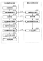
- FIG. 2 is a sequence chart showing the operation of the charging / discharging device and the electric vehicle according to the embodiment of the present invention.
- the control unit 202 of the charge / discharge device 200 starts a charge / discharge start sequence. For example, when a charge / discharge start command output from a controller (not shown) is input to the charge / discharge device 200, the charge / discharge start sequence is started.
- the control unit 202 outputs a charge / discharge start signal T10 to notify the electric vehicle 100 of the start of charge / discharge.
- the charge / discharge start signal T10 is received by the control unit 102 via the communication lines 112 and 212.
- the control unit 202 that has output the charge / discharge start signal T10 enters a communication standby state in the electric vehicle 100 and the charge / discharge device 200 in S103.
- the control unit 102 that has received the charge / discharge start signal T10 in S201 detects the start of charge / discharge, and the control unit 102 that has detected the start of charge / discharge enters a communication standby state in the electric vehicle 100 and the charge / discharge device 200 in S202, and is ready for communication.
- the signal T11 is output.
- the communication preparation completion signal T11 is received by the control unit 102 via the communication lines 112 and 212.
- step S104 and S203 the control unit 102 that has entered the communication standby state and the control unit 202 that has received the communication preparation completion signal T11 perform exchange processing of the charge / discharge information T12 via the communication lines 112 and 212.
- the charge / discharge information T12 for example, on the electric vehicle 100 side, the remaining amount of electric power, the charge / discharge current upper limit value, and the charge / discharge voltage upper and lower limit values, which are information related to the power supply source 101, are considered.
- the charge / discharge information T12 may be an input / output possible voltage value and an input / output possible current value that are information related to the power conversion unit 201 on the charge / discharge device 200 side.
- control unit 202 performs chargeability determination processing using information regarding the power supply source 101 obtained in the charge / discharge information exchange processing in S104. Details of the chargeability determination process will be described later.
- the control unit 202 that has determined that charging / discharging is possible in S105 transmits a charge / discharge preparation completion signal T13 to the control unit 102 in S106.
- the control unit 102 that has received the charge / discharge preparation completion signal T13 puts the conductor 103 into the input state in S204.
- control unit 202 After the control unit 202 confirms the insertion of the conductor 103 in S107, the control unit 202 starts the charge / discharge operation by controlling the power conversion unit 201 in S108. That is, the control unit 202 causes the power conversion unit 201 to perform an ACDC conversion operation or a DCAC conversion operation.
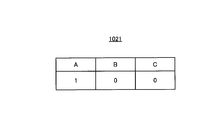
- FIG. 3 is a diagram showing an example of a battery identification table set in the control unit in the electric vehicle shown in FIG.
- the type of one or more secondary batteries mounted on the electric vehicle 100 is associated with identification information that identifies the presence or absence of one or more secondary batteries.
- three types of secondary batteries A, B, and C are associated with information indicating the presence or absence of each of the three types of secondary batteries A, B, and C.
- the secondary battery A is a nickel hydride storage battery
- the secondary battery B is a lithium ion storage battery
- the secondary battery C is a lithium ion polymer storage battery.
- “1” represents that the corresponding secondary battery is mounted in the electric vehicle 100 having the battery identification table 1021.
- “0” represents that the corresponding secondary battery is not mounted in the electric vehicle 100 having the battery identification table 1021.
- the battery identification table 1021 is stored in a storage unit (not shown) that constitutes the control unit 102. Information regarding the battery identification table 1021 included in the control unit 102 is transmitted to the control unit 202 via the communication lines 112 and 212 in S104 illustrated in FIG. 2, for example.
- the battery specification table 1021 information related to the three secondary batteries A, B, and C is recorded in the battery specification table 1021, but specific information related to storage batteries other than these secondary batteries may be recorded in the battery specification table 1021.
- the battery identification table 1021 may record identification information regarding one secondary battery instead of the identification information regarding the plurality of secondary batteries A, B, and C.
- FIG. 4 is a diagram showing an example of a charging method correspondence table set in the control unit in the charging / discharging device shown in FIG.
- the charging method correspondence table 2021 shown in FIG. 4 charging according to the type of one or more secondary batteries mounted on the electric vehicle 100 and the characteristics of the one or more secondary batteries mounted on the electric vehicle 100 is performed.
- Correspondence information “1” indicating that the system is supported is associated with non-corresponding information “0” indicating that the system is not compatible with the charging system.
- the charging method correspondence table 2021 is stored in a storage unit (not shown) constituting the control unit 202. Information related to the charging method correspondence table 2021 included in the control unit 202 is transmitted to the control unit 102 via the communication lines 112 and 212 in S104 illustrated in FIG.
- correspondence information and non-correspondence information about the three secondary batteries A, B, and C are recorded in the charging method correspondence table 2021, but the charging method correspondence table 2021 relates to storage batteries other than these secondary batteries. Corresponding information and non-corresponding information may be recorded.
- the charging method correspondence table 2021 may record correspondence information or non-correspondence information regarding one secondary battery instead of correspondence information and non-correspondence information regarding the plurality of secondary batteries A, B, and C.
- FIG. 5 is a diagram for explaining processing for determining whether or not charging is possible based on the battery identification table shown in FIG. 3 and the charging method correspondence table shown in FIG. FIG. 5 shows, as an example, information on three secondary batteries A, B, and C recorded on each of 27 types of battery specifying tables 1021 and information on the charging method correspondence table 2021.
- “ ⁇ ” Means that either the chargeable information “1” or the non-chargeable information “0” may be used.
- the information corresponding to the secondary batteries A, B, and C shown in the column 1 is connected to the information in the battery specification table 1021 of the first automobile among the plurality of electric automobiles 100 and the first automobile.
- the information corresponding to the secondary batteries A, B, and C shown in the column 2 includes information in the battery specification table 1021 included in a second vehicle different from the first vehicle among the plurality of electric vehicles 100, and This is information in the charging method correspondence table 2021 included in the charging / discharging device 200 connected to the second automobile.
- Whether or not charging is possible is determined by the logical product of the information corresponding to the same type of secondary battery in the information on the secondary battery shown in the battery identification table 1021 and the information on the secondary battery shown in the charging method correspondence table 2021. When it is “1”, it is determined as “chargeable”, and when the logical product of information corresponding to the same type of secondary battery is “0”, it is determined as “not chargeable”.
- the information of the secondary battery A in the battery identification table 1021 is “1”, and the secondary battery A in the charging method correspondence table 2021 included in the charging / discharging device 200 connected to the electric vehicle 100 having the battery identification table 1021. If the information is “1”, the charging / discharging device 200 determines that charging is possible because the charging / discharging device 200 corresponds to the charging method according to the characteristics of the power supply source 101 mounted on the electric vehicle 100.
- No. A method for determining whether or not charging is possible will be described using the information shown in the column 4 as an example.
- the information of the secondary battery B in the battery identification table 1021 is “1”, and the secondary battery B in the charging method correspondence table 2021 included in the charging / discharging device 200 connected to the electric vehicle 100 having the battery identification table 1021. Is “0”, the charging / discharging device 200 determines that charging is not possible because the charging / discharging device 200 does not support the charging method according to the characteristics of the power supply source 101 mounted on the electric vehicle 100.
- FIG. 6 is a flowchart of chargeability determination processing in S105 shown in FIG.
- the control unit 202 determines chargeability based on the chargeability correspondence table shown in FIG. 5 in S301 of FIG.
- the control part 202 has received the charge instruction
- the control unit 202 notifies the control unit 102 of the end of charging / discharging, and charging / discharging control on the electric vehicle side. End.
- step S304 the control unit 202 notifies the user that the electric vehicle 100 connected to the charging / discharging device 200 is equipped with a power supply source 101 that cannot be charged.
- the charging / discharging device is currently connected. Is not supported for charging an electric vehicle.
- the message information is transmitted to a controller (not shown) that controls the charging / discharging device 200, and the controller that has received the message information displays the message as character information on a display screen provided in the controller. .
- control unit 202 that has completed the notification to the user ends the charge availability determination process in S305.
- control unit 202 ends the charging permission determination process in S306, and performs the processing after S106 in FIG.
- control unit 202 ends the charging permission determination process in S306, and performs the processes after S106 in FIG.
- the charging / discharging device 200 corresponds to the correspondence information indicating that the charging method corresponds to the characteristic of the power supply source 101 that is a secondary battery, and the charging method. It is configured to determine whether or not the secondary battery in the electric vehicle 100 that is an automobile connected to the charging / discharging device 200 can be charged using non-corresponding information indicating that the charging / discharging apparatus 200 is not used. As a result, charging of the power supply source 101 that does not correspond to the charging method according to the characteristics of the power supply source 101 can be prevented, and performance deterioration of the power supply source 101 or the charging / discharging device 200 can be suppressed. Further, by performing the chargeability determination process before the conductor 103 is turned on, it is possible to prevent the power stored in the power supply source 101 from being output to the outside.
- the power supply source 101 mounted on the electric vehicle 100 is a secondary battery such as a nickel metal hydride storage battery, a lithium ion storage battery, or a lithium ion polymer storage battery has been described.
- power sources such as an internal combustion engine and a fuel cell are mounted.
- charging / discharging device 200 according to the present embodiment is connected to an automobile equipped with at least one of these power sources, it is also possible to determine whether or not the power source installed in the automobile can be charged. is there.
- a specific example will be described below.
- FIG. 7 is a diagram showing an example of a power source specifying table set in a control unit of a vehicle equipped with a power source such as a secondary battery, an internal combustion engine, or a fuel cell instead of the electric vehicle shown in FIG.
- a power source such as a secondary battery, an internal combustion engine, or a fuel cell instead of the electric vehicle shown in FIG.
- the power source specification table 1021A shown in FIG. 7 is associated with the type of power source mounted on the automobile and specific information for specifying the presence or absence of the power source.
- three types of power sources are associated with information indicating the presence or absence of each of the three types of power sources.
- A1 is a secondary battery
- B1 is an internal combustion engine
- C1 is a fuel cell.
- the power source illustrated here is an example and is not limited thereto. “1” represents that the corresponding power source is mounted in the automobile having the power source specifying table 1021A. “0” represents that the corresponding power source is not mounted in the automobile having the power source specifying table 1021A.
- the power source identification table 1021 ⁇ / b> A is stored in a storage unit (not shown) that constitutes the control unit 102. Information relating to the power source identification table 1021A included in the control unit 102 is transmitted to the control unit 202 via the communication lines 112 and 212, for example, in S104 illustrated in FIG.
- FIG. 8 is a view showing a modification of the charging method correspondence table set in the control unit in the charging / discharging device shown in FIG.
- the charging method correspondence table 2021A shown in FIG. 8 includes the type of power source mounted on the vehicle, chargeable information “1” indicating that the power source mounted on the vehicle can be charged, and the power The charge disable information “0” indicating that the source cannot be charged is associated.
- the charging method correspondence table 2021A is stored in a storage unit (not shown) constituting the control unit 202. Information regarding the charging method correspondence table 2021A included in the control unit 202 is transmitted to the control unit 102 via the communication lines 112 and 212 in S104 illustrated in FIG.
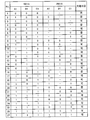
- FIG. 9 is a diagram for explaining processing for determining whether or not charging is possible based on the power source specifying table shown in FIG. 7 and the charging method correspondence table shown in FIG. In FIG. 5, as an example, three power sources A1, B1, C1 and information on the charging method correspondence table 2021A recorded in each of the 27 types of power source specifying tables 1021A are shown. “ ⁇ ” Means that either the chargeable information “1” or the non-chargeable information “0” may be used.
- Whether or not charging is possible is determined by the logical product of the information corresponding to the same type of power source among the information on the power source shown in the power source specifying table 1021A and the information on the power source shown in the charging method correspondence table 2021A being “1”. ”Is determined as“ chargeable ”, and when the logical product of the information corresponding to the same type of power source is“ 0 ”, it is determined as“ not chargeable ”. “ ⁇ ” Means that either the chargeable information “1” or the non-chargeable information “0” may be used.
- No. A method for determining whether or not charging is possible will be described using the information shown in the column 3 as an example.
- the power source A1 is a secondary battery.
- Information on the power source A1 in the power source identification table 1021A is “1”, and the information on the power source A1 in the charging method correspondence table 2021A included in the charging / discharging device 200 connected to the automobile having the power source identification table 1021A. Is “1”, the charging / discharging device 200 determines that the secondary battery mounted in the automobile can be charged.
- No. A method for determining whether or not charging is possible will be described using the information shown in the column 4 as an example.
- the power source B1 is a fuel cell.
- Information on the power source B1 in the power source identification table 1021A is “1”, and information on the power source B1 in the charging method correspondence table 2021A included in the charging / discharging device 200 connected to the automobile having the power source identification table 1021A. Is “0”, the charging / discharging device 200 determines that the fuel cell mounted in the automobile cannot be charged.
- No. A method for determining whether or not charging is possible will be described using the information shown in the column 12 as an example.
- the power source A1 is a nickel hydride secondary battery and the power source C1 is a lithium ion secondary battery.
- the information of the power sources A1 and C1 in the power source specifying table 1021A is “1”, and the power source A1 in the charging method correspondence table 2021A included in the charging / discharging device 200 connected to the automobile having the power source specifying table 1021A.
- C1 is “1”
- the charging / discharging device 200 determines that the nickel hydride secondary battery and the lithium ion secondary battery are mounted on the vehicle, and determines that the secondary battery can be charged. To do.
- the control unit 202 performs the process shown in FIGS. 2 and 6 using the tables shown in FIGS. 7 and 8, and determines whether or not charging is possible.
- a fuel cell vehicle can supply electric power generated by a chemical reaction of hydrogen to home appliances, but cannot be charged.
- the charging / discharging device 200 In a state where the charging / discharging device 200 is connected to the fuel cell vehicle, when the user erroneously performs a charging operation and a charging command is output, the charging / discharging device 200 does not support charging of the fuel cell, so charging is impossible. to decide. Thereby, the safety of the charging / discharging device 200 and the fuel cell vehicle is maintained.
- the configuration described in the above embodiment shows an example of the contents of the present invention, and can be combined with another known technique, and can be combined with other configurations without departing from the gist of the present invention. It is also possible to omit or change the part.
- 10 power system, 20 distribution board, 30 load 100 electric vehicle, 101 power supply source, 102, 202 control unit, 103 conductor, 104 inlet, 110, 113, 210 power line, 111, 211 signal line, 112, 212 communication Wire, 200 charge / discharge device, 201 power conversion unit, 203 interconnection switch, 204 charge / discharge connector, 300 charge / discharge system, 1021 battery identification table, 1021A power source identification table, 2021, 2021A charge system correspondence table.
Abstract
充放電装置200は、交流電力を直流電力に変換して電気自動車100内の電力供給源101へ供給する電力変換部201と、電力変換部201を制御すると共に電気自動車100との間で情報の伝送を行う制御部202とを備え、制御部202は、電力供給源101の特性に応じた充電方式に対応していることを示す対応情報と、充電方式に対応していないことを示す非対応情報とを用いて、充放電装置200に接続された電気自動車100内の電力供給源101への充電可否を判定する。
Description
本発明は、自動車に搭載される蓄電池に接続される充放電装置に関するものである。
近年、電気自動車の普及に伴い、電気自動車から供給される電力の活用が注目されている。特に電気自動車が搭載する蓄電池に蓄えられた電力を宅内の家電機器に供給するシステムはV2H(Vehicle to Home)と呼ばれ、電気自動車から供給される電力は、停電時の非常用電源、電力使用量のピークカット用電源、または太陽光発電と連携したエネルギーマネージメントシステムの一端として期待されている。以上のことから充放電装置は家庭または公共施設にますます普及することが予想される。
特許文献1には電気自動車が搭載する蓄電池の充放電を可能とする技術が開示されている。特許文献1に示す充放電装置は、電気自動車と充放電装置との間の通信によって充電可否を判定し、ユーザがコネクタをDC(Direct Current)インレットから抜き取った際に、蓄電池の電圧が印加されたDCインレットの端子が露出することを防止している。
自動車に搭載される蓄電池には様々な種類が存在し、その一例としてはニッケル水素蓄電池、リチウムイオン蓄電池またはリチウムイオンポリマー蓄電池である。また自動車にはこれらの蓄電池の内、異なる種類の蓄電池が複数搭載されている場合もある。このように自動車に搭載される蓄電池の種類は様々であるが、充放電装置の仕様は蓄電池の種類により異なるため、充放電装置は、蓄電池の特性に応じた充電方式に対応しているか否かを判別しなければならない。
仮に自動車に搭載された蓄電池を当該蓄電池の特性に応じた充電方式に対応していない充放電装置で充電した場合、充放電装置または蓄電池は、蓄電池に対応する充放電装置で充電した場合に比べて大幅に早い速度でその性能が劣化し、蓄電池から放電される電力量と蓄電池へ充電される電力量が所望の電力量よりも低下する。
特許文献1には蓄電池の特性に応じた充電可否判定の方法が開示されていないため、自動車が充電を許可している場合でも蓄電池が充電可能なものであるか否かを判定する充放電装置の開発が望まれていた。
本発明は、上記に鑑みてなされたものであって、自動車に搭載される蓄電池の性能の劣化を抑制できる充放電装置を得ることを目的とする。
上述した課題を解決し、目的を達成するために、本発明の充放電装置は、交流電力を直流電力に変換して自動車内の二次電池へ供給する電力変換部と、電力変換部を制御すると共に自動車との間で情報の伝送を行う制御部とを備えた充放電装置であって、制御部は、二次電池の特性に応じた充電方式に対応していることを示す対応情報と、充電方式に対応していないことを示す非対応情報とを用いて、充放電装置に接続された自動車内の二次電池への充電可否を判定することを特徴とする。
本発明によれば、自動車に搭載される蓄電池の性能の劣化を抑制できる、という効果を奏する。
以下に、本発明の実施の形態に係る充放電装置を図面に基づいて詳細に説明する。なお、この実施の形態によりこの発明が限定されるものではない。
実施の形態.
図1は本発明の実施の形態に係る充放電装置を用いた充放電システムの構成図である。図1に示す充放電システム300は、電気自動車100と電気自動車100に接続される充放電装置200とを備える。なお本実施の形態では電気自動車100を用いた充放電システム300に関して説明するが、充放電システム300に適用可能な自動車は、電気自動車100に限定されず、充放電装置200により充電可能な種類の二次電池を電力供給源101として搭載する自動車であればよく、内燃機関を搭載したハイブリッドカー、プラグインハイブリッドカーまたはレンジエクステンダーEV(Electric Vehicles)でもよい。
図1は本発明の実施の形態に係る充放電装置を用いた充放電システムの構成図である。図1に示す充放電システム300は、電気自動車100と電気自動車100に接続される充放電装置200とを備える。なお本実施の形態では電気自動車100を用いた充放電システム300に関して説明するが、充放電システム300に適用可能な自動車は、電気自動車100に限定されず、充放電装置200により充電可能な種類の二次電池を電力供給源101として搭載する自動車であればよく、内燃機関を搭載したハイブリッドカー、プラグインハイブリッドカーまたはレンジエクステンダーEV(Electric Vehicles)でもよい。
電気自動車100は電力供給源101、制御部102、コンダクタ103およびインレット104を備える。充放電装置200は電力変換部201、制御部202、連系開閉器203および充放電コネクタ204を備える。
電気自動車100のインレット104に充放電コネクタ204が接続されることにより、充放電装置200内の電力線210は電気自動車100内の電力線113に接続され、充放電装置200内の信号線211は電気自動車100内の信号線111に接続され、充放電装置200内の通信線212は電気自動車100内の通信線112に接続される。
充放電装置200の充放電コネクタ204には、電力線210、信号線211および通信線212の一端が接続される。電力線210の他端は電力変換部201の直流端側に接続され、信号線211および通信線212の他端は制御部202に接続される。電力変換部201の交流端側は連系開閉器203を介して分電盤20に接続される。分電盤20には負荷30および電力系統10が接続される。負荷30としては交流電力で駆動するエアコン、冷蔵庫または照明といった家電機器を例示できる。
電気自動車100のインレット104には、電力線113、信号線111および通信線112の一端が接続される。コンダクタ103は電力供給源101とインレット104との間に配置され、コンダクタ103の一端には電力線113の他端が接続され、コンダクタ103の他端には電力線110の一端が接続される。電力線110の他端は電力供給源101に接続され、信号線111および通信線112の他端は制御部102に接続される。
通信線112は、電気自動車100と充放電装置200との間で電力供給源101の充放電に関する情報を通信するものであり、通信の方式としてはCAN(Controller Area Network)の通信プロトコルを用いたものを例示できる。
コンダクタ103は、充放電装置200内の制御部202と電気自動車100内の制御部102との双方で充放電許可があったときに電力線110および電力線113を導通させるリレーである。
具体的には、電力線110が“H”に設定され、電力線113が“L”に設定されるとコンダクタ103内部のリレーが動作する。そして電気自動車100への充放電装置200の接続を許可する接続許可信号が外部から供給されたとき、信号線211および信号線111に電圧が印加され、コンダクタ103内のコイルが励磁され、コンダクタ103内のプランジャーが吸引される。これにより電力線113および電力線110が導通状態となり、充放電装置200に蓄えられた電力の放電と電力供給源101への充電とが可能になる。
電力供給源101は、電力線110、コンダクタ103および電力線113を介してインレット104に接続される。放電時には電力供給源101に蓄えられた電力が電力線110、コンダクタ103、電力線113、インレット104、充放電コネクタ204および電力線210を介して充放電装置200内の電力変換部201に供給される。充電時には電力変換部201から出力される直流電力が、電力線210、充放電コネクタ204、インレット104、電力線113、コンダクタ103および電力線110を介して電力供給源101に供給される。
電力供給源101の種類としてはニッケル水素蓄電池、リチウムイオン蓄電池またはリチウムイオンポリマー蓄電池を例示できる。電力供給源101の種類はこれらの限定されるものではなく、充放電装置200により充電可能な二次電池であれば如何なるものでもよい。また電力供給源101は以下のような用途に利用されるものである。
(1)内燃機関を有する自動車に搭載される電力供給源101は、内燃機関で駆動されるオルタネータで発電された電力を蓄え、比較的大容量である場合、負荷30への一時的な電力供給源としても利用可能である。
(2)プラグインハイブリッドカーまたはハイブリッドカーに搭載される電力供給源101は、走行用モータへ電力を供給し、または当該モータで回生された電力を蓄え、負荷30への電力供給源としても利用可能である。
(3)電気自動車100に搭載される電力供給源101は、走行用モータへ電力を供給し、または当該モータで回生された電力を蓄え、負荷30への電力供給源としても利用可能である。
(1)内燃機関を有する自動車に搭載される電力供給源101は、内燃機関で駆動されるオルタネータで発電された電力を蓄え、比較的大容量である場合、負荷30への一時的な電力供給源としても利用可能である。
(2)プラグインハイブリッドカーまたはハイブリッドカーに搭載される電力供給源101は、走行用モータへ電力を供給し、または当該モータで回生された電力を蓄え、負荷30への電力供給源としても利用可能である。
(3)電気自動車100に搭載される電力供給源101は、走行用モータへ電力を供給し、または当該モータで回生された電力を蓄え、負荷30への電力供給源としても利用可能である。
制御部102は、通信線112を介して充放電装置200内の制御部202との間で各種情報を送受信する通信機能を有する。
電力変換部201は、DCAC(Direct Current to Alternating Current)変換機能とACDC(Alternating Current to Direct Current)変換機能とを有する双方向電力変換手段である。電力供給源101に蓄えられた電力で負荷30を動作させる場合、電力変換部201はDCAC変換器として動作し、電力供給源101から供給される直流電力を交流電力に変換して出力する。電力系統10から供給される電力で電力供給源101を充電する場合、電力変換部201はACDC変換器として動作し、電力系統10から供給される交流電力を直流電力に変換して出力する。
制御部202は、電力変換部201の動作を制御すると共に、図示しない計測器を用いて充放電経路の電流および電圧を監視し、過電流および過電圧といった異常を検知する機能を有している。また制御部202は、通信線112,212を介して制御部102との間で行う各種の通信機能を有している。また制御部202は、充放電を行う際、分電盤20と電力供給源101とを接続するためにコンダクタ103および連系開閉器203を投入する制御を行う。
図2は本発明の実施の形態に係る充放電装置および電気自動車の動作を示すシーケンスチャートである。
S101において充放電装置200の制御部202は充放電開始シーケンスを開始する。例えば図示していないコントローラから出力される充放電開始指令が充放電装置200に入力されることにより充放電開始シーケンスが開始される。
S102において充放電開始を電気自動車100に通知するため制御部202は充放電開始信号T10を出力する。充放電開始信号T10は通信線112,212を介して制御部102に受信される。充放電開始信号T10を出力した制御部202は、S103において電気自動車100および充放電装置200における通信待機状態となる。
S201において充放電開始信号T10を受信した制御部102は充放電開始を検知し、充放電開始を検知した制御部102はS202において電気自動車100および充放電装置200における通信待機状態となり、通信準備完了信号T11を出力する。通信準備完了信号T11は通信線112,212を介して制御部102に受信される。
通信待機状態となった制御部102と通信準備完了信号T11を受信した制御部202とは、S104およびS203において、充放電情報T12の交換処理を通信線112,212を介して行う。
充放電情報T12とは、例えば電気自動車100側では電力供給源101に関する情報である電力残量、充放電電流上限値および充放電電圧上下限値が考えられる。また充放電情報T12とは、充放電装置200側では電力変換部201に関する情報である入出力可能電圧値および入出力可能電流値が考えられる。
S105にて制御部202は、S104の充放電情報交換処理で得た電力供給源101に関する情報を用いて、充電可否判定処理を行う。充電可否判定処理の詳細は後述する。
S105において充放電可能と判定した制御部202は、S106において制御部102に対して充放電準備完了信号T13を送信する。充放電準備完了信号T13を受信した制御部102はS204においてコンダクタ103を投入状態にする。
S107において制御部202がコンダクタ103の投入を確認した後、S108において制御部202は電力変換部201を制御することにより充放電動作を開始させる。すなわち制御部202は電力変換部201にACDC変換動作またはDCAC変換動作を行わせる。
図3は図1に示される電気自動車内の制御部に設定される電池特定テーブルの一例を示す図である。
図3に示す電池特定テーブル1021には、電気自動車100に搭載される1または複数の二次電池の種類と1または複数の二次電池の有無を特定する特定情報とが対応付けられている。図3では、3種類の二次電池A,B,Cと、3種類の二次電池A,B,Cのそれぞれの有無を示す情報とが対応付けられている。例えば二次電池Aはニッケル水素蓄電池であり、二次電池Bはリチウムイオン蓄電池であり、二次電池Cはリチウムイオンポリマー蓄電池である。
「1」は電池特定テーブル1021を有する電気自動車100において、該当する二次電池が搭載されていることを表す。「0」は電池特定テーブル1021を有する電気自動車100において、該当する二次電池が搭載されていないことを表す。
電池特定テーブル1021は、制御部102を構成する図示しない記憶部に格納されている。制御部102が有する電池特定テーブル1021に関する情報は、例えば図2に示すS104において通信線112,212を介して制御部202に送信される。
図3では電池特定テーブル1021に3つの二次電池A,B,Cに関する情報が記録されているが、電池特定テーブル1021にはこれらの二次電池以外の蓄電池に関する特定情報を記録してもよい。また電池特定テーブル1021は、複数の二次電池A,B,Cに関する特定情報の代わりに、1つの二次電池に関する特定情報を記録してもよい。
図4は図1に示される充放電装置内の制御部に設定される充電方式対応テーブルの一例を示す図である。図4に示す充電方式対応テーブル2021には、電気自動車100に搭載される1または複数の二次電池の種類と、電気自動車100に搭載される1または複数の二次電池の特性に応じた充電方式に対応していることを示す対応情報「1」と、当該充電方式に対応していないことを示す非対応情報「0」とが対応付けられている。
充電方式対応テーブル2021は、制御部202を構成する図示しない記憶部に格納されている。制御部202が有する充電方式対応テーブル2021に関する情報は、例えば図2に示すS104において通信線112,212を介して制御部102に送信される。
なお図4では充電方式対応テーブル2021に3つの二次電池A,B,Cに関する対応情報および非対応情報が記録されているが、充電方式対応テーブル2021にはこれらの二次電池以外の蓄電池に関する対応情報および非対応情報を記録してもよい。また充電方式対応テーブル2021は、複数の二次電池A,B,Cに関する対応情報および非対応情報の代わりに、1つの二次電池に関する対応情報または非対応情報を記録してもよい。
図5は図3に示される電池特定テーブルと図4に示される充電方式対応テーブルとに基づき充電可否を判定する処理を説明するための図である。図5では一例として27種類の電池特定テーブル1021のそれぞれに記録される3つの二次電池A,B,Cの情報と充電方式対応テーブル2021の情報とが示される。「-」は、充電可能情報「1」および充電不可能情報「0」のどちらでも構わないという意味である。
例えばNo.1の欄に示される二次電池A,B,Cに対応する情報は、複数の電気自動車100の内、第1の自動車が有する電池特定テーブル1021内の情報と、第1の自動車に接続される充放電装置200が有する充電方式対応テーブル2021内の情報である。
同様にNo.2の欄に示される二次電池A,B,Cに対応する情報は、複数の電気自動車100の内、第1の自動車とは異なる第2の自動車が有する電池特定テーブル1021内の情報と、第2の自動車に接続される充放電装置200が有する充電方式対応テーブル2021内の情報である。
充電可否の判定は、電池特定テーブル1021に示される二次電池の情報と充電方式対応テーブル2021に示される二次電池の情報との内、同種類の二次電池に対応する情報の論理積が「1」であった場合には「充電可」と判定され、同種類の二次電池に対応する情報の論理積が「0」であった場合には「充電不可」と判定される。
No.3の欄に示される情報を例にして充電可否の判定方法を説明する。電池特定テーブル1021内の二次電池Aの情報が「1」であり、当該電池特定テーブル1021を有する電気自動車100に接続された充放電装置200が有する充電方式対応テーブル2021内の二次電池Aの情報が「1」である場合、充放電装置200は、当該電気自動車100に搭載される電力供給源101の特性に応じた充電方式に対応しているため、充電可と判定する。
もう1つの例としてNo.4の欄に示される情報を例にして充電可否の判定方法を説明する。電池特定テーブル1021内の二次電池Bの情報が「1」であり、当該電池特定テーブル1021を有する電気自動車100に接続された充放電装置200が有する充電方式対応テーブル2021内の二次電池Bの情報が「0」である場合、充放電装置200は、当該電気自動車100に搭載される電力供給源101の特性に応じた充電方式に対応していないため、充電不可と判定する。
図6は図2に示すS105における充電可否判定処理のフローチャートである。図2のS105において充電可否判定処理を開始されると、図6のS301において制御部202は図5に示す充電可否対応テーブルに基づき充電可否を判定する。充電不可と判定した場合(S301,Yes)、S302において制御部202は、充放電装置200を制御する図示していないコントローラから出力された充電開始であることを示す充電指令を受信したか否かを判定する。充電指令を受信した場合(S302,Yes)、電力供給源101の充電は不可であるため、S303において制御部202は制御部102に対して充放電終了を通知し、電気自動車側の充放電制御を終了させる。
S304において制御部202は、充放電装置200に接続された電気自動車100には充電ができない電力供給源101が搭載されていることをユーザに通知するため、例えば「当充放電装置は、現在接続されている電気自動車の充電に対応していません」というメッセージ情報を生成する。当該メッセージ情報は、充放電装置200を制御する図示していないコントローラに対して送信され、当該メッセージ情報を受信したコントローラは、コントローラに設けられた表示画面上に上記のメッセージを文字情報として表示する。
S304においてユーザへの通知を完了した制御部202はS305において充電可否判定処理を終了する。
S301において充電可能と判定した場合(S301,No)、制御部202はS306において充電可否判定処理を終了し、図2のS106以降の処理を行う。
またS302において充電指令を受信していない場合(S302,No)、制御部202はS306において充電可否判定処理を終了し、図2のS106以降の処理を行う。
以上に説明したように本実施の形態に係る充放電装置200は、二次電池である電力供給源101の特性に応じた充電方式に対応していることを示す対応情報と、充電方式に対応していないことを示す非対応情報とを用いて、充放電装置200に接続された自動車である電気自動車100内の二次電池への充電可否を判定するように構成されている。これにより電力供給源101の特性に応じた充電方式に対応していない電力供給源101への充電を防止でき、電力供給源101または充放電装置200の性能劣化を抑えることができる。また充電可否判定処理をコンダクタ103の投入前に行うことにより、電力供給源101に蓄えられた電力が外部に出力されることを防ぐことができる。
以上の説明では、電気自動車100に搭載される電力供給源101がニッケル水素蓄電池、リチウムイオン蓄電池またはリチウムイオンポリマー蓄電池といった二次電池である例を説明したが、自動車には二次電池以外にも内燃機関および燃料電池といった動力源が搭載される場合がある。本実施の形態に係る充放電装置200は、これらの動力源の少なくとも1つを搭載した自動車に接続された場合でも、当該自動車に搭載される動力源への充電可否を判定することも可能である。以下に具体例を説明する。
図7は図1に示される電気自動車の代わりに、二次電池、内燃機関または燃料電池といった動力源を搭載した自動車の制御部に設定される動力源特定テーブルの一例を示す図である。
図7に示す動力源特定テーブル1021Aには、自動車に搭載される動力源の種類と動力源の有無を特定する特定情報とが対応付けられている。図7では、3種類の動力源と、3種類の動力源のそれぞれの有無を示す情報とが対応付けられている。例えばA1は二次電池であり、B1は内燃機関であり、C1は燃料電池である。ただしここに例示する動力源は一例でありこれらに限定されるものではない。「1」は動力源特定テーブル1021Aを有する自動車において、該当する動力源が搭載されていることを表す。「0」は動力源特定テーブル1021Aを有する自動車において、該当する動力源が搭載されていないことを表す。動力源特定テーブル1021Aは、制御部102を構成する図示しない記憶部に格納されている。制御部102が有する動力源特定テーブル1021Aに関する情報は、例えば図2に示すS104において通信線112,212を介して制御部202に送信される。
図8は図1に示される充放電装置内の制御部に設定される充電方式対応テーブルの変形例を示す図である。図8に示す充電方式対応テーブル2021Aには、自動車に搭載される動力源の種類と、自動車に搭載される動力源への充電が可能であることを示す充電可能情報「1」と、当該動力源への充電が不可能であることを示す充電不可情報「0」とが対応付けられている。充電方式対応テーブル2021Aは、制御部202を構成する図示しない記憶部に格納されている。制御部202が有する充電方式対応テーブル2021Aに関する情報は、例えば図2に示すS104において通信線112,212を介して制御部102に送信される。
図9は図7に示される動力源特定テーブルと図8に示される充電方式対応テーブルとに基づき充電可否を判定する処理を説明するための図である。図5では一例として27種類の動力源特定テーブル1021Aのそれぞれに記録される3つの動力源A1,B1,C1と充電方式対応テーブル2021Aの情報とが示される。「-」は、充電可能情報「1」および充電不可能情報「0」のどちらでも構わないという意味である。
充電可否の判定は、動力源特定テーブル1021Aに示される動力源の情報と充電方式対応テーブル2021Aに示される動力源の情報との内、同種類の動力源に対応する情報の論理積が「1」であった場合には「充電可」と判定され、同種類の動力源に対応する情報の論理積が「0」であった場合には「充電不可」と判定される。「-」は、充電可能情報「1」および充電不可能情報「0」のどちらでも構わないという意味である。
No.3の欄に示される情報を例にして充電可否の判定方法を説明する。ここでは動力源A1は二次電池であると仮定する。動力源特定テーブル1021A内の動力源A1の情報が「1」であり、当該動力源特定テーブル1021Aを有する自動車に接続された充放電装置200が有する充電方式対応テーブル2021A内の動力源A1の情報が「1」である場合、充放電装置200は、当該自動車に搭載される二次電池へ充電可と判定する。
他の例としてNo.4の欄に示される情報を例にして充電可否の判定方法を説明する。ここでは動力源B1が燃料電池であると仮定する。動力源特定テーブル1021A内の動力源B1の情報が「1」であり、当該動力源特定テーブル1021Aを有する自動車に接続された充放電装置200が有する充電方式対応テーブル2021A内の動力源B1の情報が「0」である場合、充放電装置200は、当該自動車に搭載される燃料電池へ充電不可と判定する。
他の例としてNo.12の欄に示される情報を例にして充電可否の判定方法を説明する。ここでは動力源A1はにニッケル水素二次電池であり、動力源C1がリチウムイオン二次電池であると仮定する。動力源特定テーブル1021A内の動力源A1,C1の情報が「1」であり、当該動力源特定テーブル1021Aを有する自動車に接続された充放電装置200が有する充電方式対応テーブル2021A内の動力源A1,C1の情報が「1」である場合、充放電装置200は、当該自動車にニッケル水素二次電池およびリチウムイオン二次電池が搭載れていると判断し、当該二次電池へ充電可と判定する。
制御部202は、図7および図8に示すテーブルを用いて、図2および図6に示す処理を行い、充電可否判定を行う。例えば、燃料電池車は水素の化学反応によって発電された電力を家電へ供給することは可能だが充電は不可である。燃料電池車に充放電装置200が接続された状態で、ユーザが誤って充電操作を行い充電指令が出力された場合、充放電装置200は燃料電池の充電には対応していないため充電不可と判断する。これにより充放電装置200および燃料電池車の安全が保たれる。
以上の実施の形態に示した構成は、本発明の内容の一例を示すものであり、別の公知の技術と組み合わせることも可能であるし、本発明の要旨を逸脱しない範囲で、構成の一部を省略、変更することも可能である。
10 電力系統、20 分電盤、30 負荷、100 電気自動車、101 電力供給源、102,202 制御部、103 コンダクタ、104 インレット、110,113,210 電力線、111,211 信号線、112,212 通信線、200 充放電装置、201 電力変換部、203 連系開閉器、204 充放電コネクタ、300 充放電システム、1021 電池特定テーブル、1021A 動力源特定テーブル、2021,2021A 充電方式対応テーブル。
Claims (5)
- 交流電力を直流電力に変換して自動車内の二次電池へ供給する電力変換部と、前記電力変換部を制御すると共に前記自動車との間で情報の伝送を行う制御部とを備えた充放電装置であって、
前記制御部は、前記二次電池の特性に応じた充電方式に対応していることを示す対応情報と、前記充電方式に対応していないことを示す非対応情報とを用いて、前記充放電装置に接続された前記自動車内の前記二次電池への充電可否を判定することを特徴とする充放電装置。 - 前記自動車は、前記二次電池の種類と、前記二次電池の有無を特定する特定情報とを対応付けた電池特定テーブルを有し、
前記制御部は、前記二次電池の種類と前記対応情報と前記非対応情報とを対応付けた充電方式対応テーブルを有し、前記電池特定テーブルと前記充電方式対応テーブルとを用いて前記充電可否を判定することを特徴とする請求項1に記載の充放電装置。 - 前記制御部は、前記電池特定テーブルに示される前記二次電池の情報と前記充電方式対応テーブルに示される前記二次電池の情報との内、同種類の前記二次電池に対応する情報の論理積が0であるときに充電不可と判定し、前記自動車に充放電終了を通知することを特徴とする請求項2に記載の充放電装置。
- 前記制御部は、前記充電不可と判定したとき、前記充放電装置に接続された前記自動車には前記充放電装置で充電ができない二次電池が搭載されていることを通知する情報を生成することを特徴とする請求項3に記載の充放電装置。
- 交流電力を直流電力に変換して自動車内の二次電池へ供給する電力変換部と、前記電力変換部を制御すると共に前記自動車との間で情報の伝送を行う制御部とを備えた充放電装置であって、
前記制御部は、前記自動車に搭載される動力源への充電が可能であることを示す充電可能情報と、前記動力源への充電が不可能であることを示す充電不可情報とを用いて、前記充放電装置に接続された前記自動車内の前記動力源への充電可否を判定することを特徴とする充放電装置。
Priority Applications (4)
| Application Number | Priority Date | Filing Date | Title |
|---|---|---|---|
| JP2018502897A JP6469307B2 (ja) | 2016-03-01 | 2016-03-01 | 充放電装置 |
| PCT/JP2016/056186 WO2017149638A1 (ja) | 2016-03-01 | 2016-03-01 | 充放電装置 |
| US16/068,006 US20190001834A1 (en) | 2016-03-01 | 2016-03-01 | Charge/discharge apparatus |
| CN201680082455.XA CN108966678A (zh) | 2016-03-01 | 2016-03-01 | 充放电装置 |
Applications Claiming Priority (1)
| Application Number | Priority Date | Filing Date | Title |
|---|---|---|---|
| PCT/JP2016/056186 WO2017149638A1 (ja) | 2016-03-01 | 2016-03-01 | 充放電装置 |
Publications (1)
| Publication Number | Publication Date |
|---|---|
| WO2017149638A1 true WO2017149638A1 (ja) | 2017-09-08 |
Family
ID=59743581
Family Applications (1)
| Application Number | Title | Priority Date | Filing Date |
|---|---|---|---|
| PCT/JP2016/056186 WO2017149638A1 (ja) | 2016-03-01 | 2016-03-01 | 充放電装置 |
Country Status (4)
| Country | Link |
|---|---|
| US (1) | US20190001834A1 (ja) |
| JP (1) | JP6469307B2 (ja) |
| CN (1) | CN108966678A (ja) |
| WO (1) | WO2017149638A1 (ja) |
Cited By (2)
| Publication number | Priority date | Publication date | Assignee | Title |
|---|---|---|---|---|
| JP2019165622A (ja) * | 2018-03-19 | 2019-09-26 | ドクター エンジニール ハー ツェー エフ ポルシェ アクチエンゲゼルシャフトDr. Ing. h.c. F. Porsche Aktiengesellschaft | インテリジェント電池の直流充電 |
| JP2019183628A (ja) * | 2018-04-03 | 2019-10-24 | 文化シヤッター株式会社 | 開閉装置の電源切替装置 |
Families Citing this family (3)
| Publication number | Priority date | Publication date | Assignee | Title |
|---|---|---|---|---|
| US20230331108A1 (en) * | 2022-05-08 | 2023-10-19 | Kenneth Stephen Bailey | Miniature EV Battery Charger and Range Extender |
| DE102022210620A1 (de) | 2022-10-07 | 2024-04-18 | Volkswagen Aktiengesellschaft | Verfahren zum Kontrollieren eines Ladevorgangs, Fahrzeug, Computerprogrammprodukt und Speichermedium |
| US11855469B1 (en) | 2023-03-10 | 2023-12-26 | Beta Air, Llc | Systems and methods for bidirectional charging |
Citations (4)
| Publication number | Priority date | Publication date | Assignee | Title |
|---|---|---|---|---|
| JP2008067418A (ja) * | 2006-09-04 | 2008-03-21 | Nippon Telegr & Teleph Corp <Ntt> | 充電制御方法、蓄電装置および充電制御システム |
| JP2009136109A (ja) * | 2007-11-30 | 2009-06-18 | Toyota Motor Corp | 充電制御装置および充電制御方法 |
| JP2013211951A (ja) * | 2012-03-30 | 2013-10-10 | Toyota Industries Corp | 電力制御装置 |
| JP2015097441A (ja) * | 2013-11-15 | 2015-05-21 | シャープ株式会社 | 充放電装置 |
Family Cites Families (7)
| Publication number | Priority date | Publication date | Assignee | Title |
|---|---|---|---|---|
| US5656917A (en) * | 1995-12-14 | 1997-08-12 | Motorola, Inc. | Battery identification apparatus and associated method |
| US8775846B2 (en) * | 2009-07-10 | 2014-07-08 | Protonex Technology Corporation | Portable power manager having one or more device ports for connecting with external power loads |
| US20120109519A1 (en) * | 2010-10-27 | 2012-05-03 | Honda Motor Co., Ltd. | System and method for routing bev to charging station |
| WO2013128635A1 (ja) * | 2012-03-02 | 2013-09-06 | 株式会社 日立製作所 | 蓄電池分析システム、蓄電池分析方法、および蓄電池分析プログラム |
| CN105103400A (zh) * | 2013-03-26 | 2015-11-25 | 中国电力株式会社 | 充放电系统的控制方法以及充放电系统 |
| ES2711834T3 (es) * | 2014-12-12 | 2019-05-07 | Energybus E V | Sistema modular de vehículo con una mayor seguridad de funcionamiento |
| US9847658B2 (en) * | 2014-12-31 | 2017-12-19 | Meridian Design, Inc. | Systems and methods for performing battery management |
-
2016
- 2016-03-01 JP JP2018502897A patent/JP6469307B2/ja active Active
- 2016-03-01 CN CN201680082455.XA patent/CN108966678A/zh not_active Withdrawn
- 2016-03-01 US US16/068,006 patent/US20190001834A1/en not_active Abandoned
- 2016-03-01 WO PCT/JP2016/056186 patent/WO2017149638A1/ja active Application Filing
Patent Citations (4)
| Publication number | Priority date | Publication date | Assignee | Title |
|---|---|---|---|---|
| JP2008067418A (ja) * | 2006-09-04 | 2008-03-21 | Nippon Telegr & Teleph Corp <Ntt> | 充電制御方法、蓄電装置および充電制御システム |
| JP2009136109A (ja) * | 2007-11-30 | 2009-06-18 | Toyota Motor Corp | 充電制御装置および充電制御方法 |
| JP2013211951A (ja) * | 2012-03-30 | 2013-10-10 | Toyota Industries Corp | 電力制御装置 |
| JP2015097441A (ja) * | 2013-11-15 | 2015-05-21 | シャープ株式会社 | 充放電装置 |
Cited By (4)
| Publication number | Priority date | Publication date | Assignee | Title |
|---|---|---|---|---|
| JP2019165622A (ja) * | 2018-03-19 | 2019-09-26 | ドクター エンジニール ハー ツェー エフ ポルシェ アクチエンゲゼルシャフトDr. Ing. h.c. F. Porsche Aktiengesellschaft | インテリジェント電池の直流充電 |
| US11152797B2 (en) | 2018-03-19 | 2021-10-19 | Dr. Ing. H.C. F. Porsche Aktiengesellschaft | DC charging of an intelligent battery |
| JP2019183628A (ja) * | 2018-04-03 | 2019-10-24 | 文化シヤッター株式会社 | 開閉装置の電源切替装置 |
| JP7303000B2 (ja) | 2018-04-03 | 2023-07-04 | 文化シヤッター株式会社 | 開閉装置の電源切替装置 |
Also Published As
| Publication number | Publication date |
|---|---|
| JP6469307B2 (ja) | 2019-02-13 |
| CN108966678A (zh) | 2018-12-07 |
| JPWO2017149638A1 (ja) | 2018-06-28 |
| US20190001834A1 (en) | 2019-01-03 |
Similar Documents
| Publication | Publication Date | Title |
|---|---|---|
| EP3517351B1 (en) | Vehicle, charger, charging system including charger, and abnormality diagnosis method for charger | |
| JP6469307B2 (ja) | 充放電装置 | |
| JP6142729B2 (ja) | 充電システム、車両および充電設備 | |
| US10414285B2 (en) | Apparatus and method for preventing over-charging of battery | |
| JP6044460B2 (ja) | 車両の電源装置 | |
| US11167657B2 (en) | Vehicle charging system | |
| US11958409B2 (en) | Vehicle and method of notifying charging information of vehicle | |
| JP5632771B2 (ja) | 交流電流供給装置の制御器、及び交流電流供給方法 | |
| US9346366B2 (en) | Charge/discharge system | |
| JP5811287B2 (ja) | 車両 | |
| CN104283239A (zh) | 用于移动终端的车载无线充电系统 | |
| JP2020068573A (ja) | 車両 | |
| US9108522B2 (en) | Vehicle-mounted controller | |
| JP2022103582A (ja) | 電力変換装置、および、それを備えた電力伝送システム | |
| CN113659681A (zh) | 一种从控模块、电池管理系统、方法及存储介质 | |
| JP6597556B2 (ja) | 電動車両 | |
| CN112154087B (zh) | 电动车辆及电动车辆控制方法 | |
| KR101996446B1 (ko) | 전기 차량 충전용 변환 어댑터의 전원공급장치 및 이를 구비한 전기 차량 충전용 변환 어댑터 | |
| JP2011050162A (ja) | 車両 | |
| JP2013165610A (ja) | 蓄電部を備えた車両に適用される車両外部制御装置、及び、前記車両外部制御装置と前記車両と電力ケーブルとを含む充放電システム | |
| CN113364827A (zh) | 信息通知设备、信息通知系统、信息通知方法和车辆 | |
| JP2018143032A (ja) | 充電制御装置及び充電システム | |
| JP2022039340A (ja) | 充電器 | |
| CN117879078A (zh) | 充放电状态显示装置 | |
| JP2014033512A (ja) | 電源供給システムおよびこれに用いる電源供給装置 |
Legal Events
| Date | Code | Title | Description |
|---|---|---|---|
| ENP | Entry into the national phase |
Ref document number: 2018502897 Country of ref document: JP Kind code of ref document: A |
|
| NENP | Non-entry into the national phase |
Ref country code: DE |
|
| 121 | Ep: the epo has been informed by wipo that ep was designated in this application |
Ref document number: 16892483 Country of ref document: EP Kind code of ref document: A1 |
|
| 122 | Ep: pct application non-entry in european phase |
Ref document number: 16892483 Country of ref document: EP Kind code of ref document: A1 |