WO2017146172A1 - 表示装置 - Google Patents
表示装置 Download PDFInfo
- Publication number
- WO2017146172A1 WO2017146172A1 PCT/JP2017/006928 JP2017006928W WO2017146172A1 WO 2017146172 A1 WO2017146172 A1 WO 2017146172A1 JP 2017006928 W JP2017006928 W JP 2017006928W WO 2017146172 A1 WO2017146172 A1 WO 2017146172A1
- Authority
- WO
- WIPO (PCT)
- Prior art keywords
- image
- light
- display device
- guide plate
- light guide
- Prior art date
- Legal status (The legal status is an assumption and is not a legal conclusion. Google has not performed a legal analysis and makes no representation as to the accuracy of the status listed.)
- Ceased
Links
Images



Classifications
-
- G—PHYSICS
- G03—PHOTOGRAPHY; CINEMATOGRAPHY; ANALOGOUS TECHNIQUES USING WAVES OTHER THAN OPTICAL WAVES; ELECTROGRAPHY; HOLOGRAPHY
- G03B—APPARATUS OR ARRANGEMENTS FOR TAKING PHOTOGRAPHS OR FOR PROJECTING OR VIEWING THEM; APPARATUS OR ARRANGEMENTS EMPLOYING ANALOGOUS TECHNIQUES USING WAVES OTHER THAN OPTICAL WAVES; ACCESSORIES THEREFOR
- G03B21/00—Projectors or projection-type viewers; Accessories therefor
- G03B21/14—Details
- G03B21/147—Optical correction of image distortions, e.g. keystone
-
- G—PHYSICS
- G02—OPTICS
- G02B—OPTICAL ELEMENTS, SYSTEMS OR APPARATUS
- G02B27/00—Optical systems or apparatus not provided for by any of the groups G02B1/00 - G02B26/00, G02B30/00
- G02B27/30—Collimators
-
- G—PHYSICS
- G02—OPTICS
- G02B—OPTICAL ELEMENTS, SYSTEMS OR APPARATUS
- G02B30/00—Optical systems or apparatus for producing three-dimensional [3D] effects, e.g. stereoscopic images
- G02B30/20—Optical systems or apparatus for producing three-dimensional [3D] effects, e.g. stereoscopic images by providing first and second parallax images to an observer's left and right eyes
- G02B30/26—Optical systems or apparatus for producing three-dimensional [3D] effects, e.g. stereoscopic images by providing first and second parallax images to an observer's left and right eyes of the autostereoscopic type
- G02B30/27—Optical systems or apparatus for producing three-dimensional [3D] effects, e.g. stereoscopic images by providing first and second parallax images to an observer's left and right eyes of the autostereoscopic type involving lenticular arrays
-
- G—PHYSICS
- G02—OPTICS
- G02B—OPTICAL ELEMENTS, SYSTEMS OR APPARATUS
- G02B6/00—Light guides; Structural details of arrangements comprising light guides and other optical elements, e.g. couplings
-
- G—PHYSICS
- G02—OPTICS
- G02B—OPTICAL ELEMENTS, SYSTEMS OR APPARATUS
- G02B6/00—Light guides; Structural details of arrangements comprising light guides and other optical elements, e.g. couplings
- G02B6/0001—Light guides; Structural details of arrangements comprising light guides and other optical elements, e.g. couplings specially adapted for lighting devices or systems
- G02B6/0011—Light guides; Structural details of arrangements comprising light guides and other optical elements, e.g. couplings specially adapted for lighting devices or systems the light guides being planar or of plate-like form
- G02B6/0013—Means for improving the coupling-in of light from the light source into the light guide
- G02B6/0023—Means for improving the coupling-in of light from the light source into the light guide provided by one optical element, or plurality thereof, placed between the light guide and the light source, or around the light source
- G02B6/003—Lens or lenticular sheet or layer
-
- G—PHYSICS
- G02—OPTICS
- G02B—OPTICAL ELEMENTS, SYSTEMS OR APPARATUS
- G02B6/00—Light guides; Structural details of arrangements comprising light guides and other optical elements, e.g. couplings
- G02B6/0001—Light guides; Structural details of arrangements comprising light guides and other optical elements, e.g. couplings specially adapted for lighting devices or systems
- G02B6/0011—Light guides; Structural details of arrangements comprising light guides and other optical elements, e.g. couplings specially adapted for lighting devices or systems the light guides being planar or of plate-like form
- G02B6/0013—Means for improving the coupling-in of light from the light source into the light guide
- G02B6/0023—Means for improving the coupling-in of light from the light source into the light guide provided by one optical element, or plurality thereof, placed between the light guide and the light source, or around the light source
- G02B6/0031—Reflecting element, sheet or layer
-
- G—PHYSICS
- G02—OPTICS
- G02B—OPTICAL ELEMENTS, SYSTEMS OR APPARATUS
- G02B6/00—Light guides; Structural details of arrangements comprising light guides and other optical elements, e.g. couplings
- G02B6/0001—Light guides; Structural details of arrangements comprising light guides and other optical elements, e.g. couplings specially adapted for lighting devices or systems
- G02B6/0011—Light guides; Structural details of arrangements comprising light guides and other optical elements, e.g. couplings specially adapted for lighting devices or systems the light guides being planar or of plate-like form
- G02B6/0033—Means for improving the coupling-out of light from the light guide
- G02B6/0035—Means for improving the coupling-out of light from the light guide provided on the surface of the light guide or in the bulk of it
- G02B6/0038—Linear indentations or grooves, e.g. arc-shaped grooves or meandering grooves, extending over the full length or width of the light guide
-
- G—PHYSICS
- G02—OPTICS
- G02B—OPTICAL ELEMENTS, SYSTEMS OR APPARATUS
- G02B6/00—Light guides; Structural details of arrangements comprising light guides and other optical elements, e.g. couplings
- G02B6/0001—Light guides; Structural details of arrangements comprising light guides and other optical elements, e.g. couplings specially adapted for lighting devices or systems
- G02B6/0011—Light guides; Structural details of arrangements comprising light guides and other optical elements, e.g. couplings specially adapted for lighting devices or systems the light guides being planar or of plate-like form
- G02B6/0033—Means for improving the coupling-out of light from the light guide
- G02B6/005—Means for improving the coupling-out of light from the light guide provided by one optical element, or plurality thereof, placed on the light output side of the light guide
- G02B6/0051—Diffusing sheet or layer
-
- G—PHYSICS
- G02—OPTICS
- G02B—OPTICAL ELEMENTS, SYSTEMS OR APPARATUS
- G02B6/00—Light guides; Structural details of arrangements comprising light guides and other optical elements, e.g. couplings
- G02B6/0001—Light guides; Structural details of arrangements comprising light guides and other optical elements, e.g. couplings specially adapted for lighting devices or systems
- G02B6/0011—Light guides; Structural details of arrangements comprising light guides and other optical elements, e.g. couplings specially adapted for lighting devices or systems the light guides being planar or of plate-like form
- G02B6/0033—Means for improving the coupling-out of light from the light guide
- G02B6/005—Means for improving the coupling-out of light from the light guide provided by one optical element, or plurality thereof, placed on the light output side of the light guide
- G02B6/0053—Prismatic sheet or layer; Brightness enhancement element, sheet or layer
-
- G—PHYSICS
- G03—PHOTOGRAPHY; CINEMATOGRAPHY; ANALOGOUS TECHNIQUES USING WAVES OTHER THAN OPTICAL WAVES; ELECTROGRAPHY; HOLOGRAPHY
- G03B—APPARATUS OR ARRANGEMENTS FOR TAKING PHOTOGRAPHS OR FOR PROJECTING OR VIEWING THEM; APPARATUS OR ARRANGEMENTS EMPLOYING ANALOGOUS TECHNIQUES USING WAVES OTHER THAN OPTICAL WAVES; ACCESSORIES THEREFOR
- G03B21/00—Projectors or projection-type viewers; Accessories therefor
- G03B21/14—Details
- G03B21/28—Reflectors in projection beam
-
- G—PHYSICS
- G03—PHOTOGRAPHY; CINEMATOGRAPHY; ANALOGOUS TECHNIQUES USING WAVES OTHER THAN OPTICAL WAVES; ELECTROGRAPHY; HOLOGRAPHY
- G03B—APPARATUS OR ARRANGEMENTS FOR TAKING PHOTOGRAPHS OR FOR PROJECTING OR VIEWING THEM; APPARATUS OR ARRANGEMENTS EMPLOYING ANALOGOUS TECHNIQUES USING WAVES OTHER THAN OPTICAL WAVES; ACCESSORIES THEREFOR
- G03B35/00—Stereoscopic photography
- G03B35/18—Stereoscopic photography by simultaneous viewing
- G03B35/24—Stereoscopic photography by simultaneous viewing using apertured or refractive resolving means on screens or between screen and eye
Definitions
- the present invention relates to a display device capable of projecting an image in the air.
- the display device disclosed in Patent Document 1 includes a display element that emits image display light, an emission mechanism that has an optical system that forms a virtual image to be observed, and a light guide.
- the light guide is a substrate, and includes a first surface, a second surface facing the first surface, a third surface different from the first surface and the second surface, and an exit surface disposed in front of the observer's eyes. And the exit surface has a plurality of planar beam splitters.
- the image display light from the emission mechanism is incident on the inside of the light guide substrate through the third surface, the image display light is guided in the setting direction between the first surface and the second surface.
- the image display light is guided from the exit surface to the eyes of the observer.
- an observer observes a virtual image formed by image display light. Since this virtual image is located at an infinite distance as viewed from the observer and is not formed at a finite distance, the observer does not feel a great three-dimensional effect.
- the range in which the virtual image can be observed is also limited to the range in which the emission surface is provided. Since the virtual image is not formed in the vicinity of the light guide, the observer cannot observe the virtual image at the same position with both eyes at the same time. In addition, a plurality of observers cannot observe the virtual image at the same position at the same time.
- an object of the present invention is to provide a display device capable of widening the range of viewpoints where an image projected in the air can be visually recognized.
- a display device is provided as one form of the present invention.
- This display device has a display surface, an image projection unit representing an image projected on a predetermined region of the display surface, and a light guide plate formed in a plate shape with a transparent member, and opposed to the image projection unit And a plurality of deflecting units arranged along the propagation direction of light emitted from a predetermined region of the image projecting unit and entering the light guide plate through the incident surface.
- Each of the light guide plates emits light emitted from different positions in the direction orthogonal to the longitudinal direction of the incident surface in a predetermined region of the image projection unit or from different directions in the propagation direction at different angles.
- a light guide plate that emits light from the light exit surface, and a light guide plate that is disposed so as to face the light exit surface of the light guide plate.
- a mask for blocking, image projection section the light emitted from the predetermined area, into parallel light in the direction perpendicular to the longitudinal direction of the incident surface of the light guide plate.
- the image projection unit has a display surface, and is disposed between the image display unit that displays an image projected on a predetermined region of the display surface, the image display unit, and the incident surface of the light guide plate. It is preferable to have a collimating member that collimates light emitted from a predetermined region of the display unit in a direction orthogonal to the longitudinal direction of the incident surface.
- the display device further includes an imaging unit that forms an image of light emitted from a predetermined region of the image projection unit at a predetermined position with respect to a direction parallel to the longitudinal direction of the incident surface of the light guide plate.
- the imaging unit is preferably a cylindrical lens that is disposed between the image projection unit and the incident surface of the light guide plate and has a positive power in the longitudinal direction of the incident surface.
- the mask preferably has, for each of the plurality of deflection units, a slit that transmits light from the deflection unit toward a predetermined viewpoint.
- the mask preferably has a diffusing portion that diffuses the light transmitted through the slits corresponding to each of the plurality of deflecting portions on the plane including the propagation direction and the normal line of the emission surface.
- a display device As another embodiment of the present invention, a display device is provided.
- This display device has a display surface, an image projection unit representing an image projected on a predetermined region of the display surface, and a light guide plate formed in a plate shape with a transparent member, and opposed to the image projection unit And a plurality of deflecting units arranged along the propagation direction of light emitted from a predetermined region of the image projecting unit and entering the light guide plate through the incident surface.
- a light guide plate, and the image projection unit converts the light emitted from the predetermined region into parallel light in a direction orthogonal to a longitudinal direction of an incident surface of the light guide plate.
- the image projection unit has a display surface, and is disposed between the image display unit that displays an image projected on a predetermined region of the display surface, and the image display unit and the incident surface of the light guide plate. It is preferable to have a collimating member that collimates light emitted from a predetermined region of the image display unit in a direction orthogonal to the longitudinal direction of the incident surface of the light guide plate.
- the display device further includes an imaging unit that forms an image at a predetermined position with respect to a direction parallel to the longitudinal direction of the incident surface of the light guide plate. .
- the imaging unit is a cylindrical lens that is disposed between the image projection unit and the incident surface of the light guide plate and has a positive power in the longitudinal direction of the incident surface.
- the imaging unit has a plurality of lenses arranged between the image projection unit and the incident surface and arranged along the longitudinal direction of the incident surface, and each of the plurality of lenses has a length of the incident surface. It is preferable to have positive power in the direction.
- the image projection unit displays, for each of the plurality of lenses, an image representing the same subject as viewed from a predetermined viewpoint in a partial region corresponding to the lens in a predetermined region where the projection image is displayed. It is preferable to do.
- the imaging unit is disposed so as to face the exit surface of the light guide plate, and the light emitted from the light guide plate through the exit surface is retroreflected on a plane parallel to the exit surface.
- each of the plurality of deflecting units is a prism that is provided on a surface opposed to the exit surface of the light guide plate and has a reflection surface that reflects light propagating in the light guide plate toward the exit surface. It is preferable that the angle formed by the reflecting surface and the emitting surface becomes larger as the deflecting unit is farther from the surface.
- the display device further includes a lens array disposed so as to face the exit surface of the light guide plate, and the lens array represents an image projected by the image projection unit for each of the plurality of deflection units.
- the lens array represents an image projected by the image projection unit for each of the plurality of deflection units.
- the light emitted from the first partial area on the predetermined area of the image projecting portion is provided at a position where the light passes.
- 1 lens and a position that is different from the first partial region in a direction orthogonal to the longitudinal direction of the incident surface of the light guide plate, is provided at a position where light emitted from the second partial region on the predetermined region of the image projection unit passes.
- Each of the first lens and the second lens has an image plane corresponding to an image displayed in the first partial area and an image displayed in the second partial area. So that the image planes corresponding to are different from each other. Preferably it has a power in the plane including the direction of the normal direction and the exit surface of the light propagating through the optical plate.
- the display device further includes a prism array disposed so as to face the exit surface of the light guide plate, and the prism array represents an image projected by the image projection unit for each of the plurality of deflection units.
- the prism array represents an image projected by the image projection unit for each of the plurality of deflection units.
- the light emitted from the first partial area on the predetermined area of the image projecting portion is provided at a position where the light passes.
- 1 prism and a position that is different from the first partial area in a direction orthogonal to the longitudinal direction of the incident surface of the light guide plate, is provided at a position where light emitted from the second partial area on the predetermined area of the image projection unit passes.
- Each of the direction of the refractive surface of the first prism and the direction of the refractive surface of the second prism is an imaging surface corresponding to an image displayed in the first partial region. Displayed in the second partial area It is preferable that the imaging surface corresponding to the image is set to be different from each other.
- a display device includes an image projection unit that has a display surface and represents an image projected on a predetermined area of the display surface, and a light guide plate formed in a plate shape with a transparent member, and is opposed to the image projection unit And a plurality of deflecting units arranged along the propagation direction of light emitted from a predetermined region of the image projecting unit and entering the light guide plate through the incident surface.
- an image projection unit that has a display surface and represents an image projected on a predetermined area of the display surface
- a light guide plate formed in a plate shape with a transparent member, and is opposed to the image projection unit
- a plurality of deflecting units arranged along the propagation direction of light emitted from a predetermined region of the image projecting unit and entering the light guide plate through the incident surface.
- each of the plurality of deflection units has a light guide plate that converges light emitted from a predetermined region of the image projection unit in a direction parallel to the longitudinal direction of the incident surface and forms an image at a predetermined position.
- the image projection unit emits light from a predetermined area. , Into parallel light in the direction perpendicular to the longitudinal direction of the incident surface of the light guide plate.
- the image projection unit has a display surface, is arranged between the image display unit and the incident surface, the image display unit displaying an image projected on a predetermined area of the display surface, and the image display unit It is preferable to have a collimating member that collimates the light emitted from the predetermined region in the direction perpendicular to the longitudinal direction of the incident surface of the light guide plate.
- each of the plurality of deflection units is provided on a surface facing the exit surface of the light guide plate, reflects light propagating in the light guide plate toward the exit surface, and is concave with respect to the entrance surface.
- a prism having a reflecting surface formed in a shape is preferable.
- each of the plurality of deflection units is provided on a surface facing the exit surface of the light guide plate, reflects light propagating through the light guide plate toward the exit surface, and is parallel to the exit surface.
- a prism having a reflecting surface formed in a corner mirror shape that retroreflects light propagating inside is preferably used.
- the display device has an effect of widening the viewpoint range in which an image projected in the air can be visually recognized.
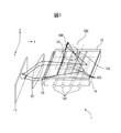
- FIG. 1 is a schematic configuration diagram of a display device according to the first embodiment of the present invention.
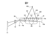
- FIG. 2 is a schematic side view of the display device according to the first embodiment of the present invention.
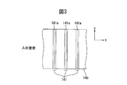
- FIG. 3 is a partially enlarged view of the diffusion surface as viewed from the front side.
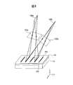
- FIG. 4 is a schematic perspective view of a light guide plate and a mask according to a modification.
- FIG. 5 is a schematic side view of a display device according to the second embodiment.
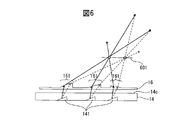
- FIG. 6 is a schematic side view of a light guide plate and a cylindrical lens according to a modification.
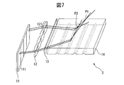
- FIG. 7 is a schematic configuration diagram of a display device according to a modification.
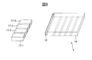
- FIG. 8 is a schematic configuration diagram of a display device according to another modification.
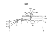
- FIG. 9 is a schematic side view of a display device according to still another modification.
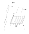
- FIG. 10 is a schematic configuration diagram of a display device according to still another modification.
- FIG. 11 is a schematic configuration diagram of a display device according to still another modification.
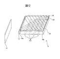
- FIG. 12 is a schematic configuration diagram of a display device according to still another modification.
- FIG. 13 is a schematic side cross-sectional view of the light guide plate along a direction orthogonal to the incident surface according to still another modification.
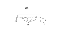
- FIG. 14 is a schematic side cross-sectional view of the light guide plate along a direction orthogonal to the incident surface according to still another modification.
- FIG. 15 is a diagram illustrating an example of an arrangement of an image display device, a light guide member, and a light guide plate according to still another modification.
- This display device has a plate-shaped light guide plate and an image display device arranged to face an incident surface formed on one side wall of the light guide plate. And between the image display device and the incident surface, an imaging lens for converging light from the image display device in a plane parallel to the output surface that is the surface of the light guide plate on the side facing the observer, A collimating lens for collimating the light from the image display device is disposed on the orthogonal plane.
- the image display device and the collimating lens constitute an image projection unit.
- a plurality of prisms are formed on the diffusion surface on the side opposite to the exit surface of the light guide plate to reflect the light from the image display device incident on the light guide plate toward the observer through the exit surface. Furthermore, between the exit surface and the observer, for each individual prism, only light from a position corresponding to that prism in a direction orthogonal to the exit surface on the display area of the image display device is directed to a specific viewpoint. A slit is provided for transmitting light. As a result, light emitted from individual points on the display area of the image display device is combined into one point in the direction parallel to the longitudinal direction of the incident surface by the imaging lens on the viewer side from the exit surface of the light guide plate.
- the observer can observe a projected image (real image) of the image displayed on the image display device as a set of imaging points corresponding to individual points on the display area. Moreover, since light spreads from the image forming point in a direction parallel to the longitudinal direction of the incident surface, parallax can be provided in that direction. Therefore, when the observer places his / her eyes so as to be parallel to the longitudinal direction of the incident surface, the observer can observe the projection image in three dimensions and move the viewpoint along that direction. The projected image can be observed.
- the side facing the observer is the front and the opposite side is the back.
- FIG. 1 is a schematic configuration diagram of a display device according to an embodiment of the present invention.
- FIG. 2 is a schematic side view of the display device.
- the display device 1 includes an image display device 11, an imaging lens 12, a collimator lens 13, a light guide plate 14, and a mask 15.
- the direction parallel to the longitudinal direction of the incident surface 14a of the light guide plate 14 is defined as the x direction
- the normal direction of the incident surface 14a is defined as the normal direction.
- the normal direction of the diffusing surface 14b and the exit surface 14c located on the front side of the light guide plate 14 is the z direction.
- the following drawings show an outline of the arrangement relationship of each component of the display device, and do not represent actual dimensions, the number of prisms, and the like.
- the image display device 11 is an example of an image display unit, and may be a liquid crystal display or an organic EL display, for example.
- the image display device 11 displays a two-dimensional image projected into the air by the display device 1 in a display area of the display surface of the display device 1 in accordance with a video signal received from a control device (not shown).
- the image display device 11 is arranged such that its display area faces the incident surface 14a of the light guide plate 14 and is substantially parallel to the incident surface 14a. This arrangement is an example, and the image display device 11 may be arranged to be inclined with respect to the incident surface 14a. In this case, the positional relationship with the imaging lens 12 changes for each position on the display area of the image display device 11. Then, the closer to the imaging lens 12 on the display area, the light emitted from that point forms an image at a position away from the light guide plate 14.
- the collimating lens 13 When the collimating lens 13 is arranged so that the center of the incident surface 14a coincides with the optical axis of the collimating lens 13 in the z direction, the collimating lens 13 extends along the z direction in a plane orthogonal to the optical axis. Light that has been emitted from each of two points that are equidistant across the optical axis and entered the light guide plate 14 via the incident surface 14a has the same angle with respect to the diffusion surface 14b. Therefore, the light from these two points is reflected by the same prism 141 and travels to the viewpoint. Therefore, these two points appear to overlap with the observer.
- the image display device 11 is preferably arranged so that the entire display region is located on the front side or the back side of the light guide plate 14 in the z direction.
- the entire display area of the image display device 11 is disposed on the back side of the light guide plate 14.
- the light of the collimator lens 13 in the z direction as shown by the dotted line in FIG. It is preferable to dispose a mirror 20 that is disposed on the opposite side of the image display device 11 across the axis and that has a reflection surface parallel to the emission surface 14c and directed toward the image display device 11.
- the imaging lens 12 is an example of an imaging unit, and is a cylindrical lens having positive power in the xy plane and no power in the yz plane, and the incident surface 14 a of the image display device 11 and the light guide plate 14.
- the optical axis is arranged so as to be parallel to the normal line of the incident surface 14a.
- the imaging lens 12 may be a bulk lens, or may be a Fresnel lens or a diffractive lens in order to reduce the thickness.
- the imaging lens 12 may be a single lens, or may include a plurality of lenses arranged along the y direction in order to correct aberrations. Further, at least one lens surface of the imaging lens 12 may be formed as an aspheric surface in the xy plane in order to correct aberration.
- the imaging lens 12 converges light emitted from individual points (pixels) on the display area of the image display device 11 in the xy plane, and, as will be described later, the light exit surface 14c of the light guide plate 14 and the observer's An image is formed at a predetermined position.
- the collimating lens 13 is disposed between the image display device 11 and the incident surface 14 a of the light guide plate 14. In this embodiment, the collimating lens 13 is disposed between the imaging lens 12 and the incident surface 14a. However, the collimating lens 13 may be disposed between the image display device 11 and the imaging lens 12. . In the present embodiment, the collimating lens 13 is arranged so that its optical axis is parallel to the normal line of the incident surface 14a.
- the collimating lens 13 is configured as a cylindrical lens having positive power in the yz plane and no power in the xy plane.
- the collimating lens 13 may be a bulk lens or a Fresnel lens, like the imaging lens 12.
- the collimating lens 13 may be a single lens or may include a plurality of lenses disposed along the y direction. Furthermore, at least one lens surface of the collimating lens 13 may be formed as an aspheric surface even in the yz plane.
- the imaging lens 12 and the collimating lens 13 may be constituted by a single lens.
- one surface of the lens is formed to have a positive power only in the xy plane, and the other surface of the lens is formed to have a positive power only in the yz plane.
- the collimating lens 13 may be formed integrally with the incident surface 14a. That is, the incident surface 14a may be formed as a cylindrical lens.
- the light guide plate 14 directs the light emitted from the image display device 11 toward the observer. Therefore, the light guide plate 14 is a transparent member formed in a flat plate shape, and the side wall facing the image display device 11 is formed as the incident surface 14a.
- the light that has entered the light guide plate 14 from the incident surface 14a is the diffusion surface 14b that is the back surface of the light guide plate 14 and the front surface of the light guide plate 14, that is, the surface that faces the diffusion surface 14b. It propagates along the y direction while being totally reflected between the exit surface 14c.
- a plurality of prisms 141 that reflect the light incident on the light guide plate 14 through the incident surface 14a so as to be emitted toward the viewer side through the output surface 14c are provided on the diffusion surface 14b of the light guide plate 14. It is formed.
- Each prism 141 is an example of a deflecting unit. As will be described in detail later, the light emitted from the image display device 11 and propagating through the light guide plate 14 is directed to a specific viewpoint by the slits 151 formed in each prism 141 and the mask 15.
- FIG. 3 is a partially enlarged view of the diffusing surface 14b as seen from the front side.
- the plurality of prisms 141 are arranged in a lattice shape at a predetermined pitch (for example, 1 mm) along the y direction.
- Each of the plurality of prisms 141 is, for example, a substantially triangular groove that extends along the x direction, that is, a direction substantially parallel to the longitudinal direction of the incident surface 14a, and has a predetermined width (for example, 10 ⁇ m) in the y direction.
- Each of the plurality of prisms 141 has a reflecting surface 141a that forms a predetermined angle ⁇ with respect to the diffusing surface 14b and is directed to face the incident surface 14a.
- the predetermined angle ⁇ is an angle at which the light from the image display device 11 incident on the light guide plate 14 is totally reflected and directed toward the emission surface 14c, for example, 37 to 45 ° with respect to the diffusion surface 14b. Is set.
- each prism 141 is formed such that the angle ⁇ is the same for each prism 141.
- each prism 141 Since each prism 141 is formed as described above, the light emitted from the image display device 11 and entering the light guide plate 14 becomes convergent light in the xy plane by the imaging lens 12, By being reflected by the prism 141, this time, it becomes convergent light in the xz plane. Further, since the light is collimated in the yz plane by the collimator lens 13, the angle according to the position in the z direction on the display area of the image display device 11 is set to the reflecting surface 141 a of the prism 141 in the yz plane. Will do. Therefore, on the yz plane, light emitted from individual points on the display area of the image display device 11 is emitted in different directions depending on the position of the point in the z direction.
- the imaging lens 12, the collimating lens 13, and the light guide plate 14 are formed by molding a material that is transparent to visible light, for example, a resin such as polymethyl methacrylate (PMMA), polycarbonate, or cycloolefin polymer. It is formed.
- a resin such as polymethyl methacrylate (PMMA), polycarbonate, or cycloolefin polymer. It is formed.
- the mask 15 is a sheet-like member formed of a material that is opaque to visible light, and is disposed on the front side of the light exit surface 14 c of the light guide plate 14.
- a plurality of slits 151 parallel to the x direction are arranged along the y direction. Each slit 151 corresponds to one of the prisms 141.
- each of the slits 151 is a specific part of the light emitted from the image display device 11 and propagating through the light guide plate 14 and reflected by the corresponding prism 141. It is provided at a position where only light traveling toward the viewpoint 100 is transmitted and other light is blocked. Therefore, in this example, the light emitted from the image display device 11 is collimated by the collimating lens 13 with respect to the yz plane, and therefore is transmitted according to the position in the z direction on the display area of the image display device 11.
- the slit 151 is different. For example, in the example shown in FIG.
- the light emitted from a point located on the back side on the display area of the image display device 11 passes through the slit 151 closer to the incident surface 14 a and travels toward the viewpoint 100.
- the present invention is not limited to this, and the position in the z direction on the display area of the image display device 11 and the set of the prism 141 and the slit 151 need only correspond one to one.
- the viewpoint 100 is a linear range along the x axis, and light emitted from individual points in the display area of the image display device 11 is coupled by the imaging lens 12. It is set farther from the image forming point 101 to be imaged. Therefore, when viewed from the viewpoint 100, the real image of the image displayed in the display area is projected onto the plane 102 where the imaging points 101 corresponding to the individual points in the display area of the image display device 11 are gathered. An observer who observes from the viewpoint 100 can observe a real image projected on the plane 102.
- the display device 1 can widen the range in which an image projected in the air can be visually recognized.
- this display device emits light from individual points in the display area of the image display device and is emitted from the light guide plate as convergent light in a direction parallel to the longitudinal direction of the incident surface. After that, an image is formed at a predetermined position.
- the surface in the direction orthogonal to the longitudinal direction of the incident surface is converted into parallel light, and the angle when exiting from the light guide plate is set to the position of that point in the direction orthogonal to the longitudinal direction of the incident surface.
- the light in the direction toward the specific viewpoint located on the front side of the light guide plate is changed in accordance with the slit provided in the mask so that the position of light emission from the light guide plate and the light emission direction correspond to each other one to one.
- the display device allows the user to visually recognize the image displayed on the image display device and projected in the air when viewed from the viewpoint. Furthermore, this display device seems to spread light from the imaging position on the surface in the direction of the convergent light with respect to the light emitted from the individual points in the display area of the image display device, and thus along the direction. By arranging both eyes side by side, the observer can observe the projected image three-dimensionally, and can visually recognize the projected image even if the viewpoint is changed along that direction.
- FIG. 4 is a schematic perspective view of a light guide plate and a mask according to a modification.
- the light transmitted through the slit 151 is diffused to each slit 151 of the mask 15 on the yz plane, that is, the plane including the light propagation direction in the light guide plate 14 and the normal line of the exit surface 14c.
- a diffusion member 152 is provided.
- the diffusing member 152 can be, for example, a diffraction grating formed at a predetermined pitch along the y direction, or a cylindrical concave lens having negative power in the y direction.
- the mask 15 can widen the range in which the observer can see the image projected in the air also in the y direction while giving parallax in the x direction.
- the observer when both eyes are arranged along the viewpoint 100a parallel to the x direction, the observer can stereoscopically observe the image projected on the plane 102a.
- the observer when both eyes are arranged along the viewpoint 100b parallel to the x direction at a position shifted in the y direction from the viewpoint 100a, the observer can view the image projected on the plane 102b in a three-dimensional manner. Can be observed.
- the position where the projected image can be seen when the observer shifts the position of the eye along the y direction, the position where the projected image can be seen also changes along with the shift of the viewpoint.
- the position where the projected image can be seen does not change.
- FIG. 5 is a schematic side view of the display device 2 according to the second embodiment.
- the display device 2 according to the second embodiment includes an image display device 11, an imaging lens 12, a collimator lens 13, and a light guide plate 14.
- the display device 2 according to the second embodiment is different from the display device 1 according to the first embodiment in the configuration of prisms provided on the light guide plate 14 instead of omitting the mask 15. Therefore, the above differences will be described below.
- For other components of the display device 2 refer to the description of the corresponding components of the display device 1 according to the first embodiment.
- the angle ⁇ formed between the reflecting surface of each prism 141 and the diffusing surface 14b is set to increase as the distance from the incident surface 14a increases.
- the angle ⁇ is preferably set so that even the prism 141 farthest from the incident surface 14a is an angle at which the light from the image display device 11 can be totally reflected.
- the angle ⁇ of the reflecting surface for each prism 141 is set. Therefore, in the second embodiment, the position in the z direction on the display area of the image display device 11 starts from the point on the back side and is predetermined.
- the light traveling toward the viewpoint (for example, the viewpoint 500a or the viewpoint 500b) is reflected by the prism 141 far from the incident surface 14a.
- the present invention is not limited to this, and the position in the z direction on the display area of the image display device 11 and the prism 141 need only correspond one to one.
- the display device 2 can emit light from the image display device 11 toward a specific viewpoint.
- the light emitted from the light guide plate 14 forms an image on the surface on which the image is projected in the x direction, and diffuses as the distance from the surface increases. Therefore, the display device 2 can give a parallax with respect to the x direction, so that the projected image can be stereoscopically observed when the observer arranges both eyes along the x direction.
- each prism 141 and directed toward the viewpoint since light reflected by each prism 141 and directed toward the viewpoint is not blocked, the observer is displayed on the image display device 11 even if the observer moves the viewpoint along the y direction. In addition, an image projected in the air can be observed.
- the angle formed between the light beam traveling from each prism 141 toward the viewpoint and the reflecting surface of each prism 141 changes along the position of the viewpoint in the y direction. Accordingly, on the image display device 11 corresponding to the light beam. The position of the point also changes.
- light from the respective points 501a to 501c on the image display device 11 are prisms 141-1 to 141-1, respectively.
- 141-4 (however, the prisms 141-1, 141-2, 141-3, and 141-4 are arranged in order of increasing distance from the incident surface 14a) and are reflected by the prisms 141-1 to 141-3 and projected onto the projection surface 502a.
- the observer moves the eye to the viewpoint 500b that is further from the incident surface 14a than the viewpoint 500a.
- the light emitted from the light guide plate 14 is observed from the viewpoint 500b toward the direction away from the incident surface 14a than the viewpoint 500a.
- the angle ⁇ formed between the reflecting surface of each prism 141 and the diffusing surface 14b is set to increase as the distance from the incident surface 14a increases.
- each point 501a on the image display device 11 is set.
- the light from ⁇ 501c is reflected by the prisms 141-2 to 141-4 closer to the incident surface 14a side, forms an image on the projection surface 502b, and then travels toward the viewpoint 500b. Therefore, even if the observer changes the viewpoint along the y direction, the position of the projected image does not shift much.
- light from each point on the image display device 11 is imaged to some extent in the y direction by each prism 141. Therefore, the observer can observe a stereoscopic image even if both eyes are arranged along the y direction.
- the display apparatus 2 can make an observer visually recognize both the object (not shown) behind the light guide plate 14 and the projected image.
- the arrangement density which is the ratio of the area of the area where the prism 141 is formed to the area of the diffusing surface 14b, is determined by the observer using an object (not shown) behind the light guide plate 14 as a transparent member. It is preferable that it becomes below the upper limit of the arrangement density felt that it is visually recognizing through the space or nothing. Therefore, for example, the prisms 141 are preferably arranged so that the arrangement density is 30.0% or less.
- the haze value indicating the ratio of the diffused light to the total transmitted light is determined by an observer through an object (not shown) behind the light guide plate 14 through a transparent member or whatever It is preferable that it becomes below the upper limit of the haze value felt to be visually recognizing through the empty space.
- each prism 141 is preferably arranged so that the haze value is 28% or less.
- each prism 141 provided on the diffusing surface 14b of the light guide plate 14 is formed so as to be discrete in the longitudinal direction (that is, the x direction) of the incident surface 14a. Also good. In this case, each prism 141 may be arranged in a square lattice shape, or may be arranged in a staggered pattern.
- a cylindrical lens having power in the yz plane at a position where the light reflected by the prism 141 and the light emitted from the emission surface 14c passes for each prism 141 at a position facing the emission surface 14c. May be arranged.
- FIG. 6 is a schematic side view of a light guide plate and a cylindrical lens according to this modification.
- a prism sheet 16 formed of a transparent member is disposed so as to face the light exit surface 14 c of the light guide plate 14.
- the prism 161 is provided with a prism 161 at a position where light from the image display device 11 that is reflected by the prism 141 and is emitted from the emission surface 14c is transmitted.
- the light guide plate 14 light from each point on the image display device 11 propagates in a direction corresponding to the position in the z direction of the point.
- each prism 141 so as to be emitted from the emission surface 14c in different directions in the yz plane according to the position of the point in the z direction. Therefore, the light from each point on the image display device 11 has a different position in the y direction when passing through the prism 161 according to the position in the z direction of the point. Therefore, by appropriately setting the direction of the refractive surface of each prism 161 on the yz plane according to the position in the y direction, the light from any point on the image display device 11 is reflected by which prism 141. However, it passes through the same position on the projection plane 601.
- this display device can keep the position of the projected image constant even when the observer changes the position of the viewpoint along the y direction. That is, in this modification, the display device can correct the position at which the light from the image display device 11 is projected for each prism 141.
- the direction in the yz plane of the light emitted from the light guide plate 14 can be adjusted by the prisms 161 provided on the prism sheet 16, so that the reflection of each prism 141 formed on the light guide plate 14 is reflected.
- the angle formed by the surface and the diffusion surface may be the same.
- an object for display may be placed instead of the image display device 11.
- the display device since the position on which the point on the object is projected changes according to the positional relationship between each point on the object and the imaging lens 12, the display device displays a three-dimensional image of the object. Can be projected in the air.
- the imaging lens 12 may be configured as a lens array.
- FIG. 7 is a schematic configuration diagram of a display device according to this modification.
- the display device 3 shown in FIG. 7 is a lens array in which the imaging lens 12 includes a plurality of cylindrical lenses 121 arranged in a line along the x direction, compared to the display device 2 according to the second embodiment. It differs in that it is configured. Therefore, the difference will be described below.
- the individual cylindrical lenses 121 constituting the lens array are referred to as sub-cylindrical lenses.
- the imaging lens 12 can be reduced in size, and only light that passes through a portion close to the optical axis can be obtained as compared with the case where one cylindrical lens is used. Since this is used, the aberration is reduced.
- the display area of the image display device 11 is divided into a plurality of partial areas 111 corresponding to the individual sub-cylindrical lenses 121 along the x direction. Displays an image viewed from the same direction.
- each partial area 111 by adjusting the position of the image displayed in each partial area 111, light from the same point on the image displayed in each partial area 111 is imaged at a specific point in the air. .
- an image is displayed in each partial area 111 so that the same point on the image is located at a position where a ray passing through the point P1 in the air and the principal point of each sub-cylindrical lens 121 intersects each partial area 111. It only has to be done. That is, as the image is projected closer to the light guide plate 14, the image position in each partial region 111 may be displayed so as to be separated along the x direction with respect to the center of the light guide plate 14 in the x direction. Therefore, the display device according to this modified example adjusts the position of the image displayed in each partial region 111, so that the same point on the image is gathered at one point, that is, the position where the image is projected. Can be changed.
- this display device can display an image in a three-dimensional manner by changing the position where the light from the corresponding point of each partial region 111 gathers at one point in the air for each point in the image. For example, for the first point on the image, a light ray passing through the point P1 in the air and the principal point of each sub-cylindrical lens 121 is displayed at a position where each partial region 111 intersects, and the second point on the image With regard to, it is only necessary that the light ray passing through the air point P2 and the principal point of each sub-cylindrical lens 121 is displayed at a position where it intersects with each partial region 111. That is, each partial area 111 displays an image of the same subject viewed from different directions. Thereby, the observer looks like the first point is located at the point P1, and the second point appears to be located at the point P2.
- the projected image becomes blurred as the relationship between each partial region 111 and the position at which the image displayed on each partial region 111 is projected deviates from the positional relationship that is the imaging relationship by the sub-cylindrical lens 121. Therefore, it is preferable to adjust the position where the blur is projected within an allowable range.
- another image may be displayed for each partial region 111.
- the power of the sub-cylindrical lens 121 may be different for each image display device.
- the position at which the image displayed in the partial area 111 is imaged changes for each partial area 111. Therefore, the display device can project an image at a different position for each partial region 111, and thus a three-dimensional image display is possible.
- the individual sub cylindrical lenses are formed independently of each other, the position of the sub cylindrical lens in the y direction may be changed for each partial region 111.
- a different image display device may be used for each partial region 111.
- each sub-cylindrical lens in the y direction is the same, and instead, the position in the direction of the image display device may be changed for each image display device. Also in this case, the position at which the image displayed on the image display device is imaged changes for each image display device according to the positional relationship between the image display device and the sub-cylindrical lens. Images can be projected at different positions for each device.
- one sub-cylindrical lens set corresponding to one image display device can be replaced with one projector.
- FIG. 8 is a schematic configuration diagram of a display device according to this modification.
- Each of the plurality of projectors 17-1 to 17-n includes a display (not shown) for displaying an image to be projected, and a projection optical system (not shown) for projecting the image displayed on the display.
- the plurality of projectors 17-1 to 17-n are other examples of the image display unit and the imaging unit, respectively.
- the display device 4 as in the display device 3, the same images are displayed on the projectors 17-1 to 17-n. Thereby, the display device 4 can obtain the same effect as the display device 3.
- the projection optical system of the projector is normally formed rotationally symmetric about the optical axis of the projection optical system, so that not only the xy plane but also the yz plane, that is, the normal line of the exit surface 14c of the light guide plate 14 is used. And a plane including the normal of the incident surface 14a also has a positive power. Therefore, in this modification, the collimating lens 13 is the entire optical system including the projection optical system of each projector 17-1 to 17-n and the collimating lens 13, and the display of each projector 17-1 to 17-n with respect to the yz plane. It is preferably formed as a cylindrical lens having a power such that light from the individual points above becomes parallel light. Such power is determined based on the positional relationship between the projection optical system and the collimating lens 13 and the power of the projection optical system.
- an image is projected according to the position in the y direction of the display area of the image display device by disposing the microlens array on the front side of the light exit surface 14c of the light guide plate 14.
- the positions may be different.
- FIG. 9 is a schematic side view of a display device according to this modification.
- the display device 5 is different from the display device 2 in that the display device 5 includes a microlens array 18 disposed on the front side of the light exit surface 14c of the light guide plate 14. Therefore, this difference will be described below.
- the angle at which light emitted from that point propagates in the light guide plate 14 changes. Therefore, the direction of light emitted from the emission surface 14c on the yz plane also changes according to the position in the z direction of each point on the display area of the image display device 11. As a result, as shown by lines 901 to 903, even on the viewer side of the exit surface 14 c, even the light reflected by the same prism 141, the individual light on the display area of the image display device 11 from which the light is emitted. Depending on the position of the point in the y direction, the position in the y direction will be different.
- microlens array 18 for each individual prism 141 of the light guide plate 14, a plurality of microlenses 181 are provided along the y direction in a range where light reflected by the prism 141 and emitted from the emission surface 14c passes. It is done.
- Each microlens 181 corresponds to one of the partial areas 112 obtained by dividing the display area of the image display device 11 into a plurality along the z direction.
- the microlens 181 closer to the incident surface 14a corresponds to the partial region 112 located on the back side.
- Each microlens 181 is formed, for example, as a cylindrical lens having a cylindrical side refractive surface that extends along the x direction so as to have power in the yz plane and not in the xy plane. Is done.
- the display area of the image display device 11 is divided into three partial areas 112 along the z direction. Therefore, the microlens array 18 has three microlenses 181 arranged along the y direction with respect to one prism 141.
- the display device 5 can change the projection position of the image displayed in the partial area 112 for each partial area 112. Therefore, the display device 5 can display a stereoscopic image.
- each microlens 181 may have a different prism component depending on the corresponding partial region 112. That is, the optical axis of each microlens 181 may be tilted according to the relationship between the direction when the light emitted from the corresponding partial region 112 exits the light guide plate 14 and the projection position. Since the direction in which the light emitted from the point in the partial region 112 is refracted by the microlens 181 is different for each partial region 112 depending on the prism component of each microlens 181, the display device 5 is different for each partial region 112. The orientation of the projected image, particularly the tilt of the projected image relative to the y direction in the yz plane can be adjusted.
- a prism itself may be used. That is, a microprism array may be used instead of the microlens array.
- the orientation of the refractive surface of the prism corresponding to each partial area 112 is adjusted to be different for each partial area 112 according to the position of the corresponding projected image in each partial area 112. Also in this case, the display device 5 can adjust the direction of the projected image for each partial region 112.
- each prism provided on the light guide plate 14 may be formed to have power in the xy plane instead of the imaging lens 12.
- FIG. 10 is a schematic configuration diagram of a display device according to this modification.
- the imaging lens 12 is omitted and each prism 142 provided on the diffusion surface 14b of the light guide plate 14 is formed as a concave mirror in the xy plane as compared with the display device 2. Is different. Therefore, this difference will be described below.
- Each prism 142 is formed in an arc shape so as to be concave with respect to the incident surface 14a with respect to the xy plane. Therefore, each prism 141 becomes a concave mirror having positive power with respect to the xy plane. Therefore, even if the imaging lens 12 is omitted, the light emitted from each point on the display area of the image display device 11 and entering the light guide plate 14 is reflected by any prism 142 and is emitted from the exit surface 14c. Will also form an image on the viewer side. Therefore, the display device 6 can also project the image displayed in the display area of the image display device 11 in the air, like the display device 2.
- each prism 142 is set according to the position where the image displayed on the image display device 11 is projected. For example, as shown in the projected image 1001, when an image displayed on the image display device 11 arranged along the xz plane is projected so as to be substantially parallel to the exit surface 14c of the light guide plate 14, the incident surface The prism 142 farther from 14a is formed to have a smaller radius of curvature. Moreover, each prism 142 should just be formed so that the center of each prism 142 may be located on the centerline of the light-guide plate 14 in x direction, for example.
- the display device 6 projects an image so as to be closer to the incident surface 14a side than the front side of the light guide plate 14 and to form a predetermined angle with respect to the emission surface 14c. be able to.
- the angle formed by the reflecting surface of each prism 142 and the diffusing surface 14b of the light guide plate 14 is set so as to increase as the distance from the incident surface 14a increases. Therefore, the observer can observe the image displayed on the image display device 11 projected into the air by the light guide plate 14 from a predetermined viewpoint.
- the display device can be reduced in size.
- each prism 142 may be formed as a retroreflective element instead of being formed as a concave mirror.
- FIG. 11 is a schematic configuration diagram of a display device according to this modification.
- the display device 7 shown in FIG. 11 is different from the display device 6 in the shape of each prism 143 provided on the diffusion surface 14 b of the light guide plate 14. Therefore, this difference will be described below.
- each prism 143 has a shape in which a plurality of corner mirrors 143b retroreflected in the xy plane are arranged along the x direction. Therefore, the light emitted from each point in the display area of the image display device 11 and entering the light guide plate 14 is returned to the original direction by the respective corner mirrors 143b of any one of the prisms 143 with respect to the component parallel to the xy plane. Retroreflected back. Therefore, in this embodiment, as shown as the projected image 1101, the image displayed on the image display device 11 is projected at substantially the same position as the image display device 11 in the y direction.
- the angle formed by the reflecting surface of each prism 143 and the diffusing surface 14b of the light guide plate 14 is set so as to increase as the distance from the incident surface 14a increases. Therefore, the observer can observe the image displayed on the image display device 11 projected into the air by the light guide plate 14 from the viewpoint on the image display device 11 side with respect to the incident surface 14a.
- FIG. 12 is a schematic configuration diagram of a display device according to this modification.
- the display device 8 illustrated in FIG. 12 includes a corner reflector plate 19 disposed on the front side of the light exit surface 14c of the light guide plate 14 instead of omitting the imaging lens 12. It is different in having. Therefore, this difference will be described below.
- the corner reflector plate 19 is an example of a retroreflective portion, and has a plurality of corner reflectors 191 arranged in an array. Each corner reflector 191 retroreflects the incident light with respect to the xy plane. Therefore, in the display device 8, the light emitted from the image display device 11 and entering the light guide plate 14 is reflected by any prism 141 and emitted from the emission surface 14 c, and then incident by any corner reflector 191. Retroreflected toward the surface 14a. Therefore, in the display device 8, as with the display device 7, the image displayed on the image display device 11 is projected at substantially the same position as the image display device 11 in the y direction. Even when the corner reflector plate 19 is used, an imaging lens that converges light from the image display device 11 on the xy plane may be disposed between the image display device 11 and the light guide plate 14.
- the light guide plate 14 may cause the light propagating inside the light guide plate 14 to be emitted from the emission surface 14c by means other than the prism.
- FIG. 13 is a schematic side sectional view of the light guide plate 14 along the y direction according to this modification.
- the light guide plate 14 has a plurality of prisms 144 arranged at a predetermined pitch along the y direction on the exit surface 14c instead of the prisms formed on the diffusion surface 14b.
- each prism 144 is formed as a substantially triangular protrusion that protrudes frontward with respect to the emission surface 14c and extends along the x direction. Therefore, when the light from the image display device 11 that has entered from the incident surface 14a enters one of the prisms 144, the light is refracted on the refractive surface opposite to the incident surface 14a and is emitted to the front side.
- the angle formed between the refracting surface of each prism 144 and the exit surface 14c of the light guide plate 14 is set to increase as the distance from the entrance surface 14a increases. Therefore, the observer can observe the image displayed on the image display device 11 projected into the air by the light guide plate 14 from a predetermined viewpoint.
- the light guide plate 14 emits the light in the reflection direction at a predetermined pitch along the y direction on the diffusion surface 14b without being totally reflected by the emission surface 14c, instead of each prism.
- a diffraction grating for changing the direction may be formed.
- each diffraction grating has, for example, a plurality of grooves arranged along the y direction and extended along the x direction.
- the pitch between grooves should just be set according to the direction which reflects light. Accordingly, the pitch between the grooves of each diffraction grating is set so that the diffraction grating closer to the incident surface 14a reflects light toward the far side from the incident surface 14a. Can observe an image displayed on the image display device 11 and projected in the air from a predetermined viewpoint.
- the light guide plate 14 may be formed in a wedge shape such that the thickness in the z direction decreases as the distance from the incident surface 14a increases along the y direction.
- FIG. 14 is a schematic side cross-sectional view of the light guide plate 14 along the y direction according to this modification.
- the light guide plate 14 is formed such that the thickness in the z direction decreases as the distance from the incident surface 14a increases, and the diffusion surface 14b approaches the front side as the distance from the incident surface 14a increases.
- the light plate 14 is disposed.
- the light incident from the incident surface 14a propagates through the wedge-shaped light guide plate 14, and thus the reflection angle with respect to the output surface 14c gradually increases, so that the light is reflected by the prism 141 far from the incident surface 14a.
- the display device can emit light toward the far side from the incident surface 14a by the refractive index at the output surface 14c, and therefore, as shown in the projection image 1001, the incident surface 14a.
- the image displayed on the image display device 11 can be projected on the opposite side and at a relatively large angle (for example, 60 to 90 °) with respect to the emission surface 14c.
- the incident surface may be formed so that the angle formed by the incident surface and the exit surface of the light guide plate is other than an orthogonal angle.
- the incident surface may be formed in a tapered shape.
- the incident surface may be formed to be parallel to the emission surface or the diffusion surface, and the surface of the light guide plate on the side facing the incidence surface may be formed to form 45 ° with respect to the emission surface or the diffusion surface. Good. Thereby, the angle formed by the image display device and the light exit surface of the light guide plate can be reduced, so that the display device can be thinned.
- a light guide member that guides light from the image display device 11 toward the light guide plate 14 may be used instead of the collimating lens 13.
- FIG. 15 is a diagram illustrating an example of the arrangement of the image display device, the light guide member, and the light guide plate according to this modification.
- light emitted from the image display device 11 reaches the incident surface 14a of the light guide plate 14 via the collimator lens 131 and the light guide member 132, and the light is on the image display device 11 in the yz plane.
- the collimating lens 131 and the light guide member 132 are arranged so as to be parallel light having an angle corresponding to the position of FIG.
- the collimating lens 131 and the light guide member 132 are other examples of the collimating member.
- the collimating lens 131 and the light guide member 132 together with the image display device 11 constitute an image projection unit.
- the light guide member 132 is a transparent member formed in a rectangular parallelepiped shape, and one surface in the short direction is formed as the incident surface 132a.
- one surface along the longitudinal direction of the light guide member 132 is formed as an emission surface 132c that emits light incident from the incident surface 132a, and a surface facing the emission surface 132c is formed as a diffusion surface 132b.
- the length of the light guide member 132 in the longitudinal direction is substantially equal to the length of the incident surface 14a in the longitudinal direction, and the thickness of the light guide member 132 in the yz plane is larger than the thickness of the light guide plate 14 in the yz plane.
- the light guide member 132 is preferably formed to be thick. Thereby, the light guide member 132 can guide the light from the image display device 11 to the light guide plate 14 while maintaining the angle of light according to the position in the z direction on the display surface of the image display device 11.
- the light guide member 132 is disposed so that the light exit surface 132 c of the light guide member 132 faces the incident surface 14 a of the light guide plate 14.
- the image display device 11 is disposed so as to face the incident surface 132 a of the light guide member 132 through the collimator lens 131 and to be positioned at the front focal point of the collimator lens 131. That is, in this example, the image display device 11 is disposed so that the display surface of the image display device 11 is parallel to the direction orthogonal to the incident surface 14 a of the light guide plate 14. Therefore, in this modification, the image display device can be reduced in size, and the entire display device is also reduced in size.
- the incident surface may be formed so as to have a taper shape, for example, so that the angle formed by the incident surface and the output surface of the light guide member is not an orthogonal angle.
- the light guide member 132 and the light guide plate 14 may be integrally formed.
- the light emitted from the image display device 11 is collimated by the collimator lens 131 regardless of the direction, and enters the light guide member 132 from the incident surface 132a of the light guide member 132. That is, the light emitted from the image display device 11 becomes parallel light directed in the direction corresponding to the display position on the image display device 11.
- the collimated light propagates through the light guide member 132 while being totally reflected, and is reflected toward the emission surface 132 c by the plurality of prisms 133 provided on the diffusion surface 132 b of the light guide member 132.
- the prisms 133 are arranged in a grid at a predetermined pitch (for example, 1 mm) along the x direction, that is, the longitudinal direction of the incident surface 14a of the light guide plate 14.
- Each prism 133 is formed, for example, as a substantially triangular groove that extends along the z direction and has a predetermined width (for example, 10 ⁇ m) in the x direction.
- Each prism 133 has a reflecting surface that forms a predetermined angle ⁇ with respect to the diffusing surface 132b and is directed to face the incident surface 132a.
- the predetermined angle ⁇ is an angle at which the light from the image display device 11 incident on the light guide member 132 is totally reflected and directed toward the emission surface 132c, for example, 37 to 45 ° with respect to the diffusion surface 132b.
- each prism 133 is formed such that the angle ⁇ increases toward the prism 133 farther from the incident surface 132a so that light directed in the same direction on the xy plane is condensed at one point on a predetermined imaging plane. .
- the light emitted from the light guide member 132 is parallelized in the short direction (that is, the thickness direction) of the incident surface 14a of the light guide plate 14, while the incident surface 14a. The light is converged in the longitudinal direction. Therefore, like the display devices according to the above embodiments, the display device can spatially project the image displayed on the image display device 11.
- the collimating lens 131 and the light guide member 132 are each formed by molding a material transparent to visible light, for example, a resin such as polymethyl methacrylate (PMMA), polycarbonate, or cycloolefin polymer.
- a resin such as polymethyl methacrylate (PMMA), polycarbonate, or cycloolefin polymer.
- a cylindrical lens having a positive power in the longitudinal direction of the incident surface 14 a may be disposed between the exit surface 132 c of the light guide member 132 and the incident surface 14 a of the light guide plate 14.
- the angles of the reflecting surfaces of the prisms 133 of the light guide member 132 are the same. Also good.
- each prism of the light guide plate 14 is formed in a concave mirror shape, or as shown in FIG.
- each prism of the light guide plate 14 is formed in a corner mirror shape,
- the angles of the reflecting surfaces of the prisms 133 of the light guide member 132 may be the same.
- the thickness between the diffusing surface 132b and the exit surface 132c of the light guide member 132 has a wedge shape that decreases as the distance from the incident surface 132a increases.
- the light guide member 132 may be formed.
- the light guide member 132 may be arrange
- each prism may be formed on the emission surface 132c side.
- a projected image is represented instead of the image display device 11 and the collimator lens 13 (or the collimator lens 131 and the light guide member 132).
- a hologram sheet having a display surface on which a hologram is displayed in a predetermined area may be used.
- the hologram sheet may be disposed so as to face the incident surface 14a of the light guide plate 14 with the imaging lens 12 interposed therebetween.
- the hologram sheet can generate parallel light having different directions for each position of the projected image. Accordingly, in this case as well, the display device can project an image onto the space as in the above embodiments.
- the image display device 11 may be disposed closer to the imaging lens 12 than the focal point of the imaging lens 12.
- the observer can observe a virtual image of the image displayed in the display area of the image display device 11 that appears to be located on the back side of the light guide plate 14.
- the imaging lens 12 is a concave lens. Also good.
- the image display device 11 may appear to be located on the back side of the light guide plate 14, and the imaging lens 12 may be omitted to display a virtual image of the image displayed in the display area of the image display device 11. Good.
- a value obtained by dividing the product by the product of the cosine of the angle between and the image is displayed at a position away from the incident surface 14 a of the light guide plate 14 by a distance corresponding to a value obtained by subtracting the distance between the virtual image and the light guide plate 14.
- the device 11 may be arranged.
- the position of each slit 151 in the direction orthogonal to the entrance plane 14a should just be determined according to the position of the virtual image displayed.
- each prism is determined according to the position of the virtual image to be displayed.
- the angle ⁇ of the reflecting surface 141 may be set. That is, as the prism 141 is farther from the incident surface 14a, the angle ⁇ of the reflecting surface of the prism 141 becomes smaller.
- the display device may include a plurality of image display devices 11. And each image display apparatus 11 is installed in a mutually different position, for example.
- each image display device 11 may be installed such that the directions of the image display devices 11 with respect to the incident surface 14a of the light guide plate 14 are different from each other.
- Each image display device 11 may display the same image or may display different images. Thereby, the image displayed on each image display apparatus 11 is projected on a mutually different position. Therefore, the display device can project a plurality of different images at different positions at the same time.
- the light guide plate 14 may be formed in a plate shape such that the emission surface 14c is a curved surface instead of a flat plate shape. Accordingly, for example, the light guide plate 14 can be disposed along a curved member, such as a windshield of a vehicle, and the degree of freedom in disposing the display device is improved.
- This display device can be used for various purposes.
- the display device can be used for a head-up display or a digital signage system.
- this display device may be arranged such that the exit surface of the light guide plate is located on the floor surface, the wall surface, or the ceiling surface.
Landscapes
- Physics & Mathematics (AREA)
- General Physics & Mathematics (AREA)
- Optics & Photonics (AREA)
- Light Guides In General And Applications Therefor (AREA)
Abstract
Description
なお、以下では、説明の便宜上、観察者と対向する側を正面とし、その反対側を背面とする。
またこの場合、画像表示装置11からコリメートレンズ13を経由して導光板14内に入射する光の量を増やすために、図2において点線で示されるように、z方向について、コリメートレンズ13の光軸を挟んで画像表示装置11とは反対側に配置され、かつ、出射面14cと平行かつ画像表示装置11へ向けられた反射面を持つミラー20を配置することが好ましい。
第2の実施形態による表示装置2は、第1の実施形態による表示装置1と比較して、マスク15が省略される代わりに、導光板14に設けられるプリズムの構成が相違する。そこで以下では、上記の相違点について説明する。表示装置2の他の構成要素に関しては、第1の実施形態による表示装置1の対応する構成要素の説明を参照されたい。
なお、この変形例では、プリズムシート16に設けられた各プリズム161により、導光板14から出射した光のyz平面内での向きを調節できるので、導光板14に形成される各プリズム141の反射面と拡散面のなす角は、同一であってもよい。
なお、この例でも、各プリズム144の屈折面と導光板14の出射面14cとのなす角は、入射面14aから離れるほど大きくなるように設定される。そのため、観察者は、所定の視点から、導光板14により空中に投影される、画像表示装置11に表示された画像を観察できる。
この変形例では、画像表示装置11から発した光が、コリメートレンズ131及び導光部材132を介して導光板14の入射面14aへ達し、かつ、その光は、yz平面では画像表示装置11上の位置に応じた角度を持つ平行光となり、xy平面でも平行光となるように、コリメートレンズ131及び導光部材132が配置される。なお、コリメートレンズ131及び導光部材132は、コリメート部材の他の一例である。また、コリメートレンズ131及び導光部材132は、画像表示装置11とともに、画像投影部を構成する。
11 画像表示装置
111、112 部分領域
12 結像レンズ
121 サブシリンドリカルレンズ
13 コリメートレンズ
131 コリメートレンズ
132 導光部材
132a 入射面
132b 拡散面
132c 出射面
133 プリズム
14 導光板
14a 入射面
14b 拡散面
14c 出射面
141~144 プリズム
15 マスク
151 スリット
152 拡散部材
16 プリズムシート
161 プリズム
17-1~17-n プロジェクタ
18 マイクロレンズアレイ
181 マイクロレンズ
19 コーナーリフレクタプレート
191 コーナーリフレクタ
Claims (20)
- 表示面を有し、前記表示面の所定領域に投影される画像を表す画像投影部と、
透明な部材で板状に形成される導光板であって、前記画像投影部と対向する入射面と、前記画像投影部の前記所定領域から発して前記入射面を介して前記導光板内に入射した光の伝搬方向に沿って並べられた複数の偏向部と、を有し、前記複数の偏向部のそれぞれが、前記画像投影部の前記所定領域における、前記入射面の長手方向と直交する方向において、互いに異なる位置から発し、または互いに異なる方向へ向けて発した光を前記伝搬方向において互いに異なる角度で前記導光板の一方の面である出射面から出射させる導光板と、
前記導光板の前記出射面と対向するように配置され、前記複数の偏向部のそれぞれについて、当該偏向部を介して前記出射面から出射した光のうちの所定の視点へ向かう光以外を遮断するマスクと、
を有し、
前記画像投影部は、前記所定領域から発した光を、前記入射面の長手方向と直交する方向において平行光化する
表示装置。 - 前記画像投影部は、
前記表示面を有し、前記表示面の前記所定領域に前記画像を表示する画像表示部と、
前記画像表示部と前記入射面の間に配置され、前記画像表示部の前記所定領域から発した光を、前記入射面の長手方向と直交する方向において平行光化するコリメート部材と、
を有する請求項1に記載の表示装置。 - 前記画像投影部の前記所定領域から発した光を、前記入射面の長手方向と平行な方向に関して所定の位置で結像させる結像部をさらに有する、請求項1または2に記載の表示装置。
- 前記結像部は、前記画像投影部と前記入射面の間に配置され、かつ、前記入射面の長手方向において正のパワーを持つシリンドリカルレンズである、請求項3に記載の表示装置。
- 前記マスクは、前記複数の偏向部のそれぞれについて、当該偏向部から前記所定の視点へ向かう光を透過させるスリットを有する、請求項1~4の何れか一項に記載の表示装置。
- 前記マスクは、前記複数の偏向部のそれぞれに対応する前記スリットを透過した光を前記伝搬方向及び前記出射面の法線を含む面において拡散させる拡散部を有する、請求項5に記載の表示装置。
- 表示面を有し、前記表示面の所定領域に投影される画像を表す画像投影部と、
透明な部材で板状に形成される導光板であって、前記画像投影部と対向する入射面と、前記画像投影部の前記画像が表示された領域から発して前記入射面を介して前記導光板内に入射した光の伝搬方向に沿って並べられた複数の偏向部と、を有し、前記複数の偏向部のそれぞれが、前記画像投影部の前記所定領域における、前記入射面の長手方向と直交する方向において、互いに異なる位置から発し、または互いに異なる方向へ向けて発した光を所定の視点へ向けて前記導光板の一方の面である出射面から出射させる導光板と、
を有し、
前記画像投影部は、前記所定領域から発した光を、前記入射面の長手方向と直交する方向において平行光化する
表示装置。 - 前記画像投影部は、
前記表示面を有し、前記表示面の前記所定領域に前記画像を表示する画像表示部と、
前記画像表示部と前記入射面の間に配置され、前記画像表示部の前記所定領域から発した光を、前記入射面の長手方向と直交する方向において平行光化するコリメート部材と、
を有する請求項7に記載の表示装置。 - 前記画像投影部の前記所定領域から発した光を、前記入射面の長手方向と平行な方向に関して、所定の位置で結像させる結像部をさらに有する、請求項7または8に記載の表示装置。
- 前記結像部は、前記画像投影部と前記入射面の間に配置され、かつ、前記入射面の長手方向において正のパワーを持つシリンドリカルレンズである、請求項9に記載の表示装置。
- 前記結像部は、前記画像投影部と前記入射面の間に配置され、かつ、前記入射面の長手方向に沿って並べられた複数のレンズを有し、前記複数のレンズのそれぞれは、前記入射面の長手方向において正のパワーを持つ、請求項9に記載の表示装置。
- 前記画像投影部は、前記複数のレンズのそれぞれについて、前記所定領域のうちの当該レンズと対応する部分領域に、前記所定の視点から見て同一の被写体を表す画像を表示する、請求項11に記載の表示装置。
- 前記結像部は、前記導光板の前記出射面と対向するように配置され、前記導光板内から前記出射面を介して出射した光を前記出射面と平行な面において再帰反射させる、請求項9に記載の表示装置。
- 前記複数の偏向部のそれぞれは、前記導光板の前記出射面と対向する面に設けられ、前記導光板内を伝搬する光を前記出射面へ向けて反射する反射面を有するプリズムであり、前記入射面から遠い前記偏向部ほど、前記反射面と前記出射面とがなす角が大きくなる、請求項7~9の何れか一項に記載の表示装置。
- 前記導光板の前記出射面と対向するように配置されるレンズアレイをさらに有し、前記レンズアレイは、前記複数の偏向部のそれぞれごとに、前記画像投影部の前記所定領域から発して当該偏向部により方向が変えられて前記出射面から出射した光のうち、前記画像投影部の前記所定領域上の第1の部分領域から発した光が通る位置に設けられた第1のレンズと、前記入射面の長手方向と直交する方向において前記第1の部分領域と異なる、前記画像投影部の前記所定領域上の第2の部分領域から発した光が通る位置に設けられた第2のレンズとを有し、前記第1のレンズ及び前記第2のレンズのそれぞれは、前記第1の部分領域に表される画像に対応する結像面と前記第2の部分領域に表される画像に対応する結像面とが互いに異なるように、前記導光板内を伝搬する光の方向及び前記出射面の法線方向とを含む面においてパワーを持つ、請求項7~9の何れか一項に記載の表示装置。
- 前記導光板の前記出射面と対向するように配置されるプリズムアレイをさらに有し、前記プリズムアレイは、前記複数の偏向部のそれぞれごとに、前記画像投影部の前記所定領域から発して当該偏向部により方向が変えられて前記出射面から出射した光のうち、前記画像投影部の前記所定領域上の第1の部分領域から発した光が通る位置に設けられた第1のプリズムと、前記入射面の長手方向と直交する方向において前記第1の部分領域と異なる、前記画像投影部の前記所定領域上の第2の部分領域から発した光が通る位置に設けられた第2のプリズムとを有し、前記第1のプリズムの屈折面の向き及び前記第2のプリズムの屈折面の向きのそれぞれは、前記第1の部分領域に表される画像に対応する結像面と前記第2の部分領域に表される画像に対応する結像面とが互いに異なるように設定される、請求項7~9の何れか一項に記載の表示装置。
- 表示面を有し、前記表示面の所定領域に投影される画像を表す画像投影部と、
透明な部材で板状に形成された導光板であって、前記画像投影部と対向する入射面と、前記画像投影部の前記所定領域から発して前記入射面を介して前記導光板内に入射した光の伝搬方向に沿って並べられた複数の偏向部と、を有し、前記複数の偏向部のそれぞれが、前記画像投影部の前記所定領域における、前記入射面の長手方向と直交する方向において、互いに異なる位置から発し、または互いに異なる方向へ向けて発した光を所定の視点へ向けて前記導光板の一方の面である出射面から出射させ、かつ、前記複数の偏向部のそれぞれは、前記画像投影部の前記所定領域から発した光を、前記入射面の長手方向と平行な方向において収束光化して、所定の位置で結像させる導光板と、
を有し、
前記画像投影部は、前記所定領域から発した光を、前記入射面の長手方向と直交する方向において平行光化する
表示装置。 - 前記画像投影部は、
前記表示面を有し、前記表示面の前記所定領域に前記画像を表示する画像表示部と、
前記画像表示部と前記入射面の間に配置され、前記画像表示部の前記画像が表示された領域から発した光を、前記入射面の長手方向と直交する方向において平行光化するコリメート部材と、
を有する請求項17に記載の表示装置。 - 前記複数の偏向部のそれぞれは、前記導光板の前記出射面と対向する面に設けられ、前記導光板内を伝搬する光を前記出射面へ向けて反射し、かつ、前記入射面に対して凹面状に形成される反射面を有するプリズムである、請求項17または18に記載の表示装置。
- 前記複数の偏向部のそれぞれは、前記導光板の前記出射面と対向する面に設けられ、前記導光板内を伝搬する光を前記出射面へ向けて反射し、かつ、前記出射面と平行な面において前記導光板内を伝搬する光を再帰反射するコーナーミラー状に形成される反射面を有するプリズムである、請求項17または18に記載の表示装置。
Priority Applications (4)
| Application Number | Priority Date | Filing Date | Title |
|---|---|---|---|
| US15/537,160 US10156778B2 (en) | 2016-02-24 | 2017-02-23 | Display device for projecting image in midair using light guide plate |
| CN201780000469.7A CN107306507B (zh) | 2016-02-24 | 2017-02-23 | 显示装置 |
| JP2017525135A JP6217883B1 (ja) | 2016-02-24 | 2017-02-23 | 表示装置 |
| DE112017000010.6T DE112017000010B4 (de) | 2016-02-24 | 2017-02-23 | Anzeigevorrichtung |
Applications Claiming Priority (2)
| Application Number | Priority Date | Filing Date | Title |
|---|---|---|---|
| JP2016033002 | 2016-02-24 | ||
| JP2016-033002 | 2016-02-24 |
Publications (1)
| Publication Number | Publication Date |
|---|---|
| WO2017146172A1 true WO2017146172A1 (ja) | 2017-08-31 |
Family
ID=59685598
Family Applications (1)
| Application Number | Title | Priority Date | Filing Date |
|---|---|---|---|
| PCT/JP2017/006928 Ceased WO2017146172A1 (ja) | 2016-02-24 | 2017-02-23 | 表示装置 |
Country Status (6)
| Country | Link |
|---|---|
| US (1) | US10156778B2 (ja) |
| JP (1) | JP6217883B1 (ja) |
| CN (1) | CN107306507B (ja) |
| DE (1) | DE112017000010B4 (ja) |
| TW (1) | TW201732373A (ja) |
| WO (1) | WO2017146172A1 (ja) |
Cited By (12)
| Publication number | Priority date | Publication date | Assignee | Title |
|---|---|---|---|---|
| JP2020064632A (ja) * | 2018-10-11 | 2020-04-23 | オムロン株式会社 | 入力装置 |
| JP2020064631A (ja) * | 2018-10-11 | 2020-04-23 | オムロン株式会社 | 入力装置 |
| JPWO2021075180A1 (ja) * | 2019-10-18 | 2021-04-22 | ||
| JP2021524046A (ja) * | 2018-05-14 | 2021-09-09 | ルムス エルティーディー. | ニアアイディスプレイ用の細分された光学的な開口部を備えたプロジェクター構造及び対応する光学系 |
| JP2021154998A (ja) * | 2020-03-30 | 2021-10-07 | パナソニックIpマネジメント株式会社 | 表示装置 |
| US20220146855A1 (en) * | 2019-03-06 | 2022-05-12 | Omron Corporation | Display device, contactless switch, and electronic device |
| WO2023153025A1 (ja) * | 2022-02-10 | 2023-08-17 | パナソニックIpマネジメント株式会社 | 画像表示装置 |
| US12498586B2 (en) | 2022-12-22 | 2025-12-16 | Nichia Corporation | Image display device |
| US12560823B2 (en) | 2022-12-01 | 2026-02-24 | Nichia Corporation | Image display device |
| US12578590B2 (en) | 2022-12-05 | 2026-03-17 | Nichia Corporation | Image display device |
| US12631898B2 (en) | 2022-10-28 | 2026-05-19 | Nichia Corporation | Image display device |
| US12674919B2 (en) | 2021-06-30 | 2026-07-07 | Nichia Corporation | Image-forming element and image display device |
Families Citing this family (36)
| Publication number | Priority date | Publication date | Assignee | Title |
|---|---|---|---|---|
| IL235642B (en) | 2014-11-11 | 2021-08-31 | Lumus Ltd | A compact head-up display system is protected by an element with a super-thin structure |
| IL237337B (en) | 2015-02-19 | 2020-03-31 | Amitai Yaakov | A compact head-up display system with a uniform image |
| MX386283B (es) | 2016-11-08 | 2025-03-18 | Lumus Ltd | Dispositivo de guia de luz con borde de corte optico y metodos de produccion correspondientes |
| KR102655450B1 (ko) | 2017-02-22 | 2024-04-05 | 루머스 리미티드 | 광 가이드 광학 어셈블리 |
| JP6866738B2 (ja) * | 2017-04-12 | 2021-04-28 | オムロン株式会社 | 画像表示ユニット |
| KR102399100B1 (ko) * | 2017-06-16 | 2022-05-18 | 삼성디스플레이 주식회사 | 백라이트 유닛 및 이를 포함하는 표시 장치 |
| JP7076963B2 (ja) * | 2017-08-01 | 2022-05-30 | キヤノンメディカルシステムズ株式会社 | 医用画像診断装置 |
| TWI676067B (zh) * | 2018-05-15 | 2019-11-01 | 友達光電股份有限公司 | 具環境光補償設計的顯示裝置 |
| KR102750567B1 (ko) | 2018-05-17 | 2025-01-06 | 루머스 리미티드 | 오버래핑 프로젝터 어셈블리를 갖는 근안 디스플레이 |
| IL259518B2 (en) | 2018-05-22 | 2023-04-01 | Lumus Ltd | Optical system and method for improving light field uniformity |
| CN110531459B (zh) * | 2018-05-25 | 2024-11-22 | 苏州苏大维格科技集团股份有限公司 | 背光板和包含其的显示装置 |
| US11415812B2 (en) | 2018-06-26 | 2022-08-16 | Lumus Ltd. | Compact collimating optical device and system |
| TWI871876B (zh) | 2018-08-26 | 2025-02-01 | 以色列商魯姆斯有限公司 | 近眼顯示器 |
| TWM642752U (zh) | 2018-11-08 | 2023-06-21 | 以色列商魯姆斯有限公司 | 用於將圖像顯示到觀察者的眼睛中的顯示器 |
| WO2020112836A1 (en) | 2018-11-30 | 2020-06-04 | Magic Leap, Inc. | Methods and systems for high efficiency eyepiece in augmented reality devices |
| JP7161934B2 (ja) * | 2018-12-21 | 2022-10-27 | 株式会社日立エルジーデータストレージ | 映像表示装置及び映像表示システム |
| JP7398131B2 (ja) | 2019-03-12 | 2023-12-14 | ルムス エルティーディー. | 画像プロジェクタ |
| TWI846858B (zh) | 2019-04-15 | 2024-07-01 | 以色列商魯姆斯有限公司 | 製造光導光學元件的方法 |
| EP4528436A3 (en) | 2019-06-27 | 2025-05-21 | Lumus Ltd. | Apparatus and methods for eye tracking based on eye imaging via a light-guide optical element |
| CN114080558B (zh) | 2019-07-04 | 2024-06-11 | 鲁姆斯有限公司 | 具有对称光束倍增的图像波导 |
| KR20260023079A (ko) | 2019-09-16 | 2026-02-20 | 루머스 리미티드 | 빔 증배를 갖는 이미지 디스플레이 시스템 |
| CN110780457A (zh) * | 2019-10-25 | 2020-02-11 | 像航(上海)科技有限公司 | 光学成像元件的切割方法 |
| CN112824968B (zh) * | 2019-11-20 | 2022-08-16 | 宁波舜宇车载光学技术有限公司 | 投影设备和方法 |
| EP4022380A4 (en) | 2019-12-05 | 2022-10-26 | Lumus Ltd. | LIGHT GUIDE OPTICAL ELEMENT USING COMPLEMENTARY COATED PARTIAL REFLECTORS, AND LIGHT GUIDE OPTICAL ELEMENT HAVING REDUCED LIGHT DIFFUSION |
| IL294538B2 (en) | 2020-02-24 | 2025-12-01 | Lumus Ltd | Mixed reality combiner |
| CN115004000A (zh) | 2020-04-30 | 2022-09-02 | 鲁姆斯有限公司 | 光学样本表征 |
| US12124037B2 (en) | 2020-05-24 | 2024-10-22 | Lumus Ltd. | Compound light-guide optical elements |
| TWI897971B (zh) | 2020-06-01 | 2025-09-21 | 以色列商魯姆斯有限公司 | 用於近眼顯示器的虛擬影像遞送系統 |
| WO2022070197A1 (en) | 2020-10-01 | 2022-04-07 | Lumus Ltd. | Compound light-guide optical elements |
| JP7880533B2 (ja) * | 2021-02-17 | 2026-06-26 | パナソニックIpマネジメント株式会社 | 光学システム |
| JP7552457B2 (ja) * | 2021-03-12 | 2024-09-18 | オムロン株式会社 | 導光板、表示装置、入力装置、および、表示装置を備えた機器 |
| JP7707585B2 (ja) * | 2021-03-15 | 2025-07-15 | オムロン株式会社 | 導光板デバイス |
| JP7566428B2 (ja) * | 2021-03-26 | 2024-10-15 | アルプスアルパイン株式会社 | 表示装置 |
| TWI868462B (zh) | 2021-07-04 | 2025-01-01 | 以色列商魯姆斯有限公司 | 具有提供視場的不同部分的堆疊光導元件的顯示器 |
| US11886008B2 (en) | 2021-08-23 | 2024-01-30 | Lumus Ltd. | Methods of fabrication of compound light-guide optical elements having embedded coupling-in reflectors |
| CN116774476B (zh) * | 2022-03-09 | 2026-04-21 | 群创光电股份有限公司 | 电子装置 |
Citations (4)
| Publication number | Priority date | Publication date | Assignee | Title |
|---|---|---|---|---|
| JP2007240965A (ja) * | 2006-03-09 | 2007-09-20 | Tohoku Univ | 立体表示ディスプレイ |
| JP2011113695A (ja) * | 2009-11-25 | 2011-06-09 | Citizen Electronics Co Ltd | イルミネーション装置及び電子機器 |
| JP2014098873A (ja) * | 2012-11-16 | 2014-05-29 | Olympus Corp | 表示装置 |
| US20140268327A1 (en) * | 2013-03-15 | 2014-09-18 | Opsec Security Group, Inc. | Optically variable device exhibiting non-diffractive three-dimensional optical effect |
Family Cites Families (12)
| Publication number | Priority date | Publication date | Assignee | Title |
|---|---|---|---|---|
| ATE338292T1 (de) * | 2000-07-18 | 2006-09-15 | Optaglio Ltd | Achromatisches beugungselement |
| JP2007256337A (ja) * | 2006-03-20 | 2007-10-04 | Funai Electric Co Ltd | プロジェクタ |
| CN101589326B (zh) | 2006-12-28 | 2011-06-29 | 诺基亚公司 | 用于在二维上扩展出射光瞳的设备 |
| JPWO2010052886A1 (ja) * | 2008-11-06 | 2012-04-05 | パナソニック株式会社 | 液晶表示装置 |
| JP2011186332A (ja) | 2010-03-10 | 2011-09-22 | Shimadzu Corp | 表示装置 |
| JP5408048B2 (ja) | 2010-06-17 | 2014-02-05 | セイコーエプソン株式会社 | 虚像表示装置用の導光板及び虚像表示装置 |
| WO2013056742A1 (en) | 2011-10-21 | 2013-04-25 | Patrimoine De L'universite De Liege | Photo-stimulation device |
| US9250445B2 (en) * | 2012-08-08 | 2016-02-02 | Carol Ann Tosaya | Multiple-pixel-beam retinal displays |
| CN103939790B (zh) * | 2013-01-22 | 2016-11-23 | 群创光电股份有限公司 | 显示装置及其发光模块 |
| US10582192B2 (en) | 2014-11-24 | 2020-03-03 | Samsung Electronics Co., Ltd. | Display apparatus |
| CN104503087B (zh) | 2015-01-25 | 2019-07-30 | 上海理湃光晶技术有限公司 | 偏振导光的平面波导光学显示器件 |
| CN104791655A (zh) * | 2015-03-13 | 2015-07-22 | 成都工业学院 | 一种用于光栅3d显示器的光源装置 |
-
2017
- 2017-01-25 TW TW106102964A patent/TW201732373A/zh unknown
- 2017-02-23 WO PCT/JP2017/006928 patent/WO2017146172A1/ja not_active Ceased
- 2017-02-23 CN CN201780000469.7A patent/CN107306507B/zh active Active
- 2017-02-23 JP JP2017525135A patent/JP6217883B1/ja active Active
- 2017-02-23 DE DE112017000010.6T patent/DE112017000010B4/de active Active
- 2017-02-23 US US15/537,160 patent/US10156778B2/en active Active
Patent Citations (4)
| Publication number | Priority date | Publication date | Assignee | Title |
|---|---|---|---|---|
| JP2007240965A (ja) * | 2006-03-09 | 2007-09-20 | Tohoku Univ | 立体表示ディスプレイ |
| JP2011113695A (ja) * | 2009-11-25 | 2011-06-09 | Citizen Electronics Co Ltd | イルミネーション装置及び電子機器 |
| JP2014098873A (ja) * | 2012-11-16 | 2014-05-29 | Olympus Corp | 表示装置 |
| US20140268327A1 (en) * | 2013-03-15 | 2014-09-18 | Opsec Security Group, Inc. | Optically variable device exhibiting non-diffractive three-dimensional optical effect |
Cited By (27)
| Publication number | Priority date | Publication date | Assignee | Title |
|---|---|---|---|---|
| JP7416407B2 (ja) | 2018-05-14 | 2024-01-17 | ルムス エルティーディー. | ニアアイディスプレイ用の細分された光学的な開口部を備えたプロジェクター構造及び対応する光学系 |
| JP2021524046A (ja) * | 2018-05-14 | 2021-09-09 | ルムス エルティーディー. | ニアアイディスプレイ用の細分された光学的な開口部を備えたプロジェクター構造及び対応する光学系 |
| JP7474004B2 (ja) | 2018-05-14 | 2024-04-24 | ルムス エルティーディー. | ニアアイディスプレイ用の細分された光学的な開口部を備えたプロジェクター構造及び対応する光学系 |
| JP2024045114A (ja) * | 2018-05-14 | 2024-04-02 | ルムス エルティーディー. | ニアアイディスプレイ用の細分された光学的な開口部を備えたプロジェクター構造及び対応する光学系 |
| JP2020064631A (ja) * | 2018-10-11 | 2020-04-23 | オムロン株式会社 | 入力装置 |
| US12566524B2 (en) | 2018-10-11 | 2026-03-03 | Omron Corporation | Input device |
| JP7572145B2 (ja) | 2018-10-11 | 2024-10-23 | オムロン株式会社 | 入力装置 |
| JP7484123B2 (ja) | 2018-10-11 | 2024-05-16 | オムロン株式会社 | 入力装置 |
| JP2020064632A (ja) * | 2018-10-11 | 2020-04-23 | オムロン株式会社 | 入力装置 |
| US20220146855A1 (en) * | 2019-03-06 | 2022-05-12 | Omron Corporation | Display device, contactless switch, and electronic device |
| JP7229385B2 (ja) | 2019-10-18 | 2023-02-27 | 富士フイルム株式会社 | 画像表示装置 |
| JPWO2021075180A1 (ja) * | 2019-10-18 | 2021-04-22 | ||
| US12259568B2 (en) | 2019-10-18 | 2025-03-25 | Fujifilm Corporation | Image display apparatus |
| US12204134B2 (en) | 2020-03-30 | 2025-01-21 | Panasonic Automotive Systems Co., Ltd. | Display device |
| JP7407368B2 (ja) | 2020-03-30 | 2024-01-04 | パナソニックIpマネジメント株式会社 | 表示装置 |
| CN115397692B (zh) * | 2020-03-30 | 2024-05-10 | 松下汽车电子系统株式会社 | 显示装置 |
| WO2021199574A1 (ja) * | 2020-03-30 | 2021-10-07 | パナソニックIpマネジメント株式会社 | 表示装置 |
| JP2021154998A (ja) * | 2020-03-30 | 2021-10-07 | パナソニックIpマネジメント株式会社 | 表示装置 |
| CN115397692A (zh) * | 2020-03-30 | 2022-11-25 | 松下知识产权经营株式会社 | 显示装置 |
| US12674919B2 (en) | 2021-06-30 | 2026-07-07 | Nichia Corporation | Image-forming element and image display device |
| WO2023153025A1 (ja) * | 2022-02-10 | 2023-08-17 | パナソニックIpマネジメント株式会社 | 画像表示装置 |
| JP7727356B2 (ja) | 2022-02-10 | 2025-08-21 | パナソニックオートモーティブシステムズ株式会社 | 画像表示装置 |
| JP2023116935A (ja) * | 2022-02-10 | 2023-08-23 | パナソニックIpマネジメント株式会社 | 画像表示装置 |
| US12631898B2 (en) | 2022-10-28 | 2026-05-19 | Nichia Corporation | Image display device |
| US12560823B2 (en) | 2022-12-01 | 2026-02-24 | Nichia Corporation | Image display device |
| US12578590B2 (en) | 2022-12-05 | 2026-03-17 | Nichia Corporation | Image display device |
| US12498586B2 (en) | 2022-12-22 | 2025-12-16 | Nichia Corporation | Image display device |
Also Published As
| Publication number | Publication date |
|---|---|
| JP6217883B1 (ja) | 2017-10-25 |
| DE112017000010T5 (de) | 2017-10-26 |
| CN107306507A (zh) | 2017-10-31 |
| DE112017000010B4 (de) | 2020-04-23 |
| US10156778B2 (en) | 2018-12-18 |
| TW201732373A (zh) | 2017-09-16 |
| JPWO2017146172A1 (ja) | 2018-03-01 |
| US20180101087A1 (en) | 2018-04-12 |
| CN107306507B (zh) | 2019-06-28 |
Similar Documents
| Publication | Publication Date | Title |
|---|---|---|
| JP6217883B1 (ja) | 表示装置 | |
| US11448811B2 (en) | Projector configuration with subdivided optical aperture for near-eye displays, and corresponding optical systems | |
| US10007117B2 (en) | Imaging light guide with reflective turning array | |
| US10690914B2 (en) | Optical projection device for display means such as augmented reality glasses | |
| JP6217882B1 (ja) | 立体表示装置 | |
| US10613265B2 (en) | Display device | |
| US20200341292A1 (en) | Display device | |
| JP6694158B2 (ja) | 虚像表示装置及び虚像表示方法 | |
| CN109804299B (zh) | 显示装置 | |
| CN107430286B (zh) | 光学设备 | |
| US12072535B2 (en) | Display device | |
| KR101749443B1 (ko) | 입체 표시 장치 | |
| JP6701559B2 (ja) | ライトガイド及び虚像表示装置 | |
| KR101982637B1 (ko) | 헤드 마운트 디스플레이용 광학계 | |
| KR102713445B1 (ko) | 음굴절 광학 소자를 이용한 컴팩트 증강 현실용 광학 장치 | |
| US11662578B2 (en) | Image display device | |
| US11307334B2 (en) | Deep view display screen | |
| JP7058382B2 (ja) | 結像光学系及び映像表示装置 | |
| KR102759341B1 (ko) | 확장된 아이박스를 갖는 증강 현실용 광학 장치 | |
| CN105824126B (zh) | 光源模块及显示装置 | |
| JP7839546B2 (ja) | ヘッドアップディスプレイ及び表示装置 | |
| JP2024063864A (ja) | 表示装置 |
Legal Events
| Date | Code | Title | Description |
|---|---|---|---|
| WWE | Wipo information: entry into national phase |
Ref document number: 112017000010 Country of ref document: DE |
|
| ENP | Entry into the national phase |
Ref document number: 2017525135 Country of ref document: JP Kind code of ref document: A |
|
| WWE | Wipo information: entry into national phase |
Ref document number: 15537160 Country of ref document: US |
|
| 121 | Ep: the epo has been informed by wipo that ep was designated in this application |
Ref document number: 17756610 Country of ref document: EP Kind code of ref document: A1 |
|
| 122 | Ep: pct application non-entry in european phase |
Ref document number: 17756610 Country of ref document: EP Kind code of ref document: A1 |