WO2017145639A1 - 燃料噴射装置 - Google Patents
燃料噴射装置 Download PDFInfo
- Publication number
- WO2017145639A1 WO2017145639A1 PCT/JP2017/002841 JP2017002841W WO2017145639A1 WO 2017145639 A1 WO2017145639 A1 WO 2017145639A1 JP 2017002841 W JP2017002841 W JP 2017002841W WO 2017145639 A1 WO2017145639 A1 WO 2017145639A1
- Authority
- WO
- WIPO (PCT)
- Prior art keywords
- nozzle
- nozzle hole
- fuel
- hole
- central axis
- Prior art date
- Legal status (The legal status is an assumption and is not a legal conclusion. Google has not performed a legal analysis and makes no representation as to the accuracy of the status listed.)
- Ceased
Links
Images


Classifications
-
- F—MECHANICAL ENGINEERING; LIGHTING; HEATING; WEAPONS; BLASTING
- F02—COMBUSTION ENGINES; HOT-GAS OR COMBUSTION-PRODUCT ENGINE PLANTS
- F02M—SUPPLYING COMBUSTION ENGINES IN GENERAL WITH COMBUSTIBLE MIXTURES OR CONSTITUENTS THEREOF
- F02M61/00—Fuel-injectors not provided for in groups F02M39/00 - F02M57/00 or F02M67/00
- F02M61/16—Details not provided for in, or of interest apart from, the apparatus of groups F02M61/02 - F02M61/14
- F02M61/18—Injection nozzles, e.g. having valve seats; Details of valve member seated ends, not otherwise provided for
- F02M61/1806—Injection nozzles, e.g. having valve seats; Details of valve member seated ends, not otherwise provided for characterised by the arrangement of discharge orifices, e.g. orientation or size
- F02M61/182—Discharge orifices being situated in different transversal planes with respect to valve member direction of movement
-
- F—MECHANICAL ENGINEERING; LIGHTING; HEATING; WEAPONS; BLASTING
- F02—COMBUSTION ENGINES; HOT-GAS OR COMBUSTION-PRODUCT ENGINE PLANTS
- F02M—SUPPLYING COMBUSTION ENGINES IN GENERAL WITH COMBUSTIBLE MIXTURES OR CONSTITUENTS THEREOF
- F02M61/00—Fuel-injectors not provided for in groups F02M39/00 - F02M57/00 or F02M67/00
- F02M61/16—Details not provided for in, or of interest apart from, the apparatus of groups F02M61/02 - F02M61/14
- F02M61/18—Injection nozzles, e.g. having valve seats; Details of valve member seated ends, not otherwise provided for
- F02M61/1806—Injection nozzles, e.g. having valve seats; Details of valve member seated ends, not otherwise provided for characterised by the arrangement of discharge orifices, e.g. orientation or size
- F02M61/1833—Discharge orifices having changing cross sections, e.g. being divergent
-
- F—MECHANICAL ENGINEERING; LIGHTING; HEATING; WEAPONS; BLASTING
- F02—COMBUSTION ENGINES; HOT-GAS OR COMBUSTION-PRODUCT ENGINE PLANTS
- F02M—SUPPLYING COMBUSTION ENGINES IN GENERAL WITH COMBUSTIBLE MIXTURES OR CONSTITUENTS THEREOF
- F02M51/00—Fuel-injection apparatus characterised by being operated electrically
- F02M51/06—Injectors peculiar thereto with means directly operating the valve needle
- F02M51/061—Injectors peculiar thereto with means directly operating the valve needle using electromagnetic operating means
- F02M51/0614—Injectors peculiar thereto with means directly operating the valve needle using electromagnetic operating means characterised by arrangement of electromagnets or fixed armature
-
- F—MECHANICAL ENGINEERING; LIGHTING; HEATING; WEAPONS; BLASTING
- F02—COMBUSTION ENGINES; HOT-GAS OR COMBUSTION-PRODUCT ENGINE PLANTS
- F02M—SUPPLYING COMBUSTION ENGINES IN GENERAL WITH COMBUSTIBLE MIXTURES OR CONSTITUENTS THEREOF
- F02M61/00—Fuel-injectors not provided for in groups F02M39/00 - F02M57/00 or F02M67/00
- F02M61/16—Details not provided for in, or of interest apart from, the apparatus of groups F02M61/02 - F02M61/14
- F02M61/18—Injection nozzles, e.g. having valve seats; Details of valve member seated ends, not otherwise provided for
- F02M61/1806—Injection nozzles, e.g. having valve seats; Details of valve member seated ends, not otherwise provided for characterised by the arrangement of discharge orifices, e.g. orientation or size
- F02M61/1813—Discharge orifices having different orientations with respect to valve member direction of movement, e.g. orientations being such that fuel jets emerging from discharge orifices collide with each other
-
- F—MECHANICAL ENGINEERING; LIGHTING; HEATING; WEAPONS; BLASTING
- F02—COMBUSTION ENGINES; HOT-GAS OR COMBUSTION-PRODUCT ENGINE PLANTS
- F02M—SUPPLYING COMBUSTION ENGINES IN GENERAL WITH COMBUSTIBLE MIXTURES OR CONSTITUENTS THEREOF
- F02M61/00—Fuel-injectors not provided for in groups F02M39/00 - F02M57/00 or F02M67/00
- F02M61/16—Details not provided for in, or of interest apart from, the apparatus of groups F02M61/02 - F02M61/14
- F02M61/18—Injection nozzles, e.g. having valve seats; Details of valve member seated ends, not otherwise provided for
- F02M61/1806—Injection nozzles, e.g. having valve seats; Details of valve member seated ends, not otherwise provided for characterised by the arrangement of discharge orifices, e.g. orientation or size
- F02M61/1826—Discharge orifices having different sizes
-
- F—MECHANICAL ENGINEERING; LIGHTING; HEATING; WEAPONS; BLASTING
- F02—COMBUSTION ENGINES; HOT-GAS OR COMBUSTION-PRODUCT ENGINE PLANTS
- F02M—SUPPLYING COMBUSTION ENGINES IN GENERAL WITH COMBUSTIBLE MIXTURES OR CONSTITUENTS THEREOF
- F02M61/00—Fuel-injectors not provided for in groups F02M39/00 - F02M57/00 or F02M67/00
- F02M61/16—Details not provided for in, or of interest apart from, the apparatus of groups F02M61/02 - F02M61/14
- F02M61/18—Injection nozzles, e.g. having valve seats; Details of valve member seated ends, not otherwise provided for
- F02M61/1806—Injection nozzles, e.g. having valve seats; Details of valve member seated ends, not otherwise provided for characterised by the arrangement of discharge orifices, e.g. orientation or size
- F02M61/184—Discharge orifices having non circular sections
-
- F—MECHANICAL ENGINEERING; LIGHTING; HEATING; WEAPONS; BLASTING
- F02—COMBUSTION ENGINES; HOT-GAS OR COMBUSTION-PRODUCT ENGINE PLANTS
- F02M—SUPPLYING COMBUSTION ENGINES IN GENERAL WITH COMBUSTIBLE MIXTURES OR CONSTITUENTS THEREOF
- F02M61/00—Fuel-injectors not provided for in groups F02M39/00 - F02M57/00 or F02M67/00
- F02M61/16—Details not provided for in, or of interest apart from, the apparatus of groups F02M61/02 - F02M61/14
- F02M61/18—Injection nozzles, e.g. having valve seats; Details of valve member seated ends, not otherwise provided for
- F02M61/1806—Injection nozzles, e.g. having valve seats; Details of valve member seated ends, not otherwise provided for characterised by the arrangement of discharge orifices, e.g. orientation or size
- F02M61/1846—Dimensional characteristics of discharge orifices
Definitions
- the present disclosure relates to a fuel injection device that injects fuel.
- Patent Document 1 has a configuration in which the opening angle between the first nozzle hole and the second nozzle hole, that is, the angle between the nozzle holes, which is the angle formed between the central axes of the nozzle holes, is set to 15 ° to 25 °. It is disclosed. With this setting, the Coanda effect is generated between the fuel sprays injected from the respective nozzle holes, and the fuel sprays are attracted to each other. Thereby, a dense air-fuel mixture atomized on the center side between the fuel sprays is generated.
- the inner wall of the injection hole is formed in a cylindrical shape, that is, in a straight shape.
- the spray angle which is the angle formed by the contour of the fuel spray injected from the injection hole when the fuel pressure in the fuel injection device is high, and when the fuel pressure in the fuel injection device is low.
- the degree of the Coanda effect generated between the fuel sprays injected from the injection holes varies depending on the fuel pressure in the fuel injection device.
- the present disclosure has been made in view of the above-described problems, and an object of the present disclosure is to provide a fuel injection device capable of stably generating the Coanda effect between two fuel sprays regardless of fluctuations in fuel pressure. There is to do.
- the fuel injection device includes a nozzle portion.
- the nozzle part connects a nozzle cylinder part that forms a fuel passage inside, a nozzle bottom part that closes one end of the nozzle cylinder part, and a surface on the nozzle cylinder part side of the nozzle bottom part and a surface opposite to the nozzle cylinder part.
- a plurality of injection holes for injecting fuel in the fuel passage are provided.
- the nozzle hole includes at least one nozzle hole group including one first nozzle hole and one second nozzle hole.
- the first nozzle hole includes a first inlet opening formed on a surface of the nozzle bottom on the nozzle tube side, a first outlet opening formed on a surface of the nozzle bottom opposite to the nozzle tube, and a first A first jet formed in a taper shape so as to be connected to the first inlet opening and the first outlet opening and away from the first central axis as the central axis as it goes from the first inlet opening to the first outlet opening. It has a hole inner wall.
- the second nozzle hole has a second inlet opening formed on a surface of the nozzle bottom on the nozzle tube side, a second outlet opening formed on a surface of the nozzle bottom opposite to the nozzle tube, and a second A second jet formed in a tapered shape that connects the two inlet openings and the second outlet openings and leaves the second central axis, which is the central axis, from the second inlet opening side toward the second outlet opening side. It has a hole inner wall.
- the angle between the nozzle holes which is an angle formed by the first central axis and the second central axis, is ⁇ (deg)
- the first section in the virtual plane including the first central axis is the first.
- the first taper angle that is the angle formed by the contour of the inner wall of the nozzle hole is ⁇ t1 (deg)
- the second taper angle that is the angle formed by the contour of the inner wall of the second nozzle hole in the cross section of the virtual plane including all the second central axes is ⁇ t2.
- Equation 1 (Deg), where P (Mpa) is the average pressure of the fuel in the fuel passage when fuel is injected from the nozzle hole, the first nozzle hole and the second nozzle hole are ⁇ ⁇ ⁇ t1 + ⁇ t2 ⁇ 0.87 ⁇ P ⁇ 0.52 ⁇ ⁇ ⁇ Equation 1 It is formed to satisfy the relationship.
- ⁇ in Equation 1 means a power.
- the first nozzle hole and the second nozzle hole are formed so as to satisfy Formula 1, the fuel spray injected from the first nozzle hole and the fuel spray injected from the second nozzle hole Thus, the Coanda effect can be effectively produced.
- the inner wall of the first injection hole and the inner wall of the second injection hole are formed in a tapered shape, fuel is injected from the first injection hole or the second injection hole so as to expand. Therefore, the spray angle of the fuel spray injected from each nozzle hole when the fuel pressure in the fuel passage is high, and the spray angle of the fuel spray injected from each nozzle hole when the fuel pressure in the fuel passage is low And the difference can be reduced. Therefore, even if the pressure of the fuel in the fuel passage varies, it is possible to suppress the variation in the spray angle of the fuel spray injected from the first nozzle hole or the second nozzle hole.
- the Coanda effect can be stably generated between the fuel spray injected from the first nozzle hole and the fuel spray injected from the second nozzle hole regardless of the fluctuation of the fuel pressure. Therefore, it is possible to stably generate a dense air-fuel mixture atomized on the center side between fuel sprays regardless of fluctuations in fuel pressure.
- FIG. 1 is a cross-sectional view illustrating a fuel injection device according to a first embodiment of the present disclosure.
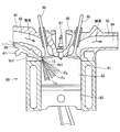
- the figure which shows the state which applied the fuel-injection apparatus by 1st Embodiment of this indication to the internal combustion engine.
- Sectional drawing which shows the nozzle hole of the fuel-injection apparatus by 1st Embodiment of this indication, and its vicinity.
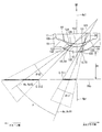
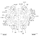
- the schematic diagram which shows the relationship of each nozzle hole of the fuel-injection apparatus by 1st Embodiment of this indication.
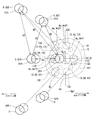
- the schematic diagram which shows the positional relationship of the fuel spray injected from the fuel-injection apparatus by 1st Embodiment of this indication.
- the schematic diagram which shows the positional relationship of the fuel spray injected from the fuel-injection apparatus by 5th Embodiment of this indication The schematic diagram which shows the positional relationship of the fuel spray injected from the fuel-injection apparatus by 6th Embodiment of this indication.
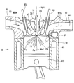
- FIG. 1 A fuel injection device according to a first embodiment of the present disclosure is shown in FIG.
- the fuel injection device 1 is applied to, for example, a gasoline engine (hereinafter simply referred to as “engine”) 80 as an internal combustion engine, and injects gasoline as fuel and supplies it to the engine 80 (see FIG. 2).
- engine a gasoline engine
- FIG. 2 A fuel injection device according to a first embodiment of the present disclosure is shown in FIG.
- engine 80 a gasoline engine 80 as an internal combustion engine, and injects gasoline as fuel and supplies it to the engine 80 (see FIG. 2).
- the engine 80 includes a cylindrical cylinder block 81, a piston 82, a cylinder head 90, an intake valve 95, an exhaust valve 96, and the like.
- the piston 82 is provided so as to be capable of reciprocating inside the cylinder block 81.
- the cylinder head 90 is provided to close the open end of the cylinder block 81.
- a combustion chamber 83 is formed between the inner wall of the cylinder block 81, the wall surface of the cylinder head 90, and the piston 82. The volume of the combustion chamber 83 increases or decreases as the piston 82 reciprocates.
- the cylinder head 90 has an intake manifold 91 and an exhaust manifold 93.
- An intake passage 92 is formed in the intake manifold 91.
- One end of the intake passage 92 is open to the atmosphere side, and the other end is connected to the combustion chamber 83.
- the intake passage 92 guides air sucked from the atmosphere side (hereinafter referred to as “intake”) to the combustion chamber 83.
- An exhaust passage 94 is formed in the exhaust manifold 93.
- the exhaust passage 94 has one end connected to the combustion chamber 83 and the other end opened to the atmosphere side.
- the exhaust passage 94 guides air containing combustion gas generated in the combustion chamber 83 (hereinafter referred to as “exhaust”) to the atmosphere side.
- the intake valve 95 is provided in the cylinder head 90 so as to be reciprocally movable by rotation of a cam of a driven shaft that rotates in conjunction with a drive shaft (not shown).
- the intake valve 95 can open and close between the combustion chamber 83 and the intake passage 92 by reciprocating.
- the exhaust valve 96 is provided in the cylinder head 90 so as to be reciprocally movable by rotation of the cam.
- the exhaust valve 96 can open and close between the combustion chamber 83 and the exhaust passage 94 by reciprocating.
- the fuel injection device 1 is mounted on the cylinder block 81 side of the intake passage 92 of the intake manifold 91.
- the fuel injection device 1 is provided such that the shaft is inclined with respect to the shaft of the combustion chamber 83 or is in a twisted relationship.
- the fuel injection device 1 is provided on the side of the combustion chamber 83. That is, the fuel injection device 1 is used by being mounted on the side of the engine 80.
- an ignition plug 97 as an ignition device is provided between the intake valve 95 and the exhaust valve 96 of the cylinder head 90, that is, at a position corresponding to the center of the combustion chamber 83.
- the spark plug 97 is provided at a position where the fuel injected from the fuel injection device 1 does not directly adhere and is capable of igniting an air-fuel mixture (combustible air) in which fuel and intake air are mixed.
- the engine 80 is a direct injection gasoline engine.
- the fuel injection device 1 is provided such that the plurality of injection holes 13 are exposed in a radially outer portion of the combustion chamber 83.
- the fuel injection device 1 is supplied with fuel pressurized to a fuel injection pressure by a fuel pump (not shown).
- a conical spray Fo is injected into the combustion chamber 83 from the plurality of injection holes 13 of the fuel injection device 1.
- Vc negative pressure
- the fuel injection device 1 includes a nozzle portion 10, a housing 20, a needle 30, a movable core 40, a fixed core 41, a spring 43 as a valve seat side biasing member, a coil 44, and the like.
- the nozzle portion 10 is formed of a metal such as martensitic stainless steel.
- the nozzle unit 10 is subjected to a quenching process so as to have a predetermined hardness.
- the nozzle portion 10 includes a nozzle cylinder portion 11, a nozzle bottom portion 12, an injection hole 13, and a valve seat 14.
- the nozzle cylinder portion 11 is formed in a cylindrical shape.
- the nozzle bottom 12 closes one end of the nozzle cylinder 11.
- the nozzle hole 13 is formed so as to connect the surface 121, that is, the inner wall, of the nozzle bottom portion 12 on the nozzle tube portion 11 side, and the surface 122, that is, the outer wall, on the opposite side of the nozzle tube portion 11 (see FIG. 3).
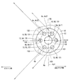
- a plurality of nozzle holes 13 are formed in the nozzle bottom 12. In the present embodiment, six nozzle holes 13 are formed (see FIG. 4).
- the valve seat 14 is formed in an annular shape around the nozzle hole 13 on the nozzle cylinder portion 11 side of the nozzle bottom portion 12. The nozzle hole 13 will be described in detail later.
- the housing 20 includes a nozzle holder 26, a first cylinder member 21, a second cylinder member 22, a third cylinder member 23, an inlet portion 24, a filter 25, and the like.
- the nozzle holder 26 is formed in a cylindrical shape from a magnetic material such as ferritic stainless steel. Inside the one end of the nozzle holder 26, an end portion of the nozzle cylinder portion 11 opposite to the nozzle bottom portion 12 is connected. The nozzle holder 26 and the nozzle part 10 are connected by welding, for example. Thereby, the nozzle holder 26 holds the nozzle unit 10.
- the first cylinder member 21, the second cylinder member 22, and the third cylinder member 23 are all formed in a substantially cylindrical shape.
- the 1st cylinder member 21, the 2nd cylinder member 22, and the 3rd cylinder member 23 are arrange
- the first cylinder member 21 and the third cylinder member 23 are made of a magnetic material such as ferritic stainless steel and subjected to a magnetic stabilization process.
- the first cylinder member 21 and the third cylinder member 23 have a relatively low hardness.
- the second cylindrical member 22 is formed of a nonmagnetic material such as austenitic stainless steel, for example.
- the hardness of the second cylinder member 22 is higher than the hardness of the first cylinder member 21 and the third cylinder member 23.
- the first cylinder member 21 is provided so that the outer wall at the end opposite to the second cylinder member 22 is fitted to the inner wall at the end opposite to the nozzle portion 10 of the nozzle holder 26.
- the inlet portion 24 is formed in a cylindrical shape from a magnetic material such as ferritic stainless steel.
- the inlet portion 24 is provided so that one end thereof is connected to the end portion of the third cylindrical member 23 opposite to the second cylindrical member 22.
- a fuel passage 100 is formed inside the housing 20.
- the fuel passage 100 is connected to the injection hole 13. That is, the nozzle cylinder part 11 forms the fuel passage 100 inside.
- a pipe (not shown) is connected to the inlet 24 on the side opposite to the third cylinder member 23. Thereby, the fuel from the fuel supply source (fuel pump) flows into the fuel passage 100 via the pipe.
- the fuel passage 100 guides fuel to the nozzle hole 13.
- the filter 25 is provided inside the inlet portion 24.
- the filter 25 collects foreign matters in the fuel flowing into the fuel passage 100.
- the needle 30 is formed in a rod shape from a metal such as martensitic stainless steel.
- the needle 30 is quenched so as to have a predetermined hardness.
- the hardness of the needle 30 is set substantially equal to the hardness of the nozzle portion 10.
- the needle 30 is accommodated in the housing 20 so as to be able to reciprocate in the fuel passage 100 in the axial direction of the housing 20.
- the needle 30 has a seat portion 31, a large diameter portion 32, and the like.
- the seat portion 31 is formed at an end portion of the needle 30 on the nozzle portion 10 side, and can contact the valve seat 14.
- the large diameter portion 32 is formed in the vicinity of the seat portion 31 at the end of the needle 30 on the valve seat 14 side.
- the large diameter portion 32 is set to have an outer diameter larger than the outer diameter of the end portion of the needle 30 on the valve seat 14 side.
- the large diameter portion 32 is formed so that the outer wall slides with the inner wall of the nozzle cylinder portion 11 of the nozzle portion 10. As a result, the needle 30 is guided to reciprocate in the axial direction at the end of the valve seat 14.
- the large-diameter portion 32 is formed with a notch 33 so that a plurality of portions in the circumferential direction of the outer wall are notched. Thereby, the fuel can flow between the notch 33 and the inner wall of the nozzle cylinder 11.
- the needle 30 opens and closes the injection hole 13 when the seat portion 31 is separated (separated) from the valve seat 14 or abuts (sits) the valve seat 14.
- the direction in which the needle 30 is separated from the valve seat 14 is referred to as the valve opening direction
- the direction in which the needle 30 contacts the valve seat 14 is referred to as the valve closing direction.
- the movable core 40 is formed in a cylindrical shape from a magnetic material such as ferritic stainless steel.
- the movable core 40 is subjected to a magnetic stabilization process.
- the hardness of the movable core 40 is relatively low and is substantially equal to the hardness of the first cylindrical member 21 and the third cylindrical member 23 of the housing 20.
- the movable core 40 has a first cylinder part 401 and a second cylinder part 402.
- the 1st cylinder part 401 and the 2nd cylinder part 402 are integrally formed so that it may become coaxial.
- the first cylindrical portion 401 is provided so that the inner wall at one end is fitted to the outer wall at the end opposite to the valve seat 14 of the needle 30.
- the movable core 40 and the needle 30 are connected by welding. Therefore, the movable core 40 can reciprocate in the housing 20 together with the needle 30 in the axial direction.
- the second tube portion 402 is connected to the other end of the first tube portion 401.
- the outer diameter of the second cylinder portion 402 is set larger than the outer diameter of the first cylinder portion 401.
- the first cylindrical portion 401 is formed with a radial hole portion 403 extending in the radial direction so as to connect the inner wall and the outer wall. Thereby, the fuel inside and outside the first tube portion 401 (movable core 40) can flow through the radial hole portion 403.
- the movable core 40 has a protruding portion 404 formed so as to protrude in an annular shape radially outward from the outer wall of the end portion of the second cylindrical portion 402 opposite to the first cylindrical portion 401.
- the protrusion 404 is slidable on the outer wall of the second cylindrical member 22 of the housing 20. Therefore, the movable core 40 is guided to reciprocate in the axial direction by the inner wall of the second cylindrical member 22. That is, the needle 30 and the movable core 40 are guided in the axial reciprocation in the fuel passage 100 by the inner wall of the nozzle cylinder portion 11 and the inner wall of the second cylinder member 22.
- the movable core 40 has a step surface 405 formed in an annular and flat shape inside the second cylindrical portion 402.
- the fixed core 41 is formed in a substantially cylindrical shape by a magnetic material such as ferritic stainless steel.
- the fixed core 41 is subjected to a magnetic stabilization process.
- the fixed core 41 has a relatively low hardness and is approximately equal to the hardness of the movable core 40.
- the fixed core 41 is provided on the opposite side of the movable core 40 from the valve seat 14.
- the fixed core 41 is provided inside the housing 20 so that the outer wall is connected to the inner walls of the second cylinder member 22 and the third cylinder member 23.
- the end surface of the fixed core 41 on the valve seat 14 side can contact the end surface of the movable core 40 on the fixed core 41 side.
- a cylindrical adjusting pipe 42 is press-fitted inside the fixed core 41.
- the spring 43 is, for example, a coil spring, and is provided between the adjusting pipe 42 inside the fixed core 41 and the step surface 405 of the movable core 40. One end of the spring 43 is in contact with the adjusting pipe 42. The other end of the spring 43 is in contact with the step surface 405.
- the spring 43 can urge the movable core 40 together with the needle 30 toward the valve seat 14, that is, in the valve closing direction. The biasing force of the spring 43 is adjusted by the position of the adjusting pipe 42 with respect to the fixed core 41.
- the coil 44 is formed in a substantially cylindrical shape, and is provided so as to surround the outer side in the radial direction of the second cylindrical member 22 and the third cylindrical member 23 in the housing 20.
- a cylindrical holder 45 is provided outside the coil 44 in the radial direction so as to cover the coil 44.
- the holder 45 is made of a magnetic material such as ferritic stainless steel.
- the holder 45 has an inner wall at one end connected to the outer wall of the nozzle holder 26 and an inner wall at the other end connected to the outer wall of the third cylindrical member 23.
- the coil 44 generates a magnetic force when electric power is supplied (energized).
- a magnetic force is generated in the coil 44, a magnetic circuit is formed in the fixed core 41, the movable core 40, the first cylindrical member 21, the nozzle holder 26, the holder 45, and the third cylindrical member 23.
- a magnetic attractive force is generated between the fixed core 41 and the movable core 40, and the movable core 40 is attracted to the fixed core 41 side together with the needle 30.
- the needle 30 moves in the valve opening direction, and the seat portion 31 is separated from the valve seat 14 and opened.
- the nozzle hole 13 is opened.
- the outer side in the radial direction of the third cylindrical member 23 and the coil 44 is molded by a molding portion 46 made of resin.
- a connector portion 47 is formed so as to protrude radially outward from the mold portion 46.
- the connector portion 47 is insert-molded with a terminal 471 for supplying power to the coil 44.
- the connector 47 is formed on one side when the housing 20 is divided into two parts on a virtual plane Vp1 including all the axes Ax1 of the nozzle cylinder 11.
- the fuel injection device 1 is provided in the engine 80 so that the piston 82 is positioned on one side of the virtual plane Vp1 and the spark plug 97 is positioned on the other side of the virtual plane Vp1.
- the fuel that has flowed from the inlet portion 24 flows between the filter 25, the fixed core 41 and the adjusting pipe 42, the spring 43, the movable core 40, the radial hole 403, between the needle 30 and the inner wall of the housing 20. 30 and the inner wall of the nozzle cylinder 11, that is, through the fuel passage 100 and guided to the injection hole 13.
- the periphery of the movable core 40 and the needle 30 is filled with fuel. Further, when the fuel injection device 1 is operated, the fuel flows through the radial hole 403 of the movable core 40. Therefore, the movable core 40 and the needle 30 can smoothly reciprocate in the axial direction inside the housing 20.
- the nozzle hole 13 has an inlet opening 131, an outlet opening 132, and a nozzle hole inner wall 133.
- the inlet opening 131 is formed on the surface 121 of the nozzle bottom 12 on the nozzle cylinder 11 side.
- the outlet opening 132 is formed on the surface 122 of the nozzle bottom 12 opposite to the nozzle cylinder 11.
- a flat surface portion 123 and a tapered portion 124 are formed on the surface 121.
- the flat portion 123 is formed in a circular flat shape at the center of the surface 121.
- the flat surface portion 123 is formed so that the axis Ax1 of the nozzle cylinder portion 11 passes through the center and is substantially orthogonal to the axis Ax1.
- the taper portion 124 is formed in an annular shape so as to continue to the radially outer side of the flat portion 123.
- the taper portion 124 is formed in a taper shape so as to move away from the axis Ax1 of the nozzle tube portion 11 as it goes from the flat surface portion 123 toward the nozzle tube portion 11 side.
- the inlet opening 131 is formed in the tapered portion 124.
- the injection hole inner wall 133 is connected to the inlet opening 131 and the outlet opening 132, and is formed in a tapered shape so as to move away from the central axis Ac as it goes from the inlet opening 131 to the outlet opening 132.
- each of the six nozzle holes 13 is referred to as nozzle holes 51, 52, 53, 54, 55, and 56.
- the nozzle holes 51, 52, 53, 54, 55, 56 are formed in this order so as to be arranged in the circumferential direction of the nozzle bottom 12 (see FIG. 4).
- the nozzle holes 51 to 56 are formed so that their centers are located on a virtual circle centered on the axis Ax1 of the nozzle cylinder portion 11.
- the injection holes 51, 52, and 56 are positioned on the ignition plug 97 side with respect to the virtual plane Vp1
- the injection holes 53, 54, and 55 are positioned on the piston 82 side with respect to the virtual plane Vp1.
- the engine 80 is provided.
- inlet opening 131 and the outlet opening 132 of the nozzle hole 13 are formed in the tapered portion 124 or the curved surface portion of the nozzle bottom portion 12, when viewed from the direction of the axis Ax1, it actually looks elliptical. In FIG. 4, it is shown as a circle for simplicity.
- the nozzle holes 51, 52, and 56 correspond to the “first nozzle holes” in the claims.
- the nozzle holes 54, 53, and 55 correspond to “second nozzle holes” in the claims.
- the group of the nozzle hole 51 and the nozzle hole 54, the group of the nozzle hole 52 and the nozzle hole 53, and the group of the nozzle hole 56 and the nozzle hole 55 respectively correspond to the “hole group” in the claims. is doing. That is, in this embodiment, the nozzle hole 13 includes three nozzle hole sets.
- the inlet opening 131, the outlet opening 132, the nozzle hole inner wall 133, and the central axis Ac of the nozzle hole 51 as the first nozzle hole are respectively referred to as “first inlet opening” and “first outlet opening” in the claims. Part “,” first nozzle hole inner wall “, and” first central axis ".
- the inlet opening 131, the outlet opening 132, the nozzle hole inner wall 133, and the central axis Ac of the nozzle hole 54 as the second nozzle hole are respectively referred to as “second inlet opening” and “second outlet opening” in the claims. Part “,” inner wall of the second nozzle hole ", and” second central axis ".
- the nozzle hole 51 as the first central axis
- the angle between the nozzle holes which is an angle formed by the center axis Ac11 and the center axis Ac12 of the nozzle hole 54 as the second center axis, is ⁇ (deg), and the first nozzle hole in the cross section of the virtual plane including the first center axis Ac11.
- the first taper angle which is the angle formed by the contour of the nozzle hole inner wall 133 of the nozzle hole 51 as the inner wall, is ⁇ t1 (deg), and the nozzle hole as the second nozzle hole inner wall in the cross section by the virtual plane that includes all the second central axis Ac12
- a second taper angle that is an angle formed by the contour of the inner wall 133 of the nozzle hole 54 is ⁇ t2 (deg)
- an average pressure of the fuel in the fuel passage 100 when fuel is injected from the nozzle hole 13 is P (Mpa).
- the nozzle hole 51 as the first nozzle hole and the second The injection holes 54 as holes, ⁇ ⁇ ⁇ t1 + ⁇ t2 ⁇ 0.87 ⁇ P ⁇ 0.52 Equation 1 It is formed to satisfy the relationship.
- ⁇ in Equation 1 means a power.
- the first nozzle hole and the second nozzle hole are ⁇ t1 + ⁇ t2-10 ⁇ ⁇ Equation 2 It is formed to satisfy the relationship.
- the above formulas also apply to the first and second nozzle holes of the other nozzle hole groups (the nozzle hole group of the nozzle hole 52 and the nozzle hole 53 and the nozzle hole group of the nozzle hole 56 and the nozzle hole 55). 1 and Formula 2 are satisfied.
- the first central axis and the second central axis are in a twisted relationship.
- the nozzle hole angle ⁇ corresponds to an angle formed between the first central axis and a straight line extending in parallel with the second central axis from one point on the first central axis.
- the pressure of the fuel in the fuel passage 100 assumed when using the fuel injection device 1 of the present embodiment of the present embodiment is, for example, about 20 MPa. Therefore, in this embodiment, P is 20 (MPa), and ⁇ 0.87 ⁇ P ⁇ 0.52 is about ⁇ 4 (deg).
- the taper angles ( ⁇ t1, ⁇ t2) of the nozzle holes 51 to 56 are set to about 18 (deg), for example. Therefore, from Equations 1 and 2, 26 ⁇ ⁇ ⁇ 32 (deg) It is. Also, ⁇ ( ⁇ t1 + ⁇ t2) / 2 ⁇ 14 (deg) It is.
- the fuel spray injected from the nozzle holes 51 to 56 flies in the direction of the arrow along the central axis Ac of each nozzle hole.
- the first central axis Ac11 of the first nozzle hole group (for example, the nozzle hole group of the nozzle holes 51 and 54) which is one nozzle hole group selected from the three nozzle hole groups.
- the second central axis Ac12 and the second nozzle hole group (for example, the nozzle hole group of the nozzle hole 52 and the nozzle hole 53) different from the first nozzle hole group among the three nozzle hole groups.
- the angle between the nozzle hole groups which is an angle formed with one central axis Ac21 or the second central axis Ac22, is ⁇ (deg)
- the first nozzle hole group and the second nozzle hole group are: ⁇ ⁇ Equation 3 It is formed to satisfy the relationship.
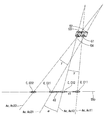
- a specific virtual plane SVp (see FIG. 3) that is a virtual plane that is a predetermined distance Dt away from the nozzle bottom 12 on the side opposite to the nozzle cylinder 11 and orthogonal to the axis Ax1 of the nozzle cylinder 11 and each injection
- a circle formed by a line of intersection with the conical imaginary plane including all the nozzle hole inner walls 133 of the holes 13 is defined as C.
- a circle formed by the intersection of the specific virtual plane SVp and the conical virtual plane including all the first injection hole inner walls of the first injection hole group (for example, the injection hole group of the injection hole 51 and the injection hole 54) is defined as C11.
- C12 is a circle formed by the intersection of the specific virtual plane SVp and the conical virtual plane including all the inner walls of the second injection holes of the first injection hole set
- C21 is a circle formed by a line of intersection with the conical imaginary surface including the first inner wall of the first nozzle hole), and the second virtual hole inner wall of the second virtual hole group and the specific virtual plane SVp.
- the first nozzle hole set and the second injection hole The hole set is d1 ⁇ d2 (Formula 4) It is formed to satisfy the relationship. The same applies to the relationship between the other nozzle hole sets (the nozzle hole set of the nozzle holes 56 and 55).
- each nozzle hole 13 has a virtual plane Vp1 formed by a circle C formed by the intersection of the specific virtual plane SVp and the conical virtual plane including all the nozzle inner walls 133 of each nozzle hole 13. On the other hand, it is formed to be located on the piston 82 side.
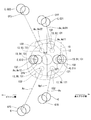
- FIG. 6 shows alternate lines (Cf1 to Cf6) between the contours of the fuel sprays injected from the nozzle holes 51 to 56 and the specific virtual plane SVp by two-dot chain lines.
- the fuel spray from the nozzle hole 51 and the nozzle hole 54 The Coanda effect is effective between the fuel spray, the fuel spray from the nozzle hole 52 and the fuel spray from the nozzle hole 53, and the fuel spray from the nozzle hole 56 and the fuel spray from the nozzle hole 55.
- the center of Cf1 is located approximately on C11
- the center of Cf4 is approximately located on C12.
- the center of Cf2 is located approximately on C21
- the center of Cf3 is approximately located on C22.
- 3 to 6 and the like are schematic diagrams and do not accurately represent the taper angle, the angle between the nozzle holes, the angle between the nozzle holes, the distance, and the like.
- first central axis and the second central axis and the specific virtual plane SVp intersect with each other at an inclination, C11, C12, C21, C22, and Cf1 to 6 appear to be elliptical when viewed from the direction of the axis Ax1.
- FIGS. 4 and 6 it is shown as a circle for simplicity.
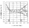
- Coanda influence degree the degree of influence of the Coanda effect (hereinafter referred to as “Coanda influence degree” as appropriate) is expressed as “angle ⁇ 20 MPa at which the spray Fo is attracted when P is 20” and “spray when P is 4. It is defined by the ratio to the angle ⁇ 4 MPa at which Fo is attracted, and is indicated on the vertical axis.
- the Coanda influence degree is about 0.8 to 1.4. Therefore, in this range, the degree of influence of the Coanda effect becomes unstable, and the Coanda effect is stably generated between the fuel spray injected from the first injection hole and the fuel spray injected from the second injection hole. This proves difficult.
- the fuel sprays may collide with each other, and the fuel spray particle size may increase.
- the nozzle holes 51 to 56 are formed so as to satisfy the relationship of the above formulas 1 and 2, the fuel spray is effectively generated between the fuel sprays in one nozzle hole set. Collisions between each other can be suppressed.
- the fuel injection device 1 of this embodiment includes the nozzle unit 10.
- the nozzle portion 10 includes a nozzle tube portion 11 that forms a fuel passage 100 on the inside, a nozzle bottom portion 12 that closes one end of the nozzle tube portion 11, a surface 121 on the nozzle tube portion 11 side of the nozzle bottom portion 12, and the nozzle tube portion 11.
- the nozzle hole 13 is a nozzle hole group including one first nozzle hole (the nozzle hole 51, the nozzle hole 52, or the nozzle hole 56) and one second nozzle hole (the nozzle hole 54, the nozzle hole 53, or the nozzle hole 55). At least one (a set of the injection hole 51 and the injection hole 54, a set of the injection hole 52 and the injection hole 53, and a set of the injection hole 56 and the injection hole 55) is included.
- the nozzle holes 51, 52, and 56 as the first nozzle holes are the inlet opening 131 as the first inlet opening formed on the surface 121 of the nozzle bottom 12 on the nozzle cylinder 11 side, and the nozzle cylinder of the nozzle bottom 12 11, an outlet opening 132 as a first outlet opening formed on the surface 122 opposite to the surface 11, and the inlet opening 131 and the outlet opening 132 are connected to each other from the inlet opening 131 side to the outlet opening 132 side.
- a nozzle hole inner wall 133 is formed as a first nozzle hole inner wall formed in a taper shape so as to be away from the center axis Ac1 as the first center axis as it goes toward.
- the nozzle holes 54, 53, 55 as the second nozzle holes are the inlet opening 131 as the second inlet opening formed on the surface 121 of the nozzle bottom 12 on the nozzle cylinder 11 side, and the nozzle cylinder of the nozzle bottom 12. 11, the outlet opening 132 formed as the second outlet opening formed on the surface 122 opposite to the surface 11, and the inlet opening 131 and the outlet opening 132 are connected to the outlet opening 132 side from the inlet opening 131 side.
- a nozzle hole inner wall 133 as a second nozzle hole inner wall is formed in a tapered shape so as to move away from the center axis Ac1 as the second center axis as it goes toward.
- first nozzle hole group the nozzle hole group of the nozzle hole 51 and the nozzle hole 54
- the central axis Ac11 and the second central axis of the nozzle hole 51 as the first central axis.
- the angle between the nozzle holes 54 which is the angle formed by the center axis Ac12 of the nozzle hole 54 as ⁇ , is ⁇ (deg), and the injection of the nozzle hole 51 as the inner wall of the first nozzle hole in the cross section by the virtual plane including all the first center axis Ac11
- the second taper angle that is an angle formed by ⁇ t2 (deg) and the average pressure of the fuel in the fuel passage 100 when the fuel is injected from the injection hole 13 is P (Mpa).
- the hole 51 and the nozzle hole 54 as the second nozzle hole are ⁇ ⁇ ⁇ t1 + ⁇ t2 ⁇ 0.87 ⁇ P ⁇ 0.52 Equation 1 It is formed to satisfy the relationship.
- the first nozzle hole and the second nozzle hole are formed so as to satisfy Formula 1, the fuel spray injected from the first nozzle hole and the fuel spray injected from the second nozzle hole In the meantime, the Coanda effect can be effectively generated.
- the inner wall of the first injection hole and the inner wall of the second injection hole are formed in a tapered shape, fuel is injected from the first injection hole or the second injection hole so as to expand. Therefore, the spray angle of the fuel spray injected from each nozzle hole 13 when the fuel pressure in the fuel passage 100 is high, and the fuel injected from each nozzle hole 13 when the fuel pressure in the fuel path 100 is low. The difference between the spray angle and the spray angle can be reduced. Therefore, even if the pressure of the fuel in the fuel passage 100 fluctuates, fluctuations in the spray angle of the fuel spray injected from the first nozzle hole or the second nozzle hole can be suppressed.
- the Coanda effect can be stably generated between the fuel spray injected from the first nozzle hole and the fuel spray injected from the second nozzle hole regardless of the fluctuation of the fuel pressure. Therefore, it is possible to stably generate a dense air-fuel mixture atomized on the center side between fuel sprays regardless of fluctuations in fuel pressure.
- the first nozzle hole and the second nozzle hole are: ⁇ t1 + ⁇ t2-10 ⁇ ⁇ Equation 2 It is formed to satisfy the relationship. Therefore, it can suppress that fuel spray collides and the atomization of fuel spray is prevented in the center side between fuel sprays.
- the nozzle hole 13 includes three nozzle hole groups.
- the first central axis or the second central axis of the first nozzle hole group which is one nozzle hole group selected from the three nozzle hole groups, and a different jet from the first nozzle hole group among the plurality of nozzle hole groups
- the angle between the nozzle hole groups which is the angle formed with the first central axis or the second central axis of the second nozzle hole group, which is a hole group
- the first nozzle hole group and the second nozzle hole group are , ⁇ ⁇ Equation 3 It is formed to satisfy the relationship. Therefore, the Coanda effect is effectively generated between the fuel sprays injected from one nozzle hole set, and the Coanda effect is not generated as much as possible between the fuel sprays injected from the other nozzle hole sets. can do. Therefore, in a configuration having a plurality of nozzle hole sets, a dense air-fuel mixture atomized on the center side between fuel sprays can be more stably generated regardless of fluctuations in fuel pressure.
- the specific virtual plane SVp and the first injection hole which are virtual planes that are separated from the nozzle bottom 12 by a predetermined distance Dt on the opposite side of the nozzle cylinder 11 and orthogonal to the axis Ax1 of the nozzle cylinder 11.
- C11 a circle formed by a line of intersection with a conical virtual surface including all the first inner wall of the first nozzle hole, and a conical virtual surface including all of the specific virtual plane SVp and the second inner wall of the first nozzle hole group
- a circle formed by the intersection line of C12, a circle formed by the intersection line of the specific virtual plane SVp and the conical virtual surface including all the inner walls of the first injection hole of the second injection hole set, C21, the specific virtual plane SVp and the second If the circle formed by the intersection line with the conical imaginary plane including the entire inner wall of the second nozzle hole of the nozzle hole set is C22, the distance between C11 and C12 is d1, and the distance between C11 or C12 and C21 or C22 is d2.
- the first nozzle hole set and the second nozzle hole set are: d1 ⁇ d2 (Formula 4) It is formed to satisfy the relationship. Therefore, the Coanda effect is effectively generated between the fuel sprays injected from one nozzle hole set, and the Coanda effect is not generated as much as possible between the fuel sprays injected from the other nozzle hole sets. can do. Therefore, in the configuration having a plurality of nozzle hole sets, a dense air-fuel mixture atomized on the center side between fuel sprays can be generated more stably regardless of fluctuations in fuel pressure.
- the nozzle portion 10 has a valve seat 14 formed on the inner wall.
- the fuel injection device 1 according to this embodiment further includes a housing 20, a needle 30, a movable core 40, a fixed core 41, a coil 44, and a spring 43.
- the housing 20 is formed in a cylindrical shape and is connected to the nozzle cylinder portion 11 on the side opposite to the nozzle bottom portion 12.
- the needle 30 is provided inside the housing 20 so that one end thereof can contact the valve seat 14 and can reciprocate in the axial direction, and when the one end is separated from the valve seat 14 or contacts the valve seat 14, the nozzle hole 13.
- the movable core 40 is provided so as to be able to reciprocate in the housing 20 together with the needle 30.
- the fixed core 41 is provided on the side opposite to the valve seat 14 of the movable core 40 inside the housing 20.
- the coil 44 When energized, the coil 44 can attract the movable core 40 toward the fixed core 41 and move the needle 30 to the opposite side of the valve seat 14.
- the spring 43 can bias the needle 30 and the movable core 40 toward the valve seat 14.
- the fuel injection device 1 of the present embodiment is an electromagnetically driven fuel injection device.
- the injection hole 51 has an ignition plug 97 with respect to the virtual plane Vp1 such that a circle C formed by a line of intersection between the specific virtual plane SVp and the conical virtual plane including all the injection hole inner walls 133 of the injection hole 51. It is formed to be located on the side.
- the nozzle holes 53, 54, and 55 are such that the circle C formed by the intersection of the specific virtual plane SVp and the conical virtual surface including the nozzle hole inner wall 133 of each of the nozzle holes 53, 54, and 55 is a piston with respect to the virtual plane Vp1. It is formed to be located on the 82 side.
- 2nd Embodiment is the same as that of 1st Embodiment except the point mentioned above.
- FIG. 9 shows a part of the fuel injection device according to the third embodiment of the present disclosure.
- the first central axis Ac11 of the first nozzle hole group (for example, the nozzle hole group of the nozzle hole 51 and the nozzle hole 54) which is one nozzle hole group selected from the three nozzle hole groups, or
- the second central axis Ac12 and the first of the second nozzle hole groups (for example, the nozzle hole group of the nozzle holes 52 and 53) that are different from the first nozzle hole group among the three nozzle hole groups.
- the angle between the nozzle hole groups which is an angle formed with the central axis Ac21 or the second central axis Ac22, is ⁇ (deg)
- the first nozzle hole group and the second nozzle hole group are: ⁇ ⁇ Equation 3 It is formed to satisfy the relationship.
- the intersection line between the specific virtual plane SVp and the conical virtual surface including all the first inner hole walls of the first injection hole group (for example, the injection hole group of the injection hole 51 and the injection hole 54).
- a circle formed by C11, a circle formed by the intersection of the specific virtual plane SVp and the conical virtual plane including all the inner walls of the second nozzle holes of the first nozzle hole set, C12, the specified virtual plane and the second nozzle hole set is C21, the specific virtual plane SVp and the second nozzle hole second If the circle formed by the intersecting line with the conical imaginary surface including all the inner walls of the two nozzle holes is C22, the distance between C11 and C12 is d1, and the distance between C11 or C12 and C21 or C22 is d2, the first nozzle hole The set and the second nozzle hole set are
- the first nozzle hole group and the second nozzle hole group are formed so as to satisfy the relationship of the above equation 5 instead of the above equation 4.
- the first nozzle hole group and the second nozzle hole group are formed so as to satisfy the relationship of the above formula 3. Therefore, also in 3rd Embodiment, there can exist an effect similar to 1st Embodiment.
- FIGS. 1 A fuel injection device according to a fourth embodiment of the present disclosure is shown in FIGS.
- the fourth embodiment differs from the first embodiment in the mounting position of the fuel injection device 1 and the like on the engine 80.
- the fuel injection device 1 is mounted between the intake valve 95 and the exhaust valve 96 of the cylinder head 90, that is, at a position corresponding to the center of the combustion chamber 83.
- the fuel injection device 1 is provided so that its axis is substantially parallel to or substantially coincident with the axis of the combustion chamber 83.
- the fuel injection device 1 is mounted in the center on the upper side in the vertical direction of the engine 80. That is, the fuel injection device 1 is used by being mounted on the engine 80 in the center.
- the spark plug 97 is located on the cylinder block 81 side of the exhaust manifold 93 at a position where fuel injected from the fuel injection device 1 does not directly adhere to the mixture (combustible air) in which fuel and intake air are mixed. It is provided at a position where ignition is possible.
- the fuel injection device 1 is provided in the engine 80 such that the exhaust valve 96 and the spark plug 97 are positioned on the other side of the virtual plane Vp1 so that the intake valve 95 is positioned on one side of the virtual plane Vp1.
- the fuel injection device 1 is provided such that the plurality of injection holes 13 are exposed at a portion of the combustion chamber 83 opposite to the piston 82 in the axial direction.
- a conical spray Fo is injected into the combustion chamber 83 from the plurality of injection holes 13 of the fuel injection device 1.
- the fuel injection device 1 has the nozzle holes 52 and 55 with respect to the virtual plane Vp1 such that the nozzle holes 51 and 56 are located on the exhaust valve 96 side with respect to the virtual plane Vp1.
- the nozzle holes 53 and 54 are provided in the engine 80 so as to be located on the intake valve 95 side with respect to the virtual plane Vp1 so as to be located slightly on the intake valve 95 side.
- the nozzle hole 13 has three nozzle hole groups (a nozzle hole group of the nozzle hole 51 and the nozzle hole 52, a nozzle hole group of the nozzle hole 53 and the nozzle hole 54, and a nozzle hole 55 and the nozzle hole 56. And nozzle hole set).
- the central axis Ac11 and the second center of the nozzle hole 51 as the first central axis.
- An angle between the nozzle holes which is an angle formed with the central axis Ac12 of the nozzle hole 52 as an axis, is ⁇ (deg), and the nozzle hole 51 as the inner wall of the first nozzle hole in a cross section by a virtual plane including all of the first central axis Ac11
- the first taper angle which is the angle formed by the contour of the nozzle hole inner wall 133, is ⁇ t1 (deg), and the nozzle hole inner wall 133 of the nozzle hole 52 as the second nozzle hole inner wall in the cross section of the virtual plane including the second central axis Ac12.
- the first nozzle hole and the second nozzle hole are ⁇ t1 + ⁇ t2-10 ⁇ ⁇ Equation 2 It is formed to satisfy the relationship.
- the first central axis Ac11 or the second central axis of the first nozzle hole group (for example, the nozzle hole group of the nozzle hole 51 and the nozzle hole 52) which is one nozzle hole group selected from the three nozzle hole groups.
- Ac12 and the first central axis Ac21 of the second nozzle hole group (for example, the nozzle hole group of the nozzle hole 53 and the nozzle hole 54) which is different from the first nozzle hole group among the three nozzle hole groups, or If the angle between the nozzle hole groups, which is an angle formed with the second central axis Ac22, is ⁇ (deg), the first nozzle hole group and the second nozzle hole group are: ⁇ ⁇ Equation 3 It is formed to satisfy the relationship.
- the intersection line between the specific virtual plane SVp and the conical virtual surface including all the first inner wall of the first injection hole group for example, the injection hole group of the injection hole 51 and the injection hole 52.
- a circle formed by C11, a circle formed by the intersection of the specific virtual plane SVp and the conical virtual plane including all the inner walls of the second nozzle holes of the first nozzle hole set, C12, the specified virtual plane and the second nozzle hole set for example, a circle formed by a line of intersection with a conical imaginary plane including all inner walls of the first injection hole of the injection hole set of the injection hole 53 and the injection hole 54 is C21, the specified virtual plane SVp and the second of the second injection hole set
- the circle formed by the intersecting line with the conical imaginary surface including all the inner walls of the two nozzle holes is C22, the distance between C11 and C12 is d1, and the distance between C11 or C12 and C21 or C22 is d2, the first nozzle hole The set and the second nozzle hole
- FIG. 12 shows a part of the fuel injection device according to the fifth embodiment of the present disclosure.
- the fifth embodiment is different from the fourth embodiment in how the fuel injection device 1 is mounted on the engine 80.
- the nozzle holes 53, 54, and 55 are in the intake valve 95 with respect to the virtual plane Vp1 so that the nozzle holes 51, 52, and 56 are located on the exhaust valve 96 side with respect to the virtual plane Vp1. It is provided in the engine 80 so as to be located on the side.
- the nozzle hole 13 includes three nozzle hole groups (a nozzle hole group including the nozzle hole 51 and the nozzle hole 52, a nozzle hole group including the nozzle hole 53 and the nozzle hole 54, and a nozzle hole 55 and the nozzle hole 56. And nozzle hole set).
- the nozzle holes 51 to 56 are formed so as to satisfy the relationship of the above formulas 1 and 2. Further, the three nozzle hole groups are formed so as to satisfy the relationship of the above formula 3.
- the distance between the outlet opening 132 of the nozzle hole 51 and the axis Ax1 is set larger than the distance between the outlet opening 132 of the nozzle holes 52 to 56 and the axis Ax1.
- FIG. 13 shows a part of the fuel injection device according to the sixth embodiment of the present disclosure.
- the sixth embodiment is different from the fifth embodiment in how the fuel injection device 1 is mounted on the engine 80.
- the nozzle holes 52, 53, and 54 are in the intake valve 95 with respect to the virtual plane Vp1, so that the nozzle holes 51, 55, and 56 are located on the exhaust valve 96 side with respect to the virtual plane Vp1. It is provided in the engine 80 so as to be located on the side.
- the nozzle hole 13 includes three nozzle hole groups (a nozzle hole group including the nozzle hole 51 and the nozzle hole 52, a nozzle hole group including the nozzle hole 53 and the nozzle hole 54, and a nozzle hole 55 and the nozzle hole 56. And nozzle hole set).
- the nozzle holes 51 to 56 are formed so as to satisfy the relationship of the above formulas 1 and 2. Further, the three nozzle hole groups are formed so as to satisfy the relationship of the above formula 3.
- the distances between the outlet openings 132 of the nozzle holes 51 to 56 and the axis Ax1 are all set equal.
- the first nozzle hole and the second nozzle hole may be formed so as to satisfy only Formula 1 above. That is, the first nozzle hole and the second nozzle hole may not be formed so as to satisfy the above formula 2. Further, the first nozzle hole group and the second nozzle hole group may not be formed so as to satisfy the above expressions 3 and 4. As in the first embodiment, the first injection hole and the second injection hole are formed so as to satisfy the above expressions 1 and 2, and the first injection hole group and the second injection hole group satisfy the above expressions 3 and 4. When formed in this way, the various effects shown in the first embodiment can be achieved.
- the injection hole 13 may include one, two, or four or more injection hole sets.
- ⁇ t1 and ⁇ t2 may be set to any values as long as they are larger than 0 and smaller than 90, respectively.
- the movable core 40 is provided so as to be movable relative to the needle 30, and the needle 30 may have a surface that can contact the movable core 40 on the valve seat 14 side. Good.
- the nozzle cylinder portion 11 of the nozzle portion 10 and the first cylinder member 21 of the housing 20 may be integrally formed. Moreover, the nozzle cylinder part 11 and the nozzle bottom part 12 may be formed separately.
- the fuel injection device does not include the valve seat 14, the housing 20, the needle 30, the movable core 40, the fixed core 41, the coil 44, and the spring 43, and includes only the nozzle unit 10. It is good also as attaching to the fuel supply part to which fuel is supplied intermittently or continuously, and injecting fuel from the nozzle hole 13.
- the average pressure P in the fuel passage 100 when fuel is injected from the injection hole 13 is not limited to 20 Mpa, and may be, for example, about 20 to 100 Mpa.
- the fuel injection device is applied to a direct injection gasoline engine.
- the fuel injection device may be applied to, for example, a diesel engine or a port injection type gasoline engine.
Landscapes
- Engineering & Computer Science (AREA)
- Chemical & Material Sciences (AREA)
- Combustion & Propulsion (AREA)
- Mechanical Engineering (AREA)
- General Engineering & Computer Science (AREA)
- Physics & Mathematics (AREA)
- Electromagnetism (AREA)
- Fuel-Injection Apparatus (AREA)
Priority Applications (3)
| Application Number | Priority Date | Filing Date | Title |
|---|---|---|---|
| US16/069,228 US10677209B2 (en) | 2016-02-24 | 2017-01-27 | Fuel injection device |
| DE112017000966.9T DE112017000966T5 (de) | 2016-02-24 | 2017-01-27 | Kraftstoffeinspritzvorrichtung |
| CN201780007902.XA CN108495996B (zh) | 2016-02-24 | 2017-01-27 | 燃料喷射装置 |
Applications Claiming Priority (2)
| Application Number | Priority Date | Filing Date | Title |
|---|---|---|---|
| JP2016-033050 | 2016-02-24 | ||
| JP2016033050A JP6451663B2 (ja) | 2016-02-24 | 2016-02-24 | 燃料噴射装置 |
Publications (1)
| Publication Number | Publication Date |
|---|---|
| WO2017145639A1 true WO2017145639A1 (ja) | 2017-08-31 |
Family
ID=59686141
Family Applications (1)
| Application Number | Title | Priority Date | Filing Date |
|---|---|---|---|
| PCT/JP2017/002841 Ceased WO2017145639A1 (ja) | 2016-02-24 | 2017-01-27 | 燃料噴射装置 |
Country Status (5)
| Country | Link |
|---|---|
| US (1) | US10677209B2 (enExample) |
| JP (1) | JP6451663B2 (enExample) |
| CN (1) | CN108495996B (enExample) |
| DE (1) | DE112017000966T5 (enExample) |
| WO (1) | WO2017145639A1 (enExample) |
Families Citing this family (2)
| Publication number | Priority date | Publication date | Assignee | Title |
|---|---|---|---|---|
| JP7272645B2 (ja) * | 2019-06-20 | 2023-05-12 | 株式会社デンソー | 燃料噴射弁 |
| JP7419997B2 (ja) * | 2020-07-14 | 2024-01-23 | 株式会社デンソー | 燃料噴射弁 |
Citations (3)
| Publication number | Priority date | Publication date | Assignee | Title |
|---|---|---|---|---|
| JP2002221128A (ja) * | 2001-01-25 | 2002-08-09 | Nippon Soken Inc | 噴射弁 |
| JP2005194929A (ja) * | 2004-01-06 | 2005-07-21 | Toyota Motor Corp | 筒内噴射式内燃機関 |
| JP2015025392A (ja) * | 2013-07-25 | 2015-02-05 | トヨタ自動車株式会社 | 燃料噴射弁 |
Family Cites Families (17)
| Publication number | Priority date | Publication date | Assignee | Title |
|---|---|---|---|---|
| SU1086204A1 (ru) * | 1980-10-14 | 1984-04-15 | Ярославский завод дизельной аппаратуры | Распылитель форсунки дл двигател внутреннего сгорани |
| JP2000320429A (ja) * | 1999-05-13 | 2000-11-21 | Denso Corp | 燃料噴射ノズル |
| DE10059420A1 (de) * | 2000-11-30 | 2002-06-06 | Bosch Gmbh Robert | Brennstoffeinspritzventil |
| JP3899937B2 (ja) * | 2002-01-18 | 2007-03-28 | 株式会社デンソー | 燃料噴射弁 |
| DE10315821A1 (de) * | 2002-11-11 | 2004-05-27 | Robert Bosch Gmbh | Kraftstoffeinspritzventil für Brennkraftmaschinen |
| JP4024144B2 (ja) | 2002-12-26 | 2007-12-19 | 株式会社日本自動車部品総合研究所 | 燃料噴射装置 |
| US7032566B2 (en) * | 2003-05-30 | 2006-04-25 | Caterpillar Inc. | Fuel injector nozzle for an internal combustion engine |
| EP1517017B1 (en) | 2003-09-22 | 2008-04-16 | Mazda Motor Corporation | Spark-ignition direct-injection engine |
| JP4085944B2 (ja) | 2003-09-22 | 2008-05-14 | マツダ株式会社 | 火花点火式直噴エンジン |
| JP2006233923A (ja) * | 2005-02-28 | 2006-09-07 | Denso Corp | 燃料噴射弁 |
| EP2484890B8 (en) * | 2007-03-27 | 2015-05-06 | Mitsubishi Electric Corporation | Fuel injection valve |
| JP4808801B2 (ja) | 2009-05-18 | 2011-11-02 | 三菱電機株式会社 | 燃料噴射弁 |
| JP5395007B2 (ja) | 2010-07-22 | 2014-01-22 | 日立オートモティブシステムズ株式会社 | 燃料噴射弁およびそれを搭載した車両用内燃機関 |
| JP5668984B2 (ja) | 2011-05-31 | 2015-02-12 | 株式会社デンソー | 燃料噴射装置 |
| JP5295311B2 (ja) * | 2011-06-09 | 2013-09-18 | 三菱電機株式会社 | 燃料噴射弁 |
| JP6214255B2 (ja) | 2013-07-16 | 2017-10-18 | 株式会社Subaru | インジェクタ |
| JP6207481B2 (ja) | 2014-07-31 | 2017-10-04 | 株式会社 渡辺ドライ | 包装収納物 |
-
2016
- 2016-02-24 JP JP2016033050A patent/JP6451663B2/ja active Active
-
2017
- 2017-01-27 US US16/069,228 patent/US10677209B2/en active Active
- 2017-01-27 WO PCT/JP2017/002841 patent/WO2017145639A1/ja not_active Ceased
- 2017-01-27 DE DE112017000966.9T patent/DE112017000966T5/de active Pending
- 2017-01-27 CN CN201780007902.XA patent/CN108495996B/zh active Active
Patent Citations (3)
| Publication number | Priority date | Publication date | Assignee | Title |
|---|---|---|---|---|
| JP2002221128A (ja) * | 2001-01-25 | 2002-08-09 | Nippon Soken Inc | 噴射弁 |
| JP2005194929A (ja) * | 2004-01-06 | 2005-07-21 | Toyota Motor Corp | 筒内噴射式内燃機関 |
| JP2015025392A (ja) * | 2013-07-25 | 2015-02-05 | トヨタ自動車株式会社 | 燃料噴射弁 |
Also Published As
| Publication number | Publication date |
|---|---|
| US20190003437A1 (en) | 2019-01-03 |
| CN108495996A (zh) | 2018-09-04 |
| DE112017000966T5 (de) | 2018-12-13 |
| US10677209B2 (en) | 2020-06-09 |
| JP6451663B2 (ja) | 2019-01-16 |
| CN108495996B (zh) | 2020-06-30 |
| JP2017150377A (ja) | 2017-08-31 |
Similar Documents
| Publication | Publication Date | Title |
|---|---|---|
| US10890152B2 (en) | Fuel injection device | |
| JP5668984B2 (ja) | 燃料噴射装置 | |
| JP6292188B2 (ja) | 燃料噴射装置 | |
| US6845930B2 (en) | Spray pattern and spray distribution control with non-angled orifices in fuel injection metering disc and methods | |
| JP5943060B2 (ja) | 燃料噴射装置 | |
| JP6451663B2 (ja) | 燃料噴射装置 | |
| US6820826B2 (en) | Spray targeting to an arcuate sector with non-angled orifices in fuel injection metering disc and method | |
| JP6590037B2 (ja) | 燃料噴射装置 | |
| CN113994085B (zh) | 燃料喷射阀 | |
| US12012916B2 (en) | Fuel injection valve | |
| WO2018037994A1 (ja) | 燃料噴射弁 | |
| WO2017022439A1 (ja) | 燃料噴射装置 | |
| WO2017126293A1 (ja) | 燃料噴射装置 | |
| CN115803516A (zh) | 燃料喷射阀 | |
| WO2016163086A1 (ja) | 燃料噴射装置 | |
| JP2021167586A (ja) | 燃料噴射弁 | |
| JP2017020394A (ja) | 燃料噴射装置 | |
| JP2016169739A (ja) | 燃料噴射装置 |
Legal Events
| Date | Code | Title | Description |
|---|---|---|---|
| 121 | Ep: the epo has been informed by wipo that ep was designated in this application |
Ref document number: 17756081 Country of ref document: EP Kind code of ref document: A1 |
|
| 122 | Ep: pct application non-entry in european phase |
Ref document number: 17756081 Country of ref document: EP Kind code of ref document: A1 |