WO2017142084A1 - Device for electrolytic etching and method for extracting metal compound particles - Google Patents
Device for electrolytic etching and method for extracting metal compound particles Download PDFInfo
- Publication number
- WO2017142084A1 WO2017142084A1 PCT/JP2017/005995 JP2017005995W WO2017142084A1 WO 2017142084 A1 WO2017142084 A1 WO 2017142084A1 JP 2017005995 W JP2017005995 W JP 2017005995W WO 2017142084 A1 WO2017142084 A1 WO 2017142084A1
- Authority
- WO
- WIPO (PCT)
- Prior art keywords
- metal
- electrolytic
- cathode
- electrolytic etching
- metal compound
- Prior art date
Links
- 238000000866 electrolytic etching Methods 0.000 title claims abstract description 43
- 239000011817 metal compound particle Substances 0.000 title claims abstract description 22
- 238000000034 method Methods 0.000 title claims description 32
- 229910052751 metal Inorganic materials 0.000 claims abstract description 147
- 239000002184 metal Substances 0.000 claims abstract description 141
- 239000008151 electrolyte solution Substances 0.000 claims abstract description 72
- 239000007769 metal material Substances 0.000 claims abstract description 30
- 238000000605 extraction Methods 0.000 claims abstract description 22
- 239000002904 solvent Substances 0.000 claims abstract description 17
- 239000003125 aqueous solvent Substances 0.000 claims abstract description 14
- 239000003795 chemical substances by application Substances 0.000 claims abstract description 11
- 150000002736 metal compounds Chemical class 0.000 claims description 36
- OKKJLVBELUTLKV-UHFFFAOYSA-N Methanol Chemical compound OC OKKJLVBELUTLKV-UHFFFAOYSA-N 0.000 claims description 32
- 150000001875 compounds Chemical class 0.000 claims description 31
- 239000003792 electrolyte Substances 0.000 claims description 25
- VILCJCGEZXAXTO-UHFFFAOYSA-N 2,2,2-tetramine Chemical compound NCCNCCNCCN VILCJCGEZXAXTO-UHFFFAOYSA-N 0.000 claims description 20
- 239000007864 aqueous solution Substances 0.000 claims description 14
- 229910052802 copper Inorganic materials 0.000 claims description 12
- LFQSCWFLJHTTHZ-UHFFFAOYSA-N Ethanol Chemical compound CCO LFQSCWFLJHTTHZ-UHFFFAOYSA-N 0.000 claims description 11
- 229940079593 drug Drugs 0.000 claims description 10
- 239000003814 drug Substances 0.000 claims description 10
- 239000000203 mixture Substances 0.000 claims description 10
- 238000003756 stirring Methods 0.000 claims description 10
- 229910052759 nickel Inorganic materials 0.000 claims description 9
- 229910052725 zinc Inorganic materials 0.000 claims description 7
- 238000005530 etching Methods 0.000 claims description 6
- 229910052745 lead Inorganic materials 0.000 claims description 6
- 229910052793 cadmium Inorganic materials 0.000 claims description 5
- 239000012535 impurity Substances 0.000 claims description 5
- 229920002873 Polyethylenimine Polymers 0.000 claims description 4
- KCXVZYZYPLLWCC-UHFFFAOYSA-N EDTA Chemical compound OC(=O)CN(CC(O)=O)CCN(CC(O)=O)CC(O)=O KCXVZYZYPLLWCC-UHFFFAOYSA-N 0.000 claims description 3
- RNMCCPMYXUKHAZ-UHFFFAOYSA-N 2-[3,3-diamino-1,2,2-tris(carboxymethyl)cyclohexyl]acetic acid Chemical compound NC1(N)CCCC(CC(O)=O)(CC(O)=O)C1(CC(O)=O)CC(O)=O RNMCCPMYXUKHAZ-UHFFFAOYSA-N 0.000 claims description 2
- 239000013043 chemical agent Substances 0.000 claims description 2
- 229960001484 edetic acid Drugs 0.000 claims 1
- 150000002500 ions Chemical class 0.000 abstract description 43
- 238000004458 analytical method Methods 0.000 abstract description 19
- 239000010419 fine particle Substances 0.000 abstract description 17
- 239000002244 precipitate Substances 0.000 abstract description 17
- 238000006467 substitution reaction Methods 0.000 abstract description 15
- 238000011109 contamination Methods 0.000 abstract description 9
- 229910000831 Steel Inorganic materials 0.000 description 63
- 239000010959 steel Substances 0.000 description 63
- 239000000047 product Substances 0.000 description 41
- 238000005868 electrolysis reaction Methods 0.000 description 34
- XEEYBQQBJWHFJM-UHFFFAOYSA-N iron Substances [Fe] XEEYBQQBJWHFJM-UHFFFAOYSA-N 0.000 description 29
- 239000000463 material Substances 0.000 description 26
- 239000011159 matrix material Substances 0.000 description 26
- 229940021013 electrolyte solution Drugs 0.000 description 20
- 238000006243 chemical reaction Methods 0.000 description 19
- BASFCYQUMIYNBI-UHFFFAOYSA-N platinum Chemical compound [Pt] BASFCYQUMIYNBI-UHFFFAOYSA-N 0.000 description 19
- 238000004445 quantitative analysis Methods 0.000 description 17
- 229910021645 metal ion Inorganic materials 0.000 description 14
- 239000002245 particle Substances 0.000 description 12
- 238000001556 precipitation Methods 0.000 description 11
- 239000000243 solution Substances 0.000 description 11
- OKIZCWYLBDKLSU-UHFFFAOYSA-M N,N,N-Trimethylmethanaminium chloride Chemical compound [Cl-].C[N+](C)(C)C OKIZCWYLBDKLSU-UHFFFAOYSA-M 0.000 description 9
- 239000000126 substance Substances 0.000 description 9
- UCKMPCXJQFINFW-UHFFFAOYSA-N Sulphide Chemical compound [S-2] UCKMPCXJQFINFW-UHFFFAOYSA-N 0.000 description 8
- 125000004429 atom Chemical group 0.000 description 8
- 239000002738 chelating agent Substances 0.000 description 8
- 229910052976 metal sulfide Inorganic materials 0.000 description 8
- 230000008021 deposition Effects 0.000 description 7
- 150000004763 sulfides Chemical class 0.000 description 7
- FAPWRFPIFSIZLT-UHFFFAOYSA-M Sodium chloride Chemical compound [Na+].[Cl-] FAPWRFPIFSIZLT-UHFFFAOYSA-M 0.000 description 6
- 230000005587 bubbling Effects 0.000 description 6
- OSWPMRLSEDHDFF-UHFFFAOYSA-N methyl salicylate Chemical compound COC(=O)C1=CC=CC=C1O OSWPMRLSEDHDFF-UHFFFAOYSA-N 0.000 description 6
- YGSDEFSMJLZEOE-UHFFFAOYSA-N salicylic acid Chemical compound OC(=O)C1=CC=CC=C1O YGSDEFSMJLZEOE-UHFFFAOYSA-N 0.000 description 6
- 150000003346 selenoethers Chemical class 0.000 description 6
- 230000000694 effects Effects 0.000 description 5
- 239000007788 liquid Substances 0.000 description 5
- 229910052748 manganese Inorganic materials 0.000 description 5
- 230000000717 retained effect Effects 0.000 description 5
- 229910052717 sulfur Inorganic materials 0.000 description 5
- QTBSBXVTEAMEQO-UHFFFAOYSA-N acetic acid Substances CC(O)=O QTBSBXVTEAMEQO-UHFFFAOYSA-N 0.000 description 4
- YRKCREAYFQTBPV-UHFFFAOYSA-N acetylacetone Chemical compound CC(=O)CC(C)=O YRKCREAYFQTBPV-UHFFFAOYSA-N 0.000 description 4
- 150000002739 metals Chemical class 0.000 description 4
- 239000011259 mixed solution Substances 0.000 description 4
- 238000005498 polishing Methods 0.000 description 4
- KFZMGEQAYNKOFK-UHFFFAOYSA-N Isopropanol Chemical compound CC(C)O KFZMGEQAYNKOFK-UHFFFAOYSA-N 0.000 description 3
- 229910016964 MnSb Inorganic materials 0.000 description 3
- 229910017231 MnTe Inorganic materials 0.000 description 3
- 239000008139 complexing agent Substances 0.000 description 3
- 150000003983 crown ethers Chemical class 0.000 description 3
- 238000004299 exfoliation Methods 0.000 description 3
- -1 for example Substances 0.000 description 3
- FPYJFEHAWHCUMM-UHFFFAOYSA-N maleic anhydride Chemical compound O=C1OC(=O)C=C1 FPYJFEHAWHCUMM-UHFFFAOYSA-N 0.000 description 3
- 229960001047 methyl salicylate Drugs 0.000 description 3
- 229910052760 oxygen Inorganic materials 0.000 description 3
- FJKROLUGYXJWQN-UHFFFAOYSA-N papa-hydroxy-benzoic acid Natural products OC(=O)C1=CC=C(O)C=C1 FJKROLUGYXJWQN-UHFFFAOYSA-N 0.000 description 3
- 229910052697 platinum Inorganic materials 0.000 description 3
- 239000011780 sodium chloride Substances 0.000 description 3
- XKRFYHLGVUSROY-UHFFFAOYSA-N Argon Chemical compound [Ar] XKRFYHLGVUSROY-UHFFFAOYSA-N 0.000 description 2
- GSEJCLTVZPLZKY-UHFFFAOYSA-N Triethanolamine Chemical compound OCCN(CCO)CCO GSEJCLTVZPLZKY-UHFFFAOYSA-N 0.000 description 2
- 239000002253 acid Substances 0.000 description 2
- QVGXLLKOCUKJST-UHFFFAOYSA-N atomic oxygen Chemical compound [O] QVGXLLKOCUKJST-UHFFFAOYSA-N 0.000 description 2
- 238000012790 confirmation Methods 0.000 description 2
- 238000005260 corrosion Methods 0.000 description 2
- 230000007797 corrosion Effects 0.000 description 2
- 239000013078 crystal Substances 0.000 description 2
- 230000003247 decreasing effect Effects 0.000 description 2
- 238000002845 discoloration Methods 0.000 description 2
- 238000004090 dissolution Methods 0.000 description 2
- 239000007789 gas Substances 0.000 description 2
- 238000010438 heat treatment Methods 0.000 description 2
- 229910052739 hydrogen Inorganic materials 0.000 description 2
- 238000011065 in-situ storage Methods 0.000 description 2
- 229910052742 iron Inorganic materials 0.000 description 2
- 239000010410 layer Substances 0.000 description 2
- 238000004519 manufacturing process Methods 0.000 description 2
- 238000005259 measurement Methods 0.000 description 2
- 239000001301 oxygen Substances 0.000 description 2
- 238000011002 quantification Methods 0.000 description 2
- 229960004889 salicylic acid Drugs 0.000 description 2
- 229910052709 silver Inorganic materials 0.000 description 2
- 239000002344 surface layer Substances 0.000 description 2
- 238000012360 testing method Methods 0.000 description 2
- LJRDOKAZOAKLDU-UDXJMMFXSA-N (2s,3s,4r,5r,6r)-5-amino-2-(aminomethyl)-6-[(2r,3s,4r,5s)-5-[(1r,2r,3s,5r,6s)-3,5-diamino-2-[(2s,3r,4r,5s,6r)-3-amino-4,5-dihydroxy-6-(hydroxymethyl)oxan-2-yl]oxy-6-hydroxycyclohexyl]oxy-4-hydroxy-2-(hydroxymethyl)oxolan-3-yl]oxyoxane-3,4-diol;sulfuric ac Chemical compound OS(O)(=O)=O.N[C@@H]1[C@@H](O)[C@H](O)[C@H](CN)O[C@@H]1O[C@H]1[C@@H](O)[C@H](O[C@H]2[C@@H]([C@@H](N)C[C@@H](N)[C@@H]2O)O[C@@H]2[C@@H]([C@@H](O)[C@H](O)[C@@H](CO)O2)N)O[C@@H]1CO LJRDOKAZOAKLDU-UDXJMMFXSA-N 0.000 description 1
- IJGRMHOSHXDMSA-UHFFFAOYSA-N Atomic nitrogen Chemical compound N#N IJGRMHOSHXDMSA-UHFFFAOYSA-N 0.000 description 1
- 229910000975 Carbon steel Inorganic materials 0.000 description 1
- UFHFLCQGNIYNRP-UHFFFAOYSA-N Hydrogen Chemical compound [H][H] UFHFLCQGNIYNRP-UHFFFAOYSA-N 0.000 description 1
- 239000004721 Polyphenylene oxide Substances 0.000 description 1
- OFOBLEOULBTSOW-UHFFFAOYSA-N Propanedioic acid Natural products OC(=O)CC(O)=O OFOBLEOULBTSOW-UHFFFAOYSA-N 0.000 description 1
- MODGUXHMLLXODK-UHFFFAOYSA-N [Br].CO Chemical compound [Br].CO MODGUXHMLLXODK-UHFFFAOYSA-N 0.000 description 1
- DIZZIOFQEYSTPV-UHFFFAOYSA-N [I].CO Chemical compound [I].CO DIZZIOFQEYSTPV-UHFFFAOYSA-N 0.000 description 1
- 238000010521 absorption reaction Methods 0.000 description 1
- 230000002378 acidificating effect Effects 0.000 description 1
- 239000000654 additive Substances 0.000 description 1
- 230000000996 additive effect Effects 0.000 description 1
- 229910045601 alloy Inorganic materials 0.000 description 1
- 239000000956 alloy Substances 0.000 description 1
- 229910052787 antimony Inorganic materials 0.000 description 1
- 229910052786 argon Inorganic materials 0.000 description 1
- 230000015572 biosynthetic process Effects 0.000 description 1
- 229910052799 carbon Inorganic materials 0.000 description 1
- 125000004432 carbon atom Chemical group C* 0.000 description 1
- 239000010962 carbon steel Substances 0.000 description 1
- 150000004697 chelate complex Chemical class 0.000 description 1
- 230000000052 comparative effect Effects 0.000 description 1
- 238000010668 complexation reaction Methods 0.000 description 1
- 239000000470 constituent Substances 0.000 description 1
- 125000004122 cyclic group Chemical group 0.000 description 1
- YMHQVDAATAEZLO-UHFFFAOYSA-N cyclohexane-1,1-diamine Chemical compound NC1(N)CCCCC1 YMHQVDAATAEZLO-UHFFFAOYSA-N 0.000 description 1
- 238000000354 decomposition reaction Methods 0.000 description 1
- 229910001873 dinitrogen Inorganic materials 0.000 description 1
- 239000006185 dispersion Substances 0.000 description 1
- 238000005516 engineering process Methods 0.000 description 1
- 125000001033 ether group Chemical group 0.000 description 1
- 125000001153 fluoro group Chemical group F* 0.000 description 1
- 229910052736 halogen Inorganic materials 0.000 description 1
- 150000002367 halogens Chemical class 0.000 description 1
- 239000001307 helium Substances 0.000 description 1
- 229910052734 helium Inorganic materials 0.000 description 1
- SWQJXJOGLNCZEY-UHFFFAOYSA-N helium atom Chemical compound [He] SWQJXJOGLNCZEY-UHFFFAOYSA-N 0.000 description 1
- 239000001257 hydrogen Substances 0.000 description 1
- 125000004435 hydrogen atom Chemical group [H]* 0.000 description 1
- XLYOFNOQVPJJNP-UHFFFAOYSA-M hydroxide Chemical compound [OH-] XLYOFNOQVPJJNP-UHFFFAOYSA-M 0.000 description 1
- 239000011261 inert gas Substances 0.000 description 1
- 150000004698 iron complex Chemical class 0.000 description 1
- KWGKDLIKAYFUFQ-UHFFFAOYSA-M lithium chloride Chemical compound [Li+].[Cl-] KWGKDLIKAYFUFQ-UHFFFAOYSA-M 0.000 description 1
- VZCYOOQTPOCHFL-UPHRSURJSA-N maleic acid Chemical compound OC(=O)\C=C/C(O)=O VZCYOOQTPOCHFL-UPHRSURJSA-N 0.000 description 1
- 239000011976 maleic acid Substances 0.000 description 1
- 229940098895 maleic acid Drugs 0.000 description 1
- 229940044600 maleic anhydride Drugs 0.000 description 1
- LSHROXHEILXKHM-UHFFFAOYSA-N n'-[2-[2-[2-(2-aminoethylamino)ethylamino]ethylamino]ethyl]ethane-1,2-diamine Chemical compound NCCNCCNCCNCCNCCN LSHROXHEILXKHM-UHFFFAOYSA-N 0.000 description 1
- 229910052757 nitrogen Inorganic materials 0.000 description 1
- 125000004433 nitrogen atom Chemical group N* 0.000 description 1
- 150000002894 organic compounds Chemical class 0.000 description 1
- 125000004430 oxygen atom Chemical group O* 0.000 description 1
- 229960001639 penicillamine Drugs 0.000 description 1
- 230000000737 periodic effect Effects 0.000 description 1
- 125000004437 phosphorous atom Chemical group 0.000 description 1
- 229910052698 phosphorus Inorganic materials 0.000 description 1
- 239000002798 polar solvent Substances 0.000 description 1
- 229920000570 polyether Polymers 0.000 description 1
- 238000003908 quality control method Methods 0.000 description 1
- 229960000953 salsalate Drugs 0.000 description 1
- 229910052711 selenium Inorganic materials 0.000 description 1
- 238000000926 separation method Methods 0.000 description 1
- 238000004088 simulation Methods 0.000 description 1
- 239000002893 slag Substances 0.000 description 1
- 229910001220 stainless steel Inorganic materials 0.000 description 1
- 239000012086 standard solution Substances 0.000 description 1
- 125000004434 sulfur atom Chemical group 0.000 description 1
- 229910000601 superalloy Inorganic materials 0.000 description 1
- 239000003115 supporting electrolyte Substances 0.000 description 1
- 238000005211 surface analysis Methods 0.000 description 1
- 125000000101 thioether group Chemical group 0.000 description 1
- VZCYOOQTPOCHFL-UHFFFAOYSA-N trans-butenedioic acid Natural products OC(=O)C=CC(O)=O VZCYOOQTPOCHFL-UHFFFAOYSA-N 0.000 description 1
- 229960004418 trolamine Drugs 0.000 description 1
- XLYOFNOQVPJJNP-UHFFFAOYSA-N water Substances O XLYOFNOQVPJJNP-UHFFFAOYSA-N 0.000 description 1
Images

Classifications
-
- C—CHEMISTRY; METALLURGY
- C25—ELECTROLYTIC OR ELECTROPHORETIC PROCESSES; APPARATUS THEREFOR
- C25F—PROCESSES FOR THE ELECTROLYTIC REMOVAL OF MATERIALS FROM OBJECTS; APPARATUS THEREFOR
- C25F3/00—Electrolytic etching or polishing
- C25F3/02—Etching
-
- C—CHEMISTRY; METALLURGY
- C25—ELECTROLYTIC OR ELECTROPHORETIC PROCESSES; APPARATUS THEREFOR
- C25F—PROCESSES FOR THE ELECTROLYTIC REMOVAL OF MATERIALS FROM OBJECTS; APPARATUS THEREFOR
- C25F3/00—Electrolytic etching or polishing
- C25F3/02—Etching
- C25F3/06—Etching of iron or steel
-
- C—CHEMISTRY; METALLURGY
- C25—ELECTROLYTIC OR ELECTROPHORETIC PROCESSES; APPARATUS THEREFOR
- C25F—PROCESSES FOR THE ELECTROLYTIC REMOVAL OF MATERIALS FROM OBJECTS; APPARATUS THEREFOR
- C25F7/00—Constructional parts, or assemblies thereof, of cells for electrolytic removal of material from objects; Servicing or operating
-
- G—PHYSICS
- G01—MEASURING; TESTING
- G01N—INVESTIGATING OR ANALYSING MATERIALS BY DETERMINING THEIR CHEMICAL OR PHYSICAL PROPERTIES
- G01N1/00—Sampling; Preparing specimens for investigation
- G01N1/28—Preparing specimens for investigation including physical details of (bio-)chemical methods covered elsewhere, e.g. G01N33/50, C12Q
- G01N1/32—Polishing; Etching
-
- G—PHYSICS
- G01—MEASURING; TESTING
- G01N—INVESTIGATING OR ANALYSING MATERIALS BY DETERMINING THEIR CHEMICAL OR PHYSICAL PROPERTIES
- G01N1/00—Sampling; Preparing specimens for investigation
- G01N1/28—Preparing specimens for investigation including physical details of (bio-)chemical methods covered elsewhere, e.g. G01N33/50, C12Q
- G01N1/40—Concentrating samples
-
- G—PHYSICS
- G01—MEASURING; TESTING
- G01N—INVESTIGATING OR ANALYSING MATERIALS BY DETERMINING THEIR CHEMICAL OR PHYSICAL PROPERTIES
- G01N33/00—Investigating or analysing materials by specific methods not covered by groups G01N1/00 - G01N31/00
- G01N33/20—Metals
- G01N33/202—Constituents thereof
- G01N33/2028—Metallic constituents
-
- G—PHYSICS
- G01—MEASURING; TESTING
- G01N—INVESTIGATING OR ANALYSING MATERIALS BY DETERMINING THEIR CHEMICAL OR PHYSICAL PROPERTIES
- G01N1/00—Sampling; Preparing specimens for investigation
- G01N1/28—Preparing specimens for investigation including physical details of (bio-)chemical methods covered elsewhere, e.g. G01N33/50, C12Q
- G01N1/40—Concentrating samples
- G01N2001/4038—Concentrating samples electric methods, e.g. electromigration, electrophoresis, ionisation
-
- Y—GENERAL TAGGING OF NEW TECHNOLOGICAL DEVELOPMENTS; GENERAL TAGGING OF CROSS-SECTIONAL TECHNOLOGIES SPANNING OVER SEVERAL SECTIONS OF THE IPC; TECHNICAL SUBJECTS COVERED BY FORMER USPC CROSS-REFERENCE ART COLLECTIONS [XRACs] AND DIGESTS
- Y02—TECHNOLOGIES OR APPLICATIONS FOR MITIGATION OR ADAPTATION AGAINST CLIMATE CHANGE
- Y02P—CLIMATE CHANGE MITIGATION TECHNOLOGIES IN THE PRODUCTION OR PROCESSING OF GOODS
- Y02P10/00—Technologies related to metal processing
- Y02P10/20—Recycling
Definitions
- the present invention relates to an apparatus for electrolytic etching for separating and extracting metal compound particles in a metal material, and relates to an apparatus for electrolytic etching provided with a member made of a specific metal in at least a part of a cathode.
- Metal materials, especially steel materials, are required for steel materials by controlling the shape, dimensions, etc. of inclusions, types of precipitated phases, aspect ratio, etc. present in the material matrix by using trace additive elements and various heat treatments. Controlling strength and properties is widely practiced. Therefore, observation of inclusions and / or precipitated phases and measurement of their components and quantities are important in conducting quality control of steel materials and analysis of manufacturing processes.
- the matrix of the steel sample is dissolved in the electrolyte solution, and the inclusions and precipitated phases are recovered as electrolytic residues. Quantitative analysis is performed.
- Patent Document 1 describes an electrolytic solution composition for steel samples, an inclusion using the same, and a method for analyzing precipitates.
- this electrolyte composition dissolves even fine inclusions and precipitated phases due to the addition of alkaline triethanolamine. These inclusions and precipitate particles are likely to remain on the surface of the steel material sample, and the steel sample is taken out of the electrolytic solution and dried, and can be observed and analyzed by SEM or the like as it is.
- Patent Document 2 discloses an invention relating to a nonaqueous solvent-based electrolytic solution for extracting inclusions and precipitates in a steel sample and a method for electrolytic extraction of a steel sample using the same.
- This electrolytic solution contains maleic anhydride, tetramethylammonium chloride, and methanol in a predetermined ratio, and is an electrolytic solution excellent in the ability to electrolyze a large amount of steel samples at a time, and is included in the solution.
- Maleic anhydride has the characteristic of forming an iron complex and preventing complex precipitation such as Fe hydroxide.
- the sample is electrolyzed, and Fe components constituting the matrix are held in an electrolyte solution with an Fe ion chelating agent. Electrolysis is performed so that the deposited phase remains on the sample surface.
- an electrolyte solution that retains the Fe content of the matrix in the electrolyte solution with a chelating agent and does not dissolve the inclusions and precipitated phase that have been detached from the sample by electrolysis. These are recovered as electrolytic residues, and the residues are identified and quantitatively analyzed.
- the inventors of the present application have examined the cause in detail, and as a result, when a metal ion (Cu 2+ ) having a low solubility product K sp is generated in the electrolytic solution by electrolysis, the surface of the metal sulfide (MnS) big metal ion solubility product K sp (Mn 2+) is found to be substituted (exchange) to a small metal ion solubility product K sp (Cu 2+). Further, it has been found that such substitution of metal ions on the surface of the sulfide easily proceeds at room temperature and normal pressure and even in an aqueous solution or a non-aqueous solvent.
- K sp [compound] ⁇ log 10 K sp [compound]
- some ions may be deposited on the cathode by the electrolysis operation.
- the affinity between the deposited metal and the cathode constituent material is not high, the deposited metal is easily peeled off and is again in the electrolyte solution.
- the inventor of the present application has found that it can precipitate as a metal ion supply source, and as a result, can be a contamination source for inclusions, precipitated phases and electrolytic residues.
- the problems to be solved by the present invention are as follows. -In the extraction and analysis of metal fine particles (inclusions, precipitates) in metal materials by electrolytic corrosion method with solvent electrolyte etc., metal fine particles by Cu ions etc. without greatly changing the conventional extraction / analysis method It is an object of the present invention to suppress the surface substitution of and prevent the generation of Artifact CuS and the like. -Focus on metal sulfides (MnS, FeS, etc.) in particular, and prevent the generation of Artifact (pseudo) CuS, etc. It is an object to positively adhere to a cathode so that a metal such as Cu deposited on the cathode does not easily peel and precipitate and become a source of contamination of inclusions, deposited phases and electrolytic residues.
- the inventors of the present application diligently studied a method for solving the above problems. As a result, from the knowledge that the substitution phenomenon does not occur unless the metal (attack metal) that forms Artifact metal sulfide is present in the solvent-based electrolyte, the attack metal is supplemented. I thought. That is, by installing a member made of a metal element to be supplemented on at least a part of the cathode of the electrolysis apparatus, making the metal easy to be electrolytically deposited on the cathode, and holding the deposited attack metal on the cathode, It was conceived that the free attack metal in the inside decreased and no Artifact metal sulfide was produced.
- metal ions other than the matrix (Fe) may be dissolved by electrolysis, and such ions (for example, Cu ions) move to the cathode and precipitate, but there is no capture site after the deposition. It can be easily peeled off from the cathode, can be precipitated as metal Cu in the electrolyte, and can be a source of metal ions (Cu ions, etc.). That is, it can be a contamination source of inclusions, precipitated phases, and electrolytic residues.
- the metal ions (Cu ions, etc.) are separated and precipitated after electrolytic deposition at the cathode. It has been found that the supply source of metal ions (such as Cu ions) into the electrolyte solution can be reduced without doing so. Therefore, for example, in order not to allow Cu ions to attack MnS on the surface of the steel sample for surface observation, or in the electrolysis operation for the identification / quantitative analysis of inclusions and precipitated phases, the same is created from the inclusions and precipitated phases.
- the inclusions and precipitated phases in the steel sample for surface observation can be observed as they are,
- the electrolytic residue to be analyzed does not contain metal Cu, CuS, etc. derived from Cu ions dissolved from the matrix of the sample, etc., and originates from inclusions and precipitated phases originally contained in the steel sample. It was found that only elements can be correctly identified and quantified.
- An apparatus for electrolytic etching comprising an anode and a cathode, electrolytically etching a metal material by energizing between the anode and the cathode, and separating and extracting metal compound particles in the metal material,
- the solubility product of the metal compound M ′ x ′ A y ′ is K sp [M ′ x ′ A y ′ ]
- the solubility product of the extraction target metal compound M x A y contained in the metal material is K sp [M x A y ]
- An apparatus for electrolytic etching comprising: an electrolytic cell containing an electrolytic solution containing a drug that forms a complex containing the metal M ′ and a nonaqueous solvent.
- M and M ′ are different metal elements
- A is a single atom or atomic group forming a compound with M or M ′
- x, x ′, y, and y ′ are M, M ′
- the metal (M ′ x ′ A y ′ ) of the metal compound M ′ is at least one of Hg, Ag, Cu, Pb, Cd, Co, Zn, and Ni. ) Or the electrolytic etching apparatus according to (2).
- the agent for forming a complex containing the metal M ′ comprises at least one of polyethyleneamines, ethylenediaminetetraacetic acid, and cyclohexanediaminetetraacetic acid.
- the metal material is electrolytically etched by energization between the anode and the cathode, and the metal compound particles in the metal material are extracted.
- the solubility product of the metal compound M ′ x ′ A y ′ is K sp [M ′ x ′ A y ′ ]
- the solubility product of the extraction target metal compound M x A y contained in the metal material is K sp [M x A y ]
- a member containing a metal M ′ having a ⁇ defined by the following formula of 10 or more is provided on at least a part of the surface of the cathode,
- a method for extracting metal compound particles wherein an electrolyte containing a drug that forms a complex containing the metal M ′ and a non-aqueous solvent is used.
- M and M ′ are different metal elements
- A is a single atom or atomic group forming a compound with M or M ′
- x, x ′, y, and y ′ are valences of M, M ′, and A, respectively. It represents the composition ratio of the compound determined according to the number, and the solubility product Ksp is a value at 25 ° C.
- the surface analysis of the extracted metal fine particles prevents the fact that the actual particles are MnS and FeS from being misidentified as CuS, and the true shape (size, component) of the metal sulfide can be known. Furthermore, it is possible to accurately grasp the content of metal sulfide in the steel material.
- an apparatus for electrolytic etching comprising an anode and a cathode, electrolytically etching a metal material by energizing between the anode and the cathode, and separating and extracting metal compound particles in the metal material,
- the solubility product of the metal compound M ′ x ′ A y ′ is K sp [M ′ x ′ A y ′ ]
- the solubility product of the extraction target metal compound M x A y contained in the metal material is K sp [M x A y ]
- An electrolytic etching apparatus comprising an electrolytic cell containing an electrolytic solution containing a drug that forms a complex containing the metal M ′ and a nonaqueous solvent.
- M and M ′ are different metal elements
- A is a single atom or atomic group forming a compound with M or M ′
- x, x ′, y, and y ′ are M, M ′
- metal compound particles in a metal material are extracted. That is, by etching the metal material in the electrolyte solution, the matrix (Fe or the like) is selectively dissolved to expose the metal compound particles such as inclusions and precipitated phases contained in the metal material on the sample surface. As a result, the metal compound particles can be observed.
- the method for extracting fine particles in a metal sample include an acid decomposition method in which an iron matrix of a steel sample is dissolved in an acid solution, a halogen dissolution in which an iron matrix of a steel sample is dissolved in an iodine methanol mixed solution or a bromine methanol mixed solution.
- the SPEED method using a non-aqueous solvent is preferable because the composition and size hardly change when the fine particles are dispersed in the solvent, and even unstable fine particles can be stably extracted.
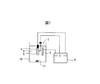
- the present embodiment will be described with reference to FIG. 1, taking as an example a method for evaluating fine particles in a steel material by a nonaqueous solvent-based constant potential electrolysis method (SPEED method), which is a general electrolytic extraction method.
- the extraction method in the present invention is not limited to the SPEED method.
- the metal sample 4 is processed into a size of, for example, 20 mm ⁇ 40 mm ⁇ 2 mm, and an oxide film such as a scale on the surface layer is removed by chemical polishing or mechanical polishing, and a metal layer is taken out. . Conversely, when analyzing the fine particles contained in the oxide film layer, it is left as it is.
- this metal sample is electrolyzed using the SPEED method.
- the electrolytic bath 9 is filled with the electrolytic solution 9, the metal sample 4 is immersed therein, and the reference electrode 7 is brought into contact with the metal sample 4.
- the platinum electrode 6 and the metal sample 4 are connected to the electrolysis device 8. By energizing between the metal sample 4 and the platinum electrode 6, the platinum electrode 6 can operate as a cathode.
- the electrolytic potential of fine particles in steel such as precipitates has a higher electrolytic potential than the electrolytic potential of the metal portion serving as the matrix of the metal sample 4.
- Electrolytic solution for metal material according to the present invention that is, to electrolyze the surface Fe matrix in order to observe inclusions and precipitated phases, or to electrolyze Fe matrix in order to quantitatively analyze inclusions and precipitated phases
- the electrolytic solution used for electrolysis to recover the residue is preferably (1) a complex-forming agent for Fe ions, (2) electrolyte for ensuring conductivity in the electrolyte, (3) a solvent for holding the formed complex such as Fe in the liquid, including.
- one or more kinds may be selected from acetylacetone, maleic anhydride, maleic acid, triethanolamine, salicylic acid, and methyl salicylate.
- TMAC tetramethylammonium chloride
- NaCl sodium chloride
- LiCl lithium chloride
- the solvent needs to be capable of holding various complex-forming agents and their complexes with Fe in a dissolved state, and may be a non-aqueous solvent.
- Aqueous electrolytes decompose various precipitates even at relatively low electrolysis voltages (eg -300 mV or less), whereas nonaqueous solvent electrolytes have a wide range of stable electrolysis, superalloys, high alloys, stainless steels. It can be applied to almost all steel materials from steel to carbon steel.
- a non-aqueous solvent-based electrolyte mainly the dissolution of the matrix and the (complexation) reaction between the dissolved Fe ions and the chelating agent only occur, and the inclusion or precipitated phase 5 does not dissolve, Three-dimensional observation and analysis can be performed in an “in situ” state on the base material.
- a compound that smoothly proceeds electrolysis and dissolves a complexable organic compound and a supporting electrolyte is suitable.
- a lower alcohol such as methanol, ethanol, or isopropyl alcohol is used.
- Methanol, ethanol, or a mixture thereof can be selected.
- an electrolytic solution for example, 10% by mass acetylacetone (hereinafter referred to as “AA”)-1% by mass tetramethylammonium chloride (hereinafter referred to as “TMAC”)-methanol solution, or 10% by mass Maleic anhydride-2 mass% TMAC-methanol solution is used.
- AA acetylacetone
- TMAC tetramethylammonium chloride
- metals other than the matrix (Fe) may be eluted although they are relatively small compared to the matrix (Fe).
- metal ions e.g.
- the double-lined frame (or dark gray frame) is a combination of sulfides having a pK sp difference ⁇ of 22 or more, and in these combinations, the exchange reaction is expected to proceed easily or in seconds. Is done. Expressed simply with symbols, the expectation (prediction) of the exchange reaction is expressed as ⁇ .
- a bold line frame is a combination of sulfides having a pK sp difference ⁇ of 10 or more and less than 22 and may take several minutes to several hours, but the exchange reaction is expected to proceed.
- the Expressed simply in symbols, the expectation (prediction) of the exchange reaction is expressed as ⁇ to ⁇ .
- the thin line frame (or white frame) is a combination of sulfides having a pK sp difference ⁇ of less than 10, and it is expected that the exchange reaction is unlikely to proceed with these combinations.
- the expected exchange rate is expressed as ⁇ ⁇ ⁇ .
- Table 1 lists sulfides having a crystal form or the like in which the difference ⁇ of pK sp is small. This may be in the form of the difference between the pK sp delta increases, the difference between the pK sp of the sulfide to be delta becomes 10 or more, she is considered that exchange reaction proceeds.
- the solubility product Ksp is a value in an aqueous solution, but it is presumed that the same tendency is observed even in non-aqueous solvents such as methanol of the same polar solvent.
- the Cu ion sulfide eluted in the electrolyte has an attack on MnS because the difference in pK sp from MnS is 22.6. Then, Mn is ionized and expelled into the electrolytic solution, and itself remains as CuS on the MnS surface. That is, inclusions and precipitated phases that originally existed as MnS in the Cu-containing steel sample are observed as CuS as long as the surface is observed.
- the upper left image is the SEM observation image
- the upper right image is the SEM observation image superimposed on the chart of Ag concentration measured by EDS
- the lower left image Is an overlay of Mn concentration charts
- the lower right image is an overlay of S concentration charts.
- Certain members comprise the 'metal (attack metal) M' metal compound M 'x' A y, wherein the metal compound M 'x' 'the solubility product K sp [M' A y x ' A y ' ]
- K sp [M x A y ] K sp [M x A y ]
- ⁇ pK sp [M ′ x ′ A y ′ ]
- ⁇ pK sp [M x A y ] ( ⁇ Log 10 K sp [M ′ x ′ A y ′ ]) ⁇ ( ⁇ log 10 K sp [M x A y ]) ⁇ 10 It is.
- M and M ′ are different metal elements
- A is a single atom or atomic group forming a compound with M or M ′
- x, x ′, y, and y ′ are M, M ′, and A, respectively.
- the solubility ratio Ksp is a value at 25 ° C. in an aqueous solution.
- metal ions other than the matrix (Fe) such as Cu may be dissolved by electrolysis, and such ions (for example, Cu ions) move to the cathode and precipitate. Since there is no trapping site after deposition, it can be easily peeled off from the cathode, and can be precipitated as metal Cu in the electrolytic solution or can be a source of attack metal M ′ (Cu, etc.). That is, it can be a contamination source of inclusions, precipitated phases, and electrolytic residues.
- the electrolytic etching apparatus of the present invention includes a member containing the attack metal M ′ in at least a part of the cathode. Since the member provided in a part of the cathode contains the attack metal M ′, it acts as a trapping site (precipitation site) for actively attaching the attack metal M ′ (Cu, etc.) ions. It is considered that the higher the content of the attack metal M ′ in the member, the higher the effect of the action of positively attaching the attack metal M ′ (Cu etc.) ions. Therefore, the content of the attack metal M ′ in the member may be 90% by mass or more, preferably 95% by mass or more, and more preferably 99% by mass or more.
- the attack metal M ′ and the attack metal M ′ included in the member provided in a part of the cathode are the same material, they have high affinity. Therefore, the attack metal M ′ ( Cu, etc.) can be prevented from peeling off after precipitation and precipitation as metal Cu. Further, the supply source of the attack metal M ′ (Cu or the like) into the electrolytic solution can be reduced. Therefore, even if the metal compound M x A y having a large difference ⁇ pK sp exists, the attack metal M ′ is replaced with the metal M on the surface of the metal compound M x A y (that is, Artifact). Can not be done freely. In other words, the generation of M ′ x ′ A y ′ is suppressed.
- the inclusions and precipitated phases in the steel sample for surface observation can be observed as they are,
- the electrolytic residue to be analyzed does not contain metal Cu, CuS, etc. derived from Cu ions dissolved from the matrix of the sample, etc., and originates from inclusions and precipitated phases originally contained in the steel sample. Only elements can be correctly identified and quantified.
- the metal M ′ of the metal compound M ′ x ′ A y ′ having a large pK sp may be at least one of Hg, Ag, Cu, Pb, Cd, Co, Zn, and Ni. These can be attack metals M ′.
- the attack metal M ′ is considered to be mainly the metal M ′ contained in the steel material sample or a compound thereof eluted in the electrolytic solution.
- the electrolytic solution and the electrolytic device may be reused, and the metal M ′ or a compound thereof may be present in the reused electrolytic solution or electrolytic device, and this may become the attack metal M ′. .
- the metal M ′ or a compound thereof may be mixed into the electrolytic solution as a contamination substance, and become an attack metal M ′.
- M ′ may be at least one of Hg, Ag, Cu, Pb, Cd, Co, Zn, and Ni, but is a metal element different from M.
- A is a single atom or atomic group forming a compound with M or M ′, and one or more atoms independently selected from the group consisting of C, N, H, S, O, P and F atoms May be included.
- the difference ⁇ p of pK sp between Hg, Ag, Cu, Pb, Cd, Co, Zn, and Ni sulfide and MnS is 10 or more.
- the difference ⁇ pK sp between Hg, Ag, Cu sulfide and MnS is 20 or more.
- the difference ⁇ pK sp between the extraction target metal compound MxAy and the attack metal compound M′x′Ay ′ is about 10
- Artifact can occur in several hours. Actual electrolytic extraction analysis is often performed on the order of several hours. Therefore, a combination having a difference ⁇ p p sp of about 10 may affect the analysis.
- the difference ⁇ pk sp is defined as 10 or more, and Artifact that can occur in that case can be suppressed.
- Artifact can be easily or quickly generated as the difference ⁇ in pK sp between the extraction target metal compound MxAy and the attack metal compound M′x′Ay ′ increases.
- M'x'Ay 'pK sp [M'x'Ay of'] is compared to the pK sp [MxAy] to be extracted metal compound MxAy, it may be preferable 11 or more large, large 12 or more More preferably, it is more preferably 13 or more, more preferably 14 or more, more preferably 15 or more, still more preferably 16 or more, further preferably 17 or more, further preferably 18 or more.
- 19 or more is more preferable, 20 or more is more preferable, 21 or more is preferable, 22 or more is more preferable, 22 or more is more preferable, 23 or more is more preferable, 24 or more is more preferable, 25 More preferably larger, more preferably 26 or larger.
- 27 or more is more preferable, 28 or more is more preferable, 29 or more is more preferable, 30 or more is more preferable, 31 or more is preferable, 31 or more is more preferable, 32 or more is more preferable, More preferably 33 or more, more preferably 34 or more, still more preferably 35 or more, still more preferably 36 or more, still more preferably 37 or more, still more preferably 38 or more, and 39 or more. More preferably, it is more preferably 40 or more.
- the solubility product K sp is the value of the aqueous solution, as shown in Table 2, the difference between the non-aqueous solvent is obtained from K sp even when a (lower alcohol) pK sp (-log 10 K sp ) ⁇ Is 10 or more, and it has been confirmed that a reaction is observed. Specifically, the following confirmation test was conducted. -As a sample containing the extraction object, two kinds of steel materials containing MnS (MnS having a particle size of 1 ⁇ m or more and those having a particle size of 100 to 150 nm) were prepared, and their surfaces were mirror-polished. .
- M '+ solutions standard solutions for atomic absorption analysis (M '+ solutions) with the metal ion concentrations of Ag, Cu, Pb, Co, Zn, and Ni being 1000 ⁇ g / ml were prepared as attack metal M ′ + ions.
- M ′ solution was mixed with 0.3 ml of methanol which is a non-aqueous solvent.
- the liquid mixture was applied to the steel material surface, and the change of the steel material surface was confirmed.
- the mixed solution containing Ag and Cu the surface of the steel material changed to black within 5 minutes from the application.
- the mixed liquid containing Pb the surface of the steel material changed to black in about 10 minutes after the application.
- the surface of the steel material changed to black in about 20 minutes after the application. Furthermore, when SEM and EDS observations were performed on the discolored steel material, it was confirmed that substitution of Mn and attack metal M ′ (that is, Artifact) occurred on the surface of the MnS particles. It was. Therefore, in the scope of the present invention, the solubility product Ksp is an indicator in an aqueous solution, but it can be applied to a non-aqueous solution, and the solubility product Ksp there shows the same tendency as in an aqueous solution. Is estimated. It was also confirmed that the substitution (Artifact) reaction was faster as the difference ⁇ of pK sp was larger.
- a member including the attack metal M ′ provided in the cathode may be provided so as to cover the surface of the cathode. This is because the surface of the cathode acts as a trapping site for attack metal M ′ ions, and the effect of suppressing separation / precipitation after deposition of the deposited attack metal M ′ (Cu, etc.) is enhanced.
- the cathode may be made of a metal of a metal compound having the small solubility product K sp (large pK sp ).
- the whole of the cathode is made of the attack metal M ′, the affinity with the attack metal M ′ ion is further increased, it acts more effectively as a trapping site for the attack metal M ′ ion, and the deposited attack metal M ′ (Cu This is because the effect of suppressing exfoliation / precipitation after the deposition of the above is further enhanced.
- the member made of the attack metal M ′ provided in the cathode may be made of 99.9% or more of Cu and inevitable impurities by mass%. As described above, Cu is prominent as the attack metal M ′ that easily causes Artifact. By making the member made of the attack metal M ′ composed of 99.9% or more of Cu and unavoidable impurities by mass%, the effect of suppressing the exfoliation and precipitation of Cu as the attack metal M ′ is surely high. can do.
- Crown ether can be used as an agent for forming a complex containing an attack metal M ′.
- Crown ether is a cyclic polyether (with several ether units connected), and the size of the annular hole can be changed. Therefore, a crown ether having an appropriate hole can be prepared in accordance with the attack metal species M ′, whereby only the attack metal species M ′ can be selectively captured.
- medical agent which forms the complex containing attack metal M ' may contain any 1 type, or 2 or more types in polyethyleneamines, ethylenediaminetetraacetic acid, and cyclohexanediamine 4 acetic acid. These act as chelating agents and capture the attack metal M ′.
- polyethyleneamines include triethylenetetramine (TETA), penicillamine, and pentaethylenehexamine.
- TETA triethylenetetramine
- a chelating agent such as triethylenetetramine has high selectivity for Cu ions and Ni ions, and a particularly high trapping effect is exhibited when the attack metal M ′ is Cu or Ni.
- Table 3 shows the stability constant (Log 10 K d ) of the complex when Cu or Ni as the attack metal M ′ is captured by various chelating agents. A higher stability constant is preferable because it is considered that the attack metal is not easily captured and released again.
- the agent that forms a complex containing the attack metal M ′ has a stability constant of 10 or more, preferably 12 or more, more preferably 14 Those above, more preferably 16 or more, further preferably 18 or more, and more preferably 20 or more may be selected.
- the attack metal M ′ is captured and a complex of the attack metal M ′ is formed.
- the attack metal M ′ complex is retained in a dissolved state in the above-described solvent. Therefore, even if the metal compound M x A y having a large difference ⁇ pK sp exists, the attack metal M ′ is replaced with the metal M on the surface of the metal compound M x A y (that is, Artifact). Can not be done freely. In other words, the generation of M ′ x ′ A y ′ is suppressed.
- medical agent which forms a complex, or the electrolyte solution containing this may be stirred in an electrolytic vessel.
- the stirring means is not particularly limited, and bubbling by a bubble generator, vortex flow by a magnetic stirrer, or the like may be used.
- an unreacted drug droplet may be dropped in the vicinity of the attack metal M ′.
- the lower limit may be 100 cc / min for bubbling, preferably 200 cc / min for bubbling, and 100 rpm, preferably 200 rpm for a stirrer, so that unreacted drug easily contacts the attack metal M ′.
- the upper limit may be 600 cc / min, preferably 500 cc / min for bubbling, and 600 rpm, preferably 500 rpm for a stirrer.
- the stirring operation is performed so that the flow of the electrolytic solution generated by the stirring does not contact the object to be electrolyzed. This is based on the idea that the flow of the electrolyte generated by stirring does not affect the object to be electrolyzed.
- the drug is stirred or supplied so that the flow of the electrolytic solution generated by stirring or the like comes into contact with the object to be electrolyzed.
- gas for bubbling inert gas, such as nitrogen gas, helium, and argon, is mentioned.
- Active gases such as oxygen and hydrogen are not preferred because they may affect the dissolved oxygen concentration in the electrolyte and may affect the object to be electrolyzed.
- the present invention there is also provided a method for extracting metal compound particles in a metal material using the same action as the above-described electrolytic etching apparatus.
- the method relates to a method in which an anode and a cathode are provided, a metal material is electrolytically etched by energization between the anode and the cathode, and metal compound particles in the metal material are extracted.
- the extracted metal fine particles the actual state of MnS and FeS fine particles is not mistaken for CuS, and the true shape (size, component) of the metal sulfide can be known. It is also possible to accurately grasp the content of metal sulfide.
- the extract for example, inclusions or precipitated phases exposed on the surface of the steel sheet sample by electrolysis
- the quantitative analysis can be performed correctly without being affected by Cu mixed in from the electrolytic solution. This greatly contributes to improving the accuracy of structural observation and identification / quantitative analysis of inclusions or precipitated phases in steel samples.
- Mn of the precipitate MnS can be easily substituted with Se in the steel material, and can be precipitated as MnSe. This is because MnS and MnSe have the same NaCl type structure, and the lattice constant is extremely high. It is said that it is close. From the element periodic rule, it is expected that Te, which is the same group as S and Se, and Sb of the adjacent group are also easily replaced with S of MnS and precipitated as MnTe or MnSb. And if MnS is easily substituted with MnSe, MnTe and / or MnSb, correct quantitative analysis of MnS is considered to be useful for improving accuracy of quantitative analysis of MnSe, MnTe and MnSb.
- MnSe generated by MnS substitution or the like may cause further substitution (Artifact reaction) with other selenides.
- the bold line frame (or light gray frame) is the difference in pK sp This is a combination of selenides having ⁇ of 10 or more and less than 22.
- the exchange reaction is expected to take several minutes to several hours, but the exchange reaction is expected to proceed. (Prediction) is expressed as ⁇ ⁇ ⁇ .
- Thin line frame (or white frame) is a combination of selenide difference pK sp delta is less than 10, the exchange reaction is a combination thereof and hardly proceeds Expressed simply with symbols, the expectation (prediction) of the exchange reaction is expressed as ⁇ ⁇ ⁇ .
- Artifact can also be prevented for selenides.
- Quantitative analysis of inclusions or precipitated phases in steel samples was performed by electrolysis using the electrolytic etching apparatus according to the present invention.
- a comparative example in which electrolysis was performed using a conventional electrolytic solution was prepared.
- a steel material containing 0.4% by mass of Cu as a steel sample was subjected to a heat treatment at 1350 ° C. ⁇ 30 min, and then rapidly cooled in water.
- the following two types of electrolyte solutions were prepared.
- TMAC tetramethylammonium chloride
- TMAC tetramethylammonium chloride
- SPEED tetramethylammonium chloride
- (2) 4% MS + 5% TETA: 5% by volume of triethylenetetramine (TETA) that forms a complex with Cu ions is added to 4% MS of (1).
- the solvent was methanol in
- the sample on the cathode side was made of Pt and the case where the Cu plate was fixed to the Pt plate was electrolyzed with about 1 g of the sample, and included in the obtained electrolytic residue.
- the contents of Mn and Cu were quantified by wet chemical analysis, and the contents contained in a 1 g steel material sample were calculated.
- the method of fixing the Cu plate to the Pt plate was as follows. Cu plates to be fixed are prepared in the same size as Pt plates, both plates are overlapped, holes are made in the ends of both plates, Pt wires are passed through the holes, and both plates are fixed with Pt wires. (Bundled).
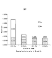
- the four band graphs show Mn and Cu detected from the electrolytic residue in percent units, and from the left, (1) General electrolyte (4% MS) Then, when electrolysis was performed using the Pt electrode as a cathode, (2) when electrolysis was performed with a Cu plate fixed to the cathode with a general electrolyte solution (4% MS), and (3) the volume of TETA was 5 volumes. % Electrolyte solution (4% MS + 5% TETA) and a Pt electrode on the cathode side, (4) Electrolyte solution containing 5% by volume of TETA (4% MS + 5% TETA) ) And a case where electrolysis is performed with a Cu plate fixed to the cathode.
- 4% MS General electrolyte
- the graph shown in (2) is a case where a Cu plate is fixed to a Pt-made cathode and electrolysis is performed with an electrolytic solution (4% MS).
- the Cu component in the electrolytic residue is 0.0103 mass% (103 ppm). It has decreased to. This is because the Cu plate fixed to the Pt cathode acts as an attack metal (Cu) ion trapping site (precipitation site), and suppresses exfoliation and precipitation after the deposition of the attack metal (Cu) electrolytically deposited at the cathode. As a result, it is considered that the metal Cu that precipitates in the residue and the attack metal (Cu) supply source into the electrolyte are reduced.
- the graph shown in (3) shows that Mn measured from the electrolytic residue obtained by electrolysis with an electrolytic solution (4% MS + 5% TETA) added with 5% by volume of triethylenetetramine while the cathode remains the Pt electrode.
- the concentration of Cu is shown.
- the Cu component in the electrolytic residue is reduced to 0.0016% by mass (16 ppm).
- TETA triethylenetetramine
- Au attack metal
- MnS metal compound
- Electrode cathode side
- Reference electrode Reference electrode
- Power supply potentiostat
- Electrolytic solution 10
- Electrolytic tank 11 Electrolytic residue
Abstract
Description
従って、介在物及び/又は析出相の観察や、その成分、分量を測定することは鉄鋼材料の品質管理や製造プロセスの解析を行う上で、重要な意味を持つ。 Metal materials, especially steel materials, are required for steel materials by controlling the shape, dimensions, etc. of inclusions, types of precipitated phases, aspect ratio, etc. present in the material matrix by using trace additive elements and various heat treatments. Controlling strength and properties is widely practiced.
Therefore, observation of inclusions and / or precipitated phases and measurement of their components and quantities are important in conducting quality control of steel materials and analysis of manufacturing processes.
この電解液組成物は、従来の電解液が酸性のものが多かったのに対して、アルカリ性のトリエタノールアミンが添加されていることにより、微細な介在物や析出相であっても、溶解され難くなり、これらの介在物や析出物の粒子が鋼材試料表面に残留し易く、鉄鋼試料を電解液から取り出し乾燥後、そのままの状態でSEM等による観察や分析を可能としている。
In contrast to many conventional electrolytes that are acidic, this electrolyte composition dissolves even fine inclusions and precipitated phases due to the addition of alkaline triethanolamine. These inclusions and precipitate particles are likely to remain on the surface of the steel material sample, and the steel sample is taken out of the electrolytic solution and dried, and can be observed and analyzed by SEM or the like as it is.
この電解液は、無水マレイン酸と、塩化テトラメチルアンモニウムと、メタノールを所定の割合で含むものであり、一度に大量の鉄鋼試料を電解する能力に優れた電解液であり、液中に含まれる無水マレイン酸が、鉄錯体を生成し、Fe水酸化物等の錯体沈殿生成を阻止する特徴を有する。 Further,
This electrolytic solution contains maleic anhydride, tetramethylammonium chloride, and methanol in a predetermined ratio, and is an electrolytic solution excellent in the ability to electrolyze a large amount of steel samples at a time, and is included in the solution. Maleic anhydride has the characteristic of forming an iron complex and preventing complex precipitation such as Fe hydroxide.
一方、介在物や析出相の定量分析であれば、マトリックスのFe分をキレート剤によって電解液中に保持し、電解によって試料から離脱した介在物や析出相を溶解しないような電解液を用いて、これらを電解残渣として回収し、該残渣を同定・定量分析する。
したがって、介在物や析出相の同定・定量分析のための残渣回収を目的とする場合、Fe分を電解液中にキレート錯体として溶解状態を維持できることに主眼が置かれており、電解操作中での介在物や析出相に対するコンタミネーションなどについては、特段の配慮がなされていなかった。 In order to observe inclusions and precipitated phases in steel samples in situ with an SEM or the like, the sample is electrolyzed, and Fe components constituting the matrix are held in an electrolyte solution with an Fe ion chelating agent. Electrolysis is performed so that the deposited phase remains on the sample surface.
On the other hand, for quantitative analysis of inclusions and precipitated phases, use an electrolyte solution that retains the Fe content of the matrix in the electrolyte solution with a chelating agent and does not dissolve the inclusions and precipitated phase that have been detached from the sample by electrolysis. These are recovered as electrolytic residues, and the residues are identified and quantitatively analyzed.
Therefore, when aiming at residue collection for the identification and quantitative analysis of inclusions and precipitated phases, the main focus is on maintaining the dissolved state as a chelate complex in the electrolyte solution. No particular consideration has been given to the inclusions and contamination of the precipitated phase.
ことで、残渣から質量分析を行っても、微細粒子の場合には、体積の相当部分をCuSが占めることとなるので、正確な定量が不可能となっていた。 As a result, inclusions and precipitated phases originally present as MnS in steel samples are observed as CuS as long as the surface is observed, and Cu ions in the electrolytic solution are also present on the surface of MnS. By replacing CuS due to slag with MnS with a thickness of about several tens of nanometers (1 to 100 nm), CuS occupies a considerable part of the volume in the case of fine particles even if mass analysis is performed from the residue. Therefore, accurate quantification has been impossible.
上記の条件は、以下の式で表すことができる。
Δ=pKsp[化合物(Kspの小さいもの)]-pKsp[化合物(Kspの大きいもの)]
=(-log10Ksp[化合物(Kspの小さいもの)])-(-log10Ksp[化合物(Kspの大きいもの)])
≧10
ここで、或る化合物の溶解度積KspはKsp[化合物]と表し、pKsp[化合物]=-log10Ksp[化合物]と表す。 In the above description, the case of attack on the MnS surface by Cu (substitution phenomenon of Mn atoms and Cu atoms on the MnS surface) has been described. However, it can be estimated that the same phenomenon occurs in metals other than Cu. That is, the substitution of metal ions on the surface metal compound, solubility magnitude difference corresponds to the product K sp when there is (10 digits (10 10) of about or more magnitude difference), can be estimated to proceed easily. (Hereinafter, this phenomenon is referred to as “Artifact” in this specification). More specifically, when the difference in pK sp between two compounds having different solubility products K sp (hereinafter sometimes referred to as Δ) is about 10 or more, a compound having a large pK sp (small solubility product K sp ) and pK It can be presumed that substitution with a compound having a small sp (high solubility product) proceeds easily.
The above conditions can be expressed by the following formula.
Δ = pK sp [compound (small K sp )] − pK sp [compound (large K sp )]
= (-Log 10 K sp [compound (small K sp )]]-(-log 10 K sp [compound (large K sp )]])
≧ 10
Here, the solubility product K sp of a certain compound is expressed as K sp [compound], and is expressed as pK sp [compound] = − log 10 K sp [compound].
Δ=pKsp[Ag2S]-pKsp[MnS]
=50.1-13.5
=36.6≧10 Indeed, the present inventors have conducted simulations to act Ag in MnS, Ag is to attack the MnS, together expel the ionized in the electrolytic solution Mn, itself, Ag 2 S in MnS surface It was confirmed that it remained as Here, when the solubility product (or pK sp ) of Ag 2 S and MnS is compared, the solubility product K sp of Ag 2 S is small (pK sp is large), and the solubility product K sp of MnS is large (pK sp is small). ). The difference in solubility product K sp between Ag 2 S and MnS is 37 digits, and the difference Δ in pK sp is 36.6. This is expressed by the following formula.
Δ = pK sp [Ag 2 S] −pK sp [MnS]
= 50.1-13.5
= 36.6 ≧ 10
・溶媒系電解液での電解腐食法等による金属材料中の金属微粒子(介在物、析出物)の抽出や分析において、従来の抽出・分析方法を大きく変更することなく、Cuイオン等による金属微粒子の表面置換を抑制し、Artifact(擬制)CuS等の生成を防止することを課題とする。
・特に金属硫化物(MnS、FeS等)に着目し、Artifact(擬制)CuS等の生成を防止することを課題とする。
・陰極上に析出したCu等の金属が容易に剥離・沈殿して、介在物や析出相および電解残渣のコンタミネーション源とならないように、陰極上に積極的に付着させることを課題とする。 Therefore, the problems to be solved by the present invention are as follows.
-In the extraction and analysis of metal fine particles (inclusions, precipitates) in metal materials by electrolytic corrosion method with solvent electrolyte etc., metal fine particles by Cu ions etc. without greatly changing the conventional extraction / analysis method It is an object of the present invention to suppress the surface substitution of and prevent the generation of Artifact CuS and the like.
-Focus on metal sulfides (MnS, FeS, etc.) in particular, and prevent the generation of Artifact (pseudo) CuS, etc.
It is an object to positively adhere to a cathode so that a metal such as Cu deposited on the cathode does not easily peel and precipitate and become a source of contamination of inclusions, deposited phases and electrolytic residues.
その結果、溶媒系電解液中に、Artifact(擬制)金属硫化物を形成する金属(アタック金属)を存在させなければ、置換現象は発現しないという知見から、そのようなアタック金属を補足することに想い至った。すなわち、電解装置の陰極の少なくとも一部に、補足したい金属元素からなる部材を設置し、当該金属を陰極上に電解析出し易くし、析出したアタック金属を陰極上に保持することにより、電解液中の自由なアタック金属が減少し、Artifact(擬制)金属硫化物が生成されないことに想到した。 The inventors of the present application diligently studied a method for solving the above problems.
As a result, from the knowledge that the substitution phenomenon does not occur unless the metal (attack metal) that forms Artifact metal sulfide is present in the solvent-based electrolyte, the attack metal is supplemented. I thought. That is, by installing a member made of a metal element to be supplemented on at least a part of the cathode of the electrolysis apparatus, making the metal easy to be electrolytically deposited on the cathode, and holding the deposited attack metal on the cathode, It was conceived that the free attack metal in the inside decreased and no Artifact metal sulfide was produced.
(1)陽極と陰極を備え、陽極と陰極の間に通電することにより金属材料を電解エッチングし、金属材料中の金属化合物粒子を分離抽出する電解エッチング用装置であって、
金属化合物M’x’Ay’の溶解度積をKsp[M’x’Ay’] とし、
前記金属材料中に含まれる抽出対象金属化合物MxAyの溶解度積をKsp[MxAy] とすると、
下記式で定義されるΔが10以上となる金属M’が含まれる部材を、前記陰極の少なくとも一部に備え、
前記金属M’を含む錯体を形成する薬剤及び非水溶媒を含む電解液を収容する電解槽を備えることを特徴とする、電解エッチング用装置。
Δ=pKsp[M’x’Ay’]-pKsp[MxAy]
=(-log10Ksp[M’x’Ay’])-(-log10Ksp[MxAy])
ここで、MとM’は異なる金属元素であり、AはMまたはM’と化合物を形成する単原子または原子団であり、x、x’、y、y’はM、M’、Aの価数に応じて決まる前記化合物の組成比を表し、前記溶解度積Kspは水溶液中25℃での値である
This invention is made | formed based on the said knowledge, The summary is as follows.
(1) An apparatus for electrolytic etching comprising an anode and a cathode, electrolytically etching a metal material by energizing between the anode and the cathode, and separating and extracting metal compound particles in the metal material,
The solubility product of the metal compound M ′ x ′ A y ′ is K sp [M ′ x ′ A y ′ ],
When the solubility product of the extraction target metal compound M x A y contained in the metal material is K sp [M x A y ],
A member including a metal M ′ having a Δ defined by the following formula of 10 or more is provided in at least a part of the cathode,
An apparatus for electrolytic etching, comprising: an electrolytic cell containing an electrolytic solution containing a drug that forms a complex containing the metal M ′ and a nonaqueous solvent.
Δ = pK sp [M ′ x ′ A y ′ ] −pK sp [M x A y ]
= (− Log 10 K sp [M ′ x ′ A y ′ ]) − (− log 10 K sp [M x A y ])
Here, M and M ′ are different metal elements, A is a single atom or atomic group forming a compound with M or M ′, and x, x ′, y, and y ′ are M, M ′, and A It represents the composition ratio of the compound determined according to the valence, and the solubility product Ksp is a value at 25 ° C. in an aqueous solution.
(7)前記非水溶媒が、メタノールまたはエタノールの少なくとも一つを含んでなることを特徴とする(1)~(6)のいずれかに記載の電解エッチング装置。
(8)前記金属M’を含む錯体を形成する薬剤が、ポリエチレンアミン類、エチレンジアミン4酢酸、シクロヘキサンジアミン4酢酸の少なくとも一つを含んでなることを特徴とする(1)~(7)のいずれかに記載の電解エッチング装置。
(9)前記薬剤がトリエチレンテトラミンを含んでなることを特徴とする、(8)に記載の電解エッチング装置。
(10)電解液の撹拌手段をさらに備える(1)~(9)のいずれかに記載の電解エッチング装置。
(11)前記陽極表面に気泡を照射する気泡発生器を、さらに備える(10)に記載の電解エッチング装置。
(6) The apparatus for electrolytic etching as described in any one of (1) to (5) above, wherein the member provided in the cathode is composed of 99.9% or more of Cu and unavoidable impurities by mass%. .
(7) The electrolytic etching apparatus according to any one of (1) to (6), wherein the non-aqueous solvent contains at least one of methanol and ethanol.
(8) The agent for forming a complex containing the metal M ′ comprises at least one of polyethyleneamines, ethylenediaminetetraacetic acid, and cyclohexanediaminetetraacetic acid. An electrolytic etching apparatus according to
(9) The electrolytic etching apparatus according to (8), wherein the chemical agent comprises triethylenetetramine.
(10) The electrolytic etching apparatus according to any one of (1) to (9), further comprising a stirring means for the electrolytic solution.
(11) The electrolytic etching apparatus according to (10), further including a bubble generator that irradiates the anode surface with bubbles.
金属化合物M’x’Ay’の溶解度積をKsp[M’x’Ay’] とし、
前記金属材料中に含まれる抽出対象金属化合物MxAyの溶解度積をKsp[MxAy] とすると、
下記式で定義されるΔが10以上となる金属M’が含まれる部材を、前記陰極の表面の少なくとも一部に備え、
前記金属M’を含む錯体を形成する薬剤及び非水溶媒を含む電解液を用いることを特徴とする、金属化合物粒子の抽出方法。
Δ=pKsp[M’x’Ay’]-pKsp[MxAy]
=(-log10Ksp[M’x’Ay’])-(-log10Ksp[MxAy])
ここでMとM’は異なる金属元素であり、AはMまたはM’と化合物を形成する単原子または原子団であり、x、x’、y、y’はM、M’、Aの価数に応じて決まる前記化合物の組成比を表し、前記溶解度積Kspは水溶液中25℃での値である
(13)前記電解エッチングを行う際に、電解液を撹拌しながら電解エッチングすることを特徴とする(12)に記載の金属化合物粒子の抽出方法。
(14)電解液をマグネチックスターラーで撹拌することを特徴とする(13)に記載の金属化合物粒子の抽出方法。
(15)電解液中に気泡をバブリングすることを特徴とする(13)に記載の金属化合物粒子の抽出方法。 (12) In a method comprising an anode and a cathode, the metal material is electrolytically etched by energization between the anode and the cathode, and the metal compound particles in the metal material are extracted.
The solubility product of the metal compound M ′ x ′ A y ′ is K sp [M ′ x ′ A y ′ ],
When the solubility product of the extraction target metal compound M x A y contained in the metal material is K sp [M x A y ],
A member containing a metal M ′ having a Δ defined by the following formula of 10 or more is provided on at least a part of the surface of the cathode,
A method for extracting metal compound particles, wherein an electrolyte containing a drug that forms a complex containing the metal M ′ and a non-aqueous solvent is used.
Δ = pK sp [M ′ x ′ A y ′ ] −pK sp [M x A y ]
= (− Log 10 K sp [M ′ x ′ A y ′ ]) − (− log 10 K sp [M x A y ])
Here, M and M ′ are different metal elements, A is a single atom or atomic group forming a compound with M or M ′, and x, x ′, y, and y ′ are valences of M, M ′, and A, respectively. It represents the composition ratio of the compound determined according to the number, and the solubility product Ksp is a value at 25 ° C. in an aqueous solution.
(13) The method for extracting metal compound particles according to (12), wherein the electrolytic etching is performed while stirring the electrolytic solution when the electrolytic etching is performed.
(14) The method for extracting metal compound particles according to (13), wherein the electrolytic solution is stirred with a magnetic stirrer.
(15) The method for extracting metal compound particles according to (13), wherein bubbles are bubbled in the electrolytic solution.
・本願発明によれば、電解操作によって鋼板試料表面に露出させた介在物或いは析出相等を鉄鋼試料中に本来存在していた成分及び形態で観察することが可能となる他、電解残渣の分析から介在物や析出相成分を定量分析する場合に、電解液から混入するCu等の影響を受けずに、正しく定量分析することができるので、鉄鋼試料の組織観察や、鉄鋼試料中の介在物或いは析出相の同定・定量分析の精度向上におおいに寄与するものである。 ・ According to the present invention, the surface analysis of the extracted metal fine particles prevents the fact that the actual particles are MnS and FeS from being misidentified as CuS, and the true shape (size, component) of the metal sulfide can be known. Furthermore, it is possible to accurately grasp the content of metal sulfide in the steel material.
-According to the present invention, it becomes possible to observe inclusions or precipitated phases exposed on the surface of a steel sheet sample by electrolytic operation in the components and form originally present in the steel sample, and from analysis of electrolytic residue When quantitatively analyzing inclusions and precipitated phase components, it is possible to correctly perform quantitative analysis without being affected by Cu or the like mixed from the electrolytic solution, so that the structure observation of the steel sample, inclusions in the steel sample or This greatly contributes to improving the accuracy of identification and quantitative analysis of the precipitated phase.
金属化合物M’x’Ay’の溶解度積をKsp[M’x’Ay’] とし、
前記金属材料中に含まれる抽出対象金属化合物MxAyの溶解度積をKsp[MxAy] とすると、
下記式で定義されるΔが10以上となる金属M’が含まれる部材を、前記陰極の少なくとも一部に備え、
前記金属M’を含む錯体を形成する薬剤及び非水溶媒を含む電解液を収容する電解槽を備えることを特徴とする、電解エッチング用装置が提供される。
Δ=pKsp[M’x’Ay’]-pKsp[MxAy]
=(-log10Ksp[M’x’Ay’])-(-log10Ksp[MxAy])
ここで、MとM’は異なる金属元素であり、AはMまたはM’と化合物を形成する単原子または原子団であり、x、x’、y、y’はM、M’、Aの価数に応じて決まる前記化合物の組成比を表し、前記溶解度積Kspは水溶液中25℃での値である
According to the present invention, there is provided an apparatus for electrolytic etching comprising an anode and a cathode, electrolytically etching a metal material by energizing between the anode and the cathode, and separating and extracting metal compound particles in the metal material,
The solubility product of the metal compound M ′ x ′ A y ′ is K sp [M ′ x ′ A y ′ ],
When the solubility product of the extraction target metal compound M x A y contained in the metal material is K sp [M x A y ],
A member including a metal M ′ having a Δ defined by the following formula of 10 or more is provided in at least a part of the cathode,
An electrolytic etching apparatus is provided, comprising an electrolytic cell containing an electrolytic solution containing a drug that forms a complex containing the metal M ′ and a nonaqueous solvent.
Δ = pK sp [M ′ x ′ A y ′ ] −pK sp [M x A y ]
= (− Log 10 K sp [M ′ x ′ A y ′ ]) − (− log 10 K sp [M x A y ])
Here, M and M ′ are different metal elements, A is a single atom or atomic group forming a compound with M or M ′, and x, x ′, y, and y ′ are M, M ′, and A It represents the composition ratio of the compound determined according to the valence, and the solubility product Ksp is a value at 25 ° C. in an aqueous solution.
金属試料中の微粒子の抽出方法としては、例えば、酸溶液中で鉄鋼試料の鉄マトリックスを溶解する酸分解法、ヨウ素メタノール混合溶液あるいは臭素メタノール混合溶液中で鉄鋼試料の鉄マトリックスを溶解するハロゲン溶解法、非水溶媒系定電流電解法、又は、非水溶媒系定電位電解(SPEED:Selective Potentiostatic Etching by Electrolytic Dissolution Method)法等を用いることができる。これらの内、非水溶媒を用いるSPEED法は、溶媒中に微粒子が分散された際に、組成やサイズの変化が起こり難く、不安定な微粒子でも安定的に抽出できるため好適である。本実施形態に関して、図1を参照しながら、一般的な電解抽出法である非水溶媒系定電位電解法(SPEED法)による鉄鋼材料中の微粒子の評価方法を例に取り、説明を行うが、本発明における抽出の方法はSPEED法に限定されるものではない。 In the apparatus for electrolytic etching of the present invention, metal compound particles in a metal material are extracted. That is, by etching the metal material in the electrolyte solution, the matrix (Fe or the like) is selectively dissolved to expose the metal compound particles such as inclusions and precipitated phases contained in the metal material on the sample surface. As a result, the metal compound particles can be observed.
Examples of the method for extracting fine particles in a metal sample include an acid decomposition method in which an iron matrix of a steel sample is dissolved in an acid solution, a halogen dissolution in which an iron matrix of a steel sample is dissolved in an iodine methanol mixed solution or a bromine methanol mixed solution. A nonaqueous solvent system constant current electrolysis method, a nonaqueous solvent system constant potential electrolysis (SPEED) method, or the like. Among these, the SPEED method using a non-aqueous solvent is preferable because the composition and size hardly change when the fine particles are dispersed in the solvent, and even unstable fine particles can be stably extracted. The present embodiment will be described with reference to FIG. 1, taking as an example a method for evaluating fine particles in a steel material by a nonaqueous solvent-based constant potential electrolysis method (SPEED method), which is a general electrolytic extraction method. The extraction method in the present invention is not limited to the SPEED method.
(1)Feイオンに対する錯体形成剤、
(2)電解液に導電性を担保させる為の電解質、
(3)形成されたFe等の錯体を液中に保持するための溶媒、
を含む。 Electrolytic solution for metal material according to the present invention, that is, to electrolyze the surface Fe matrix in order to observe inclusions and precipitated phases, or to electrolyze Fe matrix in order to quantitatively analyze inclusions and precipitated phases, The electrolytic solution used for electrolysis to recover the residue is preferably
(1) a complex-forming agent for Fe ions,
(2) electrolyte for ensuring conductivity in the electrolyte,
(3) a solvent for holding the formed complex such as Fe in the liquid,
including.
なお、硫化物の溶解度積に関して、同じ元素の硫化物であっても結晶形態等によって、異なる溶解度積を示すものがある。表1では、pKspの差Δが小さくなる結晶形態等を有する硫化物を列記している。これは、pKspの差Δが大きくなる形態であっても、対象となる硫化物とのpKspの差Δが10以上となり、交換反応が進行すると考えられるからである。 Table 1 shows the solubility product K sp sulfide at 25 ° C. in an aqueous solution, the difference Δ of the pK sp (= -log 10 K sp ) between sulfides. In the table, the double-lined frame (or dark gray frame) is a combination of sulfides having a pK sp difference Δ of 22 or more, and in these combinations, the exchange reaction is expected to proceed easily or in seconds. Is done. Expressed simply with symbols, the expectation (prediction) of the exchange reaction is expressed as ◎. A bold line frame (or light gray frame) is a combination of sulfides having a pK sp difference Δ of 10 or more and less than 22 and may take several minutes to several hours, but the exchange reaction is expected to proceed. The Expressed simply in symbols, the expectation (prediction) of the exchange reaction is expressed as ○ to △. The thin line frame (or white frame) is a combination of sulfides having a pK sp difference Δ of less than 10, and it is expected that the exchange reaction is unlikely to proceed with these combinations. Expressed simply in symbols, the expected exchange rate (prediction) is expressed as Δ˜ ×.
Regarding the solubility products of sulfides, some sulfides of the same element show different solubility products depending on the crystal form and the like. Table 1 lists sulfides having a crystal form or the like in which the difference Δ of pK sp is small. This may be in the form of the difference between the pK sp delta increases, the difference between the pK sp of the sulfide to be delta becomes 10 or more, she is considered that exchange reaction proceeds.

・MnSを介在物として含んでいることを確認済の鉄鋼試料を用意し、表面不純物を除くために、予め鏡面研磨を施す。
・従来から知られている硫化物系介在物を残渣として回収できる4質量%サリチル酸メチル+1質量%サリチル酸+1質量%塩化テトラメチルアンモニウム(TMAC)を含み、溶媒がメタノールである電解液(4%MS)を用意する。
・前記鉄鋼試料を前記電解液中で電解を行う。
・電解終了後に、Agイオン溶液を前記電解液中に滴下し混合する。
・Agイオン溶液滴下する前と後で、表面を電解した鉄鋼試料について、走査電子顕微鏡(SEM)による観察および、EDSによる表面元素濃度の計測を行う。
・図3は、Agイオン滴下後のものであり、左上画像はSEM観察像であり、右上画像がSEM観察像に、EDSにより計測したAg濃度のチャートを重ねて示したものであり、左下画像がMn濃度のチャートを重ねて示したものであり、右下画像がS濃度のチャートを重ねて示したものである。
・なお、当然のことながら、Agイオン滴下前では、Agの存在は認められなかった。 Moreover, since the difference ΔpK sp of MnS is 36.6, Ag ion sulfide attacks on MnS, ionizes Mn and expels it into the electrolytic solution, and also forms Ag on the surface of MnS. It remains as 2S. This is confirmed in FIG. 3 obtained by the following procedure.
-Prepare a steel sample that has been confirmed to contain MnS as inclusions, and perform mirror polishing in advance to remove surface impurities.
-Electrolyte containing 4% by mass methyl salicylate + 1% by mass salicylic acid + 1% by mass tetramethylammonium chloride (TMAC) capable of recovering conventionally known sulfide inclusions as a residue, and the solvent is methanol (4% MS ).
-The steel sample is electrolyzed in the electrolytic solution.
-After completion of electrolysis, an Ag ion solution is dropped into the electrolyte and mixed.
-Before and after dropping the Ag ion solution, the steel sample whose surface is electrolyzed is observed with a scanning electron microscope (SEM) and the surface element concentration is measured with EDS.
FIG. 3 is after Ag ion dropping, the upper left image is the SEM observation image, the upper right image is the SEM observation image superimposed on the chart of Ag concentration measured by EDS, and the lower left image Is an overlay of Mn concentration charts, and the lower right image is an overlay of S concentration charts.
-As a matter of course, the presence of Ag was not recognized before Ag ion dropping.
‘‘特定の部材を、前記陰極の少なくとも一部に備えることにより、電解液中の自由なアタック金属(M’)が減少し、Artifact(擬制)を防ぐことができることを新しく見出した。特定の部材は、金属化合物M’x’Ay’の金属(アタック金属)M’を含んでなり、ここで、金属化合物M’x’Ay’ の溶解度積をKsp[M’x’Ay’] とし、
金属材料中に含まれる抽出対象金属化合物MxAyの溶解度積をKsp[MxAy] とすると、
Δ=pKsp[M’x’Ay’]-pKsp[MxAy]
=(-log10Ksp[M’x’Ay’])-(-log10Ksp[MxAy])
≧10
である。
さらに、アタック金属M’を含む錯体を形成する薬剤を含んでなる電解液を用いることにより、電解液中の自由なアタック金属が減少し、Artifact(擬制)を防ぐことができることを新しく見出した。
なお、ここでMとM’は異なる金属元素であり、AはMまたはM’と化合物を形成する単原子または原子団であり、x、x’、y、y’はM、M’、Aの価数に応じて決まる前記化合物の組成比を表し、前記溶解度積Kspは水溶液中25℃での値である。 In the apparatus for electrolytic etching comprising an anode and a cathode, electrolytically etching a metal material by energizing between the anode and the cathode, and separating and extracting metal compound particles in the metal material,
'' It was newly found out that by providing a specific member in at least a part of the cathode, free attack metal (M ') in the electrolyte solution can be reduced and Artifact can be prevented. Certain members, comprise the 'metal (attack metal) M' metal compound M 'x' A y, wherein the metal compound M 'x' 'the solubility product K sp [M' A y x ' A y ' ]
When the solubility product of the extraction target metal compound M x A y contained in the metal material is K sp [M x A y ],
Δ = pK sp [M ′ x ′ A y ′ ] −pK sp [M x A y ]
= (− Log 10 K sp [M ′ x ′ A y ′ ]) − (− log 10 K sp [M x A y ])
≧ 10
It is.
Furthermore, the present inventors have newly found that by using an electrolytic solution containing an agent that forms a complex containing an attack metal M ′, free attack metals in the electrolytic solution can be reduced and Artifact can be prevented.
Here, M and M ′ are different metal elements, A is a single atom or atomic group forming a compound with M or M ′, and x, x ′, y, and y ′ are M, M ′, and A, respectively. The solubility ratio Ksp is a value at 25 ° C. in an aqueous solution.
本発明の電解エッチング装置は、アタック金属M’が含まれる部材を陰極の少なくとも一部に備える。陰極の一部に備えられた当該部材がアタック金属M’を含んでいることで、アタック金属M’(Cu等)イオンを積極的に付着させる捕捉サイト(析出サイト)として作用する。なお、当該部材中のアタック金属M‘の含有量が高いほど、アタック金属M’(Cu等)イオンを積極的に付着させる作用の効果が高くなると考えられる。そのため、当該部材中のアタック金属M‘の含有量は、90質量%以上であってもよく、好ましくは95質量%以上、さらに好ましくは99質量%以上であってもよい。析出したアタック金属M’と、陰極の一部に備えられた部材に含まれるアタック金属M’とは、同じ材料であるため、親和性が高いので、陰極で電解析出したアタック金属M’(Cu等)が析出後に剥離し、メタルCuとして沈殿することを抑制することができる。また、電解液中へのアタック金属M’(Cu等)供給源を減じることができる。
そのため、pKspの差Δが大きい金属化合物MxAyが存在していても、アタック金属M’は金属化合物MxAyの表面での金属Mとの置換(すなわち、Artifact(擬制))を自由に行うことができない。言い換えると、M’x’Ay’の生成が抑制される。
したがって、例えば、Cuイオンに表面観察用鉄鋼試料表面のMnSを攻撃させないこと、或いは、介在物や析出相の同定・定量分析のための電解操作においても、同様に、介在物や析出相から作成された定量分析用残渣中に、メタルCuおよびCuSが混入しないようにすることで、表面観察用の鉄鋼試料中の介在物や析出相を本来の姿のままで観察可能とすることができ、また、解析対象である電解残渣中に、試料のマトリックス等から溶け出したCuイオンに由来するメタルCuおよびCuS等を含まず、本来、鉄鋼試料が含有していた介在物や析出相に起因する元素のみを、正しく同定・定量できる。 When matrix (Fe) ions are dissolved from the steel sample or the like by electrolysis, the Fe ions are retained in the electrolyte solution by the chelating agent. On the other hand, metal ions other than the matrix (Fe), for example, ions of attack metal M ′ such as Cu may be dissolved by electrolysis, and such ions (for example, Cu ions) move to the cathode and precipitate. Since there is no trapping site after deposition, it can be easily peeled off from the cathode, and can be precipitated as metal Cu in the electrolytic solution or can be a source of attack metal M ′ (Cu, etc.). That is, it can be a contamination source of inclusions, precipitated phases, and electrolytic residues.
The electrolytic etching apparatus of the present invention includes a member containing the attack metal M ′ in at least a part of the cathode. Since the member provided in a part of the cathode contains the attack metal M ′, it acts as a trapping site (precipitation site) for actively attaching the attack metal M ′ (Cu, etc.) ions. It is considered that the higher the content of the attack metal M ′ in the member, the higher the effect of the action of positively attaching the attack metal M ′ (Cu etc.) ions. Therefore, the content of the attack metal M ′ in the member may be 90% by mass or more, preferably 95% by mass or more, and more preferably 99% by mass or more. Since the deposited attack metal M ′ and the attack metal M ′ included in the member provided in a part of the cathode are the same material, they have high affinity. Therefore, the attack metal M ′ ( Cu, etc.) can be prevented from peeling off after precipitation and precipitation as metal Cu. Further, the supply source of the attack metal M ′ (Cu or the like) into the electrolytic solution can be reduced.
Therefore, even if the metal compound M x A y having a large difference ΔpK sp exists, the attack metal M ′ is replaced with the metal M on the surface of the metal compound M x A y (that is, Artifact). Can not be done freely. In other words, the generation of M ′ x ′ A y ′ is suppressed.
Therefore, for example, in order not to allow Cu ions to attack MnS on the surface observation steel sample surface, or in the electrolysis operation for identification / quantitative analysis of inclusions and precipitated phases, similarly created from inclusions and precipitated phases By preventing the metal Cu and CuS from being mixed into the residue for quantitative analysis, the inclusions and precipitated phases in the steel sample for surface observation can be observed as they are, In addition, the electrolytic residue to be analyzed does not contain metal Cu, CuS, etc. derived from Cu ions dissolved from the matrix of the sample, etc., and originates from inclusions and precipitated phases originally contained in the steel sample. Only elements can be correctly identified and quantified.
M’は、Hg、Ag、Cu、Pb、Cd、Co、Zn、およびNiの少なくとも一つであってもよいが、Mとは異なる金属元素である。Aは、MまたはM’と化合物を形成する単原子または原子団であり、C、N、H、S、O、PならびにFの原子からなる群より独立して選ばれる1つ以上の原子を含んでもよい。Hg、Ag、Cu、Pb、Cd、Co、Zn、およびNiの硫化物と、MnSとのpKspの差Δは、10以上である。特に、Hg、Ag、Cuの硫化物と、MnSとのpKspの差Δは、20以上である。
抽出対象金属化合物MxAyとアタック金属化合物M’x’Ay’のpKspの差Δが10程度の場合、数時間でArtifact(擬制)が生じ得る。実際の電解抽出分析は数時間のオーダーで行われることが多い。そのため、pKspの差Δが10程度の組み合わせは、分析に影響を与える可能性がある。本発明では、pKspの差Δが10以上と規定しており、その場合に生じ得るArtifact(擬制)を抑制することができる。
抽出対象金属化合物MxAyとアタック金属化合物M’x’Ay’のpKspの差Δが大きいほど、Artifact(擬制)が容易または迅速に生じ得る。本発明では、pKspの差Δが大きいMxAyとM’x’Ay’の組み合わせを選択することができ、それにより、容易または迅速に生じ得るArtifact(擬制)を抑制することができ、好ましい。この点で、M’x’Ay’のpKsp[M’x’Ay’]は、抽出対象金属化合物MxAyのpKsp[MxAy]に比べて、11以上大きいことが好ましく、12以上大きいことがさらに好ましくは、13以上大きいことがさらに好ましく、14以上大きいことがさらに好ましく、15以上大きいことがより好ましく、16以上大きいことがさらに好ましく、17以上大きいことがさらに好ましく、18以上大きいことがさらに好ましく、19以上大きいことがさらに好ましく、20以上大きいことがさらに好ましく、21以上大きいことが好ましく、22以上大きいことがさらに好ましく、23以上大きいことがさらに好ましく、24以上大きいことがさらに好ましく、25以上大きいことがより好ましく、26以上大きいことがさらに好ましく、27以上大きいことがさらに好ましく、28以上大きいことがさらに好ましく、29以上大きいことがさらに好ましく、30以上大きいことがさらに好ましく、31以上大きいことが好ましく、32以上大きいことがさらに好ましくは、33以上大きいことがさらに好ましく、34以上大きいことがさらに好ましく、35以上大きいことがより好ましく、36以上大きいことがさらに好ましく、37以上大きいことがさらに好ましく、38以上大きいことがさらに好ましく、39以上大きいことがさらに好ましく、40以上大きいことがさらに好ましい。
なお、溶解度積Kspは水溶液中の値であるが、表2で示すとおり、非水溶媒(低級アルコール)を用いた場合でもKspより求められるpKsp(-log10Ksp)の差Δが10以上で、反応が認められることが確認されている。具体的には、以下の確認試験を行った。
・抽出対象物を含む試料として、MnSを含有する鋼材2種(MnSの粒径が1μm以上のもの、及び粒径100~150nmのもの)を用意し、それらの表面に鏡面研磨仕上げを行った。
・アタック金属M’+イオンとして、Ag、Cu、Pb、Co、Zn、Niの金属イオン濃度が、それぞれ1000μg/mlの6種類の原子吸光分析用標準溶液(M’+溶液)を用意した。M’溶液0.1mlを非水溶媒であるメタノール0.3mlと混合した。
・鋼材表面に混合液を塗布して、鋼材表面の変化を確認した。
AgおよびCuを含む混合液を塗布したものは、塗布から5分以内に鋼材の表面が黒色に変化した。Pbを含む混合液を塗布したものは、塗布から10分程度で鋼材の表面が黒色に変化した。Co、Zn、Niを含む混合液を塗布したものは、塗布から20分程度で鋼材の表面が黒色に変化した。
・さらに、変色のあった鋼材についてSEMおよびEDS観察を行ったところ、いずれもMnS粒子の表面でMnとアタック金属M’との置換(すなわち、Artifact(擬制))が生じていることが確認された。
このことから、本発明の範囲では、溶解度積Kspは水溶液中の指標であるが、非水溶液に適用することが可能であり、そこでの溶解度積Kspは水溶液中と同様の傾向を示すことが推定される。
また、pKspの差Δが大きいほど、置換(Artifact(擬制))反応が速いことも確認された。一方で、pKspの差Δが小さくとも、相対的に反応速度は遅くなるものの、着実に置換(Artifact(擬制))反応が進行することも確認された。鋼材の電解抽出分析は、数時間のオーダーで行われることが多い。例えば、試料を電解液に漬けておく時間として、2時間程度で計画していても、さらに1時間程度延長されることもある。pKspの差Δが10となるNi含有液とMnSを用いた場合、20分程度で変色が見られた。つまり、pKspの差Δが10以上では、置換(Artifact(擬制))反応が、問題となり得ることが確認された。
これに関連して、上記の確認試験に加えて、アタック金属M’+溶液とメタノールの混合液にさらに錯化剤としてトリエチレンテトラミン(TETA)0.1mlを加えたもの(錯化剤添加液)を用意し、それを鏡面仕上げ鋼材に塗布した場合の観察も行った。錯化剤添加溶液を加えた場合、数時間経過後も鋼材表面の変色は見られず、良好な鏡面研磨状態が保持された。SEMおよびEDS観察でも、Artifact(擬制)は確認されなかった。 Artifact (constructive) as prone attack metal M 'of, the content and the solubility product K sp of low, Cu from the height of other words pK sp is remarkable. Cu is easily attacked the pK sp difference Δ is MnS and FeS surface is approximately 20 relative to Cu compounds can produce Artifact (fictitious). However, it is considered that an attack by Artifact or attack metal M ′ is more likely to occur as the difference Δ of pK sp is larger, and the object of the present invention is not limited to a combination of Cu and MnS or FeS. Specifically, the metal M ′ of the metal compound M ′ x ′ A y ′ having a large pK sp may be at least one of Hg, Ag, Cu, Pb, Cd, Co, Zn, and Ni. These can be attack metals M ′. The attack metal M ′ is considered to be mainly the metal M ′ contained in the steel material sample or a compound thereof eluted in the electrolytic solution. However, the electrolytic solution and the electrolytic device may be reused, and the metal M ′ or a compound thereof may be present in the reused electrolytic solution or electrolytic device, and this may become the attack metal M ′. . In addition, during the electrolytic extraction operation, the metal M ′ or a compound thereof may be mixed into the electrolytic solution as a contamination substance, and become an attack metal M ′.
M ′ may be at least one of Hg, Ag, Cu, Pb, Cd, Co, Zn, and Ni, but is a metal element different from M. A is a single atom or atomic group forming a compound with M or M ′, and one or more atoms independently selected from the group consisting of C, N, H, S, O, P and F atoms May be included. The difference Δp of pK sp between Hg, Ag, Cu, Pb, Cd, Co, Zn, and Ni sulfide and MnS is 10 or more. In particular, the difference ΔpK sp between Hg, Ag, Cu sulfide and MnS is 20 or more.
When the difference ΔpK sp between the extraction target metal compound MxAy and the attack metal compound M′x′Ay ′ is about 10, Artifact (pseudo) can occur in several hours. Actual electrolytic extraction analysis is often performed on the order of several hours. Therefore, a combination having a difference Δp p sp of about 10 may affect the analysis. In the present invention, the difference Δpk sp is defined as 10 or more, and Artifact that can occur in that case can be suppressed.
Artifact can be easily or quickly generated as the difference Δ in pK sp between the extraction target metal compound MxAy and the attack metal compound M′x′Ay ′ increases. In the present invention, it is possible to select a combination of MxAy and M′x′Ay ′ having a large pK sp difference Δ, thereby suppressing Artifact that can be easily or quickly generated, which is preferable. In this regard, M'x'Ay 'pK sp [M'x'Ay of'] is compared to the pK sp [MxAy] to be extracted metal compound MxAy, it may be preferable 11 or more large, large 12 or more More preferably, it is more preferably 13 or more, more preferably 14 or more, more preferably 15 or more, still more preferably 16 or more, further preferably 17 or more, further preferably 18 or more. Preferably, 19 or more is more preferable, 20 or more is more preferable, 21 or more is preferable, 22 or more is more preferable, 22 or more is more preferable, 23 or more is more preferable, 24 or more is more preferable, 25 More preferably larger, more preferably 26 or larger. 27 or more is more preferable, 28 or more is more preferable, 29 or more is more preferable, 30 or more is more preferable, 31 or more is preferable, 31 or more is more preferable, 32 or more is more preferable, More preferably 33 or more, more preferably 34 or more, still more preferably 35 or more, still more preferably 36 or more, still more preferably 37 or more, still more preferably 38 or more, and 39 or more. More preferably, it is more preferably 40 or more.
Although the solubility product K sp is the value of the aqueous solution, as shown in Table 2, the difference between the non-aqueous solvent is obtained from K sp even when a (lower alcohol) pK sp (-log 10 K sp ) Δ Is 10 or more, and it has been confirmed that a reaction is observed. Specifically, the following confirmation test was conducted.
-As a sample containing the extraction object, two kinds of steel materials containing MnS (MnS having a particle size of 1 μm or more and those having a particle size of 100 to 150 nm) were prepared, and their surfaces were mirror-polished. .
-Six types of standard solutions for atomic absorption analysis (M '+ solutions) with the metal ion concentrations of Ag, Cu, Pb, Co, Zn, and Ni being 1000 μg / ml were prepared as attack metal M ′ + ions. 0.1 ml of M ′ solution was mixed with 0.3 ml of methanol which is a non-aqueous solvent.
-The liquid mixture was applied to the steel material surface, and the change of the steel material surface was confirmed.
In the case of applying the mixed solution containing Ag and Cu, the surface of the steel material changed to black within 5 minutes from the application. In the case of applying the mixed liquid containing Pb, the surface of the steel material changed to black in about 10 minutes after the application. In the case of applying the mixed liquid containing Co, Zn, and Ni, the surface of the steel material changed to black in about 20 minutes after the application.
Furthermore, when SEM and EDS observations were performed on the discolored steel material, it was confirmed that substitution of Mn and attack metal M ′ (that is, Artifact) occurred on the surface of the MnS particles. It was.
Therefore, in the scope of the present invention, the solubility product Ksp is an indicator in an aqueous solution, but it can be applied to a non-aqueous solution, and the solubility product Ksp there shows the same tendency as in an aqueous solution. Is estimated.
It was also confirmed that the substitution (Artifact) reaction was faster as the difference Δ of pK sp was larger. On the other hand, it was also confirmed that the substitution (Artifact) reaction steadily progressed although the reaction rate was relatively slow even if the difference ΔpK sp was small. Electrolytic extraction analysis of steel materials is often performed on the order of several hours. For example, even if the time for immersing the sample in the electrolyte is planned to be about 2 hours, the time may be further extended by about 1 hour. When Ni-containing liquid and MnS having a pK sp difference Δ of 10 were used, discoloration was observed in about 20 minutes. That is, it was confirmed that the substitution (Artifact) reaction can be a problem when the difference ΔpK sp is 10 or more.
In this connection, in addition to the above confirmation test, 0.1 ml of triethylenetetramine (TETA) is added as a complexing agent to a mixed solution of attack metal M ′ + solution and methanol (complexing agent addition solution) ) Was prepared and observed when it was applied to mirror-finished steel. When the complexing agent addition solution was added, no discoloration of the steel surface was observed even after several hours, and a good mirror polished state was maintained. Even SEM and EDS observations did not confirm Artifact.

あるいは、前記の陰極が、前記小さい溶解度積Ksp(大きいpKsp)を有する金属化合物の金属でできていてもよい。すなわち、陰極の全体が、アタック金属M’からなり、アタック金属M’イオンとの親和性がより高まり、アタック金属M’イオンの捕捉サイトとしてより有効に作用し、析出したアタック金属M’(Cu等)の析出後の剥離・沈殿を抑制する効果がさらに高まるからである。 A member including the attack metal M ′ provided in the cathode may be provided so as to cover the surface of the cathode. This is because the surface of the cathode acts as a trapping site for attack metal M ′ ions, and the effect of suppressing separation / precipitation after deposition of the deposited attack metal M ′ (Cu, etc.) is enhanced.
Alternatively, the cathode may be made of a metal of a metal compound having the small solubility product K sp (large pK sp ). That is, the whole of the cathode is made of the attack metal M ′, the affinity with the attack metal M ′ ion is further increased, it acts more effectively as a trapping site for the attack metal M ′ ion, and the deposited attack metal M ′ (Cu This is because the effect of suppressing exfoliation / precipitation after the deposition of the above is further enhanced.
表3は、アタック金属M’としてのCuまたはNiを各種キレート剤で捕捉したときの、錯体の安定度定数(Log10Kd)を示したものである。安定度定数が高いほど、アタック金属を捕捉し、再び遊離させにくいと考えられるため、好ましい。化合物M’x’Ay、特にCuSの生成を抑制する場合、アタック金属M’を含む錯体を形成する薬剤として、安定度定数が10以上のもの、好ましくは12以上のもの、さらに好ましくは14以上のもの、より好ましくは16以上のもの、さらに好ましくは18以上のもの、より好ましくは20以上のものを、選択してもよい。一般に、生成を抑制すべき化合物M’x’Ayの溶解度積をKsp[M’x’Ay’]とすると、pKsp[M’x’Ay’](=-Log10Ksp[M’x’Ay’])とLogKdとの差、pKsp[M’x’Ay’]-LogKdが、26未満のもの、好ましくは24未満のもの、さらに好ましくは22未満のもの、より好ましくは20未満のもの、さらに好ましくは18未満のもの、より好ましくは16未満のものを、選択してもよい。
The chemical | medical agent which forms the complex containing attack metal M 'may contain any 1 type, or 2 or more types in polyethyleneamines, ethylenediaminetetraacetic acid, and
Table 3 shows the stability constant (Log 10 K d ) of the complex when Cu or Ni as the attack metal M ′ is captured by various chelating agents. A higher stability constant is preferable because it is considered that the attack metal is not easily captured and released again. In the case of suppressing the formation of the compound M ′ x ′ A y , particularly CuS, the agent that forms a complex containing the attack metal M ′ has a stability constant of 10 or more, preferably 12 or more, more preferably 14 Those above, more preferably 16 or more, further preferably 18 or more, and more preferably 20 or more may be selected. In general, if the solubility product of the compound M ′ x ′ A y to be suppressed is K sp [M ′ x ′ A y ′ ], pK sp [M ′ x ′ A y ′ ] (= −Log 10 K sp Difference between [M ′ x ′ A y ′ ]) and LogK d , pK sp [M ′ x ′ A y ′ ] −Log K d is less than 26, preferably less than 24, more preferably less than 22 May be selected, more preferably less than 20, even more preferably less than 18, more preferably less than 16.
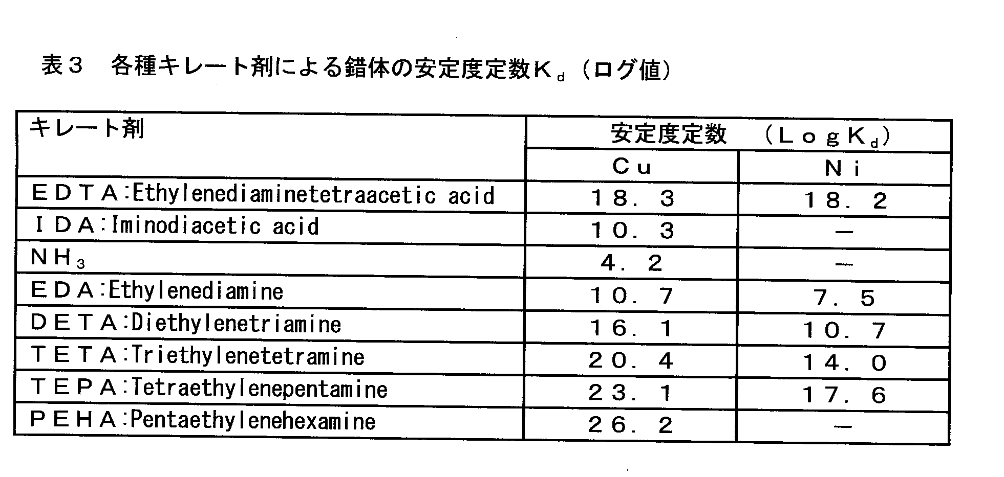
なお、一般的な電解操作において電解液の攪拌を行う場合、攪拌によって生じる電解液の流れが電解対象物に接触しないように、攪拌操作が行われる。これは、攪拌によって生じた電解液の流れが電解対象物に影響を与えないようにするという考えに基づく。本発明では、錯体を形成する薬剤がアタック金属M’またはその発生源に接触しやすいという観点から、攪拌等によって生じる電解液の流れが電解対象物に接触するように、当該薬剤を攪拌または供給してもよい。
また、バブリングのための気体としては窒素ガスやヘリウム、アルゴン等の不活性ガスが挙げられる。酸素や水素等の活性ガスは、電解液中の溶存酸素濃度に影響を与えるおそれがあり、電解対象物に影響を与えるおそれがあるため、好ましくない。 The chemical | medical agent which forms a complex, or the electrolyte solution containing this may be stirred in an electrolytic vessel. Thereby, the unreacted drug is likely to come into contact with the attack metal M ′, and the attack metal M ′ is easily captured. The stirring means is not particularly limited, and bubbling by a bubble generator, vortex flow by a magnetic stirrer, or the like may be used. Alternatively, an unreacted drug droplet may be dropped in the vicinity of the attack metal M ′. The lower limit may be 100 cc / min for bubbling, preferably 200 cc / min for bubbling, and 100 rpm, preferably 200 rpm for a stirrer, so that unreacted drug easily contacts the attack metal M ′. If the bubbling amount or the stirrer rotational speed is too high, problems such as peeling of the surface of the electrolytic object occur. Therefore, the upper limit may be 600 cc / min, preferably 500 cc / min for bubbling, and 600 rpm, preferably 500 rpm for a stirrer.
In addition, when stirring the electrolytic solution in a general electrolytic operation, the stirring operation is performed so that the flow of the electrolytic solution generated by the stirring does not contact the object to be electrolyzed. This is based on the idea that the flow of the electrolyte generated by stirring does not affect the object to be electrolyzed. In the present invention, from the viewpoint that the drug that forms the complex easily comes into contact with the attack metal M ′ or its generation source, the drug is stirred or supplied so that the flow of the electrolytic solution generated by stirring or the like comes into contact with the object to be electrolyzed. May be.
Moreover, as gas for bubbling, inert gas, such as nitrogen gas, helium, and argon, is mentioned. Active gases such as oxygen and hydrogen are not preferred because they may affect the dissolved oxygen concentration in the electrolyte and may affect the object to be electrolyzed.

電解液は、以下の2種類を用意した。
(1)4%MS:従来から知られている硫化物系介在物を残渣として回収できる4質量%サリチル酸メチル+1質量%サリチル酸+1質量%塩化テトラメチルアンモニウム(TMAC)を含有するものであり、SPEED法で用いられる電解液の一つである。
(2)4%MS+5%TETA:(1)の4%MSに、Cuイオンと錯体を形成するトリエチレンテトラミン(TETA)5体積%を添加したものである。
なお、溶媒は(1)~(2)のいずれでもメタノールとした。 In this example, a steel material containing 0.4% by mass of Cu as a steel sample was subjected to a heat treatment at 1350 ° C. × 30 min, and then rapidly cooled in water.
The following two types of electrolyte solutions were prepared.
(1) 4% MS: containing 4% by mass of methyl salicylate + 1% by mass of salicylic acid + 1% by mass of tetramethylammonium chloride (TMAC) capable of recovering conventionally known sulfide inclusions as a residue, SPEED It is one of the electrolytes used in the method.
(2) 4% MS + 5% TETA: 5% by volume of triethylenetetramine (TETA) that forms a complex with Cu ions is added to 4% MS of (1).
The solvent was methanol in any of (1) to (2).
同図において、4本の帯グラフは、それぞれ電解残渣中から検出されたMnとCuを重ねて%単位で示したものであり、左から、(1)一般的な電解液(4%MS)で、Pt電極を陰極として電解した場合、(2)一般的な電解液(4%MS)で、陰極にCuプレートを固定して電解した場合、(3)一般的な電解液に、TETA5体積%を添加した電解液(4%MS+5%TETA)とPt電極を陰極側に用いて電解した場合、(4)一般的な電解液に、TETA5体積%を添加した電解液(4%MS+5%TETA)と陰極にCuプレートを固定して電解した場合、を示す。 The results are shown in FIG.
In the figure, the four band graphs show Mn and Cu detected from the electrolytic residue in percent units, and from the left, (1) General electrolyte (4% MS) Then, when electrolysis was performed using the Pt electrode as a cathode, (2) when electrolysis was performed with a Cu plate fixed to the cathode with a general electrolyte solution (4% MS), and (3) the volume of TETA was 5 volumes. % Electrolyte solution (4% MS + 5% TETA) and a Pt electrode on the cathode side, (4) Electrolyte solution containing 5% by volume of TETA (4% MS + 5% TETA) ) And a case where electrolysis is performed with a Cu plate fixed to the cathode.
この場合、電解残渣中のCu成分は、0.0016質量%(16ppm)にまで減少している。これは、トリエチレンテトラミン(TETA)が、Cuイオンと錯体を形成し、アタック金属(Cu)が金属化合物(MnS)の表面での金属(Mn)と置換(すなわち、Artifact(擬制))されることを抑制したためと考えられる。 Further, the graph shown in (3) shows that Mn measured from the electrolytic residue obtained by electrolysis with an electrolytic solution (4% MS + 5% TETA) added with 5% by volume of triethylenetetramine while the cathode remains the Pt electrode. The concentration of Cu is shown.
In this case, the Cu component in the electrolytic residue is reduced to 0.0016% by mass (16 ppm). This is because triethylenetetramine (TETA) forms a complex with Cu ions, and the attack metal (Cu) is substituted with metal (Mn) on the surface of the metal compound (MnS) (ie, Artifact). This is considered to have been suppressed.
電解残渣から計測されるCu濃度は、0.0004質量%(4ppm)まで減少し、通常の分析であれば測定限界である5ppm以下にまで、Cu濃度を低下させることが可能であることがわかった。 Furthermore, (4) shows the measured value when the electrolyte solution containing TETA (4% MS + 5% TETA) and the fixation of the Cu plate to the Pt cathode are used in combination.
The Cu concentration measured from the electrolytic residue is reduced to 0.0004 mass% (4 ppm), and it is found that the Cu concentration can be lowered to 5 ppm or less which is the measurement limit if it is a normal analysis. It was.
5 介在物・析出相粒
6 電極(陰極側)
7 参照電極
8 電源(ポテンショスタット)
9 電解液
10 電解槽
11 電解残渣 4
7
9
Claims (15)
- 陽極と陰極を備え、陽極と陰極の間に通電することにより金属材料を電解エッチングし、金属材料中の金属化合物粒子を分離抽出する電解エッチング用装置であって、
金属化合物M’x’Ay’の溶解度積をKsp[M’x’Ay’] とし、
前記金属材料中に含まれる抽出対象金属化合物MxAyの溶解度積をKsp[MxAy] とすると、
下記式で定義されるΔが10以上となる金属M’が含まれる部材を、前記陰極の少なくとも一部に備え、
前記金属M’を含む錯体を形成する薬剤及び非水溶媒を含む電解液を収容する電解槽を備えることを特徴とする、電解エッチング用装置。
Δ=pKsp[M’x’Ay’]-pKsp[MxAy]
=(-log10Ksp[M’x’Ay’])-(-log10Ksp[MxAy])
ここで、MとM’は異なる金属元素であり、AはMまたはM’と化合物を形成する単原子または原子団であり、x、x’、y、y’はM、M’、Aの価数に応じて決まる前記化合物の組成比を表し、前記溶解度積Kspは水溶液中25℃での値である
An apparatus for electrolytic etching comprising an anode and a cathode, electrolytically etching a metal material by energizing between the anode and the cathode, and separating and extracting metal compound particles in the metal material,
The solubility product of the metal compound M ′ x ′ A y ′ is K sp [M ′ x ′ A y ′ ],
When the solubility product of the extraction target metal compound M x A y contained in the metal material is K sp [M x A y ],
A member including a metal M ′ having a Δ defined by the following formula of 10 or more is provided in at least a part of the cathode,
An apparatus for electrolytic etching, comprising: an electrolytic cell containing an electrolytic solution containing a drug that forms a complex containing the metal M ′ and a nonaqueous solvent.
Δ = pK sp [M ′ x ′ A y ′ ] −pK sp [M x A y ]
= (− Log 10 K sp [M ′ x ′ A y ′ ]) − (− log 10 K sp [M x A y ])
Here, M and M ′ are different metal elements, A is a single atom or atomic group forming a compound with M or M ′, and x, x ′, y, and y ′ are M, M ′, and A It represents the composition ratio of the compound determined according to the valence, and the solubility product Ksp is a value at 25 ° C. in an aqueous solution.
- 前記抽出対象金属化合物MxAyがMnSまたはFeSの1種または2種であることを特徴とする、請求項1に記載の電解エッチング用装置。 The apparatus for electrolytic etching according to claim 1, wherein the extraction target metal compound M x A y is one or two of MnS or FeS.
- 前記金属化合物M’x’Ay’の金属M’が、Hg、Ag、Cu、Pb、Cd、Co、Zn、およびNiの少なくとも一つであることを特徴とする、請求項1または2に記載の電解エッチング用装置。 The metal compound M ′ x ′ A y ′ in the metal compound M ′ is at least one of Hg, Ag, Cu, Pb, Cd, Co, Zn, and Ni, according to claim 1 or 2. The apparatus for electrolytic etching as described.
- 前記陰極に備えられる部材が、陰極の表面を覆うように備えられていることを特徴とする請求項1~3のいずれか1項に記載の電解エッチング用装置。 The apparatus for electrolytic etching according to any one of claims 1 to 3, wherein a member provided in the cathode is provided so as to cover a surface of the cathode.
- 前記陰極が、前記金属M’でできていることを特徴とする請求項1~3のいずれか1項に記載の電解エッチング用装置。 The apparatus for electrolytic etching according to any one of claims 1 to 3, wherein the cathode is made of the metal M '.
- 前記陰極に備えられる部材が、質量%で99.9%以上のCuおよび不可避的不純物からなることを特徴とする請求項1~5のいずれか1項に記載の電解エッチング用装置。 The apparatus for electrolytic etching according to any one of claims 1 to 5, wherein the member provided in the cathode comprises 99.9% or more of Cu and unavoidable impurities by mass%.
- 前記非水溶媒が、メタノールまたはエタノールの少なくとも一つを含んでなることを特徴とする請求項1~6のいずれか1項に記載の電解エッチング装置。 7. The electrolytic etching apparatus according to claim 1, wherein the non-aqueous solvent contains at least one of methanol or ethanol.
- 前記金属M’を含む錯体を形成する薬剤が、ポリエチレンアミン類、エチレンジアミン4酢酸、シクロヘキサンジアミン4酢酸の少なくとも一つを含んでなることを特徴とする請求項1~7のいずれか1項に記載の電解エッチング装置。 8. The agent for forming a complex containing the metal M ′ comprises at least one of polyethylene amines, ethylene diamine tetraacetic acid, and cyclohexane diamine tetraacetic acid. Electrolytic etching equipment.
- 前記薬剤がトリエチレンテトラミンを含んでなることを特徴とする、請求項8に記載の電解エッチング装置。 The electrolytic etching apparatus according to claim 8, wherein the chemical agent comprises triethylenetetramine.
- 電解液の撹拌手段をさらに備える請求項1~9のいずれか1項に記載の電解エッチング装置。 The electrolytic etching apparatus according to any one of claims 1 to 9, further comprising an electrolytic solution stirring means.
- 前記陽極表面に気泡を照射する気泡発生器を、さらに備える請求項10に記載の電解エッチング装置。 The electrolytic etching apparatus according to claim 10, further comprising a bubble generator that irradiates bubbles on the anode surface.
- 陽極と陰極を備え、陽極と陰極の間に通電することにより金属材料を電解エッチングし、金属材料中の金属化合物粒子を抽出する方法において、
金属化合物M’x’Ay’の溶解度積をKsp[M’x’Ay’] とし、
前記金属材料中に含まれる抽出対象金属化合物MxAyの溶解度積をKsp[MxAy] とすると、
下記式で定義されるΔが10以上となる金属M’が含まれる部材を、前記陰極の少なくとも一部に備え、
前記金属M’を含む錯体を形成する薬剤及び非水溶媒を含む電解液を用いることを特徴とする、金属化合物粒子の抽出方法。
Δ=pKsp[M’x’Ay’]-pKsp[MxAy]
=(-log10Ksp[M’x’Ay’])-(-log10Ksp[MxAy])
ここで、MとM’は異なる金属元素であり、AはMまたはM’と化合物を形成する単原子または原子団であり、x、x’、y、y’はM、M’、Aの価数に応じて決まる前記化合物の組成比を表し、前記溶解度積Kspは水溶液中25℃での値である
In a method of providing an anode and a cathode, electrolytically etching a metal material by energizing between the anode and the cathode, and extracting metal compound particles in the metal material,
The solubility product of the metal compound M ′ x ′ A y ′ is K sp [M ′ x ′ A y ′ ],
When the solubility product of the extraction target metal compound M x A y contained in the metal material is K sp [M x A y ],
A member including a metal M ′ having a Δ defined by the following formula of 10 or more is provided in at least a part of the cathode,
A method for extracting metal compound particles, wherein an electrolyte containing a drug that forms a complex containing the metal M ′ and a non-aqueous solvent is used.
Δ = pK sp [M ′ x ′ A y ′ ] −pK sp [M x A y ]
= (− Log 10 K sp [M ′ x ′ A y ′ ]) − (− log 10 K sp [M x A y ])
Here, M and M ′ are different metal elements, A is a single atom or atomic group forming a compound with M or M ′, and x, x ′, y, and y ′ are M, M ′, and A It represents the composition ratio of the compound determined according to the valence, and the solubility product Ksp is a value at 25 ° C. in an aqueous solution.
- 前記電解エッチングを行う際に、電解液を撹拌しながら電解エッチングすることを特徴とする請求項12に記載の金属化合物粒子の抽出方法。 13. The method for extracting metal compound particles according to claim 12, wherein the electrolytic etching is performed while stirring the electrolytic solution when performing the electrolytic etching.
- 電解液をマグネチックスターラーで撹拌することを特徴とする請求項13に記載の金属化合物粒子の抽出方法。 The method for extracting metal compound particles according to claim 13, wherein the electrolytic solution is stirred with a magnetic stirrer.
- 電解液中に気泡をバブリングすることを特徴とする請求項13に記載の金属化合物粒子の抽出方法。 14. The method for extracting metal compound particles according to claim 13, wherein bubbles are bubbled in the electrolytic solution.
Priority Applications (9)
| Application Number | Priority Date | Filing Date | Title |
|---|---|---|---|
| PCT/JP2017/005995 WO2017142084A1 (en) | 2016-02-18 | 2017-02-17 | Device for electrolytic etching and method for extracting metal compound particles |
| US15/999,791 US11111595B2 (en) | 2016-02-18 | 2017-02-17 | Apparatus for electrolytic etching and dissolution and method for extracting metal compound particles |
| RU2018132868A RU2698004C1 (en) | 2016-02-18 | 2017-02-17 | Device for electrolytic etching and dissolution and a method for extracting particles of a metallic compound |
| EP17753338.7A EP3418711B1 (en) | 2016-02-18 | 2017-02-17 | Apparatus for electrolytic etching and dissolution and method for extracting metal compound particles |
| JP2018500235A JP6610767B2 (en) | 2016-02-18 | 2017-02-17 | Electrolytic etching apparatus and method for extracting metal compound particles |
| BR112018016748-7A BR112018016748B1 (en) | 2016-02-18 | 2017-02-17 | APPARATUS FOR CAUSTICING AND ELECTROLYTIC DISSOLUTION AND METHOD FOR EXTRACTING PARTICLES FROM METALLIC COMPOUNDS |
| PL17753338T PL3418711T3 (en) | 2016-02-18 | 2017-02-17 | Apparatus for electrolytic etching and dissolution and method for extracting metal compound particles |
| CN201780010612.0A CN108603820B (en) | 2016-02-18 | 2017-02-17 | Apparatus for electrolytic etching and method for extracting metal compound particles |
| KR1020187023123A KR102214098B1 (en) | 2016-02-18 | 2017-02-17 | Electrolytic etching apparatus and method for extracting metal compound particles |
Applications Claiming Priority (3)
| Application Number | Priority Date | Filing Date | Title |
|---|---|---|---|
| JP2016-028895 | 2016-02-18 | ||
| JP2016028895 | 2016-02-18 | ||
| PCT/JP2017/005995 WO2017142084A1 (en) | 2016-02-18 | 2017-02-17 | Device for electrolytic etching and method for extracting metal compound particles |
Publications (1)
| Publication Number | Publication Date |
|---|---|
| WO2017142084A1 true WO2017142084A1 (en) | 2017-08-24 |
Family
ID=59625996
Family Applications (1)
| Application Number | Title | Priority Date | Filing Date |
|---|---|---|---|
| PCT/JP2017/005995 WO2017142084A1 (en) | 2016-02-18 | 2017-02-17 | Device for electrolytic etching and method for extracting metal compound particles |
Country Status (10)
| Country | Link |
|---|---|
| US (1) | US11111595B2 (en) |
| EP (1) | EP3418711B1 (en) |
| JP (1) | JP6610767B2 (en) |
| KR (1) | KR102214098B1 (en) |
| CN (1) | CN108603820B (en) |
| BR (1) | BR112018016748B1 (en) |
| PL (1) | PL3418711T3 (en) |
| RU (1) | RU2698004C1 (en) |
| TW (1) | TWI642935B (en) |
| WO (1) | WO2017142084A1 (en) |
Cited By (2)
| Publication number | Priority date | Publication date | Assignee | Title |
|---|---|---|---|---|
| WO2021106705A1 (en) * | 2019-11-25 | 2021-06-03 | Jfeスチール株式会社 | Method for extracting precipitate and/or inclusion, method for quantitative analysis of precipitate and/or inclusion, electrolyte, and method for producing replica sample |
| WO2021106711A1 (en) * | 2019-11-25 | 2021-06-03 | Jfeスチール株式会社 | Method for extracting precipitates and/or inclusions, method for quantitatively analyzing precipitates and/or inclusions, and electrolyte |
Families Citing this family (4)
| Publication number | Priority date | Publication date | Assignee | Title |
|---|---|---|---|---|
| WO2017142088A1 (en) * | 2016-02-18 | 2017-08-24 | 新日鐵住金株式会社 | Method for extracting metal compound particles, method for analyzing metal compound particles, and electrolyte solution used in said methods |
| CN111238915B (en) * | 2020-02-12 | 2021-05-07 | 北京科技大学 | Method for extracting non-metallic inclusions in high-temperature alloy |
| CN111596094B (en) * | 2020-05-12 | 2023-04-18 | 上海大学 | Three-dimensional etching device and method for nonmetallic inclusions in steel |
| KR200496071Y1 (en) * | 2020-06-17 | 2022-10-26 | 두산에너빌리티 (주) | Multi-terminal jig for electrolytic etching test |
Citations (2)
| Publication number | Priority date | Publication date | Assignee | Title |
|---|---|---|---|---|
| JPH07260772A (en) * | 1994-03-25 | 1995-10-13 | Nippon Steel Corp | Method for quickly displaying segregation state of steel having high resolution and solidified texture and transfer method |
| JP2007127454A (en) * | 2005-11-01 | 2007-05-24 | Shikoku Electric Power Co Inc | Extraction method of precipitate from metallic material, and discrimination method for deterioration degree of metallic material using the extraction method |
Family Cites Families (18)
| Publication number | Priority date | Publication date | Assignee | Title |
|---|---|---|---|---|
| JPS5479131A (en) * | 1977-12-07 | 1979-06-23 | Okuno Chem Ind Co | Electrolytic bath for removing electrodeposited metal on stainless steel substrate |
| JPS59141035A (en) * | 1983-02-01 | 1984-08-13 | Daido Steel Co Ltd | Collection of nonmetal inclusion in metal |
| SU1257446A1 (en) | 1984-07-18 | 1986-09-15 | Предприятие П/Я В-2120 | Electrolyte for detecting boundaries of austenite grains in stainless steel |
| JPS62238379A (en) | 1986-04-07 | 1987-10-19 | Asahi Kagaku Kogyo Kk | Additive for chemical dissolving solution for metallic surface |
| JPH04143290A (en) | 1990-10-05 | 1992-05-18 | Nippon Sanso Kk | Surface treatment |
| SU1755103A1 (en) | 1991-01-08 | 1992-08-15 | Научно-исследовательский институт прикладных физических проблем им.А.Н.Севченко | Method of making a silicon specimen with angle lap |
| JP3454171B2 (en) | 1998-10-30 | 2003-10-06 | Jfeスチール株式会社 | Non-aqueous solvent electrolyte for extracting inclusions or precipitates in steel samples and method for electrolytic extraction of steel samples |
| US7323416B2 (en) * | 2001-03-14 | 2008-01-29 | Applied Materials, Inc. | Method and composition for polishing a substrate |
| JP3984431B2 (en) | 2001-04-04 | 2007-10-03 | 新日本製鐵株式会社 | Electrolyte composition for steel materials and method for analyzing inclusions or precipitates thereby |
| JP4280004B2 (en) | 2001-06-01 | 2009-06-17 | 新日本製鐵株式会社 | Semi-processed non-oriented electrical steel sheet with extremely excellent iron loss and magnetic flux density and method for producing the same |
| JP2004317203A (en) | 2003-04-14 | 2004-11-11 | Nippon Steel Corp | Method of evaluating inclusion and precipitate in metal and evaluation tool therefor |
| JP2006274293A (en) | 2005-03-28 | 2006-10-12 | Nikko Kinzoku Kk | Method for producing sheet-form electrolytic copper |
| JP5098843B2 (en) * | 2007-06-29 | 2012-12-12 | Jfeスチール株式会社 | Method for determining the solid solution content of the element of interest in a metal sample |
| KR100916479B1 (en) | 2007-11-30 | 2009-09-08 | 삼성전기주식회사 | Electrolyte for electro-chemical machining of metal product |
| WO2009131175A1 (en) * | 2008-04-25 | 2009-10-29 | 新日本製鐵株式会社 | Method of determining particle size distribution of fine particles contained in metallic material |
| JP5583704B2 (en) | 2011-10-28 | 2014-09-03 | 富士フイルム株式会社 | Lithographic printing plate support manufacturing method and planographic printing plate support manufacturing apparatus |
| JP5958501B2 (en) | 2013-08-07 | 2016-08-02 | Jfeスチール株式会社 | Method for evaluating grain-oriented electrical steel sheet and method for producing grain-oriented electrical steel sheet |
| CN111976804B (en) | 2014-12-24 | 2023-06-23 | 威尔泰克联合股份有限公司 | Cart with detachable wheel seat |
-
2017
- 2017-02-17 PL PL17753338T patent/PL3418711T3/en unknown
- 2017-02-17 CN CN201780010612.0A patent/CN108603820B/en active Active
- 2017-02-17 BR BR112018016748-7A patent/BR112018016748B1/en active IP Right Grant
- 2017-02-17 JP JP2018500235A patent/JP6610767B2/en active Active
- 2017-02-17 TW TW106105333A patent/TWI642935B/en active
- 2017-02-17 US US15/999,791 patent/US11111595B2/en active Active
- 2017-02-17 RU RU2018132868A patent/RU2698004C1/en active
- 2017-02-17 KR KR1020187023123A patent/KR102214098B1/en active IP Right Grant
- 2017-02-17 EP EP17753338.7A patent/EP3418711B1/en active Active
- 2017-02-17 WO PCT/JP2017/005995 patent/WO2017142084A1/en active Application Filing
Patent Citations (2)
| Publication number | Priority date | Publication date | Assignee | Title |
|---|---|---|---|---|
| JPH07260772A (en) * | 1994-03-25 | 1995-10-13 | Nippon Steel Corp | Method for quickly displaying segregation state of steel having high resolution and solidified texture and transfer method |
| JP2007127454A (en) * | 2005-11-01 | 2007-05-24 | Shikoku Electric Power Co Inc | Extraction method of precipitate from metallic material, and discrimination method for deterioration degree of metallic material using the extraction method |
Non-Patent Citations (1)
| Title |
|---|
| See also references of EP3418711A4 * |
Cited By (5)
| Publication number | Priority date | Publication date | Assignee | Title |
|---|---|---|---|---|
| WO2021106705A1 (en) * | 2019-11-25 | 2021-06-03 | Jfeスチール株式会社 | Method for extracting precipitate and/or inclusion, method for quantitative analysis of precipitate and/or inclusion, electrolyte, and method for producing replica sample |
| WO2021106711A1 (en) * | 2019-11-25 | 2021-06-03 | Jfeスチール株式会社 | Method for extracting precipitates and/or inclusions, method for quantitatively analyzing precipitates and/or inclusions, and electrolyte |
| JP6919775B1 (en) * | 2019-11-25 | 2021-08-18 | Jfeスチール株式会社 | Method for extracting precipitates and / or inclusions, method for quantitative analysis of precipitates and / or inclusions, method for preparing electrolytic solution, and replica sample. |
| JPWO2021106711A1 (en) * | 2019-11-25 | 2021-12-02 | Jfeスチール株式会社 | A method for extracting precipitates and / or inclusions, a method for quantitative analysis of precipitates and / or inclusions, and an electrolytic solution. |
| JP7010411B2 (en) | 2019-11-25 | 2022-01-26 | Jfeスチール株式会社 | A method for extracting precipitates and / or inclusions, a method for quantitative analysis of precipitates and / or inclusions, and an electrolytic solution. |
Also Published As
| Publication number | Publication date |
|---|---|
| CN108603820B (en) | 2021-07-27 |
| BR112018016748B1 (en) | 2022-12-20 |
| JPWO2017142084A1 (en) | 2018-12-27 |
| US20200141843A1 (en) | 2020-05-07 |
| TWI642935B (en) | 2018-12-01 |
| TW201740106A (en) | 2017-11-16 |
| EP3418711B1 (en) | 2021-05-19 |
| EP3418711A4 (en) | 2019-10-09 |
| RU2698004C1 (en) | 2019-08-21 |
| US11111595B2 (en) | 2021-09-07 |
| EP3418711A1 (en) | 2018-12-26 |
| CN108603820A (en) | 2018-09-28 |
| KR102214098B1 (en) | 2021-02-09 |
| JP6610767B2 (en) | 2019-11-27 |
| PL3418711T3 (en) | 2021-11-08 |
| BR112018016748A2 (en) | 2018-12-26 |
| KR20180102139A (en) | 2018-09-14 |
Similar Documents
| Publication | Publication Date | Title |
|---|---|---|
| JP6610767B2 (en) | Electrolytic etching apparatus and method for extracting metal compound particles | |
| JP6690699B2 (en) | Method for extracting metal compound particles, method for analyzing metal compound particles, and electrolytic solution used therein | |
| TWI426157B (en) | The stripping gold components and the method of stripping gold | |
| JP6897532B2 (en) | Electrolytic solution for extracting metal compound particles, and electrolytic extraction method using it | |
| Popescu et al. | Recovery of silver and gold from electronic waste by electrodeposition in ethaline ionic liquid | |
| JP2019039710A (en) | Extraction method of carbide and/or nitride in metal material, analysis method of the carbide and/or nitride, analysis method of quantity of solid solution carbon and/or quantity of solid solution nitrogen in the metal material, and electrolytic solution used therefor | |
| JP2015017318A (en) | Method for copper electroextraction from oil-containing electrolytic solution | |
| JP4103661B2 (en) | Electrolytic solution for extraction analysis of precipitates and / or inclusions in steel, and method for electrolytic extraction of precipitates and / or inclusions in steel using the same | |
| JP5324141B2 (en) | Method for analyzing inclusions containing CaO in steel | |
| JP2019039029A (en) | Cu-CONTAINING STEEL SHEET | |
| JP2015209584A (en) | Gold separation liquid and method and apparatus for gold recovery using the same | |
| JP4996023B2 (en) | Prevention of lead elution from lead-containing copper alloy materials | |
| JP2014111802A (en) | Method for recovering rare earth metals | |
| Łoś et al. | A Selective Separation of Platinum Group Metals from the Fe-PGM Alloy Using Electrodeposition Combined with Electrochemical Dealloying | |
| RU2522905C1 (en) | Method of rare-earth elements extraction from liquid alloys with zinc | |
| Van der Spoel Badenhorst | Development of an iron electrowinning process using anion exchange membranes | |
| JP2010270357A (en) | Method for recycling scrap of copper or copper alloy plated with nickel | |
| JP2004004009A (en) | Extraction separation method of crystal/sludge in copper alloy and liquid for extraction separation used therefor |
Legal Events
| Date | Code | Title | Description |
|---|---|---|---|
| 121 | Ep: the epo has been informed by wipo that ep was designated in this application |
Ref document number: 17753338 Country of ref document: EP Kind code of ref document: A1 |
|
| ENP | Entry into the national phase |
Ref document number: 20187023123 Country of ref document: KR Kind code of ref document: A |
|
| WWE | Wipo information: entry into national phase |
Ref document number: 1020187023123 Country of ref document: KR |
|
| WWE | Wipo information: entry into national phase |
Ref document number: 2018500235 Country of ref document: JP |
|
| NENP | Non-entry into the national phase |
Ref country code: DE |
|
| REG | Reference to national code |
Ref country code: BR Ref legal event code: B01A Ref document number: 112018016748 Country of ref document: BR |
|
| WWE | Wipo information: entry into national phase |
Ref document number: 2017753338 Country of ref document: EP |
|
| ENP | Entry into the national phase |
Ref document number: 2017753338 Country of ref document: EP Effective date: 20180918 |
|
| ENP | Entry into the national phase |
Ref document number: 112018016748 Country of ref document: BR Kind code of ref document: A2 Effective date: 20180816 |