WO2017141924A1 - 医療デバイス - Google Patents
医療デバイス Download PDFInfo
- Publication number
- WO2017141924A1 WO2017141924A1 PCT/JP2017/005379 JP2017005379W WO2017141924A1 WO 2017141924 A1 WO2017141924 A1 WO 2017141924A1 JP 2017005379 W JP2017005379 W JP 2017005379W WO 2017141924 A1 WO2017141924 A1 WO 2017141924A1
- Authority
- WO
- WIPO (PCT)
- Prior art keywords
- rotating body
- guide
- medical device
- cutting
- distal end
- Prior art date
Links
Images


Classifications
-
- A—HUMAN NECESSITIES
- A61—MEDICAL OR VETERINARY SCIENCE; HYGIENE
- A61B—DIAGNOSIS; SURGERY; IDENTIFICATION
- A61B17/00—Surgical instruments, devices or methods, e.g. tourniquets
- A61B17/32—Surgical cutting instruments
- A61B17/3205—Excision instruments
- A61B17/3207—Atherectomy devices working by cutting or abrading; Similar devices specially adapted for non-vascular obstructions
- A61B17/320758—Atherectomy devices working by cutting or abrading; Similar devices specially adapted for non-vascular obstructions with a rotating cutting instrument, e.g. motor driven
-
- A—HUMAN NECESSITIES
- A61—MEDICAL OR VETERINARY SCIENCE; HYGIENE
- A61B—DIAGNOSIS; SURGERY; IDENTIFICATION
- A61B17/00—Surgical instruments, devices or methods, e.g. tourniquets
- A61B17/22—Implements for squeezing-off ulcers or the like on the inside of inner organs of the body; Implements for scraping-out cavities of body organs, e.g. bones; Calculus removers; Calculus smashing apparatus; Apparatus for removing obstructions in blood vessels, not otherwise provided for
-
- A—HUMAN NECESSITIES
- A61—MEDICAL OR VETERINARY SCIENCE; HYGIENE
- A61B—DIAGNOSIS; SURGERY; IDENTIFICATION
- A61B17/00—Surgical instruments, devices or methods, e.g. tourniquets
- A61B17/32—Surgical cutting instruments
- A61B17/3205—Excision instruments
- A61B17/3207—Atherectomy devices working by cutting or abrading; Similar devices specially adapted for non-vascular obstructions
- A61B17/320783—Atherectomy devices working by cutting or abrading; Similar devices specially adapted for non-vascular obstructions through side-hole, e.g. sliding or rotating cutter inside catheter
-
- A—HUMAN NECESSITIES
- A61—MEDICAL OR VETERINARY SCIENCE; HYGIENE
- A61B—DIAGNOSIS; SURGERY; IDENTIFICATION
- A61B90/00—Instruments, implements or accessories specially adapted for surgery or diagnosis and not covered by any of the groups A61B1/00 - A61B50/00, e.g. for luxation treatment or for protecting wound edges
- A61B90/08—Accessories or related features not otherwise provided for
-
- A—HUMAN NECESSITIES
- A61—MEDICAL OR VETERINARY SCIENCE; HYGIENE
- A61B—DIAGNOSIS; SURGERY; IDENTIFICATION
- A61B17/00—Surgical instruments, devices or methods, e.g. tourniquets
- A61B17/22—Implements for squeezing-off ulcers or the like on the inside of inner organs of the body; Implements for scraping-out cavities of body organs, e.g. bones; Calculus removers; Calculus smashing apparatus; Apparatus for removing obstructions in blood vessels, not otherwise provided for
- A61B2017/22038—Implements for squeezing-off ulcers or the like on the inside of inner organs of the body; Implements for scraping-out cavities of body organs, e.g. bones; Calculus removers; Calculus smashing apparatus; Apparatus for removing obstructions in blood vessels, not otherwise provided for with a guide wire
- A61B2017/22039—Implements for squeezing-off ulcers or the like on the inside of inner organs of the body; Implements for scraping-out cavities of body organs, e.g. bones; Calculus removers; Calculus smashing apparatus; Apparatus for removing obstructions in blood vessels, not otherwise provided for with a guide wire eccentric
-
- A—HUMAN NECESSITIES
- A61—MEDICAL OR VETERINARY SCIENCE; HYGIENE
- A61B—DIAGNOSIS; SURGERY; IDENTIFICATION
- A61B17/00—Surgical instruments, devices or methods, e.g. tourniquets
- A61B17/22—Implements for squeezing-off ulcers or the like on the inside of inner organs of the body; Implements for scraping-out cavities of body organs, e.g. bones; Calculus removers; Calculus smashing apparatus; Apparatus for removing obstructions in blood vessels, not otherwise provided for
- A61B2017/22079—Implements for squeezing-off ulcers or the like on the inside of inner organs of the body; Implements for scraping-out cavities of body organs, e.g. bones; Calculus removers; Calculus smashing apparatus; Apparatus for removing obstructions in blood vessels, not otherwise provided for with suction of debris
-
- A—HUMAN NECESSITIES
- A61—MEDICAL OR VETERINARY SCIENCE; HYGIENE
- A61B—DIAGNOSIS; SURGERY; IDENTIFICATION
- A61B17/00—Surgical instruments, devices or methods, e.g. tourniquets
- A61B17/32—Surgical cutting instruments
- A61B2017/320052—Guides for cutting instruments
-
- A—HUMAN NECESSITIES
- A61—MEDICAL OR VETERINARY SCIENCE; HYGIENE
- A61B—DIAGNOSIS; SURGERY; IDENTIFICATION
- A61B17/00—Surgical instruments, devices or methods, e.g. tourniquets
- A61B17/32—Surgical cutting instruments
- A61B2017/320064—Surgical cutting instruments with tissue or sample retaining means
-
- A—HUMAN NECESSITIES
- A61—MEDICAL OR VETERINARY SCIENCE; HYGIENE
- A61B—DIAGNOSIS; SURGERY; IDENTIFICATION
- A61B17/00—Surgical instruments, devices or methods, e.g. tourniquets
- A61B17/32—Surgical cutting instruments
- A61B17/3205—Excision instruments
- A61B17/3207—Atherectomy devices working by cutting or abrading; Similar devices specially adapted for non-vascular obstructions
- A61B17/320783—Atherectomy devices working by cutting or abrading; Similar devices specially adapted for non-vascular obstructions through side-hole, e.g. sliding or rotating cutter inside catheter
- A61B2017/320791—Atherectomy devices working by cutting or abrading; Similar devices specially adapted for non-vascular obstructions through side-hole, e.g. sliding or rotating cutter inside catheter with cutter extending outside the cutting window
-
- A—HUMAN NECESSITIES
- A61—MEDICAL OR VETERINARY SCIENCE; HYGIENE
- A61B—DIAGNOSIS; SURGERY; IDENTIFICATION
- A61B90/00—Instruments, implements or accessories specially adapted for surgery or diagnosis and not covered by any of the groups A61B1/00 - A61B50/00, e.g. for luxation treatment or for protecting wound edges
- A61B90/08—Accessories or related features not otherwise provided for
- A61B2090/0801—Prevention of accidental cutting or pricking
- A61B2090/08021—Prevention of accidental cutting or pricking of the patient or his organs
Definitions
- the present invention relates to a medical device for cutting an object existing in a living body lumen.
- a treatment using a balloon catheter or a stent placement has been conventionally performed.
- treatment using a balloon catheter or stent is sufficient. In some cases, the effect cannot be obtained.
- Patent Document 1 has a structure in which a rotating body with a cutting portion (blade surface) that applies a cutting force to a narrowed portion is provided at the distal end of a long catheter. Proposed.
- the rotated cutting part is brought into contact with the stenosis part and the stenosis part is scraped off.
- the cutting part may penetrate the blood vessel wall.
- the cutting part is made smaller (smaller diameter) together with the rotating body, the risk of the cutting part penetrating through the blood vessel wall can be reduced, but the cutting efficiency decreases as the cutting part becomes smaller. Will be invited.
- the present invention has been made in view of the above-described problems, and an object of the present invention is to provide a medical device with further improved safety when cutting an object to be cut.
- a medical device is a medical device for cutting an object in a living body lumen, and has a rotatable long member, a cutting portion for cutting the object, and a tip of the long member.
- a rotating body that is disposed on the side and rotates in accordance with the rotation of the elongate member, a guide portion that is disposed on the distal end side of the rotating body with a space between the rotating body, and the guide portion
- a front end member provided with a support portion that defines the dimension of the space in the axial direction of the long member, and the guide portion is viewed from the front end side of the front end member, It arrange
- the guide portion disposed on the distal end side of the rotating body can be cut by the cutting portion (the range where the cutting portion and the object are in contact). Limit. For this reason, even when the rotating body reaches the wall portion of the living body lumen during the treatment, the rotating body can be suitably prevented from penetrating the wall portion.
- FIG. 2A It is a figure which shows the medical device which concerns on embodiment. It is a side view which expands and shows the front-end
- FIG. 2A It is sectional drawing which follows the 4D-4D line
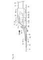
- FIG. 1 to 4 are diagrams for explaining the configuration of each part of the medical device 1 according to the embodiment, and FIG. 5 is a diagram for explaining the operation of the medical device 1.
- FIG. 1 is a diagram showing the overall configuration
- FIGS. 2A and 2B are enlarged views of the distal end member 30 provided in the medical device 1
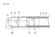
- FIG. 3A is a long member 10 and a rotating body provided in the medical device 1.
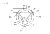
- FIG. 3B is a diagram showing the positional relationship between the cutting portion 22 of the rotating body 20 and the tip member 30, and
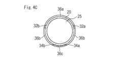
- FIGS. 4A to 4C are cross-sectional views of the respective portions of the medical device 1.
- the medical device 1 is configured as a medical instrument that can be used for a treatment of cutting an object such as a stenosis part S or an obstruction part formed in a living body lumen.
- a medical instrument that can be used for a treatment of cutting an object such as a stenosis part S or an obstruction part formed in a living body lumen.
- an example in which the medical device 1 is applied to a treatment for cutting the stenosis S formed in a blood vessel H that is a living body lumen will be described.
- distal side distal side
- proximal end side proximal side
- the medical device 1 includes a rotatable long member 10 inserted into a blood vessel H, a rotating body 20 having a cutting portion 22 for cutting the stenosis S, and the long member 10.
- a distal end member 30 disposed on the distal end side of the elongate member 10 and a hand operating section 150 disposed on the proximal end side of the long member 10.
- the rotating body 20 is arranged on the distal end side of the long member 10 covered with the cover material 13. As shown in FIG. 3A, the rotating body 20 has a hollow shape including a lumen 25 extending in the axial direction. Moreover, as shown to FIG. 3B, the rotary body 20 has a substantially circular shape in front view.
- the cutting part 22 included in the rotating body 20 is configured by a trepan blade surface (an annular blade surface whose thickness decreases toward the tip side) known in the medical field. Since the rotator 20 has the cutting part 22 configured with such a blade surface, the rotator 20 can smoothly enter the stenosis S, and the stenosis S is a soft tissue or the like. Even in this case, the narrowed portion S can be cut efficiently.
- a trepan blade surface an annular blade surface whose thickness decreases toward the tip side
- the rotating body 20 can be made of, for example, a known metal material, resin material, ceramics or the like having biocompatibility.
- the metal material include stainless steel, nickel titanium (titanium alloy), tungsten, cobalt chrome, titanium, and tungsten carbide. What improved the hardness of the surface can be used.
- the cutting unit 22 may have a multilayer structure in which, for example, the same type or different types of metals are arranged in multiple layers.
- the resin material examples include BS (acrylonitrile, butadiene, styrene copolymer synthetic resin), polyethylene, polypropylene, nylon, PEEK, polycarbonate, acrylic, polyacetal, modified polyphenylene ether, acrylonitrile styrene, and glass fiber in these resin materials. What added the additive and improved the intensity
- the shape, structure, etc. of the cutting part 22 are not particularly limited as long as the constricted part S to be cut can be cut.
- the cutting part 22 can also be constituted by a blade surface having a shape (sawtooth shape) cut out in an uneven shape on the tip side.
- the narrowed part S can be finely crushed, so that the cutting efficiency can be increased.
- the distal end portion of the long member 10 is inserted into the lumen 25 of the rotating body 20.
- the distal end portion of the long member 10 is fixed to the proximal end portion of the rotating body 20.
- the long member 10 is constituted by a long coil spring having a lumen 15 extending in the axial direction.
- the coil spring for example, a known metal or resin can be used.
- the long member 10 and the rotating body 20 can be fixed by a method such as adhesion, fusion, or welding with an adhesive in consideration of the material.
- the long member 10 is not particularly limited in structure, material, or the like as long as it can transmit a rotational driving force from the proximal end side to the distal end side (from the hand operation unit 150 side to the rotating body 20 side).
- the long member 10 is made of a resin tube formed of a single layer or a plurality of layers, a resin tube added with a reinforcing member such as a blade, or a metal made of slit processing or spiral processing. It is also possible to configure a pipe, a core material (core metal), and a metal shaft provided with a reinforcing body fixed to the core material.
- the long member 10 is covered with a predetermined cover material 13.
- the cover material 13 protects the living tissue from the long member 10 in the living body. Further, the cover member 13 prevents debris D (see FIG. 5A) and the like generated along with the cutting of the narrowed portion S from flowing out from the lumen 15 of the long member 10.
- a hollow tube made of a known resin material such as polyethylene, polypropylene, or polyamide can be used.
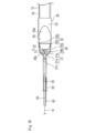
- the hand operation unit 150 includes a hub 151, a connector unit 153 provided in the hub 151, and a port 155 provided in the connector unit 153.
- the elongate member 10 has a proximal end side inserted through a hub 151 and led out from a proximal end port 152.
- a valve body 157 for preventing fluid and the like from leaking from the proximal end port 152 is disposed at the proximal end portion of the hub 151.
- the base end side of the cover member 13 covering the long member 10 is inserted into the hub 151 and fixed at a predetermined position in the hub 151. The cover member 13 is not fixed (connected) to the long member 10 and the rotating body 20.
- the connector part 153 can be configured by, for example, a Y connector known in the medical field.
- the port 155 provided in the connector part 153 is provided with a three-way cock for operating the flow of fluid inside and outside the port 155.
- the port 155 can be connected to the suction device 190 via, for example, a tube 191 through which fluid can flow.
- the suction device 190 can be configured by, for example, a known fluid suction pump that can generate a negative pressure.
- the base end portion of the long member 10 is configured to be connectable to the external drive device 180 via a predetermined connector (not shown).
- the external drive device 180 is provided with a drive source configured by a known electric motor or the like that generates a drive force for rotating the long member 10.
- the long member 10 rotates as indicated by an arrow r1 in FIG. 3A.
- the rotating body 20 disposed at the tip of the long member 10 rotates as indicated by an arrow r2 in FIG. 3A.
- the cover member 13 is not fixed to the long member 10 and the rotating body 20, the cover member 13 does not rotate even when the long member 10 rotates.
- the operation control of the external drive device 180 and the suction device 190 can be performed by a control unit (not shown), for example.
- a control unit As a control part, what was comprised by the well-known microcomputer provided with CPU, RAM, ROM etc. can be used, for example.
- the control unit may be mounted on the external drive device 180 or the suction device 190, for example, or may be incorporated in a device other than the external drive device 180 or the suction device 190 and connected to each of the devices 180 and 190.
- a control signal or the like may be transmitted and received between the two by wire or wirelessly.
- Rotation direction of the rotating body 20 when performing the treatment may be either clockwise or counterclockwise. Further, the clockwise rotation and the counterclockwise rotation may be appropriately switched and rotated.
- the tip member 30 supports the guide portion 31 and the guide portion 31 disposed on the tip side of the rotating body 20 with a space g between the tip member 30 and the rotating member 20.
- a support portion 32 that defines the dimension of the space g in the axial direction of the long member 10, a base portion 33 provided on the base end side of the support portion 32, a bottom portion 34 disposed on the bottom surface side of the rotating body 20, and a bottom portion 34 and a connecting portion 35 extending to the tip side.
- the base portion 33 is a portion provided on the proximal end side of the distal end member 30 and is fixed to the cover material 13 as will be described later.
- the support portion 32 extends from the base portion 33 toward the distal end side, and is disposed along the side surface of the rotating body 20.
- the bottom portion 34 extends from the base portion 33 toward the distal end side, and is disposed along the bottom surface of the rotating body 20.
- the guide portion 31 extends from the support portion 32 toward the distal end side, and the distal end portion is connected to the coupling portion 35.
- the base 33 has a hollow shape. As shown in FIG. 3A, the base end portion of the rotating body 20, the tip end portion of the long member 10, and the tip end portion of the cover member 13 are inserted into the base portion 33. In FIG. 3A, the tip member 30 is indicated by a broken line in order to clearly show the configuration in the tip member 30.
- the base 33 of the tip member 30 is fixed to the outer peripheral surface of the tip of the cover member 13.
- the fixing may be performed by a mechanical method such as fitting or screwing, or by a method such as adhesion, fusion, or welding with an adhesive in consideration of the material of the tip member 30 and the base 33. May be.
- the tip member 30 is fixed to the cover member 13, but is not fixed to the long member 10 and the rotating body 20. Further, as described above, the cover member 13 is not fixed to the long member 10 and the rotating body 20. Therefore, like the cover member 13, the tip member 30 does not rotate even when the long member 10 rotates.
- the guide part 31 has a first guide part 31a and a second guide part 31b.
- the interval between the first guide part 31a and the second guide part 31b gradually decreases toward the tip side. Further, as shown in FIG. 2A, the guide portions 31 a and 31 b have a curved shape so that the height gradually decreases toward the connecting portion 35. Each guide part 31a, 31b is integrally connected on the tip side from the rotating body 20.
- the support part 32 includes a first support part 32a and a second support part 32b.
- the first support portion 32a extends between the base portion 33 and the first guide portion 31a.
- the second support portion 32b extends between the base portion 33 and the second guide portion 31b.
- the base 33 is fixed to the cover material 13. Accordingly, the first guide portion 31a is supported (connected) to the cover member 13 via the first support portion 32a and the base portion 33, and the second guide portion 31b is supported by the second support portion 32b and the base portion 33. It is supported (connected) to the cover material 13 via
- the first support portion 32a supports the first guide portion 31a with respect to the cover material 13 as described above, thereby forming a space g between the first guide portion 31a and the rotating body 20.
- the second support portion 32 b supports the second guide portion 31 b with respect to the cover material 13, thereby forming a space g between the first guide portion 31 a and the rotating body 20.
- the space g is disposed between the base end portions of the guide portions 31a and 31b (positions indicated by broken lines b in FIGS. 2A and 2B) and the distal end 21 of the rotating body 20.
- the size of the space g (the length in the axial direction, the height in the direction crossing the axial direction), the shape of the space g, and the like are such that the cut stenosis (for example, debris D) is a rotating body through the space g.
- the cut stenosis for example, debris D
- the outer peripheral length of the first support portion 32a and the outer peripheral length of the second support portion 32b are smaller than the outer peripheral length of the rotating body 20 (the outer diameter of the cutting portion 22 and the proximal end portion of the cutting portion 22).
- the bottom 34 has a first bottom 34a and a second bottom 34b.
- the interval between the first bottom portion 34a and the second bottom portion 34b gradually decreases toward the tip side.
- the bottom portions 34 a and 34 b are integrally connected on the tip side with respect to the rotating body 20, and are connected to a connecting portion 35 disposed on the tip side of the rotating body 20.
- the rotating body 20 includes three support portions 32a and 32b disposed on the side surface side of the rotating body 20 and bottom portions 34a and 34b disposed on the bottom surface side of the rotating body 20 so that the rotating body 20 has three side surfaces and a bottom surface side. It is held in a state of being sandwiched from the direction. For this reason, when the rotating body 20 rotates, the rotating shaft is stabilized, so that the rotating body 20 can be smoothly rotated. Further, even if the rotary body 20 and the long member 10 are unintentionally detached, the rotary body 20 can be held by the support portions 32a and 32b and the bottom portions 34a and 34b. Can be prevented from falling off.
- each support part 32a, 32b prevents the rotating body 20 from inadvertently projecting on the distal end side of the rotating body 20, and prevents the rotating body 20 from excessively entering the narrowed portion S. For this reason, it becomes possible to suitably prevent the normal tissue from being damaged by the rotating body 20 during the treatment.
- the connecting portion 35 is curved so as to be gradually separated from the rotating body 20 from the proximal end side toward the distal end side.
- a guide wire insertion portion 50 described later is disposed at the distal end of the connecting portion 35.
- the connecting portion 35 is configured to be deformable along a height direction (direction indicated by arrows a1-a2 in FIG. 2A) intersecting the axial direction. This is due to the following reason.
- the connecting portion 35 When the connecting portion 35 is configured to be deformable in the height direction, the connecting portion 35 can be deformed along a lumen such as a guiding sheath used when the medical device 1 is introduced into the living body. Therefore, it becomes possible to smoothly insert the tip member 30 into the guiding sheath or the like.
- the connecting portion 35 when the connecting portion 35 is protruded from the guiding sheath or the like and the connecting portion 35 is deformed to the state shown in FIG. 2A, the guide wire insertion portion 50 disposed on the distal end side of the connecting portion 35 becomes the blood vessel wall of the blood vessel H. And the tip member 30 is raised (see FIG. 5A). By this raising, the rotating body 20 held by the tip member 30 is positioned with respect to the narrowed portion S in the height direction. By positioning the rotating body 20 with respect to the narrowed portion S, the narrowed portion S can be cut efficiently. Further, it is possible to suitably prevent the normal tissue from being damaged by the rotating body 20.
- the guide part 31 (first guide part 31a, second guide part 31b), the support part 32 (first support parts 32a, 32b), the base part 33, and the bottom part 34 (first bottom part 34a) of the tip member 30 are provided.
- the second bottom portion 34b) and the connecting portion 35 are connected to each other.
- the tip member 30 is constituted by a single member in which the respective parts 31, 32, 33, 34, and 35 are integrally combined.
- the material constituting the tip member 30 is not particularly limited, and for example, a known resin material or metal material can be used. For example, a material similar to the material exemplified as the material of the rotating body 20 can be used.
- each part 31, 32, 33, 34, 35 of the tip member 30 may be made of a different material, or a plurality of arbitrary parts may be made of the same material while the other parts are made of different materials. You may comprise, and you may comprise each part with the same material.
- the connecting portion 35 when configured to be deformable in the height direction, for example, the connecting portion 35 is shaped in advance so as to be deformed in a known metal material or resin material that can be elastically deformed or in the height direction. It is possible to configure with a known shape memory metal or shape memory resin.
- a known shape memory metal or shape memory resin for example, a titanium-based (Ti—Ni, Ti—Pd, Ti—Nb—Sn, etc.) or a copper-based alloy can be used.
- the shape memory resin for example, acrylic resin, transisoprene polymer, polynorbornene, styrene-butadiene copolymer, and polyurethane can be used.
- the tip member 30 includes a first opening 36 a disposed on the upper surface side and the tip side of the rotating body 20, and second openings disposed on both side surfaces of the rotating body 20. 36 a and a third opening 36 c disposed on the bottom surface side of the rotating body 20.
- the first opening 36 a communicates the inside and outside of the tip member 30 on the upper surface side and the tip side of the rotating body 20.
- the second opening 36 b communicates the inside and outside of the tip member 30 on the side surface side of the rotating body 20.
- the third opening 36 c communicates with the inside and outside of the tip member 30 on the bottom surface side of the rotating body 20.
- a guide wire insertion portion 50 having a guide wire lumen 55 is disposed on the distal end side of each guide portion 31a, 31b (the distal end side of the distal end member 30).
- the guide wire insertion part 50 is configured by a hollow member extending in the axial direction.
- the distal end portion of the guide wire insertion portion 50 has a tapered shape that tapers toward the distal end side.
- the shape, length, outer diameter, inner diameter, material, etc. of the guide wire insertion part 50 are not particularly limited.
- the guide wire insertion part 50 is connected to the connection part 35.
- the connection method is not particularly limited.
- the base end portion of the guide wire insertion portion 50 and the connection portion 35 are covered with a resin-made covering member (for example, a known heat-shrinkable tube) 60 as indicated by a broken line in the drawing.
- a resin-made covering member for example, a known heat-shrinkable tube
- covering member 60 examples include fluorine resins such as ETFE (ethylene-tetrafluoroethylene copolymer) and PTFE (polytetrafluoroethylene), polyolefins such as PE (polyethylene) and PP (polypropylene), polyamide, polyester, Alternatively, a hollow member made of polyurethane or the like can be used.
- fluorine resins such as ETFE (ethylene-tetrafluoroethylene copolymer) and PTFE (polytetrafluoroethylene), polyolefins such as PE (polyethylene) and PP (polypropylene), polyamide, polyester, Alternatively, a hollow member made of polyurethane or the like can be used.
- FIG. 4A is a cross-sectional view taken along line 4A-4A shown in FIG. 2A
- FIG. 4B is a cross-sectional view taken along line 4B-4B shown in FIG. 2A
- FIG. 4C is a cross-sectional view taken along line 4C--4 shown in FIG. 4D is a cross-sectional view taken along line 4C
- FIG. 4D is a cross-sectional view taken along line 4D-4D shown in FIG. 2A.
- the connecting portion 35 and the guide wire insertion portion 50 are connected by a covering member 60.
- the guide wire insertion portion 50 is not disposed on the proximal end side of the connecting portion 35. For this reason, the profile is smaller than the tip of the connecting portion 35 shown in FIG. 4A.
- the support part 32 (first support part 32 a and second support part 32 b) and the bottom part 34 (first bottom part 34 a and second bottom part 34 b) of the tip member 30 hold the rotating body 20.
- the profile is larger than the portion shown in FIGS. 4A and 4B due to the influence of the outer diameter of the rotating body 20.
- the magnitude relationship of the profile in each part of the front end member 30 can be appropriately changed according to the shape of the front end member 30, the shape of the rotating body 20, and the like, for example, the profile from the front end side toward the base end side. It is also possible to gradually increase or to make the distal end side and the proximal end side have the same size profile, and to make the intermediate profile between them smaller than the other portions.
- FIG. 3B shows a simplified front view seen from the direction of the arrow 3B shown in FIG. 2A.
- the guide portions 31 a and 31 b are arranged at positions where a part of the cutting part 22 is exposed while overlapping with a part of the cutting part 22 when viewed from the front end side of the tip member 30. .
- the cutting part 22 has a trepan blade surface arranged along the periphery of the rotating body 20
- each guide part 31 a, 31 b has a part of the cutting part 22 and the rotating body 20. It arrange
- the positional relationship between the guide portions 31a and 31b and the cutting portion 22 described above is such that the external force is not applied to the tip member 30 as shown in FIGS. 2A and 2B and the guide portions as shown in FIG. 5A. This is maintained in a state where 31a and 31b are in contact with the constriction S.
- the range where the cutting part 22 is exposed may be constant. It may be changed.
- the support portion 32 is located at a position displaced in the height direction from the center position c ⁇ b> 1 (center position of the axis orthogonal cross section) of the rotating body 20 in a state where no external force is applied.
- a center position c2 in the height direction of the first guide portion 31a and the second guide portion 31b is disposed.
- the center position c2 of the guide portion 31 in the height direction is arranged so as to be deviated downward in the height direction with respect to the center position c1 of the rotating body 20.
- the center position c2 in the height direction of the guide portion 31 may be arranged so as to be shifted in the width direction (left and right direction in FIG.
- the center position c1 of the rotating body 20 may be displaced in the left-right direction with reference to the formation position of the narrowed portion S.
- Each of the guide portions 31a and 31b exposes the center position c1 of the rotating body 20 when viewed from the distal end side of the distal end member 30, and the periphery of the rotating body 20 (the portion having the cutting portion 22 in the rotating body 20) and a plurality of guide portions 31a and 31b. Are arranged so as to overlap each other.
- each guide part 31a, 31b overlaps with the periphery of the rotating body 20 at a substantially symmetrical position in the circumferential direction with respect to the center position c1 of the rotating body 20.
- the connection part 31c (refer FIG.
- each guide part 31a, 31b connects is arrange
- an interval of 120 ° in the circumferential direction can be provided between each of the first guide portion 31a, the second guide portion 31b, and the connection portion 31c.
- the ratio (area) of the portion where each guide portion 31 a, 31 b and the cutting portion 22 overlap in the circumferential direction is from each guide portion 31 a, 31 b in the circumferential direction. It is smaller than the portion where the cutting portion 22 is exposed (the portion where the guide portions 31a and 31b and the cutting portion 22 do not overlap).
- Each guide part 31a, 31b forms a predetermined guide surface A1 on the tip side of the cutting part 22 of the rotating body 20.
- the guide surface A1 supports the rotating body 20 with respect to the stenosis portion S while the cutting portion 22 is in contact with the stenosis portion S so that the rotator 20 is separated from the stenosis portion S.
- the movement in the direction (downward direction of the blood vessel H shown in FIG. 5A) is prevented. For this reason, since the state where the cutting part 22 is in contact with the narrowed part S can be suitably maintained, cutting can be performed efficiently.
- the guide surface A1 has a range in which the cutting portion 22 exerts a cutting force (hereinafter referred to as an effective cutting range) as a range of a portion where the cutting portion 22 is exposed from each guide portion 31a, 31b (the height shown in FIG. 3B). (Range of h1).
- 5A and 5B schematically show a state in which the stenosis S formed in the blood vessel H is being cut using the medical device 1.
- the rotating body 20 When cutting the constricted portion S, the rotating body 20 is rotated as indicated by an arrow r2 in the drawing. By bringing the cutting portion 22 close to the narrowed portion S while the rotating body 20 is rotated, the narrowed portion S can be cut. For example, when such a treatment is performed, if the rotating body 20 unintentionally reaches the blood vessel wall positioned on the upper side in the drawing beyond the constricted portion S, the cutting portion 22 becomes a blood vessel. There is a risk of penetrating the wall. As described above, when the effective cutting range is limited by the guide surface A1, the risk that the cutting portion 22 penetrates the blood vessel wall can be greatly reduced. In particular, as shown in FIG.
- the tip member 30 can be attached to the medical device 1 in advance prior to the procedure. For this reason, the operation
- the shape of the rotating body 20 and the outer diameter of the cutting part 22 are changed in consideration of the balance between the cutting efficiency and the risk of penetrating blood vessels. And adjust so that the effective cutting range becomes large. By performing such adjustment, it is possible to achieve both improvement in cutting efficiency and improvement in safety.
- a guiding sheath (not shown) is introduced to the vicinity of the constriction S.
- the guiding sheath can be delivered to the vicinity of the constriction S along a guide wire (not shown) introduced prior to the introduction of the guiding sheath.
- a guide wire (not shown) introduced prior to the introduction of the guiding sheath.
- the use of a guide wire can be omitted as appropriate.
- the medical device 1 is delivered to the vicinity of the stenosis S through the guiding sheath.
- the guide wire w is inserted through the guide wire insertion portion 50.
- the medical device 1 can be delivered to the vicinity of the stenosis S along the guide wire w.
- the connecting portion 35 is deformed so as to extend in the height direction (vertical direction in the figure), and the guide wire insertion portion 50 contacts the blood vessel wall. To do. By this contact, the tip member 30 is raised and the rotating body 20 is positioned with respect to the narrowed portion S.
- the medical device 1 is pressed against the stenosis S from the distal end side while rotating the rotating body 20 as indicated by an arrow r2.
- a stenosis for example, plaque or thrombus
- the suction device 190 shown in FIG. 1 is operated to suck the scraped constriction (debris) D into the lumen 25 of the rotating body 20. can do.
- the debris D passes through the space g disposed on the distal end side of the rotating body 20 and the openings 36 a, 36 b, 36 c (see FIG. 2B) of the distal end member 30. It flows into the lumen 25. Further, the debris D is collected by the suction device 190 via the lumen 15 of the long member 10 communicating with the proximal end side of the rotating body 20.
- the suction force for drawing the debris D increases, so that the debris D moves smoothly toward the inner cavity 25 of the rotating body 20.
- the operation of pressing the cutting part 22 of the rotating body 20 against the constriction part S is continued, and the medical device 1 is moved to the distal end side (left side in FIG. 5A). By performing this operation, cutting can be performed along the direction in which the narrowed portion S extends. After confirming that the cutting treatment for the stenosis S has been completed, the medical device 1 is appropriately removed from the living body. In addition, it is also possible to carry out treatment for another stenosis S.
- the medical device 1 includes a rotatable long member 10 and a cutting portion 22 that cuts the narrowed portion S, and is disposed on the distal end side of the long member 10 to rotate the long member 10.
- the guide part 31 disposed on the distal end side of the rotating body 20 and the guide part 31 are supported, and the long member 10.
- a tip member 30 including a support portion 32 that defines the dimension of the space g in the axial direction.
- the guide part 31 is arrange
- the guide portion 31 disposed on the distal end side of the rotating body 20 is capable of being cut by the cutting portion 22 (the cutting portion 22 and the constricted portion).
- the range in which the part S comes into contact is limited. For this reason, even if the rotating body 20 reaches the blood vessel wall of the blood vessel H during the treatment, the rotating body 20 can be suitably prevented from penetrating the blood vessel wall.
- the rotating body 20 has a hollow shape having an inner cavity 25, and the medical device 1 allows at least a part of the debris D cut by the cutting unit 22 to pass through the space g into the inner cavity 25 of the rotating body 20. to recover. Since it comprises in this way, it becomes possible to collect
- the support portion 32 sets the center position c2 in the height direction of the guide portion 31 at a position displaced in the height direction from the center position c1 in the height direction of the rotating body 20 in a state where no external force is applied. Deploy.
- the guide section 31 overlaps the cutting section 22 of the rotating body 20.
- the ratio of the range in which the cutting part 22 of the rotating body 20 is exposed from the guide part 31 can be easily adjusted. Thereby, the height h1 of the effective cutting range can be set to an appropriate size.
- each guide part 31a, 31b is arrange
- the ratio of the portions where the guide portions 31a, 31b and the cutting portion 22 overlap in the circumferential direction is greater than the portion where the cutting portions 22 are exposed from the respective guide portions 31a, 31b in the circumferential direction. Therefore, the cutting efficiency is further improved.
- the tip member 30 can be configured compactly.
- the medical device 1 is provided with a cover material 13 that covers at least a part of the long member 10 and is arranged so as not to rotate in conjunction with the rotation of the rotating body 20.
- the tip member 30 is connected to the cover member 23 so as not to rotate in conjunction with the rotation of the rotating body 20. For this reason, since the tip member 30 can be prevented from rotating inadvertently during the cutting work by the rotating body 20, the procedure can be smoothly advanced.
- the tip member 30 has a guide portion 31 and a support portion 32 that are integrally formed. Since the guide part 31 and the support part 32 are comprised integrally, the attachment to the cover material 13 grade
- the medical device 1 includes a guide wire lumen 55 through which the guide wire w can be inserted, and a guide wire insertion portion 50 attached to the distal end side of the guide portion 31. For this reason, since it becomes possible to perform an operation of delivering the medical device 1 into the blood vessel H and an operation of moving the medical device 1 within the blood vessel H using the guide wire w, a smooth procedure is realized. Is possible.
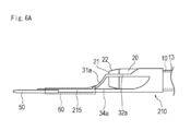
- ⁇ Modification 1> 6A is a side view showing the tip member 210 according to the first modification
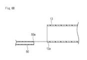
- FIG. 6B is a diagram simply showing the positional relationship between the guide wire insertion portion 50 and the cover member 13.
- the connecting portion 35 included in the distal end member 30 has a curved shape so as to be gradually separated from the rotating body 20 from the proximal end side toward the distal end side (see FIG. 2A).
- the connecting portion 215 extends substantially linearly along the axial direction.
- the medical device 1 can be further reduced in diameter, so that the delivery performance of the medical device 1 is improved.
- 6B for example, the tube wall 50a on the upper surface side of the guide wire insertion portion 50 and the tube wall 13a on the lower surface side of the cover member 13 covering the long member 10 are in the thickness direction (height direction).
- ⁇ Modification 2> 7A is a side view showing the tip member 220 according to the second modification
- FIG. 7B is a plan view showing the tip member 220 according to the second modification
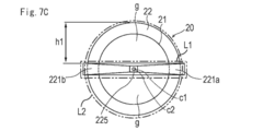
- FIG. 7C is a front view showing the tip member 220 according to the second modification. It is.
- the distal end member 220 is disposed on the guide portion 221, the proximal end side of the guide portion 221, the support portion 222 that supports the guide portion 221, the proximal end side of the support portion 222, and a cover material 13 and a base portion 223 fixed to the guide portion 221 and an extending portion 225 extending substantially linearly on the distal end side of the guide portion 221.
- the guide portion 221 has a first guide portion 221a and a second guide portion 221b that are bifurcated symmetrically from the axis c3 of the rotating body 20.
- the support part 222 includes a first support part 222a disposed between the first guide part 221a and the base part 223, and a second support part 222b disposed between the second guide part 221b and the base part 223.
- the guide part 221 is arranged so that the center position c2 of the guide part 221 in the height direction overlaps the center position c1 of the rotary body 20 in the height direction. Further, when viewed from the distal end side of the distal end member 220, the ratio of the portions where the guide portions 221a, 221b and the cutting portion 22 overlap in the circumferential direction is greater than the portion where the cutting portions 22 are exposed from the respective guide portions 221a, 221b in the circumferential direction. Is also getting smaller.
- the guide part 221 and the rotating body 20 have different shapes as viewed from the front end side of the tip member 30, and the outer peripheral length L1 of the guide part 221 is shorter than the outer peripheral length L2 of the rotating body 20.
- the guide portion 221 has a rectangular shape extending in the width direction when viewed from the distal end side of the distal end member 30.
- the base portion 223 is disposed so as to cover the outer periphery of the front end portion of the cover material 13 and is fixed to the cover material 13 in a state of covering the outer periphery.
- the extending part 225 disposed on the distal end side of the guide part 221 has a function of improving the delivery of the medical device 1 when the medical device 1 is moved in the blood vessel H or the like.
- a guide wire lumen in the extension part 225 and use the extension part 225 as a guide wire insertion part.
- the guide wire w may be inserted through the lumen 15 of the elongate member 10 as shown by a broken line in the drawing, or without inserting the lumen 15 of the elongate member 10. You may make it insert in the extension part 225 from the circumference
- the first guide part 221a and the second guide part 221b of the tip member 220 limit the effective cutting range to the range of the height h1. Therefore, by providing the medical device 1 with the distal end member 220 according to this modification, it is possible to suitably prevent the rotating body 20 from penetrating the blood vessel wall during treatment. Further, when the treatment is performed with the tip member 250 of the present modification, the debris D can be collected through the space g disposed on the upper surface side and the lower surface side of the rotating body 20, so the collection efficiency of the debris D can be improved. It becomes possible to improve.
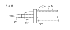
- ⁇ Modification 3> 8A is a side view showing a tip member 230 according to Modification Example 3
- FIG. 8B is a plan view showing tip member 230 according to Modification Example 3
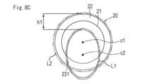
- FIG. 8C is a front view showing tip member 230 according to Modification Example 3. It is.
- the distal end member 230 is disposed on the guide portion 231, the proximal end side of the guide portion 231, the support portion 232 that supports the guide portion 231, the proximal end side of the support portion 232, and a cover material 13 and a base 233 fixed to 13.
- the support portion 232 arranges the center position c2 in the height direction of the guide portion 231 at a position displaced in the height direction from the center position c1 in the height direction of the rotating body 20 in a state where no external force is applied. .
- the guide portion 231 is disposed so as to overlap with the center position c1 in the height direction of the rotating body 20 and a part of the periphery of the rotating body 20 when viewed from the tip end side of the tip member 230. Further, the guide portion 231 and the rotating body 20 have different shapes when viewed from the distal end side of the distal end member 30, and the outer peripheral length L ⁇ b> 1 of the guide portion 231 is shorter than the outer peripheral length L ⁇ b> 2 of the rotating body 20.
- the guide portion 231 has a substantially elliptical shape in which a major axis is arranged in the height direction (vertical direction in the drawing) and a minor axis is arranged in the width direction (horizontal direction in the drawing). Has a shape. Further, as shown in FIG. 8A, the guide portion 231 has a shape in which the dimension in the height direction is gradually reduced from the proximal end portion toward the distal end portion.
- the cutting part 22 parts other than the part where the guide part 231 overlaps in the height direction are exposed from the guide part 231. Specifically, the portion along which the dimension along the short axis direction (left-right direction) is shorter than the longest portion is arranged so as to overlap the periphery of the rotating body 20. For this reason, the ratio of the part which the guide part 231 and the cutting part 22 overlap in the circumferential direction is smaller than the part which the cutting part 22 exposed from the guide part 231 in the circumferential direction. Moreover, since the long axis of the guide part 231 is arrange
- the support portion 232 is disposed on the bottom surface side of the rotating body 20.
- the support part 232 arrange
- the guide portion 231 of the tip member 230 limits the effective cutting range to the range of the height h1. Therefore, by providing the medical device 1 with the distal end member 230 according to this modification, it is possible to suitably prevent the rotating body 20 from penetrating the blood vessel wall during treatment.
- the support portion 232 arranges the center position c2 in the height direction of the guide portion 231 at a position displaced in the height direction from the center position c1 in the height direction of the rotation body 20, the guide portion 231 and the rotation body are arranged. It becomes possible to arrange a larger space g between the 20 tips. Therefore, the debris D can be collected more efficiently into the inner cavity 25 of the rotating body 20.
- the guide portion 231 has a smaller dimension in the height direction at the distal end than at the proximal end, the medical device 1 can be smoothly moved in the blood vessel H, and delivery is further improved. Is possible.
- the guide portion 231 is disposed so as to overlap with the center position c1 in the height direction of the rotating body 20 and a part of the peripheral edge of the rotating body 20 when viewed from the tip end side of the tip member 230. For this reason, since the function which guides the movement of the medical device 1 by the front end side of the rotary body 20 can be improved, it becomes possible to improve a delivery property further.
- the guide part 231 and the rotating body 20 have different shapes as viewed from the front end side of the tip member 30, and the outer peripheral length L1 of the guide part 231 is shorter than the outer peripheral length L2 of the rotating body 20. For this reason, it is possible to more reliably provide a portion where the guide portion 231 and the cutting portion 22 overlap and a portion where the cutting portion 22 is exposed from the guide portion 231.
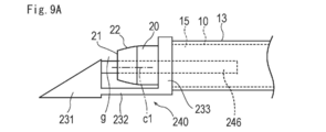
- ⁇ Modification 4> 9A is a side view showing a tip member 240 according to Modification Example 4
- FIG. 9B is a plan view showing tip member 240 according to Modification Example 4
- FIG. 9C is a front view showing tip member 240 according to Modification Example 4. It is.
- the tip member 240 according to this modification has substantially the same shape as the tip member 230 according to Modification 3 described above. However, it differs from the tip member 230 described above in that it includes a connecting member 246 connected to the guide portion 241.
- connection member 246 The distal end side of the connecting member 246 is connected to the proximal end surface of the guide portion 231, and the proximal end side is inserted into the lumen 15 of the long member 10.
- the connection member 246 can be made of, for example, a known resin material or metal material.
- a cross-sectional shape and a length dimension are not specifically limited, A hollow member may be sufficient and a solid member may be sufficient.
- the height of the guide portion 231 is set so that the support portion 232 is displaced in the height direction from the center position c1 in the height direction of the rotating body 20 when no external force is applied.
- the center position c2 of the direction is provided.
- the guide portion 231 is disposed so as to overlap with a center position c1 in the height direction of the rotating body 20 and a part of the peripheral edge of the rotating body 20 when viewed from the distal end side of the distal end member 240. Further, the outer peripheral length L1 of the guide portion 231 is shorter than the outer peripheral length L2 of the rotating body 20.
- the cutting part 22 parts other than the part where the guide part 231 overlaps in the height direction are exposed from the guide part 231. Specifically, the portion that is shorter than the longest dimension along the short axis direction (left-right direction) is disposed so as to overlap the periphery of the rotating body 20. For this reason, the ratio of the part which the guide part 231 and the cutting part 22 overlap in the circumferential direction is smaller than the part which the cutting part 22 exposed from the guide part 231 in the circumferential direction.
- the distal end member 240 maintains the connection between the guide portion 231 and the long member 10 by the connecting member 246 even when the support portion 232 or the base portion 233 is damaged. Even in the curved portion, it is possible to prevent the cutting portion 22 of the rotating body 20 from being exposed. Moreover, it becomes possible to prevent suitably the function of the guide part 231 from being impaired.
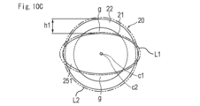
- FIG. 10A is a side view showing a tip member 250 according to Modification 5
- FIG. 10B is a plan view showing the tip member 250 according to Modification 5
- FIG. 10C is a front view showing the tip member 250 according to Modification 5. It is.
- the distal end member 250 includes a guide portion 251 and a support portion 252 that is disposed on the proximal end side of the guide portion 251 and supports the guide portion 251.
- the support portion 252 is inserted into the lumen 15 of the long member 10 and is fixed inside a hub 151 (see FIG. 1) provided in the hand operation portion 150.
- the guide portion 251 has a substantially elliptical shape in which a short axis is arranged in the height direction (vertical direction in the drawing) and a long axis is arranged in the width direction (horizontal direction in the drawing). Has a shape. Further, as shown in FIG. 10A, the guide portion 231 has a shape in which the dimension in the height direction is gradually reduced while being curved from the proximal end portion toward the distal end portion.
- the guide portion 251 is disposed so that the center position c ⁇ b> 2 of the rotating body 20 in the height direction overlaps the center position c ⁇ b> 2 of the guide portion 251 in the height direction.
- a portion of the cutting portion 22 other than the portion where the guide portion 251 overlaps in the height direction is exposed from the guide portion 251.
- the longest dimension along the long axis direction (left-right direction) is arranged so as to overlap the periphery of the rotating body 20.
- the guide portion 251 of the tip member 250 limits the effective cutting range to the height h1. Therefore, by providing the medical device 1 with the distal end member 250 according to this modification, it is possible to suitably prevent the rotating body 20 from penetrating the blood vessel wall during treatment. Further, when the treatment is performed with the tip member 250 of the present modification, the debris D can be collected through the space g disposed on the upper surface side and the lower surface side of the rotating body 20, so the collection efficiency of the debris D can be improved. It becomes possible to improve.
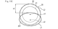
- FIG. 11A is a side view showing a tip member 260 according to Modification Example 6
- FIG. 11B is a plan view showing tip member 260 according to Modification Example 6
- FIG. 11C is a front view showing tip member 260 according to Modification Example 6. It is.
- the distal end member 260 is disposed on the proximal end side of the guide portion 261, the guide portion 261, the support portion 232 that supports the guide portion 261, and the proximal end side of the support portion 262. 13 and a base 263 fixed to 13.
- the guide portion 261 has a substantially elliptical shape in which a short axis is arranged in the height direction (vertical direction in the drawing) and a long axis is arranged in the width direction (horizontal direction in the drawing). Has a shape. Further, as shown in FIG. 11A, the guide portion 261 has a shape in which the dimension in the height direction gradually decreases from the proximal end portion toward the distal end portion.
- the support portion 262 is positioned in the height direction of the guide portion 231 at a position displaced in the height direction from the center position c1 in the height direction of the rotating body 20 when no external force is applied.
- the center position c2 is arranged.
- the guide portion 261 is disposed so as to overlap with the center position c1 in the height direction of the rotating body 20 and a part of the peripheral edge of the rotating body 20 when viewed from the tip end side of the tip member 260.
- a portion of the cutting portion 22 other than the portion where the guide portion 251 overlaps in the height direction is exposed from the guide portion 251.
- the longest dimension along the long axis direction (left-right direction) is arranged so as to overlap the periphery of the rotating body 20.
- the guide portion 261 of the tip member 260 limits the effective cutting range to the range of the height h1. Therefore, by providing the medical device 1 with the distal end member 260 according to this modification, it is possible to suitably prevent the rotating body 20 from penetrating the blood vessel wall during the treatment.
- FIG. 12 is a side view showing the tip member 270 according to the modified example 7. As shown in FIG. 12
- the distal end member 270 is disposed on the guide portion 271, the proximal end side of the guide portion 271, the support portion 272 that supports the guide portion 271, the proximal end side of the support portion 272, and a cover material 13 and a base 273 fixed to 13.
- the shape of the guide portion 271 in a side view is, for example, arranged in a substantially triangular shape in which the vertex 271a having the largest dimension in the height direction is arranged at a position shifted to the base end side. It is also possible. If comprised in this way, since the front-end
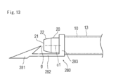
- FIG. 13 is a side view showing a tip member 280 according to Modification 8. As shown in FIG. 13
- the distal end member 280 is disposed on the guide portion 281, the base end side of the guide portion 281, the support portion 282 that supports the guide portion 281, the base end side of the support portion 282, and a cover material 13 and a base 283 fixed to 13.
- the guide portion 281 according to the present modification example has a sharper angle on the distal end side of the distal end portion than the guide portion 271 described in the above-described modification example 8, so that the delivery performance of the medical device 1 is further improved. .
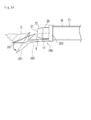
- FIG. 14 is a side view showing a tip member 290 according to Modification 9.
- the tip member 290 according to this modification has substantially the same shape as the tip member 280 according to Modification 8 described above. However, the difference is that the guide portion 281 and the support portion 282 are configured to be deformable so as to be separated from the rotating body 20 in contact with the narrowed portion S.
- the state when the tip member 290 is deformed is indicated by a two-dot chain line in the drawing. Since the guide portion 281 and the support portion 282 are configured to be deformed when contacting the narrowed portion S, an excessive pressing force is applied to the narrowed portion S when the narrowed portion S is cut. Can be prevented and treatment can be performed with an appropriate cutting force. Further, it is possible to suitably prevent the normal tissue from being damaged when the cutting unit 22 comes into contact with the normal tissue. Note that only one of the guide portion 281 and the support portion 282 may be deformable, and the other member may be formed of a relatively high rigidity member so that deformation does not occur due to contact with the narrowed portion S.
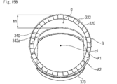
- ⁇ Modification 10> 15A is a side view showing the tip member 330 according to Modification Example 10, and FIG. 15B is a diagram simply showing the positional relationship between the guide portion 340 and the rotating body 320 as seen from the direction of the arrow 15B shown in FIG. 15A.
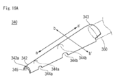
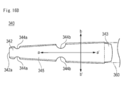
- 16A is a perspective view showing a guide part 340 according to Modification Example 10, and FIG. 16B is a plan view showing the guide part 340 according to Modification Example 10.
- the tip member 330 includes a guide portion 340 and a support portion 350 that supports the guide portion 340 in the height direction.
- the support part 350 forms a space g separating the guide part 340 and the rotary body 320 on the tip side of the rotary body 320.
- the guide portion 340 is composed of a plate-like member extending in the axial direction (the direction of the arrow a-a ′ in the drawing).
- the guide part 340 has a curved shape on one surface side (upper surface side in the illustrated example). Further, the guide portion 340 has a shape that becomes wider from the distal end portion 342 side to the proximal end portion 343 side of the guide portion 340 (the width dimension in the direction of the arrow bb ′ in the figure is from the distal end portion 342 side to the proximal end portion. The shape increases toward the H.343 side.
- the front end surface 342a of the guide portion 340 has a crescent-shaped shape as viewed from the front side (in the front view, the central portion on the upper side has the largest area, and both end sides The area gradually decreases toward the surface).
- the cross-sectional shape of each part in the axial direction of the guide part 340 (the cross-sectional shape of each part in the direction orthogonal to the axial direction) has a crescent-shaped shape, similar to the distal end surface 342a.
- a space 345 is formed on the inner surface side of the guide 340.
- the inner surface of the guide portion 340 has a crescent-shaped shape corresponding to the outer shape of the guide portion 340.
- the guide portion 340 is formed with a first groove portion 344a and a second groove portion 344b.
- the 1st groove part 344a is formed in the front end side rather than the 2nd groove part 344b.
- the base end part 343 of the guide part 340 is formed, for example, in a shape with a part cut away as shown in FIG. 16A.
- a predetermined fixing member 360 is connected to the base end portion 343 of the guide portion 340.
- the support part 350 has a first support part 350a and a second support part 350b.
- the 1st support part 350a is arrange
- the first support part 350a and the second support part 350b have a cylindrical shape extending in a direction intersecting the axial direction (the depth direction of the paper surface shown in FIG. 15A).
- the first support part 350a has a smaller outer diameter than the second support part 350b.
- the first support portion 350a of the support portion 350 is disposed in the first groove portion 344a of the guide portion 340.
- the first support part 350 a of the support part 350 is fixed to the first groove part 344 a of the guide part 340.
- the second support part 350 b of the support part 350 is disposed in the second groove part 344 b of the guide part 340.
- the second support part 350 b of the support part 350 is fixed to the second groove part 344 b of the guide part 340.
- the guide part 340 is arranged in a state of being curved toward the distal end side corresponding to the outer diameter difference between the first support part 350a and the second support part 350b.
- a rod-shaped member 370 extending in the axial direction is fixed to the outer surface of the cover material 13.
- a guide wire insertion portion 50 in which a guide wire lumen 55 is formed is disposed at the distal end portion of the rod-shaped member 370.
- the fixing member 360 connected to the guide portion 340 is inserted into the long member 10.
- the fixing member 360 prevents the guide portion 340 from falling off the long member 10 or the like.
- the distal end portion of the guide portion 340, the guide wire insertion portion 50, and the rod-like member 370 can be connected to each other via, for example, a covering member (for example, a known heat-shrinkable tube) 60.
- a covering member for example, a known heat-shrinkable tube
- the other member demonstrated by this modification can be connected by methods, such as welding and adhesion
- the rotating body 320 has a cutting part 322 formed with a blade surface (sawtooth blade surface) protruding in a concavo-convex shape on the tip side.
- the cutting part 322 can also be formed with the trepan blade surface (refer FIG. 3A) demonstrated in embodiment mentioned above, for example.
- the cutting surface 322 of the rotating body 320 is partially formed by the guide surface A1 (the guide portion 340 and the support portion 350) on one side (lower side in the illustrated example) of the distal end surface 342 a of the guide portion 340.
- a covered area is formed.
- the cutting portion of the rotating body 320 is formed by the guide portion 340 and the rod-shaped member 370.
- a guide surface A2 in which 322 is partially covered can be formed.
- the guide portion 340 is formed of a plate-like member, the guide surfaces A1 and A2 having a relatively large area in the left-right direction are provided below the guide portion 340 as shown in FIG. 15B. Can be formed. Further, even when the guide portion 340 is inadvertently displaced in the vertical direction on FIG. 15B during the treatment for the constricted portion S, the end portion in the width direction of the guide portion 340 ( 15B is supported in contact with the inner peripheral surface of the rotator 320, so that the displacement of the guide portion 340 can be suppressed.
- the constricted portion S can be cut into a crescent shape (peel shape) having a relatively small thickness. Thereby, it is possible to prevent the excision piece (debris D) of the narrowed portion S from being clogged inside the long member 10.
- each member rotary body 320, guide part 340, support part 350, etc.
- the resin material or metal material exemplified in the above-described embodiment or other modifications may be used. it can.
- the specific shapes of the guide portion 340 and the support portion 350 are not limited to the illustrated shapes, and can be changed as appropriate.
- the guide portion 340 can be formed of a flat plate-like member having a rectangular cross section, or can be formed of a plate-like member having a different cross-sectional shape at each portion in the axial direction.
- the guide portion 340 may have a shape other than the crescent shape, and the curvature and the like in the curved shape can be appropriately changed.
- the support portion 350 may be composed of only one member, or may be composed of three or more members. .
- the shape, structure, and the like of the tip member include at least one guide portion disposed on the tip side of the rotating body with a space therebetween, and a support portion that supports the guide portion. It does not specifically limit as long as it is provided, and is not limited to the configuration of the tip member described in the embodiment and the modification.
- a living body lumen to which a medical device and a treatment method are applied is not limited to a blood vessel, and may be, for example, a vascular tube, a urinary tract, a bile duct, a fallopian tube, a hepatic tube, or the like, or a cutting target.
- the object is not limited to a stenosis or a blockage.
- the treatment for cutting the stenosis portion formed in a part of the wall of the living body lumen in the circumferential direction is exemplified, but depending on the shape of the stenosis portion, the position in the circumferential direction to be formed, etc.
- the use of the medical device is not limited.
Landscapes
- Health & Medical Sciences (AREA)
- Surgery (AREA)
- Life Sciences & Earth Sciences (AREA)
- Medical Informatics (AREA)
- Animal Behavior & Ethology (AREA)
- Engineering & Computer Science (AREA)
- Biomedical Technology (AREA)
- Heart & Thoracic Surgery (AREA)
- Veterinary Medicine (AREA)
- Molecular Biology (AREA)
- Nuclear Medicine, Radiotherapy & Molecular Imaging (AREA)
- General Health & Medical Sciences (AREA)
- Public Health (AREA)
- Vascular Medicine (AREA)
- Orthopedic Medicine & Surgery (AREA)
- Oral & Maxillofacial Surgery (AREA)
- Pathology (AREA)
- Surgical Instruments (AREA)
- Media Introduction/Drainage Providing Device (AREA)
Priority Applications (2)
| Application Number | Priority Date | Filing Date | Title |
|---|---|---|---|
| CN201780011370.7A CN108697434B (zh) | 2016-02-15 | 2017-02-14 | 医疗器械 |
| JP2018500132A JP6806764B2 (ja) | 2016-02-15 | 2017-02-14 | 医療デバイス |
Applications Claiming Priority (2)
| Application Number | Priority Date | Filing Date | Title |
|---|---|---|---|
| JP2016-026339 | 2016-02-15 | ||
| JP2016026339 | 2016-02-15 |
Publications (1)
| Publication Number | Publication Date |
|---|---|
| WO2017141924A1 true WO2017141924A1 (ja) | 2017-08-24 |
Family
ID=59559415
Family Applications (1)
| Application Number | Title | Priority Date | Filing Date |
|---|---|---|---|
| PCT/JP2017/005379 WO2017141924A1 (ja) | 2016-02-15 | 2017-02-14 | 医療デバイス |
Country Status (4)
| Country | Link |
|---|---|
| US (1) | US10874423B2 (zh) |
| JP (2) | JP6806764B2 (zh) |
| CN (2) | CN113855176A (zh) |
| WO (1) | WO2017141924A1 (zh) |
Cited By (1)
| Publication number | Priority date | Publication date | Assignee | Title |
|---|---|---|---|---|
| WO2018221683A1 (ja) * | 2017-05-31 | 2018-12-06 | テルモ株式会社 | 医療デバイス |
Families Citing this family (2)
| Publication number | Priority date | Publication date | Assignee | Title |
|---|---|---|---|---|
| CN107348990B (zh) * | 2017-08-25 | 2020-04-07 | 蔡改贫 | 超声除栓系统 |
| CN116196062B (zh) * | 2023-04-25 | 2023-08-11 | 上海宇度医学科技股份有限公司 | 宫腔镜下黏膜下肌瘤切除装置 |
Citations (3)
| Publication number | Priority date | Publication date | Assignee | Title |
|---|---|---|---|---|
| JP2013513442A (ja) * | 2009-12-11 | 2013-04-22 | タイコ ヘルスケア グループ リミテッド パートナーシップ | 改良された物質捕捉能率を有する物質除去デバイスおよび方法 |
| JP2014533147A (ja) * | 2011-10-13 | 2014-12-11 | アセローメド, インコーポレイテッド | アテレクトミー装置、システム、および方法 |
| JP2015536802A (ja) * | 2012-12-12 | 2015-12-24 | コヴィディエン リミテッド パートナーシップ | 身体管腔のための組織除去カテーテル |
Family Cites Families (17)
| Publication number | Priority date | Publication date | Assignee | Title |
|---|---|---|---|---|
| US4950277A (en) * | 1989-01-23 | 1990-08-21 | Interventional Technologies, Inc. | Atherectomy cutting device with eccentric wire and method |
| AU5143000A (en) * | 1999-05-18 | 2000-12-05 | Vascular Innovations, Inc. | Implantable medical device such as an anastomosis device |
| US7494497B2 (en) * | 2003-01-02 | 2009-02-24 | Boston Scientific Scimed, Inc. | Medical devices |
| US8246640B2 (en) * | 2003-04-22 | 2012-08-21 | Tyco Healthcare Group Lp | Methods and devices for cutting tissue at a vascular location |
| CA2572504A1 (en) * | 2004-07-01 | 2006-01-19 | Biovision Ag | Intracorneal lens placement method and apparatus |
| US20070032746A1 (en) * | 2005-01-10 | 2007-02-08 | Stereotaxis, Inc. | Guide wire with magnetically adjustable bent tip and method for using the same |
| US20070088230A1 (en) * | 2005-09-06 | 2007-04-19 | Fmd Co., Ltd | Medical instrument and medical equipment for treatment, and rotational handle device |
| US20080045986A1 (en) * | 2006-06-30 | 2008-02-21 | Atheromed, Inc. | Atherectomy devices and methods |
| DE102006047204B4 (de) * | 2006-10-05 | 2015-04-23 | Erbe Elektromedizin Gmbh | Rohrschaftinstrument |
| JP2008295901A (ja) * | 2007-06-01 | 2008-12-11 | Wakayoshi Seisakusho Co Ltd | 切除骨採取具 |
| WO2008149822A1 (ja) * | 2007-06-01 | 2008-12-11 | Wakayoshi Seisakusho Co., Ltd. | 医療用切削具及びそのガイド部材並びに切除骨採取具 |
| JP5393684B2 (ja) * | 2008-08-11 | 2014-01-22 | テルモ株式会社 | 医療用具 |
| US20100087780A1 (en) * | 2008-10-03 | 2010-04-08 | Cook Incorporated | Wire Guide having Variable Flexibility and Method of Use Thereof |
| BR112013009835A2 (pt) * | 2010-10-28 | 2016-07-26 | Covidien Lp | dispositivo para a remoção de material e método de uso |
| JP5917279B2 (ja) * | 2012-05-07 | 2016-05-11 | 株式会社グッドマン | 医療用シャフトおよび医療用器具 |
| US20150314108A1 (en) | 2012-12-18 | 2015-11-05 | Sumitomo Bakelite Co., Ltd. | Medical device |
| WO2015042190A2 (en) | 2013-09-18 | 2015-03-26 | Xablecath Inc. | Systems and methods for crossing and treating an occlusion |
-
2017
- 2017-02-14 CN CN202111281283.8A patent/CN113855176A/zh active Pending
- 2017-02-14 CN CN201780011370.7A patent/CN108697434B/zh active Active
- 2017-02-14 JP JP2018500132A patent/JP6806764B2/ja active Active
- 2017-02-14 WO PCT/JP2017/005379 patent/WO2017141924A1/ja active Application Filing
- 2017-02-15 US US15/432,978 patent/US10874423B2/en active Active
-
2020
- 2020-12-04 JP JP2020201743A patent/JP7044855B2/ja active Active
Patent Citations (3)
| Publication number | Priority date | Publication date | Assignee | Title |
|---|---|---|---|---|
| JP2013513442A (ja) * | 2009-12-11 | 2013-04-22 | タイコ ヘルスケア グループ リミテッド パートナーシップ | 改良された物質捕捉能率を有する物質除去デバイスおよび方法 |
| JP2014533147A (ja) * | 2011-10-13 | 2014-12-11 | アセローメド, インコーポレイテッド | アテレクトミー装置、システム、および方法 |
| JP2015536802A (ja) * | 2012-12-12 | 2015-12-24 | コヴィディエン リミテッド パートナーシップ | 身体管腔のための組織除去カテーテル |
Cited By (4)
| Publication number | Priority date | Publication date | Assignee | Title |
|---|---|---|---|---|
| WO2018221683A1 (ja) * | 2017-05-31 | 2018-12-06 | テルモ株式会社 | 医療デバイス |
| JPWO2018221683A1 (ja) * | 2017-05-31 | 2020-04-02 | テルモ株式会社 | 医療デバイス |
| JP7244416B2 (ja) | 2017-05-31 | 2023-03-22 | テルモ株式会社 | 医療デバイス |
| US11925383B2 (en) | 2017-05-31 | 2024-03-12 | Terumo Kabushiki Kaisha | Medical device |
Also Published As
| Publication number | Publication date |
|---|---|
| JP2021037366A (ja) | 2021-03-11 |
| CN108697434A (zh) | 2018-10-23 |
| JPWO2017141924A1 (ja) | 2018-12-06 |
| CN113855176A (zh) | 2021-12-31 |
| JP7044855B2 (ja) | 2022-03-30 |
| US20170231657A1 (en) | 2017-08-17 |
| US10874423B2 (en) | 2020-12-29 |
| JP6806764B2 (ja) | 2021-01-06 |
| CN108697434B (zh) | 2021-11-19 |
Similar Documents
| Publication | Publication Date | Title |
|---|---|---|
| JP7044855B2 (ja) | 医療デバイス | |
| US10856898B2 (en) | Foreign object removal device | |
| US11000304B2 (en) | Medical device and treatment method | |
| WO2018052121A1 (ja) | 医療デバイス | |
| EP3337551B1 (en) | Double concentric guidewire | |
| JP6964082B2 (ja) | 医療デバイス | |
| US11259836B2 (en) | Medical device and treatment method | |
| JP2023181473A (ja) | 医療デバイス | |
| JP6966620B2 (ja) | 医療デバイス | |
| JP6105931B2 (ja) | カテーテルハブ | |
| WO2018051893A1 (ja) | 医療デバイス | |
| WO2023199568A1 (ja) | 穿刺デバイス | |
| US20240180585A1 (en) | Medical device | |
| US11925383B2 (en) | Medical device | |
| WO2018052123A1 (ja) | 医療デバイス |
Legal Events
| Date | Code | Title | Description |
|---|---|---|---|
| 121 | Ep: the epo has been informed by wipo that ep was designated in this application |
Ref document number: 17753181 Country of ref document: EP Kind code of ref document: A1 |
|
| ENP | Entry into the national phase |
Ref document number: 2018500132 Country of ref document: JP Kind code of ref document: A |
|
| NENP | Non-entry into the national phase |
Ref country code: DE |
|
| 122 | Ep: pct application non-entry in european phase |
Ref document number: 17753181 Country of ref document: EP Kind code of ref document: A1 |