WO2017141623A1 - Toilettes, et procédé de fabrication de toilettes - Google Patents
Toilettes, et procédé de fabrication de toilettes Download PDFInfo
- Publication number
- WO2017141623A1 WO2017141623A1 PCT/JP2017/001965 JP2017001965W WO2017141623A1 WO 2017141623 A1 WO2017141623 A1 WO 2017141623A1 JP 2017001965 W JP2017001965 W JP 2017001965W WO 2017141623 A1 WO2017141623 A1 WO 2017141623A1
- Authority
- WO
- WIPO (PCT)
- Prior art keywords
- support
- toilet
- pair
- bowl
- portions
- Prior art date
Links
Images


Classifications
-
- E—FIXED CONSTRUCTIONS
- E03—WATER SUPPLY; SEWERAGE
- E03D—WATER-CLOSETS OR URINALS WITH FLUSHING DEVICES; FLUSHING VALVES THEREFOR
- E03D11/00—Other component parts of water-closets, e.g. noise-reducing means in the flushing system, flushing pipes mounted in the bowl, seals for the bowl outlet, devices preventing overflow of the bowl contents; devices forming a water seal in the bowl after flushing, devices eliminating obstructions in the bowl outlet or preventing backflow of water and excrements from the waterpipe
- E03D11/13—Parts or details of bowls; Special adaptations of pipe joints or couplings for use with bowls, e.g. provisions in bowl construction preventing backflow of waste-water from the bowl in the flushing pipe or cistern, provisions for a secondary flushing, for noise-reducing
- E03D11/14—Means for connecting the bowl to the wall, e.g. to a wall outlet
- E03D11/143—Mounting frames for toilets and urinals
Definitions
- the present invention relates to a toilet and a method for manufacturing the toilet.
- Patent Document 1 discloses an installation structure of a wall-mounted toilet.
- the toilet bowl is fixed to a bracket fixed to the wall surface.
- the bracket does not look good because the part supporting the toilet is exposed. Further, in the toilet installation structure disclosed in Patent Document 1, in order to improve the appearance, the bracket is covered with an undercover supported by the toilet. There is a need to.
- the present invention has been made in view of the above circumstances, and an object of the present invention is to provide a toilet with good workability and a method for manufacturing the toilet, in which a portion of the support frame that supports the toilet is difficult to see in appearance.
- the toilet of one aspect according to the present invention has the following characteristics.
- the toilet includes a toilet body in which a bowl portion is formed, and a support frame that can be fixed to a vertical surface.
- the toilet main body includes a support housing portion in which a housing space is formed.
- the support frame includes a support that is disposed in the storage space and supports the support storage unit. An insertion opening for inserting the support into the storage space is formed in the support storage.
- the method for manufacturing a toilet of one aspect according to the present invention has the following characteristics.
- the toilet includes a toilet body in which a bowl portion is formed, and a support frame that can be fixed to a vertical surface.
- the toilet main body includes a support housing portion in which a housing space is formed.
- the support frame includes a support that is disposed in the storage space and supports the support storage unit. An insertion opening is formed in the support housing portion. The support is inserted into the storage space from the insertion opening.
- FIG. 1 is a perspective view showing a state in which a toilet according to the first embodiment of the present invention is installed.
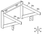
- FIG. 2 is a perspective view of the support frame of the toilet bowl.
- FIG. 3 is a horizontal sectional view showing a state in which the toilet bowl is installed.
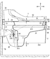
- FIG. 4 shows a state in which the toilet bowl is installed, and is a cross-sectional view along the vertical plane.
- FIG. 5 is an enlarged view of a portion A in FIG.
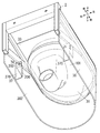
- FIG. 6 is a perspective view as seen from the lower side of the toilet bowl, and is a view in which illustrations of the rear part of the toilet bowl, the toilet seat, the toilet lid, and the like are omitted.
- 7 is a cross-sectional view taken along line BB in FIG. FIG.
- FIG. 8A is a cross-sectional view of a portion corresponding to FIG. 5 in the toilet bowl according to Modification 1-1.
- FIG. 8B is a cross-sectional view of a portion corresponding to FIG. 5 in the toilet bowl according to Modification 1-2.
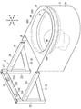
- FIG. 9 is a perspective view of a toilet support frame according to Modification 1-3.
- FIG. 10 is a perspective view of a toilet according to an embodiment of the present invention.
- FIG. 11A is a perspective view of the support frame of the toilet bowl.
- FIG. 11B is a cross-sectional view of a support portion of the same support frame.
- FIG. 12A is a horizontal sectional view of the toilet bowl.
- FIG. 12B is a cross-sectional view perpendicular to the longitudinal direction of the support portion of the toilet according to the embodiment.
- FIG. 13 is sectional drawing along the vertical plane of the toilet bowl same as the above.
- FIG. 14 is a perspective view of the toilet main body in which the bowl portion and the trap portion of the toilet bowl are not shown.
- FIG. 15 is an exploded perspective view illustrating attachment of the toilet main body to the support frame.
- FIG. 16 is a perspective view of a support frame of Modification 2-1.
- FIG. 17A is a cross-sectional view of the periphery of the mounting portion of modification 2-2-1.
- FIG. 17B is a cross-sectional view of the periphery of the mounting portion of modification 2-2-2.
- FIG. 17C is a cross-sectional view of the periphery of the placement portion of modification 2-3.
- FIG. 18 is a cross-sectional view of the periphery of the mounting portion of modification 2-2-4.
- FIG. 19A is a cross-sectional view of the periphery of the placement portion of modification 2-3-1.
- FIG. 19B is a cross-sectional view of the periphery of the placement portion of modification 2-3-2.
- FIG. 20 is a cross-sectional view of the periphery of the placement portion of modification 2-4-1.
- FIG. 21 is a cross-sectional view of the periphery of the placement portion of modification 2-4-2.
- FIG. 22 is an exploded perspective cross-sectional view of the support portion and the rim portion of Modification 2-5-1.
- FIG. 23 is an exploded perspective cross-sectional view of a support portion and a rim portion of Modification 2-5-2.
- FIG. 24 is a cross-sectional view along the vertical plane of the toilet of modification 2-6.
- FIG. 25A is a perspective view of a rail of Modification 2-7-1.
- FIG. 25B is a cross-sectional view of a rail according to a modification of the above.
- FIG. 26A is a perspective view of a portion where a rail fixing portion according to a modification of the above is provided.
- FIG. 26B is a cross-sectional view of a portion where the rail fixing portion of the modified example is provided.
- FIG. 26C is a cross-sectional view of another example of the portion where the rail fixing portion of the modified example is provided.
- FIG. 27A is a cross-sectional view before the rail is inserted, illustrating the manufacture of the toilet body of the modified example of the above.
- FIG. 27B is a cross-sectional view after inserting the rail, illustrating the manufacture of the toilet body of the modified example of the above.
- FIG. 27C is a cross-sectional view of a state in which the skirt portion is welded to explain the manufacture of the toilet body of the modified example.
- FIG. 28A is a cross-sectional view of the periphery of the placement portion of modification 2-7-2.
- FIG. 28B is a cross-sectional view of the periphery of the placement portion of modification 2-7-3.
- FIG. 28C is a cross-sectional view of the periphery of the placement portion of modification 2-7-4.
- FIG. 28D is a cross-sectional view of the periphery of the placement portion of modification 2-7-5.
- FIG. 29A is a cross-sectional view of the periphery of the placement portion of modification 2-7-6.
- FIG. 29B is a cross-sectional view of the periphery of the placement portion of modification 2-7-7.
- FIG. 30A is a cross-sectional view of the periphery of the placement portion of modification 2-7-8.
- FIG. 30B is a cross-sectional view of the periphery of the placement portion of modification 2-7-9.
- FIG. 31 is a cross-sectional view of the periphery of the placement portion of modification 2-7-10.
- the first embodiment, the modification of the first embodiment, the second embodiment, and the modification of the second embodiment described below relate to a toilet and a method for manufacturing the toilet, and are specifically attached to a vertical surface such as a wall surface.
- the present invention relates to a toilet and a method for manufacturing the toilet.
- the toilet bowl 1 is a toilet bowl 1 in which the installation surface is a vertical plane 70 along the vertical direction and the horizontal direction, and as shown in FIG. A toilet attached to the surface 70. That is, the toilet 1 is a wall-mounted toilet.
- the front-rear direction is determined based on the user seated on the toilet 1. That is, as shown in FIG. 1, the direction in which the toilet 1 protrudes from the vertical surface 70 is defined as the front, and the direction from the toilet 1 toward the vertical surface 70 is defined as the rear. Moreover, let the direction parallel to the front and back be the front-back direction, and let the direction orthogonal to the front-back direction and a horizontal plane be the left-right direction.
- the toilet bowl 1 is arranged away from the floor surface 71. For this reason, the user can easily clean the floor surface 71 located below the toilet bowl 1.
- the toilet 1 includes a toilet body 3 and a support frame 2 that can be fixed to the vertical surface 70.
- the toilet body 3 is supported by the support frame 2. That is, since the toilet bowl 1 of this embodiment is arrange
- the support frame 2 is used to attach the toilet body 3 to the vertical surface 70.
- the support frame 2 is formed of, for example, a metal such as iron, stainless steel, or aluminum, FRP, wood, or the like so as to withstand the load applied when the user is seated on the toilet 1.
- the support frame 2 includes a fixed body 21 and a support body 20 that protrudes forward from the fixed body 21.
- the fixed body 21 is a part fixed to a vertical surface 70 such as a wall surface shown in FIG.
- the fixed body 21 is fixed to the vertical surface 70 with the rear surface along the vertical surface 70.
- the vertical surface 70 does not mean only a strict vertical surface, but is included in the category of “vertical surface” as long as it is a surface along the vertical direction and the horizontal direction.
- the vertical surface 70 includes a slightly inclined surface and also includes a slightly inclined surface.
- the vertical surface 70 may not be a flat surface, and may be a surface with unevenness.
- the fixed body 21 of this embodiment has a pair of vertical bodies 22 and a horizontal body 23 that connects the pair of vertical bodies 22 as shown in FIG.
- the rear surface of the pair of vertical bodies 22 and the rear surface of the horizontal body 23 are flush with each other, and the rear surface of the pair of vertical bodies 22 and the rear surface of the horizontal body 23 constitute the rear surface of the fixed body 21.
- Each of the pair of vertical bodies 22 of the present embodiment is configured by a hollow pipe extending in the vertical direction.
- the pair of vertical bodies 22 are separated in the left-right direction.
- the horizontal body 23 is disposed between the upper ends of the pair of vertical bodies 22.
- the horizontal body 23 is fixed to a pair of vertical bodies 22.
- the horizontal body 23 connects the upper ends of the pair of vertical bodies 22.
- the cross-sectional shape orthogonal to the horizontal direction of the horizontal body 23 of the present embodiment is substantially C-shaped.
- the horizontal body 23 of the present embodiment includes a fixed plate 232 and a pair of reinforcing pieces 233.
- the fixed plate 232 is formed in a plate shape orthogonal to the front-rear direction and extending in the left-right direction.
- the rear surface of the horizontal body 23 is constituted by the rear surface of the fixed plate 232.
- the pair of reinforcing pieces 233 protrude forward from both ends of the fixing plate 232 in the vertical direction.
- the pair of reinforcing pieces 233 suppress the deformation of the fixing plate 232.
- the horizontal body 23 of the present embodiment is provided with a plurality of fixing tool insertion holes 231.
- the fixing plate 232 is formed with a plurality of fixing tool insertion holes 231 arranged in the left-right direction. Each of the plurality of fixing tool insertion holes 231 passes through the fixing plate 232 in the front-rear direction.
- a plurality of fixing tools 73 (see FIG. 3) used for fixing the fixing body 21 to the vertical surface 70 are passed through the plurality of fixing tool insertion holes 231, respectively.
- the fixed body 21 is attached to the vertical surface 70 using a plurality of fixing tools 73 in a state where the rear surface is disposed along the vertical surface 70.
- Each of the plurality of fixing tools 73 of the present embodiment is a screw tool made of screws or bolts. That is, the fixed body 21 (horizontal body 23) is attached to the vertical surface 70 by screwing the fixing tools 73 passed through the fixing tool insertion holes 231 into the vertical surface 70.
- a washer may be sandwiched between the head of the fixing tool 73 and the fixing plate 232. .
- a flat washer or a spring washer is exemplified.
- the fixing plate 232 of the present embodiment has a plurality of opening peripheral portions 234 that constitute the peripheral portion of the fixing tool insertion hole 231.
- Each opening peripheral portion 234 is formed thicker than other portions of the fixed plate 232 excluding the plurality of opening peripheral portions 234. For this reason, the contact area between the shaft portion of the fixing tool 73 and the fixing plate 232 tends to be a certain area or more. Therefore, an external force applied to the fixing plate 232 from the fixing tool 73 can be dispersed while reducing the material cost by using the thinnest possible material as the fixing plate 232, and the fixing plate 232 is hardly broken.
- each opening peripheral edge 234 is thicker than the length of one pitch of the thread of the male screw of the corresponding fixing tool 73.
- each opening peripheral portion 234 is the same as the outer diameter of the washer or larger than the outer diameter of the washer. In this case, all or most of the washer is easily sandwiched between the opening peripheral edge 234 and the head of the fixing tool 73, and the fixing body 21 is easily fixed firmly to the vertical surface 70.
- each fixing tool insertion hole 231 of the present embodiment is substantially the same as the outer diameter of the shaft portion of the fixing tool 73.
- a wall-mounted toilet made of earthenware the wall surface and the toilet body made of earthenware are connected by a screw.
- the shaft of the screw tool and the insertion hole of the toilet body A cushioning material may be arranged between the peripheral surface.
- the cushioning material when the user sits on the toilet seat, the cushioning material is elastically deformed, so that the toilet body moves easily so as to sink slightly.
- the support frame 2 that is not easily damaged is interposed between the vertical surface 70 and the toilet body 3, and is attached to the thread of the fixing tool 73 screwed to the vertical surface 70.
- the contact portion is configured to be the support frame 2. For this reason, even if a load is applied to the toilet body 3, the toilet body 3 does not contact the fixing tool 73, and the toilet body 3 is not easily damaged or cracked.
- the diameter of the fixing tool insertion hole 231 is substantially the same as the outer diameter of the shaft part of the fixing tool 73, the toilet 1 of the present embodiment is unlikely to sink when the user is seated.
- each fixing tool 73 is not limited to a screw tool, and may be a rivet or a nail, for example.
- the support 20 protrudes forward from the upper part of the fixed body 21.
- the support 20 is a part that supports the toilet body 3 in the support frame 2.
- the support body 20 of the present embodiment includes a pair of support portions 24 extending in the front-rear direction and a front side connection portion (connection portion) 25 that connects the front end portions of the pair of support portions 24.
- Each of the pair of support portions 24 has a linear shape extending in the front-rear direction in plan view.
- the pair of support portions 24 protrude from the pair of vertical bodies 22 toward the front.
- the pair of support portions 24 are separated in the left-right direction.
- the front side connecting part 25 is formed in a semicircular arc shape when viewed from above (hereinafter referred to as a plan view).
- Each support part 24 of this embodiment has the upper horizontal piece 244, the lower horizontal piece 245, and the vertical piece 243, as shown in FIG.
- the upper horizontal piece 244 and the lower horizontal piece 245 are spaced apart in the vertical direction.
- the upper surface of the upper horizontal piece 244 constitutes the upper surface of the support portion 24.
- the upper horizontal piece 244 and the lower horizontal piece 245 are connected via a vertical piece 243.
- the upper horizontal piece 244 and the lower horizontal piece 245 protrude from the upper and lower ends of the vertical piece 243 toward the inside (the other support portion 24).
- Each support part 24 of this embodiment further has a vertical piece 246.
- the vertical piece 246 connects the ends of the upper horizontal piece 244 and the lower horizontal piece 245 opposite to the vertical piece 243.
- the pair of support portions 24 and the front side connection portion 25 of the present embodiment are configured by a continuous U-shaped square pipe in a plan view.
- the upper surface of each of the pair of support portions 24 and the upper surface of the front connection portion 25 are horizontal and flat surfaces.
- the flat upper surface of the pair of support portions 24 and the flat upper surface of the front side connecting portion 25 are flush with each other.
- the support frame 2 of the present embodiment further includes a pair of left and right reinforcing portions 8.
- the pair of reinforcing portions 8 support the pair of support portions 24 one to one.
- Each of the pair of reinforcing portions 8 of the present embodiment is located below the corresponding support portion 24.
- Each of the pair of support portions 24 of the present embodiment is connected to the fixed body 21 via the corresponding reinforcing portion 8.
- each reinforcing portion 8 is a material (bar reinforcement) 81 inclined with respect to the horizontal direction.
- Each reinforcing portion 8 has one end connected to the front end of the corresponding support 24 and the other end connected to the lower end of the corresponding vertical body 22, and the vertical 22 corresponding to the corresponding support 24. It is bridged between. That is, the reinforcement part 8 located on the left side connects the lower end part of the vertical body 22 located on the left side and the support part 24 located on the left side.
- the reinforcement part 8 located in the right side has connected the lower end part of the vertical body 22 located in the right side, and the support part 24 located in the right side.
- Each reinforcing part 8 supports the corresponding support part 24 from below.
- Each reinforcing portion 8 reinforces the support frame 2 while maintaining the relative positional relationship between the corresponding vertical body 22 and the corresponding support portion 24.
- the support frame 2 of the present embodiment further includes a fixing portion 200 to which the toilet body 3 is fixed.
- the fixing part 200 has a pair of left and right fixing pieces 201.
- the pair of fixed pieces 201 are provided on the pair of reinforcing portions 8 in a one-to-one relationship.
- Each of the pair of fixed pieces 201 protrudes downward from the reinforcing portion 8.
- Each fixed piece 201 includes a plate-like vertical piece 202 having a horizontal cross-sectional shape of L shape and a thickness direction parallel to the front-rear direction.
- the toilet body 3 constitutes the main body of the toilet 1.
- the toilet body 3 of the present embodiment is made of synthetic resin.
- the toilet body 3 is supported by the support frame 2 and is disposed in a state of protruding forward from the vertical surface 70.
- the toilet body 3 of the present embodiment includes a bowl portion 31, a rim portion 33, and a skirt portion (skirt) 36.
- Each of the bowl part 31, the rim part 33, and the skirt part 36 of this embodiment is made of synthetic resin.
- the skirt portion 36 has a width in the vertical direction.
- the skirt portion 36 is formed in a U-shape that opens rearward in plan view.
- the skirt portion 36 covers the outside of the bowl portion 31.
- An opening 362 is formed on the lower surface of the skirt portion 36.
- the rim portion 33 connects the upper end portion of the bowl portion 31 and the upper end portion of the skirt portion 36.
- the upper surface of the rim portion 33 constitutes the upper surface of the toilet body 3.
- the bowl part 31 is a part for receiving filth (a urine or a stool discharged by a user).
- the bowl portion 31 is formed in a bowl shape that opens upward from the toilet body 3.
- the bowl part 31 has an upper opening 311 and a lower opening 312.
- the upper opening 311 is formed at the upper end (upper surface) of the bowl portion 31.
- the bowl portion 31 opens upward from the upper opening portion 311.
- the lower opening 312 is formed at the lower end of the bowl 31.
- the lower opening 312 opens rearward, and the lower end of the bowl 31 opens from the lower opening 312 rearward.
- a support housing portion 30 that houses the support 20 is provided at the upper end of the bowl portion 31.
- the support storage part 30 of this embodiment is configured by a part of the rim part 33 and a part of the skirt part 36.
- the rim portion 33 is provided at the upper end portion of the bowl portion 31. As shown in FIG. 5, the rim portion 33 has an inner peripheral portion 330 and a lateral piece portion (lateral surface portion) 336. The inner peripheral part 330 and the horizontal piece part 336 are integrally formed.
- the inner peripheral portion 330 extends over the entire length of the bowl portion 31 in the circumferential direction, and is formed in an annular shape in plan view.
- the inner peripheral portion 330 extends upward from the upper end portion of the bowl portion 31.
- the inner peripheral portion 330 is bent so that the middle portion in the vertical direction protrudes inward.
- the inner periphery 330 has a lower inner periphery 332 and an upper inner periphery 333.
- the lower inner peripheral portion 332 extends from the peripheral edge of the upper opening 311 of the bowl portion 31 toward the inside (inner peripheral side) and obliquely upward.
- the lower inner peripheral portion 332 is curved so as to be concave upward in a cross section orthogonal to the circumferential direction.
- the lower end portion of the lower inner peripheral portion 332 is joined to the peripheral portion of the upper opening 311 of the bowl portion 31 by welding. Thereby, the rim part 33 and the bowl part 31 are connected.
- the upper inner peripheral portion 333 extends from the inner end of the lower inner peripheral portion 332 toward the outer side (outer peripheral side) obliquely upward, and is inclined with respect to the vertical direction so as to be positioned outward as it goes upward. Yes.
- the horizontal piece portion 336 extends outward from the upper end portion of the inner peripheral portion 330 along the horizontal plane.
- the horizontal piece portion 336 is formed over the entire length of the inner peripheral portion 330 in the circumferential direction.
- the lower surface of the horizontal piece 336 is a horizontal flat surface.
- the upper end of the skirt portion 36 is joined to the outer peripheral end portion of the horizontal piece portion 336 of the rim portion 33. This joining is performed by welding. Thereby, the skirt part 36 and the rim
- the upper end portion of the skirt portion 36 constitutes an outer peripheral portion 360 that faces the inner peripheral portion 330.
- the outer peripheral portion 360 extends downward from the outer end portion of the horizontal piece portion 336.
- the support storage part 30 of the present embodiment includes an inner peripheral part 330, a horizontal piece part 336, and an outer peripheral part 360.
- the storage space 305 is located in a region 101 surrounded by the bowl portion 31, the skirt portion 36, and the rim portion 33, and is a part of the region 101.
- An insertion opening 306 that opens the storage space 305 downward is formed on the lower surface of the support storage unit 30.
- the insertion opening 306 of the present embodiment is formed between the lower end portion of the inner peripheral portion 330 (the lower end portion of the lower inner peripheral portion 332) and the skirt portion 36 located on the outer side.
- the storage space 305 opens downward through the insertion opening 306.
- the support 20 of the support frame 2 is disposed in the storage space 305 of the support storage 30.
- the support 20 is covered with an inner peripheral portion 330, a lateral piece portion 336, and an outer peripheral portion 360.
- the width w1 of each of the pair of support portions 24 and the front side connection portion 25 of the support 20 is smaller than the width w2 of the corresponding portion in the insertion opening 306. Therefore, the support 20 can be inserted into the storage space 305 of the support storage 30 from below through the insertion opening 306.
- the support 20 is disposed along the inner periphery 330.
- a portion of the horizontal piece portion 336 excluding a portion located behind the bowl portion 31 (that is, the front portion and the left and right portions) is in contact with the upper surface of the support 20. Accordingly, the horizontal piece 336 is supported from below by the support 20 (the pair of support parts 24 and the front connection part 25) in a state where the upper surface of the support 20 is in surface contact with the lower surface of the horizontal piece 336. Yes. That is, the horizontal piece portion 336 is a portion (supported portion) supported by the support body 20 in the toilet body 3.
- the skirt portion 36 of the present embodiment further has a fixed portion 37 as shown in FIG.
- the fixed portion 37 is a portion fixed to the fixing portion 200 of the support frame 2.
- the fixed portion 37 is located in a region 101 surrounded by the bowl portion 31, the skirt portion 36, and the rim portion 33, and the opening 362 on the lower surface of the skirt portion 36 communicates with the fixed portion 37 through the region 101. ing.
- the fixed portion 37 has a pair of left and right fixed pieces 370.
- the pair of fixed pieces 370 are provided in a one-to-one relationship at the rear portions of the left and right side wall portions of the skirt portion 36.
- Each fixed piece 370 is formed in a vertical plate shape and protrudes inward from the side wall portion of the skirt portion 36.
- the pair of fixed pieces 370 are arranged along the vertical piece portion 202 of the pair of fixed pieces 201. As shown in FIG. 4, each fixed piece 370 of the present embodiment is disposed so as to overlap the rear surface of the corresponding vertical piece portion 202 via a cushioning material 76 such as packing.
- the pair of fixed pieces 370 are fixed to the pair of vertical piece portions 202 by the fixing tool 74, respectively.
- the fixing tool 74 includes a bolt 740 and a nut 741.
- the bolt 740 protrudes forward from the vertical piece portion 202 through the fixed piece 370, the cushioning material 76, and the vertical piece portion 202.
- the protruding portion of the bolt 740 is screwed into the nut 741.
- the fixed piece 370 is fixed to the vertical piece portion 202.
- the toilet body 3 of the present embodiment further includes a trap part 35 and a toilet rear part 34.
- the trap part 35 of this embodiment is comprised by what is called a S-shaped trap.
- the trap portion 35 has an upstream end connected to the lower opening 312 of the bowl portion 31 and a downstream end connected to the drain pipe 72.
- the drain pipe 72 is provided on the vertical surface 70, for example.
- the inner space of the bowl part 31 communicates with the sewage pipe through the trap part 35 and the drain pipe 72.
- the trap part 35 forms a sealed water, thereby preventing odors from flowing backward from the drain pipe 72 to the bowl part 31 side and preventing sanitary insects and rats from entering the bowl part 31 side.
- the toilet rear part 34 is provided on the rear upper part of the bowl part 31.
- the toilet rear part 34 is a part that accommodates equipment such as a local cleaning device.
- the toilet 1 further includes a toilet seat 61 and a toilet lid 62.
- the toilet seat 61 and the toilet lid 62 are rotatably attached to the toilet rear portion 34.
- the toilet seat 61 is used when a user is seated.
- the toilet seat 61 and the toilet lid 62 can be placed on the lateral piece 336 of the rim portion 33. That is, the horizontal piece 336 is a portion that supports the toilet seat 61 and the toilet lid 62.
- the toilet lid 62 is disposed above the toilet seat 61 and covers the toilet seat 61 in a state where the toilet seat 61 is placed on the rim portion 33.
- the toilet 1 of this embodiment further includes a local cleaning device (not shown) housed in the toilet rear part 34.
- the local cleaning device has a function of cleaning a user's local area (a buttocks cleaning function and a bidet function).
- the toilet 1 is attached to the vertical surface 70 in a state of protruding forward from the vertical surface 70 by screwing the fixing body 21 of the support frame 2 to the vertical surface 70.
- the bowl part 31 and the trap part 35 are integrally formed at the time of molding such as injection molding. After the part having the bowl part 31 and the trap part 35 and the rim part 33 are formed by injection molding, the part having the bowl part 31 and the trap part 35 and the rim part 33 are fixed by welding. The skirt portion 36 is fixed to the rim portion 33 by welding.
- the support body 20 of the support frame 2 is attached to the support body storage portion 30 from the insertion opening 306 after the above-described welding of the bowl portion 31 and the rim portion 33 and the rim portion 33 and the skirt portion 36 are welded. Inserted into.
- the support 20 in the middle of being inserted into the support storage part 30 is indicated by a two-dot chain line.
- the fixed part 37 of the toilet body 3 is attached to the fixing part 200 of the support frame 2 using the fixing tool 74 as shown in FIG. Fixed. Then, the fixed body 21 of the support frame 2 to which the toilet main body 3 is fixed in this manner is fixed to the vertical surface 70 using a plurality of fixing tools 73 as shown in FIG. It is installed in a state of protruding forward from the surface 70.
- Modification 1-1 In the following description of Modification 1-1, “a” is added to the end of the reference numerals appended to the configuration. Moreover, about the structure corresponding to 1st Embodiment, the code
- the bowl portion 31 and the rim portion 33 are separate bodies.
- the toilet bowl 1a of Modification 1-1 has a bowl portion 31a of the toilet body 3a as shown in FIG. 8A.
- the rim portion 33a are integrally formed.
- the support housing portion 30a includes an inner peripheral portion 330a formed integrally with the bowl portion 31a, a horizontal piece portion 336a formed integrally with the inner peripheral portion 330a, and an outer peripheral portion 360a of the skirt portion 36a. Has been.
- Modification 1-2 In the following description of Modification 1-2, “b” is added to the end of the reference numerals appended to the configuration. Moreover, about the structure corresponding to 1st Embodiment, the code
- the inner peripheral portion 330 of the first embodiment is formed integrally with the lateral piece portion 336 of the rim portion 33
- the inner peripheral portion 330b of the toilet bowl 1b of the present modified example is the first as shown in FIG. 8B. It is formed integrally with a portion corresponding to the bowl portion 31 in the embodiment. That is, the inner peripheral part 330b is a part of the bowl part 31b, and the inner peripheral part 330b and the horizontal piece part 336b are separate bodies. In this modification, the upper end portion of the inner peripheral portion 330b and the inner peripheral end portion of the horizontal piece portion 336b are joined by welding.
- Modification 1-3 In the following description of Modification Example 1-3, “c” is added to the end of the code appended to the configuration. Moreover, about the structure corresponding to 1st Embodiment, the code
- the pair of support portions 24 are connected by the front side connection portion 25.
- the support body 20c of the support frame 2c of this modification example is a front side connection portion as shown in FIG. 25, and the support 20c is composed of a pair of support portions 24c.
- Each of the pair of support portions 24c is linear in a plan view.
- Patent Document 1 discloses a wall-mounted toilet.
- This wall-mounted toilet includes a bracket that is fixed to a wall surface and a toilet that is supported by the bracket.
- FIG. 10 shows the toilet 1 of the present embodiment.
- the toilet 1 according to the present embodiment has an insertion opening 306 formed on the rear surface of the support housing portion 30, and the storage space 305 is opened rearward through the insertion opening 306. .
- the support body 20 of the present embodiment includes a pair of support portions 24 extending in the front-rear direction.
- the pair of support portions 24 of the support frame 2 are configured so that the pair of placement portions 4 of the toilet body 3 are supported one-on-one as shown in FIG. 12B.
- a region supported by the support unit 24 is a placement region 41.
- the placement area 41 extends in the front-rear direction of the toilet body 3.
- the placement area 41 of the present embodiment is formed of a part of the back surface of the rim portion 33.
- the placement area 41 of the toilet body 3 of the present embodiment extends in the front-rear direction and is supported by the support frame 2 over the entire length of the placement area 41. For this reason, the downward load applied to the toilet bowl body 3 is received by the support frame 2 through the placement region 41 extending in the front-rear direction. Therefore, the toilet 1 of the present embodiment can cause a load consisting of the weight of the toilet body 3 and the weight of the user when the user is seated to act on the pair of support portions 24 as a distributed load. As a result, the toilet 1 according to the present embodiment has a structure that can withstand a load such as when a user is seated even if the toilet 1 is disposed at a position away from the floor surface 71.
- each support portion 24 of the present embodiment is configured by a square pipe.
- the bowl portion 31 of the present embodiment has a protruding piece 32.
- the protruding piece 32 protrudes from the opening periphery of the upper opening 311 of the bowl portion 31 toward the outer side (outer peripheral side) along the horizontal plane.
- the protruding piece 32 is formed in a flange shape.
- the protruding piece 32 extends over the entire circumferential length of the opening periphery of the upper opening 311.
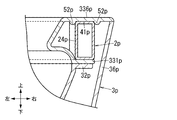
- the rim portion 33 of the present embodiment has a flange piece 331 as shown in FIG. 12B.
- the flange piece 331, the lower inner peripheral part 332, the upper inner peripheral part 333 and the horizontal piece part 336 are integrally formed by resin molding.
- the flange piece 331 is welded to the protruding piece 32 of the bowl portion 31.
- the flange piece 331 extends horizontally.
- the upper surface of the flange piece 331 is positioned below the lower surface of the horizontal piece portion 336 by substantially the same dimension as the vertical length of the support portion 24.
- the flange piece 331 is comprised so that the support part 24 can be pinched
- the support storage part 30 of this embodiment is comprised by the inner peripheral part 330, the horizontal piece part 336, the outer peripheral part 360, and the flange piece 331. As shown in FIG.
- the upper inner peripheral portion 333 includes a first portion 334 located above the side wall on the rear side of the bowl portion 31 and a second portion 335 located above the other side walls. Yes.
- the first part 334 and the second part 335 are formed in an annular shape in plan view, and correspond to the opening periphery of the upper opening 311 of the bowl part 31.
- the first part 334 extends vertically upward from the inner end of the lower inner peripheral part 332 at a position corresponding to the rear side wall of the bowl part 31.
- the second part 335 extends outward from the inner end of the lower inner peripheral part 332, that is, is inclined so as to be located outward as it goes upward.
- the horizontal piece 336 extends from the upper ends of the first part 334 and the second part 335 along the horizontal plane and outward. That is, the horizontal piece 336 is provided over the entire length of the opening periphery of the upper inner peripheral portion 333.
- portions extending in the front-rear direction located on both sides in the left-right direction that is, portions corresponding to the pair of support portions 24 constitute a pair of placement portions 4.
- the rim portion 33 of the present embodiment has a plurality of ribs 337 provided across the horizontal piece portion 336, the upper inner peripheral portion 333, and the lower inner peripheral portion 332 as shown in FIGS. 12A and 12B.
- the plurality of ribs 337 extend along the vertical plane, and are arranged at a constant interval in the direction along the opening periphery of the upper opening 311 of the bowl portion 31 as shown in FIG. 12A.
- the plurality of ribs 337 are provided at positions corresponding to the pair of support portions 24. Therefore, the pair of support portions 24 hits the plurality of ribs 337 in a state where the bowl portion 31 is disposed between the pair of support portions 24 of the support frame 2. Thereby, even if the bowl part 31 is pinched by the support frame 2, it is suppressed that the bowl part 31 is damaged or excessively bent by the reinforcing action of the rib 337.
- the protruding piece 32 of the bowl portion 31 and the flange piece 331 of the rim portion 33 are fixed by welding such as vibration welding.
- the storage space 305 of the present embodiment has a pair of left and right arrangement spaces 300.
- positioning space 300 is a space where a pair of support part 24 is each arrange
- Each of the pair of arrangement spaces 300 is covered with the toilet body 3 on the side (left and right sides away from the toilet body 3), above and on the front, and is open toward the back.
- Each placement space 300 may be partially or entirely covered below (see FIG. 12B), or may not be covered below.
- the support frame 2 includes the reinforcing portion 8
- each of the arrangement spaces 300 is not covered below or provided with the reinforcing portion 8 so as not to interfere with the toilet body 3, thereby reinforcing the toilet body 3. Interference with the part 8 is avoided.
- the support part 24 corresponding to each arrangement space 300 of the support body storage part 30 is disposed, and the load of the toilet body 3 is supported by the support body 20 through the support body storage part 30.
- the toilet body 3 is provided with a pair of placement portions 4.
- the pair of placement portions 4 according to the present embodiment includes portions located on both sides of the horizontal piece portion 336 in the left-right direction.
- Each of the pair of placement portions 4 is configured by the lower surface of the support body storage portion 30 that forms the top surface of the corresponding arrangement space 300.
- the pair of support portions 24 support the pair of placement portions 4, respectively. .
- Each placement unit 4 includes a placement area 41 as shown in FIG. 12B.
- the placement area 41 is an area in which a load from above received by the placement section 4 is applied to each support section 24. That is, each support portion 24 supports the placement portion 4 via the placement region 41, and as a result, each support portion 24 supports the toilet body 3.
- Each mounting region 41 extends in the front-rear direction and is supported by the corresponding support portion 24 over its entire length. As a result, the load applied from the toilet body 3 acts on each support portion 24 as a distributed load across the front-rear direction.
- Each mounting area 41 is composed of a flat lower surface of the corresponding mounting portion 4 and is in planar contact with the upper surface of the corresponding supporting portion 24.
- region 41 may be directly supported by contacting with the corresponding support part 24 like this embodiment, and noise prevention between corresponding support parts 24 is possible. It may be indirectly supported with a material interposed. This will be described in detail later in “(2-3.4) Modifications of other portions”.
- each placement area 41 occupies about 1/3 of the width of each placement section 4. Further, the placement area 41 is formed at a position including the center in the width direction of each placement portion 4 in a cross section orthogonal to the front-rear direction. For this reason, even if it is a case where the load is applied to all the width directions of each mounting part 4, generation
- region 41 is 1/10 or more of the width
- the toilet body 3 is attached to the support frame 2.
- the pair of support portions 24 protruding forward from the fixed body 21 is inserted from the insertion opening 306 into the storage space 305 (see FIG. 14) opened to the rear of the toilet body 3.
- the operator can support the toilet bowl body 3 on the support frame 2 only by moving the toilet bowl body 3 backward so that the support frame 2 is inserted into the storage space 305.
- each arrangement space 300 is covered on the side, upper side, and front side, but is open toward the rear side. For this reason, the support part 24 which protruded toward the front from the fixed body 21 is easily inserted in each arrangement space 300, and thereby the toilet body 3 is supported by the pair of support parts 24.
- the toilet body 3 is integrally formed with the bowl portion 31, the rim portion 33, the trap portion 35, and the skirt portion 36 by welding. For this reason, after the toilet body 3 is supported by the pair of support portions 24, it is not necessary to attach an under cover (skirt) as shown in Patent Document 1 later, and the toilet body 3 is attached to the support frame 2. Installation work becomes easy.
- the toilet body 3 supported by the support frame 2 is fixed to the support frame 2 by fixing means such as fixing by bolts and nuts, fixing by uneven fitting, and the like. This prevents the toilet body 3 from coming off from the support frame 2.
- the fixing means and fixing method of the toilet body 3 to the support frame 2 are not particularly limited.
- the toilet 1 of the present embodiment further includes a movement restriction unit.
- the movement restricting portion is configured to maintain the position of the placement area 41 with respect to each support portion 24, and prevents rattling of the toilet body 3 supported by the support frame 2.
- the movement restricting portion of the present embodiment has a flange piece 331 as a clamping portion provided in the rim portion 33 as shown in FIG.
- the flange piece 331 sandwiches the support portion 24 with the mounting portion 4. Accordingly, the flange piece 331 is configured to maintain the position of the placement portion 4 with respect to each support portion 24 of the toilet body 3.
- Modification Example 2-1 The support frame 2 of the second embodiment is provided with a pair of braces 81 as a pair of reinforcing portions 8.
- the pair of reinforcing portions 8 may have an aspect as shown in FIG. 16. (This is referred to as Modification 2-1.)
- the configuration corresponding to the second embodiment is denoted by the same reference numeral as the configuration of the second embodiment, and “a” is appended to the end of the reference symbol, and redundant description is omitted. .
- Each of the pair of reinforcing portions 8a of the modified example 2-1 includes a lateral reinforcing body 82a and a plurality of vertical reinforcing bodies 83a.
- the horizontal reinforcing body 82a protrudes forward from the lower end of the vertical body 22a.
- the lateral reinforcement body 82a extends in the front-rear direction, and the longitudinal direction of the lateral reinforcement body 82a is parallel to the longitudinal direction of the support portion 24a.
- the horizontal reinforcing body 82a is formed of a square pipe, like the support portion 24a.
- the plurality of vertical reinforcing bodies 83a connect the horizontal reinforcing bodies 82a and the support portions 24a corresponding to the horizontal reinforcing bodies 82a.
- the plurality of vertical reinforcing bodies 83a extend in the up-down direction, and are arranged at regular intervals in the front-rear direction.
- the toilet body 3 is not provided with a configuration corresponding to the flange piece 331, the protruding piece 32, and the like, and the lower part of the storage space 305 is not covered. Does not interfere.
- each reinforcement part 8a of the modification 2-1 is comprised so that the support part 24a may be supported from the downward direction.
- the aspect like this modification may also be sufficient as the reinforcement part 8 in each modification of 1st Embodiment and 1st Embodiment.
- the pair of support portions 24 of the second embodiment are formed in a straight line shape, but may be any shape that matches the shape of the placement portion 4 of the toilet body 3, for example, a curved shape in plan view. May be.
- the pair of support portions 24 of the first embodiment may have a shape that matches the shape of the placement portion 4 of the toilet body 3, and may be formed in a curved shape in plan view, for example.
- each support portion 24 of the second embodiment is configured by hollow square pipes, but may be, for example, a solid square material, and may have a C-shaped section, an I-shaped section, and a T-shaped section. It may be formed in a letter shape, a D-shaped section, an O-shaped section, or an L-shaped section.
- each support portion 24 may be configured to support substantially the entire lower surface of the placement portion 4.
- the horizontal body 23 of the first embodiment and the second embodiment has a pair of reinforcing pieces 233 provided at both ends in the vertical direction of the fixing plate 232 and is formed in a vertical C-shape.
- a reinforcing piece 233 may be provided at either end in the vertical direction of the plate 232 and may be formed in an L-shaped cross section.
- the horizontal body 23 may be comprised by the lip channel steel, for example.
- the horizontal body 23 may be configured by a hollow pipe or square bar.
- the mounting portion 4c of the modified example 2-2-1 is configured by a flange piece 331c of the rim portion 33c.
- the flange piece 331c protrudes outward along the horizontal plane from the lower end portion of the lower inner peripheral portion 332c.
- the placement region 41c is configured by the lower surface of the flange piece 331c.
- the support housing portion 30c of the present modification is configured by the upper end portion of the bowl portion 31c, the flange piece 331c, and the skirt portion 36c that are opposed to the upper end portion of the bowl portion 31c.
- the protruding piece 32 is not provided on the opening periphery of the upper opening 311c of the bowl portion 31c.
- the flange pieces 331c may be provided only at positions corresponding to both the left and right sides of the upper opening 311c of the bowl portion 31c, or may be provided at positions corresponding to both the left and right sides of the upper opening 311c and the front side. May be.
- the placement unit 4 may have a mode as shown in FIG. 17B (this is a modified example 2-2-2).
- this modification the configuration corresponding to the second embodiment is given the same reference numeral as the configuration of the second embodiment, and “d” is added to the end of the reference symbol, and duplicate description is omitted. .
- the mounting portion 4d of the modified example 2-2-2 is configured by a protruding piece 32d provided on the opening periphery of the upper opening 311d of the bowl portion 31d.
- the placement area 41d is configured by the lower surface of the protruding piece 32d.
- the support housing portion 30d of the present modification is composed of an upper end portion of the bowl portion 31d, a protruding piece 32d, and a portion facing the upper end portion of the bowl portion 31d in the skirt portion 36d.
- the protruding pieces 32d may be provided only on both sides in the left-right direction of the upper opening 311d of the bowl portion 31d, or may be provided on both sides in the left-right direction and the front side of the upper opening 311d.
- the mounting unit 4 may have a mode as shown in FIG. 17C (this is a modified example 2-2-3).
- this modification after attaching the same code
- the mounting portion 4e of the modified example 2-2-3 is constituted by a horizontal plate portion 361e protruding from the skirt portion 36e toward the bowl portion 31e.
- the horizontal plate portion 361e is continuous over the entire length of the inner peripheral surface of the skirt portion 36e.
- the horizontal plate portion 361e is provided at a position corresponding to the upper surface of the support portion 24e in the skirt portion 36e.
- the placement area 41e is configured by a part of the lower surface of the horizontal plate portion 361e and is included in the lower surface of the horizontal plate portion 361e.
- the support storage part 30e of this modification is comprised by the upper end part of the bowl part 31e, the horizontal board part 361e, and the part which opposes the upper end part of the bowl part 31e in the skirt part 36e.
- a protruding piece 32e and a flange piece 331e are placed on each horizontal plate portion 361e. That is, the toilet body 3e is supported by the support portion 24e via the horizontal plate portion 361e, the protruding piece 32e, and the flange piece 331e. Note that the protruding piece 32e and the flange piece 331e may not be provided, and the toilet body 3e may be supported only by the horizontal plate portion 361e.
- the mounting unit 4 may have a mode as shown in FIG. 18 (this is referred to as a modified example 2-2-4).
- this modification the configuration corresponding to the second embodiment is given the same reference numeral as the configuration of the second embodiment, and “g” is added to the end of the reference symbol, and redundant description is omitted. .
- the mounting portion 4g of the modified example 2-2-4 is constituted by a support piece 361g protruding from the inner surface of the skirt portion 36g toward the bowl portion 31g.
- the support piece 361g is provided over the entire length of the inner peripheral surface of the lower end portion of the skirt portion 36g.
- the placement region 41g is configured by the lower surface of the support piece 361g.
- the support housing portion 30g of this modification is composed of a lower end portion of a support piece 361g and a skirt portion 36g.
- the support frame 2g of this modification has the same structure as the support frame 2a of modification 2-1.
- the upper end portion of the skirt portion 36g is fixed to the rim portion 33g of the toilet body 3g by welding.
- the support frame 2g can support the toilet main body 3g by supporting the lower end part of the skirt part 36g by the support frame 2g via the mounting part 4g.
- the movement restricting portion of the second embodiment is configured by the flange piece 331 as the sandwiching portion.
- a mode as shown in FIG. 19A may be used (this is a modified example 2-3-1. ).
- this modification about the structure corresponding to 2nd Embodiment, after attaching
- the movement restricting portion of Modification 2-3-1 is configured by a protruding piece 32h protruding outward from the outer surface of the bowl portion 31h along the horizontal plane.
- the protruding piece 32h is continuous over both the left and right sides of the opening edge of the bowl portion 31h and the front side.
- the pair of support portions 24h of the support frame 2h is sandwiched between the horizontal piece portion 336h as the placement portion 4h and the protruding piece 32h. That is, in the present modification, the projecting piece 32h corresponds to the clamping portion.
- the support housing portion 30h according to the present modification includes an inner peripheral portion 330h, a horizontal piece portion 336h, an outer peripheral portion 360h, and a protruding piece 32h.
- the pair of support portions 24h can be sandwiched between the protruding piece 32h and the lateral piece portion 336h (the placement portion 4h) of the toilet body 3h, and thus the support frame 2h
- the movement of the placement region 41h in the front-rear direction, the left-right direction, and the up-down direction can be suppressed.
- rattling of the toilet body 3h with respect to the support frame 2h can be prevented.
- Modification 2-3-2 Further, for example, the movement restricting unit may be configured as shown in FIG. 19B (this is referred to as Modified Example 2-3-2).
- the configuration corresponding to the second embodiment is denoted by the same reference numeral as the configuration of the second embodiment, and “i” is appended to the end of the reference symbol, and redundant description is omitted. .
- the movement restricting portion of Modification 2-3-2 is configured by a horizontal plate portion 361i provided on the skirt portion 36i.
- the horizontal plate portion 361i protrudes from the inner surface of the skirt portion 36i toward the bowl portion 31i side.
- the horizontal plate portion 361i is continuous over the entire length of the inner peripheral surface of the skirt portion 36i.
- the horizontal plate portion 361i is provided at a position corresponding to the lower surface of the support portion 24i in the skirt portion 36i.
- a pair of support part 24i is pinched
- the support storage part 30i of this modification is comprised by the inner peripheral part 330i, the horizontal piece part 336i, the outer peripheral part 360i, and the horizontal board part 361i.
- the pair of support portions 24i can be sandwiched between the horizontal piece portion 336i (mounting portion 4i) and the horizontal plate portion 361i in the toilet body 3i, and thus the support portion 24i.
- the movement of the placement area 41i in the front-rear direction, the left-right direction, and the up-down direction can be suppressed. Thereby, shakiness of the toilet body 3i with respect to the support frame 2i can be prevented.
- Modification 2-4-1 The movement restricting portion of the second embodiment holds the position of the placement region 41 with respect to each support portion 24 by sandwiching the pair of support portions 24 between the placement portion 4 and the sandwiching portion. 20 may be employed (this is referred to as Modification 2-4-1).
- Modification 2-4-1 the configuration corresponding to the second embodiment is given the same reference numeral as the configuration of the second embodiment, and “p” is added to the end of the reference symbol, and the duplicate description is omitted. .
- the movement restricting portion of the modified example 2-4-1 is configured by a protrusion 52p.
- the projecting portion 52p of the present modification projects along the outer edge of the support portion 24p on the lower surface of the horizontal piece portion 336p.
- the protrusions 52p are positioned on both sides in the left-right direction of each support 24p as shown in FIG. Thereby, the relative movement of the placement area 41p with respect to the support portion 24p is restricted at least in the left-right direction, and the position of the placement area 41p with respect to the support portion 24p is maintained.
- Modification 2-4-2 The protrusions 52p of the modified example 2-4-2 are provided on the left and right sides of the respective support portions 24p. However, for example, an embodiment as shown in FIG. 4-2).
- this modification about the structure corresponding to 2nd Embodiment, after attaching
- the protrusion 52q of the present modification is provided along the outer edge located on the outer side of the outer edges on the left and right sides of each support 24q. Similar to the modified example 2-4-1, the protrusions 52q may be provided only at locations corresponding to the pair of support portions 24q. Further, the protrusion 52q may be constituted by a ridge or may be constituted by a plurality of dot-like protrusions.
- the placement region 41q is configured by a part of the lower surface of the horizontal piece 336q. The support portion 24q is inserted into a space surrounded by the horizontal piece portion 336q, the skirt portion 36q, and the horizontal piece (flange piece 331q).
- the protrusion 52q is positioned along the outer edge of each support 24q. Thereby, the relative movement of the placement region 41q with respect to the support portion 24q in at least the left-right direction is restricted, and the position of the placement region 41q with respect to the support portion 24q is maintained.
- the movement restricting unit may have a form as shown in FIG. 22 (this is a modified example 2-5-1).
- the configuration corresponding to the second embodiment is denoted by the same reference numeral as the configuration of the second embodiment, and “u” is appended to the end of the reference symbol, and redundant description is omitted. .
- the movement restricting portion of Modification 2-5-1 has a locking portion 54u and a locked portion 55u.
- the locking part 54u is provided in the horizontal piece part 336u as the mounting part 4u.
- the locking part 54u is disposed in a portion corresponding to the placement area 41u, that is, the locking part 54u is provided in the placement area 41u.
- the locking portion 54u protrudes downward from a portion in the placement region 41u of the horizontal piece portion 336u.
- the locking part 54u has a shaft-like part 541u having a first diameter and a huge part 542u having a second diameter larger than the first diameter.
- the locked portion 55u is provided in each support portion 24u.
- the locked portion 55u is formed by a so-called daruma hole.
- the first hole 551u and the second hole 552u are arranged along the longitudinal direction of the support portion 24u, and the first hole 551u and the second hole 552u are connected to each other.
- the first hole 551u is formed larger than the diameter (second diameter) of the enormous portion 542u.
- the second hole 552u is formed smaller than the second diameter and larger than the first diameter.
- the hooking portion 54u is hooked on the hooked portion 55u as follows.
- the locking portion 54u is inserted into the first hole 551u, and the horizontal piece portion 336u is placed on the support portion 24u. In this state, when the horizontal piece 336u is moved toward the second hole 552u side (forward), the locking portion 54u and the locked portion 55u are engaged with each other.
- first hole 551u and the second hole 552u are aligned in the front-rear direction, and may be aligned in the left-right direction.
- Modification 2-5-2 The movement restricting portion of the modified example 2-5-1 is configured by the locking portion 54u and the locked portion 55u, but the locking portion 54u and the locked portion 55u are, for example, in the form shown in FIG. It may be present (this is a modified example 2-5-2).
- the configuration corresponding to the second embodiment is denoted by the same reference numeral as the configuration of the second embodiment, and “v” is appended to the end of the reference symbol, and redundant description is omitted. .
- the locking part 54v of this modification is configured by an L-shaped locking claw 540v.
- the front end of the locking claw 540v extends forward.
- the locked portion 55v is configured by a rectangular through hole 550v.
- a locking claw 540v can be inserted into the through hole 550v.
- the hooking portion 54v is hooked on the hooked portion 55v as follows.
- the locking claw 540v is inserted into the through hole 550v, and the horizontal piece portion 336v is placed on the support portion 24v.
- the locking claw 540v and the through hole 550v are engaged with each other.
- the relative movement of the placement area 41v in the left-right direction with respect to the support portion 24v is restricted, and the position of the placement area 41v with respect to the support portion 24v is maintained.
- claw 540v of this modification extended toward the front, you may extend toward either back or the left-right direction, for example.
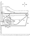
- the trap unit 35 of the second embodiment is a so-called S-shaped trap, but an electric trap device may be used as shown in FIG. 24, for example.
- the configuration corresponding to the second embodiment is denoted by the same reference numeral as the configuration of the second embodiment, and “y” is added to the end of the reference symbol, and redundant description is omitted. .
- the trap part 35y of Modification 2-6 includes a trap cylinder 351y whose downstream end (rear end) is movable in the vertical direction, a drive part 352y that drives the trap cylinder 351y, and a case 353y that houses the trap cylinder 351y.
- the trap cylinder 351y is configured such that sealed water can be formed when the downstream end faces upward, and drainage can be performed when the downstream end faces downward.
- the drive source of the drive unit 352y is, for example, a motor.
- the lower end of the trap part 35y is located above the lower end of the skirt part 36y. Thereby, the trap part 35y of this modification is accommodated in the skirt part 36y.
- the electric trap portion is heavier than the S-shaped trap as in the present embodiment, but is firmly fixed to the vertical surface 70 by the support frame 2y, and thus supports the toilet body 3y without rattling. can do.
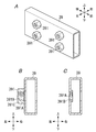
- Modification 2-7-1 In the second embodiment, the support portion 24 directly supports the toilet body 3, but for example, as shown in FIG. 25A, a rail 39 is provided on the toilet body 3, and this rail 39 is supported by the support portion 24. (This is referred to as Modification 2-7-1).
- the rail 39 is configured by a hollow square pipe as shown in FIG. 25B.
- the rail 39 is provided in the support storage part 30 of the toilet body 3, and the internal space becomes a storage space 305 into which the support part 24 is inserted when the toilet 39 is incorporated in the toilet body 3.
- the rail 39 may be formed in a C-shaped section, an I-shaped section, a T-shaped section, a D-shaped section, an O-shaped section, or an L-shaped section.
- the rail 39 is provided with a fixing portion 391 to which the support portion 24 is fixed at the rear end portion.
- the fixing portion 391 is provided with a through hole 391A penetrating in the left-right direction at the rear end portion of the rail 39, and a nut 391C is provided so that an internal female screw 391B can communicate with the through hole 391A. It is provided and configured.
- the female screw 391B is formed by the nut 391C.
- the female screw 391B may be directly formed on the inner surface of the through hole 391A.
- the support portion 24 is provided with a through hole at a position corresponding to the fixed portion 391 in a state where the rail 39 is coupled.
- the fixing portion 391 of the rail 39 is provided with the female screw 391B, and the support portion 24 is provided with the through hole.
- the rail 39 is provided with the through hole, and the support portion 24 is provided with the female screw. May be.
- the support frame 2 is not provided with the reinforcing portion 8 such as the brace 81 and does not interfere with the rail 39.
- the support frame 2 may be provided with a reinforcing portion 8 such as a brace 81.
- the rail 39 is notched or the reinforcing portion 8 is provided at a position that does not interfere with the rail 39.
- the frame 2 and the rail 39 are configured not to interfere with each other.
- the toilet body 3 includes a bowl portion 31 and a trap portion 35, and a trap portion 35, and a rim portion 33 formed by injection molding. The portion having the portion 35 and the rim portion 33 are fixed.
- the rail 39 is inserted.
- the skirt portion 36 is fixed to the rim portion 33 by welding.
- the toilet bowl main body 3 is comprised.
- the toilet body 3 has a storage space 305 inside the rail 39.
- the support 20 is inserted into the storage space 305, and the load of the toilet body 3 is supported by the support 20 through the rail 39.
- the width w3 of the support portion 24 shown in FIG. 11B is formed to be equal to or smaller than the width w4 of the internal space (storage space 305) of the rail 39 shown in FIG. 25B.
- the vertical length (height) h3 of the support portion 24 shown in FIG. 11B is formed to be equal to or smaller than the vertical length (height) h4 of the internal space of the rail 39 shown in FIG. 25B.
- a bolt is inserted from the through hole of the support portion 24, and this bolt is screwed into the female screw 391B of the rail 39, so that the support portion 24 and the rail 39 are fixed.
- the rail 39 incorporated in the toilet body 3 is easily fixed to the support frame 2, and the toilet body 3 can be easily attached to the support frame 2.
- Modification 2-7-2 The movement restricting portion of the second embodiment holds the position of the placement region 41 with respect to each support portion 24 by sandwiching the pair of support portions 24 between the placement portion 4 and the sandwiching portion.
- the rail 39 may be sandwiched as shown in 28A (this is referred to as Modified Example 2-7-2).
- the configuration corresponding to the second embodiment is denoted by the same reference numeral as the configuration of the second embodiment, and “j” is appended to the end of the reference symbol, and redundant description is omitted. .
- the movement restricting portion of Modification 2-7-2 is composed of a fixed body 56j that fixes the placement region 41j and each rail 39j to each other.
- the fixed body 56j of this modification is configured by a screw tool.
- the rail 39j is inserted into a space surrounded by the horizontal piece portion 336j, the skirt portion 36j, and the horizontal piece (flange piece 331j).
- a screw seat 51j that protrudes downward is provided on the lateral piece 336j of the rim portion 33j.
- the screw seat 51j is provided with a plurality of female screws, and the plurality of female screws are arranged at predetermined intervals along the length direction of the rail 39j.
- the placement area 41j of this modification is configured by the lower surface of the screw seat 51j.
- Modification 2-7-3 The fixing body 56j of Modification 2-7-2 fixes the horizontal piece 336j and the rail 39j to each other.
- the fixing body 56j may have a form as shown in FIG. Example 2-7-3).
- the configuration corresponding to the second embodiment is given the same reference numeral as the configuration of the second embodiment, and “k” is added to the end of the reference symbol, and duplicate description is omitted. .
- the rim portion 33k of the modified example 2-7-3 has a flange piece 331k.
- the support housing portion 30k according to this modification is configured with a top portion of the bowl portion 31k, a flange piece 331k, and a portion facing the top end portion of the bowl portion 31k in the skirt portion 36k.
- a plurality of female screws are formed on the flange piece 331k.
- the plurality of female screws are formed at a predetermined pitch along the length of the rail 39k in the flange piece 331k.
- the placement area 41k is constituted by the lower surface of the flange piece 331k.
- the screw tool 56k is passed from below the rail 39k, and the rail 39k is screwed to the female screw of the flange piece 331k.
- the movement of the mounting area 41k with respect to the rail 39k in the front-rear direction, the left-right direction, and the vertical direction is suppressed, and the position of the mounting area 41k with respect to the rail 39k is maintained. Therefore, according to this modification, it is possible to prevent the toilet body 3k from rattling with respect to the support frame 2k.
- the fixed body 56 may have, for example, a mode as shown in FIG. 28C (this is referred to as Modification 2-7-4).
- the configuration corresponding to the second embodiment is given the same reference numeral as the configuration of the second embodiment, and “L” is added to the end of the reference symbol, and the duplicate description is omitted. .
- the rim portion 33L of this modification has a flange piece 331L. Moreover, the bowl part 31L has the protrusion piece 32L provided in the opening periphery of the upper opening part 311L.
- the support housing portion 30L of the present modification is configured by an upper end portion of the bowl portion 31L, a protruding piece 32L, and a portion of the skirt portion 36L that faces the upper end portion of the bowl portion 31L.
- the flange piece 331L and the protruding piece 32L are formed with a plurality of internal threads that penetrate the flange piece 331L and the protruding piece 32L.
- the plurality of female screws are arranged at a predetermined pitch along the length direction of the rail 39L in the flange piece 331L and the protruding piece 32L.
- the placement area 41 ⁇ / b> L is configured by the lower surface of the protruding piece 32.
- a screw tool is passed from below the rail 39L, and the rail 39L is screwed to a plurality of female threads of the protruding piece 32L and the flange piece 331L.
- the movement of the mounting area 41L with respect to the rail 39L in the front-rear direction, the left-right direction, and the vertical direction can be suppressed, and the position of the mounting area 41L with respect to the rail 39L is maintained. Therefore, according to this modified example, rattling of the toilet body 3L with respect to the support frame 2L can be prevented.
- a female screw may be formed on one of the flange piece 331L and the protruding piece 32L, and on the other hand, a flaw hole may be formed on the same axis as the female screw.
- Modification 2-7-5 Further, the fixed body 56 may have a mode as shown in FIG. 28D, for example (this is referred to as Modification 2-7-5).
- this modification about the structure corresponding to 2nd Embodiment, after attaching
- the support 361m that protrudes from the inner surface of the skirt portion 36m toward the bowl portion 31m is provided on the skirt portion 36m of the modification.
- the support storage part 30m of this modification is comprised by the upper end part of the bowl part 31m, the support piece 361m, and the part which opposes the upper end part of the bowl part 31m in the skirt part 36m.
- the support piece 361m is provided at a position corresponding to the upper surface of the rail 39m in the skirt portion 36m.
- the support piece 361m is continuous over the entire length of the inner peripheral surface of the skirt portion 36m.
- the placement portion 4m is configured by a support piece 361m, and the placement region 41m is included in the lower surface of the support piece 361m.
- a plurality of internal threads are formed on the support piece 361m.
- the plurality of female screws are arranged at a predetermined pitch along the length direction of the rail 39m in the support piece 361m.
- Modification 2-7-6 Further, the fixed body 56 may have a form as shown in FIG. 29A, for example (this is referred to as Modification 2-7-6).
- the configuration corresponding to the second embodiment is denoted by the same reference numeral as the configuration of the second embodiment, and “n” is appended to the end of the reference symbol, and redundant description is omitted. .
- the fixed body 56n of Modification 2-7-6 is constituted by a tapping screw.
- the lateral piece 336n of the rim portion 33n is provided with a screwing portion 51n protruding downward.
- the screwing portion 51n has a predetermined thickness.
- the placement area 41n of the present modification is configured by the lower surface of the screwing portion 51n.
- a tapping screw (fixed body 56n) is passed from below the rail 39n, screwed into the screwing portion 51n, and screwed.
- the rail 39n is inserted into a space surrounded by the horizontal piece portion 336n, the skirt portion 36n, and the horizontal piece (flange piece 331n).
- Modification 2-7-7 Further, the fixed body 56 may have, for example, a mode as shown in FIG. 29B (this is referred to as Modification 2-7-7).
- the configuration corresponding to the second embodiment is denoted by the same reference numeral as the configuration of the second embodiment, and “o” is appended to the end of the reference symbol, and redundant description is omitted. .
- the fixed body 56o of the modified example 2-7-7 is composed of a bolt and a nut.
- the flange piece 331o of the rim portion 33o is provided with a hole penetrating in the vertical direction.
- the rail 39o is provided with a through hole penetrating in the vertical direction, and the through hole is provided at a position corresponding to the hole of the flange piece 331o.
- the placement region 41o of this modification is configured by the lower surface of the flange piece 331o.
- the support housing portion 30o of the present modification is configured by a portion facing the upper end portion of the bowl portion 31o in the upper end portion of the bowl portion 31o, the flange piece 331o, and the skirt portion 36o.
- the bolt is passed through the hole of the rail 39o and the through hole of the flange piece 331o from the lower side of the rail 39o, and a nut is screwed to the tip of the bolt and fastened.
- each rail 39 and the placement area 41 are in direct contact.
- an anti-noise material is provided between each rail 39 and the placement area 41.
- the configuration corresponding to the second embodiment is denoted by the same reference numeral as the configuration of the second embodiment, and “w” is added to the end of the reference symbol, and redundant description is omitted. .
- the noise preventing material 9w of the modified example 2-7-8 is provided between the rail 39w and the mounting area 41w and between the rail 39w and the flange piece 331w.
- the rail 39w is inserted into a space surrounded by the horizontal piece portion 336w, the skirt portion 36w, and the horizontal piece (flange piece 331w).
- a low friction tape made of rubber, Teflon (registered trademark), synthetic resin, or the like is used.
- the noise preventing material 9w is provided between the rail 39w and the mounting area 41w and between the rail 39w and the flange piece 331w.
- the configuration corresponding to the second embodiment is given the same reference numeral as the configuration of the second embodiment, and “x” is added to the end of the reference symbol, and redundant description is omitted. .
- the noise preventing material 9x of Modification 2-7-9 is provided only between the rail 39x and the placement area 41x.
- the rail 39x is inserted into a space surrounded by the horizontal piece portion 336x, the skirt portion 36x, and the horizontal piece (flange piece 331x).
- the mounting portion 4 may have a form as shown in FIG. 31 (this is referred to as Modified Example 2-7-10).
- this modification about the structure corresponding to 2nd Embodiment, after attaching
- the mounting portion 4g1 of Modification 2-7-10 is configured by a support piece 361g1 protruding from the inner surface of the skirt portion 36g1 to the bowl portion 31g1 side.
- the support piece 361g1 is provided over the entire length of the inner peripheral surface of the lower end portion of the skirt portion 36g1.
- the placement area 41g1 is configured by the lower surface of the support piece 361g1.
- the support housing portion 30g1 of the present modification is configured with a support piece 361g1, a lower end portion of the skirt portion 36g1, and a portion facing the lower end portion of the skirt portion 36g1 in the bowl portion 31g1.
- the upper end portion of the skirt portion 36g1 is fixed to the rim portion 33g1 of the toilet body 3g1 by welding. For this reason, the support frame 2g1 can support the toilet body 3g1 by supporting the lower end portion of the skirt portion 36g1 by the support frame 2g1 inserted into the rail 39g1 via the placement portion 4g1.
- the bowl portion 31 and the rim portion 33 of the first embodiment, the second embodiment, and each modification described above may be joined by bonding using an adhesive instead of welding.
- the rim portion 33 and the skirt portion 36 of the first embodiment, the second embodiment, and each modification described above may be joined by bonding using an adhesive.
- the toilet body 3 of 1st Embodiment, 2nd Embodiment, and each modification mentioned above is a product made from a synthetic resin, it may be made from metal (for example, a thin metal plate) or earthenware.
- the material of 3 is not limited.
- the fixing part 200 of the support frame 2 in the first embodiment and the modified examples of the first embodiment described above is fixed to the fixed part 37 of the toilet body 3 with the fixing tool 74, the fixing tool 74. May be omitted.
- the fixed portion 37 is disposed along the rear surface of the fixing portion 200, thereby restricting the toilet body 3 from moving forward relative to the support frame 2.
- the support body 20 of each modification of 1st Embodiment and 1st Embodiment mentioned above is comprised by the hollow square pipe, it may be a solid square material, for example, and cross section It may be formed in a C shape, a cross section I shape, a cross section T shape, a cross section D shape, a cross section O shape, or a cross section L shape.
- the mounting area 41 of the second embodiment and each modification of the second embodiment described above is in contact with the entire upper surface of each support portion 24 in the cross section along the left-right direction. It is also possible to adopt a mode in which only a part of the upper surface is contacted. For example, an aspect is provided in which a part projecting downward to form the placement region 41 is provided in a part of the horizontal piece part 336 and the lower surface of the projecting part is placed on a part of the upper surface of the support part 24 in cross section Is mentioned.
- each placement portion 4 is connected to each support portion 24 via at least one placement region 41 extending in the front-rear direction.
- the number of placement areas 41 is not limited.
- each placement unit 4 may be supported by one support unit 24 via a plurality of placement regions 41.
- the vertical surface 70 of 1st Embodiment, 2nd Embodiment, and each modification mentioned above is comprised by the wall surface of the toilet room, vertical surfaces other than the wall surface in a structural material may be sufficient.
- the vertical surface 70 may be comprised by the front surface of box bodies, such as a cabinet, for example.
- the frame 2 when the support frame 2 is attached to a wall panel, the frame is arranged on the back side of the wall panel, The support frame 2 may be attached to the wall panel by connecting to the support frame 2. Thereby, it can attach firmly with respect to the vertical surface 70 (front surface of a wall panel) so that the fixed body 21 may not move.
- the support frame 2 when the rigidity of the wall is high, the support frame 2 may be directly attached to the wall.
- the toilet bowl 1 of 1st Embodiment, 2nd Embodiment, and each modification mentioned above was a so-called western-style toilet bowl which a user can seat on the toilet seat 61
- the toilet bowl for male piss It may be.
- the toilet bowl is configured such that the support frame is fixed to the vertical surface and the toilet body is supported by the support frame.
- the attachment structure of the toilet becomes a structure that is strong against external force when the user puts a hand on the toilet.
- the support 20 is stored in the support. It may be performed by being inserted into the portion 30 and thereafter being fixed to the fixing portion 200 by the fixing tool 74.
- first embodiment, the second embodiment, and each modification can be appropriately changed according to the environment and specifications of the installation site.
- the toilet bowl 1 of 1st Embodiment, 2nd Embodiment, and each modification has the following characteristics.
- the toilet 1 includes a toilet main body 3 in which a bowl portion 31 is formed, and a support frame 2 that can be fixed to a vertical surface 70.
- the toilet body 3 includes a support body storage unit 30 in which a storage space 305 is formed.
- the support frame 2 includes a support 20 that is disposed in the storage space 305 and supports the support storage unit 30.
- An insertion opening 306 for inserting the support 20 into the storage space 305 is formed in the support storage 30.
- this toilet 1 is called the toilet 1 of a 1st aspect.
- the support body 20 of the support frame 2 is disposed in the storage space 305 and stored in the support body storage section 30.
- the support 20 (the part that supports the toilet body 3 in the support frame 2) is difficult to see on the appearance, and the toilet 1 has a good appearance.
- the support body 20 can be easily inserted into the support body storage part 30 through the insertion opening 306, and the toilet 1 can be manufactured easily.
- the toilet body 3 includes a bowl portion 31 that opens upward, a skirt portion 36 that is formed in a U shape in plan view and covers the outside of the bowl portion 31, an upper end portion of the bowl portion 31, and an upper end portion of the skirt portion 36. And a rim portion 33 connected to each other.
- the upper end portion of the skirt portion 36 is connected to the rim portion 33 by welding or adhesion.
- the storage space 305 is located in a region 101 surrounded by the bowl portion 31, the skirt portion 36 and the rim portion 33.
- this toilet 1 is called the toilet 1 of a 2nd aspect.
- the support body 20 can be arranged in the region 101 surrounded by the bowl part 31, the skirt part 36, and the rim part 33.
- the toilet 1 of the first embodiment and each modified example of the first embodiment has the following additional features in the toilet 1 of the second aspect.
- An insertion opening 306 is formed in the lower surface of the support housing portion 30.
- a storage space 305 is opened downward through an insertion opening 306.
- this toilet 1 is called the toilet 1 of a 3rd aspect.
- the support 20 can be easily inserted into the support storage 30 from below through the insertion opening 306.
- the toilet 1 of the first embodiment, the second embodiment, and each modified example has the following additional features in the toilet 1 of the first to third aspects.
- a support housing part 30 is provided at the upper end of the bowl part 31.
- this toilet 1 is called the toilet 1 of the 4th aspect.
- the support body 20 can support a portion of the toilet body 3 where a user's load is easily applied.
- the toilet bowl 7-9 has the following additional features in the toilet bowl 1 of the fourth aspect.
- the support storage part 30 includes an inner peripheral part 330 extending upward from the upper end part of the bowl part 31, a horizontal piece part 336 extending outward from the upper end part of the inner peripheral part 330, and a horizontal piece part And an outer peripheral portion 360 extending downward from the outer end portion of 336 and facing the inner peripheral portion 330.
- the horizontal piece 336 is supported by the support 20 from below.
- this toilet 1 is called the toilet 1 of a 5th aspect.
- the support body 20 can be covered by the inner peripheral portion 330, the lateral piece portion 336, and the outer peripheral portion 360.
- the toilet bowl 1 of each modification of 2nd Embodiment and 2nd Embodiment has the additional characteristic shown below in the toilet bowl 1 of a 1st or 2nd aspect.
- An insertion opening 306 is formed on the rear surface of the support housing portion 30.
- a storage space 305 is opened rearward through an insertion opening 306.
- this toilet 1 is called the toilet 1 of a 6th aspect.
- the operator supports the toilet bowl body 3 simply by moving the toilet bowl body 3 rearward so that the support frame 2 is inserted into the storage space 305 opened rearward. It can be supported by the frame 2. For this reason, the operation of attaching the toilet body 3 to the support frame 2 is facilitated.
- the toilet bowl 1 of the modified example 2-7-1 of the second embodiment has the following additional features in the toilet bowl 1 of the sixth aspect.
- the support frame 2 includes a fixed body 21 that can be fixed to the vertical surface 70 with the rear surface along the vertical surface 70.
- the support body 20 has a pair of support portions 24 that protrude forward from the fixed body 21 and are separated in the left-right direction.
- the pair of support portions 24 are disposed in the storage space 305, and the support body storage portion 30 is supported by the pair of support portions 24.
- the support housing part 30 has a pair of rails 39 that are separated in the left-right direction and correspond to the pair of support parts 24 on a one-to-one basis.
- a corresponding support portion 24 of the pair of support portions 24 is disposed inside each of the pair of rails 39.
- the pair of support portions 24 can slide in the front-rear direction with respect to the corresponding rail 39 of the pair of rails 39.
- this toilet 1 is called the toilet 1 of the 7th aspect.
- the toilet body 3 can be supported by the support frame 2 by inserting the pair of support portions 24 into each of the pair of rails 39.
- the toilet bowl 1 includes a rail 39 whose inner space is a storage space 305 in the support body storage unit 30.
- the width w3 of the support part 24 is substantially the same or smaller than the width w4 of the internal space of the rail 39, and the vertical length h3 of the support part 24 is substantially the same or smaller than the vertical length h4 of the internal space of the rail 39. For this reason, when the support portion 24 is inserted into the rail 39, rattling is unlikely to occur.
- the toilet bowl 1 of the modified example 2-7-1 of the second embodiment has the following additional features in the toilet bowl 1 of the seventh aspect.
- One of the rail 39 and the support portion 24 has a female screw, and the other has a through hole. A bolt inserted through the through hole is fastened to the female screw.
- this toilet 1 is called the toilet 1 of an 8th aspect.
- the rail 39 is easily fixed to the support portion 24.
- the toilet 1 of the first embodiment, the second embodiment, and each modified example has the following additional features in the toilet 1 of any one of the first to sixth aspects.
- the support frame 2 includes a fixed body 21 that can be fixed to the vertical surface 70 with the rear surface along the vertical surface 70.
- the support body 20 has a pair of support portions 24 that protrude forward from the fixed body 21 and are separated in the left-right direction. A pair of support portions 24 are disposed in the storage space 305.
- the support storage part 30 is supported by the pair of support parts 24.
- this toilet 1 is called the toilet 1 of a 9th aspect.
- the support housing portion 30 is supported by the pair of support portions 24 protruding forward from the fixed body 21.
- the toilet 1 of the first embodiment, the second embodiment and the modified examples 1-1 to 2-7-7 and 2-7-10 is the same as the toilet 1 of any of the first to sixth aspects. It has the following additional features.
- the upper surfaces of the pair of support portions 24 are flat. With the upper surfaces of the pair of support portions 24 in contact with the support body storage portion 30, the support body storage portion 30 is supported from below by the pair of support portions 24.
- this toilet 1 is called the toilet 1 of a 10th aspect.
- the support 24 and the toilet body 3 are easily brought into surface contact.
- the toilet 1 of the first embodiment, the second embodiment and the modified examples 1-1 to 2-6 and 2-7-2 to 2-7-10 is the toilet 1 of the ninth or tenth aspect. It has the following additional features.
- the support frame 2 includes a pair of reinforcing portions 8 that are separated in the left-right direction and correspond to the pair of support portions 24 on a one-to-one basis.
- the pair of support portions 24 are connected to the fixed body 21 via the pair of reinforcement portions 8.
- this toilet 1 is called the toilet 1 of an 11th aspect.
- the support frame 2 includes a pair of reinforcing portions 8 that reinforce the pair of support portions 24 in a one-to-one correspondence.
- Each of the pair of reinforcing portions 8 is formed across the corresponding support portion 24 and the fixed body 21 of the pair of support portions 24.
- the strength and rigidity of the support frame 2 are improved, and the toilet 1 is deformed by a load applied from the toilet body 3 to the support 24 and a reaction force applied from the support 24 to the toilet body 3. To prevent or break.
- the toilet 1 of the first embodiment, the second embodiment, and the modified examples 1-1 to 2-6 and 2-7-2 to 2-7-10 is the following in the toilet 1 of the eleventh aspect. It has additional features.
- Each of the pair of reinforcing portions 8 is located below the corresponding support portion 24 of the pair of support portions 24.
- Each of the pair of support portions 24 is connected to the fixed body 21 via a corresponding reinforcement portion 8 of the pair of reinforcement portions 8.
- this toilet 1 is referred to as the toilet 1 of the twelfth aspect.
- the support frame 2 is reinforced by the pair of reinforcement portions 8 positioned below the pair of support portions 24.
- each of the pair of reinforcing portions 8 is a brace connecting the corresponding support portion 24 and the fixed body 21.
- the reinforcing portion 8 can be realized with a simple structure of bracing.
- the fixed body 21 has a fixed plate 232 whose rear surface is fixed along the vertical surface 70.
- the fixing plate 232 is provided with a fixing tool insertion hole 231 through which the fixing tool 73 fixed to the vertical surface 70 is passed.
- this toilet bowl 1 is called the toilet bowl 1 of the 13th aspect.
- the support frame 2 can be easily fixed to the vertical surface 70 by a fixing tool 73 such as a screw tool.
- the manufacturing method of the toilet 1 of the first embodiment, the second embodiment, and each modified example has the following characteristics.
- the toilet 1 includes a toilet main body 3 in which a bowl portion 31 is formed, and a support frame 2 that can be fixed to a vertical surface 70.
- the toilet body 3 includes a support body storage unit 30 in which a storage space 305 is formed.
- the support frame 2 includes a support 20 that is disposed in the storage space 305 and supports the support storage unit 30.
- An insertion opening 306 is formed in the support housing portion 30.
- the support 20 is inserted into the storage space 305 from the insertion opening 306.
- the method for manufacturing the toilet 1 is referred to as the method for manufacturing the toilet 1 according to the first aspect.
- the support 20 is stored in the support storage unit 30, and the support 20 is difficult to see in appearance and can be manufactured with good appearance.
- the support body 20 can be simply arrange
- a support housing part 30 is provided at the upper end of the bowl part 31.
- An insertion opening 306 is formed in the lower surface of the support housing portion 30. The support 20 is inserted into the storage space 305 through the insertion opening 306 from below the support storage 30.
- this method for manufacturing the toilet 1 is referred to as a method for manufacturing the toilet 1 of the second aspect.
- the support body 20 can be simply attached to the support body storage section 30 simply by inserting the support body 20 from below into the support body storage section 30 through the insertion opening 306.
- the toilet 1 can be easily manufactured.
Landscapes
- Health & Medical Sciences (AREA)
- Life Sciences & Earth Sciences (AREA)
- Engineering & Computer Science (AREA)
- Hydrology & Water Resources (AREA)
- Public Health (AREA)
- Water Supply & Treatment (AREA)
- Sanitary Device For Flush Toilet (AREA)
- Floor Finish (AREA)
Abstract
L'invention concerne des toilettes qui ont une bonne aptitude au façonnage et dans lesquelles les éléments du cadre de support supportant les toilettes ne sont pas facilement visibles, et un procédé de fabrication de toilettes. Ces toilettes (1) comportent un corps principal de toilettes (3) dans lequel une cuvette (31) est formée, et un cadre de support (2) qui peut être fixé sur une paroi verticale (70). Le corps principal de toilettes (3) comprend une unité de logement de corps de support (30) dans laquelle un espace de logement est formé. Le cadre de support (2) comporte un corps de support (20) qui est logé dans l'espace de logement et qui supporte l'unité de logement de corps de support (30). Dans l'unité de logement de corps de support (30), une ouverture d'insertion (306) est formée pour insérer le corps de support (20) dans l'espace de logement.
Priority Applications (2)
| Application Number | Priority Date | Filing Date | Title |
|---|---|---|---|
| CN201780012058.XA CN108699827B (zh) | 2016-02-19 | 2017-01-20 | 马桶以及马桶制造方法 |
| EP17752887.4A EP3418458A4 (fr) | 2016-02-19 | 2017-01-20 | Toilettes, et procédé de fabrication de toilettes |
Applications Claiming Priority (4)
| Application Number | Priority Date | Filing Date | Title |
|---|---|---|---|
| JP2016-030470 | 2016-02-19 | ||
| JP2016030470A JP6611047B2 (ja) | 2016-02-19 | 2016-02-19 | 便器、および便器の製造方法 |
| JP2016045015A JP6765068B2 (ja) | 2016-03-08 | 2016-03-08 | 便器 |
| JP2016-045015 | 2016-03-08 |
Publications (1)
| Publication Number | Publication Date |
|---|---|
| WO2017141623A1 true WO2017141623A1 (fr) | 2017-08-24 |
Family
ID=59625807
Family Applications (1)
| Application Number | Title | Priority Date | Filing Date |
|---|---|---|---|
| PCT/JP2017/001965 WO2017141623A1 (fr) | 2016-02-19 | 2017-01-20 | Toilettes, et procédé de fabrication de toilettes |
Country Status (3)
| Country | Link |
|---|---|
| EP (1) | EP3418458A4 (fr) |
| CN (1) | CN108699827B (fr) |
| WO (1) | WO2017141623A1 (fr) |
Families Citing this family (2)
| Publication number | Priority date | Publication date | Assignee | Title |
|---|---|---|---|---|
| CZ309136B6 (cs) * | 2020-06-24 | 2022-02-23 | DOMKAT, s.r.o. | Odpadní systém výškově stavitelné toalety |
| CN116180858A (zh) * | 2021-11-29 | 2023-05-30 | 赵丕君 | 壁挂式亚克力马桶 |
Citations (2)
| Publication number | Priority date | Publication date | Assignee | Title |
|---|---|---|---|---|
| JPH10273927A (ja) * | 1997-02-03 | 1998-10-13 | Inax Corp | 壁掛け便器の設置構造 |
| JP2014173390A (ja) * | 2013-03-12 | 2014-09-22 | Panasonic Corp | 便器設置構造 |
Family Cites Families (6)
| Publication number | Priority date | Publication date | Assignee | Title |
|---|---|---|---|---|
| AU414129B1 (en) * | 1966-07-18 | 1971-06-15 | Doulton Potteries (Australia) Pty. Limited | Improvements in means for securing water closet pans in position |
| AU613502B2 (en) * | 1988-07-28 | 1991-08-01 | Caroma Industries Limited | Sanitary ware fixing |
| DE19710647A1 (de) * | 1997-03-14 | 1998-09-17 | Villeroy & Boch | Waschbeckeninstallation |
| DE202007016854U1 (de) * | 2007-11-30 | 2008-02-21 | Villeroy & Boch Ag | Spülwassereinrichtung für ein Toilettenbecken |
| JP2010106621A (ja) * | 2008-10-31 | 2010-05-13 | Toto Ltd | 昇降便器 |
| CN203213258U (zh) * | 2013-05-03 | 2013-09-25 | 王晓风 | 一种可折叠嵌入式马桶 |
-
2017
- 2017-01-20 CN CN201780012058.XA patent/CN108699827B/zh active Active
- 2017-01-20 WO PCT/JP2017/001965 patent/WO2017141623A1/fr active Application Filing
- 2017-01-20 EP EP17752887.4A patent/EP3418458A4/fr active Pending
Patent Citations (2)
| Publication number | Priority date | Publication date | Assignee | Title |
|---|---|---|---|---|
| JPH10273927A (ja) * | 1997-02-03 | 1998-10-13 | Inax Corp | 壁掛け便器の設置構造 |
| JP2014173390A (ja) * | 2013-03-12 | 2014-09-22 | Panasonic Corp | 便器設置構造 |
Non-Patent Citations (1)
| Title |
|---|
| See also references of EP3418458A4 * |
Also Published As
| Publication number | Publication date |
|---|---|
| EP3418458A4 (fr) | 2019-03-20 |
| CN108699827B (zh) | 2021-02-09 |
| EP3418458A1 (fr) | 2018-12-26 |
| CN108699827A (zh) | 2018-10-23 |
Similar Documents
| Publication | Publication Date | Title |
|---|---|---|
| WO2017141623A1 (fr) | Toilettes, et procédé de fabrication de toilettes | |
| US9486113B2 (en) | Bathtub apron assembly | |
| JP2013169814A (ja) | 車体後部構造 | |
| JPH116262A (ja) | パネル構造体の固定装置 | |
| WO2017090225A1 (fr) | Toilette | |
| JP6765068B2 (ja) | 便器 | |
| KR100780079B1 (ko) | 일체형 천장 배관 가대 | |
| JP6671025B2 (ja) | 便器 | |
| JP2017160647A (ja) | 便器 | |
| JP6611046B2 (ja) | 便器の製造方法 | |
| JP6611047B2 (ja) | 便器、および便器の製造方法 | |
| JP2010174497A (ja) | 3ウェイ方式のパネル連結構造及び連結金具 | |
| KR100790010B1 (ko) | 가설 방음벽의 구조 | |
| CN220058220U (zh) | 一种暗装马桶水箱面板开关 | |
| JP3860447B2 (ja) | パネル装置 | |
| JP2003325383A (ja) | 便器のキャビネット | |
| JP3326005B2 (ja) | 手摺目隠しパネルの構造 | |
| JPH037501Y2 (fr) | ||
| KR970001553Y1 (ko) | 차음식 방음벽 | |
| JPH07292807A (ja) | 壁パネルの接続構造及び浴室ユニット | |
| KR950006796Y1 (ko) | 천정반자 지지용 벽면고정부재 | |
| KR970005499Y1 (ko) | 욕실용 설비결착 고정구 | |
| JP3838551B2 (ja) | 着脱自在のスナップインパネル固定装置及びその係止金具 | |
| JP3503322B2 (ja) | 配管ユニットの取付構造 | |
| KR100353049B1 (ko) | 버스용 시트의 장착 구조 |
Legal Events
| Date | Code | Title | Description |
|---|---|---|---|
| 121 | Ep: the epo has been informed by wipo that ep was designated in this application |
Ref document number: 17752887 Country of ref document: EP Kind code of ref document: A1 |
|
| NENP | Non-entry into the national phase |
Ref country code: DE |
|
| WWE | Wipo information: entry into national phase |
Ref document number: 2017752887 Country of ref document: EP |
|
| ENP | Entry into the national phase |
Ref document number: 2017752887 Country of ref document: EP Effective date: 20180919 |