WO2017141464A1 - 操作レバー - Google Patents
操作レバー Download PDFInfo
- Publication number
- WO2017141464A1 WO2017141464A1 PCT/JP2016/073286 JP2016073286W WO2017141464A1 WO 2017141464 A1 WO2017141464 A1 WO 2017141464A1 JP 2016073286 W JP2016073286 W JP 2016073286W WO 2017141464 A1 WO2017141464 A1 WO 2017141464A1
- Authority
- WO
- WIPO (PCT)
- Prior art keywords
- handle
- base
- operation lever
- end portion
- base end
- Prior art date
- Legal status (The legal status is an assumption and is not a legal conclusion. Google has not performed a legal analysis and makes no representation as to the accuracy of the status listed.)
- Ceased
Links
Images







Classifications
-
- B—PERFORMING OPERATIONS; TRANSPORTING
- B66—HOISTING; LIFTING; HAULING
- B66C—CRANES; LOAD-ENGAGING ELEMENTS OR DEVICES FOR CRANES, CAPSTANS, WINCHES, OR TACKLES
- B66C13/00—Other constructional features or details
- B66C13/52—Details of compartments for driving engines or motors or of operator's stands or cabins
- B66C13/54—Operator's stands or cabins
- B66C13/56—Arrangements of handles or pedals
-
- B—PERFORMING OPERATIONS; TRANSPORTING
- B66—HOISTING; LIFTING; HAULING
- B66C—CRANES; LOAD-ENGAGING ELEMENTS OR DEVICES FOR CRANES, CAPSTANS, WINCHES, OR TACKLES
- B66C23/00—Cranes comprising essentially a beam, boom, or triangular structure acting as a cantilever and mounted for translatory of swinging movements in vertical or horizontal planes or a combination of such movements, e.g. jib-cranes, derricks, tower cranes
- B66C23/18—Cranes comprising essentially a beam, boom, or triangular structure acting as a cantilever and mounted for translatory of swinging movements in vertical or horizontal planes or a combination of such movements, e.g. jib-cranes, derricks, tower cranes specially adapted for use in particular purposes
- B66C23/36—Cranes comprising essentially a beam, boom, or triangular structure acting as a cantilever and mounted for translatory of swinging movements in vertical or horizontal planes or a combination of such movements, e.g. jib-cranes, derricks, tower cranes specially adapted for use in particular purposes mounted on road or rail vehicles; Manually-movable jib-cranes for use in workshops; Floating cranes
- B66C23/44—Jib-cranes adapted for attachment to standard vehicles, e.g. agricultural tractors
-
- G—PHYSICS
- G05—CONTROLLING; REGULATING
- G05G—CONTROL DEVICES OR SYSTEMS INSOFAR AS CHARACTERISED BY MECHANICAL FEATURES ONLY
- G05G5/00—Means for preventing, limiting or returning the movements of parts of a control mechanism, e.g. locking controlling member
- G05G5/12—Means for preventing, limiting or returning the movements of parts of a control mechanism, e.g. locking controlling member for holding members in an indefinite number of positions, e.g. by a toothed quadrant
Definitions
- the present invention relates to an operation lever of a vehicle-mounted crane or other work device, and more particularly to a structure of the operation lever when a single work device is provided with a plurality of operation levers.
- a crane for mounting on a vehicle is provided with an operation lever device for operations such as boom expansion and contraction.
- This operation lever device generally has a plurality of operation levers (see, for example, Patent Document 1). These operation levers are arranged side by side along a certain direction.
- This document discloses that each operation lever is supported by an operation link (also referred to as “fork”), and each operation link is arranged vertically (in a stacked manner).
- Each operation link is supported by a vertical axis disposed along the vertical direction, and is rotatable in the horizontal direction. When the operator operates the operation lever in the horizontal direction, the operating link also rotates in the same direction.
- the operation lever device includes a plurality of operation levers having different shapes. For this reason, the types of parts constituting the operation lever device increase, and the management of parts including inventory management becomes complicated in the manufacture of the operation lever device.
- the operating lever is welded to the operating link. Therefore, a process for eliminating the distortion caused by welding is required, and the assembly process of the operation lever is complicated. As a result, the manufacturing cost of the operation lever increases.
- This invention is made in view of said subject, The objective is to provide the operation lever which can reduce the cost concerning manufacture and management.
- the operation lever according to the present invention is a base (also called “fork”) that can swing on a virtual plane orthogonal to the rotation axis by rotating about a predetermined rotation axis. And a bar-like handle that is provided on the base and that is operated in a circumferential direction around the rotation axis, thereby swinging the base, and the handle (also referred to as “operation lever”). And a coupling mechanism that couples the handle to the base so that the angle formed between the axial direction of the handle and the virtual plane is adjustable.
- the handle is connected to the base via the connection mechanism, and the angle of the handle with respect to the base is adjusted. Specifically, the angle formed by the axial direction of the handle and the virtual plane is adjusted. As a result, even when a plurality of handles having the same shape are densely arranged on the base, the positions of the grip portions (portions held by the operator) of the handles are adjusted so as to be separated from each other.
- connection mechanism adjusts an angle formed by the support and the virtual plane by restricting the rotation of the handle and a support portion that rotatably supports the base end of the handle.
- a rotation restricting portion is
- the base end portion of the handle is rotatably supported by the support portion of the coupling mechanism, so that the base end portion of the handle is positioned at a desired angle with respect to the base.
- the base end part of a handle is fixed at a desired angle by adjusting the angle of a handle by the rotation control part of a connection mechanism.
- the support portion is provided on the base, and is disposed on the holding frame that holds the base end portion of the handle, and the base end portion of the handle with respect to the holding frame. And a support pin that is rotatably supported.
- the rotation restricting portion is formed on at least one of the base and the holding frame and a proximal end portion of the handle, and has a pair of engaging portions that engage with each other. The engaging portion engages with each other at a plurality of rotation angles at which the base end portion of the handle is rotated with respect to the holding frame.
- the support pin disposed on the holding frame supports the base end portion of the handle, whereby the base end portion of the handle is supported rotatably with respect to the holding frame. Then, the engagement portion formed on at least one of the base and the holding frame and the engagement portion formed on the proximal end portion of the handle are engaged with each other, whereby the angle of the proximal end portion of the handle is determined. .
- the engagement portion is provided in a plurality of engagement grooves arranged in parallel to the base along a circumferential direction centering on a central axis of the support pin, and a base end portion of the handle, You may have the protrusion which selectively engages with the said engagement groove
- the angle of the base end portion of the handle is increased by selectively engaging the plurality of engaging grooves arranged in parallel with the base and the protrusion provided on the base end portion of the handle. It is determined.
- the engaging portion may be formed to engage with each other on the facing surfaces where the holding frame and the base end portion face each other.
- the engaging portion formed on the surface of the holding frame facing the base end of the handle and the engaging portion formed on the surface of the base end of the handle facing the holding frame are engaged with each other.
- the angle of the proximal end portion of the handle is determined.
- the holding frame has a pair of walls that sandwich the base end portion.
- the holding frame holds the base end portion of the handle from both sides. Therefore, the handle can be more firmly fixed to the base.
- the base has a circular through-hole centered on the rotation axis.
- the base can be rotated around the rotation axis by inserting the column-shaped rotation shaft through the through hole.
- the present invention even when a plurality of operation levers having the same shape are arranged side by side on the base, the positions of the grip portions of the operation levers are separated from each other. Therefore, the types of parts constituting the operation lever are reduced, and the cost for manufacturing and managing the operation lever is suppressed.
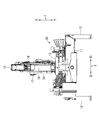
- FIG. 1 is a side view of a vehicle-mounted crane 10 including an operation lever device 30 according to the present embodiment.
- FIG. 2 is a rear view of the vehicle-mounted crane 10 including the operation lever device 30.
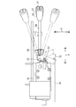
- FIG. 3 is a front view showing the operation lever device 30.
- FIG. 4 is a perspective view showing the operation lever 31 in a stacked state in the operation lever device 30.
- FIG. 5 is a plan view for explaining the operation of the operation lever 31 that is horizontally rotated.
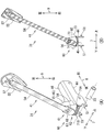
- FIG. 6 is a perspective view showing the operation lever 31.
- 7A and 7B are diagrams illustrating the operation lever 31, in which FIG. 7A is a plan view, FIG. 7B is a rear view, and FIG. 7C is a bottom view.
- FIGS. 9A and 9B are diagrams showing the coupling mechanism 60 of the operation lever 31, where FIG. 8A is a cross-sectional perspective view, and FIG. FIGS. 9A and 9B are diagrams illustrating the coupling mechanism 100 of the operation lever 31 according to the first modification, where FIG. 9A is a perspective view, FIG. 9B is a sectional perspective view, and FIG. 9C is a sectional front view.
- 10A and 10B are diagrams illustrating the coupling mechanism 110 of the operation lever 31 according to the second modification, where FIG. 10A is a perspective view of the fork 32, and FIG. 10B is a perspective view and a plan view of the proximal end portion 56 of the handle 41.
- FIG. 11A is a cross-sectional perspective view of the base end portion 56 of the fork 32 and the handle 41
- FIG. 4 is a cross-sectional front view of a proximal end portion of 41.
- FIG. FIG. 12 is a side view showing the coupling mechanism 60 of the operation lever 31 according to another modification.
- 1 and 2 are a left side view and a rear view of the vehicle-mounted crane 10.
- the vehicle-mounted crane 10 is mounted on a work vehicle and is driven by a hydraulic mechanism that uses the engine of the work vehicle as a drive source.
- the direction indicated by reference numeral 8 is the traveling direction of the work vehicle on which the vehicle-mounted crane 10 is mounted, and this direction is defined as the front-rear direction 8.
- a direction indicated by reference numeral 7 is defined as a vertical direction 7 (generally a vertical direction), and a direction orthogonal to the vertical direction 7 and the front-rear direction 8 is defined as a horizontal direction 9.
- the vehicle-mounted crane 10 includes a main beam 11, a jack 12, a swivel base 13, a swivel post 14, a boom 15, a hoisting cylinder 16, a winch 17, a wire rope 18, and a hook. 19 is mainly provided.
- the vehicle-mounted crane 10 has a main beam 11 fixed on the frame of the work vehicle.
- a slide beam extending in the left-right direction 9 is disposed in the main beam 11 formed in a box shape having a rectangular cross section, and the jack 12 supported by the slide beam extends and contacts the ground, thereby ensuring the stability of the vehicle.
- the swivel base 13 is provided on the main beam 11 and is rotatable around a rotation center axis along the vertical direction 7.
- the swivel post 14 is erected on the swivel base 13 and rotates together with the swivel base 13.
- the boom 15 is provided at the upper end of the turning post 14.
- the base end portion 15A of the boom 15 is connected to the turning post 14 via a undulation center pin, and the undulation operation is possible.
- the boom 15 includes a base boom 21, an intermediate boom 22, and a top boom 23.
- the intermediate boom 22 and the top boom 23 are telescopically stored in the base boom 21. Thereby, the boom 15 is comprised so that expansion-contraction is possible.
- the hoisting cylinder 16 is for hoisting the boom 15.
- the boom 15 has a built-in telescopic cylinder, and the boom 15 expands and contracts when the telescopic cylinder expands and contracts.
- the winch 17 is provided inside the turning post 14. The winch 17 extends or retracts the wire rope 18.
- the wire rope 18 hangs around the tip 15B of the boom 15, and a hook 19 is provided at the tip.
- the wire rope 18 When the winch 17 is rotated in a predetermined direction, the wire rope 18 is wound around the winch 17 and the hook 19 is raised. When the winch 17 is rotated in the anti-predetermined direction, the wire rope 18 is unwound from the winch 17 and the hook 19 is lowered.
- FIG. 3 is a front view showing the operation lever device 30,
- FIG. 4 is a perspective view showing the operation lever 31 in a stacked state in the operation lever device 30, and
- FIG. 5 is an operation lever that is rotated horizontally. It is a top view for demonstrating the operation
- FIG. 4 is a perspective view showing the operation lever 31 in a stacked state in the operation lever device 30, and
- FIG. 5 is an operation lever that is rotated horizontally. It is a top view for demonstrating the operation
- the vehicle-mounted crane 10 is hydraulically driven by a hydraulic circuit and includes an operation lever device 30 for operating the hydraulic circuit.
- the operation lever device 30 is for operating expansion and contraction of the boom 15, raising and lowering of the boom 15, rotation of the winch 17, rotation of the swivel base 13, and expansion and contraction of the jack 12.
- the operation lever device 30 includes a boom telescopic operation lever 31A, a boom raising / lowering operation lever 31B, a winch operation lever 31C, a turning operation lever 31D, and jack operation levers 31E and 31F, and is collectively referred to as an operation lever 31.
- one operation lever 31 corresponding to each operation is provided on each of the left and right sides of the vehicle-mounted crane 10.
- a base end portion 56 (see FIG. 5) of the operation lever 31 is provided with a fork 32 (corresponding to a “base” described in claims), which will be described later (see FIG. 4).
- the fork 32 is rotatably provided on a rotation shaft 33 (corresponding to a “predetermined rotation axis” recited in the claims) extending in the vertical direction 7.
- a pair of forks 32 arranged on the left and right are connected by a rod 34, and as shown in FIG. 5, when one operating lever 31 is turned, the corresponding other operating lever 31 rotates in conjunction with it. Move. As a result, the operator can operate from either the left or right side of the vehicle.
- FIG. 6 is a perspective view showing the operation lever 31.
- FIG. 7 is a plan view, a rear view, and a bottom view of the operation lever 31.
- FIG. 8 is a cross-sectional view of the operation lever 31 and shows a coupling mechanism 60 described later.
- the operation lever 31 includes a fork 32 and a handle 41.
- the following description of the operation lever 31 uses a state where the operation lever 31 provided on the left side of the vehicle is not rotated in the horizontal direction (a state where the operation lever 31 is in a neutral position with respect to rotation).
- the fork 32 includes a main body 42 and a holding frame 43.
- the main body 42 includes an upper plate 44, a lower plate 45, and a side plate 46.
- the upper plate 44 has a substantially rectangular plate shape extending in the front-rear direction 8 and the left-right direction 9.
- the lower plate 45 is positioned below the upper plate 44 with a space from the upper plate 44 and has a substantially rectangular plate shape extending in the front-rear direction 8 and the left-right direction 9.
- the side plate 46 has a substantially rectangular plate shape that extends in the up-down direction 7 and the front-rear direction 8, and has an edge in the short-side direction spanning a side edge 47 of the upper plate 44 and a side edge 48 of the lower plate 45. ing.
- the holding frame 43 will be described later.
- the fork 32 includes a rotation shaft insertion hole 51 that penetrates the upper plate 44 and the lower plate 45 in the vertical direction 7, and the rotation shaft 33 is inserted through the fork 32. Thereby, the fork 32 can be rotated in the horizontal direction around the rotation shaft 33.
- the handle 41 includes a main body portion 54, a grip portion 55, and a base end portion 56.
- the main body 54 has a straight cylindrical shape, and extends in the axial direction of the cylindrical shape.
- the grip portion 55 is one end portion of the main body portion 54 and has a handle 57 attached thereto.
- the handle 57 is provided so that an operator can easily grip the grip portion 55 of the handle 41.
- the base end portion 56 is formed at the other end portion of the main body portion 54 and has a flat plate shape. Details of the base end portion 56 will be described later.
- the operation lever 31 includes a connection mechanism 60.
- the handle 41 is connected to the fork 32 via the connection mechanism 60.
- the connecting mechanism 60 allows the handle 41 to change its attitude relative to the fork 32. That is, as shown in FIG. 8, the angle formed by the upper surface of the upper plate 44 of the fork 32 (corresponding to a “virtual plane” described in the claims) and the main body 54 of the handle 41 is adjusted.
- the connecting mechanism 60 includes a support portion 61 and a rotation restricting portion 62.
- the support portion 61 includes a holding frame 43, bolts 63 (corresponding to “support pins” described in claims), and a base end portion 56 of the handle 41.
- the holding frame 43 includes a front plate 65 and a rear plate 66 (corresponding to “a pair of walls” recited in the claims).
- the front plate 65 and the rear plate 66 are installed on the side plate 46 of the fork 32 on the side opposite to the side on which the upper plate 44 and the lower plate 45 are located.
- the front plate 65 and the rear plate 66 have a semi-elliptical flat plate shape extending perpendicularly to the side plate 46 and extending in the up-down direction 7 and the left-right direction 9, and are spaced apart.
- the front plate 65 and the rear plate 66 include bolt insertion holes 67.
- the bolt insertion hole 67 is a circular through hole that penetrates the front plate 65 and the rear plate 66 in the front-rear direction 8.
- a female screw is formed on the inner periphery of the bolt insertion hole 67 of the front plate 65.
- the bolt 63 is inserted from the bolt insertion hole 67 of the rear plate 66 toward the bolt insertion hole 67 of the front plate 65 and is screwed into the bolt insertion hole 67 of the front plate 65.
- the handle 41 includes a bolt insertion hole 68.
- the bolt insertion hole 68 is a circular through hole that penetrates the flat plate shape of the proximal end portion 56 of the handle 41.
- the bolt 63 can be inserted into the bolt insertion hole 68.
- the rotation restricting portion 62 is a pair of gears 71A and 71B formed on the fork 32 and the base end portion 56 of the handle 41 and meshing with each other.
- the gear 71 ⁇ / b> A of the fork 32 is located between the front plate 65 and the rear plate 66 of the holding frame 43 in the side plate 46 of the fork 32.
- the gear 71 ⁇ / b> A is an internal gear having gear teeth on a virtual inner peripheral surface 73 (see FIG. 8B) around the central axis 72 (see FIG. 8B) of the bolt insertion hole 67.
- the gear 71 ⁇ / b> B of the base end portion 56 of the handle 41 is located on the end surface of the base end portion 56.
- the gear 71 ⁇ / b> B is an external gear having gear teeth on a virtual outer peripheral surface 74 (see FIG. 8B) centered on the central axis 72 of the bolt insertion hole 68.
- the gear 71 ⁇ / b> A and the gear 71 ⁇ / b> B are engaged with each other in a state in which 72 is coincident. Therefore, the gear 71A and the gear 71B can be fitted at a desired relative angle, and in this state, the bolt 63 is inserted into the bolt insertion hole 67 and the bolt insertion hole 68, and is screwed into the front plate 65. As a result, the handle 41 is fixed to the fork 32 at a desired angle.
- the fork 32 swings around the rotation shaft 33.
- the angle of the handle 41 with respect to the fork 32 is adjusted by the connecting mechanism 60.
- the positions of the gripping portions 55 of the handles 41 are adjusted so as to be separated from each other. Therefore, even if a plurality of handles 41 having the same shape are arranged side by side, the positions of the gripping portions 55 are separated from each other (see FIG. 3). As a result, the types of parts constituting the operation lever 31 are reduced, and the cost for manufacturing and managing the operation lever 31 is suppressed.
- the base end portion 56 of the handle 41 is rotatably supported by the support portion 61 of the coupling mechanism 60, so that the base end portion 56 of the handle 41 is positioned at a desired angle with respect to the fork 32. Then, when the angle of the handle 41 is determined by the rotation restricting portion 62 of the connection mechanism 60, the base end portion 56 of the handle 41 is fixed at a desired angle. That is, the structure of the coupling mechanism 60 is very simple.
- the bolt 63 is inserted into the bolt insertion hole 67 of the holding frame 43 and the bolt insertion hole 68 of the handle 41, so that the proximal end portion 56 of the handle 41 is located with respect to the holding frame 43. And is supported rotatably. Then, the gear 71A formed on the fork 32 and the gear 71B formed on the base end portion 56 of the handle 41 mesh with each other, whereby the angle of the base end portion 56 of the handle 41 is determined.
- the connection mechanism 60 is simpler and the positioning of the handle 41 is reliable.
- the holding frame 43 includes a front plate 65 and a rear plate 66.
- the base end portion 56 of the handle 41 is sandwiched between the front plate 65 and the rear plate 66 of the holding frame 43, and the base end portion 56 is disposed on both sides in the front-rear direction 8. Hold from. Therefore, the handle 41 can be more firmly fixed to the fork 32.
- the fork 32 Since the fork 32 has a circular rotation shaft insertion hole 51 through which the columnar rotation shaft 33 is inserted, the fork 32 can be easily rotated around the rotation shaft 33.
- FIG. 9 shows the coupling mechanism 100 of the operation lever 31 according to the first modification of the present embodiment, (A) and (B) are perspective views, and (C) are sectional views.
- connection mechanism 100 shown in FIG. 9 instead of the connection mechanism 60 (see FIG. 8), a connection mechanism 100 shown in FIG. 9 may be employed.
- the connection mechanism 100 includes a support portion 101 and a rotation restricting portion 102 as with the connection mechanism 60.
- the configuration of the support portion 101 is substantially the same as that of the support portion 61. In the description of this modification, the same components as those of the operation lever 31 shown in FIG.
- the rotation restricting portion 102 is formed in a plurality of through holes 103 (corresponding to “engagement grooves” described in claims) formed in the side plate 46 of the fork 32 and a base end portion 56 of the handle 41. And a single protrusion 104.
- the left surface of the side plate 46 is positioned on the virtual inner peripheral surface 105 centered on the central axis 72 of the bolt insertion hole 67. It is formed as follows.
- the through hole 103 is formed between the front plate 65 and the rear plate 66 in the side plate 46 of the fork 32.
- the through hole 103 passes through the side plate 46 in a direction orthogonal to the central axis 72 of the bolt insertion hole 67.
- the plurality of through-holes 103 are arranged at intervals in the circumferential direction around the central axis 72.
- the through hole 103 is formed in an inner surface shape, for example, a rectangle, into which the protrusion 104 of the handle 41 can be fitted.
- the protrusion 104 formed on the base end portion 56 of the handle 41 protrudes from the end surface of the base end portion 56 in the axial direction of the handle 41.
- the protrusion 104 has a cross-sectional shape (for example, a rectangle) that can be fitted into the through hole 103 of the fork 32.
- each through-hole 103 is formed along the virtual inner peripheral surface 105 centering on the central axis 72, the projection 104 and the desired through-hole are in a state where the bolt insertion hole 67 and the bolt insertion hole 68 are aligned.
- the hole 103 is fitted.
- the bolts 63 are inserted into the bolt insertion holes 67 and the bolt insertion holes 68 and screwed into the front plate 65, whereby the handle 41 is fixed at a desired angle with respect to the fork 32.
- the bolt 63 disposed on the holding frame 43 passes through the base end portion 56 of the handle 41, so that the base end portion 56 of the handle 41 can rotate with respect to the holding frame 43. Supported. Then, the base end portion of the handle 41 is selectively engaged with the plurality of through holes 103 provided in parallel with the side plate 46 of the fork 32 and the protrusion 104 provided on the base end portion 56 of the handle 41. 56 angles are determined.
- the fork 32 of this modification can be formed by sheet metal pressing from a single flat plate (for example, a metal plate) in which the main body 42 and the holding frame 43 can be plastically deformed. Therefore, the fork 32 can be manufactured with a simple process.
- the front plate 65 of the holding frame 43 is formed by making a semi-elliptical cut into the side plate 46 of the fork 32 and bending the semi-elliptical portion to the left rear. The Therefore, a semi-elliptical through hole 106 is formed in the side plate 46 of the fork 32.
- FIG. 10 is a diagram illustrating the coupling mechanism 110 of the operation lever 31 according to the second modification of the present embodiment.
- a connection mechanism 110 shown in FIG. 10 may be employed.
- the connection mechanism 110 shown in FIG. 10 has the same support part 61 as the connection mechanism 60 shown in FIG. In the description of this modification, the same components as those of the operation lever 31 shown in FIG.
- the rotation restricting portion 111 includes four fitting surfaces 112A, 112B, 113A, and 113B formed on the holding frame 43 of the fork 32 and the base end portion 56 of the handle 41 (“engagement described in claims”). Part)).
- Each fitting surface 112A, 112B, 113A, 113B has a face gear shape.
- the fitting surface 112 ⁇ / b> A is formed on the rear surface of the front plate 65 of the holding frame 43.
- the fitting surface 113 ⁇ / b> A is formed on the front surface of the rear plate 66 of the holding frame 43.
- the fitting surfaces 112 ⁇ / b> A and 113 ⁇ / b> A are positioned around the bolt insertion hole 67 with the central axis 72 of the bolt insertion hole 67 as the center.
- the fitting surface 112 ⁇ / b> B is formed on the front surface of the base end portion 56 of the handle 41.
- the fitting surface 113 ⁇ / b> B is formed on the rear surface of the base end portion 56 of the handle 41.
- the fitting surfaces 112 ⁇ / b> B and 113 ⁇ / b> B are located around the bolt insertion hole 68 around the central axis 72 of the bolt insertion hole 68.
- the base end portion 56 of the handle 41 is sandwiched between the front plate 65 and the rear plate 66 of the holding frame 43. With the central axis 72 of the bolt insertion hole 67 and the central axis 72 of the bolt insertion hole 68 aligned, the bolt 63 is inserted into the bolt insertion hole 67 and the bolt insertion hole 68, and the nut 64 is tightened. Thereby, two pairs of fitting surfaces 112A, 112B, 113A, and 113B are fitted together. That is, the fitting surface 112A and the fitting surface 112B are fitted, and the fitting surface 113A and the fitting surface 113B are fitted.
- the base end portion 56 of the handle 41 is moved. It is easy to insert between the front plate 65 and the rear plate 66 of the holding frame 43. Since the fitting surfaces 112A, 112B, 113A, 113B are formed around the central axis 72, the two pairs of fitting surfaces 112A, 112B in a state where the bolt insertion hole 67 and the bolt insertion hole 68 are aligned. , 113A and 113B are fitted. Therefore, the bolt 63 is inserted into the bolt insertion hole 67 and the bolt insertion hole 68 and the nut 64 is tightened, whereby the handle 41 is fixed to the fork 32 at a desired angle.
- the bolt 63 disposed on the holding frame 43 passes through the base end portion 56 of the handle 41, so that the base end portion 56 of the handle 41 is rotatably supported with respect to the holding frame 43.
- steering-wheel 41 is determined because fitting surface 112A, 112B, 113A, 113B mutually meshes
- the main body 42 and the holding frame 43 are formed by sheet metal pressing from a single flat plate (for example, a metal plate) that can be plastically deformed, similarly to the fork 32 according to the first modification. Can do.
- the holding frame 43 has the front plate 65 and the rear plate 66, but may have only one of the front plate 65 and the rear plate 66.
- the bolt 63 may be screwed with a female screw formed in the bolt insertion hole 67 of the front plate 65 or may be screwed with the nut 64.
- the means for fixing the bolt insertion hole 67 and the bolt insertion hole 68 may not be a bolt. For example, after the pin is inserted into the bolt insertion hole 67 and the bolt insertion hole 68, both ends of the pin are deformed so as to be larger than the diameter of the bolt insertion hole 67, so that the bolt insertion hole 67 and the bolt insertion hole 68 are formed. It may be fixed.
- the through hole 103 of the fork 32 may be a recess that does not penetrate.
- the wall 107 (see FIG. 9) that partitions each through-hole 103 does not need to extend continuously between the front plate 65 and the rear plate 66. That is, it may be a protrusion protruding backward from the rear surface of the front plate 65 or a protrusion protruding forward from the front surface of the rear plate 66.
- the rotation restricting portion 62 may be a bolt insertion hole.
- the base end portion 56 of the handle 41 is provided with a bolt insertion hole as the rotation restricting portion 62 in addition to the bolt insertion hole 68.
- the holding frame 43 has a plurality of bolt insertion holes as the rotation restricting portion 62 in addition to the bolt insertion holes 67.
- the plurality of bolt insertion holes are arranged apart from each other on the circumference so that the center is located on the circumference around the central axis 72 of the bolt insertion hole 67.
- the bolt insertion hole as the rotation restricting portion 62 in the handle 41 is replaced with any of the plurality of bolt insertion holes as the rotation restricting portion 62 in the holding frame 43.
- the handle 41 is fixed at a desired angle with respect to the fork 32 by tightening the two bolt insertion holes with two pairs of bolts and nuts.
- the rotation restricting portion 62 is in a direction parallel to the central axis 72 of the bolt insertion hole 68 at the base end portion 56 of the handle 41 (forward in FIGS. 11 and 12).
- a protruding convex portion 121 (see FIG. 12) and a plurality of concave portions 122 (corresponding to “engagement grooves” recited in the claims) recessed forward on the rear surface of the front plate 65 of the holding frame 43. Also good.
- the recesses 122 are spaced apart from each other on the circumference centered on the central axis 72 of the bolt insertion hole 67 (see FIG. 11B). As shown in FIG.
- the convex portion 121 as the rotation restricting portion 62 in the handle 41 is used as the rotation restricting portion 62 in the holding frame 43.
- the bolt 41 is screwed with respect to the female screw formed on the inner periphery of the bolt insertion hole 67, whereby the handle 41 is fixed at a desired angle with respect to the fork 32.
- the holding frame 43 has the rear plate 66 (see FIG. 7C). However, as shown in FIG. Adopted.
- the number of gear teeth of the gear 71A in the fork 32 is larger than the number of gear teeth of the gear 71B in the proximal end portion 56 of the handle 41. May be the same as the number of gear teeth of the gear 71B or less than the number of gear teeth of the gear 71B.
- a plurality of bolt insertion holes as the rotation restricting portion 62 described above may be formed in the base end portion 56 of the handle 41.
- the bolt insertion hole is a square hole, and a prismatic pin may be inserted into the bolt insertion hole of the square hole.
Landscapes
- Engineering & Computer Science (AREA)
- Mechanical Engineering (AREA)
- Life Sciences & Earth Sciences (AREA)
- Agronomy & Crop Science (AREA)
- Physics & Mathematics (AREA)
- General Physics & Mathematics (AREA)
- Automation & Control Theory (AREA)
- Steering Devices For Bicycles And Motorcycles (AREA)
- Jib Cranes (AREA)
- Mechanical Control Devices (AREA)
Abstract
Description
32・・・フォーク(基台)
33・・・回動軸
41・・・ハンドル
43・・・保持フレーム
51・・・回動軸挿通孔
56・・・基端部
60・・・連結機構
61・・・支持部
62・・・回動規制部
63・・・ボルト(支持ピン)
65・・・前板(壁)
66・・・後板(壁)
71A,71B・・・ギア
103・・・貫通孔(係合溝)
104・・・突起
122・・・凹部(係合溝)
112A,112B,113A,113B・・・嵌合面(係合部)
Claims (7)
- 所定の回動軸線を中心として回動することにより当該回動軸線と直交する仮想平面上を揺動することができる基台と、
当該基台に設けられ、上記回動軸線を中心とする円周方向に操作されることにより上記基台を揺動させる棒状のハンドルと、
当該ハンドル及び上記基台の間に介在され、上記ハンドルの軸方向と上記仮想平面とのなす角度を調整可能に、上記ハンドルを上記基台に連結する連結機構とを備えた操作レバー。 - 上記連結機構は、
上記ハンドルの基端部を回動可能に支持する支持部と、
上記ハンドルの回動を規制して当該ハンドルと上記仮想平面とがなす角度を調整する回動規制部とを有する請求項1に記載の操作レバー。 - 上記支持部は、
上記基台に設けられ、上記ハンドルの基端部を保持する保持フレームと、
上記保持フレームに配置され、上記ハンドルの基端部を上記保持フレームに対して回動自在に支持する支持ピンとを有し、
上記回動規制部は、
上記基台及び保持フレームの少なくとも一方と上記ハンドルの基端部とに形成され、互いに係合する一対の係合部を有し、
上記係合部は、上記ハンドルの基端部が上記保持フレームに対して回動された複数の回動角度において互いに係合する請求項2に記載の操作レバー。 - 上記係合部は、上記支持ピンの中心軸を中心とする円周方向に沿って上記基台に並設された複数の係合溝と、
上記ハンドルの基端部に設けられ、当該基端部が回動することにより上記係合溝に選択的に係合する突起とを有する請求項3に記載の操作レバー。 - 上記係合部は、
上記保持フレームと上記基端部とが対向する各対向面に、互いに係合するように形成されている請求項3に記載の操作レバー。 - 上記保持フレームは、上記基端部を挟み込む一対の壁を有する請求項3から5のいずれかに記載の操作レバー。
- 上記基台は、上記回動軸線を中心とする円形の貫通孔を有する請求項1から6のいずれかに記載の操作レバー。
Priority Applications (2)
| Application Number | Priority Date | Filing Date | Title |
|---|---|---|---|
| KR1020187023243A KR102079888B1 (ko) | 2016-02-19 | 2016-08-08 | 조작 레버 |
| CN201680081763.0A CN108700909B (zh) | 2016-02-19 | 2016-08-08 | 操作杆 |
Applications Claiming Priority (2)
| Application Number | Priority Date | Filing Date | Title |
|---|---|---|---|
| JP2016-030467 | 2016-02-19 | ||
| JP2016030467A JP6672872B2 (ja) | 2016-02-19 | 2016-02-19 | 操作レバー |
Publications (1)
| Publication Number | Publication Date |
|---|---|
| WO2017141464A1 true WO2017141464A1 (ja) | 2017-08-24 |
Family
ID=59625800
Family Applications (1)
| Application Number | Title | Priority Date | Filing Date |
|---|---|---|---|
| PCT/JP2016/073286 Ceased WO2017141464A1 (ja) | 2016-02-19 | 2016-08-08 | 操作レバー |
Country Status (4)
| Country | Link |
|---|---|
| JP (1) | JP6672872B2 (ja) |
| KR (1) | KR102079888B1 (ja) |
| CN (1) | CN108700909B (ja) |
| WO (1) | WO2017141464A1 (ja) |
Citations (2)
| Publication number | Priority date | Publication date | Assignee | Title |
|---|---|---|---|---|
| JPS55159417U (ja) * | 1979-04-28 | 1980-11-15 | ||
| JPH0583521U (ja) * | 1992-04-13 | 1993-11-12 | 安司 吉川 | ラチェット機構 |
Family Cites Families (4)
| Publication number | Priority date | Publication date | Assignee | Title |
|---|---|---|---|---|
| JP2647592B2 (ja) * | 1992-02-28 | 1997-08-27 | 古河機械金属株式会社 | 車両搭載用クレーンの操作レバー装置 |
| JPH1136368A (ja) * | 1997-07-24 | 1999-02-09 | Hitachi Constr Mach Co Ltd | 建設機械の操作レバー装置 |
| KR100240189B1 (ko) * | 1997-12-29 | 2000-01-15 | 김형벽 | 토건중장비인 굴삭기의 위치조정형 주행레바 |
| CN104085795B (zh) * | 2014-06-25 | 2017-01-04 | 长治清华机械厂 | 直臂式随车吊的中位操作装置 |
-
2016
- 2016-02-19 JP JP2016030467A patent/JP6672872B2/ja active Active
- 2016-08-08 CN CN201680081763.0A patent/CN108700909B/zh active Active
- 2016-08-08 WO PCT/JP2016/073286 patent/WO2017141464A1/ja not_active Ceased
- 2016-08-08 KR KR1020187023243A patent/KR102079888B1/ko active Active
Patent Citations (2)
| Publication number | Priority date | Publication date | Assignee | Title |
|---|---|---|---|---|
| JPS55159417U (ja) * | 1979-04-28 | 1980-11-15 | ||
| JPH0583521U (ja) * | 1992-04-13 | 1993-11-12 | 安司 吉川 | ラチェット機構 |
Also Published As
| Publication number | Publication date |
|---|---|
| KR20180103976A (ko) | 2018-09-19 |
| JP2017145140A (ja) | 2017-08-24 |
| CN108700909A (zh) | 2018-10-23 |
| CN108700909B (zh) | 2021-02-09 |
| JP6672872B2 (ja) | 2020-03-25 |
| KR102079888B1 (ko) | 2020-02-20 |
Similar Documents
| Publication | Publication Date | Title |
|---|---|---|
| US20180022586A1 (en) | Mobile crane having adjustable ballast mounting apparatus | |
| JP2013530907A (ja) | クレーンブームの連繋構造 | |
| CA2828004C (en) | Crane machine with articulated arm | |
| WO2017141464A1 (ja) | 操作レバー | |
| JP5039077B2 (ja) | 建設機械用トラックフレーム | |
| CN110182699B (zh) | 一种爬升装置及自爬升起重机 | |
| JP6082849B2 (ja) | 作業車両、牽引装置の操作方法および牽引装置の組立方法 | |
| JP2011148010A (ja) | ポジショナを備えたロボットシステム | |
| JP2017001777A (ja) | ジブ張出格納機構 | |
| JP2019089626A (ja) | ピン挿入検出装置及びこれを備える作業機 | |
| JP4301322B2 (ja) | ジブ格納装置 | |
| WO2016194266A1 (ja) | ジブ張出格納機構 | |
| JP6013286B2 (ja) | 作業機のブーム | |
| US20250296817A1 (en) | Work machine | |
| JP6527091B2 (ja) | ポスト駆動装置 | |
| KR20130073573A (ko) | 리프팅 러그 핸들링 장치 | |
| JP6289911B2 (ja) | 杭打機 | |
| JP2012125094A (ja) | 弛度調整金具 | |
| JP2008253061A (ja) | バーニヤ金具を備えた耐張装置 | |
| JP5829725B1 (ja) | 車両用リフト装置 | |
| JP2002038512A (ja) | ボス及びブラケットの溶接構造物およびその溶接方法 | |
| KR20180116607A (ko) | 원터치형의 조립구조를 갖는 농업용 작업기 연결장치 | |
| US11753790B2 (en) | Cross-support assembly extending between and connecting two generally parallel lifting arms of a working machine | |
| JP2019070266A (ja) | 鉄骨柱の目違い修正用治具 | |
| JP2016137971A (ja) | アタッチメント |
Legal Events
| Date | Code | Title | Description |
|---|---|---|---|
| 121 | Ep: the epo has been informed by wipo that ep was designated in this application |
Ref document number: 16890601 Country of ref document: EP Kind code of ref document: A1 |
|
| ENP | Entry into the national phase |
Ref document number: 20187023243 Country of ref document: KR Kind code of ref document: A |
|
| WWE | Wipo information: entry into national phase |
Ref document number: 1020187023243 Country of ref document: KR |
|
| NENP | Non-entry into the national phase |
Ref country code: DE |
|
| 122 | Ep: pct application non-entry in european phase |
Ref document number: 16890601 Country of ref document: EP Kind code of ref document: A1 |