WO2017138559A1 - 遠心回転機械 - Google Patents
遠心回転機械 Download PDFInfo
- Publication number
- WO2017138559A1 WO2017138559A1 PCT/JP2017/004563 JP2017004563W WO2017138559A1 WO 2017138559 A1 WO2017138559 A1 WO 2017138559A1 JP 2017004563 W JP2017004563 W JP 2017004563W WO 2017138559 A1 WO2017138559 A1 WO 2017138559A1
- Authority
- WO
- WIPO (PCT)
- Prior art keywords
- sealing device
- casing
- impeller
- cover
- rotating machine
- Prior art date
- Legal status (The legal status is an assumption and is not a legal conclusion. Google has not performed a legal analysis and makes no representation as to the accuracy of the status listed.)
- Ceased
Links
Images



Classifications
-
- F—MECHANICAL ENGINEERING; LIGHTING; HEATING; WEAPONS; BLASTING
- F04—POSITIVE - DISPLACEMENT MACHINES FOR LIQUIDS; PUMPS FOR LIQUIDS OR ELASTIC FLUIDS
- F04D—NON-POSITIVE-DISPLACEMENT PUMPS
- F04D29/00—Details, component parts, or accessories
- F04D29/08—Sealings
-
- F—MECHANICAL ENGINEERING; LIGHTING; HEATING; WEAPONS; BLASTING
- F04—POSITIVE - DISPLACEMENT MACHINES FOR LIQUIDS; PUMPS FOR LIQUIDS OR ELASTIC FLUIDS
- F04D—NON-POSITIVE-DISPLACEMENT PUMPS
- F04D29/00—Details, component parts, or accessories
- F04D29/08—Sealings
- F04D29/16—Sealings between pressure and suction sides
-
- F—MECHANICAL ENGINEERING; LIGHTING; HEATING; WEAPONS; BLASTING
- F04—POSITIVE - DISPLACEMENT MACHINES FOR LIQUIDS; PUMPS FOR LIQUIDS OR ELASTIC FLUIDS
- F04D—NON-POSITIVE-DISPLACEMENT PUMPS
- F04D29/00—Details, component parts, or accessories
- F04D29/40—Casings; Connections of working fluid
- F04D29/42—Casings; Connections of working fluid for radial or helico-centrifugal pumps
- F04D29/44—Fluid-guiding means, e.g. diffusers
-
- F—MECHANICAL ENGINEERING; LIGHTING; HEATING; WEAPONS; BLASTING
- F04—POSITIVE - DISPLACEMENT MACHINES FOR LIQUIDS; PUMPS FOR LIQUIDS OR ELASTIC FLUIDS
- F04D—NON-POSITIVE-DISPLACEMENT PUMPS
- F04D29/00—Details, component parts, or accessories
- F04D29/70—Suction grids; Strainers; Dust separation; Cleaning
-
- F—MECHANICAL ENGINEERING; LIGHTING; HEATING; WEAPONS; BLASTING
- F16—ENGINEERING ELEMENTS AND UNITS; GENERAL MEASURES FOR PRODUCING AND MAINTAINING EFFECTIVE FUNCTIONING OF MACHINES OR INSTALLATIONS; THERMAL INSULATION IN GENERAL
- F16J—PISTONS; CYLINDERS; SEALINGS
- F16J15/00—Sealings
- F16J15/44—Free-space packings
- F16J15/447—Labyrinth packings
Definitions
- the present invention relates to a centrifugal rotating machine.
- This application claims priority on Japanese Patent Application No. 2016-021881 filed on Feb. 8, 2016, the contents of which are incorporated herein by reference.
- the centrifugal rotating machine has an impeller provided on a rotating shaft and a casing that covers the impeller.
- the impeller of the centrifugal rotating machine rotates in the casing and foreign particles such as dust and sand enter between the impeller and the casing, the impeller and the casing may be damaged.
- Patent Document 1 discloses a sizing device that reduces the amount of foreign particles entering a compressor of a gas turbine engine that is a kind of rotating machine.
- the foreign particles When foreign particles flow into the centrifugal rotating machine and the foreign particles come into contact with the rotating impeller, the foreign particles are ejected to the outside in the radial direction of the impeller and stay between the impeller and the casing. End up.
- the foreign particles staying between the impeller and the casing may cause wear inside the centrifugal rotating machine or damage the inside of the centrifugal rotating machine.
- the present invention provides a centrifugal rotating machine that can prevent the seal device from being worn or damaged by foreign particles flowing into the impeller portion of the centrifugal rotating machine.
- a first aspect of the present invention is a disk having a disk shape that rotates around an axis, and is provided on the surface facing the one side in the axial direction of the disk at a circumferential interval so that the disk is spaced from one side in the axial direction.
- An end wall surface defining a radial flow path extending in a radial direction between the cover end surface and the sealing device, and between the sealing device and the radial flow channel, than the sealing device; Is formed from every large material is centrifugal rotary machine further comprising a protective member for covering the surface facing the axial one side of the sealing device.
- the sealing device can be protected so that the sealing device is less likely to be worn or damaged due to the collision of the foreign particles with the sealing device.
- the protective member may be formed integrally with the casing and may have an annular shape protruding radially inward from the casing toward the axis of the disk.
- the protective member may be fixed to the sealing device.
- the protective member may be integrated by spraying on a surface of the sealing device that faces one side in the axial direction.
- the casing is connected to a radially inner side of the end wall surface and extends to one side in the axial direction to the impeller.
- An inlet-side inner peripheral surface that defines a fluid introduction flow path, and is formed in the casing and opens to a radially outer end of the end wall surface and the inlet-side inner peripheral surface.
- the seal device it is possible to prevent the seal device from being worn or damaged by foreign particles flowing into the impeller portion of the centrifugal rotating machine.
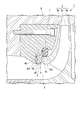
- FIG. 3 is an enlarged view of the periphery of the radial flow path in FIG. 2. It is an expanded sectional view of the radial direction channel of the centrifugal rotating machine concerning a 2nd embodiment of the present invention.
- FIG. 1 is a cross-sectional view showing a schematic configuration of a centrifugal rotating machine according to a first embodiment of the present invention.
- FIG. 2 is an enlarged view of the impeller of FIG.
- FIG. 3 is an enlarged view of the periphery of the radial flow path of FIG.
- FIG. 1 illustrates a cross section when the centrifugal rotating machine 1 is cut so that the rotating shaft 2 is divided into two on a virtual plane parallel to the extending direction of the rotating shaft 2.
- A indicates the moving direction of fluid (for example, process gas), and O indicates the axis of the rotating shaft 2.
- the centrifugal rotating machine 1 includes a rotating shaft 2, an impeller 3, a pair of bearings 5 ⁇ / b> A and 5 ⁇ / b> B, a casing 6, and a sealing device 7.
- the rotating shaft 2 is a columnar member that extends in the same direction as the direction in which the axis O extends (axial direction).
- the rotating shaft 2 is rotatably supported by bearings 5A and 5B at both ends (first end and second end) positioned in the direction in which the axis O extends.
- the rotating shaft 2 rotates in one direction.
- the rotating shaft 2 has an outer peripheral surface 2a that is a curved surface.
- the impeller 3 is provided on the outer peripheral surface 2a of the rotating shaft 2 located between the bearing 5A and the bearing 5B.
- the impeller 3 includes a disk 3a, a cover 3b, and a plurality of blades 3c.
- the disk 3a gradually increases in diameter toward the outer side in the radial direction of the rotary shaft 2 from one end (first end) of the rotary shaft 2 in the axial direction toward the other end (second end). Is provided.
- the shape of the disk 3a can be a substantially disk shape, for example.
- the axis of the disk 3 a is located on the axis O of the rotary shaft 2.
- the axis of the disk 3a is also referred to as “axis O”.
- the cover 3b is provided so as to face the disk 3a.
- the cover 3b covers the plurality of blades 3c.
- the plurality of blades 3c are provided radially outside the disk 3a so as to be separated from the disk 3a.
- the blade 3c defines and forms a flow path that extends radially outward from one axial direction side (first end side) of the disk 3a.
- a multistage impeller group 3A is constituted by a plurality of impellers 3 arranged coaxially in the extending direction of the axis O of the rotating shaft 2.
- the bearing 5 ⁇ / b> A is provided at one end of the rotating shaft 2.
- the bearing 5 ⁇ / b> B is provided at the other end of the rotating shaft 2.
- the casing 6 is cylindrical and supports the bearings 5A and 5B from the outside.
- the casing 6 accommodates the rotating shaft 2, the impeller 3, and the seal device 7 on the radially inner side.
- the casing 6 is configured such that the rotating shaft 2 and the impeller 3 can rotate with respect to the casing 6.
- the casing 6 has a casing channel 6a, a suction port 6b, connection channels 6c and 6d, and a discharge port 6e.
- the casing flow path 6a, the suction port 6b, the connection flow paths 6c and 6d, and the discharge port 6e are provided in a portion of the casing 6 corresponding to the region where the multistage impeller group 3A is disposed.
- the casing 6 has an end wall surface 6f, an inlet-side inner peripheral surface 6g, and a reflux path 6h.
- the end wall surface 6f, the inlet-side inner peripheral surface 6g, and the reflux path 6h are provided for each impeller 3 with respect to each impeller 3 constituting the multistage impeller group 3A in the casing 6.
- the casing 6 has a protection portion 6i (protection member) that protects the surface 7a facing the one side in the axial direction of the disk 3a in the sealing device 7.
- the casing flow path 6a is formed inside the casing 6 and connects the flow paths of the impellers 3 adjacent in the axial direction.
- the casing flow path 6 a is configured to have an annular shape around the axis O in the casing 6 positioned outside the rotating shaft 2.
- the suction port 6b is provided in the casing 6 located on the side close to the bearing 5A. The suction port 6b sucks the fluid A and guides the sucked fluid A to the casing channel 6a through the connection channel 6c.
- connection flow path 6c is formed in the casing 6, and connects the casing flow path 6a and the suction port 6b.
- connection flow path 6d is provided in the casing 6, and connects the discharge port 6e and the casing flow path 6a.
- the discharge port 6e discharges the fluid that has passed through the connection flow path 6d to the outside of the casing 6.
- the end wall surface 6f is disposed to face the cover end surface 3b1 facing one side in the axial direction of the cover 3b and extends in the radial direction.
- the end wall surface 6f is disposed on one side in the axial direction with respect to the cover end surface 3b1. Furthermore, the end wall surface 6f defines a radial flow path 8 between the cover end surface 3b1.
- the radial flow path 8 is a flow path into which foreign particles P contained in the fluid flowing in when the centrifugal rotating machine 1 operates can enter.
- the foreign particle P that has entered the radial flow path 8 moves outward in the radial direction of the impeller 3 by contacting the cover 3 b of the rotating impeller 3.
- the inlet-side inner peripheral surface 6g is connected to the radially inner side of the end wall surface 6f.
- the inlet-side inner peripheral surface 6g extends from the radially inner end of the end wall surface 6f to one side in the axial direction.
- the inlet-side inner peripheral surface 6 g defines a fluid introduction passage 9 for the impeller 3.
- the reflux path 6h opens to the radially outer end of the end wall surface 6f and the inlet-side inner peripheral surface 6g, so that the radial flow path 8 and the introduction flow path 9 To communicate.
- the shape of the reflux path 6h may be, for example, a continuous ring centered on the axis O of the disk 3a, or a plurality of paths spaced in the circumferential direction centered on the axis O of the disk 3a. If the reflux path 6h has a continuous annular shape in the circumferential direction centering on the axis O of the disk 3a, the foreign particles P are likely to enter the reflux path 6h, which is advantageous in terms of foreign matter removal performance. It is advantageous in the aerodynamic performance of the centrifugal rotating machine 1 that a plurality of the reflux paths 6h are provided apart from each other in the circumferential direction around the axis O of the disk 3a.
- the protective portion 6i has a plate shape that protrudes from the radially outer side of the sealing device 7 toward the radially inner side in the casing 6. Further, when viewed from the direction of the axis O of the disk 3a, the protection part 6i covers the sealing device 7 in an annular shape centered on the axis O.
- the clearance between the protection unit 6 i and the sealing device 7 is determined in consideration of the size of the foreign particle P that is supposed to be mixed in the centrifugal rotating machine 1. The size is set so as not to enter the gap between the two.
- the protruding end 6j of the protective part 6i protruding inward in the radial direction is directed to the outer peripheral surface 3b2 of the cover 3b of the impeller 3.
- the clearance between the protective part 6i and the cover 3b of the impeller 3 takes into account the size of the foreign particles P that are supposed to be mixed in the centrifugal rotating machine 1, and the foreign particles P are separated from the protective part 6i and the impeller 3
- the size is set so as not to enter the gap between the two.
- the size of the gap between the protection unit 6i and the cover 3b of the impeller 3 is determined by the protection unit 6i when the wear of the seal device 7 is taken into consideration during normal operation of the centrifugal rotating machine 1 of the present embodiment. It is preferable that the size does not contact 3b.
- the protective part 6 i is preferably made of a material having a hardness higher than that of the sealing device 7. In the present embodiment, since the material of the casing 6 has a higher altitude than the material of the sealing device 7, the protective part 6 i can be integrally molded as a part of the casing 6.
- a protective member (not shown) separate from the casing 6 may be fixed to the casing 6.
- the material of the protective member (not shown) can be selected independently of the material of the casing 6.
- the sealing device 7 is arranged in the gap between the impeller 3 and the casing 6.
- the sealing device 7 of this embodiment is a so-called labyrinth seal.
- the sealing device 7 seals the gap between the impeller 3 and the casing 6 with a predetermined clearance with respect to the cover 3 b of the impeller 3.
- the centrifugal rotating machine 1 of the present embodiment will be described.
- the impeller 3 moves the foreign particle P to the outside in the radial direction of the impeller 3.
- the foreign particles P approach the vicinity of the gap between the protection unit 6i and the sealing device 7, but in this embodiment, the foreign particles P can collide with the protection unit 6i but do not collide with the sealing device 7.
- the foreign particle P moves to the outer side in the radial direction of the end wall surface 6f without passing through the gap between the protection unit 6i and the sealing device 7.
- the foreign particle P moves to the radially outer side of the end wall surface 6f, the foreign particle P enters the reflux path 6h and moves to the inlet side inner peripheral surface 6g.
- the foreign particles P that have reached the inlet-side inner peripheral surface 6 g move to the impeller 3 by the fluid flowing through the introduction flow path 9.
- the protection unit 6 i prevents the foreign particle P from colliding with the sealing device 7
- the sealing by the foreign particle P colliding with the sealing device 7 is performed.
- the sealing device 7 can be protected from wear and damage to the device 7.
- the foreign particles P can be returned to the introduction flow path 9 through the reflux path 6h without the foreign particles P staying in the vicinity of the radially outer end of the end wall surface 6f. For this reason, the foreign particle P that has reached the vicinity of the end portion on the radially outer side of the end wall surface 6 f can be quickly removed from the gap between the impeller 3 and the casing 6.
- FIG. 4 is an enlarged cross-sectional view around the radial flow path of the centrifugal rotating machine according to the present embodiment.
- the member for protecting the sealing device 7 is the same as the protection unit 6i disclosed in the first embodiment, as shown in FIG. It is fixed to. That is, the centrifugal rotating machine 10 of the present embodiment has a protection member 11 fixed to the seal device 7 instead of the protection unit 6i.
- the protection member 11 shown in FIG. 4 is a plate-like member fixed to the surface 7 a facing the one side in the axis O direction of the disk 3 a in the sealing device 7.
- the protection member 11 When viewed from the direction of the axis O of the disk 3a, the protection member 11 has an annular shape that covers the seal device 7 in the same manner as the protection portion 6i disclosed in the first embodiment.
- the fixing method of the protection member 11 and the sealing device 7 is not particularly limited.
- the protective member 11 is bolted to the sealing device 7.
- the protective member 11 may be integrated by spraying on the surface of the disk 3a that faces one side in the axis O direction.
- the protective member 11 since the protective member 11 and the sealing device 7 are fixed, the protective member 11 follows the movement of the sealing device 7, so that the size of the gap between the protective member 11 and the cover 3 b varies. Less is.
- the concrete structure is not restricted to this embodiment, The design change etc. of the range which does not deviate from the summary of this invention are included.
- the protective part is made of a material having a hardness higher than that of the sealing device.
- the hardness of the protective part (protective member) is smaller than the hardness of the sealing device. Even if it exists, a sealing device can be protected from the collision of the foreign particle with respect to a sealing device.
- a jet passage for flowing a fluid flowing out from the gap between the protective portion (protective member) and the cover through the gap between the sealing device and the cover to the return path may be opened in the end wall surface.
Landscapes
- Engineering & Computer Science (AREA)
- General Engineering & Computer Science (AREA)
- Mechanical Engineering (AREA)
- Structures Of Non-Positive Displacement Pumps (AREA)
- Sealing Using Fluids, Sealing Without Contact, And Removal Of Oil (AREA)
Abstract
遠心回転機械は、ディスク3a、ブレード3c、及びカバー3bを備えるインペラ3と、インペラ3を径方向内側に収容するとともに、カバー3bの外周面3b2との間に隙間を形成するケーシング6と、前記隙間をシールするシール装置7と、を備える。ケーシング6は、カバー3bの軸線方向一方側を向くカバー端面3b1及びシール装置7の軸線方向一方側に間隔をあけて配置され、径方向に延びる径方向流路を画成する端壁面6fを有する。シール装置7と径方向流路8との間に、シール装置7よりも硬度の大きい材料から形成されてシール装置7を覆う防護部6iをさらに備える。
Description
本発明は、遠心回転機械に関する。
本願は、2016年2月8日に出願された特願2016-021881号について優先権を主張し、その内容をここに援用する。
本願は、2016年2月8日に出願された特願2016-021881号について優先権を主張し、その内容をここに援用する。
一般的に、遠心回転機械は、回転軸に設けられたインペラと、このインペラを覆うケーシングとを有している。遠心回転機械のインペラがケーシング内で回転する際にインペラとケーシングとの間に埃や砂などの異物粒子が進入すると、インペラやケーシングを痛めることがある。
たとえば特許文献1には、回転機械の一種であるガスタービンエンジンの圧縮機に入る異物粒子の量を減らす分粒装置が開示されている。
たとえば特許文献1には、回転機械の一種であるガスタービンエンジンの圧縮機に入る異物粒子の量を減らす分粒装置が開示されている。
遠心回転機械の内部に異物粒子が流入してしまった場合に、回転中のインペラに異物粒子が接触すると、異物粒子はインペラの径方向外側へとはじき出されてインペラとケーシングとの間に滞留してしまう。インペラとケーシングとの間に滞留した異物粒子は、遠心回転機械の内部の摩耗を進行させたり、遠心回転機械の内部を破損させたりする可能性がある。
本発明は、遠心回転機械のインペラ部分まで流入した異物粒子によるシール装置の摩耗や破損を防ぐことができる遠心回転機械を提供する。
本発明の第一態様は、軸線回りに回転する円盤状をなすディスク、該ディスクの軸線方向一方側を向く面に周方向に間隔をあけて設けられることで互いの間に軸線方向一方側から径方向外側に向かう流路を区画形成するブレード、及び、該ブレードを径方向外側から覆うカバーを備えるインペラと、該インペラを径方向内側に収容するとともに、前記カバーの外周面との間に隙間を形成するケーシングと、前記隙間をシールするシール装置と、を備え、前記ケーシングは、前記カバーの軸線方向一方側を向くカバー端面及び前記シール装置の軸線方向一方側に間隔をあけて配置され、カバー端面及びシール装置との間で径方向に延びる径方向流路を画成する端壁面を有し、前記シール装置と前記径方向流路との間に、前記シール装置よりも硬度の大きい材料から形成されて前記シール装置の軸線方向一方側を向く面を覆う防護部材をさらに備える遠心回転機械である。
上記態様の遠心回転機械において、回転中のインペラのカバーに異物粒子が衝突すると、異物粒子はインペラの径方向外側に移動される。ここで、異物粒子はシール装置には衝突せず防護部材に衝突するので、シール装置への異物粒子の衝突によるシール装置の摩耗や破損が起こりにくくなるようにシール装置を保護できる。
本発明の第二態様では、第一態様において、前記防護部材は、前記ケーシングと一体成型され、前記ケーシングから前記ディスクの軸線へ向かって径方向内側に突出する環状をなしていてもよい。
本発明の第三態様では、第一態様において、前記防護部材は、前記シール装置に固定されていてもよい。
本発明の第四態様では、第三態様において、前記防護部材は、前記シール装置における前記軸線方向一方側を向く面に溶射により一体化されていてもよい。
本発明の第五態様では、第一態様から第四態様のいずれか一つにおいて、前記ケーシングは、前記端壁面の径方向内側に接続されて、前記軸線方向一方側に延びて前記インペラへの流体の導入流路を画成する入口側内周面と、前記ケーシング内に形成されて、前記端壁面の径方向外側の端部と前記入口側内周面とに開口することで、前記径方向流路と前記導入流路とを連通させる還流路と、を有していてもよい。
本発明によれば、遠心回転機械のインペラ部分まで流入した異物粒子によるシール装置の摩耗や破損を防ぐことができる。
以下、図面を参照して本発明を適用した実施の形態について詳細に説明する。なお、以下の説明で用いる図面は、本発明の実施の形態の構成を説明するためのものである。図示される各部の大きさや厚さや寸法等は、実際の遠心回転機械、及びシール装置の寸法関係とは異なる場合がある。
(第1実施形態)
本発明の第1実施形態について説明する。図1は、本発明の第1実施形態に係る遠心回転機械の概略構成を示す断面図である。図2は、図1のインペラの拡大図である。図3は、図2の径方向流路周辺の拡大図である。図1では、遠心回転機械1を回転軸2の延在方向に対して平行な仮想平面で、回転軸2を2分割するように、遠心回転機械1を切断した場合の断面を図示している。
図1において、Aは流体(例えば、プロセスガス)の移動方向、Oは回転軸2の軸線をそれぞれ示している。
本発明の第1実施形態について説明する。図1は、本発明の第1実施形態に係る遠心回転機械の概略構成を示す断面図である。図2は、図1のインペラの拡大図である。図3は、図2の径方向流路周辺の拡大図である。図1では、遠心回転機械1を回転軸2の延在方向に対して平行な仮想平面で、回転軸2を2分割するように、遠心回転機械1を切断した場合の断面を図示している。
図1において、Aは流体(例えば、プロセスガス)の移動方向、Oは回転軸2の軸線をそれぞれ示している。
図1及び図2を参照するに、本実施形態の遠心回転機械1は、回転軸2と、インペラ3と、一対の軸受5A,5Bと、ケーシング6と、シール装置7と、を備える。
回転軸2は、軸線Oの延びる方向(軸線方向)と同じ方向に延びる柱状の部材である。回転軸2は、軸線Oの延びる方向に位置する両端部(第一端部及び第二端部)が軸受5A及び5Bによって回転可能に支持されている。回転軸2は、一方向に回転する。回転軸2は、曲面とされた外周面2aを有する。
回転軸2は、軸線Oの延びる方向(軸線方向)と同じ方向に延びる柱状の部材である。回転軸2は、軸線Oの延びる方向に位置する両端部(第一端部及び第二端部)が軸受5A及び5Bによって回転可能に支持されている。回転軸2は、一方向に回転する。回転軸2は、曲面とされた外周面2aを有する。
インペラ3は、軸受5Aと軸受5Bとの間に位置する回転軸2の外周面2aに設けられている。インペラ3は、ディスク3aと、カバー3bと、複数のブレード3cと、を有する。
ディスク3aは、軸線方向における回転軸2の一方の端部(第一端部)から他方の端部(第二端部)に向かうにつれて、回転軸2の径方向の外側に漸次拡径するように設けられている。ディスク3aの形状は、例えば、略円盤状とすることができる。ディスク3aの軸線は、回転軸2の軸線O上に位置する。以下、ディスク3aの軸線についても「軸線O」と表記する。
カバー3bは、ディスク3aと対向するように設けられている。カバー3bは、複数のブレード3cを覆っている。
複数のブレード3cは、ディスク3aの外側に、ディスク3aから離間するように、放射状に設けられている。ブレード3cは、ディスク3aの軸線方向一方側(第一端部側)から径方向外側に向かう流路を区画形成する。
ディスク3aは、軸線方向における回転軸2の一方の端部(第一端部)から他方の端部(第二端部)に向かうにつれて、回転軸2の径方向の外側に漸次拡径するように設けられている。ディスク3aの形状は、例えば、略円盤状とすることができる。ディスク3aの軸線は、回転軸2の軸線O上に位置する。以下、ディスク3aの軸線についても「軸線O」と表記する。
カバー3bは、ディスク3aと対向するように設けられている。カバー3bは、複数のブレード3cを覆っている。
複数のブレード3cは、ディスク3aの外側に、ディスク3aから離間するように、放射状に設けられている。ブレード3cは、ディスク3aの軸線方向一方側(第一端部側)から径方向外側に向かう流路を区画形成する。
本実施形態では、回転軸2の軸線Oの延在方向に同軸状に並べられた複数のインペラ3によって多段式インペラ群3Aが構成されている。
軸受5Aは、回転軸2の一方の端部に設けられている。軸受5Bは、回転軸2の他方の端部に設けられている。
ケーシング6は、筒状とされており、軸受5A及び5Bを外側から支持している。ケーシング6は、回転軸2、インペラ3、及びシール装置7を径方向内側に収容している。
ケーシング6は、ケーシング6に対して回転軸2及びインペラ3を、回転可能な構成とされている。
ケーシング6は、ケーシング流路6aと、吸込口6bと、接続流路6c及び6dと、排出口6eとを有する。ケーシング流路6a、吸込口6b、接続流路6c,6d、及び排出口6eは、ケーシング6のうち、多段式インペラ群3Aの配置された領域に対応する部分に設けられている。
さらに、ケーシング6は、端壁面6fと、入口側内周面6gと、還流路6hとを有している。端壁面6f、入口側内周面6g、及び還流路6hは、ケーシング6のうち、多段式インペラ群3Aを構成する各インペラ3に対して、インペラ3毎に設けられている。
また、ケーシング6は、シール装置7においてディスク3aの軸方向一方側に向く面7aを保護する防護部6i(防護部材)を有している。
ケーシング6は、ケーシング6に対して回転軸2及びインペラ3を、回転可能な構成とされている。
ケーシング6は、ケーシング流路6aと、吸込口6bと、接続流路6c及び6dと、排出口6eとを有する。ケーシング流路6a、吸込口6b、接続流路6c,6d、及び排出口6eは、ケーシング6のうち、多段式インペラ群3Aの配置された領域に対応する部分に設けられている。
さらに、ケーシング6は、端壁面6fと、入口側内周面6gと、還流路6hとを有している。端壁面6f、入口側内周面6g、及び還流路6hは、ケーシング6のうち、多段式インペラ群3Aを構成する各インペラ3に対して、インペラ3毎に設けられている。
また、ケーシング6は、シール装置7においてディスク3aの軸方向一方側に向く面7aを保護する防護部6i(防護部材)を有している。
ケーシング流路6aは、ケーシング6の内部に形成されて、軸線方向で隣り合うインペラ3の流路同士を接続している。ケーシング流路6aは、回転軸2の外側に位置するケーシング6において、軸線Oを中心とした環状となるように構成されている。
吸込口6bは、軸受5Aに近い側に位置するケーシング6に設けられている。吸込口6bは、流体Aを吸い込み、接続流路6cを介して、吸い込んだ流体Aをケーシング流路6aに導く。
吸込口6bは、軸受5Aに近い側に位置するケーシング6に設けられている。吸込口6bは、流体Aを吸い込み、接続流路6cを介して、吸い込んだ流体Aをケーシング流路6aに導く。
接続流路6cは、ケーシング6内に形成されており、ケーシング流路6aと吸込口6bとを接続している。接続流路6dは、ケーシング6に内設されており、排出口6eとケーシング流路6aとを接続している。
排出口6eは、接続流路6dを経由した流体をケーシング6の外部に排出する。
排出口6eは、接続流路6dを経由した流体をケーシング6の外部に排出する。
端壁面6fは、カバー3bの軸線方向一方側を向くカバー端面3b1に対向配置されて径方向に延びている。端壁面6fは、カバー端面3b1に対して軸線方向一方側に配置されている。さらに、端壁面6fは、カバー端面3b1との間に径方向流路8を画成している。
径方向流路8は、遠心回転機械1の動作時に流入する流体に含まれる異物粒子Pが進入可能な流路である。径方向流路8に進入した異物粒子Pは、回転するインペラ3のカバー3bに接触することでインペラ3の径方向外側へと移動する。
入口側内周面6gは、端壁面6fの径方向内側に接続されている。入口側内周面6gは、端壁面6fの径方向内側の端部から軸線方向一方側へ延びている。入口側内周面6gは、インペラ3への流体の導入流路9を画成する。
図2及び図3に示すように、還流路6hは、端壁面6fの径方向外側の端部と入口側内周面6gとに開口することで、径方向流路8と導入流路9とを連通させる。還流路6hの形状は、たとえば、ディスク3aの軸線Oを中心とする一続きの環状や、ディスク3aの軸線Oを中心とする周方向に離間する複数の通路状などであってよい。
還流路6hがディスク3aの軸線Oを中心とする周方向に一続きの環状をなしていると、異物粒子Pが還流路6hに入りやすいので、異物除去性能において有利である。
還流路6hがディスク3aの軸線Oを中心とする周方向に離間して複数設けられていると、遠心回転機械1の空力性能において有利である。
還流路6hがディスク3aの軸線Oを中心とする周方向に一続きの環状をなしていると、異物粒子Pが還流路6hに入りやすいので、異物除去性能において有利である。
還流路6hがディスク3aの軸線Oを中心とする周方向に離間して複数設けられていると、遠心回転機械1の空力性能において有利である。
防護部6iは、ケーシング6においてシール装置7の径方向外側から径方向内側へ向かって突出する板状をなしている。また、ディスク3aの軸線O方向から見たときに、防護部6iは、軸線Oを中心とする環状をなしてシール装置7を覆っている。防護部6iとシール装置7との間の隙間は、遠心回転機械1内に混入することが想定される異物粒子Pの大きさを考慮して、異物粒子Pが防護部6iとシール装置7との間の隙間に入り込まない程度の大きさに設定される。
図3に示すように、径方向内側へ向かって突出している防護部6iの突出端6jは、インペラ3のカバー3bの外周面3b2に向けられている。防護部6iとインペラ3のカバー3bとの間の隙間は、遠心回転機械1内に混入することが想定される異物粒子Pの大きさを考慮して、異物粒子Pが防護部6iとインペラ3との間の隙間に入り込まない程度の大きさに設定される。また、防護部6iとインペラ3のカバー3bとの間の隙間の大きさは、本実施形態の遠心回転機械1の通常の動作時におけるシール装置7の摩耗を考慮したときに防護部6iがカバー3bに接触しない大きさであることが好ましい。
本実施形態では、インペラ3より上流側が低圧でありインペラ3より下流側が高圧であるので、シール装置7とカバー3bとの間では、ディスク3aの軸線O方向一方側へ向かって流体が流れる。このため、防護部6iとシール装置7との間の隙間よりも小さな異物粒子Pであっても防護部6iとシール装置7との間の隙間からの噴流に押し返される。
防護部6iは、シール装置7よりも硬度の大きな材料からなることが好ましい。本実施形態では、ケーシング6の材料がシール装置7の材料よりも高い高度を有しているので、ケーシング6の一部として防護部6iを一体成型可能である。
なお、ケーシング6に防護部6iが形成されていることに代えて、ケーシング6とは別体の防護部材(不図示)がケーシング6に固定されていてもよい。この場合、不図示の防護部材の材質は、ケーシング6の材質とは独立して選択可能である。
図2に示すように、シール装置7は、インペラ3とケーシング6との隙間に配されている。本実施形態のシール装置7は、所謂ラビリンスシールである。シール装置7は、インペラ3のカバー3bに対して所定のクリアランスを有した状態で、インペラ3とケーシング6との隙間をシールする。
本実施形態の遠心回転機械1の作用について説明する。
本実施形態の遠心回転機械1の動作時には、流体中の異物粒子Pがカバー3bに接触するとインペラ3によって異物粒子Pがインペラ3の径方向外側に移動する。防護部6iとシール装置7との間の隙間の近傍まで異物粒子Pが近付くが、本実施形態では、異物粒子Pは防護部6iに衝突し得るがシール装置7には衝突しない。また、本実施形態では、異物粒子Pは、防護部6iとシール装置7との間の隙間を通過せずに、端壁面6fの径方向外側まで移動する。端壁面6fの径方向外側まで異物粒子Pが移動すると、異物粒子Pは還流路6hへ進入して入口側内周面6gまで移動する。入口側内周面6gに到達した異物粒子Pは、導入流路9を流れる流体によってインペラ3へと移動する。
本実施形態の遠心回転機械1の動作時には、流体中の異物粒子Pがカバー3bに接触するとインペラ3によって異物粒子Pがインペラ3の径方向外側に移動する。防護部6iとシール装置7との間の隙間の近傍まで異物粒子Pが近付くが、本実施形態では、異物粒子Pは防護部6iに衝突し得るがシール装置7には衝突しない。また、本実施形態では、異物粒子Pは、防護部6iとシール装置7との間の隙間を通過せずに、端壁面6fの径方向外側まで移動する。端壁面6fの径方向外側まで異物粒子Pが移動すると、異物粒子Pは還流路6hへ進入して入口側内周面6gまで移動する。入口側内周面6gに到達した異物粒子Pは、導入流路9を流れる流体によってインペラ3へと移動する。
このように、本実施形態の遠心回転機械1によれば、異物粒子Pがシール装置7に衝突するのを防護部6iが防いでいるので、シール装置7に異物粒子Pが衝突することによるシール装置7の摩耗や破損からシール装置7を保護できる。
また、本実施形態では、端壁面6fの径方向外側の端部近傍に異物粒子Pが滞留せずに還流路6hを通じて導入流路9へ異物粒子Pを戻すことができる。このため、端壁面6fの径方向外側の端部近傍に達した異物粒子Pをインペラ3とケーシング6との隙間から速やかに除去できる。
(第2実施形態)
本発明の第2実施形態について説明する。図4は、本実施形態に係る遠心回転機械の径方向流路周辺の拡大断面図である。
本実施形態の遠心回転機械10(図1参照)は、第1実施形態に開示された防護部6iと同様にシール装置7を保護するための部材が、図4に示すように、シール装置7に固定されている。
すなわち、本実施形態の遠心回転機械10は、防護部6iに代えて、シール装置7に固定された防護部材11を有している。
本発明の第2実施形態について説明する。図4は、本実施形態に係る遠心回転機械の径方向流路周辺の拡大断面図である。
本実施形態の遠心回転機械10(図1参照)は、第1実施形態に開示された防護部6iと同様にシール装置7を保護するための部材が、図4に示すように、シール装置7に固定されている。
すなわち、本実施形態の遠心回転機械10は、防護部6iに代えて、シール装置7に固定された防護部材11を有している。
図4に示す防護部材11は、シール装置7において、ディスク3aの軸線O方向一方側を向く面7aに固定された板状部材である。ディスク3aの軸線O方向から見たときに、防護部材11は、第1実施形態に開示された防護部6iと同様にシール装置7を覆う環状をなしている。
防護部材11とシール装置7との固定方法は特に限定されない。たとえば、防護部材11は、シール装置7にボルト止めされる。また、シール装置7において、ディスク3aの軸線O方向一方側を向く面に防護部材11が溶射により一体化されてもよい。
防護部材11とシール装置7との固定方法は特に限定されない。たとえば、防護部材11は、シール装置7にボルト止めされる。また、シール装置7において、ディスク3aの軸線O方向一方側を向く面に防護部材11が溶射により一体化されてもよい。
本実施形態では、防護部材11とシール装置7とが固定されているので、シール装置7の動きに防護部材11が追従するので、防護部材11とカバー3bとの間の隙間の大きさの変動が少ない。
以上、本発明の実施形態について図面を参照して詳述したが、具体的な構成はこの実施形態に限られるものではなく、本発明の要旨を逸脱しない範囲の設計変更等も含まれる。
例えば、上記実施形態では、防護部(防護部材)はシール装置よりも硬度の大きい材料からなる例が開示されているが、防護部(防護部材)の硬度がシール装置の硬度よりも小さい場合であってもシール装置に対する異物粒子の衝突からシール装置を保護することができる。
例えば、上記実施形態では、防護部(防護部材)はシール装置よりも硬度の大きい材料からなる例が開示されているが、防護部(防護部材)の硬度がシール装置の硬度よりも小さい場合であってもシール装置に対する異物粒子の衝突からシール装置を保護することができる。
また、本実施形態において、シール装置とカバーとの隙間と通じて防護部(防護部材)とカバーとの隙間から流れ出す流体を還流路へ流すための噴流通路が端壁面に開口されていてもよい。
上記遠心回転機械によれば、遠心回転機械のインペラ部分まで流入した異物粒子によるシール装置の摩耗や破損を防ぐことができる。
1,10 遠心回転機械
2 回転軸
2a 外周面
3 インペラ
3a ディスク
3A 多段式インペラ群
3b カバー
3b1 カバー端面
3b2 外周面
3c ブレード
5A 軸受
5B 軸受
6 ケーシング
6a ケーシング流路
6b 吸込口
6c 接続流路
6d 接続流路
6e 排出口
6f 端壁面
6g 入口側内周面
6h 還流路
6i 防護部
6j 防護部の突出端
7 シール装置
8 径方向流路
9 導入流路
10 遠心回転機械
11 防護部材
2 回転軸
2a 外周面
3 インペラ
3a ディスク
3A 多段式インペラ群
3b カバー
3b1 カバー端面
3b2 外周面
3c ブレード
5A 軸受
5B 軸受
6 ケーシング
6a ケーシング流路
6b 吸込口
6c 接続流路
6d 接続流路
6e 排出口
6f 端壁面
6g 入口側内周面
6h 還流路
6i 防護部
6j 防護部の突出端
7 シール装置
8 径方向流路
9 導入流路
10 遠心回転機械
11 防護部材
Claims (5)
- 軸線回りに回転する円盤状をなすディスク、該ディスクの軸線方向一方側を向く面に周方向に間隔をあけて設けられることで互いの間に軸線方向一方側から径方向外側に向かう流路を区画形成するブレード、及び、該ブレードを径方向外側から覆うカバーを備えるインペラと、
該インペラを径方向内側に収容するとともに、前記カバーの外周面との間に隙間を形成するケーシングと、
前記隙間をシールするシール装置と、を備え、
前記ケーシングは、前記カバーの軸線方向一方側を向くカバー端面及び前記シール装置の軸線方向一方側に間隔をあけて配置され、カバー端面及びシール装置との間で径方向に延びる径方向流路を画成する端壁面を有し、
前記シール装置と前記径方向流路との間に、前記シール装置よりも硬度の大きい材料から形成されて前記シール装置の軸線方向一方側を向く面を覆う防護部材をさらに備える
遠心回転機械。 - 前記防護部材は、前記ケーシングと一体成型され、前記ケーシングから前記ディスクの軸線へ向かって径方向内側に突出する環状をなしている
請求項1に記載の遠心回転機械。 - 前記防護部材は、前記シール装置に固定されている
請求項1に記載の遠心回転機械。 - 前記防護部材は、前記シール装置における前記軸線方向一方側を向く面に溶射により一体化されている
請求項3に記載の遠心回転機械。 - 前記ケーシングは、
前記端壁面の径方向内側に接続されて、前記軸線方向一方側に延びて前記インペラへの流体の導入流路を画成する入口側内周面と、
前記ケーシング内に形成されて、前記端壁面の径方向外側の端部と前記入口側内周面とに開口することで、前記径方向流路と前記導入流路とを連通させる還流路と、
を有する請求項1から請求項4のいずれか一項に記載の遠心回転機械。
Applications Claiming Priority (2)
| Application Number | Priority Date | Filing Date | Title |
|---|---|---|---|
| JP2016-021881 | 2016-02-08 | ||
| JP2016021881A JP2017141684A (ja) | 2016-02-08 | 2016-02-08 | 遠心回転機械 |
Publications (1)
| Publication Number | Publication Date |
|---|---|
| WO2017138559A1 true WO2017138559A1 (ja) | 2017-08-17 |
Family
ID=59563150
Family Applications (1)
| Application Number | Title | Priority Date | Filing Date |
|---|---|---|---|
| PCT/JP2017/004563 Ceased WO2017138559A1 (ja) | 2016-02-08 | 2017-02-08 | 遠心回転機械 |
Country Status (2)
| Country | Link |
|---|---|
| JP (1) | JP2017141684A (ja) |
| WO (1) | WO2017138559A1 (ja) |
Citations (3)
| Publication number | Priority date | Publication date | Assignee | Title |
|---|---|---|---|---|
| JPH0575481U (ja) * | 1992-03-11 | 1993-10-15 | 東芝エンジニアリング株式会社 | 水車主軸の封水装置 |
| JPH0771398A (ja) * | 1993-09-01 | 1995-03-14 | Kobe Steel Ltd | 遠心圧縮機 |
| JPH07174097A (ja) * | 1993-12-20 | 1995-07-11 | Kobe Steel Ltd | 遠心圧縮機 |
-
2016
- 2016-02-08 JP JP2016021881A patent/JP2017141684A/ja active Pending
-
2017
- 2017-02-08 WO PCT/JP2017/004563 patent/WO2017138559A1/ja not_active Ceased
Patent Citations (3)
| Publication number | Priority date | Publication date | Assignee | Title |
|---|---|---|---|---|
| JPH0575481U (ja) * | 1992-03-11 | 1993-10-15 | 東芝エンジニアリング株式会社 | 水車主軸の封水装置 |
| JPH0771398A (ja) * | 1993-09-01 | 1995-03-14 | Kobe Steel Ltd | 遠心圧縮機 |
| JPH07174097A (ja) * | 1993-12-20 | 1995-07-11 | Kobe Steel Ltd | 遠心圧縮機 |
Also Published As
| Publication number | Publication date |
|---|---|
| JP2017141684A (ja) | 2017-08-17 |
Similar Documents
| Publication | Publication Date | Title |
|---|---|---|
| JP5314256B2 (ja) | 回転流体機械のシール装置および回転流体機械 | |
| US10066750B2 (en) | Rotary machine | |
| CN105587346B (zh) | 密封装置以及涡轮机械 | |
| US10605270B2 (en) | Side-channel blower for an internal combustion engine, comprising a wide interrupting gap | |
| CN104813082B (zh) | 密封装置以及旋转机械 | |
| US20170241427A1 (en) | Seal mechanism and rotating machine | |
| WO2016043090A1 (ja) | 回転機械 | |
| US11519287B2 (en) | Rotating machine | |
| JP6777400B2 (ja) | 遠心回転機械 | |
| JP2018135815A (ja) | 遠心回転機械 | |
| JP5737065B2 (ja) | 圧縮機シール装置 | |
| JP6071644B2 (ja) | 多段遠心式流体機械 | |
| WO2017138559A1 (ja) | 遠心回転機械 | |
| JP6809793B2 (ja) | 遠心回転機械 | |
| JP2014084803A (ja) | 遠心式流体機械 | |
| KR102583275B1 (ko) | 쉬라우드 임펠러 조립체 | |
| US10876544B2 (en) | Rotary machine and diaphragm | |
| US20190078583A1 (en) | Impeller, rotary machine, and impeller manufacturing method | |
| US11898461B2 (en) | Axial flow turbine | |
| JP6700893B2 (ja) | 羽根車、回転機械 | |
| JP6986426B2 (ja) | タービン | |
| JP2015090144A (ja) | シール装置、および、回転機械 | |
| JP2007154735A (ja) | 回転機械のスワール防止装置 |
Legal Events
| Date | Code | Title | Description |
|---|---|---|---|
| 121 | Ep: the epo has been informed by wipo that ep was designated in this application |
Ref document number: 17750280 Country of ref document: EP Kind code of ref document: A1 |
|
| NENP | Non-entry into the national phase |
Ref country code: DE |
|
| 122 | Ep: pct application non-entry in european phase |
Ref document number: 17750280 Country of ref document: EP Kind code of ref document: A1 |