WO2017138324A1 - 接合方法 - Google Patents
接合方法 Download PDFInfo
- Publication number
- WO2017138324A1 WO2017138324A1 PCT/JP2017/001823 JP2017001823W WO2017138324A1 WO 2017138324 A1 WO2017138324 A1 WO 2017138324A1 JP 2017001823 W JP2017001823 W JP 2017001823W WO 2017138324 A1 WO2017138324 A1 WO 2017138324A1
- Authority
- WO
- WIPO (PCT)
- Prior art keywords
- metal member
- auxiliary member
- auxiliary
- joining
- metal
- Prior art date
- Legal status (The legal status is an assumption and is not a legal conclusion. Google has not performed a legal analysis and makes no representation as to the accuracy of the status listed.)
- Ceased
Links
Images



























Classifications
-
- B—PERFORMING OPERATIONS; TRANSPORTING
- B23—MACHINE TOOLS; METAL-WORKING NOT OTHERWISE PROVIDED FOR
- B23K—SOLDERING OR UNSOLDERING; WELDING; CLADDING OR PLATING BY SOLDERING OR WELDING; CUTTING BY APPLYING HEAT LOCALLY, e.g. FLAME CUTTING; WORKING BY LASER BEAM
- B23K20/00—Non-electric welding by applying impact or other pressure, with or without the application of heat, e.g. cladding or plating
- B23K20/12—Non-electric welding by applying impact or other pressure, with or without the application of heat, e.g. cladding or plating the heat being generated by friction; Friction welding
Definitions
- the present invention relates to a joining method for joining metal members by friction stir.
- Patent Document 1 discloses a joining method in which a first metal member and a second metal member are joined by friction stirring.
- the joining method after the first metal member and the second metal member are butted together to form a butted portion, only the stirring pin of the rotary tool is brought into contact with the first metal member and the second metal member.
- friction stirring is performed.
- Patent Document 2 a first metal member and a second metal member are overlapped to form a superposed portion, and then a rotary tool is inserted from the surface of the second metal member to friction stir weld the superposed portion.
- a joining method is described. In the friction stir welding, friction stirring is performed in a state where only the stirring pin is in contact with the second metal member.
- Patent Document 3 an abutting portion in which the height changes by abutting the end surfaces of metal members whose surface height changes is formed, and only the stirring pin of the rotary tool is brought into contact with the abutting portion of the metal members.
- a joining method is described in which friction stir is performed in a heated state.
- JP 2013-39613 A Japanese Patent Laid-Open No. 2015-139800 JP-A-2015-199119
- an object of the present invention is to provide a joining method that can prevent metal shortage at the joint.
- the present invention provides a joining method for joining a first metal member and a second metal member using a rotary tool having a stirring pin, the first metal member and the second metal member.
- the rotating tool is relatively moved along the abutting portion in a state where only the stirring pin is in contact with the first metal member, the second metal member, and the auxiliary member.
- a friction stirring step of joining the metal member, the second metal member, and the auxiliary member are examples of joining the metal member, the second metal member, and the auxiliary member.
- this invention is a joining method which joins a 1st metal member and a 2nd metal member using the rotary tool provided with the stirring pin, Comprising: Said 1st metal member and said 2nd metal member are faced
- the first metal member and the second metal member are joined, and in addition to the first metal member and the second metal member, the auxiliary member is also simultaneously friction stir welded, whereby Shortage can be prevented.
- a removing step of removing the auxiliary member on which the burr is formed from the first metal member or the second metal member since the burr can be removed together with the auxiliary member, the removal process becomes easy.
- the joining conditions it is preferable to set the joining conditions so that burrs generated in the friction stir welding are formed on the auxiliary member. According to such a joining method, the work of removing burrs can be performed more easily.
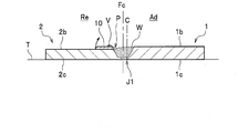
- the auxiliary member is arranged on one of the first metal member and the second metal member, and the other side of the butting portion is sandwiched so that the auxiliary member does not remain on the other side after the friction stirring step.
- the burr generated in the friction stir welding is formed on one side of the first metal member and the second metal member in the auxiliary member. It is preferable to set joining conditions.
- the work of removing burrs can be performed more easily.
- the auxiliary member is slightly protruded on the other side across the butting portion, it is possible to more reliably prevent metal shortage at the joint portion.
- this invention is a joining method which joins a 1st metal member and a 2nd metal member using the rotary tool provided with the stirring pin, Comprising: Said 1st metal member and said 2nd metal member are faced
- the rotary tool is moved relative to the first metal member, the second metal member, the second metal member, and the auxiliary member in a state where only the stirring pin is in contact with the first metal member, the second metal member, and the auxiliary member.
- this invention is a joining method which joins a 1st metal member and a 2nd metal member using the rotary tool provided with the stirring pin, Comprising: Said 1st metal member and said 2nd metal member are faced
- the first metal member and the second metal member are joined, and in addition to the first metal member and the second metal member, the auxiliary member is also simultaneously friction stir welded, whereby Shortage can be prevented.
- the plastic fluidized metal can fill the said clearance gap.
- this invention is a joining method which joins a 1st metal member and a 2nd metal member using the rotary tool provided with the stirring pin, Comprising: Said 1st metal member, Preparing the second metal member thinner than the first metal member, and abutting the end surfaces of the first metal member and the second metal member together to form a first step A butting step, an arranging step of arranging an auxiliary member on the first step, and inserting the rotating tool rotating from the surface side of the first metal member and the second metal member into the first step, A friction stir process in which only the stir pin is brought into contact with the first metal member, the second metal member, and the auxiliary member, and the rotating tool is relatively moved along the abutting portion to perform friction stir welding.
- this invention is a joining method which joins a 1st metal member and a 2nd metal member using the rotary tool provided with the stirring pin, Comprising: The end surfaces of said 1st metal member and said 2nd metal member are joined.
- a butting step for forming a butting portion and forming a first step, a disposing step for placing an auxiliary member on the first step, and rotation from the surface side of the first metal member and the second metal member The rotating tool is inserted into the first step, and the rotating tool is relatively moved along the abutting portion in a state where only the stirring pin is in contact with the first metal member, the second metal member, and the auxiliary member. And a friction stir process in which friction stir welding is performed.
- the first metal member and the second metal member are joined, and in addition to the first metal member and the second metal member, the auxiliary member is also simultaneously friction stir welded, whereby Shortage can be prevented.
- a removing step of removing the auxiliary member on which the burr is formed from the first metal member and the second metal member since the burr can be removed together with the auxiliary member, the removal process becomes easy.
- the joining conditions it is preferable to set the joining conditions so that burrs generated in the friction stir welding are formed on the auxiliary member. According to such a joining method, the work of removing burrs can be performed more easily.
- the auxiliary member is preferably arranged so that the surface of the first metal member and the surface of the auxiliary member are flush with each other. According to this joining method, the rotary tool can be easily inserted.
- the auxiliary member is preferably arranged so that the surface of the auxiliary member is higher than the surface of the first metal member. According to such a joining method, metal shortage at the joint can be reliably prevented.
- the auxiliary member is preferably arranged so that the surface of the auxiliary member is lower than the surface of the first metal member. According to this joining method, the auxiliary member can be easily removed.
- the friction stirring step it is preferable to perform friction stir welding along the abutting portion in a state where the rotation center axis of the rotary tool is shifted to the auxiliary member side with respect to the abutting portion.
- the friction stir welding is performed along the abutting portion in a state where the rotation center axis of the rotary tool is inclined toward the auxiliary member.
- this invention is a joining method which joins a 1st metal member and a 2nd metal member using the rotary tool provided with the stirring pin, Comprising: The surface of said 1st metal member A superposition step of superimposing the back surface of the second metal member to form a superposition part, a placement step of arranging an auxiliary member so as to be in surface contact with the surface of the second metal member, and the rotating stirring pin Inserting from the surface side of the auxiliary member, and rotating only the stirring pin in contact with the second metal member and the auxiliary member, or the first metal member, the second metal member and the auxiliary member And a friction stirring step of joining the first metal member, the second metal member, and the auxiliary member by moving the tool relative to each other.
- the overlapped portion is joined, and in addition to the first metal member and the second metal member, the auxiliary member is also simultaneously friction stir welded, thereby preventing the lack of metal in the joined portion. Thereby, it can prevent that a ditch
- the burr can be removed together with the auxiliary member.
- the stirring pin in the center of the auxiliary member. According to this joining method, metal shortage can be prevented more reliably. Further, the rotary tool can be easily inserted into the auxiliary member.
- the rotation center axis of the rotary tool and the reference line are Preferably, the agitation pins are moved relative to each other so that they overlap, and the joining conditions are set so that burrs are formed on the auxiliary member.
- the auxiliary member remains only on the side of the rotary tool, the removal process can be easily performed. Moreover, since the rotation center axis
- this invention is a joining method which joins a 1st metal member and a 2nd metal member using the rotary tool provided with the stirring pin, Comprising: At least the height of the surface changes A superposition step of superposing a back surface of the second metal member that changes the height of at least the back surface on the surface of the first metal member to form a superposition portion that changes in height; and a surface of the second metal member.
- Metal shortage can be prevented. Thereby, it can prevent that a ditch
- the method includes a removing step of removing the auxiliary member on which the burr is formed from the second metal member.
- the burr can be removed together with the auxiliary member.
- the stirring pin is inserted into a central portion of the auxiliary member.
- Such a method can more reliably prevent metal shortage. Further, the rotary tool can be easily inserted into the auxiliary member.
- a line that passes through the end face of the auxiliary member and is orthogonal to the first metal member and the second metal member is a reference line
- the rotation center axis of the rotary tool and the reference line are The agitation pins are moved relative to each other so as to overlap, and the joining conditions are set so that burrs are formed on the auxiliary member.
- the removal process can be easily performed. Moreover, since the rotation center axis
- the present invention is a joining method for joining a first metal member and a second metal member using a rotary tool equipped with a stirring pin, and the height of the surface changes.
- An abutting step of abutting the first metal member with the second metal member having a surface height change to form an abutting portion, and assisting the surface contact with the first metal member or the second metal member An arrangement step of arranging a member, and the rotating stirring pin is inserted into the abutting portion whose height changes from the surface side of the auxiliary member, and only the stirring pin of the rotating tool is the first metal member,
- a friction stirring step of joining the first metal member, the second metal member, and the auxiliary member by relatively moving the rotary tool along the abutting portion in a state where the second metal member and the auxiliary member are in contact with each other. And including And wherein the door.
- Metal shortage can be prevented. Thereby, it can prevent that a ditch
- the method includes a removing step of removing the auxiliary member on which the burr is formed from the first metal member or the second metal member.
- the burr can be removed together with the auxiliary member.
- the joining conditions are set so that burrs generated in the friction stir welding are formed on the auxiliary member.
- the present invention is a joining method for joining the first metal member and the second metal member using a rotary tool provided with a stirring pin, the surface of the first metal member and the surface of the first metal member changing A butting step of butting the second metal member whose height changes to form a butting portion, and an arranging step of arranging an auxiliary member so as to make surface contact with both the first metal member and the second metal member;
- the rotating stirring pin is inserted into the abutting portion whose height changes from the surface side of the auxiliary member, and only the stirring pin of the rotating tool is inserted into the first metal member, the second metal member, and the A friction stir process for joining the first metal member, the second metal member, and the auxiliary member by relatively moving the rotary tool along the abutting portion while being in contact with the auxiliary member.
- Metal shortage can be prevented. Thereby, it can prevent that a ditch
- the stirring pin can be inserted from the vicinity of the center of the auxiliary member to the butting portion, the stirring pin can be easily inserted into the auxiliary member.
- burrs are formed on the auxiliary members separated by the friction stirring step, but the burrs can be removed together with the auxiliary members in the removing step.
- the auxiliary member is arranged so as to slightly protrude to the other side across the butting portion while the auxiliary member is arranged on one of the first metal member and the second metal member,
- the joining conditions are set so that burrs generated in the friction stir welding are formed on either one of the first metal member and the second metal member among the auxiliary members.
- the slightly protruding portion of the auxiliary member is frictionally stirred by the stirring pin and compensated in the joint portion, so that metal shortage in the joint portion can be prevented in a balanced manner and more reliably.
- the stirring pin can be easily inserted into the auxiliary member.
- a spiral groove is engraved on the peripheral surface of the stirring pin, and when rotating the rotary tool clockwise, the spiral groove is engraved counterclockwise from the proximal end side to the distal end side of the stirring pin. And when rotating the said rotation tool counterclockwise, the said spiral groove is engraved clockwise toward the front end side from the base end side of the said stirring pin, It is characterized by the above-mentioned.
- the butting process is a process of matching the first metal member 1 and the second metal member 2 as shown in FIG.
- the first metal member 1 and the second metal member 2 are metal plate-like members.
- the material of the first metal member 1 and the second metal member 2 is not particularly limited as long as it is a metal that can be frictionally stirred.
- aluminum, aluminum alloy, copper, copper alloy, titanium, titanium alloy, magnesium, magnesium alloy, etc. May be selected as appropriate.
- board thickness of the 1st metal member 1 and the 2nd metal member 2 is equivalent.
- the plate thicknesses of the first metal member 1 and the second metal member 2 may be set as appropriate.
- the end surface 1a of the first metal member 1 and the end surface 2a of the second metal member 2 are butted to form a butting portion J1.
- the clearance gap may arise between the end surface 1a of the 1st metal member 1, and the end surface 2a of the 2nd metal member 2.
- FIG. The gap is about 1 mm.
- the surface 1b of the first metal member 1 and the surface 2b of the second metal member 2 are flush with each other.
- the placement step is a step of placing the auxiliary member 10 on the first metal member 1 or the second metal member 2.
- the auxiliary member 10 is a metal plate member.
- the auxiliary member 10 is not particularly limited as long as it is a metal capable of friction stirring, but in the present embodiment, the auxiliary member 10 is made of the same material as the first metal member 1 and the second metal member 2.
- board thickness of the auxiliary member 10 is suitably set so that the plasticization area
- the back surface 10c of the auxiliary member 10 and the front surface 2b of the second metal member 2 are brought into surface contact.
- the auxiliary member 10 is disposed so as to be in surface contact with only the second metal member 2 (or the first metal member 1). In this embodiment, it arrange
- the 1st metal member 1, the 2nd metal member 2, and the auxiliary member 10 are restrained to the mount frame T so that a movement is impossible using a jig
- the auxiliary member 10 is plate-shaped in this embodiment, another shape may be sufficient.
- the friction stirring step is a step of joining the butted portion J1 of the first metal member 1 and the second metal member 2 by friction stirring using the rotating tool F for bonding as shown in FIG.
- the joining rotary tool F includes a connecting portion F1 and a stirring pin F2.
- the joining rotary tool F corresponds to a “rotary tool” in the claims.
- the joining rotary tool F is made of, for example, tool steel.
- the connecting part F1 is a part connected to a rotating shaft (not shown) of the friction stirrer.
- the connecting portion F1 has a cylindrical shape.
- the stirring pin F2 hangs down from the connecting part F1, and is coaxial with the connecting part F1.
- the stirring pin F2 is tapered as it is separated from the connecting portion F1.
- a spiral groove is formed on the outer peripheral surface of the stirring pin F2.
- the spiral groove is formed clockwise as it goes from the proximal end to the distal end in order to rotate the joining rotary tool F counterclockwise. In other words, when the spiral groove is traced from the proximal end to the distal end, the spiral groove is formed clockwise when viewed from above.
- the spiral groove when rotating the rotation tool F for joining clockwise, it is preferable to form the spiral groove counterclockwise as it goes from the base end to the tip end.
- the spiral groove in this case is formed counterclockwise as viewed from above when the spiral groove is traced from the base end to the tip end.
- the rotating tool F for joining may be attached to a friction stirrer such as a machining center, but may be attached to an arm robot having a rotating means such as a spindle unit at the tip, for example.
- a friction stirrer such as a machining center
- an arm robot having a rotating means such as a spindle unit at the tip, for example.
- the friction stirring step only the stirring pin F2 rotated counterclockwise is inserted into the butting portion J1, and the metal member to be joined and the connecting portion F1 are moved relative to each other while being separated from each other.
- the friction stir welding is performed with the base end portion of the stirring pin F2 exposed.
- the rotation tool F for joining is relatively moved along the abutting part J1 in the state which made the 1st metal member 1, the 2nd metal member 2, the auxiliary member 10, and the stirring pin F2 contact.
- the traveling direction of the joining rotary tool F is set so that the auxiliary member 10 is positioned on the left side in the traveling direction of the joining rotary tool F.
- the rotation direction and the traveling direction of the joining rotary tool F are not limited to those described above, and may be set as appropriate.
- the joining rotary tool F may be rotated to the right while the auxiliary member 10 is disposed on the left side in the traveling direction of the joining rotary tool F.
- the joining rotary tool F may be rotated to the left or right while the auxiliary member 10 is disposed on the right side in the traveling direction of the joining rotary tool F.
- the conditions such as the rotation direction of the bonding rotary tool F and the preferred positional relationship of the auxiliary member 10 will be described later.
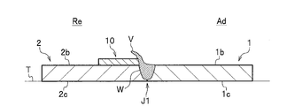
- the removal step is a step of removing the auxiliary member 10 from the second metal member 2 as shown in FIG.
- the auxiliary member 10 is bent away from the second metal member 2 and removed from the second metal member 2 by, for example, manual work. Thereby, as shown in FIG. 5, the 1st metal member 1 and the 2nd metal member 2 are joined planarly.
- the first metal member 1 and the second metal member 2 are joined, and in addition to the first metal member 1 and the second metal member 2, the auxiliary member 10 is also used.
- the auxiliary member 10 is also friction stir welded at the same time, so that even if a gap is generated in the butt portion J 1, the plastic fluidized metal is The gap can be filled, and metal shortage at the joint (plasticized region W) can be prevented.
- metal shortage can be prevented only by arrange
- the burrs V are formed in the auxiliary member 10 by the friction stirring process, but it can be removed together with the auxiliary member 10 in the removing process.
- flash can be performed easily.
- the end surface of the auxiliary member 10 is inclined so that the plate thickness becomes thinner as it goes to the abutting portion J1.
- the auxiliary member 10 may use a removing device or the like, in this embodiment, the auxiliary member 10 can be easily removed manually.
- the auxiliary member 10 is set to be thinner than the first metal member 1 and the second metal member 2, so that friction stir while pushing the shoulder portion into the metal member as in the past.
- the auxiliary member 10 is blown to the outside and the metal shortage at the joint portion cannot be compensated.
- the friction stir is performed while only the stirring pin F2 of the rotating tool F for welding is brought into contact with the first metal member 1, the second metal member 2, and the auxiliary member 10, the auxiliary member 10 is skipped to the outside. It is possible to make up for the metal shortage at the joint without being damaged.
- the load which acts on a friction stirrer can be reduced compared with the case where a shoulder part is made to contact.
- the auxiliary member 10 is disposed on the left side in the traveling direction and the welding rotary tool F is rotated counterclockwise, so the auxiliary member 10 side is on the Re side (retreating side). It becomes.
- the Re side is a side on which the magnitude of the feed speed is subtracted from the magnitude of the tangential speed on the outer periphery of the welding rotary tool F (also referred to as “flow side”).
- the side opposite to the Re side is the Ad side (advancing side).
- the Ad side is a side where the magnitude of the feed speed is added from the magnitude of the tangential speed on the outer periphery of the welding rotary tool F (also referred to as “shear side”).
- the temperature of the plastic fluidized material is more likely to rise on the Ad side than on the Re side of the plasticizing region W, so that more burrs V are generated on the Ad side. Tend to.
- the rotational speed of the bonding rotary tool F is high, the temperature of the plastic fluidized material increases on the Ad side, but there is a tendency that burrs V are generated on the Re side due to the higher rotational speed.
- the rotation speed of the welding rotary tool F is set to be high, burrs V are generated on the Re side, that is, on the auxiliary member 10 side. That is, in the present embodiment, the rotational speed, the rotational direction, the traveling direction, and the like of the bonding rotary tool F are set so that a large number of burrs V are formed on the auxiliary member 10 side. Thereby, since the burr
- the joining conditions include the rotational speed, rotational direction, moving direction, moving speed (feed speed) of the rotating tool F for joining, the inclination angle (taper angle) of the stirring pin F2, the first metal member 1, and the second metal member 2.
- the material of the auxiliary member 10 the thickness of each member, etc., and the combination of these elements. It is preferable to arrange the auxiliary member 10 on the side where burrs V are generated or on the side where many burrs V are generated, depending on the joining conditions, because the burr removing step can be easily performed.
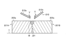
- the joining method according to the second embodiment is different from the first embodiment in that the auxiliary member 10 is disposed so as to be in contact with both the first metal member 1 and the second metal member 2 as shown in FIG. .
- the joining method according to the second embodiment will be described with a focus on the differences from the first embodiment.
- the joining method according to the present embodiment performs a butt process, an arrangement process, a friction stirring process, and a removal process. Since the matching process is the same as that of the first embodiment, description thereof is omitted.
- the arranging step is a step of arranging the auxiliary member 10 on both the first metal member 1 and the second metal member 2.
- the placement step is a step of bringing the front surface 1b of the first metal member 1 and the front surface 2b of the second metal member 2 into contact with the back surface 10c of the auxiliary member 10 as shown in FIG.
- board thickness of the auxiliary member 10 is suitably set so that the plasticization area
- the auxiliary member 10 is arranged so that the center of the auxiliary member 10 is positioned approximately at the butting portion J1. Moreover, the 1st metal member 1, the 2nd metal member 2, and the auxiliary member 10 are restrained immovably using a jig
- the friction stirring step is a step of joining the butted portion J1 of the first metal member 1 and the second metal member 2 by friction stirring using the rotating tool F for joining.
- the spiral groove of the stirring pin F2 is formed in a counterclockwise direction from the proximal end toward the distal end.
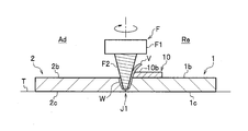
- the stirring pin F2 rotated clockwise is inserted from the surface 10b of the auxiliary member 10, and the insertion depth of the stirring pin F2 is set so as to reach the abutting portion J1.
- the friction stirring step only the stirring pin F2 rotated to the right is inserted into the abutting portion J1, and the bonded metal member and the connecting portion F1 are moved while being separated from each other.
- the friction stir welding is performed with the base end portion of the stirring pin F2 exposed.
- the joining rotary tool F is directed from the near side to the far side in FIG. To move relative.
- the butt J1 is friction stir welded.
- a plasticized region W is formed on the movement locus of the welding rotary tool F.
- burrs tend to occur more on the Re side than on the Ad side.
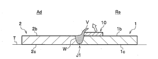
- the removing step is a step of removing the auxiliary member 10 separated by the friction stirring step from the first metal member 1 and the second metal member 2 as shown in FIG.
- the auxiliary members 10 and 10 are bent and removed in directions away from the first metal member 1 and the second metal member 2, respectively.
- the first metal member 1 and the second metal member 2 are joined in a planar shape, and in addition to the first metal member 1 and the second metal member 2, the auxiliary By simultaneously performing friction stir welding on the member 10 as well, it is possible to prevent metal shortage at the joint (plasticization region W). Further, in addition to the first metal member 1 and the second metal member 2, the auxiliary member 10 is also friction stir welded at the same time, so that even if a gap is generated in the butt portion J 1, the plastic fluidized metal is The gap can be filled, and metal shortage at the joint (plasticized region W) can be prevented. In addition, since the auxiliary member 10 is disposed so as to straddle both the first metal member 1 and the second metal member 2, it is possible to more reliably prevent metal shortage at the joint portion and to replenish metal in a balanced manner. it can.
- the burrs V and V are formed on the auxiliary members 10 and 10 separated by the friction stirring process, respectively, but the auxiliary member 10 can be removed together in the removing process.
- flash can be performed easily.
- the auxiliary member 10 may use a removing device or the like, in this embodiment, the auxiliary member 10 can be easily removed manually.
- the joining method according to the third embodiment of the present invention will be described.
- the first metal member with respect to the auxiliary member 10 while the auxiliary member 10 is arranged on both the first metal member 1 and the second metal member 2 in the arranging step. It differs from the first embodiment in that the contact ratio between 1 and the second metal member 2 is changed. Further, the rotating direction of the joining rotary tool F is also different from that of the first embodiment.
- the joining method according to the third embodiment will be described with a focus on differences from the first embodiment.
- the joining method which concerns on 3rd embodiment performs a butt
- the arranging step is a step of bringing the surface 1 b of the first metal member 1 and the surface 2 b of the second metal member 2 into contact with the back surface 10 c of the auxiliary member 10.
- the placement step about 90% of the auxiliary member 10 is placed on the first metal member 1 and the remaining 10% is placed on the second metal member 2. That is, the auxiliary member 10 is disposed so as to slightly protrude toward the second metal member 2 with respect to the abutting portion J1.
- the auxiliary member 10 is disposed such that the auxiliary member 10 is in surface contact with both the first metal member 1 and the second metal member 2, and the second metal member 2 side after the friction stirring step described later is performed. Adjustment is made so that the auxiliary member 10 does not remain on the side where the contact ratio with the auxiliary member 10 is small.
- the friction stirring step is a step of joining the butted portion J1 between the first metal member 1 and the second metal member 2 by friction stirring using the rotating tool F for bonding.
- the spiral groove of the stirring pin F2 is formed in a counterclockwise direction from the proximal end toward the distal end.
- the removal step is a step of removing the auxiliary member 10 from the first metal member 1 as shown in FIG.
- the auxiliary member 10 is bent and removed from the first metal member 1 by manual work, for example, in a direction away from the first metal member 1.
- the first metal member 1 and the second metal member 2 are joined in a planar shape, and in addition to the first metal member 1 and the second metal member 2, the auxiliary By simultaneously performing friction stir welding on the member 10 as well, it is possible to prevent metal shortage at the joint (plasticization region W). Further, in addition to the first metal member 1 and the second metal member 2, the auxiliary member 10 is also friction stir welded at the same time, so that even if a gap is generated in the butt portion J 1, the plastic fluidized metal is The gap can be filled, and metal shortage at the joint (plasticized region W) can be prevented.
- the rotational speed of the joining rotary tool F is set to be high, there is a tendency that many burrs V are generated on the Re side. That is, in this embodiment, the rotation direction, the traveling direction, and the like (joining conditions) of the joining rotary tool F are set so that many burrs V are formed on the first metal member 1 side of the auxiliary member 10. Thereby, since the burr
- the arrangement position of the auxiliary member 10 is adjusted so that the auxiliary member 10 does not remain on the second metal member 2 side (side where the contact ratio with the auxiliary member 10 is small) after the friction stirring step.
- the removing step it is only necessary to remove the auxiliary member 10 on one side. This can reduce the labor of the removal process.
- the metal shortage of the joining portion can be prevented in a balanced and more reliable manner by the amount of the auxiliary member 10 slightly projecting to the second metal member 2 side (the other side) with the butting portion J1 interposed therebetween. it can.
- the auxiliary member 10 may be left as it is in the first metal member 1 or the second metal member 2 without being removed.
- a joining method according to a fourth embodiment of the present invention will be described in detail with reference to the drawings.
- a preparation process, a butting process, an arranging process, a friction stirring process, and a removing process are performed.
- the preparation step is a step of preparing the first metal member 1 and the second metal member 2 as shown in FIG.
- the first metal member 1 and the second metal member 2 have a plate shape.
- the first metal member 1 is thicker than the second metal member 2.
- the material of the first metal member 1 and the second metal member 2 is not particularly limited as long as it is a metal that can be frictionally stirred.
- aluminum, aluminum alloy, copper, copper alloy, titanium, titanium alloy, magnesium, magnesium alloy, etc. May be selected as appropriate.
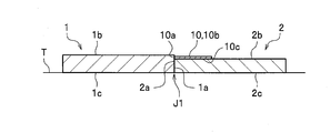
- the butting step is a step of matching the first metal member 1 and the second metal member 2 as shown in FIG.
- the end surface 1a of the first metal member 1 and the end surface 2a of the second metal member 2 are butted to form a butting portion J1.
- a first step is formed on the surface 1 b, the end surface 1 a of the first metal member 1, and the surface 2 b of the second metal member 2.
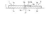
- the placement step is a step of placing the auxiliary member 10 at the first step as shown in FIG.
- the auxiliary member 10 is a metal plate member.
- the auxiliary member 10 is not particularly limited as long as it is a metal capable of friction stirring, but in the present embodiment, the auxiliary member 10 is made of the same material as the first metal member 1 and the second metal member 2.
- the thickness of the auxiliary member 10 is equal to the height of the first step (height from the surface 2b to the surface 1b). Therefore, the surface 1b of the first metal member 1 and the surface 10b of the auxiliary member 10 are flush with each other.
- the height of the first step (the thickness of the auxiliary member 10) is appropriately set to such an extent that the plasticized region W after the friction stirring step described later does not run out of metal.
- the end surface 10a of the auxiliary member 10 and the end surface 1a of the first metal member 1 are brought into surface contact while the back surface 10c of the auxiliary member 10 and the surface 2b of the second metal member 2 are brought into surface contact.
- the 1st metal member 1, the 2nd metal member 2, and the auxiliary member 10 are restrained to the mount frame T so that a movement is impossible using a jig
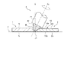
- the friction stirring step is a step of joining the butted portion J1 between the first metal member 1 and the second metal member 2 by friction stirring using the welding rotary tool F as shown in FIG.
- the joining rotary tool F includes a connecting portion F1 and a stirring pin F2.
- the spiral groove is formed in a counterclockwise direction from the base end toward the tip end in order to rotate the joining rotary tool F to the right.
- the spiral groove is formed counterclockwise as viewed from above when the spiral groove is traced from the proximal end to the distal end.
- the plastic fluidized metal during frictional stirring is guided to the tip side of the stirring pin F2 by the spiral groove.
- the quantity of the metal which overflows outside the to-be-joined metal member (the 1st metal member 1, the 2nd metal member 2, and the auxiliary member 10) can be decreased.
- the spiral groove may be omitted.
- the rotating tool F for joining may be attached to a friction stirrer such as a machining center, but may be attached to an arm robot having a rotating means such as a spindle unit at the tip, for example.
- a friction stirrer such as a machining center
- an arm robot having a rotating means such as a spindle unit at the tip, for example.
- the traveling direction of the welding rotary tool F is set so that the auxiliary member 10 is positioned on the right side of the traveling direction of the welding rotary tool F.
- the rotation direction and the traveling direction of the joining rotary tool F are not limited to those described above, and may be set as appropriate.
- the joining rotary tool F may be rotated counterclockwise while the auxiliary member 10 is disposed on the right side in the traveling direction of the joining rotary tool F.
- the auxiliary member 10 may be arranged while forming a first step on the left side in the traveling direction of the joining rotary tool F, and the joining rotary tool F may be rotated to the left or right.
- the preferable positional relationship between the auxiliary member 10 and the conditions such as the rotation direction of the joining rotary tool F will be described later.
- the removal step is a step of removing the auxiliary member 10 from the second metal member 2 as shown in FIG.
- the auxiliary member 10 is bent from the second metal member 2 in a direction away from the second metal member 2 and removed from the second metal member 2 by manual work.
- the first metal member 1 and the second metal member 2 are joined, and in addition to the first metal member 1 and the second metal member 2, the auxiliary member 10 is also used.
- the auxiliary member 10 is also used.
- the burrs V are formed in the auxiliary member 10 by the friction stirring process, but it can be removed together with the auxiliary member 10 in the removing process.
- flash V can be performed easily.
- the auxiliary member 10 may use a removing device or the like, in this embodiment, the auxiliary member 10 can be easily removed manually.
- board thickness of the 1st metal member 1 and the 2nd metal member 2 differs, since the auxiliary member 10 is used, the metal shortage of a junction part can be prevented.
- the joining rotary tool F can be easily inserted during the friction stirring step. .
- the auxiliary member 10 is set thinner than the first metal member 1 and the second metal member 2, the shoulder portion of the rotary tool is pushed into the metal member as in the past.
- the auxiliary member 10 is blown to the outside due to the contact between the shoulder portion and the auxiliary member 10, and the metal shortage at the joint portion cannot be compensated.
- the friction stir is performed while only the stirring pin F2 of the rotating tool F for welding is brought into contact with the first metal member 1, the second metal member 2, and the auxiliary member 10, the auxiliary member 10 is skipped to the outside. It is possible to make up for the metal shortage at the joint without being damaged.
- the load which acts on a friction stirrer can be reduced compared with the case where the shoulder part of a rotary tool is made to contact.
- the auxiliary member 10 is disposed on the right side in the traveling direction and the welding rotary tool F is rotated to the right, so the auxiliary member 10 side is the Re side.
- the rotation speed of the welding rotary tool F is set to be high, burrs V are generated on the Re side, that is, on the auxiliary member 10 side. That is, in this embodiment, the joining conditions are set so that a large number of burrs V are formed on the auxiliary member 10 side. Thereby, since the burr
- the auxiliary member 10 on the side where burrs V are generated or on the side where many burrs V are generated, depending on the joining conditions, because the burr removing step can be easily performed.
- the first modification example differs from the fourth embodiment in that a step is generated between the first metal member 1 and the auxiliary member 10. That is, since the plate thickness of the auxiliary member 10 is set to be thinner than the height of the first step, the surface 10b of the auxiliary member 10 is located at a position lower than the surface 1b of the first metal member 1. . Thereby, the 2nd level
- the auxiliary member 10 since the auxiliary member 10 is set thinner than the height of the first step, the auxiliary member 10 is easily broken. Thereby, the auxiliary member 10 can be easily removed in the removing step.
- the second modification example differs from the fourth embodiment in that a step is generated between the first metal member 1 and the auxiliary member 10. That is, since the plate thickness of the auxiliary member 10 is set to be thicker than the height of the first step, the surface 10b of the auxiliary member 10 is positioned higher than the surface 1b of the first metal member 1. . Thereby, the 2nd level
- the auxiliary member 10 is set thicker than the height of the first step. Therefore, in a friction stirring process, since the auxiliary member 10 is friction-stirred more than 4th embodiment, metal shortage can be prevented more reliably.
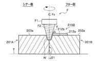
- the joining method according to the fifth embodiment is mainly different in that the rotation center axis Fc of the joining rotary tool F is shifted to the center side of the auxiliary member 10 from the abutting portion J1. To do.
- a preparation process, a butting process, an arranging process, a friction stirring process, and a removing process are performed. Since the preparation process, the matching process, and the arrangement process according to the fifth embodiment are substantially the same as those of the fourth embodiment, the description thereof is omitted.
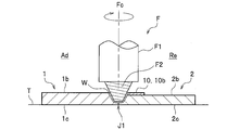
- the abutting portion J1 is friction stir welded using the welding rotary tool F.
- the joining rotary tool F is rotated counterclockwise while the auxiliary member 10 is disposed on the left side in the traveling direction of the joining rotary tool F.
- the right side in the traveling direction is the Ad side
- the left side is the Re side.
- the rotation center axis Fc of the welding rotary tool F is shifted so as to be located closer to the center side of the auxiliary member 10 than the abutting portion J1 (boundary line C).
- the welding rotary tool F is relatively moved in parallel with the abutting portion J1.
- the auxiliary member 10 is bent at the concave groove P in the same manner as in the fourth embodiment, and the auxiliary member 10 is removed together with the burr V.
- friction agitation is performed in a state where the rotation center axis Fc of the rotating tool F for welding is shifted, so that the auxiliary member 10 is more frictioned than in the fourth embodiment. Can be stirred. Thereby, the metal shortage of a junction part (plasticization area
- the first metal member 1 and the second metal member 2 are set to have different plate thicknesses, but may have the same plate thickness.
- the butted portion J1 may be formed by shifting the end surfaces of the first metal member 1 and the second metal member 2 having the same plate thickness so as to make a step difference.
- the friction stir welding may be performed in a state where the welding rotary tool F is shifted from the abutting portion J1 (boundary line C) as in the fifth embodiment.
- the polymerization step is a step of overlapping the first metal member 1 and the second metal member 2 as shown in FIG.
- the first metal member 1 and the second metal member 2 are metal plate-like members.
- board thickness of the 1st metal member 1 and the 2nd metal member 2 is equivalent.
- the plate thicknesses of the first metal member 1 and the second metal member 2 may be set as appropriate.
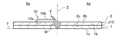
- the superposed portion J10 is formed by overlapping the front surface 1b of the first metal member 1 and the back surface 2c of the second metal member 2.
- the placement step is a step of placing the auxiliary member 10 on the second metal member 2.
- the auxiliary member 10 is a metal plate member.
- the auxiliary member 10 is not particularly limited as long as it is a metal capable of friction stirring, but in the present embodiment, the auxiliary member 10 is made of the same material as the first metal member 1 and the second metal member 2.
- board thickness of the auxiliary member 10 is suitably set so that the plasticization area
- the back surface 10c of the auxiliary member 10 and the front surface 2b of the second metal member 2 are brought into surface contact.
- the 1st metal member 1, the 2nd metal member 2, and the auxiliary member 10 are restrained to the mount frame T so that a movement is impossible using a jig
- the auxiliary member 10 is plate-shaped in this embodiment, another shape may be sufficient.
- the friction stir step is a step of joining the overlapping portion J10 of the first metal member 1 and the second metal member 2 by friction stir using the joining rotary tool F as shown in FIG.
- the joining rotary tool F includes a connecting portion F1 and a stirring pin F2.
- the joining rotary tool F corresponds to a “rotary tool” in the claims.
- the spiral groove is formed clockwise as it goes from the proximal end to the distal end in order to rotate the joining rotary tool F counterclockwise. In other words, when the spiral groove is traced from the proximal end to the distal end, the spiral groove is formed clockwise when viewed from above.
- the spiral groove may be omitted.
- a line passing through the end surface 10 a of the auxiliary member 10 and orthogonal to the first metal member 1 and the second metal member 2 is defined as a reference line Z.
- the first metal member 1, the second metal member 2, the auxiliary member 10, and the agitation pin F2 are brought into contact with each other in a state where the rotation center axis Fc of the rotating tool F for welding is superimposed on the reference line Z. In this state, the rotating tool F for bonding is relatively moved.
- the traveling direction of the joining rotary tool F is set so that the auxiliary member 10 is located on the left side in the traveling direction of the joining rotary tool F.
- the rotation direction and the traveling direction of the joining rotary tool F are not limited to those described above, and may be set as appropriate.
- the joining rotary tool F may be rotated to the right while the auxiliary member 10 is disposed on the left side in the traveling direction of the joining rotary tool F.
- the joining rotary tool F may be rotated to the left or right while the auxiliary member 10 is disposed on the right side in the traveling direction of the joining rotary tool F.
- the conditions such as the rotation direction of the bonding rotary tool F and the preferred positional relationship of the auxiliary member 10 will be described later.
- the insertion depth of the stirring pin F2 is set so that the stirring pin F2 reaches the first metal member 1 in this embodiment.
- a plasticized region W is formed on the movement locus of the welding rotary tool F. After the friction stirring step, burrs V are formed at the end of the auxiliary member 10 as shown in FIG.
- the removal step is a step of removing the auxiliary member 10 from the second metal member 2 as shown in FIGS.
- the auxiliary member 10 is bent away from the second metal member 2 and removed from the second metal member 2 by, for example, manual work. Thereby, as shown in FIG. 25, the 1st metal member 1 and the 2nd metal member 2 are joined to a plate
- the first metal member 1 and the second metal member 2 are joined, and in addition to the first metal member 1 and the second metal member 2, the auxiliary member 10 is also used.
- the auxiliary member 10 is also used.
- the burrs V are formed in the auxiliary member 10 by the friction stirring process, but it can be removed together with the auxiliary member 10 in the removing process.
- flash can be performed easily.
- the end surface of the auxiliary member 10 is inclined so that the plate thickness becomes thinner toward the center of the plasticizing region W.
- the auxiliary member 10 may use a removing device or the like, in this embodiment, the auxiliary member 10 can be easily removed manually.
- the auxiliary member 10 is set thinner than the first metal member 1 and the second metal member 2, the shoulder portion of the rotary tool is pushed into the metal member as in the past.
- the auxiliary member 10 is blown to the outside due to the contact between the shoulder portion and the auxiliary member 10, and the metal shortage at the joint portion cannot be compensated.
- the friction stir is performed while only the stirring pin F2 of the rotating tool F for welding is brought into contact with the first metal member 1, the second metal member 2, and the auxiliary member 10, the auxiliary member 10 is skipped to the outside. It is possible to make up for the metal shortage at the joint without being damaged.
- the load which acts on a friction stirrer can be reduced compared with the case where the shoulder part of a rotary tool is made to contact.
- the auxiliary member 10 is disposed on the left side in the traveling direction and the rotating tool F for welding is rotated counterclockwise, so the auxiliary member 10 side is the Re side.
- the rotation speed of the welding rotary tool F is set to be high, burrs V are generated on the Re side, that is, on the auxiliary member 10 side. That is, in this embodiment, the joining conditions of the joining rotary tool F are set so that a large number of burrs V are formed on the auxiliary member 10 side. Thereby, since the burr
- the auxiliary member 10 on the side where burrs V are generated or on the side where many burrs V are generated, depending on the joining conditions, because the burr removing step can be easily performed.
- the joining method according to the seventh embodiment is different from the sixth embodiment in that the joining rotary tool F is inserted from the central portion of the auxiliary member 10.
- the joining method according to the seventh embodiment will be described with a focus on the differences from the sixth embodiment.
- the joining method according to this embodiment includes a polymerization process, an arrangement process, a friction stirring process, and a removal process. Since the polymerization process is the same as in the sixth embodiment, a description thereof will be omitted.
- the placement step is a step of placing the auxiliary member 10 on the surface 2 b of the second metal member 2.
- the back surface 10c of the auxiliary member 10 is brought into surface contact with the front surface 2b of the second metal member 2 as shown in FIG.
- board thickness of the auxiliary member 10 is suitably set so that the plasticization area
- the 1st metal member 1, the 2nd metal member 2, and the auxiliary member 10 are restrained immovably using a jig
- the friction stirring step is a step of joining the overlapping portion J10 of the first metal member 1 and the second metal member 2 by friction stirring using the rotating tool F for bonding as shown in FIG.
- the stirring pin F2 rotated to the right is inserted from the center of the surface 10b of the auxiliary member 10, and the insertion depth of the stirring pin F2 is set so as to reach the first metal member 1.
- the friction stirring step only the stirring pin F2 rotated to the right is inserted into the overlapping portion J10, and the bonded metal member and the connecting portion F1 are moved while being separated from each other. In other words, the friction stir welding is performed with the base end portion of the stirring pin F2 exposed.
- the spiral groove of the stirring pin F2 is formed in a counterclockwise direction from the proximal end toward the distal end.
- the joining rotary tool F is relatively moved along the overlapping portion J10 in a state where the first metal member 1, the second metal member 2, the auxiliary member 10 and the stirring pin F2 are in contact with each other.
- the overlapping portion J10 is friction stir welded.
- a plasticized region W is formed on the movement locus of the welding rotary tool F.
- friction stirring may be performed by bringing the stirring pin F2 into contact with only the second metal member 2 and the auxiliary member 10 (so as not to reach the first metal member 1).
- the removal step is a step of removing the auxiliary member 10 separated by the friction stirring step from the first metal member 1 and the second metal member 2 as shown in FIG.
- the auxiliary members 10 and 10 are bent and removed in a direction away from the second metal member 2.
- the first metal member 1 and the second metal member 2 are joined, and in addition to the first metal member 1 and the second metal member 2, the auxiliary member 10 is also used.
- the auxiliary member 10 is also used.
- the burrs V and V are formed on the auxiliary members 10 and 10 separated by the friction stirring process, respectively, but the auxiliary member 10 can be removed together in the removing process.
- flash can be performed easily.
- the auxiliary member 10 may use a removing device or the like, in this embodiment, the auxiliary member 10 can be easily removed manually.
- the joining method according to the eighth embodiment of the present invention will be described. As shown in FIGS. 29 and 30, in the joining method according to the eighth embodiment, the insertion position of the stirring pin F2 is mainly different from that of the sixth embodiment. The joining method according to the eighth embodiment will be described with a focus on differences from the sixth embodiment. The joining method according to the eighth embodiment performs a polymerization process, an arrangement process, a friction stirring process, and a removal process.
- positioning process is a process which surface-contacts the surface 2b of the 2nd metal member 2, and the back surface 10c of the auxiliary member 10 as shown in FIG.
- the auxiliary member 10 is arranged so that the auxiliary member 10 is located on the right side in the traveling direction of the welding rotary tool F.
- the friction stir step is a step of joining the overlapping portion J10 of the first metal member 1 and the second metal member 2 by friction stir using the rotating tool F for joining as shown in FIG.
- the spiral groove of the stirring pin F2 is formed in a counterclockwise direction from the proximal end toward the distal end.
- the traveling direction of the joining rotary tool F is set so that the auxiliary member 10 is positioned on the right side in the traveling direction of the joining rotary tool F, and is rotated at a high speed. Thereby, in this embodiment, the auxiliary member 10 side becomes the Re side, and many burrs V are generated in the auxiliary member 10.
- the insertion position of the welding rotary tool F in this embodiment (the distance between the rotation center axis Fc of the welding rotary tool F and the reference line Z) is assisted only on one side of the welding rotary tool F after the friction stirring step. It adjusts suitably to such an extent that member 10 remains.
- the removing step is a step of removing the auxiliary member 10 from the second metal member 2 as shown in FIG.
- the auxiliary member 10 is bent away from the second metal member 2 and removed from the second metal member 2 by, for example, manual work.
- the first metal member 1 and the second metal member 2 are joined, and in addition to the first metal member 1 and the second metal member 2, the auxiliary member 10 is also used.
- the auxiliary member 10 is also used.
- the rotational speed of the joining rotary tool F is set to be high, there is a tendency that many burrs V are generated on the Re side. That is, in the present embodiment, the rotation direction and the traveling direction (bonding conditions) of the bonding rotary tool F are set so that a large number of burrs V are formed on the auxiliary member 10. Thereby, since the burr
- the position of the auxiliary member 10 is adjusted so that the auxiliary member 10 does not remain on one side (the left side in the direction of travel of the bonding rotary tool F) after the friction stirring step. It is only necessary to remove the auxiliary member 10 remaining on the surface. This can reduce the labor of the removal process.
- the rotation center axis Fc is slightly shifted to the center side of the auxiliary member 10 from the reference line Z, it is possible to prevent the metal shortage of the joint portion in a balanced manner and more reliably. Further, since the rotation center axis Fc is slightly shifted to the center side of the auxiliary member 10 with respect to the reference line Z, the stirring pin F2 can be easily inserted into the auxiliary member 10.
- auxiliary member 10 may be left as it is without removing the auxiliary member 10.
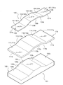
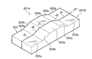
- the first metal member 101 and the second metal member 110 which are a step of overlapping the first metal member 101 and the second metal member 110, are metal plate-like members.
- the material of the first metal member 101 and the second metal member 110 is not particularly limited as long as it is a metal capable of friction stir.
- aluminum, aluminum alloy, copper, copper alloy, titanium, titanium alloy, magnesium, magnesium alloy, etc. May be selected as appropriate.
- the plate thickness of the first metal member 101 is thicker than the plate thickness of the second metal member 110.
- the first metal member 101 is composed of a main body portion 102 that has a rectangular parallelepiped shape and a convex portion 103 that is formed on the main body portion 102 and has a trapezoidal cross section.
- the surface 103 a of the convex portion 103 is located above the surfaces 102 a and 102 b of the main body portion 102.
- the first surface 103 b of the convex part 103 is inclined and connects the surface 102 a of the main body part 102 and the surface 103 a of the convex part 103.
- the second surface 103 c of the convex portion 103 is inclined and connects the surface 102 b of the main body portion 102 and the surface 103 a of the convex portion 103.
- the second metal member 110 is a plate-like member having a different height, which is thinner than the first metal member 101 and formed with a constant plate thickness.
- the second metal member 110 includes base portions 111 and 111, a central portion 112, and inclined portions 113 and 114.
- the central portion 112 is formed at a position higher than the base portions 111 and 111 in the center of the base portions 111 and 111.
- the inclined portion 113 connects one base portion 111 and the central portion 112 obliquely.
- the inclined portion 114 obliquely connects the other base 111 and the central portion 112.
- the back surface of the second metal member 110 is overlapped on the surface of the first metal member 101 to form a polymerization portion J11. More specifically, the front surfaces 102a and 102b of the main body 102 and the back surfaces 111b and 111b of the base portions 111 and 111 are overlapped, and the front surface 103a of the convex portion 103 and the back surface 112b of the central portion 112 are overlapped. Further, the first surface 103b of the convex portion 103 and the back surface 113b of the inclined portion 113 are overlapped, and the second surface 103c of the convex portion 103 and the back surface 114b of the inclined portion 114 are overlapped.
- the first metal member 101 and the second metal member 110 are overlapped with almost no gap.
- the overlapping portion J11 is formed such that its height position changes. That is, in the overlapping portion J11, when the height (elevation) of the starting point (insertion position) of friction stirring is set as the reference height, there are sections having different reference heights and heights from the starting point to the end point.
- the overlapping portion J11 includes a first flat portion Ja, a first inclined portion Jb, a second flat portion Jc, a second inclined portion Jd, and a third flat portion Je.
- the placement step is a step of placing the auxiliary member 120 on the second metal member 110 shown in FIG.
- the auxiliary member 120 is a metal plate member.
- the auxiliary member 120 is not particularly limited as long as it is a metal capable of friction stirring, but in the present embodiment, the auxiliary member 120 is made of the same material as the first metal member 101 and the second metal member 110.
- board thickness of the auxiliary member 120 is suitably set so that the plasticization area
- the auxiliary member 120 is a plate-like member having a different thickness and formed with a constant plate thickness.
- the auxiliary member 120 includes base parts 121 and 121, a central part 122, and inclined parts 123 and 124.
- the central portion 122 is formed at a position higher than the base portions 121 and 121 in the center of the base portions 121 and 121.
- the inclined portion 123 obliquely connects one base 121 and the central portion 122.
- the inclined portion 124 obliquely connects the other base portion 121 and the central portion 122.
- slits 125 and 125 are provided in the vicinity of the center of the respective end portions of the base portions 121 and 121.
- the back surface of the auxiliary member 120 is brought into surface contact along the central portion of the front surface of the second metal member 110 in the longitudinal direction. More specifically, as shown in FIG. 33, the front surfaces 111a and 111a of the base portions 111 and 111 of the second metal member 110 and the back surfaces 121b and 121b of the base portions 121 and 121 of the auxiliary member 120 are overlapped with each other, and the central portion 112 The front surface 112a and the back surface 122b of the central portion 122 are overlapped. Further, the first surface 113a of the inclined portion 113 and the back surface 123b of the inclined portion 123 are overlapped, and the second surface 114a of the inclined portion 114 and the back surface 124b of the inclined portion 124 are overlapped.
- the first metal member 101, the second metal member 110, and the auxiliary member 120 are restrained on the gantry T so as not to move using a jig (not shown).
- the auxiliary member 120 has a plate shape with a different height in this embodiment, but may have another shape.
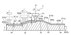
- the friction stirring step is a step of joining the overlapping portion J11 of the first metal member 101 and the second metal member 110 by friction stirring using the rotating tool F for bonding.
- the joining rotary tool F includes a connecting portion F1 and a stirring pin F2.
- the joining rotary tool F corresponds to a “rotary tool” in the claims.
- the spiral groove is formed in a counterclockwise direction from the proximal end toward the distal end in order to rotate the joining rotary tool F to the right. In other words, the spiral groove is formed counterclockwise as viewed from above when the spiral groove is traced from the proximal end to the distal end.
- the plastic fluidized metal during frictional stirring is guided to the tip side of the stirring pin F2 by the spiral groove.
- the quantity of the metal which overflows outside the to-be-joined metal member (the 1st metal member 101, the 2nd metal member 110, and the auxiliary member 120) can be decreased.
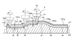
- the stirring pin F2 of the welding rotary tool F rotated to the right is inserted to the overlapping portion J11 as shown in FIG. 35 at the start position Sp set on the surface of the auxiliary member 120 shown in FIG.
- the insertion depth of the stirring pin F ⁇ b> 2 is set so that the stirring pin F ⁇ b> 2 reaches the first metal member 101.
- the friction stir is performed in a state where the rotation center axis of the welding rotary tool F is always parallel to the vertical axis.
- the overlapping portion J11 may be frictionally stirred with the stirring pin F2 in contact with only the second metal member 110 and the auxiliary member 120.
- the overlapping portion J11 is plastically fluidized and joined by frictional heat between the stirring pin F2, the second metal member 110, and the auxiliary member 120.
- a plasticized region W is formed in the auxiliary member 120 in the movement locus of the welding rotary tool F.
- Friction stirring is performed in a state where the member 110 is in contact with the member 110.
- the rotating tool F for joining is placed above and below the auxiliary member 120 with respect to a gantry (not shown) to which the auxiliary member 120, the first metal member 101, and the second metal member 110 are fixed. Friction stirring is performed by moving up and down surfaces with different heights (elevations).
- the “insertion depth” of the stirring pin F2 means the distance from the surface of the auxiliary member 120 to the tip of the stirring pin F2 on the rotation center axis Fc of the rotating tool F for joining.
- the periphery of the agitation pin F2 is frictionally agitated by the friction agitation process, and the first metal member 101 and the second metal member 110 are joined. At this time, as shown in FIGS. 36 and 37, burrs V are formed on the surface portion of the auxiliary member 120.
- the stirring pin F2 may be brought into contact with only the second metal member 110 and the auxiliary member 120 (not reaching the first metal member 101) for friction stirring. In this case, the overlapping portion J11 is plastically fluidized and joined by frictional heat between the stirring pin F2, the second metal member 110, and the auxiliary member 120.
- the removing step is a step of removing the auxiliary member 120 from the second metal member 110 as shown in FIGS. 38 and 39.
- the auxiliary member 120 is bent from both sides in a direction away from the second metal member 110 by, for example, manual work and removed from the second metal member 110.
- the auxiliary member 120 is removed by bending while turning up one end of one of the slits 125, 125 (see FIG. 34).
- the first metal member 101 and the second metal member 110 are joined, and in addition to the first metal member 101 and the second metal member 110, the auxiliary member 120 is also used.
- the auxiliary member 120 is also used.
- the stirring pin F2 by inserting the stirring pin F2 from the central portion of the auxiliary member 120, it is possible to more reliably prevent metal shortage at the joint portion and to replenish metal in a well-balanced manner. Further, by inserting the stirring pin F2 from the central portion of the auxiliary member 120, the stirring pin F2 can be easily inserted into the auxiliary member 120.
- the burrs V and V are formed on the auxiliary members 120 and 120 separated by the friction stirring process, respectively, but can be removed together with the auxiliary members 120 and 120 in the removing process.
- flash can be performed easily.
- the auxiliary member 120 may be removed using a removing device or the like, but in the present embodiment, the auxiliary member 120 can be easily removed manually.
- the auxiliary member 120 is set thinner than the first metal member 101 and the second metal member 110, the shoulder portion of the rotary tool is pushed into the metal member as in the past.
- the auxiliary member 120 is blown to the outside due to the contact between the shoulder portion and the auxiliary member 120, and the metal shortage at the joint portion cannot be compensated.
- the friction stir is performed while only the stirring pin F2 of the rotating tool F for welding is in contact with the first metal member 101, the second metal member 110, and the auxiliary member 120, the auxiliary member 120 is skipped to the outside. It is possible to make up for the metal shortage at the joint without being damaged.
- polymerization part J11 in a deep position can be joined in the state which reduced the load which acts on a friction stirrer compared with the case where the shoulder part of a rotary tool is made to contact.
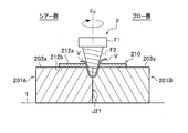
- FIG. 40 is a cross-sectional view showing a friction stirring step of a modification of the joining method according to the ninth embodiment.
- the friction stirring is performed while inserting the welding rotary tool F perpendicularly to the joining surface.
- the rotation center axis Fc of the welding rotary tool F is parallel to the vertical axis as in the ninth embodiment.
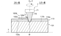
- the joining method according to the tenth embodiment is different from the ninth embodiment in that the joining rotary tool F is inserted from the end face 120a of the auxiliary member 120A shown in FIG. Further, the auxiliary member 120A is different in that slits 125, 125 are not formed.
- the joining method according to the tenth embodiment will be described with a focus on the differences from the ninth embodiment.
- the joining method according to this embodiment includes a polymerization process, an arrangement process, a friction stirring process, and a removal process. Since the polymerization process is the same as in the ninth embodiment, description thereof is omitted.
- the auxiliary member 120A is arranged on the surface of the second metal member 110 in the same manner as in the ninth embodiment.
- the auxiliary member 120A of the tenth embodiment is about half the width of the auxiliary member 120 of the ninth embodiment.
- the friction stirring step is a step of joining the overlapping portion J11 of the first metal member 101 and the second metal member 110 by friction stirring using the welding rotary tool F.
- the spiral groove of the stirring pin F2 is formed in a clockwise direction from the proximal end toward the distal end. In other words, when the spiral groove is traced from the proximal end to the distal end, the spiral groove is formed clockwise when viewed from above.
- the friction stirring step only the stirring pin F2 rotated counterclockwise is inserted, and the metal member to be joined and the connecting portion F1 are moved relative to each other while being separated. In other words, the friction stir welding is performed with the base end portion of the stirring pin F2 exposed.
- a line passing through the end surface 120a of the auxiliary member 120A and orthogonal to the first metal member 101 and the second metal member 110 is defined as a reference line Z.
- the first metal member 101, the second metal member 110, and the auxiliary member 120A are in a state where the rotation center axis Fc of the rotation tool F for welding is superimposed on the reference line Z.
- the joining rotary tool F is relatively moved in a state where the stirring pin F2 is in contact with the stirring pin F2.
- the joining rotary tool F is set so that the shear side (advancing side) is the right side in the traveling direction.
- the direction of movement and the direction of rotation are set.
- the rotation direction and the traveling direction of the joining rotary tool F are not limited to those described above, and may be set as appropriate.
- the rotational speed of the joining rotary tool F is set high, as shown in FIG. 43, many burrs V tend to occur on the flow side (Re side) outside the plasticizing region W. .
- the moving speed (feeding speed) of the joining rotary tool F can be increased by setting the rotational speed of the joining rotary tool F faster. Thereby, a joining cycle can be shortened.
- the insertion depth of the stirring pin F2 is set so that the stirring pin F2 reaches the first metal member 101 in this embodiment.
- the overlapping portion J11 is plastically fluidized and joined by frictional heat between the stirring pin F2, the second metal member 110, and the auxiliary member 120A.
- a plasticized region W is formed on the movement locus of the welding rotary tool F.
- the removing step is a step of removing the auxiliary member 120A from the second metal member 110 as shown in FIG.
- the auxiliary member 120A is bent away from the second metal member 110 by a manual operation, for example, as indicated by an arrow, and removed from the second metal member 110. Thereby, the first metal member 101 and the second metal member 110 are joined in the plate thickness direction.
- the first metal member 101 and the second metal member 110 are joined, and in addition to the first metal member 101 and the second metal member 110, the auxiliary member 120A is also used.
- the auxiliary member 120A is also used.
- the burr V is formed on the auxiliary member 120A by the friction stirring process, but it can be removed together with the auxiliary member 120A in the removing process.
- flash V can be performed easily.
- the auxiliary member 120A may be removed using a removing device or the like, but in the present embodiment, the auxiliary member 120A can be easily removed manually in the direction indicated by the arrow.
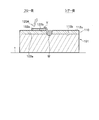
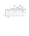
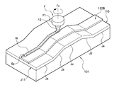
- the joining method according to the eleventh embodiment includes a polymerization step, an arrangement step, a friction stirring step, and a removal step.
- the auxiliary member 120B is placed on the surface of the second metal member 110 in the same manner as in the ninth embodiment.
- the auxiliary member 120B is about half as wide as the auxiliary member 120 of the ninth embodiment.
- the friction stirring step is a step of joining the overlapping portion J11 of the first metal member 101 and the second metal member 110 by friction stirring using the welding rotary tool F.
- the spiral groove of the stirring pin F2 is formed in a counterclockwise direction from the proximal end toward the distal end.
- the rotational center axis Fc of the joining rotary tool F is positioned so as to be slightly on the center side of the auxiliary member 120B from the reference line Z passing through the end surface 120a of the auxiliary member 120B. Then, only the stirring pin F2 rotated to the right is inserted into the overlapping portion J11, and the bonded metal member and the connecting portion F1 are relatively moved while being separated from each other.
- the traveling direction of the joining rotary tool F is set so that the auxiliary member 120B is positioned on the right side of the traveling direction of the joining rotary tool F, and the joining rotary tool F is rotated at high speed.
- the auxiliary member 120B side becomes a flow side (Re side), and the burr
- the insertion position of the welding rotary tool F in this embodiment (the distance between the rotation center axis Fc of the welding rotary tool F and the reference line Z) is assisted only on one side of the welding rotary tool F after the friction stirring step. It adjusts suitably to such an extent that member 120B remains.
- the removal step is a step of removing the auxiliary member 120B from the second metal member 110 as shown in FIG.
- the auxiliary member 120B is bent in a direction (arrow direction) away from the second metal member 110 and removed from the second metal member 110 by, for example, manual work.
- the first metal member 101 and the second metal member 110 are joined, and in addition to the first metal member 101 and the second metal member 110, the auxiliary member 120B is also used.
- the auxiliary member 120B is also used.
- the rotational speed of the joining rotary tool F is set high, there is a tendency that many burrs V are generated on the flow side. That is, in this embodiment, the rotation direction and the traveling direction (bonding conditions) of the bonding rotary tool F are set so that a large number of burrs V are formed on the auxiliary member 120B. Thereby, since the burr
- the auxiliary member 120B may use a removing device or the like, but in the present embodiment, the auxiliary member 120B can be easily removed manually.
- the insertion position of the stirring pin F2 is adjusted so that the auxiliary member 120B does not remain on one side (the left side in the direction of travel of the bonding rotary tool F) after the friction stirring step. It is only necessary to remove the auxiliary member 120B remaining on the surface. This can reduce the labor of the removal process.
- the rotation center axis Fc is slightly shifted to the center side of the auxiliary member 120B from the reference line Z, it is possible to prevent the metal shortage of the joint portion in a balanced manner and more reliably. Further, since the rotation center axis Fc is slightly shifted from the reference line Z toward the center side of the auxiliary member 120B, the stirring pin F2 can be easily inserted into the auxiliary member 120B.
- the first metal member 130 and the second metal member 140 are overlapped.
- the first metal member 130 and the second metal member 140 are formed of a metal capable of friction stir, and the front surface 130a of the first metal member 130 and the front surface 140a and the back surface 140b of the plate-like second metal member 140 are formed. It is curved with an equivalent radius of curvature.
- the overlapping portion J12 is formed.
- the back surface 150b of the plate-like auxiliary member 150 curved in the same shape as the second metal member 140 is brought into surface contact with the surface 140a of the second metal member 140.
- the 1st metal member 130, the 2nd metal member 140, and the auxiliary member 150 are restrained by the mount frame T so that a movement is impossible using a jig
- the friction stirring step is a step of friction stir welding the overlapping portion J12 using the rotating tool F for bonding.
- the stirring pin F2 of the joining rotary tool F is inserted from the surface 150a of the auxiliary member 150 to the first metal member 130 via the second metal member 140, and the joining rotary tool F along the overlapping portion J12. Relative movement.
- the inclination angle of the joining rotary tool F is gradually changed so that the rotation center axis Fc of the joining rotary tool F overlaps the normal line of the auxiliary member 150 and the second metal member 140.
- the insertion depth of the stirring pin F2 is set so that the plasticized region W1 is constant. Since the removal step is equivalent to the ninth embodiment, the description thereof is omitted.
- the joining method according to the twelfth embodiment will be described.
- the butted portions J21 formed by butting the end surfaces 201a and 201a of the first metal member 201A and the second metal member 201B shown in FIG. 50 are joined by friction stir as shown in FIG.
- the first metal member 201A and the second metal member 201B are metal members, and end surfaces 201a and 201a to be abutted have the same shape.
- the first metal member 201A and the second metal member 201B are formed of the same material. This material is not particularly limited as long as it is a metal that can be frictionally stirred, but may be appropriately selected from, for example, aluminum, aluminum alloy, copper, copper alloy, titanium, titanium alloy, magnesium, magnesium alloy, and the like.
- the first metal member 201A and the second metal member 201B are composed of a main body portion 202 that has a rectangular parallelepiped shape and a convex portion 203 that is formed on the main body portion 202 and has a trapezoidal cross section. .
- the surface 203 a of the convex portion 203 is located above the surfaces 202 a and 202 b of the main body portion 202.
- the first surface 203 b of the convex portion 203 is inclined and connects the surface 202 a of the main body portion 202 and the surface 203 a of the convex portion 203.
- the second surface 203 c of the convex portion 203 is inclined and connects the surface 202 b of the main body portion 202 and the surface 203 a of the convex portion 203.
- the butting process is a process of butting the end surfaces 201a and 201a of the first metal member 201A and the second metal member 201B.
- the first metal member 201A and the second metal member 201B are butted so that the surfaces thereof are flush with each other.
- the end surfaces 201a and 201a are brought into surface contact with each other in the butting process to form a butting portion J21.
- the butting portion J21 is formed so that its height position changes. That is, in the butt portion J21, when the height (elevation) of the starting point (insertion position) of the friction stirrer is set as the reference height, there are sections having different reference heights and heights from the starting point to the end point.
- the butting portion J21 includes a first flat portion Ja, a first inclined portion Jb, a second flat portion Jc, a second inclined portion Jd, and a third flat portion Je.
- the placement step is a step of placing the auxiliary member 210 on the first metal member 201A and the second metal member 201B in the butted state shown in FIG.
- the auxiliary member 210 is a metal plate member.
- the auxiliary member 210 is not particularly limited as long as it is a metal capable of friction stirring, but in the present embodiment, the auxiliary member 210 is made of the same material as the first metal member 201A and the second metal member 201B.
- board thickness of the auxiliary member 210 is suitably set so that the plasticization area
- the auxiliary member 210 is a plate-like member having a different thickness and formed with a constant plate thickness.
- the auxiliary member 210 includes base portions 211 and 211, a central portion 212, and inclined portions 213 and 214.
- the central portion 212 is formed at a position higher than the base portions 211 and 211 at the center of the base portions 211 and 211.
- the inclined portion 213 connects one base portion 211 and the central portion 212 obliquely.
- the inclined portion 214 obliquely connects the other base portion 211 and the central portion 212.
- slits 215 and 215 are provided in the vicinity of the center of each end portion of the base portions 211 and 211.
- the back surface of the auxiliary member 210 is brought into surface contact along the center of the surface of the first metal member 201A and the second metal member 201B in the butted state. More specifically, the front surfaces 202a and 202b of the main body portion 202 of the first metal member 201A and the second metal member 201B in the butted state overlap the back surfaces 211b and 211b of the base portions 211 and 211 of the auxiliary member 210, and a convex portion. The front surface 203a of 203 and the back surface 212b of the central portion 212 are overlapped.
- the inclined first surface 203b of the convex portion 203 and the back surface 213b of the inclined portion 213 are overlapped, and the inclined second surface 203c of the convex portion 203 and the back surface 214b of the inclined portion 214 are overlapped.
- the first metal member 201A and the second metal member 201B and the auxiliary member 210 in a butted state are restrained to the gantry T by using a jig (not shown).
- the auxiliary member 210 has a plate shape with different heights in the present embodiment, but may have other shapes as long as it is in surface contact with the surfaces of the first metal member 201A and the second metal member 201B.
- the friction stirring step is a step of joining the butted portions J of the first metal member 201A and the second metal member 201B in the butted state using the joining rotary tool F by friction stirring.
- the joining rotary tool F includes a connecting portion F1 and a stirring pin F2.
- the spiral groove is formed in a counterclockwise direction from the proximal end toward the distal end in order to rotate the joining rotary tool F to the right. In other words, the spiral groove is formed counterclockwise as viewed from above when the spiral groove is traced from the proximal end to the distal end.
- the stirring pin F2 of the rotating tool F for bonding rotated to the right is inserted into the start position Sp set on the surface of the auxiliary member 210.
- the insertion depth of the stirring pin F2 is set so that the stirring pin F2 contacts (reaches) the first metal member 201A and the second metal member 201B.
- the friction stir is performed in a state where the rotation center axis of the welding rotary tool F is always parallel to the vertical axis.
- the first metal member 201A and the second metal member 201B around the stirring pin F2 are frictionally stirred by the friction stirring step, and the first metal member 201A and the second metal member 201B are joined.
- a plasticized region W is formed in the movement locus of the welding rotary tool F.
- Friction stirring is performed in a state where the member 201B is brought into contact.
- the rotation tool F for joining to the gantry T on which the auxiliary member 210, the first metal member 201A, and the second metal member 201B are fixed has a height ( Friction stirring is carried out by moving the surfaces with different elevations up and down.
- the depth Zc of the plasticized region W of the second flat portion Jc can be made substantially equal.
- the “insertion depth” of the stirring pin F2 means a distance from the surface of the auxiliary member 210 to the tip of the stirring pin F2 on the rotation center axis Fc of the rotating tool F for joining.
- the periphery of the stirring pin F2 is frictionally stirred by the above-described friction stirring step, and the first metal member 201A and the second metal member 201B are joined. At this time, as shown in FIGS. 56 and 57, burrs V are formed on the surface portion of the auxiliary member 210. In this embodiment, since the joining rotary tool F is rotated at a high speed, burrs tend to occur more on the flow side than on the shear side described later.
- the removing step is a step of removing the auxiliary member 210 from the first metal member 201A and the second metal member 201B as shown in FIGS.
- the auxiliary member 210 is bent from both sides in a direction away from the first metal member 201A and the second metal member 201B, for example, by manual work, and removed from the first metal member 201A and the second metal member 201B.
- one of the slits 215 and 215 (see FIG. 54) of the auxiliary member 210 is used as a starting point, and the end is turned up and removed by bending.
- the first metal member 201A and the second metal member 201B are joined, and in addition to the first metal member 201A and the second metal member 201B, the auxiliary member 210 is simultaneously used.
- the joint plasticization region W.
- groove is formed in the surface of the butt
- the stirring pin F2 by inserting the stirring pin F2 from the central portion of the auxiliary member 210 toward the abutting portion J21, it is possible to more reliably prevent a shortage of metal at the joint portion and to replenish the metal in a balanced manner. Further, by inserting the stirring pin F2 from the center of the auxiliary member 210, the stirring pin F2 can be easily inserted into the auxiliary member 210.
- the burrs V and V are formed on the auxiliary members 210 separated by the friction stirring process, respectively, but the burrs V and V can be removed together with the auxiliary members 210 in the removing process.
- flash V and V can be performed easily.
- the auxiliary member 210 may be removed using a removing device or the like, but in this embodiment, the auxiliary member 10 can be easily removed manually.
- the auxiliary member 210 is set to be significantly thinner than the first metal member 201A and the second metal member 201B.
- the auxiliary member 210 is blown to the outside due to the contact between the shoulder portion and the auxiliary member 210, and the metal shortage at the joint portion where the butt portion J21 is joined cannot be compensated.
- the friction stir is performed while only the stirring pin F2 of the rotating tool F for welding is brought into contact with the auxiliary member 210, the first metal member 201A, and the second metal member 201B, the auxiliary member 210 is skipped to the outside. It is possible to make up for the metal shortage at the joint without being damaged.
- the deep position of the butting portion J21 on the lower side of the auxiliary member 210 is joined in a state where the load acting on the friction stirrer is reduced as compared with the case where the shoulder portion of the rotary tool is brought into contact. can do.
- FIG. 60 is a cross-sectional view showing a friction stirring step of a modification of the joining method according to the twelfth embodiment.
- the friction stir is performed while inserting the welding rotary tool F perpendicularly to the upper surface of the abutting portion J.
- the rotation center axis Fc of the welding rotary tool F is set as the vertical axis as in the twelfth embodiment. Friction stirring is performed in a parallel state.
- the bonding rotary tool F is inclined with respect to the vertical axis, and the bonding rotation is performed with respect to the surfaces of the first metal member 201A and the second metal member 201B. Friction stirring is performed with the rotation center axis Fc of the tool F being vertical.
- the rotating tool F for joining it is preferable to attach the rotating tool F for joining to a robot arm having a driving unit such as a spindle unit at the tip and perform friction stirring.
- a friction stirrer According to such a friction stirrer, the angle of the rotation center axis Fc of the joining rotary tool F can be easily changed.
- the first metal member 201A and the second metal can be changed by changing the angle of the rotation center axis Fc of the welding rotary tool F with respect to the vertical axis during friction stirring. Friction stirring can be continuously performed in a state where the welding rotary tool F is always perpendicular to the surface of the member 201B.
- the joining method according to the thirteenth embodiment is different from the twelfth embodiment in that the joining rotary tool F is inserted from the end face 210a of the auxiliary member 210A shown in FIG. Further, the auxiliary member 210A is different in that slits 215 and 215 are not formed.
- the joining method according to the thirteenth embodiment will be described with a focus on the differences from the twelfth embodiment.
- the joining method according to the present embodiment performs a butt process, an arrangement process, a friction stirring process, and a removal process. Since the matching process is the same as that of the twelfth embodiment, the description thereof is omitted.
- the end surface 210a is aligned with the surface of the first metal member 201A and on the boundary line C of the butted portion J21 of the first metal member 201A and the second metal member 201B.
- the member 210A is disposed.
- the auxiliary member 210A of the thirteenth embodiment is about half the width of the auxiliary member 210 of the twelfth embodiment.
- the friction stirring step is a step of joining the butted portions J of the first metal member 201A and the second metal member 201B by friction stirring using the welding rotary tool F.
- the spiral groove of the stirring pin F2 is formed in a clockwise direction from the proximal end toward the distal end. In other words, when the spiral groove is traced from the proximal end to the distal end, the spiral groove is formed clockwise when viewed from above.
- the friction stirring step only the stirring pin F2 rotated counterclockwise is inserted, and the metal member to be joined and the connecting portion F1 are moved relative to each other while being separated. In other words, the friction stir welding is performed with the base end portion of the stirring pin F2 exposed.
- the friction stirring step as shown in FIG. 62, the first metal member 201A, the second metal member 201B, the auxiliary member 210A, and the rotation center axis Fc of the welding rotary tool F are overlapped on the boundary line C.
- the joining rotary tool F is relatively moved in a state where the stirring pin F2 is in contact with the stirring pin F2.
- the joining rotary tool F is set so that the shear side (advancing side) is the right side in the traveling direction.
- the direction of movement and the direction of rotation are set.
- the rotation direction and the traveling direction of the joining rotary tool F are not limited to those described above, and may be set as appropriate.
- the rotational speed of the joining rotary tool F is set high, as shown in FIG. 64, many burrs V tend to occur on the flow side (Re side) outside the plasticizing region W. .
- the moving speed (feeding speed) of the joining rotary tool F can be increased by setting the rotational speed of the joining rotary tool F faster. Thereby, a joining cycle can be shortened.
- the joining conditions it is preferable to set the joining conditions so that the burr V is formed on the auxiliary member 210A.
- the insertion depth of the stirring pin F2 is set so that the stirring pin F2 contacts (reaches) the first metal member 201A and the second metal member 201B.
- the removal step is a step of removing the auxiliary member 210A from the first metal member 201A as shown in FIG.
- the auxiliary member 210A is bent in a direction away from the first metal member 201A as indicated by an arrow by manual work and removed from the first metal member 201A.
- 201 A of 1st metal members and the 2nd metal member 201B are joined by the butt
- the first metal member 201A and the second metal member 201B are joined at the abutting portion J21, and the auxiliary member 210A is also friction stir welded at the same time. It is possible to prevent metal shortage in (plasticized region W). Thereby, it can prevent that a ditch
- the burrs V are formed on the auxiliary member 210A by the friction stirring process, but the auxiliary member 210A can be removed in the removal process.
- flash V can be performed easily.
- the auxiliary member 210A may be removed using a removing device or the like, but in the present embodiment, the auxiliary member 210A can be easily removed manually in the direction indicated by the arrow.
- the joining method according to the fourteenth embodiment includes a butting process, an arranging process, a friction stirring process, and a removing process.
- the auxiliary member 210B is arranged mainly on the surface of the second metal member 201B, and the end surface 210a slightly protrudes from the boundary line C to the surface side of the first metal member 201A.
- the auxiliary member 210B is disposed.
- the distance from the boundary line C to the end face 210a is such that a metal shortage does not occur in the joint portion (plasticization region W) after the friction stirring process described later, and the auxiliary member 210B remains on the first metal member 201A after the friction stirring process. Set to a level that does not.
- the friction stirring step is a step of joining the butted portions J21 of the first metal member 201A and the second metal member 201B by friction stirring using the rotating tool F for joining.
- the spiral groove of the stirring pin F2 is formed in a counterclockwise direction from the proximal end toward the distal end.
- the traveling direction of the joining rotary tool F is set so that the auxiliary member 210B is positioned on the right side of the traveling direction of the joining rotary tool F, and the joining rotary tool F is rotated at a high speed.
- occur
- the removing step is a step of removing the auxiliary member 210B from the second metal member 201B as shown in FIG.
- the auxiliary member 210B is bent in a direction (arrow direction) away from the second metal member 201B, for example, by manual work, and removed from the second metal member 201B.
- the first metal member 201A and the second metal member 201B are joined, and the auxiliary member 210B is simultaneously added to the first metal member 201A and the second metal member 201B.
- the auxiliary member 210B is simultaneously added to the first metal member 201A and the second metal member 201B.
- the rotational speed of the joining rotary tool F is set high, there is a tendency that many burrs V are generated on the flow side outside the plasticizing region W. That is, the rotation direction and the traveling direction (bonding conditions) of the bonding rotary tool F are set so that the burrs V are concentrated on the auxiliary member 210B remaining after the friction stirring step. Thereby, since the burr
- the auxiliary member 210B may use a removing device or the like, in this embodiment, the auxiliary member 210B can be easily removed manually.
- the auxiliary member 210B does not remain on the other side of the boundary line C (the side of the first metal member 201A and the second metal member 201B where the contact area ratio with the auxiliary member 210B is small) after the friction stirring step. Since the arrangement position of the auxiliary member 210B is adjusted, the removal step is performed on one side of the boundary line C (the side having the larger contact area ratio with the auxiliary member 210B among the first metal member 201A and the second metal member 201B). It is only necessary to remove the remaining auxiliary member 210B. This can reduce the labor of the removal process.
- the arrangement position of the auxiliary member 210B is a position where the end surface 210a slightly protrudes beyond the boundary C to the first metal member 201A side (the other side).
- the protruding portion of the auxiliary member 210B is also frictionally agitated by the agitating pin F2 and compensated in the joining portion (plasticization region W), so that a sufficient balance of the joining portion can be prevented more reliably. Can do.
- the rotation center axis Fc is slightly shifted from the end surface 210a of the auxiliary member 210B toward the center, the stirring pin F2 can be easily inserted into the auxiliary member 210B.
- the first metal member 230A and the second metal member 230A and the second metal member 230A and the second metal member 230B, whose upper surfaces are curved, are abutted against each other.
- the metal member 230B is formed of a metal that can be frictionally stirred, and is curved with an equivalent radius of curvature so that the surfaces 230a and 230a are flush with each other.
- the back surface 250b of the plate-like auxiliary member 250 curved in the same shape as the first metal member 230A and the second metal member 230B is placed at the center of the surface of the first metal member 230A and the second metal member 230B in a butted state. Surface contact along the part. Note that the first metal member 230A, the second metal member 230B, and the auxiliary member 250 are restrained so as not to move on the gantry T using a jig (not shown).
- the friction stir process is a process in which the butt joint J21 is friction stir welded using the welding rotary tool F.
- the agitation pin F2 of the joining rotary tool F is inserted from the surface 250a of the auxiliary member 250 to the abutting portion J21 of the first metal member 230A and the second metal member 230B, and the joining rotation is performed along the abutting portion J21.
- the tool F is moved relatively.
- the inclination angle of the welding rotary tool F is gradually changed so that the rotation center axis Fc of the welding rotary tool F overlaps the normal lines of the auxiliary member 250, the first metal member 230A, and the second metal member 230B.
- the insertion depth of the stirring pin F2 is set so that the depth of the plasticized region W1 is constant. Since the removal step is the same as that of the twelfth embodiment, the description thereof is omitted.
- the removing step is performed in the present embodiment, the auxiliary member may be left as it is without removing the auxiliary member.
Landscapes
- Engineering & Computer Science (AREA)
- Mechanical Engineering (AREA)
- Pressure Welding/Diffusion-Bonding (AREA)
Abstract
接合部の金属不足を防ぐことができる接合方法を提供することを課題とする。攪拌ピン(F2)を備えた接合用回転ツール(F)を用いて第一金属部材(1)と第二金属部材(2)とを接合する接合方法であって、第一金属部材(1)と第二金属部材(2)とを突合わせて突合せ部(J1)を形成する突合せ工程と、第一金属部材(1)又は第二金属部材(2)に面接触するように補助部材(10)を配置する配置工程と、攪拌ピン(F2)のみを第一金属部材(1)、第二金属部材(2)及び補助部材(10)に接触させた状態で突合せ部(J1)に沿って接合用回転ツール(F)を相対移動させて第一金属部材(1)、第二金属部材(2)及び補助部材(10)を接合する摩擦攪拌工程と、を含むことを特徴とする。
Description
本発明は、金属部材同士を摩擦攪拌で接合する接合方法に関する。
例えば、特許文献1には、第一金属部材と第二金属部材とを摩擦攪拌で接合する接合方法が開示されている。当該接合方法では、第一金属部材と第二金属部材とを突き合わせて突合せ部を形成した後、回転ツールの攪拌ピンのみを第一金属部材及び第二金属部材に接触させた状態で突合せ部に対して摩擦攪拌を行うというものである。
また、例えば、特許文献2には、第一金属部材と第二金属部材を重ね合わせて重合部を形成した後、第二金属部材の表面から回転ツールを挿入して重合部を摩擦攪拌接合する接合方法が記載されている。当該摩擦攪拌接合では、攪拌ピンのみを第二金属部材に接触させた状態で摩擦攪拌を行うというものである。
例えば、特許文献3には、表面の高さが変化する金属部材同士の端面を突き合わせて高さが変化する突合せ部を形成し、回転ツールの攪拌ピンのみを金属部材同士の突合せ部に接触させた状態で摩擦攪拌を行って接合する接合方法が記載されている。
特許文献1に係る接合方法であると、塑性流動化した金属を回転ツールのショルダ部で押さえないため、塑性流動化した金属が外部に溢れ出し接合部が金属不足になるという問題がある。さらに、長尺の金属部材同士を突合せると、突合せ部に隙間が生じる場合があり、接合部が金属不足になるという問題がある。
特許文献2に係る接合方法であると、塑性流動化した金属を回転ツールのショルダ部で押さえないため、塑性流動化した金属が外部に溢れ出し接合部が金属不足になり、第二金属部材の表面に凹溝が形成されるという問題がある。
特許文献3に係る接合方法であると、塑性流動化した金属を回転ツールのショルダ部で押さえないため、塑性流動化した金属が外部に溢れ出し接合部が金属不足になり、金属部材同士の突合せ部の表面に凹溝が形成されるという問題がある。
そこで、本発明は、接合部の金属不足を防ぐことができる接合方法を提供することを課題とする。
前記課題を解決するために、本発明は、攪拌ピンを備えた回転ツールを用いて第一金属部材と第二金属部材とを接合する接合方法であって、前記第一金属部材と前記第二金属部材とを突き合わせて突合せ部を形成する突合せ工程と、前記第一金属部材又は前記第二金属部材に面接触するように補助部材を配置する配置工程と、回転する前記攪拌ピンを前記補助部材の表面側から挿入し、前記攪拌ピンのみを前記第一金属部材、前記第二金属部材及び前記補助部材に接触させた状態で前記突合せ部に沿って前記回転ツールを相対移動させて前記第一金属部材、前記第二金属部材及び前記補助部材を接合する摩擦攪拌工程と、を含む、ことを特徴とする。
また、本発明は、攪拌ピンを備えた回転ツールを用いて第一金属部材と第二金属部材とを接合する接合方法であって、前記第一金属部材と前記第二金属部材とを突き合わせて突合せ部を形成する突合せ工程と、前記第一金属部材及び前記第二金属部材の両方に面接触するように補助部材を配置する配置工程と、回転する前記攪拌ピンを前記補助部材の表面側から挿入し、前記攪拌ピンのみを前記第一金属部材、前記第二金属部材及び前記補助部材に接触させた状態で前記突合せ部に沿って前記回転ツールを相対移動させて前記第一金属部材、前記第二金属部材及び前記補助部材を接合する摩擦攪拌工程と、を含む、ことを特徴とする。
また、本発明は、攪拌ピンを備えた回転ツールを用いて第一金属部材と第二金属部材とを接合する接合方法であって、前記第一金属部材と前記第二金属部材とを突き合わせて突合せ部を形成する突合せ工程と、前記第一金属部材及び前記第二金属部材の両方に面接触するように補助部材を配置する配置工程と、回転する前記攪拌ピンを前記補助部材の表面側から挿入し、前記攪拌ピンのみを前記第一金属部材、前記第二金属部材及び前記補助部材に接触させた状態で前記突合せ部に沿って前記回転ツールを相対移動させて前記第一金属部材、前記第二金属部材及び前記補助部材を接合する摩擦攪拌工程と、を含む、ことを特徴とする。
かかる接合方法によれば、第一金属部材と第二金属部材とが接合されるとともに、第一金属部材及び第二金属部材に加え、補助部材も同時に摩擦攪拌接合することにより、接合部の金属不足を防ぐことができる。
また、バリが形成された前記補助部材を前記第一金属部材又は前記第二金属部材から除去する除去工程を含むことが好ましい。かかる接合方法によれば、バリを補助部材ごと除去できるので除去工程が容易となる。
また、前記摩擦攪拌工程では、摩擦攪拌接合で発生するバリが前記補助部材に形成されるように接合条件を設定することが好ましい。かかる接合方法によれば、バリを除去する作業をより容易に行うことができる。
また、前記配置工程では、前記補助部材を第一金属部材及び前記第二金属部材の一方に配置しつつ、前記摩擦攪拌工程後に他方側に補助部材が残存しない程度に前記突合せ部を挟んで他方側にわずかに突出するように配置し、前記摩擦攪拌工程では、摩擦攪拌接合で発生するバリが、前記補助部材のうち第一金属部材及び前記第二金属部材の一方側に形成されるように接合条件を設定することが好ましい。
かかる接合方法によれば、バリを除去する作業をより容易に行うことができる。また、突合せ部を挟んで他方側にわずかに補助部材を突出させる分、接合部の金属不足をより確実に防ぐことができる。
また、本発明は、攪拌ピンを備えた回転ツールを用いて第一金属部材と第二金属部材とを接合する接合方法であって、前記第一金属部材と前記第二金属部材とを突き合わせて突合せ部を形成する突合せ工程と、前記第一金属部材又は前記第二金属部材に面接触するように補助部材を配置する配置工程と、回転する前記攪拌ピンを前記補助部材の表面側から挿入し、前記攪拌ピンのみを前記第一金属部材、前記第二金属部材及び前記補助部材に接触させた状態で前記突合せ部に沿って前記回転ツールを相対移動させて前記第一金属部材、前記第二金属部材及び前記補助部材を接合する摩擦攪拌工程と、を含み、前記突合せ工程において、前記突合せ部を形成する際に前記突合せ部に隙間が生じていることを特徴とする。
また、本発明は、攪拌ピンを備えた回転ツールを用いて第一金属部材と第二金属部材とを接合する接合方法であって、前記第一金属部材と前記第二金属部材とを突き合わせて突合せ部を形成する突合せ工程と、前記第一金属部材及び前記第二金属部材の両方に面接触するように補助部材を配置する配置工程と、回転する前記攪拌ピンを前記補助部材の表面側から挿入し、前記攪拌ピンのみを前記第一金属部材、前記第二金属部材及び前記補助部材に接触させた状態で前記突合せ部に沿って前記回転ツールを相対移動させて前記第一金属部材、前記第二金属部材及び前記補助部材を接合する摩擦攪拌工程と、を含み、前記突合せ工程において、前記突合せ部を形成する際に前記突合せ部に隙間が生じていることを特徴とする。
また、本発明は、攪拌ピンを備えた回転ツールを用いて第一金属部材と第二金属部材とを接合する接合方法であって、前記第一金属部材と前記第二金属部材とを突き合わせて突合せ部を形成する突合せ工程と、前記第一金属部材及び前記第二金属部材の両方に面接触するように補助部材を配置する配置工程と、回転する前記攪拌ピンを前記補助部材の表面側から挿入し、前記攪拌ピンのみを前記第一金属部材、前記第二金属部材及び前記補助部材に接触させた状態で前記突合せ部に沿って前記回転ツールを相対移動させて前記第一金属部材、前記第二金属部材及び前記補助部材を接合する摩擦攪拌工程と、を含み、前記突合せ工程において、前記突合せ部を形成する際に前記突合せ部に隙間が生じていることを特徴とする。
かかる接合方法によれば、第一金属部材と第二金属部材とが接合されるとともに、第一金属部材及び第二金属部材に加え、補助部材も同時に摩擦攪拌接合することにより、接合部の金属不足を防ぐことができる。また、前記突合せ工程において、前記突合せ部を形成する際に突合せ部に隙間が生じている場合であっても、塑性流動化した金属が当該隙間を埋めることができる。
また、前記課題を解決するために、本発明は、攪拌ピンを備えた回転ツールを用いて第一金属部材と第二金属部材とを接合する接合方法であって、前記第一金属部材と、前記第一金属部材よりも薄い前記第二金属部材とを用意する準備工程と、前記第一金属部材及び前記第二金属部材の端面同士を突き合わせて突合せ部を形成するとともに第一の段差を形成する突合せ工程と、前記第一の段差に補助部材を配置する配置工程と、前記第一金属部材及び前記第二金属部材の表面側から回転する前記回転ツールを前記第一の段差に挿入し、前記攪拌ピンのみを前記第一金属部材、第二金属部材及び補助部材に接触させた状態で前記突合せ部に沿って前記回転ツールを相対移動させて摩擦攪拌接合を行う摩擦攪拌工程と、を含むことを特徴とする。
また、本発明は、攪拌ピンを備えた回転ツールを用いて第一金属部材と第二金属部材とを接合する接合方法であって、前記第一金属部材及び前記第二金属部材の端面同士を突き合わせて突合せ部を形成するとともに第一の段差を形成する突合せ工程と、前記第一の段差に補助部材を配置する配置工程と、前記第一金属部材及び前記第二金属部材の表面側から回転する前記回転ツールを前記第一の段差に挿入し、前記攪拌ピンのみを前記第一金属部材、第二金属部材及び補助部材に接触させた状態で前記突合せ部に沿って前記回転ツールを相対移動させて摩擦攪拌接合を行う摩擦攪拌工程と、を含むことを特徴とする。
また、本発明は、攪拌ピンを備えた回転ツールを用いて第一金属部材と第二金属部材とを接合する接合方法であって、前記第一金属部材及び前記第二金属部材の端面同士を突き合わせて突合せ部を形成するとともに第一の段差を形成する突合せ工程と、前記第一の段差に補助部材を配置する配置工程と、前記第一金属部材及び前記第二金属部材の表面側から回転する前記回転ツールを前記第一の段差に挿入し、前記攪拌ピンのみを前記第一金属部材、第二金属部材及び補助部材に接触させた状態で前記突合せ部に沿って前記回転ツールを相対移動させて摩擦攪拌接合を行う摩擦攪拌工程と、を含むことを特徴とする。
かかる接合方法によれば、第一金属部材と第二金属部材とが接合されるとともに、第一金属部材及び第二金属部材に加え、補助部材も同時に摩擦攪拌接合することにより、接合部の金属不足を防ぐことができる。
また、バリが形成された前記補助部材を前記第一金属部材及び前記第二金属部材から除去する除去工程を含むことが好ましい。かかる接合方法によれば、バリを補助部材ごと除去できるので除去工程が容易となる。
また、前記摩擦攪拌工程では、摩擦攪拌接合で発生するバリが前記補助部材に形成されるように、接合条件を設定することが好ましい。かかる接合方法によれば、バリを除去する作業をより容易に行うことができる。
また、前記配置工程において、前記第一金属部材の表面と前記補助部材の表面とが面一になるように前記補助部材を配置することが好ましい。かかる接合方法によれば、回転ツールを容易に挿入することができる。
また、前記配置工程において、前記第一金属部材の表面よりも前記補助部材の表面が高い位置となるように前記補助部材を配置することが好ましい。かかる接合方法によれば、接合部の金属不足を確実に防ぐことができる。
また、前記配置工程において、前記第一金属部材の表面よりも前記補助部材の表面が低い位置となるように前記補助部材を配置することが好ましい。かかる接合方法によれば、補助部材を容易に除去することができる。
また、前記摩擦攪拌工程において、前記回転ツールの回転中心軸を前記突合せ部に対して前記補助部材側に偏移させた状態で、前記突合せ部に沿って摩擦攪拌接合を行うことが好ましい。また、前記摩擦攪拌工程において、前記回転ツールの回転中心軸を前記補助部材側に傾斜させた状態で、前記突合せ部に沿って摩擦攪拌接合を行うことが好ましい。
かかる接合方法によれば、補助部材が多く摩擦攪拌されるため、接合部の金属不足を確実に防ぐことができる。
また、前記課題を解決するために、本発明は、攪拌ピンを備えた回転ツールを用いて第一金属部材と第二金属部材とを接合する接合方法であって、前記第一金属部材の表面に前記第二金属部材の裏面を重ね合せて重合部を形成する重合工程と、前記第二金属部材の表面に面接触するように補助部材を配置する配置工程と、回転する前記攪拌ピンを前記補助部材の表面側から挿入し、前記攪拌ピンのみを、前記第二金属部材及び前記補助部材、又は、前記第一金属部材、前記第二金属部材及び前記補助部材に接触させた状態で前記回転ツールを相対移動させて前記第一金属部材、前記第二金属部材及び前記補助部材を接合する摩擦攪拌工程と、を含むことを特徴とする。
かかる接合方法によれば、重合部が接合されるとともに、第一金属部材及び第二金属部材に加え、補助部材も同時に摩擦攪拌接合することにより、接合部の金属不足を防ぐことができる。これにより、第二金属部材の表面に凹溝ができるのを防ぐことができる。
また、バリが形成された前記補助部材を前記第二金属部材から除去する除去工程を含むことが好ましい。かかる接合方法によれば、バリを補助部材ごと除去することができる。
また、前記摩擦攪拌工程では、前記補助部材の中央部に前記攪拌ピンを挿入することが好ましい。かかる接合方法によれば、金属不足をより確実に防ぐことができる。また、補助部材に回転ツールを容易に挿入することができる。
また、前記補助部材の端面を通り前記第一金属部材及び前記第二金属部材に直交する線を基準線とした場合、前記摩擦攪拌工程では、前記回転ツールの回転中心軸と前記基準線とが重なるように前記攪拌ピンを相対移動させるとともに、バリが前記補助部材に形成されるように接合条件を設定することが好ましい。
かかる接合方法によれば、回転ツールに対して片側にのみ補助部材が残存するため、除去工程を容易に行うことができる。
また、前記補助部材の端面を通り前記第一金属部材及び前記第二金属部材に直交する線を基準線とした場合、前記摩擦攪拌工程では、摩擦攪拌工程を行った後に前記回転ツールの片側にのみ補助部材が残存する程度に前記回転ツールの回転中心軸を前記基準線よりもわずかに前記補助部材の中央側に偏移させて相対移動させるとともに、残存する前記補助部材にバリが形成されるように接合条件を設定することが好ましい。
かかる接合方法によれば、回転ツールに対して方側にのみ補助部材が残存するため、除去工程を容易に行うことができる。また、回転ツールの回転中心軸が基準線よりも補助部材の中央側に偏移しているため接合部の金属不足をより確実に防ぐことができる。また、補助部材に回転ツールを容易に挿入することができる。
また、前記課題を解決するために本発明は、攪拌ピンを備えた回転ツールを用いて第一金属部材と第二金属部材とを接合する接合方法であって、少なくとも表面の高さが変化する前記第一金属部材の表面に、少なくとも裏面の高さが変化する前記第二金属部材の裏面を重ね合せて高さが変化する重合部を形成する重合工程と、前記第二金属部材の表面に面接触するように補助部材を配置する配置工程と、回転する前記攪拌ピンを前記補助部材の表面側から挿入し、前記回転ツールの前記攪拌ピンのみを前記第二金属部材及び前記補助部材、又は、前記第一金属部材、前記第二金属部材及び前記補助部材に接触させた状態で前記回転ツールを相対移動させて前記第一金属部材、前記第二金属部材及び前記補助部材を接合する摩擦攪拌工程と、を含むことを特徴とする。
かかる方法によれば、高さが変化する重合部が接合されるとともに、高さが変化する第一金属部材及び第二金属部材に加え、補助部材も同時に摩擦攪拌接合することにより、接合部の金属不足を防ぐことができる。これにより、第二金属部材の表面に凹溝ができるのを防ぐことができる。
また、バリが形成された前記補助部材を前記第二金属部材から除去する除去工程を含むことを特徴とする。
かかる方法によれば、バリを補助部材ごと除去することができる。
また、前記摩擦攪拌工程では、前記補助部材の中央部に前記攪拌ピンを挿入することを特徴とする。
かかる方法によれば、金属不足をより確実に防ぐことができる。また、補助部材に回転ツールを容易に挿入することができる。
また、前記補助部材の端面を通り前記第一金属部材及び前記第二金属部材に直交する線を基準線とした場合、前記摩擦攪拌工程では、前記回転ツールの回転中心軸と前記基準線とが重なるように前記攪拌ピンを相対移動させるとともに、バリが前記補助部材に形成されるように接合条件を設定することを特徴とする。
かかる方法によれば、回転ツールに対して片側にのみ補助部材が残存するため、除去工程を容易に行うことができる。
また、前記補助部材の端面を通り前記第一金属部材及び前記第二金属部材に直交する線を基準線とした場合、前記摩擦攪拌工程では、前記摩擦攪拌工程を行った後に前記回転ツールの片側にのみ補助部材が残存する程度に前記回転ツールの回転中心軸を前記基準線よりもわずかに前記補助部材の中央側に偏移させて相対移動させるとともに、残存する前記補助部材にバリが形成されるように接合条件を設定することを特徴とする。
かかる方法によれば、回転ツールに対して方側にのみ補助部材が残存するため、除去工程を容易に行うことができる。また、回転ツールの回転中心軸が基準線よりも補助部材の中央側に偏移しているため接合部の金属不足をより確実に防ぐことができる。また、補助部材に回転ツールを容易に挿入することができる。
また、このような課題を解決するために本発明は、攪拌ピンを備えた回転ツールを用いて第一金属部材と第二金属部材とを接合する接合方法であって、表面の高さが変化する前記第一金属部材と表面の高さが変化する前記第二金属部材とを突き合わせて突合せ部を形成する突合せ工程と、前記第一金属部材又は前記第二金属部材に面接触するように補助部材を配置する配置工程と、回転する前記攪拌ピンを前記補助部材の表面側から高さが変化する前記突合せ部に対して挿入し、前記回転ツールの前記攪拌ピンのみを前記第一金属部材、前記第二金属部材及び前記補助部材に接触させた状態で前記突合せ部に沿って前記回転ツールを相対移動させて前記第一金属部材、前記第二金属部材及び前記補助部材を接合する摩擦攪拌工程と、を含むことを特徴とする。
かかる方法によれば、高さが変化する突合せ部が接合されるとともに、高さが変化する第一金属部材及び第二金属部材に加え、補助部材も同時に摩擦攪拌接合することにより、接合部の金属不足を防ぐことができる。これにより、第一金属部材及び第二金属部材の表面に凹溝ができるのを防ぐことができる。
また、バリが形成された前記補助部材を前記第一金属部材又は前記第二金属部材から除去する除去工程を含むことを特徴とする。
かかる方法によれば、バリを補助部材ごと除去することができる。
また、前記摩擦攪拌工程では、摩擦攪拌接合で発生するバリが前記補助部材に形成されるように接合条件を設定することを特徴とする。
かかる方法によれば、補助部材ごと全てのバリを除去することができる。
また、本発明は、攪拌ピンを備えた回転ツールを用いて第一金属部材と第二金属部材とを接合する接合方法であって、表面の高さが変化する前記第一金属部材と表面の高さが変化する前記第二金属部材とを突き合わせて突合せ部を形成する突合せ工程と、前記第一金属部材及び前記第二金属部材の両方に面接触するように補助部材を配置する配置工程と、回転する前記攪拌ピンを前記補助部材の表面側から高さが変化する前記突合せ部に対して挿入し、前記回転ツールの前記攪拌ピンのみを前記第一金属部材、前記第二金属部材及び前記補助部材に接触させた状態で前記突合せ部に沿って前記回転ツールを相対移動させて前記第一金属部材、前記第二金属部材及び前記補助部材を接合する摩擦攪拌工程と、を含むことを特徴とする。
かかる方法によれば、高さが変化する突合せ部が接合されるとともに、高さが変化する第一金属部材及び第二金属部材に加え、補助部材も同時に摩擦攪拌接合することにより、接合部の金属不足を防ぐことができる。これにより、第一金属部材及び第二金属部材の表面に凹溝ができるのを防ぐことができる。また、補助部材の中央付近から攪拌ピンを突合せ部まで挿入できるので、攪拌ピンを補助部材に容易に挿入することができる。
また、バリが形成された前記補助部材を前記第一金属部材及び前記第二金属部材から除去する除去工程と、を含むことを特徴とする。
かかる方法によれば、摩擦攪拌工程によって分断された補助部材にそれぞれバリが形成されるが、除去工程において、バリを補助部材ごと取り除くことができる。
また、前記配置工程では、前記補助部材を前記第一金属部材及び前記第二金属部材のいずれか一方に配置しつつ、前記突合せ部を挟んで他方側にわずかに突出するように配置し、前記摩擦攪拌工程では、摩擦攪拌接合で発生するバリが、前記補助部材のうち前記第一金属部材及び前記第二金属部材のいずれか一方側に形成されるように接合条件を設定することを特徴とする。
かかる方法によれば、補助部材のわずかに突出した部分が攪拌ピンで摩擦攪拌されて接合部に補填されるので、接合部の金属不足をバランス良く、かつ、より確実に防ぐことができる。また、突合せ部に挿入される回転中心軸が、補助部材の端面から中央側にわずかにずれた位置となるので、攪拌ピンを補助部材に容易に挿入することができる。
また、前記攪拌ピンの周面に螺旋溝が刻設されており、前記回転ツールを右回転させる場合は、前記螺旋溝を前記攪拌ピンの基端側から先端側に向けて左回りに刻設し、前記回転ツールを左回転させる場合は、前記螺旋溝を前記攪拌ピンの基端側から先端側に向けて右回りに刻設することを特徴とする。
かかる方法によれば、塑性流動化した金属材料が螺旋溝に導かれて攪拌ピンの先端側に移動するため、金属部材の外部に溢れ出る金属の量を少なくすることができる。
本発明に係る接合方法によれば、接合部の金属不足を防ぐことができる。
[第一実施形態]
本発明の第一実施形態に係る接合方法について図面を参照して詳細に説明する。本実施形態に係る接合方法では、突合せ工程と、配置工程と、摩擦攪拌工程と、除去工程と、を行う。なお、以下の説明における「表面」とは、「裏面」の反対側の面という意味である。
本発明の第一実施形態に係る接合方法について図面を参照して詳細に説明する。本実施形態に係る接合方法では、突合せ工程と、配置工程と、摩擦攪拌工程と、除去工程と、を行う。なお、以下の説明における「表面」とは、「裏面」の反対側の面という意味である。
突合せ工程は、図1に示すように第一金属部材1と第二金属部材2とを突き合わせる工程である。第一金属部材1及び第二金属部材2は、金属製の板状部材である。第一金属部材1及び第二金属部材2の材料は、摩擦攪拌可能な金属であれば特に制限されないが、例えば、アルミニウム、アルミニウム合金、銅、銅合金、チタン、チタン合金、マグネシウム、マグネシウム合金等から適宜選択すればよい。第一金属部材1及び第二金属部材2の板厚は同等になっている。第一金属部材1及び第二金属部材2の板厚は適宜設定すればよい。
突合せ工程では、第一金属部材1の端面1aと、第二金属部材2の端面2aとを突き合わせて突合せ部J1を形成する。突合せ部J1を形成する際に、第一金属部材1の端面1aと第二金属部材2の端面2aとの間に隙間が生じている場合がある。隙間は1mm程度である。第一金属部材1の表面1bと、第二金属部材2の表面2bとは面一になる。
配置工程は、第一金属部材1又は第二金属部材2に補助部材10を配置する工程である。補助部材10は金属製の板状部材である。補助部材10は摩擦攪拌可能な金属であれば特に制限されないが、本実施形態では第一金属部材1及び第二金属部材2と同じ材料になっている。補助部材10の板厚は、後記する摩擦攪拌工程後の塑性化領域Wが金属不足にならないように適宜設定する。本実施形態では、補助部材10の板厚は第一金属部材1よりも薄く設定している。
配置工程では、補助部材10の裏面10cと第二金属部材2の表面2bとを面接触させる。補助部材10は、第二金属部材2(又は第一金属部材1)のみと面接触するように配置する。本実施形態では、補助部材10の端面10aと第二金属部材2の端面2aとが面一となるように配置する。また、第一金属部材1、第二金属部材2及び補助部材10を治具(図示省略)を用いて架台Tに移動不能に拘束する。なお、補助部材10は本実施形態では板状としているが、他の形状であってもよい。
摩擦攪拌工程は、図2に示すように、接合用回転ツールFを用いて第一金属部材1と第二金属部材2との突合せ部J1を摩擦攪拌によって接合する工程である。接合用回転ツールFは、連結部F1と、攪拌ピンF2とで構成されている。接合用回転ツールFは、特許請求の範囲の「回転ツール」に相当する。接合用回転ツールFは、例えば工具鋼で形成されている。連結部F1は、摩擦攪拌装置の回転軸(図示省略)に連結される部位である。連結部F1は円柱状を呈している。
攪拌ピンF2は、連結部F1から垂下しており、連結部F1と同軸になっている。攪拌ピンF2は連結部F1から離間するにつれて先細りになっている。攪拌ピンF2の外周面には螺旋溝が刻設されている。本実施形態では、接合用回転ツールFを左回転させるため、螺旋溝は、基端から先端に向かうにつれて右回りに形成されている。言い換えると、螺旋溝は、螺旋溝を基端から先端に向けてなぞると上から見て右回りに形成されている。
なお、接合用回転ツールFを右回転させる場合は、螺旋溝を基端から先端に向かうにつれて左回りに形成することが好ましい。言い換えると、この場合の螺旋溝は、螺旋溝を基端から先端に向けてなぞると上から見て左回りに形成されている。螺旋溝をこのように設定することで、摩擦攪拌の際に塑性流動化した金属が螺旋溝によって攪拌ピンF2の先端側に導かれる。これにより、被接合金属部材(第一金属部材1、第二金属部材2及び補助部材10)の外部に溢れ出る金属の量を少なくすることができる。螺旋溝は省略してもよい。
接合用回転ツールFは、マシニングセンタ等の摩擦攪拌装置に取り付けてもよいが、例えば、先端にスピンドルユニット等の回転手段を備えたアームロボットに取り付けてもよい。アームロボットに接合用回転ツールFを取り付けることにより接合用回転ツールFの回転中心軸の傾斜角度を容易に変更することができる。
摩擦攪拌工程では、突合せ部J1に左回転させた攪拌ピンF2のみを挿入し、被接合金属部材と連結部F1とは離間させつつ相対移動させる。言い換えると、攪拌ピンF2の基端部は露出させた状態で摩擦攪拌接合を行う。そして、第一金属部材1、第二金属部材2及び補助部材10と攪拌ピンF2とを接触させた状態で突合せ部J1に沿って接合用回転ツールFを相対移動させる。本実施形態では、接合用回転ツールFの進行方向左側に補助部材10が位置するように接合用回転ツールFの進行方向を設定する。接合用回転ツールFの回転方向及び進行方向は前記したものに限定されるものではなく適宜設定すればよい。例えば、接合用回転ツールFの進行方向左側に補助部材10を配置しつつ、接合用回転ツールFを右回転させてもよい。もしくは、接合用回転ツールFの進行方向右側に補助部材10を配置しつつ、接合用回転ツールFを左右いずれかに回転させてもよい。接合用回転ツールFの回転方向等の条件と補助部材10の好ましい位置関係については後記する。
攪拌ピンF2の挿入深さは、攪拌ピンF2と突合せ部J1とを接触させつつ、第一金属部材1及び第二金属部材2の板厚等に応じて適宜設定すればよい。これにより突合せ部J1が摩擦攪拌接合される。接合用回転ツールFの移動軌跡には塑性化領域Wが形成される。摩擦攪拌工程後は、図3に示すように、補助部材10の端部にバリVが形成される。
除去工程は、図4に示すように、補助部材10を第二金属部材2から除去する工程である。除去工程では、例えば手作業により、補助部材10を第二金属部材2から離間する方向に折り曲げて第二金属部材2から除去する。これにより、図5に示すように第一金属部材1と第二金属部材2とが平面状に接合される。
以上説明した本実施形態に係る接合方法によれば、第一金属部材1と第二金属部材2とが接合されるとともに、第一金属部材1及び第二金属部材2に加え、補助部材10も同時に摩擦攪拌接合することにより、接合部(塑性化領域W)の金属不足を防ぐことができる。また、第一金属部材1及び第二金属部材2に加え、補助部材10も同時に摩擦攪拌接合することにより、突合せ部J1に隙間が生じている場合であっても、塑性流動化した金属が当該隙間を埋めることができるとともに、接合部(塑性化領域W)の金属不足を防ぐことができる。また、本実施形態によれば、第一金属部材1及び第二金属部材2の両方ではなく、片側のみに補助部材10を配置するだけで金属不足を防ぐことができる。
また、本実施形態によれば、摩擦攪拌工程によって補助部材10にバリVが形成されるが、除去工程において補助部材10ごと取り除くことができる。これにより、バリを除去する作業を容易に行うことができる。図3に示すように、摩擦攪拌工程後は補助部材10の端面が突合せ部J1に向かうにつれて板厚が薄くなるように傾斜している。補助部材10は除去装置等を用いてもよいが、本実施形態では手作業で容易に補助部材10を取り除くことができる。
ここで、本実施形態に係る接合方法では、補助部材10を第一金属部材1及び第二金属部材2よりも薄く設定しているため、従来のようにショルダ部を金属部材に押し込みながら摩擦攪拌を行うと、ショルダ部と補助部材10との接触により補助部材10が外部に飛ばされてしまい接合部の金属不足を補うことができない。しかし、本実施形態では、接合用回転ツールFの攪拌ピンF2のみを第一金属部材1、第二金属部材2及び補助部材10に接触させつつ摩擦攪拌を行うため、補助部材10が外部に飛ばされることなく接合部の金属不足を補うことができる。また、ショルダ部を接触させる場合に比べて摩擦攪拌装置に作用する負荷を低減することができる。
また、図2に示すように、本実施形態に係る摩擦攪拌工程では進行方向左側に補助部材10を配置するとともに接合用回転ツールFを左回転させるため、補助部材10側がRe側(retreating side)となる。Re側とは、接合用回転ツールFの外周における接線速度の大きさから送り速度の大きさが減算される側(「フロー側」とも言う)である。一方、Re側の反対側がAd側(advancing side)となる。Ad側とは、接合用回転ツールFの外周における接線速度の大きさから送り速度の大きさが加算される側(「シアー側」とも言う)である。
例えば、接合用回転ツールFの回転速度が遅い場合では、塑性化領域WのRe側に比べてAd側の方が塑性流動材の温度が上昇しやすくなるため、Ad側にバリVが多く発生する傾向にある。一方、例えば、接合用回転ツールFの回転速度が速い場合、Ad側の方が塑性流動材の温度が上昇するものの、回転速度が速い分、Re側にバリVが発生する傾向にある。
本実施形態では、接合用回転ツールFの回転速度を速く設定しているため、Re側即ち補助部材10側にバリVが発生する。つまり、本実施形態ではバリVが補助部材10側に多く形成されるように接合用回転ツールFの回転速度、回転方向及び進行方向等を設定している。これにより、補助部材10に形成されたバリVは、補助部材10ごと除去されるため、バリ除去工程をより容易に行うことができる。また、接合用回転ツールFの回転速度を速く設定することにより、接合用回転ツールFの移動速度(送り速度)を高めることができる。これにより、接合サイクルを短くすることができる。
上記したように、摩擦攪拌工程の際に、接合用回転ツールFの進行方向のどちら側にバリVが発生するかは接合条件によって異なる。当該接合条件とは、接合用回転ツールFの回転速度、回転方向、移動方向、移動速度(送り速度)、攪拌ピンF2の傾斜角度(テーパー角度)、第一金属部材1、第二金属部材2及び補助部材10の材料、各部材の厚さ等の各要素とこれらの要素の組み合わせで決定される。接合条件に応じて、バリVが発生する側又はバリVが多く発生する側に補助部材10を配置するようにすれば、バリ除去工程を容易に行うことができるため好ましい。
[第二実施形態]
次に、第二実施形態に係る接合方法について説明する。第二実施形態に係る接合方法は、図6に示すように、第一金属部材1及び第二金属部材2の両方と接触するように補助部材10を配置する点で第一実施形態と相違する。第二実施形態に係る接合方法では、第一実施形態と相違する部分を中心に説明する。
次に、第二実施形態に係る接合方法について説明する。第二実施形態に係る接合方法は、図6に示すように、第一金属部材1及び第二金属部材2の両方と接触するように補助部材10を配置する点で第一実施形態と相違する。第二実施形態に係る接合方法では、第一実施形態と相違する部分を中心に説明する。
本実施形態に係る接合方法は、突合せ工程と、配置工程と、摩擦攪拌工程と、除去工程とを行う。突合せ工程は、第一実施形態と同じであるため説明を省略する。配置工程は、補助部材10を第一金属部材1及び第二金属部材2の両方に配置する工程である。
配置工程は、図6に示すように、第一金属部材1の表面1b及び第二金属部材2の表面2bと補助部材10の裏面10cとを面接触させる工程である。補助部材10の板厚は、後記する摩擦攪拌工程後の塑性化領域Wが金属不足にならないように適宜設定する。配置工程では、補助部材10の中央が概ね突合せ部J1に位置するように配置する。また、第一金属部材1、第二金属部材2及び補助部材10を治具(図示省略)を用いて移動不能に拘束する。
摩擦攪拌工程は、図7に示すように、接合用回転ツールFを用いて第一金属部材1と第二金属部材2との突合せ部J1を摩擦攪拌によって接合する工程である。本実施形態では、接合用回転ツールFを右回転させるため、攪拌ピンF2の螺旋溝は基端から先端に向かうにつれて左回りに形成されている。摩擦攪拌工程では、右回転させた攪拌ピンF2を補助部材10の表面10bから挿入し、突合せ部J1に達するように攪拌ピンF2の挿入深さを設定する。摩擦攪拌工程では、突合せ部J1に右回転させた攪拌ピンF2のみを挿入し、被接合金属部材と連結部F1とは離間させつつ移動させる。言い換えると、攪拌ピンF2の基端部は露出させた状態で摩擦攪拌接合を行う。そして、第一金属部材1、第二金属部材2及び補助部材10と攪拌ピンF2とを接触させた状態で突合せ部J1に沿って接合用回転ツールFを図7の手前側から奥側に向けて相対移動させる。これにより突合せ部J1が摩擦攪拌接合される。接合用回転ツールFの移動軌跡には塑性化領域Wが形成される。なお、本実施形態では、接合用回転ツールFを高速回転しているため、バリはAd側に比べてRe側の方に多く発生する傾向にある。
除去工程は、図8に示すように、摩擦攪拌工程によって分断された補助部材10を第一金属部材1及び第二金属部材2から除去する工程である。除去工程では、補助部材10,10を第一金属部材1及び第二金属部材2から離間する方向にそれぞれ折り曲げて除去する。
以上説明した本実施形態に係る接合方法によれば、第一金属部材1と第二金属部材2とが平面状に接合されるとともに、第一金属部材1及び第二金属部材2に加え、補助部材10も同時に摩擦攪拌接合することにより、接合部(塑性化領域W)の金属不足を防ぐことができる。また、第一金属部材1及び第二金属部材2に加え、補助部材10も同時に摩擦攪拌接合することにより、突合せ部J1に隙間が生じている場合であっても、塑性流動化した金属が当該隙間を埋めることができるとともに、接合部(塑性化領域W)の金属不足を防ぐことができる。また、第一金属部材1及び第二金属部材2の両方に跨るように補助部材10を配置するため、接合部の金属不足をより確実に防ぐことができるとともに、金属をバランスよく補充することができる。
また、本実施形態によれば、摩擦攪拌工程によって分断された補助部材10,10にそれぞれバリV,Vが形成されるが、除去工程において補助部材10ごと取り除くことができる。これにより、バリを除去する作業を容易に行うことができる。補助部材10は除去装置等を用いてもよいが、本実施形態では手作業で補助部材10を容易に取り除くことができる。
[第三実施形態]
次に、本発明の第三実施形態に係る接合方法について説明する。図9に示すように、第三実施形態に係る接合方法では、配置工程において補助部材10を第一金属部材1及び第二金属部材2の両方に配置しつつ、補助部材10に対する第一金属部材1と第二金属部材2との接触割合を変更する点で第一実施形態と相違する。また、接合用回転ツールFの回転方向も第一実施形態と相違する。第三実施形態に係る接合方法では、第一実施形態と相違する点を中心に説明する。第三実施形態に係る接合方法は、突合せ工程と、配置工程と、摩擦攪拌工程と、除去工程とを行う。
次に、本発明の第三実施形態に係る接合方法について説明する。図9に示すように、第三実施形態に係る接合方法では、配置工程において補助部材10を第一金属部材1及び第二金属部材2の両方に配置しつつ、補助部材10に対する第一金属部材1と第二金属部材2との接触割合を変更する点で第一実施形態と相違する。また、接合用回転ツールFの回転方向も第一実施形態と相違する。第三実施形態に係る接合方法では、第一実施形態と相違する点を中心に説明する。第三実施形態に係る接合方法は、突合せ工程と、配置工程と、摩擦攪拌工程と、除去工程とを行う。
突合せ工程は、第一実施形態と同じであるため説明を省略する。配置工程は、図9に示すように、第一金属部材1の表面1b及び第二金属部材2の表面2bと補助部材10の裏面10cとを面接触させる工程である。配置工程では、補助部材10の9割程度を第一金属部材1に配置し、残りの1割程度を第二金属部材2に配置する。つまり、突合せ部J1に対して補助部材10がわずかに第二金属部材2側に突出するように配置する。補助部材10の配置位置は、補助部材10が第一金属部材1及び第二金属部材2の両方に面接触するように配置するとともに、後記する摩擦攪拌工程を行った後に第二金属部材2側(補助部材10との接触割合が少ない側)に補助部材10が残存しないように調節する。
摩擦攪拌工程は、図10に示すように、接合用回転ツールFを用いて第一金属部材1と第二金属部材2との突合せ部J1を摩擦攪拌によって接合する工程である。本実施形態では、接合用回転ツールFを右回転させるため、攪拌ピンF2の螺旋溝は基端から先端に向かうにつれて左回りに形成されている。
摩擦攪拌工程では、突合せ部J1に右回転させた攪拌ピンF2のみを挿入し、被接合金属部材と連結部F1とは離間させつつ相対移動させる。言い換えると、攪拌ピンF2の基端部は露出させた状態で摩擦攪拌接合を行う。そして、第一金属部材1、第二金属部材2及び補助部材10と攪拌ピンF2とを接触させた状態で突合せ部J1に沿って接合用回転ツールFを相対移動させる。本実施形態では、接合用回転ツールFの進行方向右側に補助部材10が位置するように接合用回転ツールFの進行方向を設定する。これにより、本実施形態では第一金属部材1側がRe側となるため、補助部材10に多くのバリVが発生する。
除去工程は、図11に示すように、補助部材10を第一金属部材1から除去する工程である。除去工程では、例えば手作業により、補助部材10を第一金属部材1から離間する方向に折り曲げて第一金属部材1から除去する。
以上説明した本実施形態に係る接合方法によれば、第一金属部材1と第二金属部材2とが平面状に接合されるとともに、第一金属部材1及び第二金属部材2に加え、補助部材10も同時に摩擦攪拌接合することにより、接合部(塑性化領域W)の金属不足を防ぐことができる。また、第一金属部材1及び第二金属部材2に加え、補助部材10も同時に摩擦攪拌接合することにより、突合せ部J1に隙間が生じている場合であっても、塑性流動化した金属が当該隙間を埋めることができるとともに、接合部(塑性化領域W)の金属不足を防ぐことができる。
また、本実施形態の接合条件によれば、接合用回転ツールFの回転速度を速く設定しているため、Re側にバリVが多く発生する傾向にある。つまり、本実施形態ではバリVが補助部材10のうち第一金属部材1側に多く形成されるように接合用回転ツールFの回転方向及び進行方向等(接合条件)を設定している。これにより、補助部材10に形成されたバリVは、補助部材10ごと除去されるため、バリ除去工程をより容易に行うことができる。また、図11に示すように、摩擦攪拌工程後は補助部材10の端面が突合せ部J1に向かうにつれて板厚が薄くなるように傾斜している。補助部材10は除去装置等を用いてもよいが、本実施形態では手作業で容易に補助部材10を取り除くことができる。
ここで、前記した第二実施形態の除去工程では、突合せ部J1を挟んで両側にある補助部材10,10を除去する必要がある。しかし、本実施形態では摩擦攪拌工程後に第二金属部材2側(補助部材10との接触割合が少ない側)に補助部材10が残存しないように補助部材10の配置位置を調節しているため、除去工程では片側の補助部材10を除去するだけでよい。これにより除去工程の作業手間を少なくすることができる。また、配置工程では、突合せ部J1を挟んで第二金属部材2側(他方側)にわずかに補助部材10を突出させる分、接合部の金属不足をバランス良く、かつ、より確実に防ぐことができる。
以上本発明の実施形態について説明したが、本発明の趣旨に反しない範囲において適宜設計変更が可能である。例えば、本実施形態では除去工程を行ったが、補助部材10を除去せずに、第一金属部材1又は第二金属部材2にそのまま存置してもよい。
[第四実施形態]
本発明の第四実施形態に係る接合方法について図面を参照して詳細に説明する。本実施形態に係る接合方法では、準備工程と、突合せ工程と、配置工程と、摩擦攪拌工程と、除去工程と、を行う。
本発明の第四実施形態に係る接合方法について図面を参照して詳細に説明する。本実施形態に係る接合方法では、準備工程と、突合せ工程と、配置工程と、摩擦攪拌工程と、除去工程と、を行う。
準備工程は、図12に示すように、第一金属部材1及び第二金属部材2を用意する工程である。第一金属部材1及び第二金属部材2は板状を呈する。第一金属部材1は、第二金属部材2よりも厚くなっている。第一金属部材1及び第二金属部材2の材料は、摩擦攪拌可能な金属であれば特に制限されないが、例えば、アルミニウム、アルミニウム合金、銅、銅合金、チタン、チタン合金、マグネシウム、マグネシウム合金等から適宜選択すればよい。
突合せ工程は、図12に示すように第一金属部材1と第二金属部材2とを突き合わせる工程である。突合せ工程では、第一金属部材1の端面1aと、第二金属部材2の端面2aとを突き合わせて突合せ部J1を形成する。また、第一金属部材1の表面1b、端面1a及び第二金属部材2の表面2bで第一の段差が形成される。
配置工程は、図12に示すように、第一の段差に補助部材10を配置する工程である。補助部材10は金属製の板状部材である。補助部材10は摩擦攪拌可能な金属であれば特に制限されないが、本実施形態では第一金属部材1及び第二金属部材2と同じ材料になっている。補助部材10の板厚は、第一の段差の高さ(表面2bから表面1bまでの高さ)と同等になっている。したがって、第一金属部材1の表面1bと補助部材10の表面10bとは面一になっている。なお、第一の段差の高さ(補助部材10の厚さ)は、後記する摩擦攪拌工程後の塑性化領域Wが金属不足にならない程度に適宜設定する。
配置工程では、補助部材10の裏面10cと第二金属部材2の表面2bとを面接触させつつ、補助部材10の端面10aと第一金属部材1の端面1aとを面接触させる。また、第一金属部材1、第二金属部材2及び補助部材10を治具(図示省略)を用いて架台Tに移動不能に拘束する。
摩擦攪拌工程は、図13に示すように、接合用回転ツールFを用いて第一金属部材1と第二金属部材2との突合せ部J1を摩擦攪拌によって接合する工程である。接合用回転ツールFは、連結部F1と、攪拌ピンF2とで構成されている。
本実施形態では、接合用回転ツールFを右回転させるため、螺旋溝は、基端から先端に向かうにつれて左回りに形成されている。言い換えると、螺旋溝は、螺旋溝を基端から先端に向けてなぞると上から見て左回りに形成されている。
螺旋溝をこのように設定することで、摩擦攪拌の際に塑性流動化した金属が螺旋溝によって攪拌ピンF2の先端側に導かれる。これにより、被接合金属部材(第一金属部材1、第二金属部材2及び補助部材10)の外部に溢れ出る金属の量を少なくすることができる。螺旋溝は省略してもよい。
接合用回転ツールFは、マシニングセンタ等の摩擦攪拌装置に取り付けてもよいが、例えば、先端にスピンドルユニット等の回転手段を備えたアームロボットに取り付けてもよい。アームロボットに接合用回転ツールFを取り付けることにより接合用回転ツールFの回転中心軸Fcの傾斜角度を容易に変更することができる。
摩擦攪拌工程では、突合せ部J1に右回転させた攪拌ピンF2のみを挿入し、被接合金属部材と連結部F1とは離間させつつ相対移動させる。言い換えると、攪拌ピンF2の基端部は露出させた状態で摩擦攪拌接合を行う。そして、第一金属部材1、第二金属部材2及び補助部材10と攪拌ピンF2とを接触させた状態で突合せ部J1に沿って接合用回転ツールFを図13の手前側から奥側に相対移動させる。
本実施形態では、接合用回転ツールFの進行方向右側に補助部材10が位置するように接合用回転ツールFの進行方向を設定する。接合用回転ツールFの回転方向及び進行方向は前記したものに限定されるものではなく適宜設定すればよい。例えば、接合用回転ツールFの進行方向右側に補助部材10を配置しつつ、接合用回転ツールFを左回転させてもよい。もしくは、接合用回転ツールFの進行方向左側に第一の段差を形成しつつ補助部材10を配置し、接合用回転ツールFを左右いずれかに回転させてもよい。接合用回転ツールFの回転方向等の条件と補助部材10との好ましい位置関係については後記する。
攪拌ピンF2の挿入深さは、攪拌ピンF2と突合せ部J1とを接触させつつ、第一金属部材1及び第二金属部材2の板厚等に応じて適宜設定すればよい。これにより突合せ部J1が摩擦攪拌接合される。接合用回転ツールFの移動軌跡には塑性化領域Wが形成される。摩擦攪拌工程後は、図14に示すように、補助部材10に凹溝Pが形成されるとともに、補助部材10の端部にバリVが形成される。
除去工程は、図14に示すように、補助部材10を第二金属部材2から除去する工程である。除去工程では、例えば手作業により、図15に示すように、凹溝Pを境にして補助部材10を第二金属部材2から離間する方向に折り曲げて第二金属部材2から除去する。
以上説明した本実施形態に係る接合方法によれば、第一金属部材1と第二金属部材2とが接合されるとともに、第一金属部材1及び第二金属部材2に加え、補助部材10も同時に摩擦攪拌接合されることにより、接合部(塑性化領域W)の金属不足を防ぐことができる。
また、本実施形態によれば、摩擦攪拌工程によって補助部材10にバリVが形成されるが、除去工程において補助部材10ごと取り除くことができる。これにより、バリVを除去する作業を容易に行うことができる。補助部材10は除去装置等を用いてもよいが、本実施形態では手作業で容易に補助部材10を取り除くことができる。また、本実施形態によれば、第一金属部材1及び第二金属部材2の板厚が異なる場合であっても、補助部材10を用いているため接合部の金属不足を防ぐことができる。
また、本実施形態では、補助部材10の表面10bと第一金属部材1の表面1bとを面一にしているため、摩擦攪拌工程の際に接合用回転ツールFを容易に挿入することができる。
ここで、本実施形態に係る接合方法では、補助部材10を第一金属部材1及び第二金属部材2よりも薄く設定しているため、従来のように回転ツールのショルダ部を金属部材に押し込みながら摩擦攪拌を行うと、ショルダ部と補助部材10との接触により補助部材10が外部に飛ばされてしまい接合部の金属不足を補うことができない。しかし、本実施形態では、接合用回転ツールFの攪拌ピンF2のみを第一金属部材1、第二金属部材2及び補助部材10に接触させつつ摩擦攪拌を行うため、補助部材10が外部に飛ばされることなく接合部の金属不足を補うことができる。また、回転ツールのショルダ部を接触させる場合に比べて摩擦攪拌装置に作用する負荷を低減することができる。
また、図13に示すように、本実施形態に係る摩擦攪拌工程では進行方向右側に補助部材10を配置するとともに接合用回転ツールFを右回転させるため、補助部材10側がRe側となる。
本実施形態では、接合用回転ツールFの回転速度を速く設定しているため、Re側即ち補助部材10側にバリVが発生する。つまり、本実施形態ではバリVが補助部材10側に多く形成されるように接合条件を設定している。これにより、補助部材10に形成されたバリVは、補助部材10ごと除去されるため、バリ除去工程をより容易に行うことができる。また、接合用回転ツールFの回転速度を速く設定することにより、接合用回転ツールFの移動速度(送り速度)を高めることができる。これにより、接合サイクルを短くすることができる。
上記したように、摩擦攪拌工程の際に、接合用回転ツールFの進行方向のどちら側にバリVが発生するかは接合条件によって異なる。接合条件に応じて、バリVが発生する側又はバリVが多く発生する側に補助部材10を配置するようにすれば、バリ除去工程を容易に行うことができるため好ましい。
[第一変形例]
次に、第四実施形態の第一変形例について説明する。図16に示すように、第一変形例の配置工程では、第一金属部材1と補助部材10とで段差が生じている点で第四実施形態と相違する。つまり、第一の段差の高さよりも、補助部材10の板厚を薄く設定しているため、補助部材10の表面10bは、第一金属部材1の表面1bよりも低い位置に位置している。これにより、第一金属部材1の表面1bと、端面1aと、補助部材10の表面10bとで第二の段差が形成されている。その他の工程については、第四実施形態と同等であるため説明を省略する。
次に、第四実施形態の第一変形例について説明する。図16に示すように、第一変形例の配置工程では、第一金属部材1と補助部材10とで段差が生じている点で第四実施形態と相違する。つまり、第一の段差の高さよりも、補助部材10の板厚を薄く設定しているため、補助部材10の表面10bは、第一金属部材1の表面1bよりも低い位置に位置している。これにより、第一金属部材1の表面1bと、端面1aと、補助部材10の表面10bとで第二の段差が形成されている。その他の工程については、第四実施形態と同等であるため説明を省略する。
第一変形例によれば、補助部材10を第一の段差の高さよりも薄く設定しているため、補助部材10が折れやすくなる。これにより、除去工程において補助部材10を容易に除去することができる。
[第二変形例]
次に、第四実施形態の第二変形例について説明する。図17に示すように、第二変形例の配置工程では、第一金属部材1と補助部材10とで段差が生じている点で第四実施形態と相違する。つまり、第一の段差の高さよりも、補助部材10の板厚を厚く設定しているため、補助部材10の表面10bは、第一金属部材1の表面1bよりも高い位置に位置している。これにより、第一金属部材1の表面1bと、補助部材10の端面10aと、表面10bとで第二の段差が形成されている。その他の工程については、第四実施形態と同等であるため説明を省略する。
次に、第四実施形態の第二変形例について説明する。図17に示すように、第二変形例の配置工程では、第一金属部材1と補助部材10とで段差が生じている点で第四実施形態と相違する。つまり、第一の段差の高さよりも、補助部材10の板厚を厚く設定しているため、補助部材10の表面10bは、第一金属部材1の表面1bよりも高い位置に位置している。これにより、第一金属部材1の表面1bと、補助部材10の端面10aと、表面10bとで第二の段差が形成されている。その他の工程については、第四実施形態と同等であるため説明を省略する。
第二変形例によれば、補助部材10を第一の段差の高さよりも厚く設定している。これにより、摩擦攪拌工程では、第四実施形態よりも補助部材10が多く摩擦攪拌されるため、金属不足をより確実に防ぐことができる。
[第三変形例]
次に、第四実施形態の第三変形例について説明する。図18に示すように、第三変形例の摩擦攪拌工程では、接合用回転ツールFの回転中心軸Fcを、突合せ部J1を通る境界線Cに対して補助部材10側に傾斜させた状態で、突合せ部J1に沿って相対移動させて突合せ部J1を摩擦攪拌接合する。このように、接合用回転ツールFを補助部材10側に傾倒させることにより、第四実施形態よりも補助部材10が多く摩擦攪拌されるため、金属不足をより確実に防ぐことができる。
次に、第四実施形態の第三変形例について説明する。図18に示すように、第三変形例の摩擦攪拌工程では、接合用回転ツールFの回転中心軸Fcを、突合せ部J1を通る境界線Cに対して補助部材10側に傾斜させた状態で、突合せ部J1に沿って相対移動させて突合せ部J1を摩擦攪拌接合する。このように、接合用回転ツールFを補助部材10側に傾倒させることにより、第四実施形態よりも補助部材10が多く摩擦攪拌されるため、金属不足をより確実に防ぐことができる。
[第五実施形態]
次に、第五実施形態に係る接合方法について説明する。第五実施形態に係る接合方法は、図19に示すように、接合用回転ツールFの回転中心軸Fcを突合せ部J1よりも補助部材10の中央側に偏移させている点で主に相違する。本実施形態に係る接合方法では、準備工程と、突合せ工程と、配置工程と、摩擦攪拌工程と、除去工程とを行う。第五実施形態に係る準備工程、突合せ工程及び配置工程は第四実施形態と略同等であるため説明を省略する。
次に、第五実施形態に係る接合方法について説明する。第五実施形態に係る接合方法は、図19に示すように、接合用回転ツールFの回転中心軸Fcを突合せ部J1よりも補助部材10の中央側に偏移させている点で主に相違する。本実施形態に係る接合方法では、準備工程と、突合せ工程と、配置工程と、摩擦攪拌工程と、除去工程とを行う。第五実施形態に係る準備工程、突合せ工程及び配置工程は第四実施形態と略同等であるため説明を省略する。
第五実施形態に係る摩擦攪拌工程では、図19,20に示すように、接合用回転ツールFを用いて突合せ部J1を摩擦攪拌接合する。本実施形態に係る摩擦攪拌工程では、接合用回転ツールFの進行方向左側に補助部材10を配置しつつ、接合用回転ツールFを左回転させる。これにより、進行方向右側がAd側となり、左側がRe側となる。また、本実施形態に係る摩擦攪拌工程では、接合用回転ツールFの回転中心軸Fcを、突合せ部J1(境界線C)よりも補助部材10の中央側に位置するように偏移させ、偏移させた状態で突合せ部J1と平行に接合用回転ツールFを相対移動させる。
除去工程では、第四実施形態と同じ要領で補助部材10を凹溝Pで折り曲げて、補助部材10をバリVごと除去する。
以上説明した第五実施形態に係る摩擦攪拌工程では、接合用回転ツールFの回転中心軸Fcを偏移させた状態で摩擦攪拌を行うため、第四実施形態に比べて補助部材10を多く摩擦攪拌することができる。これにより、接合部(塑性化領域W)の金属不足を確実に防ぐことができる。また、本実施形態では、接合用回転ツールFを高速で回転させているため、バリVがRe側、つまり、補助部材10側に形成される。本実施形態に係る摩擦攪拌工程では、補助部材10側にバリVが発生するように接合条件を設定し、バリVごと補助部材10を除去することにより、バリVを容易に除去することができる。
以上本発明の実施形態及び変形例について説明したが、本発明の趣旨に反しない範囲において適宜設計変更が可能である。例えば、本実施形態では第一金属部材1及び第二金属部材2を異なる板厚となるように設定したが、同じ板厚としてもよい。この場合の突合せ工程では、同じ板厚の第一金属部材1と第二金属部材2を段差ができるように端面同士をずらして突き合わせて突合せ部J1を形成するようにしてもよい。
また、第一変形例~第三変形例において、第五実施形態のように接合用回転ツールFを突合せ部J1(境界線C)から偏移させた状態で摩擦攪拌接合をしてもよい。
[第六実施形態]
本発明の第六実施形態に係る接合方法について図面を参照して詳細に説明する。本実施形態に係る接合方法では、重合工程と、配置工程と、摩擦攪拌工程と、除去工程と、を行う。
本発明の第六実施形態に係る接合方法について図面を参照して詳細に説明する。本実施形態に係る接合方法では、重合工程と、配置工程と、摩擦攪拌工程と、除去工程と、を行う。
重合工程は、図21に示すように第一金属部材1と第二金属部材2とを重ね合せる工程である。第一金属部材1及び第二金属部材2は、金属製の板状部材である。第一金属部材1及び第二金属部材2の板厚は同等になっている。第一金属部材1及び第二金属部材2の板厚は適宜設定すればよい。重合工程では、第一金属部材1の表面1bと、第二金属部材2の裏面2cとを重ね合せて重合部J10を形成する。
配置工程は、第二金属部材2に補助部材10を配置する工程である。補助部材10は金属製の板状部材である。補助部材10は摩擦攪拌可能な金属であれば特に制限されないが、本実施形態では第一金属部材1及び第二金属部材2と同じ材料になっている。補助部材10の板厚は、後記する摩擦攪拌工程後の塑性化領域Wが金属不足にならないように適宜設定する。本実施形態では、補助部材10の板厚は第一金属部材1及び第二金属部材2よりも薄く設定している。
配置工程では、補助部材10の裏面10cと第二金属部材2の表面2bとを面接触させる。また、第一金属部材1、第二金属部材2及び補助部材10を治具(図示省略)を用いて架台Tに移動不能に拘束する。なお、補助部材10は本実施形態では板状としているが、他の形状であってもよい。
摩擦攪拌工程は、図22に示すように、接合用回転ツールFを用いて第一金属部材1と第二金属部材2との重合部J10を摩擦攪拌によって接合する工程である。接合用回転ツールFは、連結部F1と、攪拌ピンF2とで構成されている。接合用回転ツールFは、特許請求の範囲の「回転ツール」に相当する。本実施形態では、接合用回転ツールFを左回転させるため、螺旋溝は、基端から先端に向かうにつれて右回りに形成されている。言い換えると、螺旋溝は、螺旋溝を基端から先端に向けてなぞると上から見て右回りに形成されている。
これにより、被接合金属部材(第一金属部材1、第二金属部材2及び補助部材10)の外部に溢れ出る金属の量を少なくすることができる。螺旋溝は省略してもよい。
摩擦攪拌工程では、重合部J10に左回転させた攪拌ピンF2のみを挿入し、被接合金属部材と連結部F1とは離間させつつ相対移動させる。言い換えると、攪拌ピンF2の基端部は露出させた状態で摩擦攪拌接合を行う。ここで、図21に示すように、補助部材10の端面10aを通り第一金属部材1及び第二金属部材2に直交する線を基準線Zとする。摩擦攪拌工程では、接合用回転ツールFの回転中心軸Fcを基準線Zに重ねた状態で、かつ、第一金属部材1、第二金属部材2及び補助部材10と攪拌ピンF2とを接触させた状態で接合用回転ツールFを相対移動させる。
本実施形態では、接合用回転ツールFの進行方向左側に補助部材10が位置するように接合用回転ツールFの進行方向を設定する。接合用回転ツールFの回転方向及び進行方向は前記したものに限定されるものではなく適宜設定すればよい。例えば、接合用回転ツールFの進行方向左側に補助部材10を配置しつつ、接合用回転ツールFを右回転させてもよい。もしくは、接合用回転ツールFの進行方向右側に補助部材10を配置しつつ、接合用回転ツールFを左右いずれかに回転させてもよい。接合用回転ツールFの回転方向等の条件と補助部材10の好ましい位置関係については後記する。
攪拌ピンF2の挿入深さは、本実施形態では、攪拌ピンF2が第一金属部材1に達するように設定している。なお、攪拌ピンF2を第二金属部材2及び補助部材10のみに接触させた状態で重合部J10を摩擦攪拌するようにしてもよい。この場合は、攪拌ピンF2と第二金属部材2及び補助部材10との摩擦熱によって重合部J10が塑性流動化して接合される。接合用回転ツールFの移動軌跡には塑性化領域Wが形成される。摩擦攪拌工程後は、図23に示すように、補助部材10の端部にバリVが形成される。
除去工程は、図24及び図25に示すように、補助部材10を第二金属部材2から除去する工程である。除去工程では、例えば手作業により、補助部材10を第二金属部材2から離間する方向に折り曲げて第二金属部材2から除去する。これにより、図25に示すように、第一金属部材1及び第二金属部材2が板厚方向に接合される。
以上説明した本実施形態に係る接合方法によれば、第一金属部材1と第二金属部材2とが接合されるとともに、第一金属部材1及び第二金属部材2に加え、補助部材10も同時に摩擦攪拌接合されることにより、接合部(塑性化領域W)の金属不足を防ぐことができる。これにより、第二金属部材2の表面2bに凹溝が形成されるのを防ぐことができる。
また、本実施形態によれば、摩擦攪拌工程によって補助部材10にバリVが形成されるが、除去工程において補助部材10ごと取り除くことができる。これにより、バリを除去する作業を容易に行うことができる。図23に示すように、摩擦攪拌工程後は補助部材10の端面が塑性化領域Wの中央に向かうにつれて板厚が薄くなるように傾斜している。補助部材10は除去装置等を用いてもよいが、本実施形態では手作業で容易に補助部材10を取り除くことができる。
ここで、本実施形態に係る接合方法では、補助部材10を第一金属部材1及び第二金属部材2よりも薄く設定しているため、従来のように回転ツールのショルダ部を金属部材に押し込みながら摩擦攪拌を行うと、ショルダ部と補助部材10との接触により補助部材10が外部に飛ばされてしまい接合部の金属不足を補うことができない。しかし、本実施形態では、接合用回転ツールFの攪拌ピンF2のみを第一金属部材1、第二金属部材2及び補助部材10に接触させつつ摩擦攪拌を行うため、補助部材10が外部に飛ばされることなく接合部の金属不足を補うことができる。また、回転ツールのショルダ部を接触させる場合に比べて摩擦攪拌装置に作用する負荷を低減することができる。
また、図22に示すように、本実施形態に係る摩擦攪拌工程では進行方向左側に補助部材10を配置するとともに接合用回転ツールFを左回転させるため、補助部材10側がRe側となる。
本実施形態では、接合用回転ツールFの回転速度を速く設定しているため、Re側即ち補助部材10側にバリVが発生する。つまり、本実施形態ではバリVが補助部材10側に多く形成されるように接合用回転ツールFの接合条件を設定している。これにより、補助部材10に形成されたバリVは、補助部材10ごと除去されるため、バリ除去工程をより容易に行うことができる。また、接合用回転ツールFの回転速度を速く設定することにより、接合用回転ツールFの移動速度(送り速度)を高めることができる。これにより、接合サイクルを短くすることができる。
上記したように、摩擦攪拌工程の際に、接合用回転ツールFの進行方向のどちら側にバリVが発生するかは接合条件によって異なる。接合条件に応じて、バリVが発生する側又はバリVが多く発生する側に補助部材10を配置するようにすれば、バリ除去工程を容易に行うことができるため好ましい。
[第七実施形態]
次に、第七実施形態に係る接合方法について説明する。第七実施形態に係る接合方法は、補助部材10の中央部から接合用回転ツールFを挿入する点で第六実施形態と相違する。第七実施形態に係る接合方法では、第六実施形態と相違する部分を中心に説明する。
次に、第七実施形態に係る接合方法について説明する。第七実施形態に係る接合方法は、補助部材10の中央部から接合用回転ツールFを挿入する点で第六実施形態と相違する。第七実施形態に係る接合方法では、第六実施形態と相違する部分を中心に説明する。
本実施形態に係る接合方法は、重合工程と、配置工程と、摩擦攪拌工程と、除去工程とを行う。重合工程は、第六実施形態と同じであるため説明を省略する。配置工程は、補助部材10を第二金属部材2の表面2bに配置する工程である。
配置工程では、図26に示すように、第二金属部材2の表面2bに補助部材10の裏面10cを面接触させる。補助部材10の板厚は、後記する摩擦攪拌工程後の塑性化領域Wが金属不足にならないように適宜設定する。また、第一金属部材1、第二金属部材2及び補助部材10を治具(図示省略)を用いて移動不能に拘束する。
摩擦攪拌工程は、図27に示すように、接合用回転ツールFを用いて第一金属部材1と第二金属部材2との重合部J10を摩擦攪拌によって接合する工程である。摩擦攪拌工程では、右回転させた攪拌ピンF2を補助部材10の表面10bの中央部から挿入し、第一金属部材1に達するように攪拌ピンF2の挿入深さを設定する。摩擦攪拌工程では、重合部J10に右回転させた攪拌ピンF2のみを挿入し、被接合金属部材と連結部F1とは離間させつつ移動させる。言い換えると、攪拌ピンF2の基端部は露出させた状態で摩擦攪拌接合を行う。本実施形態では、接合用回転ツールFを右回転させるため、攪拌ピンF2の螺旋溝は基端から先端に向かうにつれて左回りに形成されている。
そして、第一金属部材1、第二金属部材2及び補助部材10と攪拌ピンF2とを接触させた状態で重合部J10に沿って接合用回転ツールFを相対移動させる。これにより重合部J10が摩擦攪拌接合される。接合用回転ツールFの移動軌跡には塑性化領域Wが形成される。なお、本実施形態では、接合用回転ツールFを高速回転させているため、バリはAd側に比べてRe側の方に多く発生する傾向にある。なお、第六実施形態と同様に、攪拌ピンF2を第二金属部材2及び補助部材10のみに接触させて(第一金属部材1には達しないようにして)摩擦攪拌を行ってもよい。
除去工程は、図28に示すように、摩擦攪拌工程によって分断された補助部材10を第一金属部材1及び第二金属部材2から除去する工程である。除去工程では、補助部材10,10を第二金属部材2から離間する方向にそれぞれ折り曲げて除去する。
以上説明した本実施形態に係る接合方法によれば、第一金属部材1と第二金属部材2とが接合されるとともに、第一金属部材1及び第二金属部材2に加え、補助部材10も同時に摩擦攪拌接合されることにより、接合部(塑性化領域W)の金属不足を防ぐことができる。また、補助部材10の中央部から攪拌ピンF2を挿入することにより、接合部の金属不足をより確実に防ぐことができるとともに、金属をバランスよく補充することができる。また、補助部材10の中央部は平坦であるため、攪拌ピンF2を補助部材10に容易に挿入することができる。
また、本実施形態によれば、摩擦攪拌工程によって分断された補助部材10,10にそれぞれバリV,Vが形成されるが、除去工程において補助部材10ごと取り除くことができる。これにより、バリを除去する作業を容易に行うことができる。補助部材10は除去装置等を用いてもよいが、本実施形態では手作業で補助部材10を容易に取り除くことができる。
[第八実施形態]
次に、本発明の第八実施形態に係る接合方法について説明する。図29,30に示すように、第八実施形態に係る接合方法では、攪拌ピンF2の挿入位置が第六実施形態と主に相違する。第八実施形態に係る接合方法では、第六実施形態と相違する点を中心に説明する。第八実施形態に係る接合方法は、重合工程と、配置工程と、摩擦攪拌工程と、除去工程とを行う。
次に、本発明の第八実施形態に係る接合方法について説明する。図29,30に示すように、第八実施形態に係る接合方法では、攪拌ピンF2の挿入位置が第六実施形態と主に相違する。第八実施形態に係る接合方法では、第六実施形態と相違する点を中心に説明する。第八実施形態に係る接合方法は、重合工程と、配置工程と、摩擦攪拌工程と、除去工程とを行う。
重合工程は、第六実施形態と同じであるため説明を省略する。配置工程は、図29に示すように、第二金属部材2の表面2bと補助部材10の裏面10cとを面接触させる工程である。本実施形態では、接合用回転ツールFの進行方向右側に補助部材10が位置するように補助部材10を配置する。
摩擦攪拌工程は、図30に示すように、接合用回転ツールFを用いて第一金属部材1と第二金属部材2との重合部J10を摩擦攪拌によって接合する工程である。本実施形態では、接合用回転ツールFを右回転させるため、攪拌ピンF2の螺旋溝は基端から先端に向かうにつれて左回りに形成されている。
摩擦攪拌工程では、接合用回転ツールFの回転中心軸Fcを、基準線Zよりもわずかに補助部材10の中央側となるように位置させつつ、重合部J10に右回転させた攪拌ピンF2のみを挿入する。そして、被接合金属部材と連結部F1とは離間させつつ図30の手前側から奥側に相対移動させる。本実施形態では、接合用回転ツールFの進行方向右側に補助部材10が位置するように接合用回転ツールFの進行方向を設定し、高速回転させる。これにより、本実施形態では補助部材10側がRe側となり、補助部材10に多くのバリVが発生する。本実施形態における接合用回転ツールFの挿入位置(接合用回転ツールFの回転中心軸Fcと基準線Zとの距離)は、摩擦攪拌工程を行った後に接合用回転ツールFの片側にのみ補助部材10が残存する程度に適宜調節する。
除去工程は、図31に示すように、補助部材10を第二金属部材2から除去する工程である。除去工程では、例えば手作業により、補助部材10を第二金属部材2から離間する方向に折り曲げて第二金属部材2から除去する。
以上説明した本実施形態に係る接合方法によれば、第一金属部材1と第二金属部材2とが接合されるとともに、第一金属部材1及び第二金属部材2に加え、補助部材10も同時に摩擦攪拌接合されることにより、接合部(塑性化領域W)の金属不足を防ぐことができる。
また、本実施形態の接合条件によれば、接合用回転ツールFの回転速度を速く設定しているため、Re側にバリVが多く発生する傾向にある。つまり、本実施形態ではバリVが補助部材10に多く形成されるように接合用回転ツールFの回転方向及び進行方向等(接合条件)を設定している。これにより、補助部材10に形成されたバリVは、補助部材10ごと除去されるため、バリ除去工程をより容易に行うことができる。また、図31に示すように、摩擦攪拌工程後は補助部材10の端面が塑性化領域Wの中央に向かうにつれて板厚が薄くなるように傾斜している。補助部材10は除去装置等を用いてもよいが、本実施形態では手作業で容易に補助部材10を取り除くことができる。
ここで、前記した第七実施形態の除去工程では、塑性化領域Wの中央を挟んで両側にある補助部材10,10を除去する必要がある。しかし、本実施形態では摩擦攪拌工程後に一方側(接合用回転ツールFの進行方向左側)に補助部材10が残存しないように補助部材10の配置位置を調節しているため、除去工程では他方側に残存する補助部材10を除去するだけでよい。これにより除去工程の作業手間を少なくすることができる。また、回転中心軸Fcが、基準線Zよりもわずかに補助部材10の中央側に偏移しているため、接合部の金属不足をバランス良く、かつ、より確実に防ぐことができる。また、回転中心軸Fcが、基準線Zよりもわずかに補助部材10の中央側に偏移しているため、攪拌ピンF2を補助部材10に容易に挿入することができる。
以上本発明の実施形態について説明したが、本発明の趣旨に反しない範囲において適宜設計変更が可能である。例えば、本実施形態では除去工程を行ったが、補助部材10を除去せずに、第二金属部材2にそのまま存置してもよい。
[第九実施形態]
本発明の第九実施形態に係る接合方法について図面を参照して詳細に説明する。本実施形態に係る接合方法では、重合工程と、配置工程と、摩擦攪拌工程と、除去工程と、を行う。
本発明の第九実施形態に係る接合方法について図面を参照して詳細に説明する。本実施形態に係る接合方法では、重合工程と、配置工程と、摩擦攪拌工程と、除去工程と、を行う。
重合工程は、図32に示すように第一金属部材101と第二金属部材110とを重ね合わせる工程である第一金属部材101及び第二金属部材110は、金属製の板状部材である。第一金属部材101及び第二金属部材110の材料は、摩擦攪拌可能な金属であれば特に制限されないが、例えば、アルミニウム、アルミニウム合金、銅、銅合金、チタン、チタン合金、マグネシウム、マグネシウム合金等から適宜選択すればよい。第一金属部材101の板厚は、第二金属部材110の板厚よりも厚くなっている。
第一金属部材101は、直方体を呈する本体部102と、本体部102の上に形成され断面台形状を呈する凸部103とで構成されている。凸部103の表面103aは、本体部102の表面102a,102bよりも上方に位置している。凸部103の第一表面103bは、傾斜しており本体部102の表面102aと凸部103の表面103aとを連結している。また、凸部103の第二表面103cは、傾斜しており本体部102の表面102bと凸部103の表面103aとを連結している。
第二金属部材110は、第一金属部材101よりも薄く、一定の板厚で形成された高さの異なる板状部材である。第二金属部材110は、基部111,111と、中央部112と、傾斜部113,114とで構成されている。中央部112は、基部111,111の中央において、基部111,111よりも高い位置に形成されている。傾斜部113は、一方の基部111と中央部112とを斜めに連結している。傾斜部114は、他方の基部111と中央部112とを斜めに連結している。
重合工程では、図33に示すように、第一金属部材101の表面に、第二金属部材110の裏面を重ね合わせて重合部J11を形成する。より詳しくは、本体部102の表面102a,102bと、基部111,111の裏面111b,111bとを重ね合わせるとともに、凸部103の表面103aと中央部112の裏面112bとを重ね合わせる。また、凸部103の第一表面103bと傾斜部113の裏面113bとを重ね合わせるとともに、凸部103の第二表面103cと傾斜部114の裏面114bとを重ね合わせる。
第一金属部材101と第二金属部材110とはほぼ隙間なく重ね合わされる。重合部J11は、その高さ位置が変化するように形成される。つまり、重合部J11は、摩擦攪拌の始点(挿入位置)の高さ(標高)を基準高さとすると、始点から終点に至るまでに基準高さと高さの異なる区間が存在している。本実施形態では、重合部J11は、第一平部Jaと、第一傾斜部Jbと、第二平部Jcと、第二傾斜部Jdと、第三平部Jeとで構成されている。
配置工程は、図32に示す第二金属部材110に補助部材120を配置する工程である。補助部材120は金属製の板状部材である。補助部材120は摩擦攪拌可能な金属であれば特に制限されないが、本実施形態では第一金属部材101及び第二金属部材110と同じ材料になっている。補助部材120の板厚は、後記する摩擦攪拌工程後の塑性化領域Wが金属不足にならないように適宜設定する。本実施形態では、補助部材120の板厚は第二金属部材110よりも薄く設定している。
補助部材120は、一定の板厚で形成された高さの異なる板状部材である。補助部材120は、基部121,121と、中央部122と、傾斜部123,124とで構成されている。中央部122は、基部121,121の中央において、基部121,121よりも高い位置に形成されている。傾斜部123は、一方の基部121と中央部122とを斜めに連結している。傾斜部124は、他方の基部121と中央部122とを斜めに連結している。また、基部121,121のそれぞれの端部の中央付近には、スリット125,125が設けられている。
配置工程では、図34に示すように、第二金属部材110の表面の長手方向の中央部に沿って、補助部材120の裏面を面接触させる。より詳しくは、図33に示すように、第二金属部材110の基部111,111の表面111a,111aと、補助部材120の基部121,121の裏面121b,121bとを重ね合わせるとともに、中央部112の表面112aと中央部122の裏面122bとを重ね合わせる。また、傾斜部113の第一表面113aと傾斜部123の裏面123bとを重ね合わせるとともに、傾斜部114の第二表面114aと傾斜部124の裏面124bとを重ね合わせる。
また、第一金属部材101、第二金属部材110及び補助部材120を治具(図示省略)を用いて架台Tに移動不能に拘束する。なお、補助部材120は本実施形態では高さの異なる板状としているが、他の形状であってもよい。
摩擦攪拌工程は、図34に示すように、接合用回転ツールFを用いて第一金属部材101と第二金属部材110との重合部J11を摩擦攪拌によって接合する工程である。接合用回転ツールFは、連結部F1と、攪拌ピンF2とで構成されている。接合用回転ツールFは、特許請求の範囲の「回転ツール」に相当する。本実施形態では、接合用回転ツールFを右回転させるため、螺旋溝は、基端から先端に向かうにつれて左回りに形成されている。言い換えると、螺旋溝は、螺旋溝を基端から先端に向けてなぞると上から見て左回りに形成されている。
螺旋溝をこのように設定することで、摩擦攪拌の際に塑性流動化した金属が螺旋溝によって攪拌ピンF2の先端側に導かれる。これにより、被接合金属部材(第一金属部材101、第二金属部材110及び補助部材120)の外部に溢れ出る金属の量を少なくすることができる。
摩擦攪拌工程では、図34に示す補助部材120の表面に設定した開始位置Spに、右回転させた接合用回転ツールFの攪拌ピンF2を、図35に示すように重合部J11まで挿入する。この攪拌ピンF2の挿入深さは、本実施形態では、攪拌ピンF2が第一金属部材101に達するように設定している。また、接合用回転ツールFの回転中心軸が、常に鉛直軸と平行となる状態で摩擦攪拌を行う。なお、攪拌ピンF2を第二金属部材110及び補助部材120のみに接触させた状態で重合部J11を摩擦攪拌するようにしてもよい。この場合は、攪拌ピンF2と第二金属部材110及び補助部材120との摩擦熱によって重合部J11が塑性流動化して接合される。接合用回転ツールFの移動軌跡には、補助部材120に塑性化領域Wが形成される。
つまり、摩擦攪拌工程では、図35に示すように、重合部J11に対する攪拌ピンF2の挿入深さをほぼ一定に保ちつつ、攪拌ピンF2のみを補助部材120、第一金属部材101及び第二金属部材110に接触させた状態で摩擦攪拌を行う。本実施形態に係る摩擦攪拌工程では、補助部材120、第一金属部材101及び第二金属部材110が固定された架台(図示省略)に対して接合用回転ツールFを、補助部材120の上下に高さ(標高)が異なる表面を、上下動させることにより摩擦攪拌を行う。
これにより、第一平部Jaの塑性化領域Wの深さZa、第一傾斜部Jbの塑性化領域Wの深さZb(傾斜部123の表面123aと直交する線上における塑性化領域Wの深さ)及び第二平部Jcの塑性化領域Wの深さZcをほぼ同等にすることができる。攪拌ピンF2の「挿入深さ」とは、接合用回転ツールFの回転中心軸Fc上における補助部材120の表面から攪拌ピンF2の先端までの距離を意味する。
上記の摩擦攪拌工程によって攪拌ピンF2の周囲が摩擦攪拌され、第一金属部材101と第二金属部材110とが接合される。この際、図36及び図37に示すように、補助部材120の表面部にバリVが形成される。なお、本実施形態では、接合用回転ツールFを高速回転させているため、バリは後述するシアー側に比べてフロー側の方に多く発生する傾向にある。なお、攪拌ピンF2を第二金属部材110及び補助部材120のみに接触させて(第一金属部材101には達しないようにして)摩擦攪拌を行ってもよい。この場合は、攪拌ピンF2と第二金属部材110及び補助部材120との摩擦熱によって重合部J11が塑性流動化して接合される。
除去工程は、図38及び図39に示すように、補助部材120を第二金属部材110から除去する工程である。除去工程では、例えば手作業により、補助部材120を第二金属部材110から離間する方向に両側から折り曲げて第二金属部材110から除去する。この際、補助部材120のスリット125,125(図34参照)の一方を起点として端部をめくり上げつつ、折り曲げるようにして除去する。
以上説明した本実施形態に係る接合方法によれば、第一金属部材101と第二金属部材110とが接合されるとともに、第一金属部材101及び第二金属部材110に加え、補助部材120も同時に摩擦攪拌接合されることにより、接合部(塑性化領域W)の金属不足を防ぐことができる。これにより、第二金属部材110の表面に凹溝が形成されるのを防ぐことができる。
また、補助部材120の中央部から攪拌ピンF2を挿入することにより、接合部の金属不足をより確実に防ぐことができるとともに、金属をバランスよく補充することができる。また、補助部材120の中央部から攪拌ピンF2を挿入することにより、攪拌ピンF2を補助部材120に容易に挿入することができる。
また、本実施形態によれば、摩擦攪拌工程によって分断された補助部材120,120にそれぞれバリV,Vが形成されるが、除去工程において補助部材120,120ごと取り除くことができる。これにより、バリを除去する作業を容易に行うことができる。補助部材120は除去装置等を用いて除去してもよいが、本実施形態では手作業で補助部材120を容易に取り除くことができる。
ここで、本実施形態に係る接合方法では、補助部材120を第一金属部材101及び第二金属部材110よりも薄く設定しているため、従来のように回転ツールのショルダ部を金属部材に押し込みながら摩擦攪拌を行うと、ショルダ部と補助部材120との接触により補助部材120が外部に飛ばされてしまい接合部の金属不足を補うことができない。しかし、本実施形態では、接合用回転ツールFの攪拌ピンF2のみを第一金属部材101、第二金属部材110及び補助部材120に接触させつつ摩擦攪拌を行うため、補助部材120が外部に飛ばされることなく接合部の金属不足を補うことができる。また、本実施形態によれば、回転ツールのショルダ部を接触させる場合に比べて摩擦攪拌装置に作用する負荷を低減した状態で、深い位置にある重合部J11を接合することができる。
[変形例]
図40は、第九実施形態に係る接合方法の変形例の摩擦攪拌工程を示す断面図である。図40に示すように、変形例では、摩擦攪拌工程を行う際に、接合用回転ツールFを接合面に対して垂直に挿入しつつ摩擦攪拌を行う。変形例の摩擦攪拌工程では、第一平部Ja、第二平部Jc及び第三平部Jeにおいては、第九実施形態と同様に接合用回転ツールFの回転中心軸Fcを鉛直軸と平行にした状態で摩擦攪拌を行う。一方、第一傾斜部Jb及び第二傾斜部Jdにおいては、接合用回転ツールFを鉛直軸に対して傾斜させて、第一傾斜部Jb及び第二傾斜部Jdの接合面に対して接合用回転ツールFの回転中心軸Fcを垂直にした状態で摩擦攪拌を行う。
図40は、第九実施形態に係る接合方法の変形例の摩擦攪拌工程を示す断面図である。図40に示すように、変形例では、摩擦攪拌工程を行う際に、接合用回転ツールFを接合面に対して垂直に挿入しつつ摩擦攪拌を行う。変形例の摩擦攪拌工程では、第一平部Ja、第二平部Jc及び第三平部Jeにおいては、第九実施形態と同様に接合用回転ツールFの回転中心軸Fcを鉛直軸と平行にした状態で摩擦攪拌を行う。一方、第一傾斜部Jb及び第二傾斜部Jdにおいては、接合用回転ツールFを鉛直軸に対して傾斜させて、第一傾斜部Jb及び第二傾斜部Jdの接合面に対して接合用回転ツールFの回転中心軸Fcを垂直にした状態で摩擦攪拌を行う。
変形例を行う場合は、例えば、先端にスピンドルユニット等の回転駆動手段を備えたロボットアームに接合用回転ツールFを取り付けて摩擦攪拌を行うことが好ましい。このような摩擦攪拌装置によれば、接合用回転ツールFの回転中心軸Fcの角度を容易に変更することができる。これにより、重合部J11の高さが変化する場合においても、摩擦攪拌中に鉛直軸に対する接合用回転ツールFの回転中心軸Fcの角度を変更することで、接合面に対して接合用回転ツールFを常に垂直にした状態で連続して摩擦攪拌を行うことができる。
前記した変形例であっても、第九実施形態と略同等の効果を奏することができる。また、接合用回転ツールFを各接合面に対して垂直に挿入することができるため、傾斜面であっても重合部J11の深い位置まで摩擦攪拌を行うことができる。
[第十実施形態]
次に、第十実施形態に係る接合方法について説明する。第九実施形態に係る接合方法は、図41に示す補助部材120Aの端面120aから接合用回転ツールFを挿入する点で第九実施形態と相違する。また、補助部材120Aには、スリット125,125が形成されていない点が相違する。第十実施形態に係る接合方法では、第九実施形態と相違する部分を中心に説明する。
次に、第十実施形態に係る接合方法について説明する。第九実施形態に係る接合方法は、図41に示す補助部材120Aの端面120aから接合用回転ツールFを挿入する点で第九実施形態と相違する。また、補助部材120Aには、スリット125,125が形成されていない点が相違する。第十実施形態に係る接合方法では、第九実施形態と相違する部分を中心に説明する。
本実施形態に係る接合方法は、重合工程と、配置工程と、摩擦攪拌工程と、除去工程とを行う。重合工程は、第九実施形態と同じであるため説明を省略する。配置工程では、図41及び図42に示すように、第九実施形態と同じ要領で第二金属部材110の表面に補助部材120Aを配置する。第十実施形態の補助部材120Aは、第九実施形態の補助部材120の半分程度の幅になっている。
摩擦攪拌工程は、図42及び図43に示すように、接合用回転ツールFを用いて第一金属部材101と第二金属部材110との重合部J11を摩擦攪拌によって接合する工程である。本実施形態では、接合用回転ツールFを左回転させるため、攪拌ピンF2の螺旋溝は、基端から先端に向かうにつれて右回りに形成されている。言い換えると、螺旋溝は、螺旋溝を基端から先端に向けてなぞると上から見て右回りに形成されている。
摩擦攪拌工程では、左回転させた攪拌ピンF2のみを挿入し、被接合金属部材と連結部F1とは離間させつつ相対移動させる。言い換えると、攪拌ピンF2の基端部は露出させた状態で摩擦攪拌接合を行う。ここで、図41に示すように、補助部材120Aの端面120aを通り第一金属部材101及び第二金属部材110に直交する線を基準線Zとする。摩擦攪拌工程では、図42に示すように、接合用回転ツールFの回転中心軸Fcを基準線Zに重ねた状態で、かつ、第一金属部材101、第二金属部材110及び補助部材120Aと攪拌ピンF2とを接触させた状態で接合用回転ツールFを相対移動させる。
本実施形態では、接合用回転ツールFのシアー側(advancing side:回転ツールの外周における接線速度に回転ツールの移動速度が加算される側)が進行方向右側となるように、接合用回転ツールFの移動方向と回転方向を設定している。接合用回転ツールFの回転方向及び進行方向は前記したものに限定されるものではなく適宜設定すればよい。
本実施形態では、接合用回転ツールFの回転速度を速く設定しているため、図43に示すように、塑性化領域W外のフロー側(Re側)にバリVが多く発生する傾向にある。また、接合用回転ツールFの回転速度を速く設定することにより、接合用回転ツールFの移動速度(送り速度)を高めることができる。これにより、接合サイクルを短くすることができる。
摩擦攪拌工程の際に、接合用回転ツールFの進行方向のどちら側にバリVが多く発生するかは接合条件によって異なる。摩擦攪拌工程では、バリVが補助部材120Aに形成されるように接合条件を設定することが好ましい。
攪拌ピンF2の挿入深さは、本実施形態では、攪拌ピンF2が第一金属部材101に達するように設定している。なお、攪拌ピンF2を第二金属部材110及び補助部材120Aのみに接触させた状態で重合部J11を摩擦攪拌するようにしてもよい。この場合は、攪拌ピンF2と第二金属部材110及び補助部材120Aとの摩擦熱によって重合部J11が塑性流動化して接合される。接合用回転ツールFの移動軌跡には塑性化領域Wが形成される。
除去工程は、図44に示すように、補助部材120Aを第二金属部材110から除去する工程である。除去工程では、例えば手作業により、補助部材120Aを矢印で示すように第二金属部材110から離間する方向に折り曲げて第二金属部材110から除去する。これにより、第一金属部材101及び第二金属部材110が板厚方向に接合される。
以上説明した本実施形態に係る接合方法によれば、第一金属部材101と第二金属部材110とが接合されるとともに、第一金属部材101及び第二金属部材110に加え、補助部材120Aも同時に摩擦攪拌接合されることにより、接合部(塑性化領域W)の金属不足を防ぐことができる。これにより、第二金属部材110の表面に凹溝が形成されるのを防ぐことができる。
また、本実施形態によれば、摩擦攪拌工程によって補助部材120AにバリVが形成されるが、除去工程において補助部材120Aごと取り除くことができる。これにより、バリVを除去する作業を容易に行うことができる。補助部材120Aは除去装置等を用いて除去してもよいが、本実施形態では矢印で示す方向に、手作業で容易に補助部材120Aを取り除くことができる。
[第十一実施形態]
次に、本発明の第十一実施形態に係る接合方法について説明する。図45~図48に示すように、第十一実施形態に係る接合方法では、攪拌ピンF2の挿入位置が第十実施形態と主に相違する。第十一実施形態に係る接合方法では、第十実施形態と相違する点を中心に説明する。第十一実施形態に係る接合方法は、重合工程と、配置工程と、摩擦攪拌工程と、除去工程とを行う。
次に、本発明の第十一実施形態に係る接合方法について説明する。図45~図48に示すように、第十一実施形態に係る接合方法では、攪拌ピンF2の挿入位置が第十実施形態と主に相違する。第十一実施形態に係る接合方法では、第十実施形態と相違する点を中心に説明する。第十一実施形態に係る接合方法は、重合工程と、配置工程と、摩擦攪拌工程と、除去工程とを行う。
重合工程は、第十実施形態と同じであるため説明を省略する。図45に示すように、配置工程では、第九実施形態と同じ要領で第二金属部材110の表面に補助部材120Bを配置する。補助部材120Bは、第九実施形態の補助部材120の半分程度の幅になっている。
摩擦攪拌工程は、図46に示すように、接合用回転ツールFを用いて第一金属部材101と第二金属部材110との重合部J11を摩擦攪拌によって接合する工程である。本実施形態では、接合用回転ツールFを右回転させるため、攪拌ピンF2の螺旋溝は基端から先端に向かうにつれて左回りに形成されている。
摩擦攪拌工程では、図45に示すように、接合用回転ツールFの回転中心軸Fcを、補助部材120Bの端面120aを通る基準線Zよりもわずかに補助部材120Bの中央側となるように位置させつつ、重合部J11に右回転させた攪拌ピンF2のみを挿入し、被接合金属部材と連結部F1とは離間させつつ相対移動させる。本実施形態では、図46に示すように、接合用回転ツールFの進行方向右側に補助部材120Bが位置するように接合用回転ツールFの進行方向を設定し、高速回転させる。これにより、本実施形態では、図47に示すように、補助部材120B側がフロー側(Re側)となり、補助部材120BにバリVが発生する。本実施形態における接合用回転ツールFの挿入位置(接合用回転ツールFの回転中心軸Fcと基準線Zとの距離)は、摩擦攪拌工程を行った後に接合用回転ツールFの片側にのみ補助部材120Bが残存する程度に適宜調節する。
除去工程は、図48に示すように、補助部材120Bを第二金属部材110から除去する工程である。除去工程では、例えば手作業により、補助部材120Bを第二金属部材110から離間する方向(矢印方向)に折り曲げて第二金属部材110から除去する。
以上説明した本実施形態に係る接合方法によれば、第一金属部材101と第二金属部材110とが接合されるとともに、第一金属部材101及び第二金属部材110に加え、補助部材120Bも同時に摩擦攪拌接合されることにより、接合部(塑性化領域W)の金属不足を防ぐことができる。
また、本実施形態の接合条件によれば、接合用回転ツールFの回転速度を速く設定しているため、フロー側にバリVが多く発生する傾向にある。つまり、本実施形態ではバリVが補助部材120Bに多く形成されるように接合用回転ツールFの回転方向及び進行方向等(接合条件)を設定している。これにより、補助部材120Bに形成されたバリVは、補助部材120Bごと除去されるため、バリ除去工程をより容易に行うことができる。補助部材120Bは除去装置等を用いてもよいが、本実施形態では手作業で容易に補助部材120Bを取り除くことができる。
ここで、前記した第九実施形態の除去工程では、塑性化領域Wの中央を挟んで両側にある補助部材120,120除去する必要がある。しかし、本実施形態では摩擦攪拌工程後に一方側(接合用回転ツールFの進行方向左側)に補助部材120Bが残存しないように攪拌ピンF2の挿入位置を調節しているため、除去工程では他方側に残存する補助部材120Bを除去するだけでよい。これにより除去工程の作業手間を少なくすることができる。また、回転中心軸Fcが、基準線Zよりもわずかに補助部材120Bの中央側に偏移しているため、接合部の金属不足をバランス良く、かつ、より確実に防ぐことができる。また、回転中心軸Fcが、基準線Zよりもわずかに補助部材120Bの中央側に偏移しているため、攪拌ピンF2を補助部材120Bに容易に挿入することができる。
[他の実施形態]
次に、本発明の他の実施形態について説明する。他の実施形態に係る接合方法では、重合工程と、摩擦攪拌工程と、除去工程とを行う。他の実施形態では、金属部材同士が上下に湾曲している点で第九実施形態~第十一実施形態と相違する。
次に、本発明の他の実施形態について説明する。他の実施形態に係る接合方法では、重合工程と、摩擦攪拌工程と、除去工程とを行う。他の実施形態では、金属部材同士が上下に湾曲している点で第九実施形態~第十一実施形態と相違する。
図49に示すように、重合工程では、第一金属部材130と、第二金属部材140とを重ね合わせる。第一金属部材130及び第二金属部材140は、摩擦攪拌可能な金属で形成されるとともに、第一金属部材130の表面130aと、板状の第二金属部材140の表面140a及び裏面140bとが、同等の曲率半径で湾曲形成されている。第一金属部材130の表面130aと、第二金属部材140の裏面140bとを重ね合わせることにより、重合部J12が形成される。
配置工程では、第二金属部材140と同形状に湾曲した板状の補助部材150の裏面150bを、第二金属部材140の表面140aに面接触させる。なお、第一金属部材130、第二金属部材140及び補助部材150は、治具(図示省略)を用いて架台Tに移動不能に拘束される。
摩擦攪拌工程は、接合用回転ツールFを用いて重合部J12を摩擦攪拌接合する工程である。摩擦攪拌工程では、接合用回転ツールFの攪拌ピンF2を補助部材150の表面150aから第二金属部材140を介して第一金属部材130まで挿入し、重合部J12に沿って接合用回転ツールFを相対移動させる。摩擦攪拌工程では、接合用回転ツールFの回転中心軸Fcが補助部材150及び第二金属部材140の法線と重なるように、接合用回転ツールFの傾斜角度を漸次変更する。また、摩擦攪拌工程では、塑性化領域W1が一定になるように攪拌ピンF2の挿入深さを設定する。除去工程は、第九実施形態と同等であるため説明を省略する。
以上説明した他の実施形態に係る接合方法のように、重合部J12が上下方向に湾曲して高さが変化する場合であっても、第九実施形態~第十一実施形態と略同等の効果を奏することができる。
以上本発明の実施形態について説明したが、本発明の趣旨に反しない範囲において適宜設計変更が可能である。例えば、本実施形態では除去工程を行ったが、補助部材を除去せずに、第二金属部材にそのまま存置してもよい。
[第十二実施形態]
本発明の第十二実施形態に係る接合方法について図面を参照して詳細に説明する。本実施形態に係る接合方法では、突合せ工程と、配置工程と、摩擦攪拌工程と、除去工程と、を行う。
本発明の第十二実施形態に係る接合方法について図面を参照して詳細に説明する。本実施形態に係る接合方法では、突合せ工程と、配置工程と、摩擦攪拌工程と、除去工程と、を行う。
第十二実施形態に係る接合方法について説明する。本実施形態では、図50に示す第一金属部材201Aと第二金属部材201Bとの端面201a,201a同士を、図51に示すように突き合わせて形成された突合せ部J21を摩擦攪拌によって接合する。第一金属部材201A及び第二金属部材201Bは、金属製の部材であって、突き合わされる端面201a,201aが同等の形状になっている。また、第一金属部材201A及び第二金属部材201Bは同等の材料で形成されている。この材料は、摩擦攪拌可能な金属であれば特に制限されないが、例えば、アルミニウム、アルミニウム合金、銅、銅合金、チタン、チタン合金、マグネシウム、マグネシウム合金等から適宜選択すればよい。
図50に示すように、第一金属部材201A及び第二金属部材201Bは、直方体を呈する本体部202と、本体部202の上に形成され断面台形状を呈する凸部203とで構成されている。凸部203の表面203aは、本体部202の表面202a,202bよりも上方に位置している。凸部203の第一表面203bは、傾斜しており本体部202の表面202aと凸部203の表面203aとを連結している。また、凸部203の第二表面203cは、傾斜しており本体部202の表面202bと凸部203の表面203aとを連結している。
本実施形態に係る接合方法では、突合せ工程と、接合工程を行う。図50に示すように、突合せ工程は、第一金属部材201A及び第二金属部材201Bの端面201a,201aを突き合わせる工程である。突合せ工程では、第一金属部材201A及び第二金属部材201Bの各表面同士が面一になるように突き合わせる。
図51に示すように、突合せ工程によって端面201a,201aが面接触して突合せ部J21が形成される。突合せ部J21はその高さ位置が変化するように形成される。つまり、突合せ部J21は、摩擦攪拌の始点(挿入位置)の高さ(標高)を基準高さとすると、始点から終点に至るまでに基準高さと高さの異なる区間が存在している。本実施形態では、突合せ部J21は、第一平部Jaと、第一傾斜部Jbと、第二平部Jcと、第二傾斜部Jdと、第三平部Jeとで構成されている。
配置工程は、図52に示す突合せ状態の第一金属部材201A及び第二金属部材201Bに補助部材210を配置する工程である。補助部材210は金属製の板状部材である。補助部材210は摩擦攪拌可能な金属であれば特に制限されないが、本実施形態では第一金属部材201A及び第二金属部材201Bと同じ材料になっている。補助部材210の板厚は、後記する摩擦攪拌工程後の塑性化領域Wが金属不足にならないように適宜設定する。
補助部材210は、一定の板厚で形成された高さの異なる板状部材である。補助部材210は、基部211,211と、中央部212と、傾斜部213,214とで構成されている。中央部212は、基部211,211の中央において、基部211,211よりも高い位置に形成されている。傾斜部213は、一方の基部211と中央部212とを斜めに連結している。傾斜部214は、他方の基部211と中央部212とを斜めに連結している。また、基部211,211のそれぞれの端部の中央付近には、スリット215,215が設けられている。
配置工程では、図52及び図53に示すように、突合せ状態の第一金属部材201A及び第二金属部材201Bの表面の中央部に沿って、補助部材210の裏面を面接触させる。より詳しくは、突合せ状態の第一金属部材201A及び第二金属部材201Bの本体部202の表面202a,202bと、補助部材210の基部211,211の裏面211b,211bとを重ね合わせるとともに、凸部203の表面203aと中央部212の裏面212bとを重ね合わせる。また、凸部203の傾斜した第一表面203bと傾斜部213の裏面213bとを重ね合わせるとともに、凸部203の傾斜した第二表面203cと傾斜部214の裏面214bとを重ね合わせる。
また、突合せ状態の第一金属部材201A及び第二金属部材201Bと補助部材210とを治具(図示省略)を用いて架台Tに移動不能に拘束する。なお、補助部材210は本実施形態では高さの異なる板状としているが、第一金属部材201A及び第二金属部材201Bの表面に面接触すれば、他の形状であってもよい。
摩擦攪拌工程は、図54に示すように、接合用回転ツールFを用いて突合せ状態の第一金属部材201A及び第二金属部材201Bの突合せ部Jを摩擦攪拌によって接合する工程である。接合用回転ツールFは、連結部F1と、攪拌ピンF2とで構成されている。本実施形態では、接合用回転ツールFを右回転させるため、螺旋溝は、基端から先端に向かうにつれて左回りに形成されている。言い換えると、螺旋溝は、螺旋溝を基端から先端に向けてなぞると上から見て左回りに形成されている。
螺旋溝をこのように設定することで、摩擦攪拌の際に塑性流動化した金属が螺旋溝によって攪拌ピンF2の先端側に導かれる。これにより、被接合金属部材(突合せ状態の第一金属部材201A及び第二金属部材201Bと補助部材210)の外部に溢れ出る金属の量を少なくすることができる。
摩擦攪拌工程では、図54に示すように、補助部材210の表面に設定した開始位置Spに、右回転させた接合用回転ツールFの攪拌ピンF2を挿入する。攪拌ピンF2の挿入深さは、本実施形態では、攪拌ピンF2が第一金属部材201A及び第二金属部材201Bに接触する(達する)ように設定している。また、接合用回転ツールFの回転中心軸が、常に鉛直軸と平行となる状態で摩擦攪拌を行う。摩擦攪拌工程によって攪拌ピンF2の周囲の第一金属部材201A及び第二金属部材201Bが摩擦攪拌され、第一金属部材201A及び第二金属部材201Bが接合される。接合用回転ツールFの移動軌跡には、塑性化領域Wが形成される。
つまり、摩擦攪拌工程では、図55に示すように、突合せ部J21に対する攪拌ピンF2の挿入深さをほぼ一定に保ちつつ、攪拌ピンF2のみを補助部材210及び第一金属部材201A及び第二金属部材201Bに接触させた状態で摩擦攪拌を行う。本実施形態に係る摩擦攪拌工程では、補助部材210、第一金属部材201A及び第二金属部材201Bが固定された架台Tに対して接合用回転ツールFを、補助部材210の上下に高さ(標高)が異なる表面を、上下動させることにより摩擦攪拌を行う。
これにより、第一平部Jaの塑性化領域Wの深さZa、第一傾斜部Jbの塑性化領域Wの深さZb(傾斜部213の表面213aと直交する線上における塑性化領域Wの深さ)及び第二平部Jcの塑性化領域Wの深さZcをほぼ同等にすることができる。攪拌ピンF2の「挿入深さ」とは、接合用回転ツールFの回転中心軸Fc上における補助部材210の表面から攪拌ピンF2の先端までの距離を意味する。
上記の摩擦攪拌工程によって攪拌ピンF2の周囲が摩擦攪拌され、第一金属部材201A及び第二金属部材201Bが接合される。この際、図56及び図57に示すように、補助部材210の表面部にバリVが形成される。なお、本実施形態では、接合用回転ツールFを高速回転させているため、バリは後述するシアー側に比べてフロー側の方に多く発生する傾向にある。
除去工程は、図58及び図59に示すように、補助部材210を第一金属部材201A及び第二金属部材201Bから除去する工程である。除去工程では、例えば手作業により、補助部材210を第一金属部材201A及び第二金属部材201Bから離間する方向に両側から折り曲げて第一金属部材201A及び第二金属部材201Bから除去する。この際、補助部材210のスリット215,215(図54参照)の一方を起点として端部をめくり上げつつ、折り曲げるようにして除去する。
以上説明した本実施形態に係る接合方法によれば、第一金属部材201A及び第二金属部材201Bが接合されるとともに、第一金属部材201A及び第二金属部材201Bに加え、補助部材210も同時に摩擦攪拌接合されることにより、接合部(塑性化領域W)の金属不足を防ぐことができる。これにより、第一金属部材201A及び第二金属部材201Bの突合せ部J21の表面に凹溝が形成されるのを防ぐことができる。
また、補助部材210の中央部から突合せ部J21に向かって攪拌ピンF2を挿入することにより、接合部の金属不足をより確実に防ぐことができるとともに、金属をバランスよく補充することができる。また、補助部材210の中央部から攪拌ピンF2を挿入することにより、攪拌ピンF2を補助部材210に容易に挿入することができる。
また、本実施形態によれば、摩擦攪拌工程によって分断された補助部材210にそれぞれバリV,Vが形成されるが、除去工程において、バリV,Vを補助部材210ごと取り除くことができる。これにより、バリV,Vを除去する作業を容易に行うことができる。補助部材210は除去装置等を用いて除去してもよいが、本実施形態では手作業で補助部材10を容易に取り除くことができる。
ここで、本実施形態に係る接合方法では、補助部材210を第一金属部材201A及び第二金属部材201Bよりも大幅に薄く設定しているため、従来のように回転ツールのショルダ部を金属部材に押し込みながら摩擦攪拌を行うと、ショルダ部と補助部材210との接触により補助部材210が外部に飛ばされてしまい突合せ部J21が接合される接合部の金属不足を補うことができない。しかし、本実施形態では、接合用回転ツールFの攪拌ピンF2のみを補助部材210と第一金属部材201A及び第二金属部材201Bに接触させつつ摩擦攪拌を行うため、補助部材210が外部に飛ばされることなく接合部の金属不足を補うことができる。また、本実施形態によれば、回転ツールのショルダ部を接触させる場合に比べて摩擦攪拌装置に作用する負荷を低減した状態で、補助部材210の下側にある突合せ部J21の深い位置を接合することができる。
[変形例]
図60は、第十二実施形態に係る接合方法の変形例の摩擦攪拌工程を示す断面図である。図60に示すように、変形例では、摩擦攪拌工程を行う際に、接合用回転ツールFを突合せ部Jの上面に対して垂直に挿入しつつ摩擦攪拌を行う。変形例の摩擦攪拌工程では、第一平部Ja、第二平部Jc及び第三平部Jeにおいては、第十二実施形態と同様に接合用回転ツールFの回転中心軸Fcを鉛直軸と平行にした状態で摩擦攪拌を行う。一方、第一傾斜部Jb及び第二傾斜部Jdにおいては、接合用回転ツールFを鉛直軸に対して傾斜させて、第一金属部材201A及び第二金属部材201Bの表面に対して接合用回転ツールFの回転中心軸Fcを垂直にした状態で摩擦攪拌を行う。
図60は、第十二実施形態に係る接合方法の変形例の摩擦攪拌工程を示す断面図である。図60に示すように、変形例では、摩擦攪拌工程を行う際に、接合用回転ツールFを突合せ部Jの上面に対して垂直に挿入しつつ摩擦攪拌を行う。変形例の摩擦攪拌工程では、第一平部Ja、第二平部Jc及び第三平部Jeにおいては、第十二実施形態と同様に接合用回転ツールFの回転中心軸Fcを鉛直軸と平行にした状態で摩擦攪拌を行う。一方、第一傾斜部Jb及び第二傾斜部Jdにおいては、接合用回転ツールFを鉛直軸に対して傾斜させて、第一金属部材201A及び第二金属部材201Bの表面に対して接合用回転ツールFの回転中心軸Fcを垂直にした状態で摩擦攪拌を行う。
変形例を行う場合は、例えば、先端にスピンドルユニット等の駆動手段を備えたロボットアームに接合用回転ツールFを取り付けて摩擦攪拌を行うことが好ましい。このような摩擦攪拌装置によれば、接合用回転ツールFの回転中心軸Fcの角度を容易に変更することができる。これにより、突合せ部Jの高さが変化する場合においても、摩擦攪拌中に鉛直軸に対する接合用回転ツールFの回転中心軸Fcの角度を変更することで、第一金属部材201A及び第二金属部材201Bの表面に対して接合用回転ツールFを常に垂直にした状態で連続して摩擦攪拌を行うことができる。
前記した変形例であっても、第十二実施形態と略同等の効果を奏することができる。また、接合用回転ツールFを第一金属部材201A及び第二金属部材201Bの表面に対して垂直に挿入することができるため、傾斜面であっても突合せ部J21の深い位置まで摩擦攪拌を行うことができる。
[第十三実施形態]
次に、第十三実施形態に係る接合方法について説明する。第十三実施形態に係る接合方法は、図61に示す補助部材210Aの端面210aから接合用回転ツールFを挿入する点で第十二実施形態と相違する。また、補助部材210Aには、スリット215,215が形成されていない点が相違する。第十三実施形態に係る接合方法では、第十二実施形態と相違する部分を中心に説明する。
次に、第十三実施形態に係る接合方法について説明する。第十三実施形態に係る接合方法は、図61に示す補助部材210Aの端面210aから接合用回転ツールFを挿入する点で第十二実施形態と相違する。また、補助部材210Aには、スリット215,215が形成されていない点が相違する。第十三実施形態に係る接合方法では、第十二実施形態と相違する部分を中心に説明する。
本実施形態に係る接合方法は、突合せ工程と、配置工程と、摩擦攪拌工程と、除去工程とを行う。突合せ工程は、第十二実施形態と同じであるため説明を省略する。配置工程では、図61及び図62に示すように、第一金属部材201Aの表面で且つ第一金属部材201A及び第二金属部材201Bの突合せ部J21の境界線C上に端面210aを合わせて補助部材210Aを配置する。第十三実施形態の補助部材210Aは、第十二実施形態の補助部材210の半分程度の幅になっている。
摩擦攪拌工程は、図62及び図63に示すように、接合用回転ツールFを用いて第一金属部材201A及び第二金属部材201Bの突合せ部Jを摩擦攪拌によって接合する工程である。本実施形態では、接合用回転ツールFを左回転させるため、攪拌ピンF2の螺旋溝は、基端から先端に向かうにつれて右回りに形成されている。言い換えると、螺旋溝は、螺旋溝を基端から先端に向けてなぞると上から見て右回りに形成されている。
摩擦攪拌工程では、左回転させた攪拌ピンF2のみを挿入し、被接合金属部材と連結部F1とは離間させつつ相対移動させる。言い換えると、攪拌ピンF2の基端部は露出させた状態で摩擦攪拌接合を行う。摩擦攪拌工程では、図62に示すように、接合用回転ツールFの回転中心軸Fcを境界線Cに重ねた状態で、かつ、第一金属部材201A及び第二金属部材201B及び補助部材210Aと攪拌ピンF2とを接触させた状態で接合用回転ツールFを相対移動させる。
本実施形態では、接合用回転ツールFのシアー側(advancing side:回転ツールの外周における接線速度に回転ツールの移動速度が加算される側)が進行方向右側となるように、接合用回転ツールFの移動方向と回転方向を設定している。接合用回転ツールFの回転方向及び進行方向は前記したものに限定されるものではなく適宜設定すればよい。
本実施形態では、接合用回転ツールFの回転速度を速く設定しているため、図64に示すように、塑性化領域W外のフロー側(Re側)にバリVが多く発生する傾向にある。また、接合用回転ツールFの回転速度を速く設定することにより、接合用回転ツールFの移動速度(送り速度)を高めることができる。これにより、接合サイクルを短くすることができる。
摩擦攪拌工程の際に、接合用回転ツールFの進行方向のどちら側にバリVが多く発生するかは接合条件によって異なる。摩擦攪拌工程では、バリVが補助部材210Aに形成されるように接合条件を設定することが好ましい。攪拌ピンF2の挿入深さは、本実施形態では、攪拌ピンF2が第一金属部材201A及び第二金属部材201Bに接触する(達する)ように設定している。
除去工程は、図64に示すように、補助部材210Aを第一金属部材201Aから除去する工程である。除去工程では、例えば手作業により、補助部材210Aを矢印で示すように第一金属部材201Aから離間する方向に折り曲げて第一金属部材201Aから除去する。これにより、第一金属部材201A及び第二金属部材201Bが突合せ部J21で接合される。
以上説明した本実施形態に係る接合方法によれば、第一金属部材201A及び第二金属部材201Bが突合せ部J21で接合されるとともに、補助部材210Aも同時に摩擦攪拌接合されることにより、接合部(塑性化領域W)の金属不足を防ぐことができる。これにより、第一金属部材201A及び第二金属部材201Bの表面に凹溝が形成されるのを防ぐことができる。
また、本実施形態によれば、摩擦攪拌工程によって補助部材210AにバリVが形成されるが、除去工程において補助部材210Aごと取り除くことができる。これにより、バリVを除去する作業を容易に行うことができる。補助部材210Aは除去装置等を用いて除去してもよいが、本実施形態では矢印で示す方向に、手作業で容易に補助部材210Aを取り除くことができる。
[第十四実施形態]
次に、本発明の第十四実施形態に係る接合方法について説明する。図65~図68に示すように、第十四実施形態に係る接合方法では、補助部材210Bの配置位置及び攪拌ピンF2の挿入位置が第十三実施形態と主に相違する。第十四実施形態に係る接合方法では、第十三実施形態と相違する点を中心に説明する。第十四実施形態に係る接合方法は、突合せ工程と、配置工程と、摩擦攪拌工程と、除去工程とを行う。
次に、本発明の第十四実施形態に係る接合方法について説明する。図65~図68に示すように、第十四実施形態に係る接合方法では、補助部材210Bの配置位置及び攪拌ピンF2の挿入位置が第十三実施形態と主に相違する。第十四実施形態に係る接合方法では、第十三実施形態と相違する点を中心に説明する。第十四実施形態に係る接合方法は、突合せ工程と、配置工程と、摩擦攪拌工程と、除去工程とを行う。
突合せ工程は、第十三実施形態と同じであるため説明を省略する。図65に示すように、配置工程では、主に第二金属部材201Bの表面に補助部材210Bを配置しつつ、境界線Cから第一金属部材201Aの表面側に端面210aがわずかに突き出るように補助部材210Bを配置する。境界線Cから端面210aまでの距離は、後記する摩擦攪拌工程後に接合部(塑性化領域W)に金属不足が発生せず、かつ、摩擦攪拌工程後に第一金属部材201Aに補助部材210Bが残存しない程度に設定する。
摩擦攪拌工程は、図66に示すように、接合用回転ツールFを用いて第一金属部材201A及び第二金属部材201Bの突合せ部J21を摩擦攪拌によって接合する工程である。本実施形態では、接合用回転ツールFを右回転させるため、攪拌ピンF2の螺旋溝は基端から先端に向かうにつれて左回りに形成されている。
摩擦攪拌工程では、接合用回転ツールFの回転中心軸Fcを、境界線C(図65参照)に合わせつつ、突合せ部J21に右回転させた攪拌ピンF2のみを挿入し、被接合金属部材と連結部F1とは離間させつつ相対移動させる。本実施形態では、図66に示すように、接合用回転ツールFの進行方向右側に補助部材210Bが位置するように接合用回転ツールFの進行方向を設定し、高速回転させる。これにより、本実施形態では、図67に示すように、補助部材210Bのフロー側(Re側)にバリVが発生する。
除去工程は、図68に示すように、補助部材210Bを第二金属部材201Bから除去する工程である。除去工程では、例えば手作業により、補助部材210Bを第二金属部材201Bから離間する方向(矢印方向)に折り曲げて第二金属部材201Bから除去する。
以上説明した本実施形態に係る接合方法によれば、第一金属部材201A及び第二金属部材201Bが接合されるとともに、第一金属部材201A及び第二金属部材201Bに加え、補助部材210Bも同時に摩擦攪拌接合されることにより、接合部(塑性化領域W)の金属不足を防ぐことができる。
また、本実施形態の接合条件によれば、接合用回転ツールFの回転速度を速く設定しているため、塑性化領域W外のフロー側にバリVが多く発生する傾向にある。つまり、摩擦攪拌工程後に残存する補助部材210BにバリVが集約されるように接合用回転ツールFの回転方向及び進行方向等(接合条件)を設定している。これにより、補助部材210Bに形成されたバリVは、補助部材210Bごと除去されるため、バリ除去工程をより容易に行うことができる。補助部材210Bは除去装置等を用いてもよいが、本実施形態では手作業で容易に補助部材210Bを取り除くことができる。
ここで、前記した第十二実施形態の除去工程では、塑性化領域Wの中央を挟んで両側にある補助部材210を除去する必要がある。しかし、本実施形態では摩擦攪拌工程後に境界線Cの他方側(第一金属部材201A及び第二金属部材201Bのうち補助部材210Bとの接触面積割合が少ない側)に補助部材210Bが残存しないように補助部材210Bの配置位置を調節しているため、除去工程では境界線Cの一方側(第一金属部材201A及び第二金属部材201Bのうち補助部材210Bとの接触面積割合が多い側)に残存する補助部材210Bを除去するだけでよい。これにより除去工程の作業手間を少なくすることができる。
また、補助部材210Bの配置位置は、端面210aが境界線Cを超えて第一金属部材201A側(他方側)にわずかに突き出た位置としている。このため、この突き出た補助部材210Bの部分も攪拌ピンF2で摩擦攪拌されて接合部(塑性化領域W)に補填されるので、バランス良く、かつ、より確実に接合部の金属不足を防ぐことができる。また、回転中心軸Fcが、補助部材210Bの端面210aから中央側にわずかにずれた位置となるので、攪拌ピンF2を補助部材210Bに容易に挿入することができる。
[他の実施形態]
次に、本発明の他の実施形態について説明する。他の実施形態に係る接合方法では、突合せ工程と、配置工程と、摩擦攪拌工程と、除去工程とを行う。他の実施形態では、金属部材同士が上下に湾曲している点で第十二実施形態~第十四実施形態と相違する。
次に、本発明の他の実施形態について説明する。他の実施形態に係る接合方法では、突合せ工程と、配置工程と、摩擦攪拌工程と、除去工程とを行う。他の実施形態では、金属部材同士が上下に湾曲している点で第十二実施形態~第十四実施形態と相違する。
図69及び図70に示すように、突合せ工程では、上面が湾曲した第一金属部材230A及び第二金属部材230Bを突き合わせるこの突き合わせにより突合せ部Jが形成される第一金属部材230A及び第二金属部材230Bは、摩擦攪拌可能な金属で形成されるとともに、表面230a,230a同士が面一となるように、それぞれ同等の曲率半径で湾曲形成されている。
配置工程では、第一金属部材230A及び第二金属部材230Bと同形状に湾曲した板状の補助部材250の裏面250bを、突合せ状態の第一金属部材230A及び第二金属部材230Bの表面の中央部に沿って面接触させる。なお、第一金属部材230A及び第二金属部材230B及び補助部材250は、治具(図示省略)を用いて架台Tに移動不能に拘束される。
摩擦攪拌工程は、接合用回転ツールFを用いて突合せ部J21を摩擦攪拌接合する工程である。摩擦攪拌工程では、接合用回転ツールFの攪拌ピンF2を補助部材250の表面250aから第一金属部材230A及び第二金属部材230Bの突合せ部J21まで挿入し、突合せ部J21に沿って接合用回転ツールFを相対移動させる。摩擦攪拌工程では、接合用回転ツールFの回転中心軸Fcが補助部材250及び第一金属部材230A及び第二金属部材230Bの法線と重なるように、接合用回転ツールFの傾斜角度を漸次変更する。また、摩擦攪拌工程では、塑性化領域W1の深さが一定になるように攪拌ピンF2の挿入深さを設定する。除去工程は、第十二実施形態と同等であるため説明を省略する。
以上説明した他の実施形態に係る接合方法のように、突合せ部J21が上下方向に湾曲して高さが変化する場合であっても、第十二実施形態~第十四実施形態と略同等の効果を奏することができる。
以上本発明の実施形態について説明したが、本発明の趣旨に反しない範囲において適宜設計変更が可能である。例えば、本実施形態では除去工程を行ったが、補助部材を除去せずに、第一及び第二金属部材にそのまま存置してもよい。
1 第一金属部材
2 第二金属部材
10 補助部材
F 接合用回転ツール(回転ツール)
F1 連結部
F2 攪拌ピン
J1 突合せ部
V バリ
W 塑性化領域
C 境界線
Z 基準線
2 第二金属部材
10 補助部材
F 接合用回転ツール(回転ツール)
F1 連結部
F2 攪拌ピン
J1 突合せ部
V バリ
W 塑性化領域
C 境界線
Z 基準線
Claims (38)
- 攪拌ピンを備えた回転ツールを用いて第一金属部材と第二金属部材とを接合する接合方法であって、
前記第一金属部材と前記第二金属部材とを突き合わせて突合せ部を形成する突合せ工程と、
前記第一金属部材又は前記第二金属部材に面接触するように補助部材を配置する配置工程と、
回転する前記攪拌ピンを前記補助部材の表面側から挿入し、前記攪拌ピンのみを前記第一金属部材、前記第二金属部材及び前記補助部材に接触させた状態で前記突合せ部に沿って前記回転ツールを相対移動させて前記第一金属部材、前記第二金属部材及び前記補助部材を接合する摩擦攪拌工程と、を含むことを特徴とする接合方法。 - バリが形成された前記補助部材を前記第一金属部材又は前記第二金属部材から除去する除去工程を含むことを特徴とする請求項1に記載の接合方法。
- 前記摩擦攪拌工程では、摩擦攪拌接合で発生するバリが前記補助部材に形成されるように接合条件を設定することを特徴とする請求項2に記載の接合方法。
- 攪拌ピンを備えた回転ツールを用いて第一金属部材と第二金属部材とを接合する接合方法であって、
前記第一金属部材と前記第二金属部材とを突き合わせて突合せ部を形成する突合せ工程と、
前記第一金属部材及び前記第二金属部材の両方に面接触するように補助部材を配置する配置工程と、
回転する前記攪拌ピンを前記補助部材の表面側から挿入し、前記攪拌ピンのみを前記第一金属部材、前記第二金属部材及び前記補助部材に接触させた状態で前記突合せ部に沿って前記回転ツールを相対移動させて前記第一金属部材、前記第二金属部材及び前記補助部材を接合する摩擦攪拌工程と、を含むことを特徴とする接合方法。 - バリが形成された前記補助部材を前記第一金属部材及び前記第二金属部材から除去する除去工程と、を含むことを特徴とする請求項4に記載の接合方法。
- 前記配置工程では、前記補助部材を第一金属部材及び前記第二金属部材の一方に配置しつつ、前記摩擦攪拌工程後に他方側に補助部材が残存しない程度に前記突合せ部を挟んで他方側にわずかに突出するように配置し、
前記摩擦攪拌工程では、摩擦攪拌接合で発生するバリが、前記補助部材のうち第一金属部材及び前記第二金属部材の一方側に形成されるように接合条件を設定することを特徴とする請求項5に記載の接合方法。 - 攪拌ピンを備えた回転ツールを用いて第一金属部材と第二金属部材とを接合する接合方法であって、
前記第一金属部材と前記第二金属部材とを突き合わせて突合せ部を形成する突合せ工程と、
前記第一金属部材又は前記第二金属部材に面接触するように補助部材を配置する配置工程と、
回転する前記攪拌ピンを前記補助部材の表面側から挿入し、前記攪拌ピンのみを前記第一金属部材、前記第二金属部材及び前記補助部材に接触させた状態で前記突合せ部に沿って前記回転ツールを相対移動させて前記第一金属部材、前記第二金属部材及び前記補助部材を接合する摩擦攪拌工程と、を含み、前記突合せ工程において、前記突合せ部を形成する際に前記突合せ部に隙間が生じていることを特徴とする接合方法。 - バリが形成された前記補助部材を前記第一金属部材又は前記第二金属部材から除去する除去工程を含むことを特徴とする請求項7に記載の接合方法。
- 前記摩擦攪拌工程では、摩擦攪拌接合で発生するバリが前記補助部材に形成されるように接合条件を設定することを特徴とする請求項8に記載の接合方法。
- 攪拌ピンを備えた回転ツールを用いて第一金属部材と第二金属部材とを接合する接合方法であって、
前記第一金属部材と前記第二金属部材とを突き合わせて突合せ部を形成する突合せ工程と、
前記第一金属部材及び前記第二金属部材の両方に面接触するように補助部材を配置する配置工程と、
回転する前記攪拌ピンを前記補助部材の表面側から挿入し、前記攪拌ピンのみを前記第一金属部材、前記第二金属部材及び前記補助部材に接触させた状態で前記突合せ部に沿って前記回転ツールを相対移動させて前記第一金属部材、前記第二金属部材及び前記補助部材を接合する摩擦攪拌工程と、を含み、前記突合せ工程において、前記突合せ部を形成する際に前記突合せ部に隙間が生じていることを特徴とする接合方法。 - バリが形成された前記補助部材を前記第一金属部材及び前記第二金属部材から除去する除去工程と、を含むことを特徴とする請求項10に記載の接合方法。
- 前記配置工程では、前記補助部材を第一金属部材及び前記第二金属部材の一方に配置しつつ、前記突合せ部を挟んで他方側にわずかに突出するように配置し、
前記摩擦攪拌工程では、摩擦攪拌接合で発生するバリが、前記補助部材のうち第一金属部材及び前記第二金属部材の一方側に形成されるように接合条件を設定することを特徴とする請求項11に記載の接合方法。 - 攪拌ピンを備えた回転ツールを用いて第一金属部材と第二金属部材とを接合する接合方法であって、
前記第一金属部材と、前記第一金属部材よりも薄い前記第二金属部材とを用意する準備工程と、
前記第一金属部材及び前記第二金属部材の端面同士を突き合わせて突合せ部を形成するとともに第一の段差を形成する突合せ工程と、
前記第一の段差に補助部材を配置する配置工程と、
前記第一金属部材及び前記第二金属部材の表面側から回転する前記回転ツールを前記第一の段差に挿入し、前記攪拌ピンのみを前記第一金属部材、第二金属部材及び補助部材に接触させた状態で前記突合せ部に沿って前記回転ツールを相対移動させて摩擦攪拌接合を行う摩擦攪拌工程と、を含むことを特徴とする接合方法。 - バリが形成された前記補助部材を前記第一金属部材及び前記第二金属部材から除去する除去工程を含むことを特徴とする請求項13に記載の接合方法。
- 前記摩擦攪拌工程では、摩擦攪拌接合で発生するバリが前記補助部材に形成されるように、接合条件を設定することを特徴とする請求項14に記載の接合方法。
- 前記配置工程において、前記第一金属部材の表面と前記補助部材の表面とが面一になるように前記補助部材を配置することを特徴とする請求項13に記載の接合方法。
- 前記配置工程において、前記第一金属部材の表面よりも前記補助部材の表面が高い位置となるように前記補助部材を配置することを特徴とする請求項13に記載の接合方法。
- 前記配置工程において、前記第一金属部材の表面よりも前記補助部材の表面が低い位置となるように前記補助部材を配置することを特徴とする請求項13に記載の接合方法。
- 前記摩擦攪拌工程において、前記回転ツールの回転中心軸を前記突合せ部に対して前記補助部材側に偏移させた状態で、前記突合せ部に沿って摩擦攪拌接合を行うことを特徴とする請求項13に記載の接合方法。
- 前記摩擦攪拌工程において、前記回転ツールの回転中心軸を前記補助部材側に傾斜させた状態で、前記突合せ部に沿って摩擦攪拌接合を行うことを特徴とする請求項13に記載の接合方法。
- 攪拌ピンを備えた回転ツールを用いて第一金属部材と第二金属部材とを接合する接合方法であって、
前記第一金属部材及び前記第二金属部材の端面同士を突き合わせて突合せ部を形成するとともに第一の段差を形成する突合せ工程と、
前記第一の段差に補助部材を配置する配置工程と、
前記第一金属部材及び前記第二金属部材の表面側から回転する前記回転ツールを前記第一の段差に挿入し、前記攪拌ピンのみを前記第一金属部材、第二金属部材及び補助部材に接触させた状態で前記突合せ部に沿って前記回転ツールを相対移動させて摩擦攪拌接合を行う摩擦攪拌工程と、を含むことを特徴とする接合方法。 - 攪拌ピンを備えた回転ツールを用いて第一金属部材と第二金属部材とを接合する接合方法であって、
前記第一金属部材の表面に前記第二金属部材の裏面を重ね合せて重合部を形成する重合工程と、
前記第二金属部材の表面に面接触するように補助部材を配置する配置工程と、
回転する前記攪拌ピンを前記補助部材の表面側から挿入し、前記攪拌ピンのみを、前記第二金属部材及び前記補助部材、又は、前記第一金属部材、前記第二金属部材及び前記補助部材に接触させた状態で前記回転ツールを相対移動させて前記第一金属部材、前記第二金属部材及び前記補助部材を接合する摩擦攪拌工程と、を含むことを特徴とする接合方法。 - バリが形成された前記補助部材を前記第二金属部材から除去する除去工程を含むことを特徴とする請求項22に記載の接合方法。
- 前記摩擦攪拌工程では、前記補助部材の中央部に前記攪拌ピンを挿入することを特徴とする請求項23に記載の接合方法。
- 前記補助部材の端面を通り前記第一金属部材及び前記第二金属部材に直交する線を基準線とした場合、
前記摩擦攪拌工程では、前記回転ツールの回転中心軸と前記基準線とが重なるように前記攪拌ピンを相対移動させるとともに、バリが前記補助部材に形成されるように接合条件を設定することを特徴とする請求項23に記載の接合方法。 - 前記補助部材の端面を通り前記第一金属部材及び前記第二金属部材に直交する線を基準線とした場合、
前記摩擦攪拌工程では、摩擦攪拌工程を行った後に前記回転ツールの片側にのみ補助部材が残存する程度に前記回転ツールの回転中心軸を前記基準線よりもわずかに前記補助部材の中央側に偏移させて相対移動させるとともに、残存する前記補助部材にバリが形成されるように接合条件を設定することを特徴とする請求項23に記載の接合方法。 - 攪拌ピンを備えた回転ツールを用いて第一金属部材と第二金属部材とを接合する接合方法であって、
少なくとも表面の高さが変化する前記第一金属部材の表面に、少なくとも裏面の高さが変化する前記第二金属部材の裏面を重ね合せて高さが変化する重合部を形成する重合工程と、
前記第二金属部材の表面に面接触するように補助部材を配置する配置工程と、
回転する前記攪拌ピンを前記補助部材の表面側から挿入し、前記回転ツールの前記攪拌ピンのみを前記第二金属部材及び前記補助部材、又は、前記第一金属部材、前記第二金属部材及び前記補助部材に接触させた状態で前記回転ツールを相対移動させて前記第一金属部材、前記第二金属部材及び前記補助部材を接合する摩擦攪拌工程と、を含むことを特徴とする接合方法。 - バリが形成された前記補助部材を前記第二金属部材から除去する除去工程を含むことを特徴とする請求項27に記載の接合方法。
- 前記摩擦攪拌工程では、前記補助部材の中央部に前記攪拌ピンを挿入することを特徴とする請求項28に記載の接合方法。
- 前記補助部材の端面を通り前記第一金属部材及び前記第二金属部材に直交する線を基準線とした場合、
前記摩擦攪拌工程では、前記回転ツールの回転中心軸と前記基準線とが重なるように前記攪拌ピンを相対移動させるとともに、バリが前記補助部材に形成されるように接合条件を設定することを特徴とする請求項28に記載の接合方法。 - 前記補助部材の端面を通り前記第一金属部材及び前記第二金属部材に直交する線を基準線とした場合、
前記摩擦攪拌工程では、前記摩擦攪拌工程を行った後に前記回転ツールの片側にのみ補助部材が残存する程度に前記回転ツールの回転中心軸を前記基準線よりもわずかに前記補助部材の中央側に偏移させて相対移動させるとともに、残存する前記補助部材にバリが形成されるように接合条件を設定することを特徴とする請求項28に記載の接合方法。 - 攪拌ピンを備えた回転ツールを用いて第一金属部材と第二金属部材とを接合する接合方法であって、
表面の高さが変化する前記第一金属部材と表面の高さが変化する前記第二金属部材とを突き合わせて突合せ部を形成する突合せ工程と、
前記第一金属部材又は前記第二金属部材に面接触するように補助部材を配置する配置工程と、
回転する前記攪拌ピンを前記補助部材の表面側から高さが変化する前記突合せ部に対して挿入し、前記回転ツールの前記攪拌ピンのみを前記第一金属部材、前記第二金属部材及び前記補助部材に接触させた状態で前記突合せ部に沿って前記回転ツールを相対移動させて前記第一金属部材、前記第二金属部材及び前記補助部材を接合する摩擦攪拌工程と、を含むことを特徴とする接合方法。 - バリが形成された前記補助部材を前記第一金属部材又は前記第二金属部材から除去する除去工程を含むことを特徴とする請求項32に記載の接合方法。
- 前記摩擦攪拌工程では、摩擦攪拌接合で発生するバリが前記補助部材に形成されるように接合条件を設定することを特徴とする請求項33に記載の接合方法。
- 攪拌ピンを備えた回転ツールを用いて第一金属部材と第二金属部材とを接合する接合方法であって、
表面の高さが変化する前記第一金属部材と表面の高さが変化する前記第二金属部材とを突き合わせて突合せ部を形成する突合せ工程と、
前記第一金属部材及び前記第二金属部材の両方に面接触するように補助部材を配置する配置工程と、
回転する前記攪拌ピンを前記補助部材の表面側から高さが変化する前記突合せ部に対して挿入し、前記回転ツールの前記攪拌ピンのみを前記第一金属部材、前記第二金属部材及び前記補助部材に接触させた状態で前記突合せ部に沿って前記回転ツールを相対移動させて前記第一金属部材、前記第二金属部材及び前記補助部材を接合する摩擦攪拌工程と、を含むことを特徴とする接合方法。 - バリが形成された前記補助部材を前記第一金属部材及び前記第二金属部材から除去する除去工程と、を含むことを特徴とする請求項35に記載の接合方法。
- 前記配置工程では、前記補助部材を前記第一金属部材及び前記第二金属部材のいずれか一方に配置しつつ、前記突合せ部を挟んで他方側にわずかに突出するように配置し、
前記摩擦攪拌工程では、摩擦攪拌接合で発生するバリが、前記補助部材のうち前記第一金属部材及び前記第二金属部材のいずれか一方側に形成されるように接合条件を設定することを特徴とする請求項36に記載の接合方法。 - 前記攪拌ピンの周面に螺旋溝が刻設されており、
前記回転ツールを右回転させる場合は、前記螺旋溝を前記攪拌ピンの基端側から先端側に向けて左回りに刻設し、
前記回転ツールを左回転させる場合は、前記螺旋溝を前記攪拌ピンの基端側から先端側に向けて右回りに刻設することを特徴とする請求項32に記載の接合方法。
Priority Applications (2)
| Application Number | Priority Date | Filing Date | Title |
|---|---|---|---|
| CN201780008920.XA CN108698158A (zh) | 2016-02-09 | 2017-01-19 | 接合方法 |
| US16/076,301 US20190039168A1 (en) | 2016-02-09 | 2017-01-19 | Joining method |
Applications Claiming Priority (12)
| Application Number | Priority Date | Filing Date | Title |
|---|---|---|---|
| JP2016-022580 | 2016-02-09 | ||
| JP2016022580 | 2016-02-09 | ||
| JP2016032840A JP6662094B2 (ja) | 2016-02-24 | 2016-02-24 | 接合方法 |
| JP2016-032840 | 2016-02-24 | ||
| JP2016040603A JP6766377B2 (ja) | 2016-03-03 | 2016-03-03 | 接合方法 |
| JP2016-040603 | 2016-03-03 | ||
| JP2016154145A JP6794703B2 (ja) | 2016-08-05 | 2016-08-05 | 接合方法 |
| JP2016154179A JP6897024B2 (ja) | 2016-02-09 | 2016-08-05 | 接合方法 |
| JP2016-154145 | 2016-08-05 | ||
| JP2016-154179 | 2016-08-05 | ||
| JP2016-172437 | 2016-09-05 | ||
| JP2016172437A JP6794726B2 (ja) | 2016-09-05 | 2016-09-05 | 接合方法 |
Publications (1)
| Publication Number | Publication Date |
|---|---|
| WO2017138324A1 true WO2017138324A1 (ja) | 2017-08-17 |
Family
ID=59563530
Family Applications (1)
| Application Number | Title | Priority Date | Filing Date |
|---|---|---|---|
| PCT/JP2017/001823 Ceased WO2017138324A1 (ja) | 2016-02-09 | 2017-01-19 | 接合方法 |
Country Status (1)
| Country | Link |
|---|---|
| WO (1) | WO2017138324A1 (ja) |
Cited By (3)
| Publication number | Priority date | Publication date | Assignee | Title |
|---|---|---|---|---|
| WO2019038939A1 (ja) * | 2017-08-22 | 2019-02-28 | 日本軽金属株式会社 | 液冷ジャケットの製造方法 |
| WO2019038938A1 (ja) * | 2017-08-22 | 2019-02-28 | 日本軽金属株式会社 | 液冷ジャケットの製造方法 |
| CN110691669A (zh) * | 2018-02-01 | 2020-01-14 | 日本轻金属株式会社 | 接合方法 |
Citations (4)
| Publication number | Priority date | Publication date | Assignee | Title |
|---|---|---|---|---|
| JP2012228731A (ja) * | 2011-04-05 | 2012-11-22 | General Electric Co <Ge> | 大きな構造体の溶接工程 |
| JP2015024418A (ja) * | 2013-07-25 | 2015-02-05 | 株式会社日立製作所 | 摩擦撹拌接合用継手及びこの継手を用いた摩擦撹拌接合方法 |
| WO2015114975A1 (ja) * | 2014-01-28 | 2015-08-06 | 日本軽金属株式会社 | 摩擦攪拌接合方法 |
| JP2015199119A (ja) * | 2014-01-27 | 2015-11-12 | 日本軽金属株式会社 | 接合方法 |
-
2017
- 2017-01-19 WO PCT/JP2017/001823 patent/WO2017138324A1/ja not_active Ceased
Patent Citations (4)
| Publication number | Priority date | Publication date | Assignee | Title |
|---|---|---|---|---|
| JP2012228731A (ja) * | 2011-04-05 | 2012-11-22 | General Electric Co <Ge> | 大きな構造体の溶接工程 |
| JP2015024418A (ja) * | 2013-07-25 | 2015-02-05 | 株式会社日立製作所 | 摩擦撹拌接合用継手及びこの継手を用いた摩擦撹拌接合方法 |
| JP2015199119A (ja) * | 2014-01-27 | 2015-11-12 | 日本軽金属株式会社 | 接合方法 |
| WO2015114975A1 (ja) * | 2014-01-28 | 2015-08-06 | 日本軽金属株式会社 | 摩擦攪拌接合方法 |
Cited By (3)
| Publication number | Priority date | Publication date | Assignee | Title |
|---|---|---|---|---|
| WO2019038939A1 (ja) * | 2017-08-22 | 2019-02-28 | 日本軽金属株式会社 | 液冷ジャケットの製造方法 |
| WO2019038938A1 (ja) * | 2017-08-22 | 2019-02-28 | 日本軽金属株式会社 | 液冷ジャケットの製造方法 |
| CN110691669A (zh) * | 2018-02-01 | 2020-01-14 | 日本轻金属株式会社 | 接合方法 |
Similar Documents
| Publication | Publication Date | Title |
|---|---|---|
| CN108698158A (zh) | 接合方法 | |
| JP6052237B2 (ja) | 摩擦攪拌接合方法 | |
| WO2017138324A1 (ja) | 接合方法 | |
| JP6756105B2 (ja) | 接合方法 | |
| JP6756253B2 (ja) | 接合方法 | |
| JP6662210B2 (ja) | 接合方法 | |
| CN110325314A (zh) | 接合方法 | |
| JP6897024B2 (ja) | 接合方法 | |
| JP6794726B2 (ja) | 接合方法 | |
| JP2018083217A (ja) | 摩擦攪拌接合方法 | |
| JP6740964B2 (ja) | 接合方法 | |
| JP6756252B2 (ja) | 接合方法 | |
| JP6747365B2 (ja) | 接合方法 | |
| WO2018025497A1 (ja) | 円筒状部材の製造方法 | |
| JP6766377B2 (ja) | 接合方法 | |
| WO2019008787A1 (ja) | 接合方法 | |
| JP6662094B2 (ja) | 接合方法 | |
| JP6750563B2 (ja) | 接合方法 | |
| JP2018134668A (ja) | 接合方法 | |
| JP6645372B2 (ja) | 接合方法 | |
| JP6740963B2 (ja) | 接合方法 | |
| JP6794703B2 (ja) | 接合方法 | |
| JP6769244B2 (ja) | 接合方法 | |
| JP6750552B2 (ja) | 接合方法 | |
| JP2018094568A (ja) | 接合方法 |
Legal Events
| Date | Code | Title | Description |
|---|---|---|---|
| 121 | Ep: the epo has been informed by wipo that ep was designated in this application |
Ref document number: 17750049 Country of ref document: EP Kind code of ref document: A1 |
|
| NENP | Non-entry into the national phase |
Ref country code: DE |
|
| 122 | Ep: pct application non-entry in european phase |
Ref document number: 17750049 Country of ref document: EP Kind code of ref document: A1 |