WO2017135374A1 - 搬送装置 - Google Patents
搬送装置 Download PDFInfo
- Publication number
- WO2017135374A1 WO2017135374A1 PCT/JP2017/003800 JP2017003800W WO2017135374A1 WO 2017135374 A1 WO2017135374 A1 WO 2017135374A1 JP 2017003800 W JP2017003800 W JP 2017003800W WO 2017135374 A1 WO2017135374 A1 WO 2017135374A1
- Authority
- WO
- WIPO (PCT)
- Prior art keywords
- article
- pair
- floor
- main body
- chain
- Prior art date
- Legal status (The legal status is an assumption and is not a legal conclusion. Google has not performed a legal analysis and makes no representation as to the accuracy of the status listed.)
- Ceased
Links
Images



Classifications
-
- B—PERFORMING OPERATIONS; TRANSPORTING
- B65—CONVEYING; PACKING; STORING; HANDLING THIN OR FILAMENTARY MATERIAL
- B65G—TRANSPORT OR STORAGE DEVICES, e.g. CONVEYORS FOR LOADING OR TIPPING, SHOP CONVEYOR SYSTEMS OR PNEUMATIC TUBE CONVEYORS
- B65G17/00—Conveyors having an endless traction element, e.g. a chain, transmitting movement to a continuous or substantially-continuous load-carrying surface or to a series of individual load-carriers; Endless-chain conveyors in which the chains form the load-carrying surface
- B65G17/26—Conveyors having an endless traction element, e.g. a chain, transmitting movement to a continuous or substantially-continuous load-carrying surface or to a series of individual load-carriers; Endless-chain conveyors in which the chains form the load-carrying surface comprising a series of co-operating units, e.g. interconnected by pivots
-
- B—PERFORMING OPERATIONS; TRANSPORTING
- B65—CONVEYING; PACKING; STORING; HANDLING THIN OR FILAMENTARY MATERIAL
- B65G—TRANSPORT OR STORAGE DEVICES, e.g. CONVEYORS FOR LOADING OR TIPPING, SHOP CONVEYOR SYSTEMS OR PNEUMATIC TUBE CONVEYORS
- B65G43/00—Control devices, e.g. for safety, warning or fault-correcting
- B65G43/08—Control devices operated by article or material being fed, conveyed or discharged
-
- B—PERFORMING OPERATIONS; TRANSPORTING
- B65—CONVEYING; PACKING; STORING; HANDLING THIN OR FILAMENTARY MATERIAL
- B65G—TRANSPORT OR STORAGE DEVICES, e.g. CONVEYORS FOR LOADING OR TIPPING, SHOP CONVEYOR SYSTEMS OR PNEUMATIC TUBE CONVEYORS
- B65G47/00—Article or material-handling devices associated with conveyors; Methods employing such devices
- B65G47/52—Devices for transferring articles or materials between conveyors i.e. discharging or feeding devices
-
- B—PERFORMING OPERATIONS; TRANSPORTING
- B65—CONVEYING; PACKING; STORING; HANDLING THIN OR FILAMENTARY MATERIAL
- B65G—TRANSPORT OR STORAGE DEVICES, e.g. CONVEYORS FOR LOADING OR TIPPING, SHOP CONVEYOR SYSTEMS OR PNEUMATIC TUBE CONVEYORS
- B65G47/00—Article or material-handling devices associated with conveyors; Methods employing such devices
- B65G47/52—Devices for transferring articles or materials between conveyors i.e. discharging or feeding devices
- B65G47/56—Devices for transferring articles or materials between conveyors i.e. discharging or feeding devices to or from inclined or vertical conveyor sections
- B65G47/57—Devices for transferring articles or materials between conveyors i.e. discharging or feeding devices to or from inclined or vertical conveyor sections for articles
-
- B—PERFORMING OPERATIONS; TRANSPORTING
- B65—CONVEYING; PACKING; STORING; HANDLING THIN OR FILAMENTARY MATERIAL
- B65G—TRANSPORT OR STORAGE DEVICES, e.g. CONVEYORS FOR LOADING OR TIPPING, SHOP CONVEYOR SYSTEMS OR PNEUMATIC TUBE CONVEYORS
- B65G47/00—Article or material-handling devices associated with conveyors; Methods employing such devices
- B65G47/74—Feeding, transfer, or discharging devices of particular kinds or types
- B65G47/82—Rotary or reciprocating members for direct action on articles or materials, e.g. pushers, rakes, shovels
Definitions
- the present invention relates to a transport device that transports articles between floors of a multi-storey building, for example.
- the conveying device includes a vertically long main body, a plurality of pairs of rails arranged vertically on both sides of the main body so as to form a plurality of stages, and an endless chain for moving each pair of rails up and down. .
- Each pair of rails is inclined and arranged so that the article rolls under its own weight.
- the article is taken out by rolling with its own weight using the inclination of the pair of rails that support the article. For this reason, when the article is in a form that does not roll, the user has to manually take out the article from the article take-out section, so that it is difficult to take out the article from the article take-out section. .
- An object of the present invention is to provide a transport device that can easily take out a transported article from the main body regardless of its form.
- a transport device that solves the above-described problem is a transport device that transports an article from one floor to another floor of a plurality of floors, and is extended so as to straddle between the plurality of floors.
- a main body having a transport path to be transported therein, a moving part that extends along the transport path and is movable in the transport path, and provided in the moving part at intervals in the longitudinal direction of the moving part
- a plurality of support portions capable of supporting the article, and at positions corresponding to the plurality of floors in the main body portion, entrances and exits through which the article can be taken in and out of the transport passage are respectively provided.
- a pressing portion that pushes the article supported by the support portion from the doorway to the outside of the main body portion is provided.
- the article conveyed from one floor to the other floor can be pushed out of the main body part from the entrance by the pressing part, so that the conveyed article can be easily taken out from the main body part regardless of its form. Can do.
- the pressing portion is an interlocking chain having at least a pair of chain members that can move forward and backward, and each chain member includes a plurality of link members, and the pair of chain members move in the traveling direction.
- the link members of the chain members are meshed with each other and integrated, while the chain members are moved in the retraction direction from the integrated meshed state so that the link members of the chain members are meshed with each other.
- the meshing chain that branches off and branches, a receiving portion that accommodates the chain members that have been meshed off and branched from each other, and a chain that is connected to the meshing chain and moves together with the meshing chain in the advancing and retreating direction of the meshing chain.
- a movable body that is movable.
- the chain members when the chain members are moved in the advancing direction and the articles are pushed out by the movable body while being integrated, and then the chain members are moved in the retreating direction, the chain members are branched to each of the accommodating portions. It is housed while being wound around. For this reason, it can contribute to space saving of a press part.
- an operation unit capable of operating at least the pressing unit is provided at a position corresponding to the plurality of floors in the main body unit. According to this configuration, the pressing unit can be operated from any floor.
- an entry detection unit that detects entry into the entrance is provided outside each entrance in the main body. According to this configuration, for example, when an object is inserted from the entrance / exit, the object can be detected by the approach detection unit.
- a protrusion detection unit that detects the article protruding from the support unit is provided in the main body. According to this configuration, when an article protrudes from the support unit, the article can be detected by the protrusion detection unit.
- an article detection unit for detecting the article supported by the support unit is provided at a position corresponding to the plurality of floors in the main body unit.
- the article detection unit when an article is supported by the support unit arranged at a position corresponding to the floor, the article can be detected by the article detection unit.
- the conveyed article can be easily taken out from the main body regardless of its form.
- FIG. The perspective view which shows the conveying apparatus of one Embodiment.
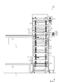
- the side view which shows the inside of the conveyance apparatus.
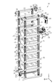
- the perspective view which shows the raising / lowering unit of the conveyance apparatus.
- FIG. The cross-sectional view of the same conveying apparatus.
- the cross-sectional view which shows the state of the press part before extruding an article
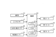
- the block diagram which shows the electric constitution of the conveyance apparatus.
- the transfer device 11 is provided in a multi-story building (two-story in this embodiment), and one floor (for example, the second floor F2) to another floor (for example, the first floor F1).
- the article B is transported.
- the transport device 11 includes a main body 12 that has a vertically long, substantially rectangular parallelepiped shape so as to straddle between a plurality of floors. That is, in this embodiment, the main-body part 12 is provided so that it may straddle between the 1st floor F1 and the 2nd floor F2.
- the main body 12 has a conveyance path 13 in which the article B is conveyed, and the conveyance path 13 extends in the vertical direction.
- the main body 12 has a plurality of exterior panels 14 that are appropriately arranged so as to form front, rear, left, and right outer surfaces.
- an entrance / exit 15 through which the article B can enter and exit the transport passage 13 is provided.
- a roller conveyor 16 that supports the article B that is output from each of the entrances 15 is attached.
- An area sensor 17 as an example of an entry detection unit that detects entry into each entry / exit 15 is provided outside each entry / exit 15 on the front surface of the main body 12.
- the area sensor 17 includes a light projecting unit 18 provided on the left side of the entrance / exit 15 on the front surface of the main body portion 12 and a light receiving unit 19 provided on the right side of the entrance / exit 15 on the front surface of the main body portion 12.
- the light projecting unit 18 has a plurality of light projectors (not shown).
- the light receiving unit 19 has a plurality of light receivers (not shown).
- the plurality of light projectors constituting the light projecting unit 18 are arranged at predetermined intervals in the vertical direction, and the plurality of light receivers constituting the light receiving unit 19 are arranged at predetermined intervals in the vertical direction.
- each light receiver receives the presence or absence of an object depending on whether or not at least one of the plurality of linear lights is blocked. Is detected. That is, the area sensor 17 detects the entry of an object such as a user's hand or a foreign object from the entrance 15.
- an operation unit 20 for operating the transport device 11 is provided beside each area sensor 17 on the front surface of the main body unit 12. That is, the operation unit 20 is provided at a position corresponding to the first floor F1 and the second floor F2 on the front surface of the main body unit 12, respectively. Accordingly, the transport device 11 can be operated from the first floor F1 or the second floor F2.
- an elevating unit 30 for elevating the article B is provided in the main body 12.
- the article B in the present embodiment is configured such that a product is housed in a bottomed rectangular box-like case having an open upper end.
- the elevating unit 30 is disposed at the right end portion of the transport passage 13 and is disposed at the left end portion of the pair of front and rear endless right chains 31 extending in the vertical direction over the entire transport passage 13 and the transport passage 13.
- a pair of front and rear endless left chains 32 extending in the vertical direction is provided.
- the pair of right chains 31 and the pair of left chains 32 are spaced apart in the left-right direction so as to form a pair.
- the pair of right chains 31 and the pair of left chains 32 constitute a moving unit that extends to the transport path 13 and is movable in the transport path 13.
- the lower ends of the pair of right chains 31 are wound around a pair of front and rear right lower sprockets 33 supported by the main body 12 so as to be rotatable around an axis extending in the front and rear direction.
- the upper ends of the pair of right chains 31 are wound around a pair of front and rear upper right sprockets 34 that can rotate around an axis extending in the front and rear direction.
- the pair of front and rear right upper sprockets 34 are supported by a right shaft 35 extending in the front and rear direction so as to rotate integrally with the right shaft 35.
- a right transmission bevel gear 36 is provided at the rear end of the right shaft 35 so as to rotate integrally with the right shaft 35 around an axis extending in the front-rear direction.
- the lower ends of the pair of left chains 32 are wound around a pair of front and rear left lower sprockets 37 supported by the main body 12 so as to be rotatable around an axis extending in the front and rear direction.
- the upper ends of the pair of left chains 32 are wound around a pair of front left and right upper sprockets 38 that can rotate around an axis extending in the front-rear direction.
- the pair of front and rear left upper sprockets 38 are supported on a left shaft 39 extending in the front and rear direction so as to rotate integrally with the left shaft 39.
- a left transmission bevel gear 40 is provided at the rear end of the left shaft 39 so as to rotate integrally with the left shaft 39 around an axis extending in the front-rear direction.
- the right transmission bevel gear 36 is engaged with a right drive bevel gear 42 provided on the drive shaft 41 extending in the left-right direction so as to be integrally rotatable from the right side.
- the left transmission bevel gear 40 is engaged with a left drive bevel gear 43 provided on the drive shaft 41 so as to be integrally rotatable from the left side.
- a first motor 44 that rotationally drives the drive shaft 41 is connected to the right end of the drive shaft 41. Therefore, when the first motor 44 is driven to rotate the drive shaft 41, the rotational force is transmitted to the right shaft 35 and the left shaft 39, respectively, and the right shaft 35 and the left shaft 39 are synchronized with each other in opposite directions. To be rotated.
- the pair of right chains 31 are provided with a plurality of L-shaped support plates 45 extending in the front-rear direction so as to bridge the pair of right chains 31.
- the plurality of support plates 45 are arranged at equal intervals in the longitudinal direction of the pair of right chains 31.
- the pair of left chains 32 is also provided with a plurality of support plates 45 as with the pair of right chains 31.
- the plurality of support plates 45 provided on the pair of right chains 31 and the plurality of support plates 45 provided on the pair of left chains 32 are They are facing each other in the direction.
- the article B can be supported by the support plate 45 on the right chain 31 side and the support plate 45 on the left chain 32 side that face each other in the left-right direction between the pair of right chains 31 and the pair of left chains 32.
- a support portion is configured.
- the article B is horizontally held with its left and right ends supported by a pair of support plates 45 on the right chain 31 side and a support plate 45 on the left chain 32 side.
- the pair of support plates 45 facing in the left-right direction between the pair of right chains 31 and the pair of left chains 32 rises and falls synchronously, thereby maintaining the article B in a horizontal state. It is lifted up and down.
- the pair of support plates 45 is configured to be able to support the three articles B arranged in the front-rear direction.
- a protrusion detection sensor 46 as an example of a protrusion detection unit that detects an article B protruding to the front side from each pair of support plates 45 is provided at the front position in the main body 12.
- the protrusion detection sensor 46 is a so-called mirror reflection type photoelectric sensor.
- the protrusion detection sensor 46 is disposed at the front lower end in the main body 12 and includes a light projecting unit (not shown) and a light receiving unit (not shown).
- a reflection mirror 48 is disposed at the front upper end in the main body 12. The protrusion detection sensor 46 and the reflection mirror 48 are arranged on the same straight line.
- the protrusion detection sensor 46 detects the article B protruding frontward from each pair of support plates 45.
- the protrusion detection sensor 46 may be configured by a so-called transmissive photoelectric sensor in which a light receiving unit is disposed instead of the reflection mirror 48 at a position where the reflection mirror 48 is disposed.
- An article detection sensor 50 as an example of a detection unit is provided.
- an article detection sensor 50 for detecting the article B supported by the pair of support plates 45 arranged at the position corresponding to the position is provided at a position corresponding to the entrance 15 of the second floor F2 in the main body 12. It has been.
- the article detection sensor 50 is constituted by a so-called mirror reflection type photoelectric sensor.
- the article detection sensor 50 is disposed at the left front part in the main body 12 and has a light projecting part (not shown) and a light receiving part (not shown).
- a reflection mirror 51 is arranged at a position corresponding to the first floor F1 in the right rear portion in the main body 12.
- a reflection mirror 51 is disposed at a position corresponding to the second floor F2 in the right rear portion in the main body portion 12. In each of the first floor F1 and the second floor F2, the article detection sensor 50 and the reflection mirror 51 are arranged on the same straight line.
- the light projected from the light projecting part of the article detection sensor 50 is reflected by the reflection mirror 51, and the reflected light is received by the light receiving part of the article detection sensor 50.
- the presence or absence of the article B on the pair of support plates 45 is detected based on whether or not the light at this time is blocked. That is, the article detection sensor 50 arranged at a position corresponding to the entrance / exit 15 of the first floor F1 detects the presence / absence of the article B on the pair of support plates 45 arranged at the position corresponding to the position.
- the article detection sensor 50 arranged at a position corresponding to the entrance / exit 15 of the second floor F2 detects the presence / absence of the article B on the pair of support plates 45 arranged at a position corresponding to the position.
- the linear light projected from the light projecting unit of the article detection sensor 50 is obliquely applied to the article B, there is only one article B on the target pair of support plates 45.
- the article B is detected by the article detection sensor 50 no matter where the article B is arranged on the support plate 45.
- the article detection sensor 50 may be configured by a so-called transmissive photoelectric sensor in which a light receiving unit is disposed instead of the reflection mirror 51 at a position where the reflection mirror 51 is disposed.
- a chain conveyor device 52 is disposed for transporting from the inside to the roller conveyor 16 on the first floor F1 through the entrance 15 on the first floor F1.
- the chain conveyor device 52 is wound around a pair of left and right drive sprockets 53 and a pair of left and right driven sprockets 54, and a pair of drive sprockets 53 and a pair of driven sprockets 54 disposed on the front side and the rear side in the main body portion 12.
- a pair of left and right endless transport chains 55 and a second motor 56 that rotationally drives the drive sprocket 53 are provided.
- the article B is transferred from the pair of support plates 45 onto the pair of transport chains 55.
- the second motor 56 is driven in a state where the article B is disposed on the pair of transport chains 55, the pair of transport chains 55 circulates around the pair of drive sprockets 53 and the pair of driven sprockets 54 so that the article B It is conveyed on the roller conveyor 16 of the first floor F1 through the entrance 15 of the first floor F1.
- the article B supported by the pair of support plates 45 arranged on the second floor F2 is placed on the second floor F2 on the opposite side of the main body 12 from the entrance 15 at a position corresponding to the second floor F2.
- a pressing portion 60 that pushes from the doorway 15 onto the roller conveyor 16 on the second floor F2 provided outside the main body portion 12.
- the pressing portion 60 includes a meshing chain 63, a housing portion 64, and a movable body 65.
- the meshing chain 63 has a pair of chain members 63a and 63b that can mesh with each other and can move forward and backward along its longitudinal direction.
- the accommodating portion 64 is fixed to the main body portion 12.
- the movable body 65 is connected to the tip of the meshing chain 63.
- the accommodating portion 64 is configured to accommodate the meshing chain 63.
- a sprocket 66 capable of rotating in both forward and reverse directions about an axis extending in the vertical direction is provided at the central portion in the left-right direction corresponding to the branching direction in the accommodating portion 64 so as to mesh with the chain member 63a (meshing chain 63). ing.
- the sprocket 66 is rotationally driven in both forward and reverse directions by a third motor 67 (see FIG. 3). As the sprocket 66 is driven to rotate, the meshing chain 63 moves forward and backward along the front-rear direction corresponding to the forward / backward movement direction.
- the housing part 64 includes a rectangular outer casing 68 (see FIG. 3) and a guide plate 69 having a rectangular shape substantially the same as the outer casing 68 in the vertical direction.
- a pair of guide grooves 70 are provided on the inner surface of the guide plate 69 so as to be substantially symmetrical.
- the pair of guide grooves 70 have spiral portions that can guide the pair of chain members 63a and 63b so that the pair of chain members 63a and 63b branched from the meshing state move while spiraling.
- a pair of guide grooves 70 are provided on the inner surface of the exterior 68 so as to correspond to the pair of guide grooves 70 of the guide plate 69. Therefore, a pair of guide grooves 70 and a pair of guide grooves 70 are provided on both inner surfaces in the vertical direction of the accommodating portion 64 so as to face each other.
- An opening 71 for passing the meshing chain 63 is formed in a substantially central portion in the left-right direction of the surface of the accommodating portion 64 on the traveling direction side of the meshing chain 63, that is, the front surface of the accommodating portion 64.
- a portion of the meshing chain 63 exposed from the accommodating portion 64 is covered with a bellows-like cover member 72. The cover member 72 expands and contracts following the forward / backward movement of the meshing chain 63.
- a pair of chain members 63a, 63b constituting the meshing chain 63 is a single row of chain members.
- the pair of chain members 63a and 63b are a plurality of pairs of inner plates 73 as an example of a link member and an example of a link member that are sequentially connected in series in the series direction along these forward and backward movement directions.
- the outer plate 74 is provided.
- the pair of chain members 63a and 63b includes a pair of cylindrical bushes (not shown) assembled between the pair of inner plates 73 facing each other in the vertical direction, and adjacent pairs whose ends overlap in the series direction.
- the inner plate 73 and the outer plate 74 have round bar-like connecting pins 75 that are rotatably connected in series while being inserted through the bush.
- Each inner plate 73 is formed with a pair of inner through holes (not shown) arranged in series.
- Each outer plate 74 is formed with a pair of outer through holes (not shown) arranged in series. The diameter of each outer through hole is set slightly smaller than the diameter of each inner through hole. The end of the bush is inserted into each inner through hole.
- the connecting pin 75 is inserted into each outer through-hole, and the connecting pin 75 is inserted into the bush inserted into each inner through-hole. In this case, both end portions of the connecting pin 75 protrude outward from the outer plate 74 in the vertical direction.
- both end portions of the connecting pin 75 are slidably inserted into the guide grooves 70 provided on the upper and lower inner surfaces of the accommodating portion 64.
- each connecting pin 75 is inserted into the guide groove 70 provided in the guide plate 69 of the accommodating portion 64. Then, the other end is inserted into the guide groove 70 provided in the exterior 68 of the accommodating portion 64.
- the inner plate 73 and the outer plate 74 are formed so as to have the same outline (outer shape), and each have a hook-like claw portion 76. That is, a claw portion 76 is formed at each of the outer plate 74 and the inner plate 73 of the chain member 63a at the end in the traveling direction. A claw portion 76 is formed at each of the outer plate 74 and the inner plate 73 of the chain member 63b at the end portion on the retracting direction side. Therefore, as shown in FIG. 7, the claw portions 76 provided on the outer plate 74 and the inner plate 73 of the chain member 63a and the claw portions 76 provided on the outer plate 74 and the inner plate 73 of the chain member 63b are: They can be engaged with each other.
- the meshing chain 63 has a claw portion of the outer plate 74 corresponding between the pair of chain members 63a and 63b as the pair of chain members 63a and 63b moves forward corresponding to the traveling direction.
- the claw portions 76 of the inner plate 73 and the claw portions 76 of the inner plate 73 are engaged with each other so that a rigid structure integrated in a straight bar shape is obtained.
- the meshing chain 63 is disengaged from each other as the pair of chain members 63a and 63b move rearward corresponding to the retreating direction. It is branched in the direction and accommodated while being mostly wound in the accommodating portion 64.
- the movable body 65 moves together with the meshing chain 63 following the forward / backward movement of the meshing chain 63.
- the transport device 11 includes a control unit 80 that controls the transport device 11 as a whole.
- the control unit 80 includes a CPU 80a, a ROM 80b, and a RAM 80c.
- the CPU 80a functions as a central processing unit and executes various programs.
- the ROM 80b stores various types of information and a conveyance program used for controlling the operation of the entire conveyance device 11 so as to be readable.
- the RAM 80c stores various types of information so that they can be written and read.
- the CPU 80a executes the conveyance program stored in the ROM 80b when various types of information are input via an interface (not shown). As a result, the CPU 80a performs various calculations necessary for controlling the operation of the transport device 11, and reads various information used in the calculations from the ROM 80b or uses them in the calculations. Various kinds of information to be read and written to the RAM 80c.
- the input unit interface (not shown) of the control unit 80 is electrically connected to the operation unit 20, the area sensor 17, the protrusion detection sensor 46, and the article detection sensor 50 for the user to operate.
- the third motor 67, the first motor 44, and the second motor 56 are electrically connected to the output side interface (not shown) of the control unit 80, respectively.
- control unit 80 controls the third motor 67 and the first motor based on the operation of the operation unit 20, the output signal from the area sensor 17, the output signal from the protrusion detection sensor 46, and the output signal from the article detection sensor 50. 44 and the second motor 56 are controlled.
- the transport device 11 when the article B is transported from the first floor F1 to the second floor F2, the user places the article B on the roller conveyor 16 on the first floor F1, and then the main body on the first floor F1.
- the first pair of support plates 45 in the main body 12 arranged at positions corresponding to the entrance 15 of the first floor F1 by sequentially pushing the articles B from the entrance 15 of the section 12. Place.
- the control unit 80 Since the article B is detected by the article detection sensor 50 on the first floor F1, even if the user erroneously lowers the pair of support plates 45 on which the three articles B are placed, the control unit 80 The first motor 44 is not driven. Furthermore, at this time, when an object such as a user's hand or a foreign object is detected by at least one of the two area sensors 17 on the first floor F1 and the second floor F2, the user erroneously operates the operation unit 20 to perform the first operation. Even if the motor 44 is to be driven, the controller 80 does not drive the first motor 44. Further, at this time, when the article B is detected by the protrusion detection sensor 46, the control unit 80 drives the first motor 44 even if the user erroneously operates the operation unit 20 to drive the first motor 44. do not do.
- the user places the three articles B on the second pair of support plates 45 and then operates the operation unit 20 on the first floor F1.
- the next-stage third-stage pair of support plates 45 is moved to the entrance 15 of the first floor F1. Move to the corresponding position.
- the pair of support plates 45 in the first stage is also raised by one stage.
- the first-stage pair of support plates 45 is disposed at a position elevated by two stages from the first floor F1.
- the pair of support plates 45 in the second stage is arranged at a position elevated by one stage from the first floor F1.
- the user operates the operation unit 20 on the first floor F1 after placing the three articles B on the pair of support plates 45 in the third stage.
- the next pair of support plates 45 of the third step is the entrance 15 of the first floor F1.
- the pair of support plates 45 in the first stage and the pair of support plates 45 in the second stage are also raised by one stage.
- the first-stage pair of support plates 45 is arranged at a position elevated by three stages from the first floor F1.
- the pair of support plates 45 in the second stage are arranged at positions that are elevated by two stages from the first floor F1.
- the pair of support plates 45 in the third stage is disposed at a position elevated by one stage from the first floor F1.
- the user places the three articles B on the pair of support plates 45 in the fourth stage, and then operates the operation unit 20 on the first floor F1. Then, when the fourth pair of support plates 45 on which the three articles B are placed are raised by one step, the next pair of support plates 45 of the fourth step is the entrance 15 of the first floor F1. Move to the corresponding position. At this time, the first pair of support plates 45, the second pair of support plates 45, and the third pair of support plates 45 are also raised by one stage. As a result, the first pair of support plates 45 are arranged at positions corresponding to the entrance / exit 15 of the second floor F2, which is a position that rises four steps from the first floor F1.
- the article B is detected by the article detection sensor 50 on the second floor F2.
- the pair of support plates 45 in the second stage is arranged at a position elevated by three stages from the first floor F1.
- the pair of support plates 45 in the third stage are disposed at positions that are elevated by two stages from the first floor F1.
- the pair of support plates 45 in the fourth stage is disposed at a position elevated by one stage from the first floor F1.
- the user places three articles B on the fifth pair of support plates 45 in the same manner as the above-described fourth pair of support plates 45, and then moves to the second floor F2. And if a user operates the operation part 20 of the second floor F2 and drives the 3rd motor 67, the meshing chain 63 of the press part 60 will move ahead corresponding to the advancing direction, as shown in FIG. With this movement, the corresponding claw portions 76 of the outer plate 74 and the corresponding claw portions 76 of the inner plate 73 mesh with each other between the pair of chain members 63a and 63b.
- the user carries the article B pushed onto the roller conveyor 16 on the second floor F2 to a predetermined position. Thereafter, when the user operates the operation unit 20 on the second floor F2 to raise the pair of first support plates 45 after the three articles B are taken out by one step, the next two steps after the first step.
- the pair of support plates 45 of the eyes moves to a position corresponding to the entrance 15 of the second floor F2.
- the article detection sensor 50 on the second floor F2 causes the article detection sensor 50 on the second floor F2. Since the article B remaining on the first pair of support plates 45 is detected, the control unit 80 does not drive the first motor 44. Furthermore, at this time, when an object such as a user's hand or a foreign object is detected by at least one of the two area sensors 17 on the first floor F1 and the second floor F2, the user erroneously operates the operation unit 20 to perform the first operation. Even if the motor 44 is to be driven, the controller 80 does not drive the first motor 44. Further, at this time, when the article B is detected by the protrusion detection sensor 46, even if the user mistakenly operates the operation unit 20 to drive the first motor 44, the control unit 80 causes the first motor 44 to move. Do not drive.
- the user removes the article B on each pair of support plates 45 from the second stage to the fifth stage from the entrance / exit of the second floor F2.
- 15 is sequentially pushed onto the roller conveyor 16 by the pressing unit 60, and the pushed articles B are sequentially carried to a predetermined position.
- the user moves to the first floor F1 and repeats the above-described operation of transporting the article B from the first floor F1 to the second floor F2 until there is no more article B to be transported on the first floor F1.
- the article B for the five stages of the pair of support plates 45 can be stocked between the first floor F1 and the second floor F2 in the main body portion 12, so that the first floor
- the working efficiency can be improved as compared with the case of using a general luggage elevator. That is, when a user carries a large amount of goods B between the first floor F1 and the second floor F2, the user can compare the first floor F1 and the second floor F2 as compared with the case where a general luggage elevator is used.
- the number of reciprocating movements can be significantly reduced.
- the transport device 11 includes a main body 12.
- a pressing portion 60 is provided at a position corresponding to the second floor F ⁇ b> 2 in the main body portion 12.
- the pressing unit 60 pushes the article B supported on the pair of support plates 45 disposed at a position corresponding to the entrance 15 of the second floor F2 from the entrance 15 of the second floor F2 onto the roller conveyor 16 of the second floor F2. Therefore, the article B conveyed from the first floor F1 to the second floor F2 in the main body 12 can be pushed out from the entrance 15 of the second floor F2 to the outside of the main body 12, that is, on the roller conveyor 16 of the second floor F2 by the pressing section 60.
- the article B conveyed from the first floor F1 to the second floor F2 in the main body 12 can be easily taken out from the main body 12 regardless of the form.
- the pressing portion 60 meshes with a meshing chain 63 having a pair of chain members 63 a and 63 b that can move forward and backward, and a housing portion 64 that houses the pair of chain members 63 a and 63 b while winding up.
- a movable body 65 is provided which is connected to the tip of the chain 63 and is movable together with the meshing chain 63 in the forward and backward movement direction of the meshing chain 63. For this reason, when the pair of chain members 63a and 63b are moved and integrated in the advancing direction and the article B is pushed out by the movable body 65 while being integrated, then the pair of chain members 63a and 63b is moved in the backward direction.
- the chain members 63a and 63b are branched and accommodated while being wound around the accommodating portion 64, respectively. That is, the meshing chain 63 is in the shape of a long bar in the use state in which the article B is pushed out, and is housed in the housing portion 64 in a state of being compactly wound in a standby state in which the article B is not pushed out. Therefore, it is possible to contribute to space saving of the pressing unit 60 and, in turn, contribute to space saving of the transport device 11.
- operation units 20 that can operate the entire transport device 11 including the pressing unit 60 are provided at positions corresponding to the first floor F ⁇ b> 1 and the second floor F ⁇ b> 2 in the main body 12. For this reason, operation of the whole conveying apparatus 11 including the press part 60 can be performed from the 1st floor F1 or the 2nd floor F2.
- an area sensor 17 for detecting entry into the entrance / exit 15 is provided outside each entrance / exit 15 in the main body 12. For this reason, for example, when an object such as a foreign object is inserted from the entrance 15, the object can be detected by the area sensor 17. Therefore, the control unit 80 can perform monitoring so that the transport device 11 is not driven in a state where an object such as a foreign object is inserted into the doorway 15.
- a protrusion detection sensor 46 for detecting the article B protruding from the pair of support plates 45 is provided in the main body 12. For this reason, when the article B protrudes from the pair of support plates 45, the article B can be detected by the protrusion detection sensor 46. Therefore, the control unit 80 can perform monitoring so that the conveying device 11 is not driven in a state where the article B protrudes from the pair of support plates 45.
- an article detection sensor 50 that detects the article B supported on the pair of support plates 45 is provided at positions corresponding to the first floor F ⁇ b> 1 and the second floor F ⁇ b> 2 in the main body 12. Yes. For this reason, when the article B is supported by a pair of support plates 45 arranged at positions corresponding to the first floor F1 and the second floor F2, the article B can be detected by the article detection sensor 50. Therefore, the pair of support plates 45 is accidentally lowered while the article B remains on the pair of support plates 45 arranged on the first floor F1, or on the pair of support plates 45 arranged on the second floor F2. Monitoring by the control unit 80 can be performed so that the pair of support plates 45 are not raised accidentally while the article B remains.
- the above embodiment may be modified as follows.
- the article detection sensor 50 may be omitted.
- the pressing portion 60 does not necessarily need to be configured by the meshing chain 63 having a pair of chain members 63a and 63b that can move forward and backward, and may be configured by an actuator such as an air cylinder.
- the transfer device 11 may be configured to correspond to a three-story or higher building.
- one of the three articles B supported on the pair of support plates 45 conveyed from the first floor is taken out on the second floor, and the remaining two articles B are taken out on the third floor. You can also.
- one article B is placed on the third floor and two articles B are placed on the second floor, and then the pair of support plates 45 on which the three articles B are placed. It can also be transported to the first floor.
- the pressing unit 60 and the operation unit 20 are not necessarily provided in the main body unit 12. It is not necessary to provide it at a position corresponding to every floor.
- the pressing part 60 may have two or more pairs of chain members 63a and 63b. Further, the chain members 63a and 63b may be two or more rows of chains. That is, the meshing chain 63 may include, for example, a plurality of pairs of chain members 63a and 63b, or a pair of chain members 63a and 63b each including a plurality of rows of chains.
- a plurality of pressing portions 60 may be provided at positions corresponding to a plurality of floors in the main body 12 of the transport device 11. That is, for example, when the transport device 11 has a configuration corresponding to a three-story building, three pressing portions 60 are provided at positions corresponding to the second floor in the main body 12 and correspond to the third floor in the main body 12. You may make it provide the two press parts 60 in the position to perform. In this way, even when the weight of the article B is large, the article B can be suitably extruded.
- the transport device 11 includes one of the three articles B in which the pressing unit 60 is supported on the pair of support plates 45 by the drive control of the third motor 67 by the control unit 80 based on the operation of the operation unit 20 by the user. Only the article B may be pushed out from the entrance / exit 15, or only two articles B out of the three articles B may be pushed out from the entrance / exit 15. That is, the transport device 11 may be configured to adjust the pressing amount (pressing stroke) of the article B by the pressing unit 60.
Landscapes
- Engineering & Computer Science (AREA)
- Mechanical Engineering (AREA)
- Special Conveying (AREA)
- Control Of Conveyors (AREA)
- Intermediate Stations On Conveyors (AREA)
- Warehouses Or Storage Devices (AREA)
Abstract
搬送装置(11)は、本体部(12)と、チェーン(31,32)と、複数の支持板(45)とを備える。本体部(12)は、一階(F1)及び二階(F2)の間に跨るように延設され、物品(B)が搬送される搬送通路(13)を内部に有している。チェーン(31,32)は、搬送通路(13)に沿って延びるとともに、搬送通路(13)内を移動可能である。複数の支持板(45)は、チェーン(31,32)に当該チェーン(31,32)の長手方向に間隔を置いて設けられ、物品(B)を支持可能である。本体部(12)における複数の階と対応する位置には、搬送通路(13)に対して物品(B)を出入可能な出入口(15)がそれぞれ設けられている。本体部(12)における二階(F2)と対応する位置には押圧部(60)が設けられている。押圧部(60)は、支持板(45)に支持された物品(B)を出入口(15)から本体部(12)の外部へ押し出す。
Description
本発明は、例えば複数階建ての建物の各階間で物品を搬送する搬送装置に関する。
従来、この種の搬送装置としては、例えば特許文献1に示すものが知られている。その搬送装置は、縦長の本体と、複数段となるように当該本体の両側に上下に並ぶように配置された複数対のレールと、各対のレールを上下移動させるエンドレスチェーンとを備えている。各対のレールは、物品が自重で転動するように傾斜して配置されている。
そして、最下段に設けられた物品投入部から物品を投入して一対のレール上にその傾斜上位から傾斜下位に向けて定数の物品を自重で転動させて一列に整列させた後、それらの物品を一対のレールと共に最上段まで上昇させる。その後、最上段の位置で一対のレール上の傾斜上位から傾斜下位に向けて物品を自重で転動させて、それらの物品を物品取出部から取り出すようにしている。
ところで、上述のような搬送装置では、物品を支持する一対のレールの傾斜を利用して物品を自重で転動させることによって取り出すようにしている。このため、物品が転動しない形態であった場合には、ユーザーが物品取出部から物品を手作業で取り出さなければならないので、物品取出部からの物品の取り出し作業が困難になるという問題がある。
本発明は、このような従来技術に存在する問題点に着目してなされたものである。その目的とするところは、搬送した物品をその形態に拘わらず本体部内から容易に取り出すことができる搬送装置を提供することにある。
以下、上記課題を解決するための手段及びその作用効果について記載する。
上記課題を解決する搬送装置は、複数の階のうちの1つの階から他の階へ物品を搬送する搬送装置であって、複数の前記階の間に跨るように延設され、前記物品が搬送される搬送通路を内部に有する本体部と、前記搬送通路に沿って延びるとともに、前記搬送通路内を移動可能な移動部と、前記移動部に当該移動部の長手方向に間隔を置いて設けられ、前記物品を支持可能な複数の支持部と、を備え、前記本体部における複数の前記階と対応する位置には、前記搬送通路に対して前記物品を出入可能な出入口がそれぞれ設けられ、
前記本体部における複数の前記階のうちの少なくとも1つと対応する位置には、前記支持部に支持された前記物品を前記出入口から前記本体部の外部へ押し出す押圧部が設けられている。
上記課題を解決する搬送装置は、複数の階のうちの1つの階から他の階へ物品を搬送する搬送装置であって、複数の前記階の間に跨るように延設され、前記物品が搬送される搬送通路を内部に有する本体部と、前記搬送通路に沿って延びるとともに、前記搬送通路内を移動可能な移動部と、前記移動部に当該移動部の長手方向に間隔を置いて設けられ、前記物品を支持可能な複数の支持部と、を備え、前記本体部における複数の前記階と対応する位置には、前記搬送通路に対して前記物品を出入可能な出入口がそれぞれ設けられ、
前記本体部における複数の前記階のうちの少なくとも1つと対応する位置には、前記支持部に支持された前記物品を前記出入口から前記本体部の外部へ押し出す押圧部が設けられている。
この構成によれば、1つの階から他の階に搬送した物品を押圧部によって出入口から本体部の外部へ押し出すことができるので、搬送した物品をその形態に拘わらず本体部内から容易に取り出すことができる。
上記搬送装置において、前記押圧部は、進退移動可能な少なくとも一対のチェーン部材を有する噛合チェーンであって、各チェーン部材は複数のリンク部材を含み、対をなす前記チェーン部材同士が進行方向に移動することでそれらチェーン部材のリンク部材同士が相互に噛み合って一体化する一方、その一体化した噛合状態から前記チェーン部材同士が退行方向に移動することでそれらチェーン部材のリンク部材同士が相互に噛み外れて分岐する前記噛合チェーンと、相互に噛み外れて分岐したそれぞれの前記チェーン部材を巻き取りながら収容する収容部と、前記噛合チェーンに連結されて前記噛合チェーンとともに前記噛合チェーンの進退移動方向へ移動可能な可動体と、を備えていることが好ましい。
この構成によれば、チェーン部材同士を進行方向に移動させて一体化させながら可動体によって物品を押し出した後、チェーン部材同士を退行方向に移動させると、チェーン部材同士が分岐してそれぞれ収容部に巻き取られながら収容される。このため、押圧部の省スペース化に貢献することができる。
上記搬送装置において、前記本体部における複数の前記階と対応する位置には、少なくとも前記押圧部を操作可能な操作部がそれぞれ設けられていることが好ましい。
この構成によれば、どの階からでも押圧部の操作を行うことができる。
この構成によれば、どの階からでも押圧部の操作を行うことができる。
上記搬送装置において、前記本体部における各出入口の外側には、その出入口への進入を検出する進入検出部が設けられていることが好ましい。
この構成によれば、例えば、出入口から物体が挿入された場合に、当該物体を進入検出部によって検出することができる。
この構成によれば、例えば、出入口から物体が挿入された場合に、当該物体を進入検出部によって検出することができる。
上記搬送装置において、前記本体部内には、前記支持部からはみ出した前記物品を検出するはみ出し検出部が設けられていることが好ましい。
この構成によれば、支持部から物品がはみ出した場合に、当該物品をはみ出し検出部によって検出することができる。
この構成によれば、支持部から物品がはみ出した場合に、当該物品をはみ出し検出部によって検出することができる。
上記搬送装置において、前記本体部内における複数の前記階と対応する位置には、前記支持部に支持された前記物品を検出する物品検出部がそれぞれ設けられていることが好ましい。
この構成によれば、階と対応する位置に配置された支持部に物品が支持されている場合に、当該物品を物品検出部によって検出することができる。
本発明によれば、搬送した物品をその形態に拘わらず本体部内から容易に取り出すことができる。
以下、搬送装置の一実施形態を図面に従って説明する。
図1及び図2に示すように、搬送装置11は、複数階建て(本実施形態では二階建て)の建物に設けられ、1つの階(例えば二階F2)から他の階(例えば一階F1)へ物品Bを搬送するものである。搬送装置11は、複数の階の間に跨るように縦長の略直方体状をなす本体部12を備えている。すなわち、本実施形態において、本体部12は、一階F1と二階F2との間に跨るように設けられている。本体部12は物品Bが搬送される搬送通路13を内部に有しており、搬送通路13は上下方向に延びている。さらに、本体部12は前後左右の各外面を形成するように適宜配設された複数の外装パネル14を有している。
図1及び図2に示すように、搬送装置11は、複数階建て(本実施形態では二階建て)の建物に設けられ、1つの階(例えば二階F2)から他の階(例えば一階F1)へ物品Bを搬送するものである。搬送装置11は、複数の階の間に跨るように縦長の略直方体状をなす本体部12を備えている。すなわち、本実施形態において、本体部12は、一階F1と二階F2との間に跨るように設けられている。本体部12は物品Bが搬送される搬送通路13を内部に有しており、搬送通路13は上下方向に延びている。さらに、本体部12は前後左右の各外面を形成するように適宜配設された複数の外装パネル14を有している。
本体部12における一階F1及び二階F2と対応する位置には、搬送通路13に物品Bを出入可能な出入口15がそれぞれ設けられている。本体部12の前面には、各出入口15から出される物品Bを支持するローラコンベヤ16が取着されている。本体部12の前面における各出入口15の外側には、各出入口15への進入を検出する進入検出部の一例としてのエリアセンサー17が設けられている。
エリアセンサー17は、本体部12の前面における出入口15の左側に設けられた投光ユニット18と、本体部12の前面における出入口15の右側に設けられた受光ユニット19とを備えている。投光ユニット18は複数の投光器(図示略)を有している。受光ユニット19は複数の受光器(図示略)を有している。投光ユニット18を構成する複数の投光器は上下方向に所定の間隔で配置され、受光ユニット19を構成する複数の受光器は上下方向に所定の間隔で配置されている。
そして、各投光器から投光された直線状の光は各受光器で受光され、これら複数の直線状の光のうち少なくとも1本の直線状の光が遮られるか遮られないかで物体の有無を検出する。すなわち、エリアセンサー17は、ユーザーの手や異物などの物体の出入口15からの進入を検出する。
また、本体部12の前面における各エリアセンサー17の横には、搬送装置11を操作するための操作部20が設けられている。すなわち、操作部20は、本体部12の前面における一階F1及び二階F2と対応する位置に、それぞれ設けられている。したがって、搬送装置11は一階F1からでも二階F2からでも操作が可能である。
図2及び図3に示すように、本体部12内には、物品Bを昇降する昇降ユニット30が設けられている。本実施形態における物品Bは、上端が開口した有底矩形箱状のケース内に商品が収容された形態とされている。昇降ユニット30は、搬送通路13の右端部に配置されるとともに搬送通路13全体にわたって上下方向に延びる前後一対の無端状の右チェーン31と、搬送通路13の左端部に配置されるとともに搬送通路13全体にわたって上下方向に延びる前後一対の無端状の左チェーン32とを備えている。
一対の右チェーン31と一対の左チェーン32とは対をなすように左右方向において離れて配置されている。本実施形態では、一対の右チェーン31及び一対の左チェーン32により、搬送通路13に延びるとともに搬送通路13内を移動可能な移動部が構成されている。
一対の右チェーン31の下端部は前後方向に延びる軸線の周りに回動可能に本体部12に支持された前後一対の右下スプロケット33に巻き掛けられている。一対の右チェーン31の上端部は前後方向に延びる軸線の周りに回動可能な前後一対の右上スプロケット34に巻き掛けられている。前後一対の右上スプロケット34は、前後方向に延びる右軸35に、同右軸35と一体に回動するように支持されている。右軸35の後端には、前後方向に延びる軸線の周りに右軸35と一体に回動するように右伝達傘歯車36が設けられている。
一対の左チェーン32の下端部は前後方向に延びる軸線の周りに回動可能に本体部12に支持された前後一対の左下スプロケット37に巻き掛けられている。一対の左チェーン32の上端部は前後方向に延びる軸線の周りに回動可能な前後一対の左上スプロケット38に巻き掛けられている。前後一対の左上スプロケット38は、前後方向に延びる左軸39に、同左軸39と一体に回動するように支持されている。左軸39の後端には、前後方向に延びる軸線の周りに左軸39と一体に回動するように左伝達傘歯車40が設けられている。
右伝達傘歯車36には左右方向に延びる駆動軸41に一体回動可能に設けられた右駆動傘歯車42が右側から噛合している。左伝達傘歯車40には駆動軸41に一体回動可能に設けられた左駆動傘歯車43が左側から噛合している。駆動軸41の右端には、駆動軸41を回転駆動する第1モーター44が接続されている。したがって、第1モーター44を駆動して駆動軸41を回転させると、その回転力が右軸35及び左軸39にそれぞれ伝達されて、右軸35と左軸39とが同期して互いに逆方向に回転される。
一対の右チェーン31には、前後方向に延びる断面視L字状の複数の支持板45が一対の右チェーン31を橋架するように設けられている。複数の支持板45は、一対の右チェーン31の長手方向に等間隔となるように配置されている。一対の左チェーン32にも、一対の右チェーン31と同様に複数の支持板45が設けられている。
一対の右チェーン31と一対の左チェーン32との間において、一対の右チェーン31に設けられた複数の支持板45と、一対の左チェーン32に設けられた複数の支持板45とは、左右方向においてそれぞれ対向している。本実施形態では、一対の右チェーン31と一対の左チェーン32との間で左右方向において対向する右チェーン31側の支持板45と左チェーン32側の支持板45とによって物品Bを支持可能な支持部が構成されている。物品Bは、対をなす右チェーン31側の支持板45と左チェーン32側の支持板45とにより、左右方向の両端部が支持されて水平に保持される。
そして、第1モーター44を駆動して駆動軸41を正回転させたり逆回転させたりすると、その回転力が右軸35及び左軸39にそれぞれ伝達されて、右軸35と左軸39とが同期して互いに逆方向に回転される。これにより、一対の右チェーン31と一対の左チェーン32との間の左右方向で対向する各対の支持板45が同期して上昇したり下降したりすることで、物品Bが水平状態を維持されながら昇降される。なお、本実施形態では、一対の支持板45は、前後方向に並べられた3つの物品Bを支持可能に構成されている。
図4に示すように、本体部12内の前側の位置には、各対の支持板45から前側にはみ出した物品Bを検出するはみ出し検出部の一例としてのはみ出し検出センサー46が設けられている。本実施形態では、はみ出し検出センサー46が所謂ミラー反射型の光電センサーによって構成されている。はみ出し検出センサー46は、本体部12内の前側の下端部に配置され、投光部(図示略)と受光部(図示略)とを有している。本体部12内の前側の上端部には、反射ミラー48が配置されている。はみ出し検出センサー46と反射ミラー48とは同一直線上に配置されている。
そして、はみ出し検出センサー46の投光部から投光された光は反射ミラー48で反射され、その反射光がはみ出し検出センサー46の受光部で受光される。このときの光が遮られるか遮られないかで各対の支持板45からの物品Bのはみ出し有無を検出する。すなわち、はみ出し検出センサー46は、各対の支持板45から前側にはみ出した物品Bを検出する。なお、はみ出し検出センサー46は、反射ミラー48が配置される位置に同反射ミラー48の代わりに受光部を配置する、所謂透過型の光電センサーによって構成してもよい。
図5に示すように、本体部12内における一階F1の出入口15と対応する位置には、当該位置と対応する位置に配置された一対の支持板45に支持された物品Bを検出する物品検出部の一例としての物品検出センサー50が設けられている。同様に、本体部12内における二階F2の出入口15と対応する位置には、当該位置と対応する位置に配置された一対の支持板45に支持された物品Bを検出する物品検出センサー50が設けられている。本実施形態では、物品検出センサー50が所謂ミラー反射型の光電センサーによって構成されている。物品検出センサー50は、本体部12内の左前部に配置され、投光部(図示略)と受光部(図示略)とを有している。本体部12内の右後部における一階F1と対応する位置には、反射ミラー51が配置されている。同様に、本体部12内の右後部における二階F2と対応する位置には、反射ミラー51が配置されている。一階F1及び二階F2の各々において、物品検出センサー50と反射ミラー51とは同一直線上に配置されている。
そして、一階F1及び二階F2の各々において、物品検出センサー50の投光部から投光された光は反射ミラー51で反射され、その反射光が物品検出センサー50の受光部で受光される。このときの光が遮られるか遮られないかで一対の支持板45上の物品Bの有無を検出する。すなわち、一階F1の出入口15に対応する位置に配置された物品検出センサー50は、当該位置と対応する位置に配置された一対の支持板45上の物品Bの有無を検出する。同様に、二階F2の出入口15と対応する位置に配置された物品検出センサー50は、当該位置と対応する位置に配置された一対の支持板45上の物品Bの有無を検出する。この場合、物品検出センサー50の投光部から投光される直線状の光は物品Bに対して斜めに照射されるため、対象となる一対の支持板45上の物品Bが1つしかなく且つその物品Bが支持板45上のどの位置に配置されていても、当該物品Bは物品検出センサー50によって検出される。なお、物品検出センサー50は、反射ミラー51が配置される位置に同反射ミラー51の代わりに受光部を配置する、所謂透過型の光電センサーによって構成してもよい。
図2及び図3に示すように、本体部12内の搬送通路13における一階F1と対応する位置には、一階F1に配置された一対の支持板45から受け取った物品Bを本体部12内から一階F1の出入口15を介して一階F1のローラコンベヤ16上に搬送するチェーンコンベヤ装置52が配置されている。チェーンコンベヤ装置52は、本体部12内の前側及び後側に配置された左右一対の駆動スプロケット53及び左右一対の従動スプロケット54と、一対の駆動スプロケット53及び一対の従動スプロケット54に巻き掛けられた左右一対の無端状の搬送チェーン55と、駆動スプロケット53を回転駆動する第2モーター56とを備えている。
そして、物品Bを支持した一対の支持板45が一対の搬送チェーン55の上端部よりも下側に下がると、一対の支持板45上から一対の搬送チェーン55上に物品Bが移載される。物品Bが一対の搬送チェーン55上に配置された状態で、第2モーター56が駆動されると、一対の搬送チェーン55が一対の駆動スプロケット53及び一対の従動スプロケット54を周回して物品Bが一階F1の出入口15を介して一階F1のローラコンベヤ16上に搬送される。
図2及び図6に示すように、本体部12の二階F2と対応する位置における出入口15とは反対側には、二階F2に配置された一対の支持板45に支持された物品Bを二階F2の出入口15から本体部12の外部に設けられた二階F2のローラコンベヤ16上へ押し出す押圧部60が設けられている。
図6及び図7に示すように、押圧部60は、噛合チェーン63と、収容部64と、可動体65とを備えている。噛合チェーン63は、互いに噛合可能な一対のチェーン部材63a,63bを有するとともにその長手方向に沿って進退移動可能である。収容部64は本体部12に固定されている。可動体65は、噛合チェーン63の先端に連結されている。
収容部64は、噛合チェーン63を収容可能に構成されている。収容部64内における分岐方向に対応する左右方向の中央部には、上下方向に延びる軸線の周りに正逆両方向に回転可能なスプロケット66がチェーン部材63a(噛合チェーン63)と噛み合うように設けられている。スプロケット66は、第3モーター67(図3参照)によって正逆両方向に回転駆動される。そして、このスプロケット66の回転駆動に伴って噛合チェーン63は進退移動方向に対応する前後方向に沿って進退移動する。
収容部64は、矩形状の外装68(図3参照)と、上下方向において外装68と略同一の矩形状をなす誘導板69とを備えている。誘導板69の内面には、一対の誘導溝70がほぼ左右対称となるように設けられている。一対の誘導溝70は、噛合状態から分岐した一対のチェーン部材63a,63bが渦巻きながら移動するように、一対のチェーン部材63a,63bを誘導可能な渦巻状の部分を有している。
また、収容部64において、外装68の内面には、誘導板69の一対の誘導溝70と対応するように一対の誘導溝70が設けられている。したがって、収容部64の上下方向における両内面には、一対の誘導溝70と一対の誘導溝70とが対向するように設けられている。収容部64における噛合チェーン63の進行方向側の面、すなわち収容部64における前側の面における左右方向のほぼ中央部には、噛合チェーン63を通すための開口部71が形成されている。噛合チェーン63における収容部64から露出した部分は蛇腹状のカバー部材72によって覆われている。カバー部材72は噛合チェーン63の進退移動に追随して伸縮する。
本実施形態において、噛合チェーン63を構成する一対のチェーン部材63a,63bには、一列のチェーン部材が採用されている。そして、一対のチェーン部材63a,63bは、これらの進退移動方向に沿った直列方向へ順次に直列に連結されるリンク部材の一例としての複数対の内プレート73とリンク部材の一例としての複数対の外プレート74とをそれぞれ有している。
さらに、一対のチェーン部材63a,63bは、上下方向において対向する各対の内プレート73の間に組み付けられる円筒状のブシュ(図示略)と、直列方向において端部同士が重なって隣り合う各対の内プレート73と外プレート74とをブシュに挿通された状態で回動自在に直列に連結する丸棒状の連結ピン75とを有している。
各内プレート73には直列方向に並ぶ一対の内貫通孔(図示略)が形成されている。各外プレート74には直列方向に並ぶ一対の外貫通孔(図示略)が形成されている。各外貫通孔の径は各内貫通孔の径よりも若干小さく設定されている。各内貫通孔にはブシュの端部が挿嵌される。
各外貫通孔には連結ピン75が挿嵌され、各内貫通孔に挿嵌されたブシュには連結ピン75が挿通される。この場合、連結ピン75の両端部は、上下方向において外プレート74よりも外側に突出している。一対のチェーン部材63a,63bが収容部64内に収容される際には、連結ピン75の両端部が収容部64の上下両内面に設けられた誘導溝70に摺動可能に挿入される。
すなわち、一対のチェーン部材63a,63bが収容部64内に巻き取られながら収容される際には、各連結ピン75の一端部が収容部64の誘導板69に設けられた誘導溝70に挿入され、他端部が収容部64の外装68に設けられた誘導溝70に挿入される。
内プレート73及び外プレート74は、互いに同じ輪郭(外形)を有するように形成されており、鉤状の爪部76をそれぞれ有している。すなわち、チェーン部材63aの各外プレート74及び各内プレート73における進行方向側の端部には、爪部76がそれぞれ形成されている。チェーン部材63bの各外プレート74及び各内プレート73における退行方向側の端部には、爪部76がそれぞれ形成されている。したがって、図7に示すように、チェーン部材63aの外プレート74及び内プレート73に設けられた爪部76と、チェーン部材63bの外プレート74及び内プレート73に設けられた爪部76とは、互いに噛合可能である。
噛合チェーン63は、図8に示すように、一対のチェーン部材63a,63bの進行方向に対応する前方への移動に伴って一対のチェーン部材63a,63bの間で対応する外プレート74の爪部76同士及び内プレート73の爪部76同士がそれぞれ相互に噛み合うことで直棒状に一体化した剛体構造の噛合状態となる。一方、噛合チェーン63は、図6に示すように、その噛合状態から一対のチェーン部材63a,63bの退行方向に対応する後方への移動に伴って相互に噛み外れることで分岐方向に対応する左右方向に分岐されて大部分が収容部64内に巻き取られながら収容される。可動体65は、噛合チェーン63の進退移動に追随して噛合チェーン63と共に移動する。
次に、搬送装置11の電気的構成について説明する。
図9に示すように、搬送装置11は、搬送装置11全体を統括的に制御する制御部80を備えている。制御部80は、CPU80a、ROM80b、及びRAM80cを備えている。CPU80aは、中央処理装置として機能し、各種のプログラムを実行する。ROM80bは、各種の情報や搬送装置11全体の動作を制御するために用いられる搬送用プログラム等を読み出し可能に記憶する。RAM80cは、各種の情報を書き込み及び読み出し可能に記憶する。
図9に示すように、搬送装置11は、搬送装置11全体を統括的に制御する制御部80を備えている。制御部80は、CPU80a、ROM80b、及びRAM80cを備えている。CPU80aは、中央処理装置として機能し、各種のプログラムを実行する。ROM80bは、各種の情報や搬送装置11全体の動作を制御するために用いられる搬送用プログラム等を読み出し可能に記憶する。RAM80cは、各種の情報を書き込み及び読み出し可能に記憶する。
CPU80aは、図示しないインターフェースを介して各種の情報が入力された場合、ROM80bに記憶された搬送用プログラムを実行する。これにより、CPU80aは、搬送装置11の動作を制御するために必要とされる各種の演算を行うと共に、その演算において使用される各種の情報の読み出しをROM80bに対して行ったり、その演算において使用される各種の情報の読み出し及び書き込みをRAM80cに対して行ったりする。
制御部80の入力側インターフェース(図示略)には、ユーザーが操作するための操作部20、エリアセンサー17、はみ出し検出センサー46、及び物品検出センサー50がそれぞれ電気的に接続されている。制御部80の出力側インターフェース(図示略)には、第3モーター67、第1モーター44、及び第2モーター56がそれぞれ電気的に接続されている。
そして、制御部80は、操作部20の操作、エリアセンサー17からの出力信号、はみ出し検出センサー46からの出力信号、及び物品検出センサー50からの出力信号に基づき、第3モーター67、第1モーター44、及び第2モーター56の駆動をそれぞれ制御する。
次に、搬送装置11の作用について説明する。
図1及び図2に示すように、一階F1から物品Bを二階F2に搬送する場合には、ユーザーが一階F1のローラコンベヤ16上に物品Bを載置してから一階F1における本体部12の出入口15から物品Bを順次に押し込んで、一階F1の出入口15と対応する位置に配置された本体部12内の1段目の一対の支持板45上に例えば3つの物品Bを載置する。続いて、ユーザーが一階F1の操作部20を操作して、3つの物品Bが載置された1段目の一対の支持板45を一段分だけ上昇させると、1段目の次の2段目の一対の支持板45が一階F1の出入口15と対応する位置に移動する。
図1及び図2に示すように、一階F1から物品Bを二階F2に搬送する場合には、ユーザーが一階F1のローラコンベヤ16上に物品Bを載置してから一階F1における本体部12の出入口15から物品Bを順次に押し込んで、一階F1の出入口15と対応する位置に配置された本体部12内の1段目の一対の支持板45上に例えば3つの物品Bを載置する。続いて、ユーザーが一階F1の操作部20を操作して、3つの物品Bが載置された1段目の一対の支持板45を一段分だけ上昇させると、1段目の次の2段目の一対の支持板45が一階F1の出入口15と対応する位置に移動する。
このとき、一階F1の物品検出センサー50によって物品Bが検出されているため、3つの物品Bが載置された一対の支持板45をユーザーが誤って下降させようとしても、制御部80は第1モーター44を駆動しない。さらにこのとき、一階F1及び二階F2の2つのエリアセンサー17のうちの少なくとも一方によってユーザーの手や異物などの物体が検出されている場合、ユーザーが誤って操作部20を操作して第1モーター44を駆動させようとしても、制御部80は第1モーター44を駆動しない。さらにこのとき、はみ出し検出センサー46によって物品Bが検出されている場合、ユーザーが誤って操作部20を操作して第1モーター44を駆動させようとしても、制御部80は第1モーター44を駆動しない。
続いて、上述の1段目の一対の支持板45と同様に、ユーザーが2段目の一対の支持板45上に3つの物品Bを載置してから一階F1の操作部20を操作して3つの物品Bが載置された2段目の一対の支持板45を一段分だけ上昇させると、2段目の次の3段目の一対の支持板45が一階F1の出入口15と対応する位置に移動する。このとき、1段目の一対の支持板45も一段分だけ上昇する。その結果、1段目の一対の支持板45は、一階F1から二段分上昇した位置に配置される。2段目の一対の支持板45は一階F1から一段分上昇した位置に配置される。
続いて、上述の2段目の一対の支持板45と同様に、ユーザーが3段目の一対の支持板45上に3つの物品Bを載置してから一階F1の操作部20を操作して3つの物品Bが載置された3段目の一対の支持板45を一段分だけ上昇させると、3段目の次の4段目の一対の支持板45が一階F1の出入口15と対応する位置に移動する。このとき、1段目の一対の支持板45及び2段目の一対の支持板45も一段分だけそれぞれ上昇する。その結果、1段目の一対の支持板45は、一階F1から三段分上昇した位置に配置される。2段目の一対の支持板45は一階F1から二段分上昇した位置に配置される。3段目の一対の支持板45は一階F1から一段分上昇した位置に配置される。
続いて、上述の3段目の一対の支持板45と同様に、ユーザーが4段目の一対の支持板45上に3つの物品Bを載置してから一階F1の操作部20を操作して3つの物品Bが載置された4段目の一対の支持板45を一段分だけ上昇させると、4段目の次の5段目の一対の支持板45が一階F1の出入口15と対応する位置に移動する。このとき、1段目の一対の支持板45、2段目の一対の支持板45、及び3段目の一対の支持板45も一段分だけそれぞれ上昇する。その結果、1段目の一対の支持板45は一階F1から四段分上昇した位置である二階F2の出入口15と対応する位置に配置され、この1段目の一対の支持板45上の物品Bが二階F2の物品検出センサー50によって検出される。2段目の一対の支持板45は一階F1から三段分上昇した位置に配置される。3段目の一対の支持板45は一階F1から二段分上昇した位置に配置される。4段目の一対の支持板45は一階F1から一段分上昇した位置に配置される。
続いて、ユーザーは、上述の4段目の一対の支持板45と同様にして5段目の一対の支持板45上に3つの物品Bを載置した後、二階F2へ移動する。そして、ユーザーが二階F2の操作部20を操作して第3モーター67を駆動させると、押圧部60の噛合チェーン63は、図8に示すように、進行方向に対応する前方へ移動する。この移動に伴って、一対のチェーン部材63a,63bの間で対応する外プレート74の爪部76同士及び内プレート73の爪部76同士がそれぞれ相互に噛み合う。
これにより、噛合チェーン63が直棒状に一体化した剛体構造の噛合状態となるとともに可動体65が噛合チェーン63の前方への移動に追随して前方へ移動する。すると、可動体65によって、二階F2に配置された1段目の一対の支持板45上に支持された物品Bが二階F2の出入口15から本体部12の外部に設けられた二階F2のローラコンベヤ16上へ押し出される。その後、噛合チェーン63は、図6に示すように、その噛合状態から一対のチェーン部材63a,63bの退行方向に対応する後方への移動に伴って相互に噛み外れることで分岐方向に対応する左右方向に分岐される。そして、噛合チェーン63は、その大部分が収容部64内に巻き取られながら収容される。
続いて、ユーザーは二階F2のローラコンベヤ16上に押し出された物品Bを所定の位置へ運ぶ。その後、ユーザーが二階F2の操作部20を操作して、3つの物品Bが取り出された後の1段目の一対の支持板45を一段分だけ上昇させると、1段目の次の2段目の一対の支持板45が二階F2の出入口15と対応する位置に移動する。
このとき、1段目の一対の支持板45上に物品Bが残っている状態で1段目の一対の支持板45をユーザーが誤って上昇させようとしても、二階F2の物品検出センサー50によって1段目の一対の支持板45上に残っている物品Bが検出されるため、制御部80は第1モーター44を駆動しない。さらにこのとき、一階F1及び二階F2の2つのエリアセンサー17のうちの少なくとも一方によってユーザーの手や異物などの物体が検出されている場合、ユーザーが誤って操作部20を操作して第1モーター44を駆動させようとしても、制御部80は第1モーター44を駆動しない。またさらにこのとき、はみ出し検出センサー46によって物品Bが検出されている場合、ユーザーが誤って操作部20を操作して第1モーター44を駆動させようとしても、制御部80は第1モーター44を駆動しない。
続いて、上述の1段目の一対の支持板45上の物品Bと同様にして、ユーザーは、2段目から5段目までの各対の支持板45上の物品Bを二階F2の出入口15から押圧部60によってローラコンベヤ16上に順次に押し出し、その押し出された物品Bを順次に所定の位置へ運ぶ。その後、ユーザーは一階F1へ移動して、一階F1にある搬送すべき物品Bがなくなるまで物品Bを一階F1から二階F2に搬送する上述の作業を繰り返し行う。
なお、二階F2から物品Bを一階F1に搬送する場合には、物品Bを一階F1から二階F2に搬送する場合の上述の作業と逆の作業を行えばよい。この場合、一階F1の出入口15と対応する位置に移動した一対の支持板45上の物品Bは、チェーンコンベヤ装置52によって一階F1の出入口15からローラコンベヤ16上に搬送される。
このように、本実施形態の搬送装置11では、本体部12内における一階F1と二階F2との間で一対の支持板45の5段分の物品Bをストックすることができるので、一階F1と二階F2との間でユーザーが一人で大量の物品Bを搬送する際に、一般的な荷物用エレベーターを使用する場合に比べて、作業効率を向上することができる。すなわち、一階F1と二階F2との間でユーザーが一人で大量の物品Bを搬送する際に、一般的な荷物用エレベーターを使用する場合に比べて、ユーザーが一階F1と二階F2との間で往復移動する回数を格段に低減することができる。
以上詳述した実施形態によれば、次のような効果が発揮される。
(1)搬送装置11は本体部12を備える。本体部12における二階F2と対応する位置には押圧部60が設けられている。押圧部60は、二階F2の出入口15と対応する位置に配置された一対の支持板45上に支持された物品Bを二階F2の出入口15から二階F2のローラコンベヤ16上へ押し出す。このため、本体部12内を一階F1から二階F2に搬送した物品Bを押圧部60によって二階F2の出入口15から本体部12の外部、すなわち二階F2のローラコンベヤ16上へ押し出すことができるので、本体部12内を一階F1から二階F2に搬送した物品Bをその形態に拘わらず本体部12内から容易に取り出すことができる。
(1)搬送装置11は本体部12を備える。本体部12における二階F2と対応する位置には押圧部60が設けられている。押圧部60は、二階F2の出入口15と対応する位置に配置された一対の支持板45上に支持された物品Bを二階F2の出入口15から二階F2のローラコンベヤ16上へ押し出す。このため、本体部12内を一階F1から二階F2に搬送した物品Bを押圧部60によって二階F2の出入口15から本体部12の外部、すなわち二階F2のローラコンベヤ16上へ押し出すことができるので、本体部12内を一階F1から二階F2に搬送した物品Bをその形態に拘わらず本体部12内から容易に取り出すことができる。
(2)搬送装置11において、押圧部60は、進退移動可能な一対のチェーン部材63a,63bを有する噛合チェーン63と、一対のチェーン部材63a,63bを巻き取りながら収容する収容部64と、噛合チェーン63の先端に連結されて噛合チェーン63とともに噛合チェーン63の進退移動方向へ移動可能な可動体65とを備えている。このため、一対のチェーン部材63a,63b同士を進行方向に移動させて一体化させながら可動体65によって物品Bを押し出した後、一対のチェーン部材63a,63b同士を退行方向に移動させると、一対のチェーン部材63a,63b同士が分岐してそれぞれ収容部64に巻き取られながら収容される。つまり、噛合チェーン63は、物品Bを押し出す使用状態では長尺棒状になり、物品Bを押し出さない待機状態ではコンパクトに巻き取られた状態で収容部64内に収容される。したがって、押圧部60の省スペース化に貢献することができ、ひいては搬送装置11の省スペース化に貢献することができる。
(3)搬送装置11において、本体部12における一階F1及び二階F2と対応する位置には、押圧部60を含む搬送装置11全体を操作可能な操作部20がそれぞれ設けられている。このため、一階F1からでも二階F2からでも押圧部60を含む搬送装置11全体の操作を行うことができる。
(4)搬送装置11において、本体部12における各出入口15の外側には、その出入口15への進入を検出するエリアセンサー17が設けられている。このため、例えば、出入口15から異物などの物体が挿入された場合に、当該物体をエリアセンサー17によって検出することができる。したがって、出入口15に異物などの物体が挿入された状態で搬送装置11が駆動されないように、制御部80による監視を行うことができる。
(5)搬送装置11において、本体部12内には、各対の支持板45上からはみ出した物品Bを検出するはみ出し検出センサー46が設けられている。このため、各対の支持板45上から物品Bがはみ出した場合に、当該物品Bをはみ出し検出センサー46によって検出することができる。したがって、各対の支持板45上から物品Bがはみ出した状態で搬送装置11が駆動されないように、制御部80による監視を行うことができる。
(6)搬送装置11において、本体部12内における一階F1及び二階F2と対応する位置には、一対の支持板45上に支持された物品Bを検出する物品検出センサー50がそれぞれ設けられている。このため、一階F1及び二階F2と対応する位置に配置された一対の支持板45に物品Bが支持されている場合に、当該物品Bを物品検出センサー50によって検出することができる。したがって、一階F1に配置された一対の支持板45上に物品Bが残っている状態で当該一対の支持板45が誤って下降されたり、二階F2に配置された一対の支持板45上に物品Bが残っている状態で当該一対の支持板45が誤って上昇されたりしないように、制御部80による監視を行うことができる。
(変更例)
上記実施形態は次のように変更してもよい。
・物品検出センサー50は省略してもよい。
上記実施形態は次のように変更してもよい。
・物品検出センサー50は省略してもよい。
・はみ出し検出センサー46は省略してもよい。
・エリアセンサー17は省略してもよい。
・押圧部60は、必ずしも進退移動可能な一対のチェーン部材63a,63bを有する噛合チェーン63によって構成する必要はなく、例えばエアシリンダーなどのアクチュエーターによって構成してもよい。
・エリアセンサー17は省略してもよい。
・押圧部60は、必ずしも進退移動可能な一対のチェーン部材63a,63bを有する噛合チェーン63によって構成する必要はなく、例えばエアシリンダーなどのアクチュエーターによって構成してもよい。
・搬送装置11は、三階建て以上の建物に対応するように構成してもよい。このようにすれば、例えば一階から搬送される一対の支持板45上に支持された3つの物品Bのうちの1つの物品Bを二階で取り出し、残りの2つの物品Bを三階で取り出すこともできる。あるいは、一対の支持板45上に、三階で1つの物品Bを載置するとともに二階で2つの物品Bを載置してから当該3つの物品Bが載置された一対の支持板45を一階に搬送するようにすることもできる。この場合、搬送装置11の本体部12における三階以上の階と対応する位置にも押圧部60及び操作部20をそれぞれ設けることが好ましいが、押圧部60及び操作部20は必ずしも本体部12における全ての階と対応する位置に設ける必要はない。
・押圧部60は、二対以上の複数対のチェーン部材63a,63bを有するものであってもよい。また、チェーン部材63a,63bは、二列以上の複数列のチェーンであってもよい。つまり、噛合チェーン63は、例えば、複数対のチェーン部材63a,63bを有するものであってもよいし、各々複数列のチェーンからなるチェーン部材63a,63bを一対有するものであってもよい。
・搬送装置11の本体部12における複数の階と対応する位置に、複数の押圧部60をそれぞれ設けるようにしてもよい。すなわち、例えば搬送装置11が三階建ての建物に対応する構成であった場合には、本体部12における二階と対応する位置に3つの押圧部60を設け、且つ本体部12における三階と対応する位置に2つの押圧部60を設けるようにしてもよい。このようにすれば、物品Bの重量が大きい場合でも物品Bを好適に押し出すことができる。
・搬送装置11は、ユーザーによる操作部20の操作に基づく制御部80による第3モーター67の駆動制御によって押圧部60が一対の支持板45上に支持された3つの物品Bのうちの1つの物品Bだけを出入口15から押し出したり、3つの物品Bのうちの2つの物品Bだけを出入口15から押し出したりすることが可能に構成してもよい。すなわち、搬送装置11は、押圧部60による物品Bの押圧量(押圧ストローク)を調節できるように構成してもよい。
・搬送装置11において、チェーンコンベヤ装置52の代わりに押圧部60を用いてもよい。
11…搬送装置、12…本体部、13…搬送通路、15…出入口、17…進入検出部の一例としてのエリアセンサー、20…操作部、31…移動部を構成する一対の右チェーン、32…移動部を構成する一対の左チェーン、45…支持部を構成する支持板、46…はみ出し検出部の一例としてのはみ出し検出センサー、50…物品検出部の一例としての物品検出センサー、60…押圧部、63…噛合チェーン、63a,63b…チェーン部材、64…収容部、65…可動体、73…リンク部材の一例としての内プレート、74…リンク部材の一例としての外プレート、B…物品、F1…一階、F2…二階。
Claims (6)
- 複数の階のうちの1つの階から他の階へ物品を搬送する搬送装置であって、
複数の前記階の間に跨るように延設され、前記物品が搬送される搬送通路を内部に有する本体部と、
前記搬送通路に沿って延びるとともに、前記搬送通路内を移動可能な移動部と、
前記移動部に当該移動部の長手方向に間隔を置いて設けられ、前記物品を支持可能な複数の支持部と、
を備え、
前記本体部における複数の前記階と対応する位置には、前記搬送通路に対して前記物品を出入可能な出入口がそれぞれ設けられ、
前記本体部における複数の前記階のうちの少なくとも1つと対応する位置には、前記支持部に支持された前記物品を前記出入口から前記本体部の外部へ押し出す押圧部が設けられていることを特徴とする搬送装置。 - 前記押圧部は、
進退移動可能な少なくとも一対のチェーン部材を有する噛合チェーンであって、各チェーン部材は複数のリンク部材を含み、対をなす前記チェーン部材同士が進行方向に移動することでそれらチェーン部材のリンク部材同士が相互に噛み合って一体化する一方、その一体化した噛合状態から前記チェーン部材同士が退行方向に移動することでそれらチェーン部材のリンク部材同士が相互に噛み外れて分岐する前記噛合チェーンと、
相互に噛み外れて分岐したそれぞれの前記チェーン部材を巻き取りながら収容する収容部と、
前記噛合チェーンに連結されて前記噛合チェーンとともに前記噛合チェーンの進退移動方向へ移動可能な可動体と、
を備えていることを特徴とする請求項1に記載の搬送装置。 - 前記本体部における複数の前記階と対応する位置には、少なくとも前記押圧部を操作可能な操作部がそれぞれ設けられていることを特徴とする請求項1または請求項2に記載の搬送装置。
- 前記本体部における各出入口の外側には、その出入口への進入を検出する進入検出部が設けられていることを特徴とする請求項1~請求項3のうちいずれか一項に記載の搬送装置。
- 前記本体部内には、前記支持部からはみ出した前記物品を検出するはみ出し検出部が設けられていることを特徴とする請求項1~請求項4のうちいずれか一項に記載の搬送装置。
- 前記本体部内における複数の前記階と対応する位置には、前記支持部に支持された前記物品を検出する物品検出部がそれぞれ設けられていることを特徴とする請求項1~請求項5のうちいずれか一項に記載の搬送装置。
Applications Claiming Priority (2)
| Application Number | Priority Date | Filing Date | Title |
|---|---|---|---|
| JP2016021125A JP6471706B2 (ja) | 2016-02-05 | 2016-02-05 | 搬送装置 |
| JP2016-021125 | 2016-02-05 |
Publications (1)
| Publication Number | Publication Date |
|---|---|
| WO2017135374A1 true WO2017135374A1 (ja) | 2017-08-10 |
Family
ID=59500870
Family Applications (1)
| Application Number | Title | Priority Date | Filing Date |
|---|---|---|---|
| PCT/JP2017/003800 Ceased WO2017135374A1 (ja) | 2016-02-05 | 2017-02-02 | 搬送装置 |
Country Status (2)
| Country | Link |
|---|---|
| JP (1) | JP6471706B2 (ja) |
| WO (1) | WO2017135374A1 (ja) |
Cited By (2)
| Publication number | Priority date | Publication date | Assignee | Title |
|---|---|---|---|---|
| CN109732387A (zh) * | 2019-03-15 | 2019-05-10 | 嘉兴市台嘉机械有限公司 | 一种智能料仓设备 |
| CN116835289A (zh) * | 2023-07-13 | 2023-10-03 | 河海大学 | 一种纵向分流的自动化生产线 |
Citations (7)
| Publication number | Priority date | Publication date | Assignee | Title |
|---|---|---|---|---|
| JPS567823A (en) * | 1979-06-26 | 1981-01-27 | Yoshida Sharyo Kiki Kk | Automatic controller for loading and unloading of good |
| JPS6469408A (en) * | 1987-09-11 | 1989-03-15 | Okamura Corp | Vertical rotary rack device provided with load pusher |
| JPH03106721A (ja) * | 1989-09-21 | 1991-05-07 | Mitsubishi Electric Corp | 縦型ウエーハ搬送装置 |
| JPH05162855A (ja) * | 1991-04-30 | 1993-06-29 | Iseki & Co Ltd | 苗箱のリフトアップ装置 |
| JPH11301835A (ja) * | 1998-04-21 | 1999-11-02 | Honda Motor Co Ltd | 物品搬送システムにおける物品と人の識別方法及び識別装置ならびに物品搬送システム |
| JP2004123278A (ja) * | 2002-10-01 | 2004-04-22 | Okamura Corp | 荷の昇降移載装置 |
| JP2014015294A (ja) * | 2012-07-09 | 2014-01-30 | Tsubakimoto Chain Co | 噛合チェーン式進退作動装置 |
-
2016
- 2016-02-05 JP JP2016021125A patent/JP6471706B2/ja active Active
-
2017
- 2017-02-02 WO PCT/JP2017/003800 patent/WO2017135374A1/ja not_active Ceased
Patent Citations (7)
| Publication number | Priority date | Publication date | Assignee | Title |
|---|---|---|---|---|
| JPS567823A (en) * | 1979-06-26 | 1981-01-27 | Yoshida Sharyo Kiki Kk | Automatic controller for loading and unloading of good |
| JPS6469408A (en) * | 1987-09-11 | 1989-03-15 | Okamura Corp | Vertical rotary rack device provided with load pusher |
| JPH03106721A (ja) * | 1989-09-21 | 1991-05-07 | Mitsubishi Electric Corp | 縦型ウエーハ搬送装置 |
| JPH05162855A (ja) * | 1991-04-30 | 1993-06-29 | Iseki & Co Ltd | 苗箱のリフトアップ装置 |
| JPH11301835A (ja) * | 1998-04-21 | 1999-11-02 | Honda Motor Co Ltd | 物品搬送システムにおける物品と人の識別方法及び識別装置ならびに物品搬送システム |
| JP2004123278A (ja) * | 2002-10-01 | 2004-04-22 | Okamura Corp | 荷の昇降移載装置 |
| JP2014015294A (ja) * | 2012-07-09 | 2014-01-30 | Tsubakimoto Chain Co | 噛合チェーン式進退作動装置 |
Cited By (2)
| Publication number | Priority date | Publication date | Assignee | Title |
|---|---|---|---|---|
| CN109732387A (zh) * | 2019-03-15 | 2019-05-10 | 嘉兴市台嘉机械有限公司 | 一种智能料仓设备 |
| CN116835289A (zh) * | 2023-07-13 | 2023-10-03 | 河海大学 | 一种纵向分流的自动化生产线 |
Also Published As
| Publication number | Publication date |
|---|---|
| JP2017137189A (ja) | 2017-08-10 |
| JP6471706B2 (ja) | 2019-02-20 |
Similar Documents
| Publication | Publication Date | Title |
|---|---|---|
| EP2634117B1 (en) | Extendable conveyor with modular front end | |
| CN112678392B (zh) | 上料控制方法、控制装置、上料装置及仓储系统 | |
| TW202225062A (zh) | 貨物裝卸控制方法、控制裝置、貨物裝卸裝置及倉儲系統 | |
| US20210403236A1 (en) | Warehouse system | |
| JP6471706B2 (ja) | 搬送装置 | |
| JP2005280868A (ja) | コンベヤにおける搬送物の方向転換方法及び装置 | |
| US9834385B2 (en) | Truck transporting device | |
| JP7061030B2 (ja) | 状態監視装置と状態監視方法 | |
| JP2007126258A (ja) | 物品移載装置及び物品収納設備 | |
| JP2009127197A (ja) | 垂直循環式駐車装置の車両位置検出装置 | |
| JP4855865B2 (ja) | 荷移載装置及び荷移載方法 | |
| JP5781772B2 (ja) | 自動倉庫 | |
| JP4968508B2 (ja) | 物品保管装置 | |
| EP3079846A1 (en) | Bar feeding device | |
| JP7511896B2 (ja) | パレット利用の荷搬送装置 | |
| JP7406238B2 (ja) | 荷搬出入装置 | |
| JPS61252054A (ja) | パレツト移載装置 | |
| CN219648140U (zh) | 一种带弧面物体的自动化检测装置 | |
| CN116891089B (zh) | 一种医院物流系统、医用物流站点及其使用方法 | |
| JP2002347905A (ja) | フリクションローラ駆動パレット移送装置 | |
| JP2003072926A (ja) | スパイラルコンベヤ | |
| IT7354694A1 (it) | Dispositivo di trasferimento di carichi in particolare di autoveicoli | |
| JP5863516B2 (ja) | 自動倉庫 | |
| JP3576519B2 (ja) | 機械式駐車装置の制御装置 | |
| JP5024150B2 (ja) | 機械式駐車場の駐車室・パレットの検査方法 |
Legal Events
| Date | Code | Title | Description |
|---|---|---|---|
| 121 | Ep: the epo has been informed by wipo that ep was designated in this application |
Ref document number: 17747525 Country of ref document: EP Kind code of ref document: A1 |
|
| NENP | Non-entry into the national phase |
Ref country code: DE |
|
| 122 | Ep: pct application non-entry in european phase |
Ref document number: 17747525 Country of ref document: EP Kind code of ref document: A1 |