WO2017135023A1 - 塗工装置 - Google Patents
塗工装置 Download PDFInfo
- Publication number
- WO2017135023A1 WO2017135023A1 PCT/JP2017/001294 JP2017001294W WO2017135023A1 WO 2017135023 A1 WO2017135023 A1 WO 2017135023A1 JP 2017001294 W JP2017001294 W JP 2017001294W WO 2017135023 A1 WO2017135023 A1 WO 2017135023A1
- Authority
- WO
- WIPO (PCT)
- Prior art keywords
- flow path
- coating liquid
- coating
- slit
- die
- Prior art date
- Legal status (The legal status is an assumption and is not a legal conclusion. Google has not performed a legal analysis and makes no representation as to the accuracy of the status listed.)
- Ceased
Links
Images




Classifications
-
- B—PERFORMING OPERATIONS; TRANSPORTING
- B05—SPRAYING OR ATOMISING IN GENERAL; APPLYING FLUENT MATERIALS TO SURFACES, IN GENERAL
- B05C—APPARATUS FOR APPLYING FLUENT MATERIALS TO SURFACES, IN GENERAL
- B05C5/00—Apparatus in which liquid or other fluent material is projected, poured or allowed to flow on to the surface of the work
- B05C5/02—Apparatus in which liquid or other fluent material is projected, poured or allowed to flow on to the surface of the work the liquid or other fluent material being discharged through an outlet orifice by pressure, e.g. from an outlet device in contact or almost in contact, with the work
-
- B—PERFORMING OPERATIONS; TRANSPORTING
- B05—SPRAYING OR ATOMISING IN GENERAL; APPLYING FLUENT MATERIALS TO SURFACES, IN GENERAL
- B05C—APPARATUS FOR APPLYING FLUENT MATERIALS TO SURFACES, IN GENERAL
- B05C11/00—Component parts, details or accessories not specifically provided for in groups B05C1/00 - B05C9/00
- B05C11/10—Storage, supply or control of liquid or other fluent material; Recovery of excess liquid or other fluent material
Definitions
- the present invention relates to a coating apparatus. Specifically, the present invention relates to a coating apparatus that applies a coating liquid in a predetermined shape to a web that is continuously conveyed.
- a manufacturing apparatus that continuously performs processing such as application and printing of various materials on a belt-like web.
- a predetermined product is applied to the web by coating, printing, or the like, and a plurality of processed webs are overlapped to continuously produce a laminated product having a desired function.
- a coating apparatus that applies a coating liquid to a web in a predetermined shape with a uniform coating thickness. For example, it is like patent document 1.
- a plurality of coating liquid supply means are provided on a die body in which a first die member and a second die member in which a plurality of slits are formed are integrally fastened via a spacer. It is connected.
- a plurality of liquid passing portions are configured from the slit of the first die member and one side surface of the spacer, and a plurality of liquid passing portions are configured from the slit of the second die member and the other side surface of the spacer. . That is, in the die body, the liquid passing portion of the first die member and the liquid passing portion of the second die member are configured so as to sandwich the spacer.
- the liquid passing portions of the first die member and the liquid passing portions of the second die member are alternately arranged so as not to overlap each other.
- the coating liquid supply means is connected to the liquid passing part of the first die member and the liquid passing part of the second die member, respectively.
- the coating apparatus can apply the coating liquid to a predetermined region by controlling the respective coating liquid supply means.
- the technique described in Patent Document 1 applies the coating liquid so that the coating surface applied through the liquid passing portion of the first die member and the coating surface applied through the liquid passing portion of the second die member are connected. In this case, since the liquid passing portions are not adjacent to each other, there is a possibility that the coating surfaces overlap and the coating thickness becomes thick or a gap is generated.
- An object of the present invention is to provide a coating apparatus that can apply coating liquids discharged from adjacent flow paths to a predetermined region of a web without overlapping each other and without generating a gap.
- the coating device is a coating device that applies a coating liquid to the web using a slit die, and a plurality of independent flow paths on the same plane are configured by partitions inside the slit of the slit die, A plurality of coating liquid supply means that are controlled independently are respectively connected to corresponding ones of the plurality of channels, and one of the plurality of channels adjacent to the other and the other channel
- the coating liquid flowing in the one flow path and the coating liquid flowing in the other flow path merge at the outlet of the one flow path and the other flow path, and the slit die
- the coating liquid that flows through the one flow path and the other flow path are From the slit of each slit die in a state where the flowing coating liquid is separated It is intended to be issued.
- the coating apparatus has an outlet side tip on the inner side of the end face where the slit of the slit die is open and the one flow path. At least one of the side surface constituting the side surface and the side surface constituting the other flow path is formed so as to be close to the other side surface at the outlet side front end portion.
- the coating apparatus has an outlet side tip on the inner side of the end face where the slit of the slit die is open and the one flow path.
- the side surface which comprises and the side surface which comprises the other flow path are formed so that it may cross
- the coating apparatus includes a die body composed of one die and the other die, and a plate in which a plurality of partitions are formed in a comb shape and are sandwiched between the one die and the other die.
- a plurality of coating liquid supply valves respectively connected to the corresponding channels among the plurality of channels composed of the slit die and the plate-shaped spacer, and the plurality of partitions
- the tip portion is formed so as to have a triangular shape inside and in plan view with respect to the end face where the slit of the slit die is opened, and the coating liquid is selectively applied to the corresponding flow path by the plurality of coating liquid supply valves. To be supplied.
- the coating liquid discharged from the adjacent flow paths is integrally applied to the web with a width corresponding to the width of the adjacent flow paths. Further, the coating liquid discharged from the non-adjacent channels is applied to the web with a width corresponding to the width of each channel. Thereby, the coating liquid discharged from each adjacent flow path can be applied to a predetermined region of the web without overlapping and without generating a gap.
- the coating apparatus a part of at least one of the coating liquids discharged from the adjacent flow paths merges with the other coating liquid at the outlet of the flow path to be integrated. Further, the coating thickness of the coating liquid is made uniform by the slit die. Thereby, the coating liquid discharged from each adjacent flow path can be applied to a predetermined region of the web without overlapping and without generating a gap.
- the application range of the coating liquid is set according to the shape of the spacer. Also, the coating liquid discharged from the adjacent flow paths merges with the other coating liquid at the outlet of the flow path to be integrated. Furthermore, the coating thickness of the coating liquid is made uniform by the slit die. Thereby, the coating liquid discharged from each adjacent flow path can be applied to a predetermined region of the web without overlapping and without generating a gap.
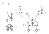
- FIG. 3 Schematic which shows the whole structure in one Embodiment of a manufacturing apparatus provided with a coating device.
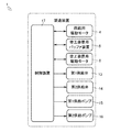
- the block diagram showing the control structure in one Embodiment of a manufacturing apparatus.
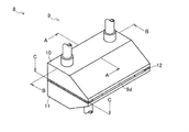
- the perspective view which shows 1st embodiment of the slit die in one Embodiment of a coating device.
- a manufacturing apparatus 1 that is an embodiment of a manufacturing apparatus including a coating apparatus will be described with reference to FIGS. 1 and 2.
- the manufacturing apparatus 1 is provided with only the coating apparatus 8 as a processing apparatus, but is not limited thereto.
- the manufacturing apparatus 1 manufactures a desired product by processing a belt-shaped web U (film substrate).
- the manufacturing apparatus 1 includes a web conveyance device 2, a coating device 8, and a control device 17.
- the web conveyance device 2 conveys the web U.
- the web conveyance device 2 includes a web storage unit 3, a supply drive motor 4, a coating device buffer device 5, a coating device drive motor 6, and a guide roller 7.
- the web storage unit 3 stores the web U to be supplied.
- the web storage unit 3 is arranged on the most upstream side in the web conveyance device 2.
- the web storage unit 3 is supported in a state in which the web roll Ua wound in a roll shape can rotate. That is, the web storage unit 3 is held in a state where the web U can be fed out from the web roll Ua by an arbitrary amount.
- the supply drive motor 4 that is an actuator that sends the web U supplies the web U from the web roll Ua to the downstream side.
- the supply drive motor 4 is disposed on the downstream side of the web storage unit 3.
- the drive motor 4 for supply is comprised from the servomotor which can control rotation speed and rotation speed.
- the supply drive motor 4 is provided with a supply drive roller 4a on the output shaft.
- the supply drive motor 4 is provided so that the supply drive roller 4 a contacts the web U.
- the supply drive motor 4 rotates the supply drive roller 4a based on a command value from the control device 17 and feeds the web U from the web roll Ua by an arbitrary amount.
- the coating device buffer device 5 adjusts the feed amount of the web U on the upstream side of the coating device buffer device 5 and the feed amount of the web U on the downstream side of the coating device buffer device 5. is there.
- the coating device buffer device 5 is arranged on the upstream side of the coating device 8.
- the coating device buffer device 5 adjusts the feed amount of the web U by changing the path length of the web U by the movement of the buffer roller. In other words, the coating device buffer device 5 absorbs the difference between the web U feed amount by the upstream supply drive motor 4 and the web U feed amount by the downstream coating device drive motor 6.
- the coating device drive motor 6 which is an actuator for feeding the web U, supplies the web U to the coating device 8.
- the coating device drive motor 6 is disposed on the downstream side of the coating device 8 provided in the web conveyance device 2.
- the coating apparatus drive motor 6 is composed of a servo motor capable of controlling the rotation speed and rotation speed.
- the coating apparatus drive motor 6 is provided with a coating apparatus drive roller 6a on the output shaft.
- the coating device drive motor 6 is provided so that the coating device drive roller 6 a contacts the web U.
- the coating device drive motor 6 rotates the coating device drive roller 6a based on a command value from the control device 17 to feed out the web U buffered in the coating device buffer device 5 by an arbitrary amount. , And supplied to the coating device 8.
- the guide roller 7 guides the web U to the coating device 8.
- the guide roller 7 is disposed so as to face the opening of the slit die 9 of the coating apparatus 8 described later.
- the guide roller 7 is configured to guide the web U by the outer peripheral surface.
- the guide roller 7 is supported rotatably.
- the web conveyance device 2 configured as described above feeds the web U from the web roll Ua of the web storage unit 3 by an arbitrary amount by the supply drive motor 4.
- the web conveyance device 2 sends the web U to the coating device 8 by the coating device drive motor 6.
- the web conveyance device 2 conveys the web U through the guide roller 7, whereby the coating liquid Lq is applied to the web U by the coating device 8. At this time, the web conveyance device 2 adjusts the feed amount of the web U to the coating device 8 by the coating device buffer device 5.
- the coating apparatus 8 which is one embodiment of the coating apparatus applies the coating liquid Lq to the web U.
- the coating device 8 is disposed on the downstream side of the coating device buffer device 5 constituting the web conveyance device 2 and on the upstream side of the coating device drive motor 6.
- the coating apparatus 8 includes a slit die 9 that discharges the coating liquid Lq, and a first supply valve 13 and a second supply valve 14 that constitute a coating liquid supply unit.
- a first supply pump 15 is connected to the first supply valve 13, and a second supply pump 16 is connected to the second supply valve 14.
- the slit die 9 of the coating device 8 is arranged so that the opening thereof faces the guide roller 7 that constitutes the web conveying device 2.
- the slit die 9 is arranged in such a manner that the coating liquid Lq can be discharged onto the surface of the web U that is continuously conveyed through the outer peripheral surface of the guide roller 7.
- the first supply valve 13 and the second supply valve 14 are connected to the slit die 9.
- the coating device 8 is configured to apply the coating liquid Lq to a predetermined region of the web U that passes through the guide roller 7 by opening and closing the first supply valve 13 and the second supply valve 14.
- the control device 17 controls the web conveyance device 2.
- the control device 17 may actually have a configuration in which a CPU, a ROM, a RAM, an HDD, and the like are connected by a bus, or may be configured by a one-chip LSI or the like.
- the control device 17 is connected to the control device 17 of the manufacturing apparatus 1 (not shown), and stores various programs and data for controlling the web conveyance device 2, the coating device 8, and the like.
- the control device 17 is connected to the supply drive motor 4 and the coating device drive motor 6, and transmits a command value for the feed amount of the web U to the supply drive motor 4 and the coating device drive motor 6, respectively.
- the web U can be controlled to be sent. Further, the control device 17 can acquire the operation amounts from the supply drive motor 4 and the coating device drive motor 6, respectively.
- the control device 17 is connected to the coating device buffer device 5 and controls the coating device buffer device 5 based on the feed amount of the web U by the supply drive motor 4 and the coating device drive motor 6. Can do.
- the control device 17 is connected to the first supply valve 13 and the second supply valve 14 of the coating device 8 and can control the opening and closing of the first supply valve 13 and the second supply valve 14.
- the control device 17 is connected to the supply pump 15 of the coating device 8 and can control the operation of the supply pump 15.
- the slit die 9 discharges the coating liquid Lq with a uniform coating thickness.
- the slit die 9 includes a one-side die member 10, an other-side die member 11, and a spacer 12 (light ink portion).
- the one side die member 10 and the other side die member 11 are main components of the slit die 9.
- the one-side die member 10 and the other-side die member 11 are formed in a substantially rectangular parallelepiped shape, and an inclined surface is formed so that the plate thickness on one long side becomes thin.
- the one-side die member 10 is formed with a joint surface 10a that can be brought into close contact with one side surface of the spacer 12 (light ink portion) in a watertight state.
- first concave portions 10b to which the coating liquid Lq is supplied are formed on both sides in the longitudinal direction.
- the other die member 11 is formed with a joint surface 11a that can be in close contact with the other side surface of the spacer 12 in a watertight state. Further, a second recess 11b to which the coating liquid Lq is supplied is formed at the center of the bonding surface 11a of the other die member 11.
- the spacer 12 constitutes a partition of the flow path.
- the spacer 12 is composed of a rectangular plate-like member having the same long side and short side as the joint surfaces 10 a and 11 a in the one-side die member 10 and the other-side die member 11.
- One side plane of the spacer 12 is formed in a plane that can be in close contact with the bonding surface 10a of the one-side die member 10 in a watertight state.
- the other side plane of the spacer 12 is formed as a plane that can be in close contact with the bonding surface 11 a of the other side die member 11 in a watertight state.
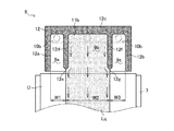
- the spacer 12 is formed with three notches cut from one long side to the other long side. That is, the spacer 12 is configured such that the short side portion on one side, the short side portion on the other side, and the long side portion on the other side are respectively formed as the one side short side frame 12a, the other side short side frame 12b, and the other side long side frame 12c. Has been. Further, the spacer 12 is formed with a comb-shaped first partition 12d and a second partition 12f extending from the other long side frame 12c to the long side on one side. The front end portion of the first partition 12d and the front end portion of the second partition 12f are formed in a triangular shape having an apex angle of 90 ° with the center in the width direction as a vertex.
- the one side end surface facing the notch portion and the other side end surface of the first partition 12d are configured to be close to each other and intersect at the front end 12e of the first partition 12d.
- the one end face and the other end face facing the notch portion in the second partition 12f are configured to be close to each other and intersect at the tip 12g of the second partition 12f.
- the front end 12e of the first partition 12d and the front end 12g of the second partition 12f are formed so as to be inside (the other long side) by a predetermined length L from one long side.
- one side plane of the spacer 12 is in watertight contact with the joint surface 10 a of the one side die member 10.
- the other side plane of the spacer 12 is in watertight contact with the bonding surface 11 a of the other side die member 11. That is, the one-side die member 10 and the other-side die member 11 are in watertight contact with the plane of the spacer 12 where the respective joint surfaces 10a and 11a face each other.
- the slit die 9 is formed by sandwiching the spacer 12 in which the cutout portion is formed between the one-side die member 10 and the other-side die member 11 and fixing them with a fastening member (not shown).
- a slit 9d (see FIG. 5) corresponding to the thickness of the spacer 12 is formed between the die 10 and the other die member 11.
- the slit die 9 is configured with a first side first flow path 9a using a notch portion on the one side short side frame 12a side among the three notch portions of the spacer 12 constituting the slit 9d,
- the other-side first flow path 9c is configured using the notch portion on the other-side short side frame 12b side, and the second flow path is utilized using the notch portion between the first partition 12d and the second partition 12f.
- 9b is configured.
- the slit die 9 includes a joining surface 10 a (see FIG. 5) of the one-side die member 10, a joining surface 11 a (see FIG. 5) of the other-side die member 11, and a spacer 12.
- the slit 9d portion surrounded by the one side short side frame 12a, the other side long side frame 12c of the spacer 12, and the first partition 12d of the spacer 12 is configured as the one side first flow path 9a.
- the slit die 9 includes a joining surface 10a (see FIG. 5) of the one-side die member 10, a joining surface 11a (see FIG. 5) of the other-side die member 11, the other-side short side frame 12b of the spacer 12, and the like.
- a slit 9d portion surrounded by the side long side frame 12c and the second partition 12f is configured as the other side first flow path 9c.
- the slit die 9 includes a joining surface 10a (see FIG. 5) of the one-side die member 10, a joining surface 11a (see FIG. 5) of the other-side die member 11, the other-side long side frame 12c of the spacer 12, A slit 9d portion surrounded by the first partition 12d and the second partition 12f is configured as a second flow path 9b.
- each 1st recessed part 10b of the one side die member 10 is a part which overlaps with the one side 1st flow path 9a among the joining surfaces 10a of the one side die member 10, and the other side 1st flow. It is formed in the part which overlaps with the path 9c.
- Each first recess 10b is formed to have a width substantially the same as the width of the first-side first flow path 9a and the other-side first flow path 9c.
- a first supply valve 13 is connected to each first recess 10b of the one-side die member 10 so that the coating liquid Lq can be supplied.
- the second recessed portion 11 b of the other side die member 11 is formed in a portion of the joint surface 11 a of the other side die member 11 that overlaps with the second flow path 9 b.
- the 2nd recessed part 11b is formed in the width
- a second supply valve 14 is connected to the second recess 11b of the other die member 11 so that the coating liquid Lq can be supplied. As shown in FIG. 5, in the slit die 9, the opening of the slit 9d is configured as a discharge port for the coating liquid Lq.
- the slit die 9 is configured such that the tip 12e of the first partition 12d and the tip 12g of the second partition 12f are recessed by a predetermined length L inside the opening of the slit 9d. That is, the slit die 9 has a slit 9d after the coating liquid Lq flows out from the outlets of the first-side first flow path 9a (see FIG. 4), the other-side first flow path 9c (see FIG. 4), and the second flow path 9b. Is passed through a predetermined length L and discharged from the opening of the slit 9d.
- the coating liquid Lq pressurized by the first supply pump 15 is in each first recess 10b.
- the coating liquid Lq supplied into the first recess 10b flows toward the outlet while spreading inside the one side first flow path 9a and the other side first flow path 9c by the pressure of the first supply pump 15 ( (Refer to the light ink and arrow).
- the coating liquid Lq flows along the one side short side frame 12a and the first partition 12d.
- the coating width of the coating liquid Lq flowing through the one-side first flow path 9a is such that the end face of the one-side first flow path 9a side of the one-side short side frame 12a of the spacer 12 at the outlet of the one-side first flow path 9a. It is determined by the distance W1 from the tip 12e of the first partition 12d.
- the coating width of the coating liquid Lq flowing through the other first flow path 9c is the same as the end face on the other first short flow path 9c side of the other short side frame 12b of the spacer 12 at the outlet of the other first flow path 9c. It is determined by a distance W3 from the tip 12e of the partition 12d.
- the coating liquid Lq is discharged from the opening of the slit die 9 through the outlets of the first first flow path 9a and the other first flow path 9c, and the first one on the web U being continuously conveyed. It is applied at a position facing the flow path 9a and the other first flow path 9c.
- the one-side first flow path 9a and the other-side first flow path 9c are applied to spaced positions on the web U because the second flow path 9b is formed therebetween.
- the coating apparatus 8 causes the coating liquid Lq pressurized by the second supply pump 16 to enter the second recess 11b. Filled.
- the coating liquid Lq filled in the second recess 11b flows toward the outlet while spreading inside the second flow path 9b by the pressure of the second supply pump 16 (see the thin ink portion and the arrow).
- the coating liquid Lq flows along the first partition 12d and the second partition 12f. That is, the coating width of the coating liquid Lq is determined by the interval W2 between the tip 12e of the first partition 12d of the spacer 12 and the tip 12g of the second partition 12f at the outlet of the second flow path 9b.
- the coating liquid Lq is discharged from the opening of the slit die 9 through the outlet of the second flow path 9b, and is applied to a position facing the second flow path 9b on the web U that is continuously conveyed.
- the coating device 8 is connected to the first supply pump 15 and the second supply.
- the coating liquid Lq spreads inside the one-side first flow path 9a, the other-side first flow path 9c, and the second flow path 9b by the pump 16, and the outlet of the one-side first flow path 9a, the other-side first flow path. It flows out from the outlet to 9c and the outlet of the second flow path 9b, respectively (refer to the thin ink portion and arrow).
- the coating liquid Lq that has flowed out of the first side first flow path 9a is a slit die at an interval W1 from the end surface on the first side first flow path 9a side of the one side short side frame 12a of the spacer 12 to the front end 12e of the first partition 12d. It flows toward 9 openings.
- the coating liquid Lq that has flowed out of the other first flow path 9c is a slit die at an interval W3 from the tip 12g of the second partition 12f to the end face of the other short side frame 12b of the spacer 12 on the one side first flow path 9a side. It flows toward 9 openings.
- the coating liquid Lq flowing out from the second flow path 9b flows toward the opening of the slit die 9 at a distance W2 from the tip 12e of the first partition 12d to the tip 12g of the second partition 12f.
- the position of the end on the second flow path 9b side of the coating liquid Lq flowing out from the first flow path 9a on the one side coincides with the position of the tip 12e of the first partition 12d.
- the position of the end of the coating liquid Lq that has flowed out of the second flow path 9b on the side of the first flow path 9a coincides with the position of the tip 12e of the first partition 12d. That is, the coating liquid Lq flowing out from the first first flow path 9a and the coating liquid Lq flowing out from the second flow path 9b merge at the tip 12e of the first partition 12d to form an integral coating liquid film. It becomes liquid Lq.
- the position of the end on the other first flow path 9c side of the coating liquid Lq that has flowed out of the second flow path 9b coincides with the position of the tip 12g of the second partition 12f. Further, the position of the end of the coating liquid Lq flowing out from the other first flow path 9c on the second flow path 9b side coincides with the position of the tip 12g of the second partition 12f. That is, the coating liquid Lq flowing out from the second flow path 9b and the coating liquid Lq flowing out from the other first flow path 9c merge at the tip 12g of the second partition 12f to form an integral coating liquid film. It becomes liquid Lq. As described above, in the coating apparatus 8, when the first supply valve 13 (see FIG. 4) and the second supply valve 14 (see FIG.
- the coating liquid Lq is one side short frame of the spacer 12.
- the outlet of each flow path as an integral coating film of the interval W1 + the interval W2 + the interval W3 from the end surface on the one side first flow channel 9a side of 12a to the end surface on the one side first flow channel 9a side on the other side short side frame 12b
- the coating liquid Lq that flows out from the first side first flow path 9a, the second flow path 9b, and the other side first flow path 9c is moderately moved while moving the slit 9d of the slit die 9 by a predetermined length L. They are mixed and discharged from the opening of the slit die 9 without a gap between the flow paths.
- the coating device 8 is configured to control the one-side first flow path 9 a and the other-side first through opening / closing control of the first supply valve 13 (see FIG. 4) and the second supply valve 14 (see FIG. 4).
- the coating liquid Lq can be supplied to the first flow path 9c and the second flow path 9b at an arbitrary timing, and the coating liquid Lq flowing out from each flow path can be applied onto the web U without any gap.
- the coating apparatus 8 opens the first supply valve 13 and the second supply valve 14 for a predetermined time, so that the one side short side frame 12a of the spacer 12 is opened.
- the coating liquid Lq is applied to the web U at the interval W1 + interval W2 + interval W3 from the end surface on the one side first flow channel 9a side to the end surface on the one side first flow channel 9a side on the other side short side frame 12b (light ink portion reference). Subsequently, the coating apparatus 8 keeps the first supply valve 13 in the open state, and closes the second supply valve 14 for a predetermined time, so that the first short side frame 12a on the one side of the spacer 12 is closed.
- the coating liquid Lq is applied to the web U (see the thin ink portion). Continuously, the coating apparatus 8 opens the first supply valve 13 and the second supply valve 14 for a predetermined time, so that one side of the short side frame 12a of the spacer 12 is on the side of the first flow path 9a.
- the coating liquid Lq is applied to the web U at the interval W1 + interval W2 + interval W3 from the end surface of the other side short side frame 12b to the end surface on the one-side first flow path 9a side (see the thin ink portion). By controlling in this way, the coating apparatus 8 can form a frame-shaped application region on the web U without a gap.
- the tip 12e of the first partition 12d of the spacer 12 and the tip 12g of the second partition 12f have a triangular shape with an apex angle of 90 °.
- Any structure may be used as long as the coating liquid Lq of the matching flow path is merged at the outlet of the flow path.
- the entire end surface on the one side first flow path 9a side and the entire end surface on the second flow path 9b side. May be formed on an inclined surface toward the approximate center of the first partition 12d.
- the end portion (or the whole) of the end surface on the one side first flow path 9a side is set to the second flow path 9b. You may form in the inclined surface which goes to the end surface of the side.
- the coating liquid Lq that flows through the width between adjacent flow paths is formed to a width that can be merged at the outlet. May be.
- the coating apparatus 8 configured as described above, a part of one of the coating liquids Lq discharged from the adjacent one side first flow path 9a, the other side first flow path 9c, and the second flow path 9b flows.
- the other coating liquid Lq is merged with the other coating liquid Lq at the exit of the path and is applied to the web U with a coating width corresponding to the width of the adjacent flow path.
- the coating apparatus 8 makes the coating thickness uniform by mixing the coating liquid Lq flowing out from the flow path by the slit 9d of the slit die 9.
- the application range of the coating liquid Lq is set according to the position and the number of the first partition 12d and the second partition 12f of the spacer 12. Thereby, the coating liquid Lq discharged from the adjacent one-side first flow path 9a, the other-side first flow path 9c, and the second flow path 9b does not overlap with each other, and no gap is generated. It can be applied to the area.
- the slit 9d of the slit die 9 is configured by the spacer 12.
- the present invention is not limited to this.
- a configuration in which a flow path is formed in the one-side die member 10 and the other-side die member 11 constituting the slit die 9 may be employed.
- two independent supply valves are connected to the slit die 9, and a flow path corresponding to the supply valve is configured.
- the present invention is not limited to this.
- the above-described embodiments are merely representative, and various modifications can be made without departing from the scope of one embodiment. It goes without saying that the present invention can be embodied in various forms, and the scope of the present invention is indicated by the description of the scope of claims, and the equivalent meanings of the scope of claims, and all the scopes within the scope of the claims. Includes changes.
Landscapes
- Coating Apparatus (AREA)
Abstract
隣り合う流路からそれぞれ吐出される塗液を重複することなく、かつ隙間が生じることなくウェブの所定の領域に塗布することができる塗工装置を提供する。具体的には、スリットダイ9を用いてウェブUに塗液を塗布する塗工装置8であってスリットダイ9のスリット9dの内部に、第1仕切り12dと第2仕切り12fとによって同一平面上の独立した複数の一側第1流路9a、他側第1流路9c、第2流路9bが構成され、独立して制御される第1供給弁13および第2供給弁14が、各流路に接続され、隣り合う一側第1流路9aと第2流路9bに塗液Lqが供給される場合、塗液Lqが一側第1流路9aと第2流路9bとの出口で合流し、スリットダイ9のスリット9dから吐出され、一側第1流路9aと他側第1流路9cとに塗液Lqが供給される場合、塗液Lqとが分離した状態でそれぞれスリットダイ9のスリット9dから吐出される。
Description
本発明は、塗工装置に関する。詳しくは、連続的に搬送されるウェブに塗液を所定の形状に塗布する塗工装置に関する。
従来、帯状のウェブに様々な材料の塗布や印刷等の加工を連続的に行う製造装置が知られている。ウェブに塗布や印刷等によって所定の加工を施し、加工後の複数のウェブを重ね合わせることで所望の機能を有する積層製品を連続的に製造するものである。このような製造装置において、ウェブに塗液を均一な塗布厚で所定の形状に塗布する塗工装置が設けられている。例えば特許文献1の如くである
特許文献1に記載の塗工装置は、複数のスリットが形成されている第1ダイ部材と第2ダイ部材とがスペーサーを介して一体的に締結されたダイ本体に複数の塗液供給手段が接続されている。ダイ本体には、第1ダイ部材のスリットとスペーサーの一側面とから複数の通液部が構成され、第2ダイ部材のスリットとスペーサーの他側面とから複数の通液部が構成されている。つまり、ダイ本体には、スペーサーを挟むようにして第1ダイ部材の通液部と第2ダイ部材の通液部とが構成されている。さらに、第1ダイ部材の通液部と第2ダイ部材の通液部とは、互いに重複しないように交互に配置されている。また、第一ダイ部材の通液部と第2ダイ部材の通液部とにそれぞれ塗液供給手段が接続されている。これにより、塗工装置は、それぞれの塗液供給手段を制御して所定の領域に塗液を塗布することができる。しかし、特許文献1に記載の技術は、第1ダイ部材の通液部を通じて塗布された塗工面と第2ダイ部材の通液部を通じて塗布された塗工面とがつながるように塗液を塗布する場合、通液部が隣接していないため塗工面が重複して塗工厚が厚くなったり、隙間が生じたりする可能性があった。
本発明の目的は、隣り合う流路からそれぞれ吐出される塗液を重複することなく、かつ隙間が生じることなくウェブの所定の領域に塗布することができる塗工装置の提供を目的とする。
本発明の解決しようとする課題は以上の如くであり、次にこの課題を解決するための手段を説明する。
即ち、塗工装置は、スリットダイを用いてウェブに塗液を塗布する塗工装置であって、前記スリットダイのスリット内部に、仕切りによって同一平面上の独立した複数の流路が構成され、独立して制御される複数の塗液供給手段が、前記複数の流路のうち対応する流路にそれぞれ接続され、前記複数の流路のうち、隣り合う一方の流路と他方の流路とに塗液が供給される場合、前記一方の流路を流れる塗液と他方の流路を流れる塗液とが前記一方の流路と他方の流路との出口で合流し、前記スリットダイのスリットから吐出され、前記複数の流路のうち、隣り合わない一方の流路と他方の流路とに塗液が供給される場合、前記一方の流路を流れる塗液と他方の流路を流れる塗液とが分離した状態でそれぞれ前記スリットダイのスリットから吐出されるものである。
塗工装置は、前記隣り合う一方の流路と他方の流路との間の仕切りにおいて、その出口側先端が前記スリットダイのスリットが開口している端面よりも内側かつ前記一方の流路を構成している側面と前記他方の流路を構成している側面とのうち少なくとも一方の側面が出口側先端部で他方の側面に近接するように形成されるものである。
塗工装置は、前記隣り合う一方の流路と他方の流路との間の仕切りにおいて、その出口側先端が前記スリットダイのスリットが開口している端面よりも内側かつ前記一方の流路を構成している側面と他方の流路を構成している側面とが前記出口側先端で交わるように形成されるものである。
塗工装置は、一方のダイと他方のダイとからなるダイ本体と、複数の仕切りが櫛歯状に形成され、前記一方のダイと前記他方のダイとの間に挟まれて配置される板状のスベーサーと、前記スリットダイと板状のスペーサーとから構成される複数の流路のうち、対応する流路にそれぞれ接続される複数の塗液供給バルブと、を備え、前記複数の仕切りの先端部が、前記スリットダイのスリットが開口している端面よりも内側かつ平面視で三角形状になるように形成され、前記複数の塗液供給バルブによって対応する流路に選択的に塗液が供給されるものである。
本発明の効果として、以下に示すような効果を奏する。
塗工装置においては、隣り合う流路からそれぞれ吐出された塗液が一体となって隣り合う流路の幅に応じた幅でウェブに塗布される。また、隣り合わない流路からそれぞれ吐出された塗液がそれぞれの流路の幅に応じた幅でウェブに塗布される。これにより、隣り合う流路からそれぞれ吐出される塗液を重複することなく、かつ隙間が生じることなくウェブの所定の領域に塗布することができる。
塗工装置においては、隣り合う流路からそれぞれ吐出された塗液のうち少なくとも一方の塗液の一部が流路の出口で他方の塗液と合流して一体となる。また、スリットダイによって塗液の塗布厚が均一にされる。これにより、隣り合う流路からそれぞれ吐出される塗液を重複することなく、かつ隙間が生じることなくウェブの所定の領域に塗布することができる。
塗工装置においては、スペーサーの形状によって塗液の塗布範囲が設定される。また、隣り合う流路からそれぞれ吐出された塗液が流路の出口で他方の塗液と合流して一体となる。さらに、スリットダイによって塗液の塗布厚が均一にされる。これにより、隣り合う流路からそれぞれ吐出される塗液を重複することなく、かつ隙間が生じることなくウェブの所定の領域に塗布することができる。
まず、図1と図2とを用いて、塗工装置を備える製造装置の一実施形態である製造装置1について説明する。なお、本実施形態において製造装置1には、加工装置として塗工装置8のみが設けられているがこれに限定されるものではない。
図1と図2とに示すように、製造装置1は、帯状のウェブU(フィルム基材)を加工して所望の製品を製造するものである。製造装置1は、ウェブ搬送装置2、塗工装置8、制御装置17、を具備している。
ウェブ搬送装置2は、ウェブUを搬送するものである。ウェブ搬送装置2は、ウェブ貯蔵部3、供給用駆動モータ4、塗工装置用バッファ装置5、塗工装置用駆動モータ6およびガイドローラ7、を備える。
ウェブ貯蔵部3は、供給するウェブUを貯蔵するものである。ウェブ貯蔵部3は、ウェブ搬送装置2における最も上流側に配置されている。ウェブ貯蔵部3は、ロール状に巻き取られているウェブロールUaが回転可能な状態で支持されている。つまり、ウェブ貯蔵部3は、ウェブロールUaからウェブUを任意の量だけ繰り出し可能な状態で保持されている。
ウェブUを送るアクチュエータである供給用駆動モータ4は、ウェブロールUaからウェブUを下流側に供給するものである。供給用駆動モータ4は、ウェブ貯蔵部3の下流側に配置されている。供給用駆動モータ4は、回転数や回転速度を制御可能なサーボモータから構成されている。供給用駆動モータ4は、出力軸に供給用駆動ローラ4aが設けられている。供給用駆動モータ4は、供給用駆動ローラ4aがウェブUに接触するように設けられている。供給用駆動モータ4は、制御装置17からの指令値に基づいて供給用駆動ローラ4aを回転させてウェブロールUaからウェブUを任意の量だけ繰り出す。
塗工装置用バッファ装置5は、塗工装置用バッファ装置5よりも上流側のウェブUの送り量と塗工装置用バッファ装置5よりも下流側のウェブUの送り量とを調整するものである。塗工装置用バッファ装置5は、塗工装置8の上流側に配置されている。塗工装置用バッファ装置5は、バッファローラーの移動によってウェブUの経路長さを変更してウェブUの送り量を調整する。すなわち、塗工装置用バッファ装置5は、上流側の供給用駆動モータ4によるウェブUの送り量と下流側の塗工装置用駆動モータ6によるウェブUの送り量との差を吸収する。
ウェブUを送るアクチュエータである塗工装置用駆動モータ6は、ウェブUを塗工装置8に供給するものである。塗工装置用駆動モータ6は、ウェブ搬送装置2に設けられている塗工装置8の下流側に配置されている。塗工装置用駆動モータ6は、回転数や回転速度を制御可能なサーボモータから構成されている。塗工装置用駆動モータ6は、出力軸に塗工装置用駆動ローラ6aが設けられている。塗工装置用駆動モータ6は、塗工装置用駆動ローラ6aがウェブUに接触するように設けられている。塗工装置用駆動モータ6は、制御装置17からの指令値に基づいて塗工装置用駆動ローラ6aを回転させて塗工装置用バッファ装置5にバッファされているウェブUを任意の量だけ繰り出し、塗工装置8に供給する。
ガイドローラ7は、ウェブUを塗工装置8に案内するものである。ガイドローラ7は、後述する塗工装置8のスリットダイ9の開口部と対向するように配置されている。ガイドローラ7は、外周面によってウェブUを案内するように構成されている。ガイドローラ7は、回転自在に支持されている。
このように構成されるウェブ搬送装置2は、供給用駆動モータ4によってウェブ貯蔵部3のウェブロールUaからウェブUを任意の量だけ繰り出す。ウェブ搬送装置2は、塗工装置用駆動モータ6によってウェブUを塗工装置8に送る。ウェブ搬送装置2は、ガイドローラ7を介してウェブUを搬送することで、塗工装置8によってウェブUに塗液Lqが塗布される。この際、ウェブ搬送装置2は、塗工装置8へのウェブUの送り量を塗工装置用バッファ装置5によって調整する。
塗工装置の一実施形態である塗工装置8は、ウェブUに塗液Lqを塗布するものである。塗工装置8は、ウェブ搬送装置2を構成する塗工装置用バッファ装置5の下流側であって塗工装置用駆動モータ6の上流側に配置されている。塗工装置8は、塗液Lqを吐出するスリットダイ9、塗液供給手段を構成している第1供給弁13および第2供給弁14を具備する。第1供給弁13には第1供給ポンプ15が接続され、第2供給弁14には第2供給ポンプ16が接続されている。塗工装置8のスリットダイ9は、その開口部がウェブ搬送装置2を構成するガイドローラ7と対向するように配置されている。つまり、スリットダイ9は、ガイドローラ7の外周面を通過して連続搬送されるウェブUの表面に塗液Lqを吐出可能な態様で配置されている。第1供給弁13および第2供給弁14は、スリットダイ9に接続されている。塗工装置8は、第1供給弁13および第2供給弁14の開閉によって、ガイドローラ7を通過するウェブUの所定の領域に塗液Lqを塗布するように構成されている。
図2に示すように、制御装置17は、ウェブ搬送装置2を制御するものである。制御装置17は、実体的には、CPU、ROM、RAM、HDD等がバスで接続される構成であってもよく、あるいはワンチップのLSI等からなる構成であってもよい。制御装置17は、図示しない製造装置1の制御装置17に接続され、ウェブ搬送装置2、塗工装置8等を制御するために種々のプログラムやデータが格納されている。
制御装置17は、供給用駆動モータ4と塗工装置用駆動モータ6とに接続され、供給用駆動モータ4と塗工装置用駆動モータ6とにそれぞれウェブUの送り量の指令値を送信してウェブUを送るように制御することができる。また、制御装置17は、供給用駆動モータ4と塗工装置用駆動モータ6とから作動量をそれぞれ取得することができる。
制御装置17は、塗工装置用バッファ装置5に接続され、供給用駆動モータ4と塗工装置用駆動モータ6とによるウェブUの送り量に基づいて塗工装置用バッファ装置5を制御することができる。
制御装置17は、塗工装置8の第1供給弁13および第2供給弁14に接続され、第1供給弁13および第2供給弁14の開閉を制御することができる。
制御装置17は、塗工装置8の供給ポンプ15に接続され、供給ポンプ15の動作を制御することができる。
以下では、図3から図6を用いて、塗工装置8のスリットダイ9の内部構造およびその機能について説明する。
図3に示すように、スリットダイ9は、塗液Lqを均一な塗布厚で吐出するものである。スリットダイ9は、一側ダイ部材10、他側ダイ部材11およびスペーサー12(薄墨部分)から構成されている。
一側ダイ部材10と他側ダイ部材11とは、スリットダイ9の主な構成部品である。一側ダイ部材10と他側ダイ部材11とは、略直方体状に形成され、一方の長辺側の板厚が薄くなるように傾斜面が形成されている。
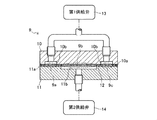
図4に示すように、一側ダイ部材10には、スペーサー12(薄墨部分)の一側面に水密状態で密着可能な接合面10aが形成されている。一側ダイ部材10の接合面10aには、長手方向の両側に塗液Lqが供給される第1凹部10bがそれぞれ形成されている。他側ダイ部材11には、スペーサー12の他側面に水密状態で密着可能な接合面11aが形成されている。さらに、他側ダイ部材11の接合面11aには、中央に塗液Lqが供給される第2凹部11bが形成されている。
図4に示すように、一側ダイ部材10には、スペーサー12(薄墨部分)の一側面に水密状態で密着可能な接合面10aが形成されている。一側ダイ部材10の接合面10aには、長手方向の両側に塗液Lqが供給される第1凹部10bがそれぞれ形成されている。他側ダイ部材11には、スペーサー12の他側面に水密状態で密着可能な接合面11aが形成されている。さらに、他側ダイ部材11の接合面11aには、中央に塗液Lqが供給される第2凹部11bが形成されている。
図6に示すように、スペーサー12は、流路の仕切りを構成しているものである。スペーサー12は、一側ダイ部材10と他側ダイ部材11とにおける接合面10a・11aと同一の長辺および短辺を有する長方形状の板状部材から構成されている。スペーサー12の一側平面は、一側ダイ部材10の接合面10aに水密状態で密着可能な平面に形成されている。スペーサー12の他側平面は、他側ダイ部材11の接合面11aに水密状態で密着可能な平面に形成されている。
スペーサー12は、一側の長辺から他側の長辺に向かって切り欠かれた3つの切欠き部分が形成されている。つまり、スペーサー12は、一側の短辺部分、他側の短辺部分および他側の長辺部分がそれぞれ一側短辺枠12a、他側短辺枠12bおよび他側長辺枠12cとして構成されている。さらに、スペーサー12は、他側長辺枠12cから一側の長辺側に延びる櫛歯状の第1仕切り12dと第2仕切り12fとが形成されている。第1仕切り12dの先端部と第2仕切り12fの先端部とは、その幅方向における中央を頂点とする頂角90°の三角形状に形成されている。つまり、第1仕切り12dにおいて切欠き部分に面している一側端面と他側端面とは、互いに近接して第1仕切り12dの先端12eで交わるように構成されている。同様にして、第2仕切り12fにおいて切欠き部分に面している一側端面と他側端面とは、互いに近接して第2仕切り12fの先端12gで交わるように構成されている。さらに、第1仕切り12dの先端12eと第2仕切り12fの先端12gとは、一方の長辺よりも所定長さLだけ内側(他方の長辺側)になるように形成されている。
図4と図5とに示すように、一側ダイ部材10の接合面10aには、スペーサー12の一側平面が水密的に密着されている。同様に、他側ダイ部材11の接合面11aには、スペーサー12の他側平面が水密的に密着されている。つまり、一側ダイ部材10と他側ダイ部材11とは、それぞれの接合面10a・11aが対向するスペーサー12の平面に水密的に密着されている。このようにして、スリットダイ9は、切欠き部分が形成されているスペーサー12を一側ダイ部材10と他側ダイ部材11とが挟み込み、図示しない締結部材で固定することで、一側ダイ部材10と他側ダイ部材11との間にスペーサー12の板厚分のスリット9d(図5参照)が構成されている。
スリットダイ9には、スリット9dを構成しているスペーサー12の3つの切欠き部分のうち、一側短辺枠12a側の切欠き部分を利用して一側第1流路9aが構成され、他側短辺枠12b側の切欠き部分を利用して他側第1流路9cが構成され、第1仕切り12dと第2仕切り12fとの間の切欠き部分を利用して第2流路9bが構成されている。
具体的には、図6に示すように、スリットダイ9には、一側ダイ部材10の接合面10a(図5参照)、他側ダイ部材11の接合面11a(図5参照)、スペーサー12の一側短辺枠12a、スペーサー12の他側長辺枠12cおよびスペーサー12の第1仕切り12dに囲まれているスリット9d部分が一側第1流路9aとして構成されている。同様に、スリットダイ9には、一側ダイ部材10の接合面10a(図5参照)、他側ダイ部材11の接合面11a(図5参照)、スペーサー12の他側短辺枠12b、他側長辺枠12cおよび第2仕切り12fに囲まれているスリット9d部分が他側第1流路9cとして構成されている。同様に、スリットダイ9には、一側ダイ部材10の接合面10a(図5参照)、他側ダイ部材11の接合面11a(図5参照)、スペーサー12の他側長辺枠12c、第1仕切り12dおよび第2仕切り12fに囲まれているスリット9d部分が第2流路9bとして構成されている。
図4に示すように、一側ダイ部材10の各第1凹部10bは、一側ダイ部材10の接合面10aのうち一側第1流路9aと重複している部分および他側第1流路9cと重複している部分に形成されている。各第1凹部10bは、一側第1流路9aおよび他側第1流路9cの幅と略同一の幅に形成されている。一側ダイ部材10の各第1凹部10bには、第1供給弁13が接続されて塗液Lqが供給可能に構成されている。他側ダイ部材11の第2凹部11bは、他側ダイ部材11の接合面11aのうち第2流路9bと重複している部分に形成されている。第2凹部11bは、第2流路9bの幅と略同一の幅に形成されている。他側ダイ部材11の第2凹部11bには、第2供給弁14が接続されて塗液Lqが供給可能に構成されている。
図5に示すように、スリットダイ9は、スリット9dの開口部が塗液Lqの吐出口として構成されている。一方、スリットダイ9は、第1仕切り12dの先端12eと第2仕切り12fの先端12gとがスリット9dの開口部よりも内側に所定長さLだけ凹むように構成されている。つまり、スリットダイ9は、塗液Lqが一側第1流路9a(図4参照)、他側第1流路9c(図4参照)および第2流路9bの出口から流出した後にスリット9dを所定長さLだけ通過してスリット9dの開口部から吐出されるように構成されている。
図5に示すように、スリットダイ9は、スリット9dの開口部が塗液Lqの吐出口として構成されている。一方、スリットダイ9は、第1仕切り12dの先端12eと第2仕切り12fの先端12gとがスリット9dの開口部よりも内側に所定長さLだけ凹むように構成されている。つまり、スリットダイ9は、塗液Lqが一側第1流路9a(図4参照)、他側第1流路9c(図4参照)および第2流路9bの出口から流出した後にスリット9dを所定長さLだけ通過してスリット9dの開口部から吐出されるように構成されている。
以下に図7から図10を用いて、塗工装置8による塗液Lqの塗布態様について具体的に説明する。
図7に示すように、塗工装置8は、第1供給弁13(図4参照)を開弁した場合、第1供給ポンプ15によって加圧されている塗液Lqが各第1凹部10b内に供給される。第1凹部10b内に供給された塗液Lqは、第1供給ポンプ15の圧力によって一側第1流路9aと他側第1流路9cとの内部に広がりながらその出口に向かって流れる(薄墨部分および矢印参照)。塗液Lqは、一側短辺枠12aと第1仕切り12dとに沿って流れる。つまり、一側第1流路9aを流れる塗液Lqの塗布幅は、一側第1流路9aの出口におけるスペーサー12の一側短辺枠12aの一側第1流路9a側の端面と第1仕切り12dの先端12eとの間隔W1によって定められる。他側第1流路9cを流れる塗液Lqの塗布幅は、他側第1流路9cの出口におけるスペーサー12の他側短辺枠12bの他側第1流路9c側の端面と第1仕切り12dの先端12eとの間隔W3によって定められる。塗液Lqは、一側第1流路9aと他側第1流路9cとの出口を経てスリットダイ9の開口部から吐出され、連続的に搬送されているウェブU上の一側第1流路9aおよび他側第1流路9cに対向する位置に塗布される。本実施形態において、一側第1流路9aと他側第1流路9cとは、その間に第2流路9bが構成されているため、ウェブU上の離間した位置に塗布される。
図8に示すように、塗工装置8は、第2供給弁14(図4参照)が開弁した場合、第2供給ポンプ16によって加圧されている塗液Lqが第2凹部11b内に充填される。第2凹部11b内に充填された塗液Lqは、第2供給ポンプ16の圧力によって第2流路9bの内部に広がりながらその出口に向かって流れる(薄墨部分および矢印参照)。塗液Lqは、第1仕切り12dと第2仕切り12fとに沿って流れる。つまり、塗液Lqの塗布幅は、第2流路9bの出口におけるスペーサー12の第1仕切り12dの先端12eと第2仕切り12fの先端12gとの間隔W2によって定められる。塗液Lqは、第2流路9bの出口を経てスリットダイ9の開口部から吐出され、連続的に搬送されているウェブU上の第2流路9bに対向する位置に塗布される。
図9に示すように、塗工装置8は、第1供給弁13(図4参照)と第2供給弁14(図4参照)とが開弁した場合、第1供給ポンプ15と第2供給ポンプ16とによって塗液Lqが一側第1流路9a、他側第1流路9cおよび第2流路9bの内部に広がり、一側第1流路9aの出口、他側第1流路9cとの出口および第2流路9bの出口からそれぞれ流出する(薄墨部分および矢印参照)。一側第1流路9aから流出した塗液Lqは、スペーサー12の一側短辺枠12aの一側第1流路9a側の端面から第1仕切り12dの先端12eまでの間隔W1でスリットダイ9の開口部に向かって流れる。他側第1流路9cから流出した塗液Lqは、第2仕切り12fの先端12gからスペーサー12の他側短辺枠12bの一側第1流路9a側の端面までの間隔W3でスリットダイ9の開口部に向かって流れる。第2流路9bから流出した塗液Lqは、第1仕切り12dの先端12eから第2仕切り12fの先端12gまでの間隔W2でスリットダイ9の開口部に向かって流れる。
この際、一側第1流路9aから流出した塗液Lqの第2流路9b側の端部の位置は、第1仕切り12dの先端12eの位置と一致する。また、第2流路9bから流出した塗液Lqの一側第1流路9a側の端部の位置は、第1仕切り12dの先端12eの位置と一致する。つまり、一側第1流路9aから流出した塗液Lqと第2流路9bから流出した塗液Lqとは、第1仕切り12dの先端12eで合流して一体の塗液膜を形成する塗液Lqになる。同様に、第2流路9bから流出した塗液Lqの他側第1流路9c側の端部の位置は、第2仕切り12fの先端12gの位置と一致する。また、他側第1流路9cから流出した塗液Lqの第2流路9b側の端部の位置は、第2仕切り12fの先端12gの位置と一致する。つまり、第2流路9bから流出した塗液Lqと他側第1流路9cから流出した塗液Lqとは、第2仕切り12fの先端12gで合流して一体の塗液膜を形成する塗液Lqになる。このように、塗工装置8は、第1供給弁13(図4参照)と第2供給弁14(図4参照)とが開弁した場合、塗液Lqがスペーサー12の一側短辺枠12aの一側第1流路9a側の端面から他側短辺枠12bの一側第1流路9a側の端面までの間隔W1+間隔W2+間隔W3の一体の塗液膜として各流路の出口からスリットダイ9の開口部に向かって流れる。一側第1流路9a、第2流路9bおよび他側第1流路9cから流出して合流した塗液Lqは、スリットダイ9のスリット9dを所定長さLだけ移動する間に適度に混じり合い、スリットダイ9の開口部から流路間の隙間なく吐出される。
図10に示すように、塗工装置8は、第1供給弁13(図4参照)と第2供給弁14(図4参照)との開閉制御によって一側第1流路9aと他側第1流路9c、および第2流路9bに任意のタイミングで塗液Lqを供給し、各流路から流出される塗液Lqを隙間なくウェブU上に塗布することができる。例えば、図10(a)に示すように、塗工装置8は、第1供給弁13と第2供給弁14とを所定時間だけ開状態にすることで、スペーサー12の一側短辺枠12aの一側第1流路9a側の端面から他側短辺枠12bの一側第1流路9a側の端面までの間隔W1+間隔W2+間隔W3で塗液LqをウェブUに塗布する(薄墨部分参照)。続けて、塗工装置8は、第1供給弁13の開状態を維持しつつ第2供給弁14を所定時間だけ閉状態にすることで、スペーサー12の一側短辺枠12aの一側第1流路9a側の端面から第1仕切り12dの先端12eまでの間隔W1および第2仕切り12fの先端12gから他側短辺枠12bの一側第1流路9a側の端面までの間隔W3で塗液LqをウェブUに塗布する(薄墨部分参照)。続けて、塗工装置8は、第1供給弁13と第2供給弁14とを所定時間だけ開状態にすることで、スペーサー12の一側短辺枠12aの一側第1流路9a側の端面から他側短辺枠12bの一側第1流路9a側の端面までの間隔W1+間隔W2+間隔W3で塗液LqをウェブUに塗布する(薄墨部分参照)。このように制御することで、塗工装置8は、ウェブU上に枠状の塗布領域を隙間なく形成することができる。
なお、本実施形態において、スペーサー12の第1仕切り12dの先端12eと第2仕切り12fの先端12gとは、頂角を90°とする三角形状としたがこれに限定されるものではなく、隣り合う流路の塗液Lqを流路の出口で合流させる構成であればよい。例えば、図11に示すスリットダイ9の第二実施形態のように、スペーサー12の第1仕切り12dにおいて、一側第1流路9a側の端面の全体と第2流路9b側の端面の全体とを第1仕切り12dの略中央に向かう傾斜面に形成してもよい。また、図12に示すスリットダイ9の第三実施形態のように、スペーサー12の第1仕切り12dにおいて、一側第1流路9a側の端面の先端部(または全体)を第2流路9b側の端面に向かう傾斜面に形成してもよい。また、図13に示すスリットダイ9の第四実施形態のように、スペーサー12の第1仕切り12dにおいて、隣り合う流路間の幅を流れる塗液Lqがその出口で合流可能な幅に形成してもよい。
このように構成される塗工装置8は、隣り合う一側第1流路9a、他側第1流路9cおよび第2流路9bからそれぞれ吐出された一方の塗液Lqの一部が流路の出口で他方の塗液Lqと合流して一体となって隣り合う流路の幅に応じた塗布幅でウェブUに塗布される。さらに、塗工装置8は、スリットダイ9のスリット9dよって流路から流出した塗液Lqが混ざりあうことで塗布厚が均一にされる。また、塗工装置8は、スペーサー12の第1仕切り12dと第2仕切り12fとの位置やその数によって塗液Lqの塗布範囲が設定される。これにより、隣り合う一側第1流路9a、他側第1流路9cおよび第2流路9bからそれぞれ吐出される塗液Lqを重複することなく、かつ隙間が生じることなくウェブUの所定の領域に塗布することができる。
以上、塗工装置の一実施形態である塗工装置8は、スリットダイ9のスリット9dがスペーサー12によって構成されているものとしたがこれに限定されるものではない。すべての実施形態において、スリットダイ9を構成している一側ダイ部材10と他側ダイ部材11とに流路を形成する構成でもよい。また、スリットダイ9には、二つの独立した供給弁が接続され、供給弁に対応した流路が構成されているがこれに限定されるものではない。上述の実施形態は、代表的な形態を示したに過ぎず、一実施形態の骨子を逸脱しない範囲で種々変形して実施することができる。さらに種々なる形態で実施し得ることは勿論のことであり、本発明の範囲は、特許請求の範囲の記載によって示され、さらに特許請求の範囲に記載の均等の意味、および範囲内のすべての変更を含む。
8 塗工装置
9 スリットダイ
9d スリット
9a 一側第1流路
9c 他側第1流路
9b 第2流路
13 第1供給弁
14 第2供給弁
U ウェブ
Lq 塗液
9 スリットダイ
9d スリット
9a 一側第1流路
9c 他側第1流路
9b 第2流路
13 第1供給弁
14 第2供給弁
U ウェブ
Lq 塗液
Claims (4)
- スリットダイを用いてウェブに塗液を塗布する塗工装置であって、
前記スリットダイのスリット内部に、仕切りによって同一平面上の独立した複数の流路が構成され、
独立して制御される複数の塗液供給手段が、前記複数の流路のうち対応する流路にそれぞれ接続され、
前記複数の流路のうち、隣り合う一方の流路と他方の流路とに塗液が供給される場合、
前記一方の流路を流れる塗液と他方の流路を流れる塗液とが前記一方の流路と他方の流路との出口で合流し、前記スリットダイのスリットから吐出され、
前記複数の流路のうち、隣り合わない一方の流路と他方の流路とに塗液が供給される場合、前記一方の流路を流れる塗液と他方の流路を流れる塗液とが分離した状態でそれぞれ前記スリットダイのスリットから吐出される塗工装置。 - 前記隣り合う一方の流路と他方の流路との間の仕切りにおいて、その出口側先端が前記スリットダイのスリットが開口している端面よりも内側かつ前記一方の流路を構成している側面と前記他方の流路を構成している側面とのうち少なくとも一方の側面が出口側先端部で他方の側面に近接するように形成される請求項1に記載の塗工装置。
- 前記隣り合う一方の流路と他方の流路との間の仕切りにおいて、その出口側先端が前記スリットダイのスリットが開口している端面よりも内側かつ前記一方の流路を構成している側面と他方の流路を構成している側面とが前記出口側先端で交わるように形成される請求項1または請求項2に記載の塗工装置。
- 一方のダイと他方のダイとからなるダイ本体と、
複数の仕切りが櫛歯状に形成され、前記一方のダイと前記他方のダイとの間に挟まれて配置される板状のスベーサーと、
前記スリットダイと板状のスペーサーとから構成される複数の流路のうち、対応する流路にそれぞれ接続される複数の塗液供給バルブと、を備え、
前記複数の仕切りの先端部が、前記スリットダイのスリットが開口している端面よりも内側かつ平面視で三角形状になるように形成され、前記複数の塗液供給バルブによって対応する流路に選択的に塗液が供給される塗工装置。
Applications Claiming Priority (2)
| Application Number | Priority Date | Filing Date | Title |
|---|---|---|---|
| JP2016-019356 | 2016-02-03 | ||
| JP2016019356A JP2017136551A (ja) | 2016-02-03 | 2016-02-03 | 塗工装置 |
Publications (1)
| Publication Number | Publication Date |
|---|---|
| WO2017135023A1 true WO2017135023A1 (ja) | 2017-08-10 |
Family
ID=59500637
Family Applications (1)
| Application Number | Title | Priority Date | Filing Date |
|---|---|---|---|
| PCT/JP2017/001294 Ceased WO2017135023A1 (ja) | 2016-02-03 | 2017-01-17 | 塗工装置 |
Country Status (2)
| Country | Link |
|---|---|
| JP (1) | JP2017136551A (ja) |
| WO (1) | WO2017135023A1 (ja) |
Families Citing this family (9)
| Publication number | Priority date | Publication date | Assignee | Title |
|---|---|---|---|---|
| JP6917329B2 (ja) * | 2018-03-22 | 2021-08-11 | 東レエンジニアリング株式会社 | 塗布装置 |
| JP6891850B2 (ja) * | 2018-04-25 | 2021-06-18 | トヨタ自動車株式会社 | ダイ塗工装置 |
| JP7155881B2 (ja) | 2018-10-31 | 2022-10-19 | トヨタ自動車株式会社 | 電極板、これを用いた電池、電極板の製造方法、これを用いた電池の製造方法、ダイヘッド |
| CN111282768B (zh) * | 2018-12-07 | 2021-09-07 | 财团法人工业技术研究院 | 夹片与狭缝式涂布器 |
| TWM577762U (zh) * | 2018-12-07 | 2019-05-11 | 財團法人工業技術研究院 | Clip and slot coater applying the same |
| JP7163334B2 (ja) * | 2020-03-13 | 2022-10-31 | 東レエンジニアリング株式会社 | スリットダイ |
| JP2023025608A (ja) * | 2021-08-10 | 2023-02-22 | 株式会社ラボ | 混成防止塗工装置 |
| EP4279184A1 (en) | 2022-05-19 | 2023-11-22 | LG Energy Solution, Ltd. | System for deposition of material |
| KR20250031879A (ko) * | 2023-08-29 | 2025-03-07 | 주식회사 엘지에너지솔루션 | 분할 매니폴드를 구비한 슬롯 다이 |
Citations (6)
| Publication number | Priority date | Publication date | Assignee | Title |
|---|---|---|---|---|
| US5773080A (en) * | 1997-04-17 | 1998-06-30 | Simmons; George | Pattern coating of thick film pressure sensitive adhesives |
| JP2001006664A (ja) * | 1999-06-22 | 2001-01-12 | Matsushita Electric Ind Co Ltd | 塗布装置 |
| JP2004098012A (ja) * | 2002-09-12 | 2004-04-02 | Seiko Epson Corp | 薄膜形成方法、薄膜形成装置、光学素子、有機エレクトロルミネッセンス素子、半導体素子および電子機器 |
| JP2005199129A (ja) * | 2004-01-13 | 2005-07-28 | Seiko Epson Corp | 塗布装置 |
| JP2014022149A (ja) * | 2012-07-17 | 2014-02-03 | Dainippon Screen Mfg Co Ltd | 電池用電極製造装置、電池用電極製造のためのノズルおよび電池用電極の製造方法 |
| JP2014172031A (ja) * | 2013-03-13 | 2014-09-22 | Toray Eng Co Ltd | 塗布器、パターン塗布装置およびパターン塗布方法 |
-
2016
- 2016-02-03 JP JP2016019356A patent/JP2017136551A/ja active Pending
-
2017
- 2017-01-17 WO PCT/JP2017/001294 patent/WO2017135023A1/ja not_active Ceased
Patent Citations (6)
| Publication number | Priority date | Publication date | Assignee | Title |
|---|---|---|---|---|
| US5773080A (en) * | 1997-04-17 | 1998-06-30 | Simmons; George | Pattern coating of thick film pressure sensitive adhesives |
| JP2001006664A (ja) * | 1999-06-22 | 2001-01-12 | Matsushita Electric Ind Co Ltd | 塗布装置 |
| JP2004098012A (ja) * | 2002-09-12 | 2004-04-02 | Seiko Epson Corp | 薄膜形成方法、薄膜形成装置、光学素子、有機エレクトロルミネッセンス素子、半導体素子および電子機器 |
| JP2005199129A (ja) * | 2004-01-13 | 2005-07-28 | Seiko Epson Corp | 塗布装置 |
| JP2014022149A (ja) * | 2012-07-17 | 2014-02-03 | Dainippon Screen Mfg Co Ltd | 電池用電極製造装置、電池用電極製造のためのノズルおよび電池用電極の製造方法 |
| JP2014172031A (ja) * | 2013-03-13 | 2014-09-22 | Toray Eng Co Ltd | 塗布器、パターン塗布装置およびパターン塗布方法 |
Also Published As
| Publication number | Publication date |
|---|---|
| JP2017136551A (ja) | 2017-08-10 |
Similar Documents
| Publication | Publication Date | Title |
|---|---|---|
| WO2017135023A1 (ja) | 塗工装置 | |
| US10213805B2 (en) | Wide pattern nozzle | |
| EP1880773B1 (en) | Spreading head particularly for spreading one or more adhesives or mixtures of adhesives | |
| US20110014430A1 (en) | Metering system for hot melt adhesives with variable adhesive volumes | |
| US20050241575A1 (en) | Extrusion applicator having linear motion operability | |
| EP1880772B1 (en) | Spreading head particularly for spreading one or more adhesives or mixtures of adhesives | |
| US20110030613A1 (en) | Curtain coater | |
| RU2343238C1 (ru) | Устройство для нанесения текучих сред на товарное полотно | |
| US9044764B2 (en) | Device for applying viscous media | |
| EP2949448B1 (en) | Multi-manifold extrusion die with deckle system and method of using same | |
| KR20190019054A (ko) | 도포기 및 도포 장치 | |
| JP4409961B2 (ja) | 帯状塗布用のダイリップ | |
| JP2011092934A (ja) | 基板を案内する装置及び流体を分配する装置 | |
| US10744524B2 (en) | Variable volume strand coating apparatus and method | |
| JP2009202141A (ja) | スリットダイ及びスリットダイコータ | |
| EP2550140B1 (en) | Sheet forming apparatus for use with doctor blade | |
| BR102012027524A2 (pt) | Máquina revestidora de cortina | |
| FI108242B (fi) | Lyhytratainen päällystyslaite | |
| JP2011194291A (ja) | コーティングダイ | |
| WO2026074771A1 (ja) | 塗布装置 | |
| WO2024111449A1 (ja) | スロット型スプレーノズル | |
| KR101424598B1 (ko) | 액체 이송 장치 | |
| JP2017137168A (ja) | ウェブ搬送装置 | |
| JP2011521855A (ja) | 平坦な箔材片からスリーブ状の箔被覆を形成するデバイス | |
| JP2004283654A (ja) | ゾル状物質塗布方法及びゾル状物質塗布装置 |
Legal Events
| Date | Code | Title | Description |
|---|---|---|---|
| 121 | Ep: the epo has been informed by wipo that ep was designated in this application |
Ref document number: 17747185 Country of ref document: EP Kind code of ref document: A1 |
|
| NENP | Non-entry into the national phase |
Ref country code: DE |
|
| 122 | Ep: pct application non-entry in european phase |
Ref document number: 17747185 Country of ref document: EP Kind code of ref document: A1 |