WO2017130874A1 - リアクトル - Google Patents
リアクトル Download PDFInfo
- Publication number
- WO2017130874A1 WO2017130874A1 PCT/JP2017/002034 JP2017002034W WO2017130874A1 WO 2017130874 A1 WO2017130874 A1 WO 2017130874A1 JP 2017002034 W JP2017002034 W JP 2017002034W WO 2017130874 A1 WO2017130874 A1 WO 2017130874A1
- Authority
- WO
- WIPO (PCT)
- Prior art keywords
- wiring
- reactor
- locking member
- stay
- winding
- Prior art date
- Legal status (The legal status is an assumption and is not a legal conclusion. Google has not performed a legal analysis and makes no representation as to the accuracy of the status listed.)
- Ceased
Links
Images


Classifications
-
- H—ELECTRICITY
- H01—ELECTRIC ELEMENTS
- H01F—MAGNETS; INDUCTANCES; TRANSFORMERS; SELECTION OF MATERIALS FOR THEIR MAGNETIC PROPERTIES
- H01F27/00—Details of transformers or inductances, in general
- H01F27/28—Coils; Windings; Conductive connections
- H01F27/30—Fastening or clamping coils, windings, or parts thereof together; Fastening or mounting coils or windings on core, casing, or other support
-
- H—ELECTRICITY
- H01—ELECTRIC ELEMENTS
- H01F—MAGNETS; INDUCTANCES; TRANSFORMERS; SELECTION OF MATERIALS FOR THEIR MAGNETIC PROPERTIES
- H01F27/00—Details of transformers or inductances, in general
- H01F27/02—Casings
-
- H—ELECTRICITY
- H01—ELECTRIC ELEMENTS
- H01F—MAGNETS; INDUCTANCES; TRANSFORMERS; SELECTION OF MATERIALS FOR THEIR MAGNETIC PROPERTIES
- H01F27/00—Details of transformers or inductances, in general
- H01F27/24—Magnetic cores
-
- H—ELECTRICITY
- H01—ELECTRIC ELEMENTS
- H01F—MAGNETS; INDUCTANCES; TRANSFORMERS; SELECTION OF MATERIALS FOR THEIR MAGNETIC PROPERTIES
- H01F27/00—Details of transformers or inductances, in general
- H01F27/40—Structural association with built-in electric component, e.g. fuse
- H01F27/402—Association of measuring or protective means
-
- H—ELECTRICITY
- H01—ELECTRIC ELEMENTS
- H01F—MAGNETS; INDUCTANCES; TRANSFORMERS; SELECTION OF MATERIALS FOR THEIR MAGNETIC PROPERTIES
- H01F37/00—Fixed inductances not covered by group H01F17/00
-
- H—ELECTRICITY
- H01—ELECTRIC ELEMENTS
- H01F—MAGNETS; INDUCTANCES; TRANSFORMERS; SELECTION OF MATERIALS FOR THEIR MAGNETIC PROPERTIES
- H01F27/00—Details of transformers or inductances, in general
- H01F27/40—Structural association with built-in electric component, e.g. fuse
- H01F27/402—Association of measuring or protective means
- H01F2027/406—Temperature sensor or protection
Definitions
- the present invention relates to a reactor.
- This application claims priority based on Japanese Patent Application No. 2016-013754 filed on Jan. 27, 2016, and incorporates all the contents described in the above Japanese application.
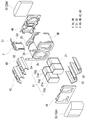
- the coil 2 in the present embodiment includes a pair of winding portions 2A and 2B and a connecting portion 2R that connects both the winding portions 2A and 2B. Both end portions 2a and 2b of the coil 2 are extended from the winding portions 2A and 2B and connected to a terminal member (not shown). An external device such as a power source for supplying power is connected to the coil 2 through the terminal member.
- the winding portions 2A and 2B provided in the coil 2 are formed in a hollow cylindrical shape with the same number of turns and the same winding direction, and are arranged in parallel so that the axial directions are parallel to each other.
- the connecting portion 2R is a portion bent in a U shape that connects the two winding portions 2A and 2B.
- Each winding part 2A, 2B of this embodiment is formed in a rectangular tube shape.
- the rectangular tube-shaped winding parts 2A and 2B are winding parts whose end face shape is a square shape (including a square shape) with rounded corners.
- the winding portions 2A and 2B may be formed in a cylindrical shape.
- the cylindrical winding portion is a winding portion whose end face shape is a closed curved surface shape (an elliptical shape, a perfect circle shape, a race track shape, etc.).
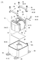
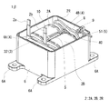
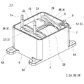
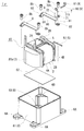
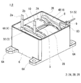
- the case (base body) 6 is a bottomed box-shaped member composed of a bottom plate portion (mounting plate) 60 and a side wall portion 61, and the assembly 10 is accommodated therein. To do.
- the case 6 of this example there are four fixing portions 6A (only three can be seen on the paper surface) that protrude outward from the case 6, and four pedestal portions 6B (on the paper surface) formed inside the case 6. Only one is visible).
- the fixing portion 6A is a member for fixing the case 6 to an installation target such as a cooling base, and in this example, a hole for screwing is formed.
- the binding band 9 includes a string-like body 90 made of resin or the like, and a fastening portion 91 formed at one end of the string-like body 90.
- the other end of the string-like body 90 is inserted into the through-hole 6Ch of the wiring locking member 6C, the string-like body 90 is wound around the outer periphery of the wiring portion 51, and the other end is then inserted into the hole of the fastening portion 91.
- the wiring portion 51 is bound to the wiring locking member 6C by the string-like body 90 by being inserted and pulled.
- the end surface interposing member 4B of the present example has a wiring locking member at the upper end position and at the width direction end portion (end portion on the winding portion 2B side in FIGS. 4 and 5).
- the wiring locking member 40 includes a root portion extending in a direction away from the winding portion 2B in the axial direction of the winding portion 2B (FIGS. 4 and 5), and an upper portion of the combined body 10 (FIGS. 4 and 5) from the tip of the root portion. And a pedestal portion extending to the side.
- a through hole 40 h is formed in a portion of the wiring locking member 40 that extends above the combined body 10. Similar to the first embodiment, the through-hole 40h is provided for inserting the string-like body 90 of the binding band 9 when the wiring portion 51 is fixed to the wiring locking member 40.
- the end surface interposed member 4 ⁇ / b> B of this example includes a guide portion 41 that guides the wiring portion 51 (FIGS. 4 and 5) to the wiring locking member 40 in addition to the wiring locking member 40.
- the guide part 41 is formed in a hook shape protruding in the direction away from the winding part 2B in the axial direction of the winding part 2B (FIGS. 4 and 5). By placing the wiring portion 51 (FIGS. 4 and 5) along the lower surface of the guide portion 41, the wiring portion 51 can be guided to the wiring locking member 40.
- the wiring locking member 40 and the guide portion 41 can be integrally formed with the end surface interposed member 4B by resin molding.
- the other end of the string-like body 90 is inserted into the through hole 40h of the wiring locking member 40 and the string-like body 90 is wound around the outer periphery of the wiring portion 51, the other end is fastened.
- the wiring portion 51 can be bound to the wiring locking member 40 by the string 90 by being inserted into the hole 91 and pulled.
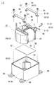
- the locking piece 7 is a substantially L-shaped member including a leg piece 71 and a base piece 72 as shown in FIG.
- the leg piece 71 is formed with a screw hole 71h through which a screw 8b for fixing the stay 8 passes.
- the pedestal piece 72 is formed with a through hole 72 h that is used for fixing the wiring portion 51 by the binding band 9.
- the pedestal piece 72 has such a length that the through-hole 72 h is disposed above the opening of the case 6. By doing so, it becomes easy to attach the binding band 9 to the through hole 72h.
- the wiring part 51 can be bound to the locking piece 7 by the string-like body 90 by inserting and pulling the other end into the hole of the fastening part 91. Since the locking piece 7 is screwed to the case 6, the wiring part 51 bound to the locking piece 7 is securely fixed to the case 6.
- the stay 8 of this example includes an upper piece 80 and a pair of leg pieces 81, 81, and a wiring locking member 83 that extends from the end of one leg piece 81 to the upper side of the combined body 10.
- a through hole 83 h is formed on the end side of the wiring locking member 83.
- the other end of the string-like body 90 is inserted into the through hole 83h of the wiring locking member 83 and the string-like body 90 is wound around the outer periphery of the wiring portion 51, the other end is fastened.
- the wiring portion 51 can be bound to the wiring locking member 83 by the string 90 by being inserted into the hole 91 and pulled.
- a reactor without the case 6 can be provided.
- a wiring fixing structure using a binding band can be applied to a reactor in which the assembly is disposed on a mounting plate.
- a stay with a long leg piece may be used and the leg piece of the stay may be screwed to the mounting plate.
- the reactor according to the embodiment of the present invention can be used for a power conversion device such as a bidirectional DC-DC converter mounted on an electric vehicle such as a hybrid vehicle, an electric vehicle, and a fuel cell vehicle.
- a power conversion device such as a bidirectional DC-DC converter mounted on an electric vehicle such as a hybrid vehicle, an electric vehicle, and a fuel cell vehicle.
Landscapes
- Engineering & Computer Science (AREA)
- Power Engineering (AREA)
- Dc-Dc Converters (AREA)
- Regulation Of General Use Transformers (AREA)
- Housings And Mounting Of Transformers (AREA)
- Inverter Devices (AREA)
Priority Applications (2)
| Application Number | Priority Date | Filing Date | Title |
|---|---|---|---|
| US16/069,629 US11158452B2 (en) | 2016-01-27 | 2017-01-20 | Reactor |
| CN201780006255.0A CN108780695B (zh) | 2016-01-27 | 2017-01-20 | 电抗器 |
Applications Claiming Priority (2)
| Application Number | Priority Date | Filing Date | Title |
|---|---|---|---|
| JP2016013754A JP6573075B2 (ja) | 2016-01-27 | 2016-01-27 | リアクトル |
| JP2016-013754 | 2016-01-27 |
Publications (1)
| Publication Number | Publication Date |
|---|---|
| WO2017130874A1 true WO2017130874A1 (ja) | 2017-08-03 |
Family
ID=59397853
Family Applications (1)
| Application Number | Title | Priority Date | Filing Date |
|---|---|---|---|
| PCT/JP2017/002034 Ceased WO2017130874A1 (ja) | 2016-01-27 | 2017-01-20 | リアクトル |
Country Status (4)
| Country | Link |
|---|---|
| US (1) | US11158452B2 (enExample) |
| JP (1) | JP6573075B2 (enExample) |
| CN (1) | CN108780695B (enExample) |
| WO (1) | WO2017130874A1 (enExample) |
Cited By (4)
| Publication number | Priority date | Publication date | Assignee | Title |
|---|---|---|---|---|
| DE102019100517A1 (de) * | 2019-01-10 | 2020-07-16 | EWS GmbH | Spulenkörperschale und Spulenkörper |
| DE202021105084U1 (de) | 2021-09-21 | 2021-09-29 | EWS GmbH | Spule |
| EP4152352A1 (de) | 2021-09-21 | 2023-03-22 | EWS GmbH | Spule |
| DE102021124334A1 (de) | 2021-09-21 | 2023-03-23 | EWS GmbH european winding systems | Spule |
Families Citing this family (3)
| Publication number | Priority date | Publication date | Assignee | Title |
|---|---|---|---|---|
| JP7133311B2 (ja) * | 2017-12-28 | 2022-09-08 | 株式会社タムラ製作所 | リアクトル |
| JP7205807B2 (ja) * | 2018-11-15 | 2023-01-17 | 株式会社オートネットワーク技術研究所 | リアクトル |
| JP6679061B1 (ja) * | 2020-02-07 | 2020-04-15 | 株式会社エス・エッチ・ティ | カレントトランスモジュール |
Citations (5)
| Publication number | Priority date | Publication date | Assignee | Title |
|---|---|---|---|---|
| JPS5090144U (enExample) * | 1973-12-18 | 1975-07-30 | ||
| JPS5240336Y2 (enExample) * | 1973-06-11 | 1977-09-12 | ||
| JP2012084674A (ja) * | 2010-10-10 | 2012-04-26 | Nippon Lock:Kk | サーミスタ温度センサー |
| WO2012114890A1 (ja) * | 2011-02-25 | 2012-08-30 | 住友電気工業株式会社 | リアクトル |
| JP2013222813A (ja) * | 2012-04-16 | 2013-10-28 | Sumitomo Electric Ind Ltd | リアクトル、コンバータ、および電力変換装置 |
Family Cites Families (11)
| Publication number | Priority date | Publication date | Assignee | Title |
|---|---|---|---|---|
| JP4535300B2 (ja) * | 2008-08-22 | 2010-09-01 | 住友電気工業株式会社 | リアクトル用部品およびリアクトル |
| JP5143043B2 (ja) | 2009-02-10 | 2013-02-13 | 株式会社タムラ製作所 | リード線を有する測定体の固定構造 |
| JP4834201B2 (ja) * | 2009-03-05 | 2011-12-14 | 株式会社タムラ製作所 | リードを有するセンサ素子の固定構造 |
| JP5120678B2 (ja) * | 2011-05-10 | 2013-01-16 | 住友電気工業株式会社 | リアクトル |
| JP5120679B1 (ja) * | 2011-05-10 | 2013-01-16 | 住友電気工業株式会社 | リアクトル |
| CN102290213A (zh) * | 2011-05-13 | 2011-12-21 | 张家港新特变科技有限公司 | 电炉变压器中绕组上抽头的固定方法 |
| CN102767871B (zh) * | 2012-06-13 | 2016-12-21 | Tcl空调器(中山)有限公司 | 电控盒的扎带及其扎线结构 |
| JP5881015B2 (ja) * | 2012-12-28 | 2016-03-09 | 株式会社オートネットワーク技術研究所 | リアクトル、コンバータ、および電力変換装置 |
| US9343223B2 (en) * | 2013-03-29 | 2016-05-17 | Tamura Corporation | Reactor |
| CN203397857U (zh) * | 2013-06-17 | 2014-01-15 | 上海正罡电气有限公司 | 采用捆扎固定接线端的线圈 |
| JP6327501B2 (ja) * | 2013-09-30 | 2018-05-23 | 日立金属株式会社 | リアクトル |
-
2016
- 2016-01-27 JP JP2016013754A patent/JP6573075B2/ja active Active
-
2017
- 2017-01-20 CN CN201780006255.0A patent/CN108780695B/zh active Active
- 2017-01-20 US US16/069,629 patent/US11158452B2/en active Active
- 2017-01-20 WO PCT/JP2017/002034 patent/WO2017130874A1/ja not_active Ceased
Patent Citations (5)
| Publication number | Priority date | Publication date | Assignee | Title |
|---|---|---|---|---|
| JPS5240336Y2 (enExample) * | 1973-06-11 | 1977-09-12 | ||
| JPS5090144U (enExample) * | 1973-12-18 | 1975-07-30 | ||
| JP2012084674A (ja) * | 2010-10-10 | 2012-04-26 | Nippon Lock:Kk | サーミスタ温度センサー |
| WO2012114890A1 (ja) * | 2011-02-25 | 2012-08-30 | 住友電気工業株式会社 | リアクトル |
| JP2013222813A (ja) * | 2012-04-16 | 2013-10-28 | Sumitomo Electric Ind Ltd | リアクトル、コンバータ、および電力変換装置 |
Cited By (4)
| Publication number | Priority date | Publication date | Assignee | Title |
|---|---|---|---|---|
| DE102019100517A1 (de) * | 2019-01-10 | 2020-07-16 | EWS GmbH | Spulenkörperschale und Spulenkörper |
| DE202021105084U1 (de) | 2021-09-21 | 2021-09-29 | EWS GmbH | Spule |
| EP4152352A1 (de) | 2021-09-21 | 2023-03-22 | EWS GmbH | Spule |
| DE102021124334A1 (de) | 2021-09-21 | 2023-03-23 | EWS GmbH european winding systems | Spule |
Also Published As
| Publication number | Publication date |
|---|---|
| US20190013144A1 (en) | 2019-01-10 |
| US11158452B2 (en) | 2021-10-26 |
| JP6573075B2 (ja) | 2019-09-11 |
| CN108780695A (zh) | 2018-11-09 |
| CN108780695B (zh) | 2020-09-18 |
| JP2017135258A (ja) | 2017-08-03 |
Similar Documents
| Publication | Publication Date | Title |
|---|---|---|
| JP6573075B2 (ja) | リアクトル | |
| CN107004497B (zh) | 电抗器 | |
| JP5120678B2 (ja) | リアクトル | |
| JP6365941B2 (ja) | リアクトル | |
| US20190131052A1 (en) | Reactor | |
| CN110313041A (zh) | 电抗器 | |
| US10163563B2 (en) | Reactor | |
| US12009145B2 (en) | Reactor | |
| JP2012253384A (ja) | リアクトル、コンバータ、及び電力変換装置 | |
| JP2014027024A (ja) | リアクトル、コンバータ、及び電力変換装置 | |
| WO2016072245A1 (ja) | リアクトル | |
| JP6468466B2 (ja) | リアクトル | |
| CN110520949A (zh) | 电抗器 | |
| CN109791832B (zh) | 线圈、磁性芯及电抗器 | |
| JP6459141B2 (ja) | リアクトル | |
| JP6425073B2 (ja) | インダクタ | |
| WO2019013075A1 (ja) | リアクトル | |
| WO2016104245A1 (ja) | リアクトル | |
| JP2016100539A (ja) | チョークコイル、およびチョークコイルの製造方法 |
Legal Events
| Date | Code | Title | Description |
|---|---|---|---|
| 121 | Ep: the epo has been informed by wipo that ep was designated in this application |
Ref document number: 17744104 Country of ref document: EP Kind code of ref document: A1 |
|
| NENP | Non-entry into the national phase |
Ref country code: DE |
|
| 122 | Ep: pct application non-entry in european phase |
Ref document number: 17744104 Country of ref document: EP Kind code of ref document: A1 |