WO2017130817A1 - Projecteur et procédé de commande de projecteur - Google Patents
Projecteur et procédé de commande de projecteur Download PDFInfo
- Publication number
- WO2017130817A1 WO2017130817A1 PCT/JP2017/001568 JP2017001568W WO2017130817A1 WO 2017130817 A1 WO2017130817 A1 WO 2017130817A1 JP 2017001568 W JP2017001568 W JP 2017001568W WO 2017130817 A1 WO2017130817 A1 WO 2017130817A1
- Authority
- WO
- WIPO (PCT)
- Prior art keywords
- light
- focus
- focus adjustment
- optical system
- modulated
- Prior art date
Links
Images

Classifications
-
- G—PHYSICS
- G02—OPTICS
- G02B—OPTICAL ELEMENTS, SYSTEMS OR APPARATUS
- G02B7/00—Mountings, adjusting means, or light-tight connections, for optical elements
- G02B7/28—Systems for automatic generation of focusing signals
- G02B7/36—Systems for automatic generation of focusing signals using image sharpness techniques, e.g. image processing techniques for generating autofocus signals
-
- G—PHYSICS
- G03—PHOTOGRAPHY; CINEMATOGRAPHY; ANALOGOUS TECHNIQUES USING WAVES OTHER THAN OPTICAL WAVES; ELECTROGRAPHY; HOLOGRAPHY
- G03B—APPARATUS OR ARRANGEMENTS FOR TAKING PHOTOGRAPHS OR FOR PROJECTING OR VIEWING THEM; APPARATUS OR ARRANGEMENTS EMPLOYING ANALOGOUS TECHNIQUES USING WAVES OTHER THAN OPTICAL WAVES; ACCESSORIES THEREFOR
- G03B21/00—Projectors or projection-type viewers; Accessories therefor
- G03B21/14—Details
- G03B21/142—Adjusting of projection optics
-
- G—PHYSICS
- G02—OPTICS
- G02B—OPTICAL ELEMENTS, SYSTEMS OR APPARATUS
- G02B3/00—Simple or compound lenses
- G02B3/12—Fluid-filled or evacuated lenses
- G02B3/14—Fluid-filled or evacuated lenses of variable focal length
-
- G—PHYSICS
- G02—OPTICS
- G02B—OPTICAL ELEMENTS, SYSTEMS OR APPARATUS
- G02B7/00—Mountings, adjusting means, or light-tight connections, for optical elements
- G02B7/02—Mountings, adjusting means, or light-tight connections, for optical elements for lenses
- G02B7/04—Mountings, adjusting means, or light-tight connections, for optical elements for lenses with mechanism for focusing or varying magnification
- G02B7/09—Mountings, adjusting means, or light-tight connections, for optical elements for lenses with mechanism for focusing or varying magnification adapted for automatic focusing or varying magnification
-
- G—PHYSICS
- G02—OPTICS
- G02B—OPTICAL ELEMENTS, SYSTEMS OR APPARATUS
- G02B7/00—Mountings, adjusting means, or light-tight connections, for optical elements
- G02B7/28—Systems for automatic generation of focusing signals
-
- G—PHYSICS
- G03—PHOTOGRAPHY; CINEMATOGRAPHY; ANALOGOUS TECHNIQUES USING WAVES OTHER THAN OPTICAL WAVES; ELECTROGRAPHY; HOLOGRAPHY
- G03B—APPARATUS OR ARRANGEMENTS FOR TAKING PHOTOGRAPHS OR FOR PROJECTING OR VIEWING THEM; APPARATUS OR ARRANGEMENTS EMPLOYING ANALOGOUS TECHNIQUES USING WAVES OTHER THAN OPTICAL WAVES; ACCESSORIES THEREFOR
- G03B21/00—Projectors or projection-type viewers; Accessories therefor
- G03B21/14—Details
- G03B21/53—Means for automatic focusing, e.g. to compensate thermal effects
-
- H—ELECTRICITY
- H04—ELECTRIC COMMUNICATION TECHNIQUE
- H04N—PICTORIAL COMMUNICATION, e.g. TELEVISION
- H04N9/00—Details of colour television systems
- H04N9/12—Picture reproducers
- H04N9/31—Projection devices for colour picture display, e.g. using electronic spatial light modulators [ESLM]
- H04N9/3102—Projection devices for colour picture display, e.g. using electronic spatial light modulators [ESLM] using two-dimensional electronic spatial light modulators
- H04N9/3105—Projection devices for colour picture display, e.g. using electronic spatial light modulators [ESLM] using two-dimensional electronic spatial light modulators for displaying all colours simultaneously, e.g. by using two or more electronic spatial light modulators
-
- H—ELECTRICITY
- H04—ELECTRIC COMMUNICATION TECHNIQUE
- H04N—PICTORIAL COMMUNICATION, e.g. TELEVISION
- H04N9/00—Details of colour television systems
- H04N9/12—Picture reproducers
- H04N9/31—Projection devices for colour picture display, e.g. using electronic spatial light modulators [ESLM]
- H04N9/3141—Constructional details thereof
- H04N9/315—Modulator illumination systems
- H04N9/3167—Modulator illumination systems for polarizing the light beam
-
- H—ELECTRICITY
- H04—ELECTRIC COMMUNICATION TECHNIQUE
- H04N—PICTORIAL COMMUNICATION, e.g. TELEVISION
- H04N9/00—Details of colour television systems
- H04N9/12—Picture reproducers
- H04N9/31—Projection devices for colour picture display, e.g. using electronic spatial light modulators [ESLM]
- H04N9/3141—Constructional details thereof
- H04N9/317—Convergence or focusing systems
-
- H—ELECTRICITY
- H04—ELECTRIC COMMUNICATION TECHNIQUE
- H04N—PICTORIAL COMMUNICATION, e.g. TELEVISION
- H04N9/00—Details of colour television systems
- H04N9/12—Picture reproducers
- H04N9/31—Projection devices for colour picture display, e.g. using electronic spatial light modulators [ESLM]
- H04N9/3191—Testing thereof
- H04N9/3194—Testing thereof including sensor feedback
-
- G—PHYSICS
- G02—OPTICS
- G02F—OPTICAL DEVICES OR ARRANGEMENTS FOR THE CONTROL OF LIGHT BY MODIFICATION OF THE OPTICAL PROPERTIES OF THE MEDIA OF THE ELEMENTS INVOLVED THEREIN; NON-LINEAR OPTICS; FREQUENCY-CHANGING OF LIGHT; OPTICAL LOGIC ELEMENTS; OPTICAL ANALOGUE/DIGITAL CONVERTERS
- G02F1/00—Devices or arrangements for the control of the intensity, colour, phase, polarisation or direction of light arriving from an independent light source, e.g. switching, gating or modulating; Non-linear optics
- G02F1/29—Devices or arrangements for the control of the intensity, colour, phase, polarisation or direction of light arriving from an independent light source, e.g. switching, gating or modulating; Non-linear optics for the control of the position or the direction of light beams, i.e. deflection
- G02F1/294—Variable focal length devices
-
- G—PHYSICS
- G02—OPTICS
- G02F—OPTICAL DEVICES OR ARRANGEMENTS FOR THE CONTROL OF LIGHT BY MODIFICATION OF THE OPTICAL PROPERTIES OF THE MEDIA OF THE ELEMENTS INVOLVED THEREIN; NON-LINEAR OPTICS; FREQUENCY-CHANGING OF LIGHT; OPTICAL LOGIC ELEMENTS; OPTICAL ANALOGUE/DIGITAL CONVERTERS
- G02F2203/00—Function characteristic
- G02F2203/28—Function characteristic focussing or defocussing
-
- G—PHYSICS
- G03—PHOTOGRAPHY; CINEMATOGRAPHY; ANALOGOUS TECHNIQUES USING WAVES OTHER THAN OPTICAL WAVES; ELECTROGRAPHY; HOLOGRAPHY
- G03B—APPARATUS OR ARRANGEMENTS FOR TAKING PHOTOGRAPHS OR FOR PROJECTING OR VIEWING THEM; APPARATUS OR ARRANGEMENTS EMPLOYING ANALOGOUS TECHNIQUES USING WAVES OTHER THAN OPTICAL WAVES; ACCESSORIES THEREFOR
- G03B21/00—Projectors or projection-type viewers; Accessories therefor
- G03B21/005—Projectors using an electronic spatial light modulator but not peculiar thereto
- G03B21/006—Projectors using an electronic spatial light modulator but not peculiar thereto using LCD's
Definitions
- the present invention relates to a projector and a projector control method.
- a projector In general, a projector is often designed on the assumption that an image is projected (projected) on a flat surface such as a wall or a ceiling. In contrast, in order to project an image on a curved surface, a projector that performs a deformation process of the projected image based on an approximate expression that corrects the distortion of the projected image due to the shape of the projection surface and projects the deformed projection image. It has been proposed (see, for example, Patent Document 1).
- an object of the present invention is to suppress defocus due to the shape of the projection surface and the like, and enable projection in a state where the surface is focused on a curved surface or an uneven surface.
- a focus adjusting means capable of adjusting the focus for each region of the modulated light.
- the present invention is the above configuration, wherein the light modulation device is divided into a plurality of regions,
- the focus adjusting means adjusts the focus for each divided area. According to the present invention, it is possible to perform focus adjustment for each divided region of the light modulation device to suppress defocus due to the shape of the projection surface or the like.
- the present invention is characterized in that, in the above-described configuration, the focus adjustment unit performs focus adjustment for each pixel of the light modulation device. According to the present invention, focus adjustment is performed for each pixel, which is advantageous for improving the quality of a projected image.
- the present invention is characterized in that, in the above configuration, the focus adjusting means is disposed between the light modulation device and the projection optical system. According to the present invention, it is possible to arrange the focus adjusting means using a space that is open between the light modulation device of a conventional projector or the like and the projection optical system.
- the present invention in the above configuration, includes a plurality of the light modulation devices and a combination optical system that combines the modulated light modulated by the plurality of light modulation devices, and the focus adjustment unit includes the combination optical system And the projection optical system. According to the present invention, it is possible to arrange the focus adjusting means by utilizing a space that is available between a plurality of light modulation devices included in a conventional projector or the like and the combining optical system.
- the present invention is characterized in that, in the above-described configuration, a plurality of the light modulation devices and a plurality of the focus adjustment units corresponding to the respective light modulation devices.
- a plurality of the light modulation devices and a plurality of the focus adjustment units corresponding to the respective light modulation devices are characterized in that, in the above-described configuration, a plurality of the light modulation devices and a plurality of the focus adjustment units corresponding to the respective light modulation devices.
- the present invention for example, in a three-plate projector, defocusing due to the shape of the projection surface or the like can be suppressed, and projection can be performed while focusing on a curved surface or an uneven surface.
- the present invention has a combining optical system for combining modulated light from the plurality of light modulation devices in the above-described configuration, and the plurality of focus adjusting means includes the plurality of light modulation devices and the combining optical system. It is arrange
- the distance measurement unit that measures a separation distance to the projection region on which the modulated light is projected for each region of the modulated light, and the separation distance measured by the distance measurement unit.
- a control means for adjusting the focus for each area of the modulated light by the focus adjusting means is performed for each modulated light region based on the separation distance to the projection region on which the modulated light is projected. It is possible to project in a state in which it is focused on the uneven surface or the like.
- the control unit performs focus adjustment by the projection optical system based on the separation distance measured by the distance measurement unit, and for each region of the modulated light by the focus adjustment unit.
- the focal point is adjusted to adjust the focal point of each region of the modulated light to the projection region.
- the focus of each modulated light region is adjusted to the projection region by the focus adjustment by the projection optical system and the focus adjustment by the focus adjustment unit for each region of the modulated light. It is possible to project in a state in which the resulting defocus is suppressed and focused on a curved surface or an uneven surface.
- the control unit adjusts the focal point for each area of the modulated light by focus adjustment by the projection optical system based on a reference distance set based on the measured separation distance. Based on the difference between the reference distance and the measured separation distance, the focal point is adjusted by the focus adjustment unit for each region of the modulated light based on the difference between the reference distance and the measured separation distance. The focus is adjusted to each of the projection areas. According to the present invention, it is possible to appropriately suppress the focus adjustment by the projection optical system and the focus adjustment by the focus adjustment unit to suppress the defocus due to the shape of the projection surface. For example, by setting the reference distance to the shortest distance among the measured separation distances, the focus adjustment by the focus adjustment means only needs to be adjusted to the side that makes the focus longer.
- the present invention is characterized in that the focus adjusting unit includes an electric focus variable lens that adjusts the focus for each region. According to the present invention, it is possible to suppress defocus due to the shape of the projection surface or the like using the electric focus variable lens.
- the present invention also provides a light source, a light modulation device that modulates the light source light emitted from the light source, a projection optical system that projects the modulated light modulated by the light modulation device, and a region of the modulated light.
- a focus adjustment unit capable of adjusting a focus, wherein a distance measurement unit is configured to determine, for each region of the modulated light, a separation distance from each region to the projection region on which the modulated light is projected. The focus adjustment is performed for each region of the modulated light by the focus adjustment unit based on the measured separation distance by the control unit. According to the present invention, defocus due to the shape of the projection surface or the like can be suppressed, and projection can be performed while focusing on a curved surface or an uneven surface.
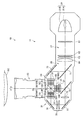
- FIG. 3 is a diagram illustrating a configuration of a light projection unit of the projector according to the embodiment of the invention.
- the figure which showed the focus adjustment part typically with the liquid crystal panel.
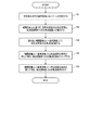
- the block diagram which showed the function structure of the projector. 6 is a flowchart showing a focus adjustment operation.
- (A) And (B) is a figure where it uses for description of the liquid lens applied to a focus adjustment part.
- FIG. 1 is a diagram showing a configuration of a light projection unit 11 of a projector 10 according to an embodiment of the present invention.
- the projector 10 includes a light projection unit 11 that projects an image on a projection surface SC, and functions as an image display device that displays an image on the projection surface SC.
- the projection surface SC that can be projected by the projector 10 is not limited to a flat surface but is a surface having various shapes including a curved surface and an uneven surface.
- FIG. 1 shows a case where the projection surface SC is a curved surface.
- the projection target projected by the projector 10 may be a screen or a wall surface, or may be the surface of a three-dimensional object.
- the projection target is a curved projection plane SC.
- the installation state of the projector 10 may be a floor-standing installation in which the floor is placed in front of the projection screen SC, or may be a ceiling-mounted installation suspended from the ceiling, and is not particularly limited.
- the light projection unit 11 includes a light source device 21, a modulation unit 23, and a projection optical system 25.
- the light projection unit 11 further includes a light source side optical system 27, a separation optical system 29, a relay optical system 31, and a combining optical system 33.
- the light source device (light source) 21 includes a light emitting unit 21A and a reflector 21B.
- a halogen lamp, an ultrahigh pressure mercury lamp, a metal halide lamp, or the like can be used as the light emitting unit 21A.
- the reflector 21B includes a parabolic mirror, for example. Radial light emitted from the light emitting unit 21A is reflected by the reflector 21B and converted into parallel light.
- the reflector 21 ⁇ / b> B emits light from the light emitting unit 21 ⁇ / b> A toward the light source side optical system 27.
- the light source device 21 is not limited to a lamp, and may be a solid light source such as an LED (Light Emitting Diode) or a laser light source, or another light source.
- the modulation unit 23 includes a liquid crystal panel 50 that functions as a light modulation device that modulates light (light source light) from the light source device (light source) 21.
- the liquid crystal panel 50 is a transmissive liquid crystal panel, and is provided corresponding to each of the three primary colors of RGB. That is, the liquid crystal panel 50 includes a liquid crystal panel 50R that modulates red (R) color light, a liquid crystal panel 50G that modulates green (G) color light, and a liquid crystal panel 50B that modulates blue (B) color light.
- the modulation unit 23 is not limited to a transmissive liquid crystal panel, and other light modulation devices such as a reflective liquid crystal panel and a digital mirror device may be employed. Further, the configuration is not limited to a configuration including a plurality of light modulation devices, and a configuration including only one light modulation device may be employed.
- red color light is appropriately referred to as red light
- green color light is appropriately referred to as green light
- blue color light is appropriately referred to as blue light
- the liquid crystal panel 50R is a liquid crystal panel for red light
- the liquid crystal panel 50G is a liquid crystal panel for green light
- the liquid crystal panel 50B is a liquid crystal panel for blue light
- the liquid crystal panels 50R, 50G, and 50B are referred to as the liquid crystal panel 50 when it is not necessary to distinguish between them.
- the light source side optical system 27 emits light (light source light) incident from the light source device (light source) 21 with a uniform illuminance distribution.
- the light source side optical system 27 includes a first lens 61, a second lens 62, a polarization conversion element 63, and a superimposing lens 64 disposed on the optical path of the light source device (light source) 21.
- the first lens 61 and the second lens 62 are array lenses in which a plurality of microlenses are arranged in a matrix.
- the first lens 61 divides the light emitted from the light source device 21 into partial light beams and emits them.
- the second lens 62 forms an image of each microlens of the first lens 61 together with the superimposing lens 64 on each of the liquid crystal panels 50R, 50G, and 50B.
- the polarization conversion element 63 is disposed between the second lens 62 and the superimposing lens 64.
- the polarization conversion element 63 converts light including two types of polarization components emitted from the second lens 62 into one type of polarized light that can be modulated by the liquid crystal panels 50R, 50G, and 50B.
- the polarized light which is consumed as heat in the absence of the polarization conversion element 63, is used as light that can be modulated by the liquid crystal panel 50, thereby improving the light use efficiency.
- the separation optical system 29 separates the light from the light source side optical system 27 into light of three colors, red light (R), green light (G), and blue light (B).
- the separation optical system 29 of this embodiment includes two dichroic mirrors 71 and 72 and a reflection mirror 73.
- the dichroic mirror 71 transmits red light and green light and reflects blue light.
- the reflection mirror 73 guides the blue light to the liquid crystal panel 50B of the modulation unit 23 by reflecting the blue light reflected by the dichroic mirror 71.
- the dichroic mirror 72 guides the green light to the liquid crystal panel 50 ⁇ / b> G of the modulation unit 23 by transmitting the red light and reflecting the green light out of the light from the dichroic mirror 71.
- the relay optical system 31 includes an incident side lens 75, a relay lens 76, and reflection mirrors 77 and 78, and guides the red light transmitted through the dichroic mirror 72 to the liquid crystal panel 50R for red light.
- the relay optical system 31 has described the case where the red light of the three color lights is guided.
- the present invention is not limited to this. For example, by changing the functions of the dichroic mirrors 71 and 72, the blue light and the green light are guided. It is good also as a structure.
- the modulation unit 23 modulates incident light based on image data (image signal).
- the modulation unit 23 includes three incident-side polarizing plates 81 on which each light from the separation optical system 29 and the relay optical system 31 enters, and three liquid crystal panels 50R disposed on the output side of the incident-side polarizing plates 81, 50G and 50B. Further, the modulation unit 23 includes three emission-side polarizing plates 82 disposed on the emission side of each liquid crystal panel 50R, 50G, 50B.
- the incident-side polarizing plate 81 transmits only polarized light in a certain direction out of each light separated by the separation optical system 29 and absorbs other light.
- the output side polarizing plate 82 transmits only polarized light in a predetermined direction out of the modulated light output from the liquid crystal panel 50 and absorbs other light.
- the incident side polarizing plate 81 and the outgoing side polarizing plate 82 are arranged so that the directions of the polarization axes thereof are orthogonal to each other.
- a field lens 91 is disposed on the incident side of the incident side polarizing plate 81.
- the field lens 91 has an optical function of converting each partial light beam emitted from the second lens 62 into a light beam parallel to the central axis (principal light beam). That is, each light separated by the separation optical system 29 passes through the field lens 91 and the incident-side polarizing plate 81 and enters each of the liquid crystal panels 50R, 50G, and 50B.
- the liquid crystal panels 50R, 50G, and 50B are, for example, active matrix transmissive liquid crystal panels using polysilicon TFTs (Thin Film Transistors) as switching elements, and are also referred to as TFT liquid crystals.
- the liquid crystal panels 50R, 50G, and 50B modulate each incident color light according to image information (signal) for each color light, and input the modulated light for each color light to the combining optical system 33 via the output side polarizing plate 82.
- the synthesizing optical system 33 includes a dichroic prism 33A, and synthesizes the three colors of modulated light emitted from the liquid crystal panels 50R, 50G, and 50B via the emitting side polarizing plate 82.
- the dichroic prism 33A is, for example, a cross dichroic prism in which a dielectric multilayer film that reflects red light and a dielectric multilayer film that reflects blue light are arranged in an approximately X shape along the interface of four right-angle prisms. is there.
- the projection optical system 25 includes a projection lens (not shown) on the emission side of the synthesis optical system 33, and expands the full-color light synthesized by the synthesis optical system 33 via the projection lens and emits it to the projection plane SC.
- the projection optical system 25 can adjust the focus by changing the position of the projection lens.
- the projector 10 includes a focus adjustment unit (focus adjustment unit) 100 that can adjust the focus for each modulated light region between the liquid crystal panels 50R, 50G, and 50B and the combining optical system 33.
- the focus adjustment unit 100 is a lens array including microlenses whose refractive index can be changed for each region of modulated light passing through the liquid crystal panels 50R, 50G, and 50B. More specifically, each microlens is a liquid crystal. It is the liquid crystal lens array comprised by the lens. Each microlens is arranged in a matrix with several pixels of the liquid crystal panel 50 (50R, 50G, 50B) as one section. Each micro lens may be provided for each pixel of the liquid crystal panel 50.
- the focal point can be changed for each microlens through which the modulated light passes, with respect to the modulated light passing through the liquid crystal panel 50.
- the microlens since the microlens is arranged for each section of the several pixels of the liquid crystal panel 50, the focus can be adjusted for each modulated light passing through the section. In other words, the focus of each modulated light can be adjusted for each area when the modulated light is divided into a plurality of predetermined areas.
- the configuration is not limited to the configuration in which the refractive indexes of the plurality of microlenses are individually variable, and the configuration may be such that the microlenses are allocated to a plurality of groups, and the focus is adjusted by controlling the refractive indexes of the microlenses for each group.
- the predetermined plurality of regions are regions that are regularly divided in a matrix in two directions corresponding to the horizontal direction and the vertical direction of the liquid crystal panel 50.
- the focal point can be adjusted for each region aligned in the horizontal direction and the vertical direction with respect to the projection surface SC.
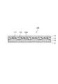
- FIG. 2 is a diagram illustrating a cross-sectional structure of the focus adjustment unit 100.
- the focus adjustment unit 100 is a pair of transparent substrates 111 and 112 made of a transparent material such as glass (hereinafter, one transparent substrate 111 is referred to as a “first substrate 111”, and the other transparent substrate 112 is referred to as a “second substrate 112”. )
- stripe-shaped first electrodes 115 each including a plurality of strip-like electrodes extending in the horizontal direction of the respective liquid crystal panels 50 and arranged in parallel to each other are provided.
- the first electrode 115 is made of a transparent conductive film such as ITO (Indium Tin Oxide).
- a lens-shaped layer 116 made of a resin having high light transmittance is provided on the entire inner surface of the second substrate 112.
- the lens shape layer 116 gives the liquid crystal layer 113 a lens shape, and the lens shape layer 116 has a curved surface so that the liquid crystal layer 113 sandwiched between the first substrate 111 and the second substrate 112 has a convex lens shape.
- a plurality of recesses 116A are provided.
- a striped second electrode 117 is provided that includes a plurality of strip-shaped electrodes that extend in the vertical direction of the liquid crystal panel 50 and are arranged in parallel to each other.
- the second electrode 117 is formed along the recess 116 ⁇ / b> A of the lens shape layer 116. Similarly to the first electrode 115, the second electrode 117 is also made of a transparent conductive film such as ITO. As the liquid crystal material constituting the liquid crystal layer 113, either a material having a positive dielectric anisotropy or a material having a negative dielectric anisotropy is applicable.
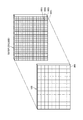
- the focus adjustment unit 100 is driven in a so-called simple matrix type for each region RR divided in the direction corresponding to the horizontal direction and the vertical direction of the liquid crystal panel.
- the refractive index of each region RR can be varied.
- FIG. 3 shows a case where each region RR of the focus adjustment unit 100 is formed for each region corresponding to 4 pixels (2 pixels in the horizontal direction and 2 pixels in the vertical direction) of the liquid crystal panel 50.
- reference numeral RR ⁇ b> 1 indicates an area of one pixel of the liquid crystal panel 50.
- the focus adjusting unit 100 When no voltage is applied (no voltage applied state), the focus adjusting unit 100 is configured so that the liquid crystal material and the lens-shaped layer 116 have a refractive index that matches the refractive index of the lens-shaped layer 116. A resin material is selected. For this reason, when there is no need to change the focal point for each modulated light region RR, by applying no voltage, light is not refracted at the interface between the liquid crystal layer 113 and the lens shape layer 116, and the focal point is changed. Not. On the other hand, when a voltage is applied between the first electrode 115 and the second electrode 117, the alignment state of the liquid crystal layer 26 changes according to the applied voltage. Thus, the refractive index at the interface between the liquid crystal layer 113 and the lens shape layer 116 can be adjusted by adjusting the voltage to be applied.
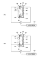
- the focus adjustment unit 100 may be formed as a single component, or may be configured as an integral component integrated with surrounding components.
- FIG. 4A shows an example when the focus adjustment unit 100 is formed by a single component
- FIGS. 4B and 4C show an example when the focus adjustment unit 100 is configured integrally with surrounding components. Yes.
- the focus adjustment unit 100 is formed as a single component, as shown in FIG. 4 (A), the focus adjustment unit 100 is formed using a gap between the exit-side polarizing plate 82 and the dichroic prism 33A of the conventional projector. It becomes easy to arrange.
- FIG. 4B shows a case where the focus adjustment unit 100 is configured integrally with the emission side polarizing plate 82.
- the output side polarizing plate 82 is also integrally formed on the output side surface of the liquid crystal panel 50.
- the arrangement space can be minimized and the number of components can be reduced.
- FIG. 4C shows a case where the focus adjustment unit 100 is configured integrally with the incident side surface of the dichroic prism 33A. Also in this case, the arrangement space can be reduced as compared with the case shown in FIG.
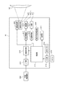
- FIG. 5 is a block diagram illustrating a functional configuration of the projector 10.
- the projector 10 includes an interface (I / F) unit 210 to which an external image supply device 200 is connected, and inputs various image data (including image signals) via the I / F unit 210.
- the image supply device 200 is an image reproduction device such as a DVD player, a broadcast reception device such as a digital TV tuner, and an image output device such as a video game machine or a personal computer. Further, the image supply device 200 may be a communication device that wirelessly communicates with a personal computer or the like to receive image data.
- the image data input from the image supply apparatus 200 to the projector 10 may be any data (signal) of a moving image or a still image. Further, the projector 10 may read out image data stored in the storage unit 211 in the projector 10 or an externally connected storage medium, and display an image on the projection screen SC based on the image data.
- the projector 10 includes a storage unit 211, a control unit (control means) 212, an input unit 213, an operation panel 214, a remote controller 215, an image processing unit 216, a display drive unit 217, And a light source controller 218.
- the storage unit 211 stores various data, programs, and the like that are processed by the projector 10.
- the storage unit 211 is, for example, a RAM (Random Access Memory), a register, an HDD (Hard Disk Drive), or an SSD (Solid State Drive).
- the control unit 212 controls each unit of the projector 10 by executing a program stored in the storage unit 211.
- the input unit 213 inputs a user instruction via the operation panel 214 and the remote controller 215 and notifies the control unit 212 of it. That is, the control unit 212 controls each unit of the projector 10 based on a user instruction or the like.
- the image processing unit 216 manages image processing on the input image data under the control of the control unit 212. For example, the image processing unit 216 appropriately performs resizing processing, keystone correction, and the like so that an image corresponding to the image data is displayed on the projection surface SC with an appropriate size. Further, the image processing unit 216 outputs an image signal representing the gradation of each pixel of the liquid crystal panels 50R, 50G, and 50B included in the light projection unit 11 for each RGB based on the image subjected to the image processing.
- the display drive unit 217 drives the liquid crystal panels 50R, 50G, and 50B based on the image signal output from the image processing unit 216, sets the gradation of each pixel, and displays a frame (screen) on the liquid crystal panels 50R, 50G, and 50B. Draw an image in units.
- the light source control unit 218 drives the light source device 21 to turn on and controls the amount of light of the light source device 21 under the control of the control unit 212.
- the projector 10 includes a focus variable drive unit 220 that drives the focus adjustment unit 100 and a distance measurement unit (distance measurement unit) 222 that measures the distance to the projection surface SC.
- the focus variable drive unit 220 drives the focus adjustment unit 100 with voltage under the control of the control unit 212. Accordingly, the focus varying drive unit 220 varies the focus for each modulated light in each region RR (FIG. 3) obtained by dividing the modulated light passing through the liquid crystal panel 50 in the horizontal direction and the vertical direction of the liquid crystal panel 50.
- the distance measuring unit 222 measures the distance to the projection area where the modulated light in each area RR is projected under the control of the control unit 212.
- the distance measuring unit 222 of the present embodiment is applied with a laser distance meter and measures the separation distance from the projector 10 for each projection region (for each region corresponding to each region RR on the projection surface SC).
- the distance measuring unit 22 is not limited to the laser distance meter, and a wide range of known distance measuring devices such as a configuration for measuring distance using a plurality of cameras can be widely used.
- the control unit 212 uses the distance measuring unit 222 to scan the entire projection surface SC with laser light, so that for each modulated light region RR, the separation distance Lk to the projection region where the modulated light in each region RR is projected. Are respectively measured (step S1).
- the value k is an integer from 1 to n
- the value n is the number of projection areas onto which the modulated light of each area RR is projected, that is, an area (area RR) whose focus can be adjusted separately. ).
- the control unit 212 causes the storage unit 211 to store information on the measured separation distance Lk.
- the separation distance Lk may be an average value of separation distances at a plurality of locations in the projection area where the modulated light of each region RR is projected, or may be a separation distance of a representative position (for example, a center position) in the projection area. .
- the control unit 212 starts focus adjustment based on the measured separation distance Lk (step S2).
- This focus adjustment includes focus adjustment of the projection optical system 25 and focus adjustment of the focus adjustment unit.
- the control unit 212 specifies the shortest separation distance Lk among the measured separation distances Lk, and the focal point of the projection optical system 25 is set to the shortest separation distance Lk (hereinafter referred to as “reference distance L0”). Is adjusted (step S3).
- the control unit 212 performs control for automatically adjusting the focus of the projection optical system 25.
- the user may manually adjust the focus of the projection optical system 25. In this case, it is preferable to perform guidance so as to focus on the shortest separation distance Lk by image display or sound.
- the focus adjustment by the focus adjustment unit 100 since the focus of the projection optical system 25 is focused on the closest part of the projection surface SC, the focus adjustment by the focus adjustment unit 100 only needs to be adjusted to the side of increasing the focus. In this case, at the time of focus adjustment of the projection optical system 25 shown in step S2, the focus adjustment unit 100 is in a state where the focus is the shortest (in this configuration, no voltage is applied and no refraction occurs). Thus, a wide focus adjustment range can be secured.
- the control unit 212 When performing the focus adjustment by the focus adjustment unit 100, the control unit 212 obtains a focus adjustment distance (separation distance Lk ⁇ reference distance L0 ⁇ focus depth) and specifies a voltage necessary to adjust the focus adjustment distance. Then, the control unit 212 applies the specified voltage to the predetermined region RR corresponding to the focus adjustment target region by the focus variable drive unit 220. As a result, the focus is adjusted appropriately.
- a focus adjustment distance separation distance Lk ⁇ reference distance L0 ⁇ focus depth
- the voltage necessary for adjusting the focus adjustment distance is specified by, for example, storing table data in which the focus adjustment distance and the voltage are associated with each other in advance in the storage unit 211, and the control unit 212 selects the table.
- the voltage may be specified based on the data.
- This focus adjustment operation may be started automatically by the control unit 212 at a predetermined setting performed after the projector 10 is installed, or may be started by the control unit 212 when a user instruction is given.
- the projector 10 projects the light source device 21, the modulation unit 23 that modulates the light source light emitted from the light source device 21, and the modulation light that is modulated by the modulation unit 23. And an optical system 25. Furthermore, the projector 10 includes a focus adjustment unit 100 that can adjust the focus for each region of the modulated light. Thereby, defocus due to the shape or the like of the projection surface SC is suppressed, and projection is possible in a state in which the surface is focused on a curved surface or an uneven surface.
- the modulation unit 23 is divided into a plurality of regions, and the focus adjustment unit 100 performs focus adjustment for each of the divided regions. Thereby, focus adjustment can be performed for each of the divided regions of the modulation unit 23 to suppress defocus due to the shape of the projection surface SC or the like.
- the focus adjustment unit 100 uses a liquid crystal lens that performs focus adjustment for each divided region of the modulation unit 23, it is possible to suppress defocus due to the shape or the like of the projection surface SC using the liquid crystal lens. . For this reason, a known liquid crystal lens technique can be applied.
- the focus adjustment unit 100 since the focus adjustment unit 100 is disposed between the modulation unit 23 and the projection optical system 25, the focus adjustment unit 100 can be disposed using an empty space between the modulation unit 23 and the projection optical system 25. That is, it becomes easy to arrange the focus adjustment unit 100 using the configuration of the conventional projector including the modulation unit 23 and the projection optical system 25 as it is.
- the projector 10 of the present embodiment includes the liquid crystal panels 50R, 50G, and 50B that function as a plurality of light modulation devices, and the combining optical system 33 that combines the modulated light from the liquid crystal panels 50R, 50G, and 50B.
- the focus adjustment unit 100 is disposed between the combining optical system 33 and the liquid crystal panels 50R, 50G, and 50B. As a result, the focus adjustment unit 100 can be arranged using a space that is open between the plurality of liquid crystal panels 50R, 50G, and 50B included in the conventional projector or the like and the combining optical system 33.
- the so-called three-plate projector can suppress the defocus due to the shape of the projection surface SC and the like, and can perform projection in a state where the curved surface or the uneven surface is in focus.
- it has a combining optical system 33 that combines the modulated light from the liquid crystal panels 50R, 50G, and 50B, and the plurality of focus adjustment units 100 are disposed between the liquid crystal panels 50R, 50G, and 50B and the combining optical system 33. Is done. Accordingly, the configuration of a so-called three-plate projector can be used as it is, so that defocus can be suppressed and projection can be performed while focusing on a curved surface or an uneven surface.
- the focus adjusting unit 100 is configured as a lens array including a plurality of microlenses. Accordingly, a configuration in which focus adjustment is performed with several pixels of each of the liquid crystal panels 50R, 50G, and 50B as one section, or a configuration in which focus adjustment is performed for each pixel of each of the liquid crystal panels 50R, 50G, and 50B is possible. Therefore, high-precision focus adjustment in units of several pixels or one pixel is possible, which is advantageous for improving the quality of a projected image.
- the projector 10 includes a distance measurement unit 222 and a control unit 212.
- the distance measuring unit 222 measures, for each modulated light region RR modulated by the modulating unit 23, a separation distance Lk to the projection region on which the modulated light in each region RR is projected.
- the control unit 212 causes the focus adjustment unit 100 to perform focus adjustment for each modulated light region RR based on the measured separation distance Lk.
- control unit 212 adjusts the focal point of each modulated light region RR based on the measured separation distance Lk, by adjusting the focus by the projection optical system 25 and adjusting the focal point of each modulated light region RR by the focus adjusting unit 100. To the projection area.
- the focus of each modulated light region is adjusted to the projection region by the focus adjustment by the projection optical system 25 and the focus adjustment by the focus adjustment unit 100 for each region RR of the modulated light. It is possible to project in a state in which the resulting defocus is suppressed and focused on a curved surface or an uneven surface.
- control unit 212 is configured to adjust the focal point of the modulated light region RR by the reference distance L0 by the focus adjustment by the projection optical system 25 based on the reference distance L0 set based on the measured separation distance Lk.
- the focus adjustment unit 100 adjusts the focus of each modulated light region RR to the projection region by adjusting the focus of each modulated light region RR. .
- the focus adjustment by the focus adjustment unit 100 only needs to be adjusted to the side of increasing the focus.
- the distance measurement unit 222 separates each modulation light region RR modulated by the modulation unit 23 from the projection region where the modulated light in each region RR is projected. The distance Lk is measured. Then, the control unit 212 performs focus adjustment by the projection optical system 25 and focus adjustment for each modulated light region RR by the focus adjustment unit 100 based on the measured separation distance Lk. As a result, defocus due to the shape or the like of the projection surface SC is suppressed, and projection can be performed while focusing on a curved surface or an uneven surface.
- the control unit 212 sets the focus for each region RR of the modulated light based on the reference distance L0 set based on the measured separation distance Lk by the focus adjustment by the projection optical system 25. It is adjusted to a position separated by a distance L0. Based on the difference between the reference distance L0 and the measured separation distance Lk, the focus adjustment unit 100 adjusts the focus of each modulated light region RR to the projection region by adjusting the focus of each modulated light region RR. As a result, it is possible to appropriately suppress the focus adjustment by the projection optical system 25 and the focus adjustment by the focus adjustment unit 100 to suppress defocus due to the shape or the like of the projection surface SC.
- the reference distance L0 may be set to the longest distance among the measured separation distances Lk, and the focus adjustment performed by the focus adjustment unit 100 may be adjusted to the side that shortens the focus.
- the reference distance L0 may be set to an intermediate distance among the measured separation distances Lk, and the focus adjustment by the focus adjustment unit 100 may be performed using the intermediate distance as a reference.
- the embodiment described above shows a preferred embodiment of the present invention, does not limit the present invention, and various modifications can be made without departing from the gist of the present invention.
- the case where the liquid crystal lens that is an electric focus variable lens is used as the focus adjustment unit 100 has been described.
- the present invention is not limited to this, and other electric focus variable lenses such as a liquid lens are used. There may be.
- the liquid lens is a lens having a variable curvature.
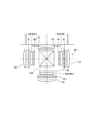
- the focus adjustment unit 100 is configured by a liquid lens array in which microlenses arranged in a matrix form are liquid lenses. Is preferred. A configuration example of the liquid lens in this case will be described with reference to FIGS. 7A and 7B.
- the liquid lens 300 includes a sealing member (container) 310 made of a transparent material in which a recess 301 is formed.
- a first electrode 312 and a second electrode 314 are formed on inner surfaces M1 and M2 that are separated from each other in the recess 301, respectively.
- an oil droplet 316 and an aqueous electrolyte solution 318 that covers the oil droplet 316 are provided so as to be in contact with the electrodes 312 and 314.
- a transparent electrode 320 is provided on the facing surface M4 facing the bottom surface M3 of the recess 301 of the sealing member 310.
- the first electrode 312, the second electrode 314, and the transparent electrode 320 are made of a transparent conductive film such as ITO.
- Various voltages are applied to the first electrode 312, the second electrode 314, and the transparent electrode 320 by the focus variable drive unit 220.
- this voltage is supplied with the waveform of a sine wave, for example.
- the focus changing drive unit 220 draws the electrolytic solution 318 between the first and second electrodes 312 and 314 by changing the applied voltage under the control of the control unit 212.
- the curvature of the oil droplet 316 is made relatively small, or as shown in FIG. 7 (B), the curvature of the oil droplet 316 is made relatively large. Can do. Due to this change in curvature, the refractive index of the liquid lens changes, and the focal point can be adjusted. Even with the configuration using this liquid lens, the same layout as in the above embodiment is possible, and various effects similar to those in the above embodiment can be obtained.
- the liquid lens is not limited to the above-described configuration, and a known configuration can be widely applied.
- other electric focus variable lenses such as a gel variable lens and a lens using an electro-optic crystal can be applied to the focus adjustment unit 100.
- the configuration in which the three focus adjustment units 100 are provided so as to correspond to the liquid crystal panels 50R, 50G, and 50B, respectively, but a configuration in which only one focus adjustment unit 100 is provided may be employed.
- the focus adjustment unit 100 may be disposed between the dichroic prism 33 ⁇ / b> A and the projection optical system 25.
- the configuration of the focus adjustment unit 100 may be formed as a single component, or may be configured integrally with the dichroic prism 33A.
- the focus adjustment unit 100 may be disposed in the projection optical system 25.
- the focus adjustment unit 100 may be mounted on the emission side of the projection optical system 25 (outside the projector 10), or the focus adjustment unit 100 may be provided inside the optical system of the projection optical system 25.
- the configuration of the projector 10 shown in FIG. 5 and the like shows a functional configuration, and does not limit a specific mounting form. That is, it is not always necessary to mount hardware corresponding to each function unit individually, and it is of course possible to adopt a configuration in which the functions of a plurality of function units are realized by one processor executing a program.
- a part of the function realized by software may be realized by hardware, or a part of the function realized by hardware may be realized by software.
- DESCRIPTION OF SYMBOLS 10 ... Projector, 11 ... Light projection part, 21 ... Light source device (light source), 23 ... Modulation part (light modulation device), 25 ... Projection optical system, 27 ... Light source side optical system, 29 ... Separation optical system, 31 ... Relay Optical system 33... Synthetic optical system, 100... Focus adjustment unit (focus adjustment unit), 212... Control unit (control unit), 222 ... Distance measurement unit (distance measurement unit), SC.
Landscapes
- Physics & Mathematics (AREA)
- Engineering & Computer Science (AREA)
- General Physics & Mathematics (AREA)
- Multimedia (AREA)
- Signal Processing (AREA)
- Optics & Photonics (AREA)
- Computer Vision & Pattern Recognition (AREA)
- Projection Apparatus (AREA)
- Transforming Electric Information Into Light Information (AREA)
- Liquid Crystal (AREA)
Abstract
Selon l'invention, des écarts de point focal dus à des facteurs comme la forme d'une surface de projection sont minimisés, et des projections à mise au point peuvent être réalisées sur une surface incurvée, une surface irrégulière, etc. Un projecteur (10) est caractérisé en ce qu'il comprend un dispositif de source de lumière (21), une unité de modulation (23) qui fonctionne comme un dispositif de modulation optique pour la modulation de la lumière de source de lumière émise par un dispositif de source de lumière (21), un système optique de projection (25) pour la projection de lumière modulée qui a été modulée par l'unité de modulation (23), et une unité de réglage de point focal (100) pouvant régler le point focal dans chaque zone de lumière modulée.
Priority Applications (2)
| Application Number | Priority Date | Filing Date | Title |
|---|---|---|---|
| CN201780008110.4A CN108496112B (zh) | 2016-01-26 | 2017-01-18 | 投影仪以及投影仪的控制方法 |
| US16/070,027 US20190018306A1 (en) | 2016-01-26 | 2017-01-18 | Projector and method for controlling projector |
Applications Claiming Priority (2)
| Application Number | Priority Date | Filing Date | Title |
|---|---|---|---|
| JP2016012122A JP6679950B2 (ja) | 2016-01-26 | 2016-01-26 | プロジェクター、及びプロジェクターの制御方法 |
| JP2016-012122 | 2016-01-26 |
Publications (1)
| Publication Number | Publication Date |
|---|---|
| WO2017130817A1 true WO2017130817A1 (fr) | 2017-08-03 |
Family
ID=59397769
Family Applications (1)
| Application Number | Title | Priority Date | Filing Date |
|---|---|---|---|
| PCT/JP2017/001568 WO2017130817A1 (fr) | 2016-01-26 | 2017-01-18 | Projecteur et procédé de commande de projecteur |
Country Status (4)
| Country | Link |
|---|---|
| US (1) | US20190018306A1 (fr) |
| JP (1) | JP6679950B2 (fr) |
| CN (1) | CN108496112B (fr) |
| WO (1) | WO2017130817A1 (fr) |
Families Citing this family (2)
| Publication number | Priority date | Publication date | Assignee | Title |
|---|---|---|---|---|
| WO2017134781A1 (fr) * | 2016-02-03 | 2017-08-10 | Necディスプレイソリューションズ株式会社 | Projecteur et procédé de réglage de mise au point |
| CN110784698B (zh) * | 2019-10-31 | 2021-09-21 | 峰米(北京)科技有限公司 | 一种热失焦补偿方法、存储介质和投影设备 |
Citations (3)
| Publication number | Priority date | Publication date | Assignee | Title |
|---|---|---|---|---|
| JPH07261072A (ja) * | 1994-03-23 | 1995-10-13 | Rohm Co Ltd | 自動焦点プロジェクター |
| JP2002214579A (ja) * | 2001-01-19 | 2002-07-31 | Ricoh Co Ltd | 画像表示装置 |
| JP2016161746A (ja) * | 2015-03-02 | 2016-09-05 | セイコーエプソン株式会社 | 画像表示装置、プロジェクター及び透過型表示装置 |
Family Cites Families (20)
| Publication number | Priority date | Publication date | Assignee | Title |
|---|---|---|---|---|
| US6729734B2 (en) * | 2002-04-01 | 2004-05-04 | Hewlett-Packard Development Company, L.P. | System for enhancing the quality of an image |
| WO2003104853A2 (fr) * | 2002-06-10 | 2003-12-18 | Reveo, Inc | Repartiteur optique pouvant etre mis a l'echelle et produit a l'echelle industrielle comprenant des cellules a cristaux liquides |
| US20050259226A1 (en) * | 2004-05-20 | 2005-11-24 | Gilg Thomas J | Methods and apparatuses for presenting an image |
| JP2006317795A (ja) * | 2005-05-13 | 2006-11-24 | Toshiba Corp | 投射装置と投射装置の測距方法 |
| US7486341B2 (en) * | 2005-11-03 | 2009-02-03 | University Of Central Florida Research Foundation, Inc. | Head mounted display with eye accommodation having 3-D image producing system consisting of, for each eye, one single planar display screen, one single planar tunable focus LC micro-lens array, one single planar black mask and bias lens |
| US20100201952A1 (en) * | 2009-02-06 | 2010-08-12 | Seiko Epson Corporation | Projector |
| JP2010243545A (ja) * | 2009-04-01 | 2010-10-28 | Seiko Epson Corp | プロジェクターの光変調素子位置調整方法およびプロジェクター |
| US20120147342A1 (en) * | 2010-12-14 | 2012-06-14 | National Chiao Tung University | Projection apparatus |
| JP2012170007A (ja) * | 2011-02-16 | 2012-09-06 | Sanyo Electric Co Ltd | 投写型映像表示装置及び画像調整方法 |
| DE102011076083A1 (de) * | 2011-05-18 | 2012-11-22 | Fraunhofer-Gesellschaft zur Förderung der angewandten Forschung e.V. | Projektionsdisplay und Verfahren zum Anzeigen eines Gesamtbildes für Projektionsfreiformflächen oder verkippte Projektionsflächen |
| JP5533798B2 (ja) * | 2011-07-04 | 2014-06-25 | セイコーエプソン株式会社 | 投写光学系及びこれを備えるプロジェクター |
| JP6089424B2 (ja) * | 2012-03-21 | 2017-03-08 | セイコーエプソン株式会社 | 画像処理装置、プロジェクター、およびプロジェクターの制御方法 |
| WO2014115884A1 (fr) * | 2013-01-28 | 2014-07-31 | 株式会社Jvcケンウッド | Appareil de projection, procédé de correction d'image et programme |
| JP6149543B2 (ja) * | 2013-06-28 | 2017-06-21 | アイシン・エィ・ダブリュ株式会社 | ヘッドアップディスプレイ装置 |
| JP6138634B2 (ja) * | 2013-08-29 | 2017-05-31 | アイシン・エィ・ダブリュ株式会社 | ヘッドアップディスプレイ装置 |
| JP6287437B2 (ja) * | 2014-03-26 | 2018-03-07 | セイコーエプソン株式会社 | プロジェクター |
| US10146180B2 (en) * | 2014-07-04 | 2018-12-04 | Seereal Technologies S.A. | Projection display and method for displaying at least one of two-dimensional and three-dimensional scene or of content |
| WO2016047824A1 (fr) * | 2014-09-25 | 2016-03-31 | 엘지전자 주식회사 | Dispositif de projection d'informations d'image, et procédé de commande de dispositif de projection |
| JP2016109963A (ja) * | 2014-12-09 | 2016-06-20 | 株式会社リコー | 画像投射装置及び焦点距離算出方法 |
| WO2017085802A1 (fr) * | 2015-11-18 | 2017-05-26 | 日立マクセル株式会社 | Dispositif de projection d'images |
-
2016
- 2016-01-26 JP JP2016012122A patent/JP6679950B2/ja active Active
-
2017
- 2017-01-18 US US16/070,027 patent/US20190018306A1/en not_active Abandoned
- 2017-01-18 CN CN201780008110.4A patent/CN108496112B/zh active Active
- 2017-01-18 WO PCT/JP2017/001568 patent/WO2017130817A1/fr active Application Filing
Patent Citations (3)
| Publication number | Priority date | Publication date | Assignee | Title |
|---|---|---|---|---|
| JPH07261072A (ja) * | 1994-03-23 | 1995-10-13 | Rohm Co Ltd | 自動焦点プロジェクター |
| JP2002214579A (ja) * | 2001-01-19 | 2002-07-31 | Ricoh Co Ltd | 画像表示装置 |
| JP2016161746A (ja) * | 2015-03-02 | 2016-09-05 | セイコーエプソン株式会社 | 画像表示装置、プロジェクター及び透過型表示装置 |
Also Published As
| Publication number | Publication date |
|---|---|
| JP2017134144A (ja) | 2017-08-03 |
| JP6679950B2 (ja) | 2020-04-15 |
| US20190018306A1 (en) | 2019-01-17 |
| CN108496112A (zh) | 2018-09-04 |
| CN108496112B (zh) | 2021-03-12 |
Similar Documents
| Publication | Publication Date | Title |
|---|---|---|
| US20080055550A1 (en) | Microprojector | |
| JP6172773B2 (ja) | プロジェクタ及び画像表示方法 | |
| US9667927B2 (en) | Projector | |
| RU2629889C1 (ru) | Устройство отображения изображения и способ управления устройством отображения изображения | |
| WO2017130817A1 (fr) | Projecteur et procédé de commande de projecteur | |
| JPWO2020026706A1 (ja) | 光学モジュール、投射型画像表示装置、光学モジュールの製造方法 | |
| US8025411B2 (en) | Liquid crystal panel and projector using the same | |
| JP2008268253A (ja) | 液晶表示装置および液晶表示装置の駆動方法ならびに映像表示装置 | |
| US9039186B2 (en) | Projector having tilted transmissive substrate and multicolor pixel modulator | |
| JP2006010868A (ja) | マイクロレンズアレイ、液晶表示装置、投射型表示装置 | |
| CN215219403U (zh) | 投影装置、投影镜头组件以及投影系统 | |
| JP2016181865A (ja) | 映像処理装置、表示装置、及び、映像処理方法 | |
| US8182098B2 (en) | Projection optical system | |
| CN219958062U (zh) | 投影系统 | |
| JP2009210765A (ja) | プロジェクタ | |
| US9979940B2 (en) | Projector and method for controlling projector | |
| JP2017129730A (ja) | プロジェクター | |
| JP2023009775A (ja) | プロジェクター | |
| JP2007264340A (ja) | 画像表示装置及びプロジェクタ | |
| JP2010054654A (ja) | 電気光学装置、及び該電気光学装置を備えるプロジェクタ | |
| JP5217207B2 (ja) | プロジェクタ | |
| KR20110032984A (ko) | 광 스캐너 패키지 및 그를 이용한 레이저 디스플레이 시스템 | |
| JP5891742B2 (ja) | 光学ユニット及びプロジェクター | |
| JP2011248308A (ja) | 投写型映像表示装置 | |
| KR20080024914A (ko) | 다이크로익 미러 홀딩 구조 및 이를 구비한 마이크로프로젝터 |
Legal Events
| Date | Code | Title | Description |
|---|---|---|---|
| 121 | Ep: the epo has been informed by wipo that ep was designated in this application |
Ref document number: 17744047 Country of ref document: EP Kind code of ref document: A1 |
|
| NENP | Non-entry into the national phase |
Ref country code: DE |
|
| 122 | Ep: pct application non-entry in european phase |
Ref document number: 17744047 Country of ref document: EP Kind code of ref document: A1 |