WO2017130675A1 - 制御装置 - Google Patents
制御装置 Download PDFInfo
- Publication number
- WO2017130675A1 WO2017130675A1 PCT/JP2017/000373 JP2017000373W WO2017130675A1 WO 2017130675 A1 WO2017130675 A1 WO 2017130675A1 JP 2017000373 W JP2017000373 W JP 2017000373W WO 2017130675 A1 WO2017130675 A1 WO 2017130675A1
- Authority
- WO
- WIPO (PCT)
- Prior art keywords
- air
- humidity
- pressure
- engine
- throttle
- Prior art date
- Legal status (The legal status is an assumption and is not a legal conclusion. Google has not performed a legal analysis and makes no representation as to the accuracy of the status listed.)
- Ceased
Links
Images







Classifications
-
- F—MECHANICAL ENGINEERING; LIGHTING; HEATING; WEAPONS; BLASTING
- F02—COMBUSTION ENGINES; HOT-GAS OR COMBUSTION-PRODUCT ENGINE PLANTS
- F02D—CONTROLLING COMBUSTION ENGINES
- F02D41/00—Electrical control of supply of combustible mixture or its constituents
- F02D41/0002—Controlling intake air
-
- F—MECHANICAL ENGINEERING; LIGHTING; HEATING; WEAPONS; BLASTING
- F02—COMBUSTION ENGINES; HOT-GAS OR COMBUSTION-PRODUCT ENGINE PLANTS
- F02D—CONTROLLING COMBUSTION ENGINES
- F02D41/00—Electrical control of supply of combustible mixture or its constituents
- F02D41/0002—Controlling intake air
- F02D41/0007—Controlling intake air for control of turbo-charged or super-charged engines
-
- F—MECHANICAL ENGINEERING; LIGHTING; HEATING; WEAPONS; BLASTING
- F02—COMBUSTION ENGINES; HOT-GAS OR COMBUSTION-PRODUCT ENGINE PLANTS
- F02D—CONTROLLING COMBUSTION ENGINES
- F02D41/00—Electrical control of supply of combustible mixture or its constituents
- F02D41/02—Circuit arrangements for generating control signals
- F02D41/18—Circuit arrangements for generating control signals by measuring intake air flow
- F02D41/187—Circuit arrangements for generating control signals by measuring intake air flow using a hot wire flow sensor
-
- F—MECHANICAL ENGINEERING; LIGHTING; HEATING; WEAPONS; BLASTING
- F02—COMBUSTION ENGINES; HOT-GAS OR COMBUSTION-PRODUCT ENGINE PLANTS
- F02D—CONTROLLING COMBUSTION ENGINES
- F02D9/00—Controlling engines by throttling air or fuel-and-air induction conduits or exhaust conduits
- F02D9/02—Controlling engines by throttling air or fuel-and-air induction conduits or exhaust conduits concerning induction conduits
-
- F—MECHANICAL ENGINEERING; LIGHTING; HEATING; WEAPONS; BLASTING
- F02—COMBUSTION ENGINES; HOT-GAS OR COMBUSTION-PRODUCT ENGINE PLANTS
- F02P—IGNITION, OTHER THAN COMPRESSION IGNITION, FOR INTERNAL-COMBUSTION ENGINES; TESTING OF IGNITION TIMING IN COMPRESSION-IGNITION ENGINES
- F02P5/00—Advancing or retarding ignition; Control therefor
- F02P5/04—Advancing or retarding ignition; Control therefor automatically, as a function of the working conditions of the engine or vehicle or of the atmospheric conditions
- F02P5/045—Advancing or retarding ignition; Control therefor automatically, as a function of the working conditions of the engine or vehicle or of the atmospheric conditions combined with electronic control of other engine functions, e.g. fuel injection
-
- G—PHYSICS
- G01—MEASURING; TESTING
- G01F—MEASURING VOLUME, VOLUME FLOW, MASS FLOW OR LIQUID LEVEL; METERING BY VOLUME
- G01F1/00—Measuring the volume flow or mass flow of fluid or fluent solid material wherein the fluid passes through a meter in a continuous flow
- G01F1/68—Measuring the volume flow or mass flow of fluid or fluent solid material wherein the fluid passes through a meter in a continuous flow by using thermal effects
- G01F1/696—Circuits therefor, e.g. constant-current flow meters
-
- G—PHYSICS
- G01—MEASURING; TESTING
- G01F—MEASURING VOLUME, VOLUME FLOW, MASS FLOW OR LIQUID LEVEL; METERING BY VOLUME
- G01F15/00—Details of, or accessories for, apparatus of groups G01F1/00 - G01F13/00 insofar as such details or appliances are not adapted to particular types of such apparatus
- G01F15/02—Compensating or correcting for variations in pressure, density or temperature
-
- G—PHYSICS
- G05—CONTROLLING; REGULATING
- G05D—SYSTEMS FOR CONTROLLING OR REGULATING NON-ELECTRIC VARIABLES
- G05D16/00—Control of fluid pressure
- G05D16/20—Control of fluid pressure characterised by the use of electric means
- G05D16/2006—Control of fluid pressure characterised by the use of electric means with direct action of electric energy on controlling means
- G05D16/2013—Control of fluid pressure characterised by the use of electric means with direct action of electric energy on controlling means using throttling means as controlling means
-
- F—MECHANICAL ENGINEERING; LIGHTING; HEATING; WEAPONS; BLASTING
- F02—COMBUSTION ENGINES; HOT-GAS OR COMBUSTION-PRODUCT ENGINE PLANTS
- F02D—CONTROLLING COMBUSTION ENGINES
- F02D13/00—Controlling the engine output power by varying inlet or exhaust valve operating characteristics, e.g. timing
- F02D13/02—Controlling the engine output power by varying inlet or exhaust valve operating characteristics, e.g. timing during engine operation
- F02D13/0203—Variable control of intake and exhaust valves
- F02D13/0215—Variable control of intake and exhaust valves changing the valve timing only
- F02D13/0219—Variable control of intake and exhaust valves changing the valve timing only by shifting the phase, i.e. the opening periods of the valves are constant
-
- F—MECHANICAL ENGINEERING; LIGHTING; HEATING; WEAPONS; BLASTING
- F02—COMBUSTION ENGINES; HOT-GAS OR COMBUSTION-PRODUCT ENGINE PLANTS
- F02D—CONTROLLING COMBUSTION ENGINES
- F02D41/00—Electrical control of supply of combustible mixture or its constituents
- F02D41/0002—Controlling intake air
- F02D2041/001—Controlling intake air for engines with variable valve actuation
-
- F—MECHANICAL ENGINEERING; LIGHTING; HEATING; WEAPONS; BLASTING
- F02—COMBUSTION ENGINES; HOT-GAS OR COMBUSTION-PRODUCT ENGINE PLANTS
- F02D—CONTROLLING COMBUSTION ENGINES
- F02D2200/00—Input parameters for engine control
- F02D2200/02—Input parameters for engine control the parameters being related to the engine
- F02D2200/04—Engine intake system parameters
- F02D2200/0402—Engine intake system parameters the parameter being determined by using a model of the engine intake or its components
-
- F—MECHANICAL ENGINEERING; LIGHTING; HEATING; WEAPONS; BLASTING
- F02—COMBUSTION ENGINES; HOT-GAS OR COMBUSTION-PRODUCT ENGINE PLANTS
- F02D—CONTROLLING COMBUSTION ENGINES
- F02D2200/00—Input parameters for engine control
- F02D2200/02—Input parameters for engine control the parameters being related to the engine
- F02D2200/04—Engine intake system parameters
- F02D2200/0404—Throttle position
-
- F—MECHANICAL ENGINEERING; LIGHTING; HEATING; WEAPONS; BLASTING
- F02—COMBUSTION ENGINES; HOT-GAS OR COMBUSTION-PRODUCT ENGINE PLANTS
- F02D—CONTROLLING COMBUSTION ENGINES
- F02D2200/00—Input parameters for engine control
- F02D2200/02—Input parameters for engine control the parameters being related to the engine
- F02D2200/04—Engine intake system parameters
- F02D2200/0406—Intake manifold pressure
- F02D2200/0408—Estimation of intake manifold pressure
-
- F—MECHANICAL ENGINEERING; LIGHTING; HEATING; WEAPONS; BLASTING
- F02—COMBUSTION ENGINES; HOT-GAS OR COMBUSTION-PRODUCT ENGINE PLANTS
- F02D—CONTROLLING COMBUSTION ENGINES
- F02D2200/00—Input parameters for engine control
- F02D2200/02—Input parameters for engine control the parameters being related to the engine
- F02D2200/04—Engine intake system parameters
- F02D2200/0414—Air temperature
-
- F—MECHANICAL ENGINEERING; LIGHTING; HEATING; WEAPONS; BLASTING
- F02—COMBUSTION ENGINES; HOT-GAS OR COMBUSTION-PRODUCT ENGINE PLANTS
- F02D—CONTROLLING COMBUSTION ENGINES
- F02D2200/00—Input parameters for engine control
- F02D2200/02—Input parameters for engine control the parameters being related to the engine
- F02D2200/04—Engine intake system parameters
- F02D2200/0418—Air humidity
-
- F—MECHANICAL ENGINEERING; LIGHTING; HEATING; WEAPONS; BLASTING
- F02—COMBUSTION ENGINES; HOT-GAS OR COMBUSTION-PRODUCT ENGINE PLANTS
- F02D—CONTROLLING COMBUSTION ENGINES
- F02D41/00—Electrical control of supply of combustible mixture or its constituents
- F02D41/0025—Controlling engines characterised by use of non-liquid fuels, pluralities of fuels, or non-fuel substances added to the combustible mixtures
- F02D41/0047—Controlling exhaust gas recirculation [EGR]
- F02D41/005—Controlling exhaust gas recirculation [EGR] according to engine operating conditions
- F02D41/0052—Feedback control of engine parameters, e.g. for control of air/fuel ratio or intake air amount
-
- G—PHYSICS
- G01—MEASURING; TESTING
- G01F—MEASURING VOLUME, VOLUME FLOW, MASS FLOW OR LIQUID LEVEL; METERING BY VOLUME
- G01F1/00—Measuring the volume flow or mass flow of fluid or fluent solid material wherein the fluid passes through a meter in a continuous flow
- G01F1/68—Measuring the volume flow or mass flow of fluid or fluent solid material wherein the fluid passes through a meter in a continuous flow by using thermal effects
-
- Y—GENERAL TAGGING OF NEW TECHNOLOGICAL DEVELOPMENTS; GENERAL TAGGING OF CROSS-SECTIONAL TECHNOLOGIES SPANNING OVER SEVERAL SECTIONS OF THE IPC; TECHNICAL SUBJECTS COVERED BY FORMER USPC CROSS-REFERENCE ART COLLECTIONS [XRACs] AND DIGESTS
- Y02—TECHNOLOGIES OR APPLICATIONS FOR MITIGATION OR ADAPTATION AGAINST CLIMATE CHANGE
- Y02T—CLIMATE CHANGE MITIGATION TECHNOLOGIES RELATED TO TRANSPORTATION
- Y02T10/00—Road transport of goods or passengers
- Y02T10/10—Internal combustion engine [ICE] based vehicles
- Y02T10/12—Improving ICE efficiencies
-
- Y—GENERAL TAGGING OF NEW TECHNOLOGICAL DEVELOPMENTS; GENERAL TAGGING OF CROSS-SECTIONAL TECHNOLOGIES SPANNING OVER SEVERAL SECTIONS OF THE IPC; TECHNICAL SUBJECTS COVERED BY FORMER USPC CROSS-REFERENCE ART COLLECTIONS [XRACs] AND DIGESTS
- Y02—TECHNOLOGIES OR APPLICATIONS FOR MITIGATION OR ADAPTATION AGAINST CLIMATE CHANGE
- Y02T—CLIMATE CHANGE MITIGATION TECHNOLOGIES RELATED TO TRANSPORTATION
- Y02T10/00—Road transport of goods or passengers
- Y02T10/10—Internal combustion engine [ICE] based vehicles
- Y02T10/40—Engine management systems
Definitions
- the present invention relates to an engine control device.
- P is the pressure in the intake pipe
- V is the volume of the intake pipe
- M is the mass of air in the intake pipe
- R is a gas constant
- T is the gas temperature in the intake pipe.
- the present invention provides a control device for calculating an intake pipe pressure of an engine, measuring air humidity, correcting a change in gas constant due to a change in the total number of moles of air, and improving the accuracy of the calculated value of the intake pipe pressure. With the goal.
- the present invention provides an air amount measuring unit that measures the amount of air passing through a throttle throttle valve provided in an intake passage of an engine, and a humidity that measures the humidity of air passing through the throttle throttle valve.
- a control unit that controls the engine to which the measurement unit is attached, an air amount calculation unit that calculates an amount of air flowing into the cylinder of the engine based on a measurement result of the air amount measurement unit, and the air amount measurement Based on the air amount measured by the air amount, the air amount calculated by the air amount calculating portion, and the humidity measured by the humidity measuring portion, the pressure of the intake manifold downstream of the throttle throttle valve is calculated.
- a pressure calculating unit a pressure calculating unit.
- the gas constant R for calculating the intake pipe pressure is corrected in consideration of the humidity, so that the accuracy of the calculated intake pipe pressure when the atmospheric humidity changes can be improved.
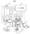
- An example of the control block of the engine control apparatus provided with the intake pipe pressure calculation method of the engine used as the object of the present invention An example of the engine periphery which the engine control apparatus provided with the intake pipe pressure calculation method of the engine used as the object of the present invention controls.
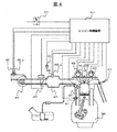
- the other example of the control block of the engine control apparatus provided with the intake pipe pressure calculation method of the engine used as the object of the present invention The other example of the engine periphery which the engine control apparatus provided with the intake-pipe pressure calculation method of the engine used as the object of this invention controls.
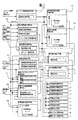
- FIG. 1 is an example of a block diagram of a block diagram of control of a basic portion of an engine control apparatus provided with an engine intake pipe pressure calculation method that is an object of the present invention.
- FIG. 3 of the block diagram of control of the basic part of the engine control apparatus provided with the intake pipe pressure calculation method of the engine which is the subject of the present invention.
- FIG. 8 is an example of a specific method for obtaining the throttle passage air flow rate in FIG. 7.
- This is a block diagram for calculating the theoretical formula of Formula 9 with a microcomputer.
- FIG. 1 is an example of a detailed flowchart of FIG. 1 of a control block of an engine control apparatus including an engine intake pipe pressure calculation method that is a subject of the present invention.
- FIG. 4 is an example of a detailed flowchart of FIG. 3 of a control block of an engine control apparatus including an engine intake pipe pressure calculation method that is an object of the present invention.
- FIG. 7 is an example of a detailed flowchart of FIG. 6 of a control block of an engine control device provided with an engine intake pipe pressure calculation method that is an object of the present invention.
- FIG. 8 is an example of a detailed flowchart of FIG.
- FIG. 7 showing a control block of an engine control apparatus including an engine intake pipe pressure calculation method that is an object of the present invention.
- FIG. 9 is an example of a detailed flowchart of FIG. 8 of a control block of an engine control device including an engine intake pipe pressure calculation method that is a subject of the present invention.
- FIG. 10 is an example of a detailed flowchart of FIG. 9 of a control block of an engine control device provided with an engine intake pipe pressure calculation method that is an object of the present invention.
- FIG. 1 is an example of a control block of an engine control apparatus including an engine intake pipe pressure calculation method that is a target of the present embodiment.
- the engine speed calculation means 101 counts the electric signal of the crank angle sensor set at a predetermined crank angle position of the engine, mainly the number of inputs per unit time of the change of the pulse signal, and performs arithmetic processing to thereby calculate the engine Calculate the number of revolutions per unit time.
- the intake air amount calculation means 102 calculates an intake pipe pressure calculation value based on the H / W sensor output, the intake air temperature sensor output, the humidity sensor output, the atmospheric pressure sensor output, and the aforementioned engine speed, and uses them to calculate the engine.
- the amount of air flowing into the cylinder is calculated.
- the basic fuel calculation means 103 calculates the basic fuel required by the engine and the engine load index in each region based on the engine speed calculated by the engine speed calculation means 101 and the amount of air flowing into the engine cylinder. To do.
- the basic fuel correction coefficient calculation means 104 calculates a correction coefficient for each operating region of the basic fuel calculated by the basic fuel calculation means 103 based on the engine speed calculated by the engine speed calculation means 101 and the engine load. To do.
- the basic ignition timing calculation means 105 determines the optimal ignition timing in each region of the engine by map search or the like based on the above engine speed and the above engine load.
- the acceleration / deceleration determination means 106 performs engine transient determination based on the throttle opening described above, and calculates acceleration / deceleration fuel correction and acceleration / deceleration display correction amount associated with the transient.
- the intake / exhaust valve timing setting means 107 is a block for determining the optimum intake and exhaust valve opening / closing timings for the engine based on the engine speed calculated by the engine speed calculation means 101 and the engine load.
- the air-fuel ratio feedback control coefficient calculation means 108 determines the air-fuel ratio so that the mixture of fuel and air supplied to the engine is maintained at a target air-fuel ratio described later from the output of the oxygen concentration sensor set in the exhaust pipe of the engine. Calculate the feedback control coefficient.
- the oxygen concentration sensor described above outputs a signal proportional to the exhaust air / fuel ratio, but the exhaust gas has a rich / lean side with respect to the stoichiometric air / fuel ratio. There is no problem even if it outputs two signals.
- the target air-fuel ratio setting means 109 determines the optimal target air-fuel ratio in each region of the engine by map search or the like based on the engine speed and the engine load described above.
- the target air-fuel ratio determined in this block is used for air-fuel ratio feedback control of the air-fuel ratio feedback control coefficient calculation means 108.
- the target air-fuel ratio setting means 109 uses the basic fuel calculated by the basic fuel calculation means 103 as the basic fuel correction coefficient of the basic fuel correction coefficient calculation means 104, the acceleration / deceleration fuel correction amount of the acceleration / deceleration determination means 106, and the air-fuel ratio feedback control. Correction by the air-fuel ratio feedback control coefficient of the coefficient calculation means 108 is performed.
- the ignition timing correction unit 111 corrects the ignition timing searched by the basic fuel correction coefficient calculation unit 104 with the acceleration / deceleration fuel correction amount of the acceleration / deceleration determination unit 106 described above.
- the cylinder fuel injection means 112 to 115 are fuel injection means for supplying the amount of fuel calculated by the basic fuel correction means 110 to the engine.
- the cylinder ignition means 116 to 119 are ignition means for igniting the fuel mixture flowing into the cylinder in accordance with the required ignition timing of the engine corrected by the ignition timing correction means 111.
- the intake valve control means 120 and the exhaust valve control means 121 control the opening / closing timing of the intake / exhaust valve calculated by the intake / exhaust valve timing setting means 107.
- FIG. 2 shows an example of the engine periphery controlled by the engine control device provided with the method for calculating the intake pipe pressure of the engine which is the object of the present embodiment.
- the H / W sensor 201 measures the amount of air passing through the throttle portion of the engine integrated with the humidity sensor 201_a that measures the humidity of the air passing through the throttle portion.
- a throttle throttle valve 202 provided in the intake passage of the engine limits the driver's opening adjustment by a motor.
- the atmospheric pressure sensor 203 measures the atmospheric pressure.
- the pressure sensor 205 measures the pressure in the intake pipe 204 integrated with the intake air temperature sensor 205_a that measures the temperature of the air in the intake pipe 204.
- the fuel injection valve 206 supplies the fuel required by the engine.
- the intake valve control device 207_a controls the intake timing of the engine air in which the crank angle sensor 207 set at a predetermined crank angle position of the engine is integrated.
- the exhaust valve control device 208 controls the timing of exhausting the engine exhaust gas.
- the ignition module 208 supplies ignition energy to an ignition plug that ignites a fuel mixture supplied into an engine cylinder based on an ignition signal from the engine control unit 214.
- the water temperature sensor 209 is set in the cylinder block of the engine and detects the cooling water temperature of the engine.
- the water temperature sensor 210 measures the temperature of the engine coolant temperature.
- the oxygen concentration sensor 211 is set in the exhaust pipe of the engine and detects the oxygen concentration in the exhaust gas.
- the three-way catalyst 212 is installed behind the oxygen concentration sensor in the exhaust pipe.
- the engine control device 214 controls an ignition key switch 213 which is a main switch for engine operation and stop, and each engine auxiliary device.
- the humidity sensor 201_a and the H / W sensor 201 are integrated, but there is no problem even if they are separate.
- the H / W sensor 201 may be a thermal air flow meter. Thereby, the mass flow rate of air can be measured without being influenced by the intake air temperature.
- the intake air temperature sensor 205_a and the pressure sensor 205, and the crank angle sensor 207 and the intake valve control device 207_a are integrated, but there is no problem even if they are separated.
- the humidity sensor 201_a is configured to measure the humidity of air passing through the throttle with the H / W sensor 201 integrated, but as described above, the humidity sensor 201_a separately measures the humidity of the air in the intake manifold. Also good.
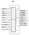
- FIG. 5 is an example of an internal configuration of an engine control device including an engine intake pipe pressure calculation method that is a target of the present embodiment.
- the CPU 501 has an I / O unit 502 for converting electrical signals of sensors installed in the engine into signals for digital arithmetic processing and converting control signals for digital arithmetic into actual actuator drive signals.
- the I / O unit 502 includes an intake air amount sensor 503, a humidity sensor 504, an intake pipe pressure sensor 505, an intake air temperature sensor 506, an atmospheric pressure sensor 507, a water temperature sensor 508, a crank angle sensor 509, a throttle opening sensor 510, oxygen A density sensor 511 and an ignition SW 512 are input.
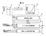
- FIG. 6 is an example of FIG. 1 of a block diagram of control of a basic portion of an engine control apparatus provided with an engine intake pipe pressure calculation method that is a target of the present embodiment.
- the CPU 501 of the engine control device shown in FIG. 5 controls the engine shown in FIG. 2 by each functional block shown in FIG.
- the output voltage corresponding to the flow rate of the H / W sensor 601 is filtered by the hard filter 602 and further filtered by the filtering 603.
- the filtered output voltage value of the air flow rate is converted into an air flow rate corresponding to the voltage by a table search in block 604.
- the CPU 501 of the engine control device includes an air amount calculation unit (block 604) that calculates the amount of air flowing into the engine cylinder based on the measurement result of the H / W sensor 601 (air amount measurement unit).
- a block 605 is a basic block of the present embodiment, and corrects the gas constant by humidity using the intake air temperature THA, the humidity sensor output RH, and the atmospheric pressure Patm input to the block.
- the CPU 501 of the engine control device corrects the gas constant according to Equation 9 described later using the intake air temperature THA, the atmospheric humidity (humidity sensor output RH) measured by the humidity measuring unit (humidity sensor 201_a), and the atmospheric pressure Patm.
- a gas constant correction unit (block 605).
- Block 606 calculates the pressure in the intake pipe using the gas constant corrected in block 605.
- Block 607 calculates the amount of air flowing into the cylinder based on the calculated pressure, intake air temperature, and engine speed.
- the CPU 501 of the engine control device includes an air amount measured by the H / W sensor 601 (air amount measuring unit), an air amount calculated by the air amount calculating unit (block 604), and a humidity measuring unit (humidity sensor).
- 201_a has a pressure calculation unit (block 606) that calculates the pressure of the intake manifold based on the atmospheric humidity measured by 201_a).
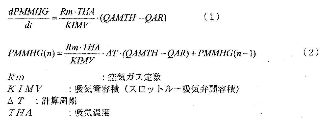
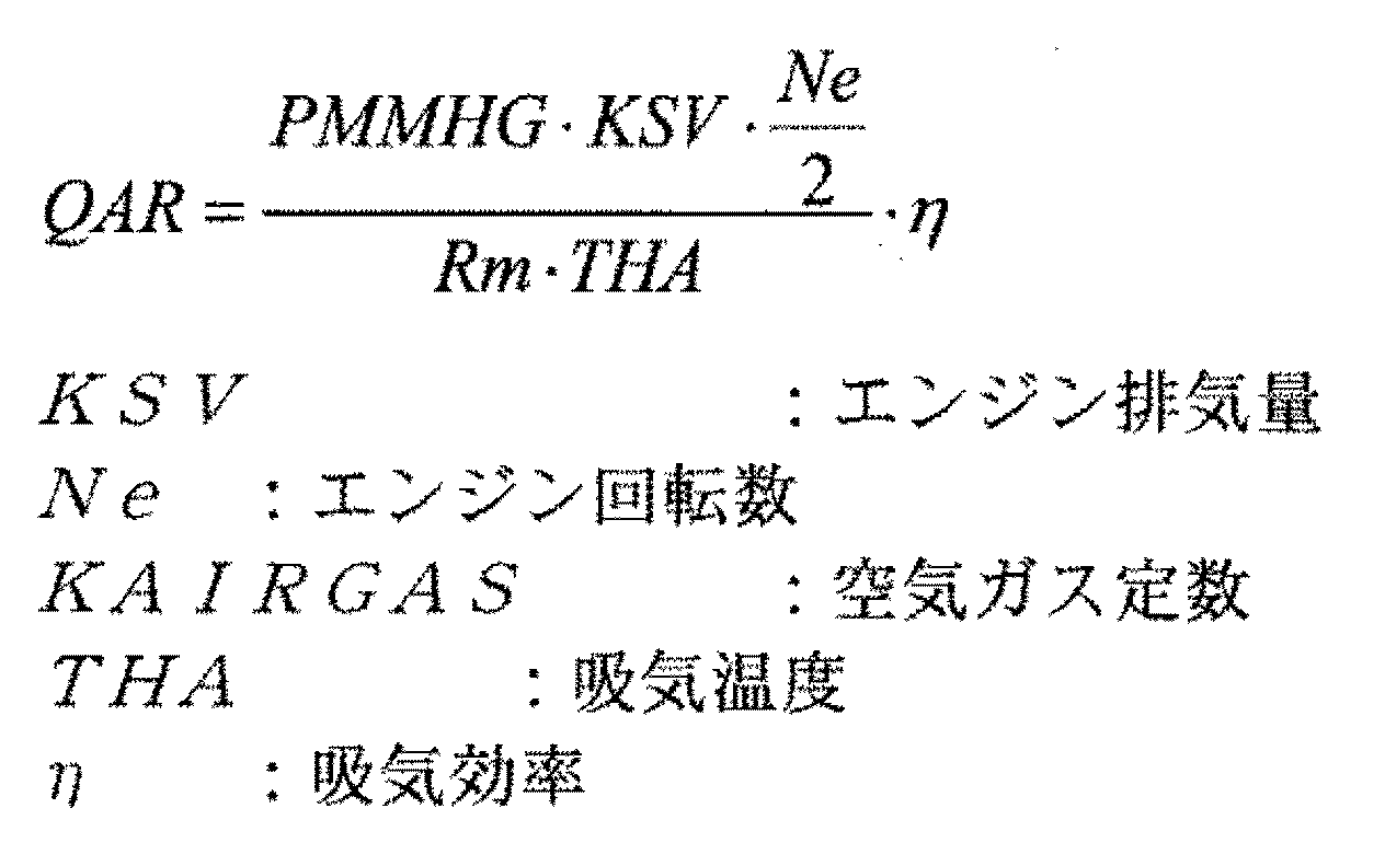
- the gas constants corrected to the amount of air entering the intake pipe (H / W sensor lightweight air amount QA00) and the amount of air exiting from the intake pipe (cylinder inflow air amount QAR) of equation (1) are included.
- the product of the theoretical coefficient is obtained as the pressure change in the intake pipe. Note that because of the microcomputer calculation, the continuous value is actually calculated as the calculation period ⁇ T as shown in (2) of equation 1 by applying Z conversion to (1) of equation 1.
- the expression (3) in Expression 1 is calculated to obtain the cylinder inflow air amount.
- the gas constant correction unit (block 605) corrects the gas constant using the humidity sensor output RH according to Equation 9, and the pressure calculation unit (block 606) uses the corrected gas constant.
- the pressure of the intake manifold can be calculated with higher accuracy.
- FIG. 3 shows another example of the control block of the engine control apparatus provided with the method for calculating the intake pipe pressure of the engine which is the subject of this embodiment.
- the engine speed calculation means 301 counts the electrical signal of the crank angle sensor set at a predetermined crank angle position of the engine, mainly the number of inputs per unit time of the pulse signal change, and performs arithmetic processing to thereby calculate the engine Calculate the number of revolutions per unit time.
- the intake air amount calculation means 302 is an H / W sensor output, an intake temperature sensor output, a throttle sensor output, a humidity sensor output, and an atmospheric pressure sensor, and a turbine-throttle pressure calculation value, a throttle air amount, an intake pipe pressure calculation value And the amount of air flowing into the engine cylinder is calculated using them.
- the basic fuel calculation means 303 calculates the basic fuel and engine load index required by the engine in each region based on the engine speed calculated by the engine speed calculation means 301 and the amount of air flowing into the engine cylinder. To do.
- the basic fuel correction coefficient calculation means 304 is a correction coefficient for each operating region of the basic fuel calculated by the basic fuel calculation means 303 based on the engine speed calculated by the engine speed calculation means 301 and the engine load described above.
- Calculate The basic ignition timing calculation means 305 determines the optimal ignition timing in each region of the engine by map search or the like based on the above engine speed and the above engine load.
- the acceleration / deceleration determining means 306 performs engine transient determination based on the throttle opening described above, and calculates acceleration / deceleration fuel correction and acceleration / deceleration display correction amount associated with the transient.
- the intake / exhaust valve timing setting means 307 determines the intake / exhaust valve opening / closing timing optimum for the engine based on the engine speed and the engine load.
- the air-fuel ratio feedback control coefficient calculation means 308 is configured to adjust the air-fuel ratio so that the mixture of fuel and air supplied to the engine is maintained at a target air-fuel ratio described later from the output of the oxygen concentration sensor set in the exhaust pipe of the engine. Calculate the feedback control coefficient.
- the oxygen concentration sensor described above outputs a signal proportional to the exhaust air / fuel ratio.
- the exhaust gas has a rich side / lean side 2 with respect to the stoichiometric air / fuel ratio. There is no problem even if it outputs two signals.
- the target air-fuel ratio setting means 309 determines an optimal target air-fuel ratio in each region of the engine by map search or the like based on the engine speed and the engine load described above.
- the target air-fuel ratio determined in this block is used for air-fuel ratio feedback control of the air-fuel ratio feedback control coefficient calculation means 308.
- the basic fuel correction means 310 uses the basic fuel calculated by the basic fuel calculation means 303 as the basic fuel correction coefficient of the basic fuel correction coefficient calculation means 304, the acceleration / deceleration fuel correction amount of the acceleration / deceleration determination means 306, and the air-fuel ratio feedback control coefficient. Correction by the air-fuel ratio feedback control coefficient of the calculation means 308 is performed.
- the ignition timing correction unit 311 corrects the ignition timing searched by the basic fuel correction coefficient calculation unit 304 with the acceleration / deceleration fuel correction amount of the acceleration / deceleration determination unit 306.
- the cylinder fuel injection means 312 to 315 supply the fuel amount calculated by the basic fuel correction means 310 to the engine.
- the cylinder ignition means 316 to 319 ignite the fuel mixture flowing into the cylinder in accordance with the required ignition timing of the engine corrected by the ignition timing correction means 311.
- the intake valve control means 320 and the intake valve control means 321 control the opening / closing timing of the intake / exhaust valve calculated by the intake / exhaust valve timing setting means 307.
- FIG. 4 shows another example of the engine periphery controlled by the engine control device equipped with the method for calculating the intake pipe pressure of the engine which is the subject of the present embodiment.
- the engine 400 is equipped with an H / W sensor 401 that measures the amount of air that passes through the throttle portion of the engine integrated with a humidity sensor 401_a that measures the humidity of the air that passes through the throttle portion. Further, the engine 400 includes a supercharger 402 that is set downstream of the H / W sensor 401 and pressurizes the amount of air to be sucked in conjunction with the turbine on the exhaust side.
- the engine 400 includes a fuel injection valve 407 that supplies fuel required by the engine, and a crank angle sensor 408 that is set at a predetermined crank angle position of the engine.
- An ignition module 409 that supplies ignition energy based on the ignition signal of the engine control device 414 is attached to the valve control device 408_a and an ignition plug that ignites the fuel mixture supplied into the cylinder of the engine.
- an exhaust valve control device 410 that controls the timing of exhausting the exhaust gas of the engine, a water temperature sensor 411 that is set in the cylinder block of the engine and detects the cooling water temperature of the engine, and an oxygen concentration in the exhaust gas that is set in the exhaust pipe of the engine
- An oxygen concentration sensor 412 to be detected, an ignition key switch 413 that is a main switch for operating and stopping the engine, an engine control device 414 for controlling each engine accessory, and the like are attached to the engine 400.
- the humidity sensor 401_a and the H / W sensor 401 are integrated, but there is no problem even if they are separate.
- the intake air temperature sensor 406_a and the pressure sensor 406, and the crank angle sensor 208 and the intake valve control device 408_a are integrated, but there is no problem even if they are separated.
- the humidity sensor 401_a is integrated with the H / W sensor 401 to measure the humidity of the air passing through the throttle. As described above, the air between the turbine and the throttle or in the intake manifold is separately provided. You may measure the humidity.
- FIG. 7 is an example of a block diagram of FIG. 3 showing a control of a basic part of an engine control device provided with an engine intake pipe pressure calculation method which is a target of the present embodiment.
- the CPU 501 of the engine control device shown in FIG. 5 controls the engine shown in FIG. 4 by each functional block shown in FIG.
- a block 701 is a block that corrects the gas constant due to humidity using the intake air temperature THA, the humidity sensor output RH, and the atmospheric pressure Patm. That is, the CPU 501 of the engine control device corrects the gas constant according to Equation 9 described later using the intake air temperature THA, the atmospheric humidity (humidity sensor output RH) measured by the humidity measuring unit (humidity sensor 401_a), and the atmospheric pressure Patm.
- Block 702 is a block for calculating the turbine-throttle pressure PMTRTH.
- the current PMTRTH is calculated using the corrected gas constant Rm, the intake air amount QA00, the intake air temperature THA, the previously calculated throttle passage air amount QAMTH, and the previously calculated PMTRTH. Therefore, the pressure calculation unit (block 702) of the CPU 501 of the engine control device passes the air amount measured by the H / W sensor 401 (air amount measurement unit) and the throttle throttle valve 403 on the downstream side of the supercharger 402.
- the turbine-throttle pressure PMTRTH is calculated based on the air amount calculated by the throttle passage air amount calculation unit (block 703) for calculating the air amount to be measured and the atmospheric humidity measured by the humidity measurement unit (humidity sensor 401_a). It has a pressure calculation part (block 702) to calculate.
- Block 703 is a block for calculating the throttle passage air amount QAMTH.
- QAMTH is calculated using the corrected gas constant Rm, throttle opening area AA, intake air temperature, the turbine-throttle pressure PMTRTH, and the previously calculated intake pipe pressure PMMHG. That is, the CPU 501 of the engine control device has a throttle passage air amount calculation unit (block 703) that calculates the throttle passage air amount QAMTH based on the atmospheric humidity measured by the humidity measurement unit (humidity sensor 401_a).
- Block 704 is a block for calculating the intake pipe pressure PMMHG.
- the current PMMHG is calculated using the corrected gas constant Rm, the intake air temperature THA, the throttle passing air amount QAMTH, the previously calculated cylinder inflow air amount QAR, and the previously calculated PMMHG.
- the CPU 501 of the engine control device uses the throttle passage air amount QAMTH passing through the throttle throttle valve 403 calculated by the throttle passage air amount calculation unit (block 703) and the supercharger calculated by the pressure calculation unit (block 702). Based on the turbine-throttle pressure PMTRTH between 402 and the throttle throttle valve 403 on the downstream side of the supercharger 402, and the humidity measured by the humidity measuring unit (humidity sensor 401_a), downstream of the throttle throttle valve 403.
- An intake pipe pressure calculation unit (block 704) for calculating the intake pipe pressure PMMHG of the intake manifold 405 on the side.
- Block 705 obtains an intake efficiency ⁇ , which is a non-linear element, from a map search based on the engine speed Ne and the intake pipe pressure PMMHG. ⁇ corrects a deviation from the theoretical value of the cylinder inflow air amount obtained based on the intake pipe pressure.
- a block 706 is a block for obtaining the cylinder inflow air amount QAR. QAR is calculated using the corrected gas constant Rm, the engine speed Ne, the intake air temperature THA, the intake pipe pressure PMMHG, and the intake efficiency ⁇ . That is, the CPU 501 of the engine control device determines the amount of air passing through the throttle throttle valve 403 calculated by the throttle passage air amount calculation unit (block 703), the supercharger calculated by the pressure calculation unit, and the supercharging.
- Cylinder inflow air amount calculation unit for calculating the cylinder inflow air amount QAR based on the pressure between the throttle throttle valve on the downstream side of the vessel and the atmospheric humidity measured by the humidity measurement unit (humidity sensor 401_a) 705).
- the turbine-throttle pressure is calculated from the intake air amount or the like.
- the output value may be used.
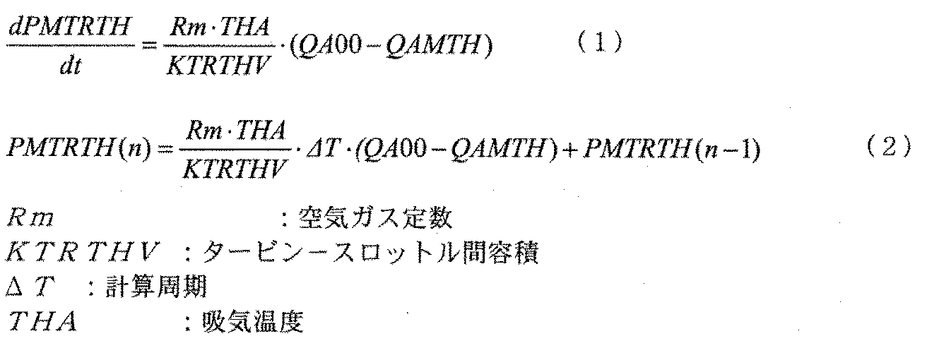
- Formula 2 shows the theoretical formula for obtaining the turbine-throttle pressure in FIG. Equation (1) shows a theoretical formula in the continuous region, and shows that the inflow / outflow of air in a very short time between the turbine and the throttle becomes a pressure gradient between the turbine and the throttle.
- Equation (2) is a discretization of Equation (1), and the pressure calculation unit (block 702) obtains the turbine-throttle pressure PMTRTH by executing this equation. Yes.
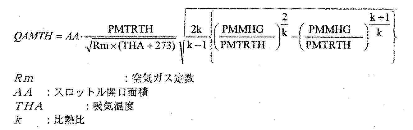
- Formula 3 shows a theoretical formula for obtaining the throttle passage air amount QAMTH in FIG. 5 described above, and the throttle passage air amount calculation unit (block 703) calculates the throttle passage air amount QAMTH using this equation.
- Formula 4 shows a theoretical formula for obtaining the intake pipe pressure PMMHG of FIG. Similar to Equation 2 above, Equation (1) in Equation 4 shows a theoretical equation in the continuous region, and shows that inflow / outflow of air into the intake pipe in a very short time becomes a pressure gradient in the intake pipe. Yes.
- Expression (2) is obtained by discretizing Expression (1), and the intake pipe pressure calculation unit (block 704) obtains the intake pipe pressure PMMHG by executing this expression.
- Expression 5 shows a theoretical expression for obtaining the cylinder inflow air amount QAR in FIG. 7 described above, and the cylinder inflow air amount calculation unit (block 705) calculates the cylinder inflow air amount QAR using this expression.
- FIG. 8 is an example of a specific method for obtaining the throttle passage air flow rate shown in FIG.
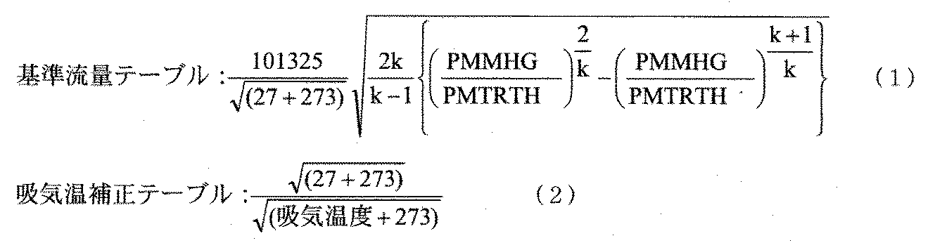
- a table of the inflow air amount at the reference opening area based on the ratio of the intake pipe pressure PMMHG at the constant intake air temperature and the turbine-throttle pressure is set, and the reference flow rate is output. Specifically, the calculated value of Equation 6 (1) is set.
- the above-described intake air temperature correction values for the reference flow rate are tabulated, and specifically, the calculated value of Equation 6 (2) is set.
- the multiplier 804 calculates the throttle passage air flow rate QAMTH by throttle opening area AA ⁇ turbine-throttle pressure PMTRTH / 101325 ⁇ reference flow rate ⁇ intake air temperature correction value ⁇ 1 / ⁇ gas constant Rm.
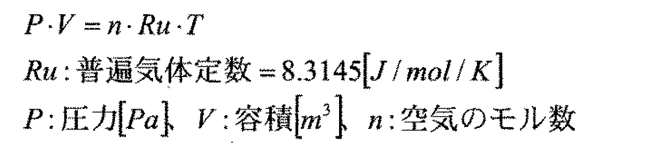
- Equation 7 shows the equation of state of the ideal gas in the intake pipe.
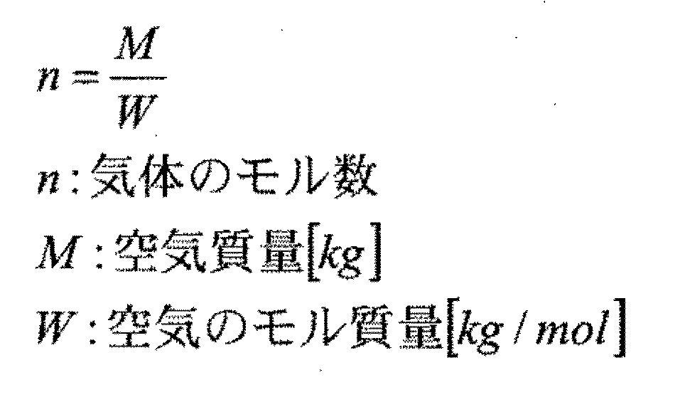
- Ru indicates a universal gas constant, where n is the number of moles of air.
- Equation 8 shows that the number of moles of gas is the mass of air divided by the molar mass of air.
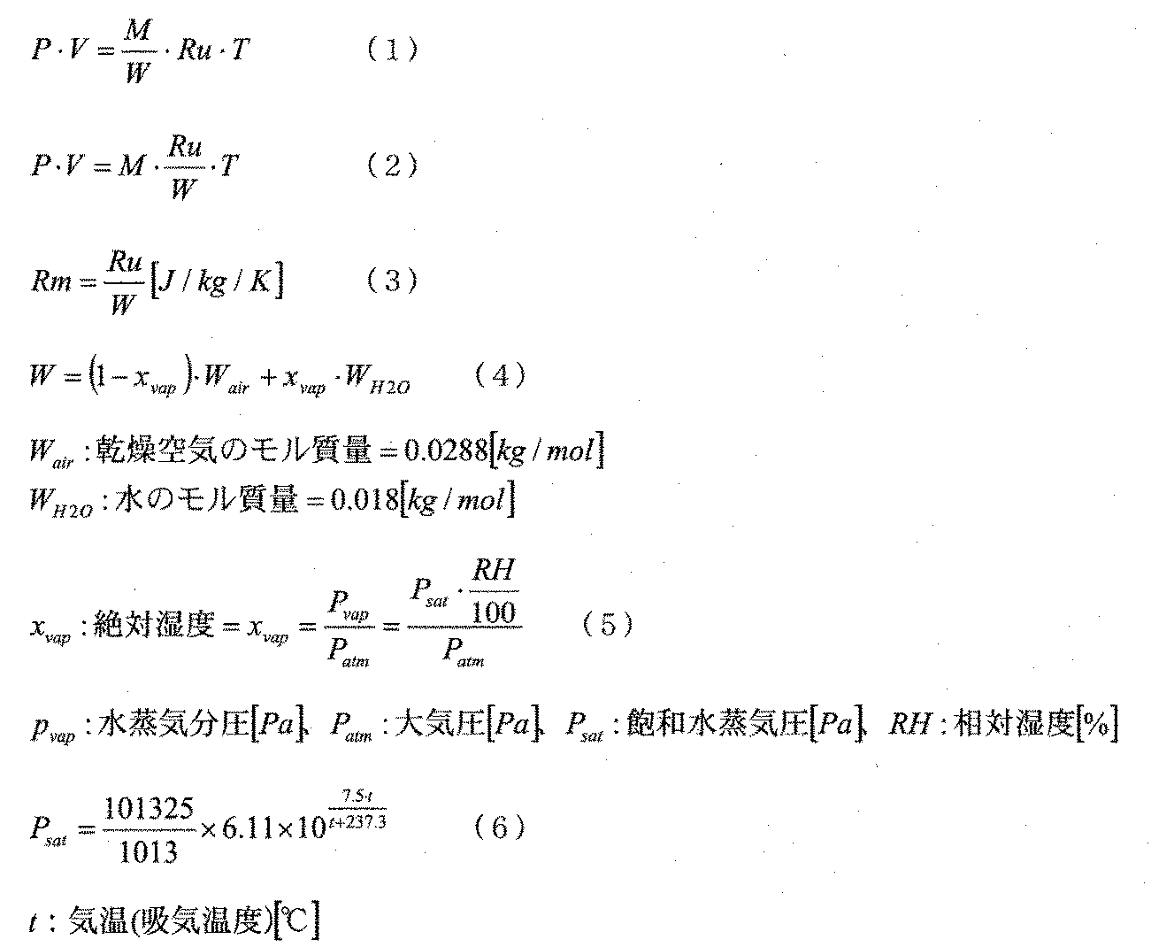
- Equation 9 (1) is obtained by substituting Equation 8 into Equation 7, which can be transformed as Equation 9 (2).
- the gas constant dealt with in this example is expressed by the equation 9 (3), which is a value obtained by dividing the above-mentioned universal gas constant Ru by the total number of moles W of air, and the total number of moles W of air is It is calculated
- Equation 9 (4) shows, the gas constant is affected by absolute humidity.
- the absolute humidity xvap is expressed by Equation 9 (5), which is a value obtained by dividing the water vapor pressure Pvap of water by the atmospheric pressure Patm.
- the water vapor pressure Pvap of water is a value obtained by dividing the saturated water vapor pressure Psat by the relative humidity RH by 100. It is calculated by multiplying.
- Expression 9 (6) represents an approximate expression of the relationship between the saturated water vapor pressure Psat and the air temperature (intake air temperature) t. When realized by a microcomputer, this expression may be calculated, but the air temperature (intake air temperature) You may implement
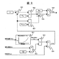
- FIG. 9 shows a block diagram for calculating the theoretical formula of Formula 9 by a microcomputer.
- the table is searched for the saturated water vapor pressure Psat with the intake air temperature THA.
- the relative humidity RH is divided by 100, and in block 903, the aforementioned saturated water vapor pressure Psat is multiplied.
- the multiplied value is divided by the atmospheric pressure in block 904, and the absolute humidity xvap is output.
- the absolute humidity xvap is subtracted from 1; in block 906, the molar mass of dry air is multiplied; in block 907, the absolute humidity xvap is multiplied by the molar mass of water;
- the number of moles W is output.
- the gas constant Rm corrected for humidity is output by dividing the universal gas constant by the total number of moles W of the air.
- FIG. 10 is an example of the output of the calculated pressure of the engine control device provided with the method for calculating the intake pipe pressure of the engine which is the subject of this embodiment.
- a line 1001 represents the relative humidity and changes from the timing 1002.
- the intake pipe calculated pressure remains constant as shown by line 1003 when there is no main humidity correction, but changes as shown by line 1004 when there is correction.
- the pressure calculating unit (block 606, block 702) calculates the pressure of the intake manifold (204, 405) so as to increase as the humidity measured by the humidity measuring unit (humidity sensor 201_a, humidity sensor 401_a) increases.
- FIG. 11 shows an example in which an exhaust gas recirculation device of an engine control device provided with a method for calculating an intake pipe pressure of an engine which is a target of the present embodiment is provided.
- An H / W sensor 1101 that measures the amount of air that passes through the throttle portion of the engine in which a humidity sensor that measures the humidity of air that passes through the throttle portion is integrated with the engine 1100, and the temperature of the air inside the intake passage is measured.
- a pressure sensor 1103 for measuring the pressure inside the intake pipe 1102 integrated with the intake air temperature sensor a passage 1105 connecting the exhaust pipe 1104 and the intake pipe 1102 of the engine, and a passage 1105 connecting the exhaust pipe 1104 and the intake pipe 1102.
- the EGR valve 1106 that adjusts the flow rate of the exhaust gas that is set and flows through the passage 1105 and the EGR gas temperature sensor 1107 that measures the exhaust gas temperature in the passage 1105 are configured.
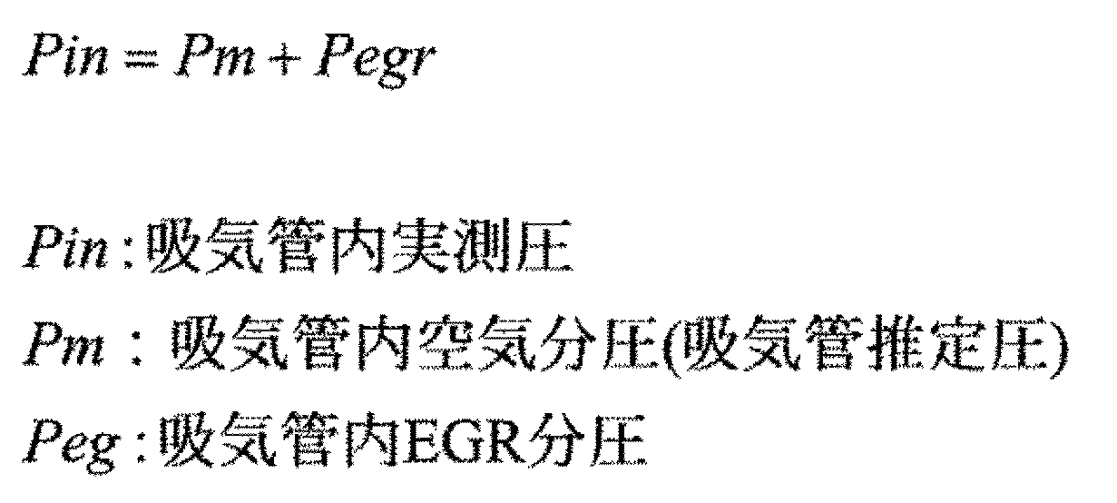
- Equation 10 represents the relationship of the pressure in the intake pipe.
- the actually measured pressure in the intake pipe is a value obtained by adding the partial pressure of air in the intake pipe, that is, the above-described calculated pressure in the intake pipe and the EGR partial pressure in the intake pipe.
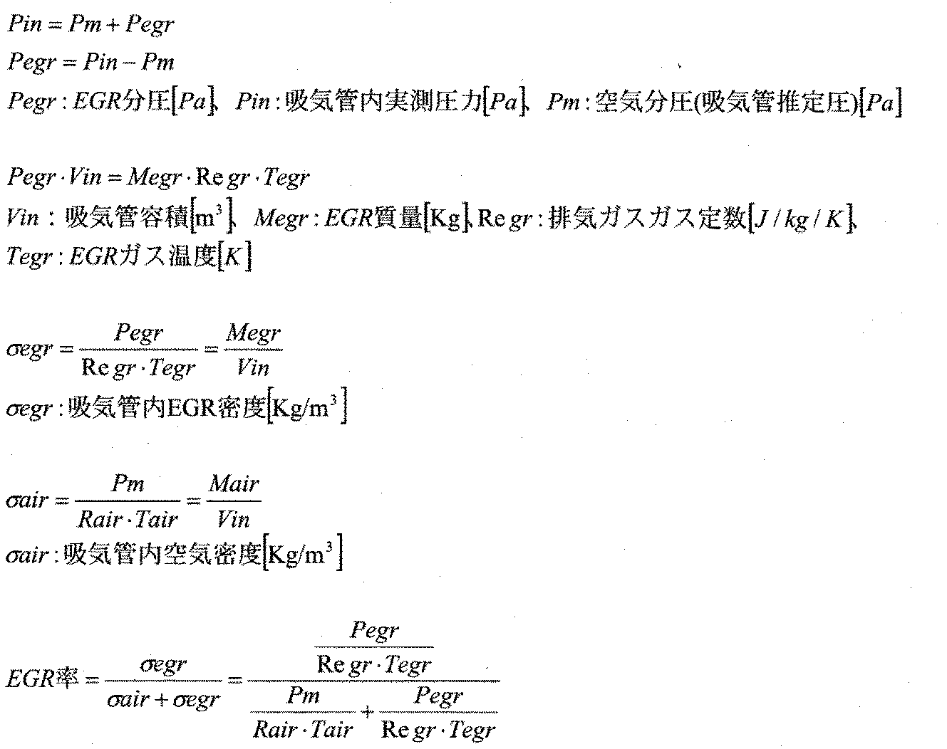
- Equation 11 (1) is the relationship of Equation 10, and can be transformed as Equation 11 (2).
- the EGR partial pressure in the intake pipe is a value obtained by subtracting the air partial pressure (calculated pressure in the intake pipe) from the actually measured pressure in the intake pipe.
- Expression 11 (3) is a modification of the state equation of EGR gas in the intake pipe and represents the EGR gas density in the intake pipe.
- Expression 11 (4) is a modification of the equation of state of air in the intake pipe, and represents the air density in the intake pipe.
- Pm is the above-mentioned calculated intake pipe pressure.
- Expression 11 (5) is an expression for the EGR rate, and indicates that the EGR rate is obtained by a value obtained by adding the EGR gas density in the intake pipe to the EGR gas density in the intake pipe and the air density in the intake pipe.
- the pressure calculation unit calculates the pressure of the intake manifold (intake pipe 1102) from the humidity measured by the humidity measurement unit (humidity sensor 1101) by the method described above. Then, the CPU 501 of the engine control device controls the opening degree of the EGR valve 1106 so that the difference between the detection value of the pressure sensor 1103 and the pressure calculated by the pressure calculation unit (block 606) becomes a set value. Part. When the humidity measured by the humidity measuring unit (humidity sensor 1101) changes, the EGR valve control unit opens the opening of the EGR valve 1106 (throttle valve) so as to change the exhaust gas recirculation amount in the passage connecting the exhaust pipe and the intake pipe. To control.
- the intake pipe estimated pressure increases. Since the EGR rate decreases as Pm increases from the last equation of Equation 11, the EGR valve control unit increases the opening of the EGR valve 1106 (throttle valve) to achieve the target EGR rate when the humidity increases. To control.
- the above set value is set so that the engine surge becomes equal to or less than the predetermined value while the NOx emission amount becomes equal to or less than the predetermined value. That is, the set value is set to a value that can achieve both emissions such as NOx and drivability in the operation region.
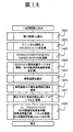
- FIG. 12 is an example of a detailed flowchart of FIG. 1 of the control block of the engine control device provided with the engine intake pipe pressure calculation method that is the subject of this embodiment.
- the engine speed is calculated.
- outputs of the H / W sensor, the intake air temperature sensor, the humidity sensor, and the atmospheric pressure sensor are read.
- the gas constant due to humidity is corrected.
- the intake pipe pressure is calculated.
- the amount of cylinder inflow air flowing into the engine cylinder is calculated from the calculated value of the intake pipe pressure.
- the basic fuel of the engine and the engine load are calculated from the aforementioned engine speed and cylinder inflow air amount.
- the basic fuel correction coefficient of the engine is retrieved from the map based on the engine speed and the engine load.
- acceleration / deceleration determination based on the throttle sensor output is performed.
- a fuel correction amount at the time of acceleration / deceleration determination is calculated.
- the oxygen concentration sensor output is read.
- a target air-fuel ratio suitable for each operating region of the engine is set.
- air-fuel ratio feedback control is performed using the aforementioned oxygen concentration sensor output and the aforementioned target air-fuel ratio, and an air-fuel ratio feedback control coefficient is calculated.
- the basic fuel is corrected using the basic fuel correction coefficient, the fuel correction amount at the time of acceleration / deceleration determination, and the air-fuel ratio feedback control coefficient.
- a map search is made for the basic ignition timing based on the engine speed and the engine load.
- an acceleration / deceleration ignition timing correction amount for the basic ignition timing is calculated during acceleration.
- acceleration / deceleration ignition timing correction is applied to the basic ignition timing.
- the intake / exhaust valve timing suitable for each operation region of the engine is set.
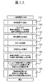
- FIG. 13 is an example of a detailed flowchart of FIG. 3 of the control block of the engine control apparatus provided with the engine intake pipe pressure calculation method that is the subject of this embodiment.
- the engine speed is calculated.
- the H / W sensor, intake air temperature sensor, humidity sensor, throttle sensor, and atmospheric pressure sensor output are read.
- the turbine-throttle calculated pressure and the intake pipe calculated pressure are initialized by the atmospheric pressure sensor output.
- the gas constant due to humidity is corrected.
- a calculated turbine-throttle pressure is calculated.
- the throttle opening area is calculated from the throttle sensor.
- the air flow rate through the throttle is calculated.
- the calculated intake pipe pressure value is calculated.
- the cylinder inflow air amount is calculated from the engine speed and the intake pipe pressure calculation value.
- the basic fuel and engine load of the engine are calculated based on the engine speed and the cylinder inflow air amount.
- the basic fuel correction coefficient is searched for a map with the aforementioned engine speed and the aforementioned engine load.
- acceleration / deceleration is determined by the throttle sensor output.
- the acceleration / deceleration fuel correction amount is calculated from the acceleration / deceleration determination value described above.
- the oxygen concentration sensor output is read.
- a map search is performed for the target air-fuel ratio suitable for each operating region of the engine based on the aforementioned engine speed and engine load.
- an air-fuel ratio feedback control coefficient is calculated from the target air-fuel ratio and the oxygen concentration sensor output.
- the basic fuel amount is corrected using the basic fuel correction coefficient, the acceleration / deceleration fuel correction amount, and the air-fuel ratio feedback control coefficient.
- the map is searched for the basic ignition timing suitable for each operating region of the engine based on the engine speed and the engine load.
- the acceleration / deceleration ignition timing correction amount is calculated by the aforementioned acceleration / deceleration determination.
- the basic ignition timing is corrected.
- the intake / exhaust valve timing suitable for each engine operating region is set.
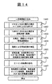
- FIG. 14 is an example of a detailed flowchart of FIG. 6 of the control block of the engine control apparatus provided with the engine intake pipe pressure calculation method that is the subject of this embodiment.
- the output voltage of the H / W sensor is taken in and filtered by a hard filter.
- the filtered voltage is converted to an air flow rate.
- the outputs of the atmospheric pressure sensor, the humidity sensor, and the intake air temperature sensor are read.
- the gas constant due to humidity is corrected.
- the intake pipe pressure calculation value is calculated using the above-described air flow rate, the previously calculated cylinder inflow air amount, and the above-described corrected gas constant.
- the engine speed is read.
- the cylinder inflow air amount is calculated based on the calculated intake pipe pressure, the intake temperature, the engine speed, and the corrected gas constant.
- FIG. 15 is an example of a detailed flowchart of FIG. 7 of the control block of the engine control apparatus provided with the engine intake pipe pressure calculation method that is the subject of this embodiment.
- the outputs of the intake air temperature sensor, the humidity sensor, and the atmospheric pressure sensor are read.
- the gas constant due to humidity is corrected.
- the H / W sensor output value, the previous value of the air flow through the throttle, the previous value of the turbine-throttle pressure, and the corrected gas constant are read.
- the current turbine-throttle pressure is calculated. .
- the throttle opening area is read.
- the amount of air passing through the throttle is calculated based on the aforementioned throttle opening area, the aforementioned intake air temperature, the aforementioned current turbine-throttle pressure, the aforementioned corrected gas constant, and the previous value of the intake pipe pressure.
- the current intake pipe pressure calculation value is calculated based on the intake air temperature, the throttle passage air amount, the corrected gas constant, the previous value of the cylinder inflow air amount, and the previous intake pipe pressure calculation value.
- the map is searched for the intake efficiency based on the engine speed and the calculated intake pipe pressure.
- the cylinder inflow air amount is calculated based on the engine speed, the intake air temperature, the intake pipe pressure calculation value, the corrected gas constant, and the intake efficiency.
- FIG. 16 is an example of a detailed flowchart of FIG. 8 of the control block of the engine control apparatus provided with the engine intake pipe pressure calculation method that is the subject of this embodiment.
- the opening area AA is read.
- Block 1602 Turbine-throttle pressure PMTRTH is divided by 101325.
- the pressure ratio PMMHG / PMTRTH between the intake-air calculated pressure PMMHG and the turbine-throttle pressure PMTRTH is calculated.
- a reference flow rate table is retrieved from the above-mentioned pressure ratio, and a throttle passage air amount basic value is calculated.
- the intake air temperature is read.
- a table search is performed for the intake air temperature correction value from the above-described intake air temperature.
- the corrected gas constant Rm is converted into 1 / ⁇ Rm using a table.
- the throttle opening air amount QAMTH is calculated by multiplying the aforementioned opening area AA, the aforementioned PMTRTH / 101325, the aforementioned throttle passing air amount basic value, the aforementioned intake air temperature correction value, and the aforementioned 1 / ⁇ Rm.
- the throttle passage air amount QAMTH is calculated by combining the table search as described above, but it goes without saying that Equation 3 may be calculated as it is.
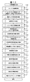
- FIG. 17 is an example of a detailed flowchart of FIG. 9 of the control block of the engine control apparatus provided with the engine intake pipe pressure calculation method that is the subject of this embodiment.
- the intake air temperature THA is read.
- the saturated water vapor pressure table is searched with the intake air temperature THA, and the saturated water vapor pressure Psat is calculated.
- the relative humidity RH is read.
- the relative humidity RH / 100 is calculated.
- the atmospheric pressure Patm is read.
- the aforementioned saturated water vapor pressure Psat ⁇ the aforementioned RH / 100 / the aforementioned atmospheric pressure Patm is calculated, and the absolute humidity xvap is calculated.
- the gas constant is corrected with respect to the humidity, so that a more accurate calculated pressure of the intake pipe can be calculated.
- the accuracy of calculating the EGR rate using the calculated pressure of the intake pipe can be increased.
Landscapes
- Engineering & Computer Science (AREA)
- Chemical & Material Sciences (AREA)
- Combustion & Propulsion (AREA)
- Mechanical Engineering (AREA)
- General Engineering & Computer Science (AREA)
- Physics & Mathematics (AREA)
- Fluid Mechanics (AREA)
- General Physics & Mathematics (AREA)
- Automation & Control Theory (AREA)
- Combined Controls Of Internal Combustion Engines (AREA)
- Electrical Control Of Air Or Fuel Supplied To Internal-Combustion Engine (AREA)
- Measuring Volume Flow (AREA)
- Measuring Fluid Pressure (AREA)
- Exhaust-Gas Circulating Devices (AREA)
- Output Control And Ontrol Of Special Type Engine (AREA)
Abstract
Description
図6は、本実施例の対象となるエンジンの吸気管圧力算出方法を備えたエンジン制御装置の基本部分の制御のブロック図の図1の例である。具体的には、図5で示したエンジン制御装置のCPU501は、図6で示すそれぞれの機能ブロックにより図2で示したエンジンの制御を行う。H/Wセンサ601の流量に応じた出力電圧は、ハードフィルタ602でフィルタリングを施され、さらにフィルタリング603でソフトフィルタを施される。フィルタリングを施された空気流量の出力電圧値は、ブロック604で、その電圧に応じた空気流量にテーブル検索にて変換される。エンジン制御装置のCPU501はH/Wセンサ601(空気量計測部)の計測結果に基づいてエンジンのシリンダへ流入する空気量を算出する空気量算出部(ブロック604)を有する。
ブロック605は、本実施例の基本部分のブロックであり、本ブロックに入力された吸気温度THA、湿度センサ出力RH、大気圧Patmを用いて湿度による気体定数の補正を行っている。つまり、エンジン制御装置のCPU501は吸気温度THAと湿度計測部(湿度センサ201_a)により計測された大気の湿度(湿度センサ出力RH)と大気圧Patmを用いて後述する式9に従って、気体定数を補正する気体定数補正部(ブロック605)を有する。
ブロック606はブロック605で補正された気体定数を使って吸気管内の圧力を算出するものであり、ブロック607は前記算出された圧力、吸気温度、及びエンジン回転数によりシリンダへ流入する空気量を計算するものである。つまり、エンジン制御装置のCPU501は、H/Wセンサ601(空気量計測部)により計測された空気量と、空気量算出部(ブロック604)により算出された空気量と、湿度計測部(湿度センサ201_a)により計測された大気の湿度とに基づいて、インテークマニフォールドの圧力を算出する圧力算出部(ブロック606)を有する。
ブロック606内部では、式1の(1)の吸気管に入る空気量(H/Wセンサ軽量空気量QA00)と吸気管から出る空気量(シリンダ流入空気量QAR)に補正された気体定数を含む理論係数を乗じたものを吸気管内の圧力変化分として求めている。尚、マイコン演算故、連続値に対しては式1の(2)に示すように計算周期ΔTとして、式1の(1)にZ変換を施したもので実際は演算している。ブロック607では、式1の(3)の式を演算してシリンダ流入空気量を求めている。

200 エンジン
201 H/Wセンサ
201_a 湿度センサ
202 スロットル絞り弁
203 大気圧センサ
204 吸気管
205 圧力センサ
205_a 吸気温センサ
206 燃料噴射弁
214 エンジン制御装置
302 吸入空気量計算手段
400 エンジン
401 H/Wセンサ
401_a 湿度センサ
402 過給器
403 スロットル絞り弁
404 大気圧センサ
405 吸気管
406 圧力センサ
406_a 吸気温センサ
407 燃料噴射弁
414 エンジン制御装置
501 CPU
502 I/O
503 吸入空気量センサ
504 湿度センサ
505 吸気管圧力センサ
506 吸気温度センサ
513 出力信号ドライバ
605 湿度による気体定数の補正ブロック
606 吸気管圧力算出ブロック
607 シリンダ流入空気量演算ブロック
701 湿度による気体定数の補正ブロック
702 タービン-スロットル間圧力算出ブロック
703 スロットル通過空気量計算ブロック
704 吸気管圧力算出ブロック
705 吸気効率演算ブロック
706 シリンダ流入空気量演算ブロック
1100 エンジン
1101 湿度センサ一体H/Wセンサ
1102 吸気管
1103 吸気温センサ一体圧力センサ
1104 排気管
1105 EGR配管
1106 EGRバルブ
1107 EGRガス温センサ
Claims (14)
- エンジンの吸気通路に設けられたスロットル絞り弁を通過する空気量を計測する空気量計測部と、前記スロットル絞り弁を通過する空気の湿度を計測する湿度計測部と、が取り付けられた前記エンジンを制御する制御装置において、
前記空気量計測部の計測結果に基づいて前記エンジンのシリンダへ流入する空気量を算出する空気量算出部と、
前記空気量計測部により計測された空気量と、前記空気量算出部により算出された空気量と、前記湿度計測部により計測された湿度とに基づいて、前記スロットル絞り弁の下流側のインテークマニフォールドの圧力を算出する圧力算出部と、を備えたことを特徴とする制御装置。 - エンジンの吸気通路に設けられ、空気を加圧する過給器と、前記過給器に流れる空気の空気量を計測する空気量計測部と、前記過給器に流れる空気の湿度を計測する湿度計測部と、が取り付けられた前記エンジンを制御する制御装置において、
前記過給器の下流側のスロットル絞り弁を通過する空気量を算出する空気量算出部と、
前記空気量計測部により計測された空気量と、前記空気量算出部により算出された空気量と、前記湿度計測部により計測された湿度とに基づいて、前記過給器と前記過給器の下流側のスロットル絞り弁との間の圧力を算出する圧力算出部と、を備えたことを特徴とする制御装置。 - 請求項2に記載の制御装置において、
前記空気量算出部により算出された前記スロットル絞り弁を通過する空気量と、前記圧力算出部により算出された前記過給器と前記過給器の下流側のスロットル絞り弁との間の圧力と、前記湿度計測部により計測された湿度とに基づいて、前記スロットル絞り弁の下流側のインテークマニフォールドの圧力を算出する圧力算出部と、を備えたことを特徴とする制御装置。 - 前記空気量計測部は熱式空気流量計である請求項1、又は2に記載の制御装置。
- 前記空気量計測部は大気の湿度を計測する請求項1、又は2に記載の制御装置。
- 前記空気量計測部は前記インテークマニフォールドの空気の湿度を計測する請求項1、又は2に記載の制御装置。
- 前記湿度計測部は前記過給器と前記過給器の下流側のスロットル絞り弁との間の空気の湿度を計測する請求項2に記載の制御装置。
- 前記湿度計測部は空気量計測部と一体で構成される請求項7に記載の制御装置。
- 前記湿度計測部により計測された湿度を用いて、気体定数を補正する気体定数補正部を有し、前記空気量算出部は前記気体定数補正部により補正された気体定数を用いて前記エンジンのシリンダへ流入する空気量を算出する請求項1に記載の制御装置。
- 前記湿度計測部により計測された湿度を用いて、気体定数を補正する気体定数補正部を有し、前記空気量算出部は前記気体定数補正部により補正された気体定数を用いてスロットル絞り弁を通過する空気量を算出する請求項1に記載の制御装置。
- 前記圧力算出部は、前記湿度計測部により計測された湿度が上がるほど大きくなるように前記インテークマニフォールドの圧力を算出する請求項1、又は3に記載の制御装置。
- 前記圧力算出部は、計測された大気圧が上がるほど小さくなるように前記インテークマニフォールドの圧力を算出する請求項1、又は3に記載の制御装置。
- エンジンの吸気通路に設けられたスロットル絞り弁を通過する空気の湿度を計測する湿度計測部と、前記スロットル絞り弁の下流側のインテークマニフォールドの圧力を計測する圧力センサと、エンジンの排気管と吸気管をつなぐ通路との間に設置された絞り弁と、が取り付けられた前記エンジンを制御する制御装置において、
前記湿度計測部により計測された湿度を用いて前記インテークマニフォールドの圧力を算出する圧力算出部と、
前記圧力センサの検出値と前記圧力算出部により算出された圧力との差が設定値となるように前記絞り弁の開度を制御する絞り弁制御部と、を備えた制御装置。 - 前記絞り弁制御部は、前記湿度計測部により計測された湿度が変化すると、前記排気管と前記吸気管をつなぐ通路の排気ガス還流量を変化させるように前記絞り弁の開度を制御する制御装置。
Priority Applications (3)
| Application Number | Priority Date | Filing Date | Title |
|---|---|---|---|
| DE112017000237.0T DE112017000237T5 (de) | 2016-01-27 | 2017-01-10 | Steuergerät |
| JP2017563772A JP6545290B2 (ja) | 2016-01-27 | 2017-01-10 | 制御装置 |
| US16/069,027 US10900426B2 (en) | 2016-01-27 | 2017-01-10 | Control device |
Applications Claiming Priority (2)
| Application Number | Priority Date | Filing Date | Title |
|---|---|---|---|
| JP2016-012933 | 2016-01-27 | ||
| JP2016012933 | 2016-01-27 |
Publications (1)
| Publication Number | Publication Date |
|---|---|
| WO2017130675A1 true WO2017130675A1 (ja) | 2017-08-03 |
Family
ID=59398177
Family Applications (1)
| Application Number | Title | Priority Date | Filing Date |
|---|---|---|---|
| PCT/JP2017/000373 Ceased WO2017130675A1 (ja) | 2016-01-27 | 2017-01-10 | 制御装置 |
Country Status (4)
| Country | Link |
|---|---|
| US (1) | US10900426B2 (ja) |
| JP (1) | JP6545290B2 (ja) |
| DE (1) | DE112017000237T5 (ja) |
| WO (1) | WO2017130675A1 (ja) |
Cited By (1)
| Publication number | Priority date | Publication date | Assignee | Title |
|---|---|---|---|---|
| CN110296013A (zh) * | 2019-05-09 | 2019-10-01 | 广西玉柴机器股份有限公司 | 柴油机大气湿度修正进气量的方法 |
Families Citing this family (2)
| Publication number | Priority date | Publication date | Assignee | Title |
|---|---|---|---|---|
| CN112796898B (zh) * | 2019-10-28 | 2022-08-02 | 浙江义利汽车零部件有限公司 | 一种防止水冷式冷却器下游混合气冷凝的方法及装置 |
| FR3140908A1 (fr) * | 2022-10-14 | 2024-04-19 | Psa Automobiles Sa | Procédé d’estimation de la pression de suralimention naturelle dans un moteur thermique essence équipé d’un turbocompresseur de type à géometrie variable |
Citations (10)
| Publication number | Priority date | Publication date | Assignee | Title |
|---|---|---|---|---|
| JPH0552625A (ja) * | 1991-08-26 | 1993-03-02 | Hitachi Ltd | 熱式空気流量計及びエンジン制御装置 |
| JPH05346336A (ja) * | 1992-06-15 | 1993-12-27 | Mitsubishi Electric Corp | 吸入空気量値の補正方法 |
| JPH0674076A (ja) * | 1992-07-03 | 1994-03-15 | Honda Motor Co Ltd | 内燃機関の吸入空気量算出方法 |
| JPH102772A (ja) * | 1996-06-14 | 1998-01-06 | Hitachi Ltd | 空気流量測定装置 |
| JP2908924B2 (ja) * | 1991-12-25 | 1999-06-23 | 株式会社日立製作所 | エンジンの流入空気量検出方法、この方法を実行する装置、この装置を備えた燃料噴射量制御装置 |
| JP2000110670A (ja) * | 1998-10-06 | 2000-04-18 | Toyota Motor Corp | 内燃機関 |
| JP2001509854A (ja) * | 1997-11-14 | 2001-07-24 | フオルクスヴアーゲン アクチエンゲゼルシヤフト | 内燃機関によって吸入された空気の検出のための方法および内燃機関に対するセンサ |
| JP2005042731A (ja) * | 2003-07-25 | 2005-02-17 | Detroit Diesel Corp | 凝縮保護方式に対するエンジンパラメータの影響 |
| JP2006343136A (ja) * | 2005-06-07 | 2006-12-21 | Nissan Motor Co Ltd | 水蒸気分圧検出装置、エンジンの吸気流量検出装置およびコレクタ内圧検出装置 |
| JP2015078637A (ja) * | 2013-10-16 | 2015-04-23 | 日立オートモティブシステムズ株式会社 | 内燃機関の制御装置 |
Family Cites Families (8)
| Publication number | Priority date | Publication date | Assignee | Title |
|---|---|---|---|---|
| EP0959236B1 (en) | 1992-07-03 | 2004-04-07 | Honda Giken Kogyo Kabushiki Kaisha | Fuel metering control system and cylinder air flow estimation method in internal combustion engine |
| US6152118A (en) | 1998-06-22 | 2000-11-28 | Toyota Jidosha Kabushiki Kaisha | Internal combustion engine |
| US6725848B2 (en) * | 2002-01-18 | 2004-04-27 | Detroit Diesel Corporation | Method of controlling exhaust gas recirculation system based upon humidity |
| JP4929333B2 (ja) * | 2009-09-30 | 2012-05-09 | 日立オートモティブシステムズ株式会社 | センサの構造 |
| FR3003325B1 (fr) * | 2013-03-13 | 2015-08-07 | Valeo Sys Controle Moteur Sas | Dispositif d'aiguillage d'un fluide pour une vanne ayant au moins trois voies |
| US9109505B2 (en) * | 2013-08-13 | 2015-08-18 | Ford Global Technologies, Llc | Methods and systems for condensation control |
| US9328679B2 (en) * | 2013-10-11 | 2016-05-03 | Ford Global Technologies, Llc | Methods and systems for an oxygen sensor |
| US9453470B2 (en) * | 2014-12-19 | 2016-09-27 | Ford Global Technologies, Llc | System and method for adjusting engine airflow |
-
2017
- 2017-01-10 DE DE112017000237.0T patent/DE112017000237T5/de active Pending
- 2017-01-10 US US16/069,027 patent/US10900426B2/en active Active
- 2017-01-10 JP JP2017563772A patent/JP6545290B2/ja active Active
- 2017-01-10 WO PCT/JP2017/000373 patent/WO2017130675A1/ja not_active Ceased
Patent Citations (10)
| Publication number | Priority date | Publication date | Assignee | Title |
|---|---|---|---|---|
| JPH0552625A (ja) * | 1991-08-26 | 1993-03-02 | Hitachi Ltd | 熱式空気流量計及びエンジン制御装置 |
| JP2908924B2 (ja) * | 1991-12-25 | 1999-06-23 | 株式会社日立製作所 | エンジンの流入空気量検出方法、この方法を実行する装置、この装置を備えた燃料噴射量制御装置 |
| JPH05346336A (ja) * | 1992-06-15 | 1993-12-27 | Mitsubishi Electric Corp | 吸入空気量値の補正方法 |
| JPH0674076A (ja) * | 1992-07-03 | 1994-03-15 | Honda Motor Co Ltd | 内燃機関の吸入空気量算出方法 |
| JPH102772A (ja) * | 1996-06-14 | 1998-01-06 | Hitachi Ltd | 空気流量測定装置 |
| JP2001509854A (ja) * | 1997-11-14 | 2001-07-24 | フオルクスヴアーゲン アクチエンゲゼルシヤフト | 内燃機関によって吸入された空気の検出のための方法および内燃機関に対するセンサ |
| JP2000110670A (ja) * | 1998-10-06 | 2000-04-18 | Toyota Motor Corp | 内燃機関 |
| JP2005042731A (ja) * | 2003-07-25 | 2005-02-17 | Detroit Diesel Corp | 凝縮保護方式に対するエンジンパラメータの影響 |
| JP2006343136A (ja) * | 2005-06-07 | 2006-12-21 | Nissan Motor Co Ltd | 水蒸気分圧検出装置、エンジンの吸気流量検出装置およびコレクタ内圧検出装置 |
| JP2015078637A (ja) * | 2013-10-16 | 2015-04-23 | 日立オートモティブシステムズ株式会社 | 内燃機関の制御装置 |
Cited By (1)
| Publication number | Priority date | Publication date | Assignee | Title |
|---|---|---|---|---|
| CN110296013A (zh) * | 2019-05-09 | 2019-10-01 | 广西玉柴机器股份有限公司 | 柴油机大气湿度修正进气量的方法 |
Also Published As
| Publication number | Publication date |
|---|---|
| US20200109673A1 (en) | 2020-04-09 |
| DE112017000237T5 (de) | 2018-10-04 |
| JP6545290B2 (ja) | 2019-07-17 |
| JPWO2017130675A1 (ja) | 2018-08-30 |
| US10900426B2 (en) | 2021-01-26 |
Similar Documents
| Publication | Publication Date | Title |
|---|---|---|
| CN103670680B (zh) | 内燃机的废气旁通阀控制装置 | |
| CN103967636B (zh) | 外部egr速率反馈 | |
| JP5360307B2 (ja) | 内燃機関の制御装置 | |
| US9938912B2 (en) | Control device for internal combustion engine | |
| CN105422297B (zh) | 用于车辆、尤其用于商用车的内燃机、尤其燃气发动机 | |
| CN104963780B (zh) | 用于机动车的内燃机,尤其燃气马达 | |
| JP2015203402A (ja) | 内燃機関のシリンダ吸入空気量推定装置および推定方法 | |
| CN103797225A (zh) | 用于调节火花点火燃气发动机的装置和方法 | |
| CN101187341B (zh) | 内燃机的空气量运算装置及燃料控制装置 | |
| CN111315975A (zh) | 内燃发动机扫气气流的测量、建模和估算 | |
| JPWO2014083654A1 (ja) | 過給機付きエンジンの制御装置 | |
| JP6545290B2 (ja) | 制御装置 | |
| US10677183B2 (en) | Internal combustion engine control apparatus | |
| JP5216787B2 (ja) | エンジンの制御装置 | |
| EP3707362B1 (en) | Engine control systems and methods for regulating emissions during scavenging | |
| WO2013190933A1 (ja) | 内燃機関の排気還流装置及び排気還流装置のegr算出方法 | |
| JP6004077B2 (ja) | 吸入空気量推定装置及び吸入空気量推定方法 | |
| JP2006002581A (ja) | 内燃機関の吸入空気量検出装置 | |
| JP2014034948A (ja) | 内燃機関のegr率推定装置およびegr率推定方法 | |
| JP5241694B2 (ja) | エンジン始動時のシリンダ流入空気量補正方法、及びその方法を備えた燃料制御装置 | |
| JP2010248949A (ja) | エンジンのシリンダ流入空気量計測装置を備えた燃料制御装置 | |
| WO2025046767A1 (ja) | 排気還流装置の制御方法および装置 | |
| JP6311363B2 (ja) | 内燃機関の制御装置 | |
| JPH0968094A (ja) | 内燃機関の空燃比制御装置 | |
| JP2015055236A (ja) | Egrガス温度推定装置 |
Legal Events
| Date | Code | Title | Description |
|---|---|---|---|
| 121 | Ep: the epo has been informed by wipo that ep was designated in this application |
Ref document number: 17743906 Country of ref document: EP Kind code of ref document: A1 |
|
| ENP | Entry into the national phase |
Ref document number: 2017563772 Country of ref document: JP Kind code of ref document: A |
|
| WWE | Wipo information: entry into national phase |
Ref document number: 112017000237 Country of ref document: DE |
|
| 122 | Ep: pct application non-entry in european phase |
Ref document number: 17743906 Country of ref document: EP Kind code of ref document: A1 |