WO2017130628A1 - ディスクブレーキ装置およびディスクブレーキ装置用ブレーキパッド - Google Patents
ディスクブレーキ装置およびディスクブレーキ装置用ブレーキパッド Download PDFInfo
- Publication number
- WO2017130628A1 WO2017130628A1 PCT/JP2016/089002 JP2016089002W WO2017130628A1 WO 2017130628 A1 WO2017130628 A1 WO 2017130628A1 JP 2016089002 W JP2016089002 W JP 2016089002W WO 2017130628 A1 WO2017130628 A1 WO 2017130628A1
- Authority
- WO
- WIPO (PCT)
- Prior art keywords
- brake device
- disc brake
- pad
- cylinder unit
- piston
- Prior art date
- Legal status (The legal status is an assumption and is not a legal conclusion. Google has not performed a legal analysis and makes no representation as to the accuracy of the status listed.)
- Ceased
Links
Images


Classifications
-
- F—MECHANICAL ENGINEERING; LIGHTING; HEATING; WEAPONS; BLASTING
- F16—ENGINEERING ELEMENTS AND UNITS; GENERAL MEASURES FOR PRODUCING AND MAINTAINING EFFECTIVE FUNCTIONING OF MACHINES OR INSTALLATIONS; THERMAL INSULATION IN GENERAL
- F16D—COUPLINGS FOR TRANSMITTING ROTATION; CLUTCHES; BRAKES
- F16D55/00—Brakes with substantially-radial braking surfaces pressed together in axial direction, e.g. disc brakes
- F16D55/02—Brakes with substantially-radial braking surfaces pressed together in axial direction, e.g. disc brakes with axially-movable discs or pads pressed against axially-located rotating members
- F16D55/22—Brakes with substantially-radial braking surfaces pressed together in axial direction, e.g. disc brakes with axially-movable discs or pads pressed against axially-located rotating members by clamping an axially-located rotating disc between movable braking members, e.g. movable brake discs or brake pads
- F16D55/228—Brakes with substantially-radial braking surfaces pressed together in axial direction, e.g. disc brakes with axially-movable discs or pads pressed against axially-located rotating members by clamping an axially-located rotating disc between movable braking members, e.g. movable brake discs or brake pads with a separate actuating member for each side
-
- F—MECHANICAL ENGINEERING; LIGHTING; HEATING; WEAPONS; BLASTING
- F16—ENGINEERING ELEMENTS AND UNITS; GENERAL MEASURES FOR PRODUCING AND MAINTAINING EFFECTIVE FUNCTIONING OF MACHINES OR INSTALLATIONS; THERMAL INSULATION IN GENERAL
- F16D—COUPLINGS FOR TRANSMITTING ROTATION; CLUTCHES; BRAKES
- F16D65/00—Parts or details
- F16D65/02—Braking members; Mounting thereof
- F16D65/04—Bands, shoes or pads; Pivots or supporting members therefor
- F16D65/092—Bands, shoes or pads; Pivots or supporting members therefor for axially-engaging brakes, e.g. disc brakes
- F16D65/095—Pivots or supporting members therefor
Definitions
- the present invention relates to a disc brake device and a brake pad for the disc brake device.
- Examples of the floating type disc brake device in which the cylinder includes two pistons, ie, the first piston and the second piston, include those disclosed in Patent Document 1 and Patent Document 2.
- the brake pad is supported by a slide pin. Further, the cylinder and the support for fixing the disc brake device to the vehicle are integrally formed, and a configuration is adopted in which a braking tangential force (braking torque) is received by this integrated structure.
- a brake pad is suspended from a slide pin arranged on the outer peripheral side of the rotor, and the body or a bridge portion of a yoke that supports the slide pin is used.
- a large opening is provided, and the thickness of the entire disc brake device is suppressed. For this reason, it is difficult to ensure the rigidity required for braking.
- the braking torque from the brake pad is received only by the slide pin. For this reason, at the time of braking from high speed traveling, there is a concern that the strength of the slide pin is insufficient, and the brake pad is supported in a state of being suspended from the slide pin.
- the load on the slide pin can be reduced, the fear of insufficient rigidity during braking can be solved, and the disc brake that can be assembled to the support with the inner brake pad assembled to the cylinder unit It is an object of the present invention to provide a device and a brake pad for a disc brake device applied to the disc brake device.
- a disc brake device having the following configurations (1) to (8).
- the body, the support, and the cylinder unit are configured separately, and the support is provided with arm portions on both the return side and the return side of the rotor, and the cylinder unit includes a first piston and A floating type disc brake device in which a second piston is accommodated and a cylinder mounting portion for fixing to the arm portion is provided, and an outer periphery on which a side located on the radially outer side of the inner brake pad contacts A disc brake device in which a side contact portion is provided in the cylinder unit.
- a brake pad for a disc brake device having the following configuration (9).
- the disc brake device having the above-described configuration, it is possible to reduce the load on the slide pin and eliminate the fear of insufficient rigidity during braking. Further, the inner brake pad can be assembled to the support in a state where the inner brake pad is assembled to the cylinder unit.
- the brake pad for a disc brake device having the above-described configuration it can be applied to the disc brake device having the above-described configuration, and the engaging portion (claw) when the engaging member is engaged is provided. There is no possibility of protruding to the lining side which is a friction member.
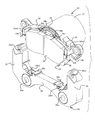
- FIG. 1 is an exploded perspective view showing the overall configuration of the disc brake device according to the first embodiment of the present invention.
- FIG. 2 is an exploded perspective view for explaining the configuration of the cylinder unit, the support, and the inner pad in the disc brake device according to the first embodiment of the present invention.
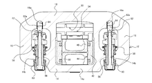
- FIG. 3 is a cross-sectional view showing the configuration of the cylinder unit arrangement side in the disc brake device according to the first embodiment of the present invention.
- FIG. 4 is a diagram showing a cross section along AA in FIG.
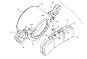
- FIG. 5 is a perspective view showing the relationship between the inner pad and the engaging member.
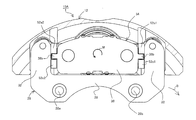
- FIG. 6 is a cross-sectional view showing the configuration of the cylinder unit arrangement side in the disc brake device according to the second embodiment of the present invention.
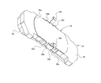
- FIG. 7 is a perspective view showing a configuration of a cylinder unit applied to a disc brake device according to a third embodiment of the present invention.
- FIG. 1 in the drawings is an exploded perspective view showing the configuration of the disc brake device according to the first embodiment of the present invention
- FIG. 2 is a diagram for explaining the configurations of the cylinder unit, the support, and the inner pad. It is a disassembled perspective view.
- FIG. 3 is a cross-sectional view showing the configuration on the cylinder unit arrangement side
- FIG. 4 is a cross-sectional view taken along the line AA in FIG.
- FIG. 5 is a perspective view showing the relationship between the inner pad and the engaging member.
- the disc brake device 10 is based on the body 12, the support 26, and the cylinder unit 40, and each of them is configured separately.
- the body 12 covers a support 26 and a cylinder unit 40, the details of which will be described later, and an outer brake pad (hereinafter simply referred to as the outer pad 20) on the sliding surface of the rotor by sliding in the axial direction of the rotor (not shown). It is a floating member that plays the role of pressing.
- the body 12 includes an inner body 14, an outer body 18, and a bridge 16.
- the inner body 14 is a part located on the side where the support 26 and the cylinder unit 40 are arranged with respect to the rotor when the body 12 is assembled.
- the inner body 14 is provided with a guide hole 14b.
- the pressure receiving portion 14a is a portion that is pressed from the inside by a second piston 50 disposed in a cylinder unit 40, which will be described in detail later.
- the guide hole 14b is a through-hole for inserting the fastening bolt 54 for holding the body 12 with respect to the support 26 described later in detail.
- the outer side body 18 is a part located on the opposite side of the support 26 from the rotor 26 as a base point when the body 12 is assembled.
- the outer pad 20 is disposed on the surface of the outer side body 18 facing the rotor.
- the outer pad 20 is basically composed of a lining 22 that is a friction member and a pressure plate 24 to which the lining 22 is attached, and the pressure plate 24 and the outer body 18 are fastened.
- a pin receiving portion 18 a that supports the tip of the fastening bolt 54 is provided on the side of the outer side body 18 facing the rotor.
- the bridge 16 is a part for connecting the inner side body 14 and the outer side body 18 described above, and is arranged so as to connect both on the outer peripheral side of the rotor.
- the bridge 16 disposed on the center side of the body 12 is divided as a main bridge, and the bridge 16 disposed outside the body 12 is referred to as a side bridge. And weight reduction (see FIG. 3).
- the support 26 plays a role for assembling the disc brake device 10 to a vehicle body (not shown).
- the support 26 according to the first embodiment is configured based on a bridge 28 and arm portions 30 and 32.
- the bridge 28 is a base member that is arranged toward the rotor entrance and exit sides, and is provided with a fastening hole 28a for fixing the support 26 to the vehicle. Further, the bridge 28 is provided with an inner peripheral side contact with a side located on the inner peripheral side in the radial direction of the rotor in a pressure plate 38 constituting an inner brake pad (hereinafter referred to simply as an inner pad 34), which will be described in detail later.
- Contact portions 28b1 and 28b2 are provided.
- the arm portions 30 and 32 are a pair of support portions that extend to the outer peripheral side in the radial direction of the rotor with the both ends of the rotor on the bridge 28 on the bridge 28 as base points.
- fixing positions 30a and 32a for fixing a cylinder unit 40 which will be described in detail later, are provided at the tips of the arm portions.
- through holes 30a1 and 32a1 for inserting fastening bolts 54 used when the cylinder unit 40 is fixed are formed.
- An inner pad 34 supported by the cylinder unit 40 is disposed between the pair of arm portions 30 and 32 as will be described in detail later.
- the inner pad 34 is basically composed of a lining 36 that is a friction member and a pressure plate 38.
- the cylinder unit 40 has a cylinder block 42 and a cylinder mounting portion 52.
- the cylinder block 42 has a penetrating inner cylinder (cylinder 44: see FIG. 4) and a bleeder hole 46 for supplying and discharging hydraulic oil from the outside of the cylinder block 42 to the cylinder 44.
- the cylinder unit 40 includes a first piston 48 and a second piston 50.
- 1st piston 48 (refer FIG. 2) is a piston for pressing the inner pad 34, and protrudes toward the arrangement direction of a rotor.
- the second piston 50 is a piston that protrudes toward the opposite side of the first piston 48 and presses the inner wall of the inner side body 14 in the body 12. For this reason, when hydraulic oil is supplied into the cylinder 44, the first piston 48 and the second piston 50 are pushed out in a relatively separated direction.
- both the 1st piston 48 and the 2nd piston 50 are made into the cup type form which has arrange
- the cylinder mounting portion 52 is a support portion that extends from the outer periphery of the cylinder block 42 in both the direction of the rotor entering and exiting in the assembled state.
- the cylinder block 42 is positioned by being fixed to.
- an outer peripheral side contact portion 52 a 1 on which a side located on the outer peripheral side in the radial direction of the rotor in the pressure plate 38 constituting the inner pad 34 contacts the cylinder mounting portion 52. 52a2 is provided.
- the outer peripheral side contact part 52a1, 52a2 will receive the rotational force (couple force) loaded on the inner pad 34 at the time of braking. Thereby, rotation of the inner pad 34 can be suppressed. Therefore, the load (twist) on the seal and boot in the first piston 48 can be suppressed, and deterioration of the seal and boot can be prevented.
- the body 12, the support 26, and the cylinder unit 40 having such a configuration are assembled via the fastening bolts 54.
- a sleeve 56 is disposed between the body 12 and the fastening bolt 54 and is held by boots 58 and 60 disposed before and after the sleeve 56. For this reason, there is little possibility that the torque input to the body 12 via the outer pad 20 will apply a load to the fastening bolt 54.
- the cylinder unit 40 is assembled to the support 26 by positioning by the sleeve 56, and the sleeve 56, the cylinder mounting portion 52, and the fastening bolt 54 through which the support 26 is inserted are screwed with a cap nut 62 formed in a pin shape. It is made by being combined.
- the pin 62a configured to have the outer shape of the cap nut 62 is slidably engaged with a pin receiving portion 18a formed on the outer body 18. Accordingly, when torque is input to the body 12 via the outer pad 20, the torque is transmitted to the support 26 via the cap nut 62.
- a clip 64 is disposed between the cap nut 62 and the pin receiving portion 18a in order to improve slidability and prevent wear during contact.
- the engaging member 39 is interposed on the contact surface between the inner pad 34 and the first piston 48 (see FIG. 5).
- the engaging member 39 is not particularly limited as long as the inner pad 34 can be engaged with the first piston 48, but the engaging member 39 may be configured as follows, for example. That is, the plate portion 39a, the pressure plate engaging claw 39b, and the first piston engaging claw 39c may be used.
- the plate portion 39a is a plate member that is disposed along the surface of the pressure plate 38 that faces the first piston 48.
- the pressure plate engaging claw 39b is a claw that engages with the pressure plate 38
- the first piston engaging claw 39c is a claw that engages with the inner peripheral portion of the first piston 48 that forms a cup-shaped body. is there.
- the first piston engaging claw 39c obtains an engaging force by urging the inner peripheral portion of the first piston 48 from the inner peripheral side toward the outer peripheral side. For this reason, it is set as the structure which provides the 1st piston engaging claw 39c with two or more at least 2, desirably 3 or more.
- the pressure plate 38 constituting the inner pad 34 has a stepped portion 38a for engaging the pressure plate engaging claw 39b in the engaging member 39. Is formed.
- the step portion 38a is provided on both the side of the pressure plate 38 located on the outer peripheral side in the radial direction of the rotor and the side located on the inner peripheral side, thereby ensuring the engagement of the engaging member 39. Can do.
- the specific shape of the stepped portion 38a is not limited, it is desirable that the stepped portion 38a is formed in a concave shape on the outer edge portion of the pressure plate 38 in the thickness direction. This is because such a configuration prevents the claw from projecting to the rotor side when the claw (pressure plate engaging claw 39b) of the engaging member 39 is engaged.
- the assembled state in which the first piston 48 holds the inner pad 34 can be obtained.
- the inner pad 34 can follow the movement of the first piston 48. For this reason, when the brake is released, the inner pad 34 also returns simultaneously with the return of the first piston 48, and dragging of the inner pad 34 can be suppressed.
- the shim 66 is interposed on the contact surface between the body 12 and the second piston 50.
- the shim 66 includes a shim plate main body 68, a clamping part 70, and a second piston engaging claw 72.
- the shim plate main body 68 plays the original role of the shim and improves the surface pressure between the body 12 and the second piston 50 even when there is a hardness difference between the constituent members of the body 12 and the second piston 50. be able to.
- the sandwiching portion 70 is a portion extending in a hook shape from the shim plate main body 68 toward the body 12 side, and by sandwiching the inner side body 14 between the shim plate main body 68 and the sandwiching portion 70, The shim 66 can be fixed.
- the second piston engaging claws 72 are a plurality of protrusions extending toward the second piston 50 with the shim plate body 68 as a base point.
- the shim 66 is configured to urge the inner peripheral portion of the second piston 50 from the inner peripheral side toward the outer peripheral side by the plurality of second piston engaging claws 72.
- the body 12 can follow the movement of the second piston 50. For this reason, when the brake is released, the body 12 also returns simultaneously with the return of the second piston 50, and dragging of the outer pad 20 fastened to the outer side body 18 can be suppressed.
- sliding members 52b and 28c are disposed between the inner pad 34 and the outer peripheral contact portions 52a1 and 52a2 and between the inner pad 34 and the inner peripheral contact portions 28b1 and 28b2, respectively.
- the disc brake device 10 having such a configuration, at the time of braking when the rotation direction of the rotor (not shown) is the direction of the arrow B shown in FIG. It abuts on the rotor turn-in side surface of 28b2. Due to the couple, a rotational moment in the direction indicated by the arrow M is generated in the pressure plate 38 and abuts on the inner peripheral side surface of the outer peripheral side contact portion 52a2 and the outer peripheral side surface of the inner peripheral side contact portion 28b1. . Therefore, in the disc brake device 10 according to the first embodiment, the torque caused by the inner pad 34 at the time of braking is received by the bridge 28 of the support 26. For this reason, in the floating type disc brake device 10, the torque of the inner pad 34 is not received by the fastening bolt 54. Further, the cylinder unit 40 can be assembled to the support 26 in a state where the inner pad 34 is assembled to the cylinder unit 40.
- the support 26 and the cylinder unit 40 are configured separately, the constituent materials of the two can be made different, and the balance between weight reduction and rigidity, ease of processing, and cost can be achieved.
- a structure in which the support 26 is made of aluminum and the cylinder unit 40 is made of cast iron can be adopted.
- the disc brake device 10 is configured to receive the braking torque applied by the inner pad 34 by the support bridge 28, and the braking torque by the inner pad 34 is applied to the arm portion 30. , 32 is not loaded. For this reason, it can prevent that the arm parts 30 and 32 spread to the delivery side of a rotor.
- the rotation of the inner pad 34 can be suppressed by receiving the rotational moment generated in the inner pad 34 at the outer peripheral contact portion 52a2 and the inner peripheral contact portion 28b1. Therefore, the rotation of the first piston 48 can be suppressed, and the load on the seal constituting the first piston can be reduced.
- the torque of the outer pad 20 is transmitted to the support 26 via the body 12 and the cap nut 62 having a short pin length. Therefore, on the outer pad 20 side, there is no need to worry about insufficient strength of the pin 62a (cap nut 62) that receives torque.
- the disc brake device 10 it is possible to reduce the load on the fastening bolt 54 and eliminate the fear of insufficient strength during braking.
- the operation of the first piston 48 and the second piston 50 is performed by supplying hydraulic oil into the cylinder 44.
- the operation of the first piston 48 and the second piston 50 may be performed in a form other than hydraulic pressure.
- an operation mechanism using electric power using a motor gear unit can be cited.
- the cylinder unit 40 is fixed to the support 26 that is a fixing member. For this reason, the weight of the body 12 can be reduced compared with the case where the motor gear unit is mounted on the body as the operating part, and a small, lightweight motor can be employed as the motor. Therefore, the weight of the entire disc brake device can be reduced.
- the cylinder unit 40 is fixed to the support 26 together with the fastening bolt 54 that holds the body 12.
- the cylinder unit 40 may be fixed to the support 26 by a fixing means different from the fastening bolt 54.
- the disc brake device 10A according to the first embodiment is almost the same as the disc brake device 10 according to the first embodiment described above. Therefore, portions having the same configuration are denoted by the same reference numerals as those in the first embodiment, and detailed description thereof is omitted.
- the difference from the disc brake device 10 according to the first embodiment is that the inner peripheral side contact portions 28b1 and 28b2 (see FIG. 3) provided on the support 26 in the first embodiment are cylinder units. This is a point provided in the cylinder mounting portion 52 constituting 40.
- the ear portion 38b is formed on the pressure plate 38 of the inner pad 34, and the outer peripheral side contact portions 52a1 and 52a2 are sandwiched between the ear portions 38b.
- the inner peripheral side contact portions 52c1 and 52c2 are arranged.
- the torque receiving surface is the rotor turn-in side surface of the outer peripheral side contact portions 52a1 and 52a2 (depending on the rotation direction of the rotor).
- the gap between the side surface of the pressure plate 38 and the rotor turn-in side surface in the outer peripheral side contact portions 52a1 and 52a2 is the same as the side surface of the pressure plate 38 and the rotor turn-in side surface in the inner peripheral side contact portions 52c1 and 52c2. It is comprised so that it may become smaller than the clearance gap. Further, the gap between the side surface of the pressure plate 38 and the rotor turn-in side surface in the outer peripheral side contact portions 52a1 and 52a2 is configured to be smaller than the gap between the end surface of the ear portion 38b and the arm portion 32 of the support 26. ing.
- the braking force comes into contact with the rotor turn-in side surface of the outer peripheral side contact portion 52a1.
- the torque receiving surface is higher than the center of gravity of the inner pad 34
- the rotational moment acting on the inner pad 34 works in the direction of the arrow M. Therefore, the rotational moment is received by the outer peripheral side surface of the inner peripheral side contact portion 52c2 and the inner peripheral side surface of the outer peripheral side contact portion 52a1.
- FIG. 7 shows the cylinder unit 40 which is the characteristic configuration and the inner pad 34 engaged therewith.
- the outer peripheral side contact portions 52a1 and 52a2 provided in the cylinder mounting portion 52 in the disc brake device 10 according to the first embodiment are provided in the cylinder block 42.
- the upper circumferential portion of the cylinder block 42 protrudes in the direction in which the inner pad 34 is arranged, and outer peripheral side contact portions 42a1 and 42a2 are provided on the protruding portion.
- the inner peripheral side abutting portion may be provided on the support 26 in the same manner as the disc brake device 10 according to the first embodiment described above.
- the body (12), the support (26), and the cylinder unit (40) are formed as separate bodies, and the support includes arm portions (30, 32) on both the return side and the return side of the rotor.
- the cylinder unit accommodates a first piston (48) and a second piston (50), and is provided with a cylinder mounting portion (52) for fixing to the arm portion.
- the disc brake device according to the above [1] (see FIG. 7), wherein the outer peripheral side contact portions (42a1, 42a2) are provided in a cylinder (42) constituting the cylinder unit (40).
- a brake pad for a disc brake device that is engaged with an engagement member (39) with respect to a cylinder unit (40) constituting the disc brake device (10), A disc brake in which a pressure plate (38) constituting the brake pad is formed with a stepped portion (38a) for engaging the engaging member (39) in the thickness direction of the pressure plate.
- Brake pad for the device (inner pad 34).
- this invention is not limited to embodiment mentioned above, A deformation
- the material, shape, dimensions, number, arrangement location, and the like of each component in the above-described embodiment are arbitrary and are not limited as long as the present invention can be achieved.
- This application is based on a Japanese patent application (Japanese Patent Application No. 2016-012999) filed on Jan. 27, 2016, the contents of which are incorporated herein by reference.
- the disc brake device of the present invention it is possible to reduce the load on the slide pin and eliminate the fear of insufficient rigidity during braking. Further, the brake pad for a disc brake device according to the present invention can be applied to the disc brake device having the above-described configuration, and the engaging portion when the engaging member is engaged is a lining that is a friction member. There is no risk of protruding to the side.
- inner pad inner brake pad
- 36 ......... lining, 38 ?? pressure plate, 38a ......... step part 38b ......... Ear portion, 39 ......... engaging member, 39a ......... plate portion, 39b ......... pressure plate engaging pawl, 39c ......... first piston engaging pawl, 40 ......... cylinder unit, 42 ......... Cylinder block, 42a1, 42a2 ......... Outer peripheral contact portion, 44 ......... Cylinder, 46 ......... Bleeder hole, 48 ......... First piston, 50 ......... Second piston, 52 ... .... Cylinder mounting part, 52a1, 52a2 ... Outer peripheral side contact part, 52b ......... Sliding member, 52c1, 52c2 .........
- Inner peripheral side contact part, 54 ......... Fastening bolt, 56 ......... Sleeve, 58 ......... Boot, 60 ......... Boot, 62 ......... Cap nut, 62a ......... Pin, 64 ?? Clip, 66 ......... Shim, 68 > Shim plate body, 70 ... ... clamping part, 72 ... ... 2nd piston engagement claw.
Landscapes
- Engineering & Computer Science (AREA)
- General Engineering & Computer Science (AREA)
- Mechanical Engineering (AREA)
- Braking Arrangements (AREA)
Abstract
ボディ(12)、サポート(26)、およびシリンダユニット(40)が別体で構成され、サポート(26)には、ロータの回入側と回出側の双方にアーム部(30)が設けられ、シリンダユニット(40)には、第1ピストン(48)と第2ピストン(50)が収容されると共に、アーム部(30)に対する固定を図るシリンダ取付部(52)が備えられているフローティング型のディスクブレーキ装置(10)であって、インナパッド(34)の半径方向外側に位置する辺が当接する外周側当接部(52a1,52a2)が、シリンダユニット(40)に設けられている。
Description
本発明は、ディスクブレーキ装置およびディスクブレーキ装置用ブレーキパッドに関する。
シリンダに、第1ピストンと第2ピストンの2つのピストンを備えるフローティング型のディスクブレーキ装置としては、特許文献1や特許文献2に開示されているものを挙げることができる。
特許文献1および特許文献2に開示されているディスクブレーキ装置ではいずれも、ブレーキパッドをスライドピンにより支持する構成が採られている。また、シリンダと、ディスクブレーキ装置を車両に固定するサポートとが一体形成され、この一体構造物により制動接線力(制動トルク)を受ける構成が採られている。
上記特許文献に開示されているディスクブレーキ装置では、いずれも、ロータの外周側に配置されるスライドピンにブレーキパッドが吊下げられる構成とされ、ボディや、スライドピンを支持するヨークのブリッジ部に大きな開口部が設けられる構成とされて、ディスクブレーキ装置全体の厚みが抑制されている。このため、制動時に必要とされる剛性を確保することが難しい。また、ブレーキパッドからの制動トルクをスライドピンのみで受けることとなる。このため、高速走行からの制動時などには、スライドピンの強度不足が懸念されると共に、ブレーキパッドがスライドピンに吊られた状態で支持されているため、偏摩耗の発生も懸念される。
そこで本発明では、スライドピンへの負荷を低減し、制動時の剛性不足の懸念を解消することができ、インナ側ブレーキパッドをシリンダユニットに組付けた状態でサポートに組付けることのできるディスクブレーキ装置と、このディスクブレーキ装置に適用するディスクブレーキ装置用ブレーキパッドを提供することを目的とする。
本発明の上記目的は、下記(1)~(8)の構成を有するディスクブレーキ装置により達成される。
(1) ボディ、サポート、およびシリンダユニットが別体で構成され、前記サポートには、ロータの回入側と回出側の双方にアーム部が設けられ、前記シリンダユニットには、第1ピストンと第2ピストンが収容されると共に、前記アーム部に対する固定を図るシリンダ取付部が備えられているフローティング型のディスクブレーキ装置であって、インナ側ブレーキパッドの半径方向外側に位置する辺が当接する外周側当接部が、前記シリンダユニットに設けられたディスクブレーキ装置。
(1) ボディ、サポート、およびシリンダユニットが別体で構成され、前記サポートには、ロータの回入側と回出側の双方にアーム部が設けられ、前記シリンダユニットには、第1ピストンと第2ピストンが収容されると共に、前記アーム部に対する固定を図るシリンダ取付部が備えられているフローティング型のディスクブレーキ装置であって、インナ側ブレーキパッドの半径方向外側に位置する辺が当接する外周側当接部が、前記シリンダユニットに設けられたディスクブレーキ装置。
(2) 前記外周側当接部は、前記シリンダ取付部に設けられている上記(1)に記載したディスクブレーキ装置。
(3) 前記外周側当接部は、前記シリンダユニットを構成するシリンダに設けられている上記(1)に記載したディスクブレーキ装置。
(4) 前記インナ側ブレーキパッドを構成するプレッシャプレートにおける前記ロータの半径方向内周側に位置する辺が当接する内周側当接部を有する上記(1)~(3)の何れか1つに記載したディスクブレーキ装置。
(5) 前記内周側当接部は、前記シリンダ取付部に設けられている上記(4)に記載のディスクブレーキ装置。
このような構成とすることによれば、係合部材が無い場合でも、インナ側ブレーキパッドをシリンダユニットに保持させることが可能となる。
このような構成とすることによれば、係合部材が無い場合でも、インナ側ブレーキパッドをシリンダユニットに保持させることが可能となる。
(6) 前記内周側当接部は、前記サポートに設けられている上記(4)に記載のディスクブレーキ装置。
このような構成とした際、内周側当接部をサポートのブリッジに設けることが可能となる。これにより、内周側当接部に制動時のトルク受けとしての役割を担わせることが可能となる。
このような構成とした際、内周側当接部をサポートのブリッジに設けることが可能となる。これにより、内周側当接部に制動時のトルク受けとしての役割を担わせることが可能となる。
(7) 前記シリンダユニットと前記インナ側ブレーキパッドとの間には、両者を係合する係合部材が設けられている上記(1)~(6)の何れか1つに記載したディスクブレーキ装置。
このような構成とすることによれば、制動解除時に、シリンダユニットの戻り動作と共にインナ側ブレーキパッドが引き戻されることとなる。よって、インナ側ブレーキパッドの引き摺りを抑制することができる。
このような構成とすることによれば、制動解除時に、シリンダユニットの戻り動作と共にインナ側ブレーキパッドが引き戻されることとなる。よって、インナ側ブレーキパッドの引き摺りを抑制することができる。
(8) 前記インナ側ブレーキパッドと前記外周側当接部および前記内周側当接部との間に、摺動部材が介在させられた上記(5)または(6)、或いは上記(6)または(6)を含む上記(7)に記載のディスクブレーキ装置。
このような構成とすることで、インナ側ブレーキパッドのロータ軸線方向への摺動性を向上させることができる。また、インナ側ブレーキパッドを構成するプレッシャプレートや、制動時にトルク受けとなる部位の摩滅を抑制することができる。
このような構成とすることで、インナ側ブレーキパッドのロータ軸線方向への摺動性を向上させることができる。また、インナ側ブレーキパッドを構成するプレッシャプレートや、制動時にトルク受けとなる部位の摩滅を抑制することができる。
また、本発明の上記目的は、下記(9)の構成を有するディスクブレーキ装置用ブレーキパッドにより達成される。
(9) ディスクブレーキ装置を構成するシリンダユニットに対して、係合部材を介して係合されるディスクブレーキ装置用ブレーキパッドであって、前記ブレーキパッドを構成するプレッシャプレートには、前記係合部材を係合させるための段差部が、前記プレッシャプレートの板厚方向に向けて形成されているディスクブレーキ装置用ブレーキパッド。
(9) ディスクブレーキ装置を構成するシリンダユニットに対して、係合部材を介して係合されるディスクブレーキ装置用ブレーキパッドであって、前記ブレーキパッドを構成するプレッシャプレートには、前記係合部材を係合させるための段差部が、前記プレッシャプレートの板厚方向に向けて形成されているディスクブレーキ装置用ブレーキパッド。
上記のような構成を有するディスクブレーキ装置によれば、スライドピンへの負荷を低減し、制動時の剛性不足の懸念を解消することができる。また、インナ側ブレーキパッドをシリンダユニットに組付けた状態でサポートへの組付けが可能となる。
また、上記のような構成を有するディスクブレーキ装置用ブレーキパッドによれば、上記構成を有するディスクブレーキ装置に適用することができ、係合部材を係合させた際の係合部(爪)が、摩擦部材であるライニング側に突出する虞が無い。
以下、本発明のディスクブレーキ装置に係る実施の形態について、図面を参照して詳細に説明する。なお、図面における図1は、本発明の第1の実施形態に係るディスクブレーキ装置の構成を示す分解斜視図であり、図2は、シリンダユニットとサポート、及びインナパッドの構成を説明するための分解斜視図である。また、図3は、シリンダユニット配置側の構成を示す断面図であり、図4は、図3におけるA-A断面を示す図である。さらに、図5は、インナパッドと係合部材の関係を示す斜視図である。
本第1の実施形態に係るディスクブレーキ装置10は、ボディ12とサポート26、及びシリンダユニット40を基本とし、それぞれが別体で構成されている。
ボディ12は、詳細を後述するサポート26、およびシリンダユニット40を覆うと共に、図示しないロータの軸線方向へのスライドにより、アウタ側ブレーキパッド(以下、単にアウタパッド20と称す)をロータの摺動面に押し付ける役割を担うフローティング部材である。
具体的な構成としては、ボディ12は、インナ側ボディ14とアウタ側ボディ18、およびブリッジ16を備える。インナ側ボディ14は、ボディ12が組み付けられた際、ロータを基準として、サポート26やシリンダユニット40が配置される側に位置する部位である。インナ側ボディ14には、受圧部14aの他に、ガイド孔14bが設けられている。受圧部14aは、詳細を後述するシリンダユニット40に配置される第2ピストン50により、内側から押圧される部位である。また、ガイド孔14bは、詳細を後述するサポート26に対してボディ12を保持するための締結ボルト54を挿通させるための貫通孔である。
アウタ側ボディ18は、ボディ12を組み付けた際、ロータを基点として、サポート26の配置側と反対側に位置する部位である。本第1の実施形態に係るディスクブレーキ装置10では、アウタ側ボディ18におけるロータとの対向面に、アウタパッド20が配置されている。
アウタパッド20は、摩擦部材であるライニング22と、ライニング22が貼付されているプレッシャプレート24とを基本として構成されており、プレッシャプレート24とアウタ側ボディ18が締結されることとなる。また、アウタ側ボディ18のロータへの対向面側には、締結ボルト54の先端を支持するピン受け部18aが設けられている。
ブリッジ16は、上述したインナ側ボディ14とアウタ側ボディ18とを連結するための部位であり、ロータの外周側で両者を連結するように配置されている。本第1の実施形態に係るボディ12では、ボディ12の中央側に配置したブリッジ16をメインブリッジ、ボディ12の外側に配置したブリッジ16をサイドブリッジと呼称するように分けることで、ボディの剛性と軽量化の双方を両立させている(図3参照)。ブリッジ16が設けられることにより、インナ側ボディ14が受けた押圧力がアウタ側ボディ18に伝達され、ロータの摺動面へのアウタパッド20の押し付けが可能となる。
サポート26は、ディスクブレーキ装置10を図示しない車両のボディに組付けるための役割を担う。本第1の実施形態に係るサポート26は、ブリッジ28と、アーム部30,32を基本として構成されている。ブリッジ28は、ロータの回入側と回出側に向けて配置されるベース部材であり、サポート26を車両に固定するための締結孔28aが設けられている。また、ブリッジ28には、詳細を後述するインナ側ブレーキパッド(以下、単にインナパッド34と称す)を構成するプレッシャプレート38におけるロータの半径方向内周側に位置する辺が当接する内周側当接部28b1,28b2が、設けられている。
アーム部30,32は、ブリッジ28におけるロータの回入側、回出側の両端部を基点として、ロータの半径方向外周側へ延設される一対の支持部である。本第1の実施形態に係るアーム部30,32の場合、各アーム部の先端に、詳細を後述するシリンダユニット40を固定するための固定位置30a,32aが設けられている。固定位置30a,32aには、シリンダユニット40を固定する際に用いられる締結ボルト54を挿通させるための貫通孔30a1,32a1が形成されている。
対を成すアーム部30,32の間には、詳細を後述するように、シリンダユニット40に支持されたインナパッド34が配置される。インナパッド34の構成も、アウタパッド20と同様に、摩擦部材であるライニング36と、プレッシャプレート38が基本とされている。
シリンダユニット40は、シリンダブロック42と、シリンダ取付部52とを有する。シリンダブロック42は、貫通形成された内筒(シリンダ44:図4参照)と、シリンダブロック42の外部からシリンダ44への作動油の供給・排出を行うためのブリーダ孔46を有する。シリンダユニット40には、第1ピストン48と第2ピストン50が備えられる。
第1ピストン48(図2参照)は、インナパッド34を押圧するためのピストンであり、ロータの配置方向へ向けて突出する。第2ピストン50は、第1ピストン48と反対側へ向けて突出し、ボディ12におけるインナ側ボディ14の内壁を押圧するピストンである。このため、第1ピストン48と第2ピストン50は、シリンダ44内に作動油が供給されると、相対的に離間する方向へと押し出されることとなる。なお、第1ピストン48と第2ピストン50は共に、開口部を突出方向に配置したカップ型の形態とされている。
シリンダ取付部52は、シリンダブロック42の外周を基点として、組付け状態においてロータの回入側と回出側となる方向の双方へ延設される支持部であり、シリンダ取付部52をサポート26に固定することで、シリンダブロック42の位置決めが成される。
本第1の実施形態では図2に示すように、シリンダ取付部52に、インナパッド34を構成するプレッシャプレート38におけるロータの半径方向外周側に位置する辺が当接する外周側当接部52a1,52a2が、設けられている。このような構成とすることで、制動時にインナパッド34に負荷される回転力(偶力)を外周側当接部52a1,52a2が受けることとなる。これにより、インナパッド34の回転を抑制することができる。よって、第1ピストン48におけるシールやブーツへの負荷(捻じれ)を抑制することができ、シールやブーツの劣化を防ぐことができる。
このような構成のボディ12、サポート26、およびシリンダユニット40は、締結ボルト54を介して組付けられる。ボディ12と締結ボルト54の間には、スリーブ56が配置され、スリーブ56の前後に配置されたブーツ58,60により保持される形態が採られる。このため、アウタパッド20を介してボディ12に入力されたトルクが締結ボルト54に負荷をかける虞が少ない。サポート26に対するシリンダユニット40の組み付けは、スリーブ56により位置決めが成されると共に、スリーブ56、シリンダ取付部52、およびサポート26を挿通させた締結ボルト54に、ピン状に形成した袋ナット62が螺合されることで成される。
袋ナット62の外形を有して構成されているピン62aは、アウタ側ボディ18に形成されたピン受け部18aに摺動可能に係合される。これにより、アウタパッド20を介してボディ12にトルクが入力された際、当該トルクは、袋ナット62を介してサポート26に伝達されることとなる。袋ナット62とピン受け部18aとの間には、摺動性の向上や当接時の摩滅を防ぐため、クリップ64が配置されている。
本第1の実施形態に係るディスクブレーキ装置10では、インナパッド34と第1ピストン48との当接面に係合部材39が介在されている(図5参照)。係合部材39は、インナパッド34を第1ピストン48に係合可能な形態であれば、その具体的構成を問うものでは無いが、例えば次のような構成とすることができる。すなわち、プレート部39aと、プレッシャプレート係合爪39b、及び第1ピストン係合爪39cを有する構成とすれば良い。プレート部39aは、プレッシャプレート38の第1ピストン48への対向面に沿って配置される板部材である。また、プレッシャプレート係合爪39bは、プレッシャプレート38に係合する爪であり、第1ピストン係合爪39cは、カップ型の体を成す第1ピストン48の内周部に係合する爪である。第1ピストン係合爪39cは、第1ピストン48の内周部に対して内周側から外周側へ向けて付勢することで、係合力を得る。このため、第1ピストン係合爪39cは、少なくとも2つ、望ましくは3つ以上の複数設ける構成とされている。
このような特徴に対応して、本第1の実施形態に係るインナパッド34を構成するプレッシャプレート38には、係合部材39におけるプレッシャプレート係合爪39bを係合させるための段差部38aが形成されている。段差部38aは、プレッシャプレート38におけるロータの半径方向外周側に位置する辺と、内周側に位置する辺の双方に設けられる事で、係合部材39の係合を確実なものとすることができる。
また、段差部38aの具体的形状については限定するものでは無いが、プレッシャプレート38の外縁部に、板厚方向に向けて凹状に形成することが望ましい。このような構成とすることで、係合部材39の爪(プレッシャプレート係合爪39b)を係合させる際、爪がロータ側に突出することが無いからである。
このような構成とすることで、第1ピストン48にインナパッド34を保持させる組付け状態とすることができる。また、ディスクブレーキ装置10を組み上げた状態においては、第1ピストン48の動きにインナパッド34を追従させることができる。このため、ブレーキ開放時に、第1ピストン48の戻りと同時にインナパッド34も戻ることとなり、インナパッド34の引き摺りを抑制することができる。
また、本第1の実施形態に係るディスクブレーキ装置10では、ボディ12と第2ピストン50との当接面に、シム66が介在されている。シム66は、シム板本体68と、挟持部70、および第2ピストン係合爪72とを有する。
シム板本体68は、シム本来の役割を担い、ボディ12と第2ピストン50との構成部材に硬度差がある場合であっても、ボディ12と第2ピストン50の間の面圧を改善することができる。挟持部70は、シム板本体68を基点としてボディ12側へ向けてフック状に延設された部位であり、シム板本体68と挟持部70との間にインナ側ボディ14を挟み込むことで、シム66の固定を図ることができる。また、第2ピストン係合爪72は、シム板本体68を基点として複数、第2ピストン50側へ向けて延設されている突起部である。シム66は、複数の第2ピストン係合爪72により、第2ピストン50の内周部に対して内周側から外周側へ向けて付勢する構成とされている。
このような構成とすることで、第2ピストン50の動きにボディ12を追従させることができる。このため、ブレーキ開放時に、第2ピストン50の戻りと同時にボディ12も戻ることとなり、アウタ側ボディ18に締結されているアウタパッド20の引き摺りを抑制することができる。
また、インナパッド34と外周側当接部52a1,52a2の間、およびインナパッド34と内周側当接部28b1,28b2の間には、それぞれ摺動部材52b,28cが配置されている。
このような構成のディスクブレーキ装置10では、図示しないロータの回転方向を図3に示す矢印Bの方向とした場合の制動時には、まず、インナパッド34のプレッシャプレート38が、内周側当接部28b2のロータ回入側側面に当接する。そして、偶力により、プレッシャプレート38には、矢印Mで示す方向の回転モーメントが生じ、外周側当接部52a2の内周側側面と、内周側当接部28b1の外周側側面に当接する。よって、本第1の実施形態に係るディスクブレーキ装置10では、制動時のインナパッド34に起因したトルクをサポート26のブリッジ28で受けることとなる。このため、フローティング型のディスクブレーキ装置10において、インナパッド34のトルクを締結ボルト54により受ける事が無くなる。また、インナパッド34をシリンダユニット40に組付けた状態で、シリンダユニット40をサポート26に組付けることができる。
また、サポート26とシリンダユニット40が別体で構成されることにより、両者の構成材料を異ならせることができ、軽量化と剛性、加工の容易性、およびコストのバランスを取ることができる。例えば、サポート26がアルミにより構成され、シリンダユニット40が鋳鉄により構成されるといった構造を採ることができる。
また、本第1の実施形態に係るディスクブレーキ装置10では上述したように、インナパッド34により負荷される制動トルクをサポートのブリッジ28で受ける構成とされ、インナパッド34による制動トルクがアーム部30,32に負荷されない構成とされている。このため、アーム部30,32がロータの回出側へ広がることを防ぐことができる。
また、インナパッド34に生ずる回転モーメントを外周側当接部52a2と、内周側当接部28b1で受けることで、インナパッド34の回転を抑制することができる。そこで、第1ピストン48が回転する事を抑制することができ、第1ピストンを構成するシールへの負荷を小さくすることができる。
また、アウタパッド20のトルクは、ボディ12を介してピン長の短い袋ナット62を介してサポート26に伝達される。よって、アウタパッド20側においても、トルクを受けるピン62a(袋ナット62)の強度不足を懸念する必要性が無い。
このため、本第1の実施形態に係るディスクブレーキ装置10によれば、締結ボルト54への負荷を低減し、制動時の強度不足の懸念を解消することができる。
また、上記第1の実施形態では、第1ピストン48、および第2ピストン50の稼働について、シリンダ44内に作動油を供給することで成される旨記載した。しかしながら、第1ピストン48と第2ピストン50の稼働は、油圧以外の形式により行うようにしても良い。このような構成とすることで、油圧ユニットが使用できない環境下においても、本発明に係るディスクブレーキ装置を適用することが可能となり、より汎用性を向上させることが可能となるからである。
油圧以外の作動形式の具体的な一例として、モータギヤユニットを用いた電力による稼働機構の採用を挙げることができる。
本第1の実施形態に係るディスクブレーキ装置10では、シリンダユニット40が、固定部材であるサポート26に固定されている。このため、稼働部であるボディにモータギヤユニットを搭載する場合に比べ、ボディ12の重量を軽くすることができ、モータとして、出力が小さく、小型軽量なものを採用することができる。よって、ディスクブレーキ装置全体の軽量化を図ることができる。
また、上記第1の実施形態では、サポート26に対するシリンダユニット40の固定について、ボディ12を保持する締結ボルト54により共締めする構成とする旨記載した。しかしながら、締結ボルト54とは別の固定手段によりサポート26に対してシリンダユニット40を固定するようにしても良い。
次に、図6を参照して、本発明の第2の実施形態に係るディスクブレーキ装置について説明する。本第1の実施形態に係るディスクブレーキ装置10Aも、その殆どの構成は、上述した第1の実施形態に係るディスクブレーキ装置10と同様である。よって、その構成を同一とする箇所には、第1の実施形態と同一の符号を付して、その詳細な説明を省略することとする。
本第1の実施形態に係るディスクブレーキ装置10との相違点としては、第1の実施形態ではサポート26に設けられていた内周側当接部28b1,28b2(図3参照)が、シリンダユニット40を構成するシリンダ取付部52に設けられる構成とされている点である。
すなわち、本第2の実施形態に係るディスクブレーキ装置10Aでは、インナパッド34のプレッシャプレート38に耳部38bが形成され、この耳部38bを挟み込むように、外周側当接部52a1,52a2と、内周側当接部52c1,52c2とが配置される構成とされている。また、本第2の実施形態に係るディスクブレーキ装置10Aは、トルク受け面が外周側当接部52a1,52a2のロータ回入側側面(ロータの回転方向によって異なる)とされている。このため、プレッシャプレート38の側面と外周側当接部52a1,52a2におけるロータ回入側側面との隙間が、プレッシャプレート38の側面と内周側当接部52c1,52c2におけるロータ回入側側面との隙間よりも小さくなるように構成されている。また、プレッシャプレート38の側面と外周側当接部52a1,52a2におけるロータ回入側側面との隙間は、耳部38bの端面とサポート26のアーム部32との隙間よりも小さくなるように構成されている。
このような構成のディスクブレーキ装置10Aでは、ロータの回転方向を矢印Bの方向とした場合の制動時に、外周側当接部52a1のロータ回入側側面に当接して制動トルクを受けることとなる。ここで、トルク受け面がインナパッド34の重心点よりも高い場合、インナパッド34に作用する回転モーメントは、矢印Mの方向に働くこととなる。よって、回転モーメントは、内周側当接部52c2の外周側側面と、外周側当接部52a1の内周側側面により受けることとなる。
このような構成のディスクブレーキ装置10Aであっても、上記第1の実施形態と同様の効果を得ることができる。
次に、図7を参照して、本発明の第3の実施形態に係るディスクブレーキ装置について説明する。本第3の実施形態に係るディスクブレーキ装置は、第1の実施形態に係るディスクブレーキ装置10をベースとして、シリンダユニット40の構成を変更したものである。よって、図7には、その特徴的な構成であるシリンダユニット40と、これに係合するインナパッド34を示すこととする。
本第3の実施形態では、第1の実施形態に係るディスクブレーキ装置10ではシリンダ取付部52に設けていた外周側当接部52a1,52a2が、シリンダブロック42に設けられる構成とされている。具体的には、シリンダブロック42の上部円周部がインナパッド34の配置方向へ突出され、この突出部に外周側当接部42a1,42a2が設けられている。内周側当接部は、上述した第1の実施形態に係るディスクブレーキ装置10と同様に、サポート26に設けるようにすると良い。
このような構成のディスクブレーキ装置であっても、上記第1、第2の実施形態と同様の効果を得ることができる。
ここで、上述した本発明に係るディスクブレーキ装置およびディスクブレーキ装置用ブレーキパッドの実施の形態の特徴をそれぞれ以下に簡潔に纏めて列記する。
[1] ボディ(12)、サポート(26)、およびシリンダユニット(40)が別体で構成され、前記サポートには、ロータの回入側と回出側の双方にアーム部(30,32)が設けられ、前記シリンダユニットには、第1ピストン(48)と第2ピストン(50)が収容されると共に、前記アーム部に対する固定を図るシリンダ取付部(52)が備えられているフローティング型のディスクブレーキ装置であって、
インナ側ブレーキパッド(インナパッド34)の半径方向外側に位置する辺が当接する外周側当接部(52a1,52a2、42a1,42a2)が、前記シリンダユニットに設けられたディスクブレーキ装置(10、10A)。
[2] 前記外周側当接部(52a1,52a2)は、前記シリンダ取付部(52)に設けられている上記[1]に記載のディスクブレーキ装置(10、10A)。
[3] 前記外周側当接部(42a1,42a2)は、前記シリンダユニット(40)を構成するシリンダ(42)に設けられている上記[1]に記載のディスクブレーキ装置(図7参照)。
[4] 前記インナ側ブレーキパッド(インナパッド34)を構成するプレッシャプレート(38)における前記ロータの半径方向内周側に位置する辺が当接する内周側当接部(28b1,28b2、52c1,52c2)を有する上記[1]~[3]のいずれか1つに記載のディスクブレーキ装置(10、10A)。
[5] 前記内周側当接部(52c1,52c2)は、前記シリンダ取付部(52)に設けられている上記[4]に記載のディスクブレーキ装置(10A)。
[6] 前記内周側当接部(28b1,28b2)は、前記サポート(26)に設けられている上記[4]に記載のディスクブレーキ装置(10)。
[7] 前記シリンダユニット(40)と前記インナ側ブレーキパッド(インナパッド34)との間には、両者を係合する係合部材(39)が設けられている上記[1]~[6]のいずれか1つに記載のディスクブレーキ装置(10)。
[8] 前記インナ側ブレーキパッド(インナパッド34)と前記外周側当接部(52a1,52a2)および前記内周側当接部(28b1,28b2)との間に、摺動部材(52b,28c)が介在させられた上記[5]または[6]、或いは上記[5]または[6]を含む上記[7]に記載のディスクブレーキ装置(10)。
[9] ディスクブレーキ装置(10)を構成するシリンダユニット(40)に対して、係合部材(39)を介して係合されるディスクブレーキ装置用ブレーキパッドであって、
前記ブレーキパッドを構成するプレッシャプレート(38)には、前記係合部材(39)を係合させるための段差部(38a)が、前記プレッシャプレートの板厚方向に向けて形成されているディスクブレーキ装置用ブレーキパッド(インナパッド34)。
[1] ボディ(12)、サポート(26)、およびシリンダユニット(40)が別体で構成され、前記サポートには、ロータの回入側と回出側の双方にアーム部(30,32)が設けられ、前記シリンダユニットには、第1ピストン(48)と第2ピストン(50)が収容されると共に、前記アーム部に対する固定を図るシリンダ取付部(52)が備えられているフローティング型のディスクブレーキ装置であって、
インナ側ブレーキパッド(インナパッド34)の半径方向外側に位置する辺が当接する外周側当接部(52a1,52a2、42a1,42a2)が、前記シリンダユニットに設けられたディスクブレーキ装置(10、10A)。
[2] 前記外周側当接部(52a1,52a2)は、前記シリンダ取付部(52)に設けられている上記[1]に記載のディスクブレーキ装置(10、10A)。
[3] 前記外周側当接部(42a1,42a2)は、前記シリンダユニット(40)を構成するシリンダ(42)に設けられている上記[1]に記載のディスクブレーキ装置(図7参照)。
[4] 前記インナ側ブレーキパッド(インナパッド34)を構成するプレッシャプレート(38)における前記ロータの半径方向内周側に位置する辺が当接する内周側当接部(28b1,28b2、52c1,52c2)を有する上記[1]~[3]のいずれか1つに記載のディスクブレーキ装置(10、10A)。
[5] 前記内周側当接部(52c1,52c2)は、前記シリンダ取付部(52)に設けられている上記[4]に記載のディスクブレーキ装置(10A)。
[6] 前記内周側当接部(28b1,28b2)は、前記サポート(26)に設けられている上記[4]に記載のディスクブレーキ装置(10)。
[7] 前記シリンダユニット(40)と前記インナ側ブレーキパッド(インナパッド34)との間には、両者を係合する係合部材(39)が設けられている上記[1]~[6]のいずれか1つに記載のディスクブレーキ装置(10)。
[8] 前記インナ側ブレーキパッド(インナパッド34)と前記外周側当接部(52a1,52a2)および前記内周側当接部(28b1,28b2)との間に、摺動部材(52b,28c)が介在させられた上記[5]または[6]、或いは上記[5]または[6]を含む上記[7]に記載のディスクブレーキ装置(10)。
[9] ディスクブレーキ装置(10)を構成するシリンダユニット(40)に対して、係合部材(39)を介して係合されるディスクブレーキ装置用ブレーキパッドであって、
前記ブレーキパッドを構成するプレッシャプレート(38)には、前記係合部材(39)を係合させるための段差部(38a)が、前記プレッシャプレートの板厚方向に向けて形成されているディスクブレーキ装置用ブレーキパッド(インナパッド34)。
なお、本発明は、上述した実施形態に限定されるものではなく、適宜、変形、改良、等が可能である。その他、上述した実施形態における各構成要素の材質、形状、寸法、数、配置箇所、等は本発明を達成できるものであれば任意であり、限定されない。
また、本出願は、2016年1月27日出願の日本特許出願(特願2016-012999)に基づくものであり、その内容はここに参照として取り込まれる。
また、本出願は、2016年1月27日出願の日本特許出願(特願2016-012999)に基づくものであり、その内容はここに参照として取り込まれる。
本発明に係るディスクブレーキ装置によれば、スライドピンへの負荷を低減し、制動時の剛性不足の懸念を解消することができる。
また、本発明に係るディスクブレーキ装置用ブレーキパッドによれば、上記構成を有するディスクブレーキ装置に適用することができ、係合部材を係合させた際の係合部が、摩擦部材であるライニング側に突出する虞が無い。
また、本発明に係るディスクブレーキ装置用ブレーキパッドによれば、上記構成を有するディスクブレーキ装置に適用することができ、係合部材を係合させた際の係合部が、摩擦部材であるライニング側に突出する虞が無い。
10,10A………ディスクブレーキ装置、12………ボディ、14………インナ側ボディ、14a………受圧部、14b………ガイド孔、16………ブリッジ、18………アウタ側ボディ、18a………ピン受け部、20………アウタパッド(アウタ側ブレーキパッド)、22………ライニング、24………プレッシャプレート、26………サポート、28………ブリッジ、28a………締結孔、28b1,28b2………内周側当接部、28c………摺動部材、30………アーム部、30a………固定位置、30a1………貫通孔、32………アーム部、32a………固定位置、32a1………貫通孔、34………インナパッド(インナ側ブレーキパッド)、36………ライニング、38………プレッシャプレート、38a………段差部、38b………耳部、39………係合部材、39a………プレート部、39b………プレッシャプレート係合爪、39c………第1ピストン係合爪、40………シリンダユニット、42………シリンダブロック、42a1,42a2………外周側当接部、44………シリンダ、46………ブリーダ孔、48………第1ピストン、50………第2ピストン、52………シリンダ取付部、52a1,52a2………外周側当接部、52b………摺動部材、52c1,52c2………内周側当接部、54………締結ボルト、56………スリーブ、58………ブーツ、60………ブーツ、62………袋ナット、62a………ピン、64………クリップ、66………シム、68………シム板本体、70………挟持部、72………第2ピストン係合爪。
Claims (9)
- ボディ、サポート、およびシリンダユニットが別体で構成され、前記サポートには、ロータの回入側と回出側の双方にアーム部が設けられ、前記シリンダユニットには、第1ピストンと第2ピストンが収容されると共に、前記アーム部に対する固定を図るシリンダ取付部が備えられているフローティング型のディスクブレーキ装置であって、
インナ側ブレーキパッドの半径方向外側に位置する辺が当接する外周側当接部が、前記シリンダユニットに設けられたディスクブレーキ装置。 - 前記外周側当接部は、前記シリンダ取付部に設けられている請求項1に記載のディスクブレーキ装置。
- 前記外周側当接部は、前記シリンダユニットを構成するシリンダに設けられている請求項1に記載のディスクブレーキ装置。
- 前記インナ側ブレーキパッドを構成するプレッシャプレートにおける前記ロータの半径方向内周側に位置する辺が当接する内周側当接部を有する請求項1乃至3のいずれか1項に記載のディスクブレーキ装置。
- 前記内周側当接部は、前記シリンダ取付部に設けられている請求項4に記載のディスクブレーキ装置。
- 前記内周側当接部は、前記サポートに設けられている請求項4に記載のディスクブレーキ装置。
- 前記シリンダユニットと前記インナ側ブレーキパッドとの間には、両者を係合する係合部材が設けられている請求項1乃至6のいずれか1項に記載のディスクブレーキ装置。
- 前記インナ側ブレーキパッドと前記外周側当接部および前記内周側当接部との間に、摺動部材が介在させられた請求項5または6、或いは請求項5または6を含む請求項7に記載のディスクブレーキ装置。
- ディスクブレーキ装置を構成するシリンダユニットに対して、係合部材を介して係合されるディスクブレーキ装置用ブレーキパッドであって、
前記ブレーキパッドを構成するプレッシャプレートには、前記係合部材を係合させるための段差部が、前記プレッシャプレートの板厚方向に向けて形成されているディスクブレーキ装置用ブレーキパッド。
Applications Claiming Priority (2)
| Application Number | Priority Date | Filing Date | Title |
|---|---|---|---|
| JP2016012999A JP2017133579A (ja) | 2016-01-27 | 2016-01-27 | ディスクブレーキ装置およびディスクブレーキ装置用ブレーキパッド |
| JP2016-012999 | 2016-01-27 |
Publications (1)
| Publication Number | Publication Date |
|---|---|
| WO2017130628A1 true WO2017130628A1 (ja) | 2017-08-03 |
Family
ID=59397848
Family Applications (1)
| Application Number | Title | Priority Date | Filing Date |
|---|---|---|---|
| PCT/JP2016/089002 Ceased WO2017130628A1 (ja) | 2016-01-27 | 2016-12-27 | ディスクブレーキ装置およびディスクブレーキ装置用ブレーキパッド |
Country Status (2)
| Country | Link |
|---|---|
| JP (1) | JP2017133579A (ja) |
| WO (1) | WO2017130628A1 (ja) |
Cited By (3)
| Publication number | Priority date | Publication date | Assignee | Title |
|---|---|---|---|---|
| DE102019101219A1 (de) * | 2019-01-17 | 2020-07-23 | Wabco Europe Bvba | Bremsenträger und Bremsbelag für Scheibenbremsen von Nutzahrzeugen |
| DE102021206055A1 (de) | 2021-06-15 | 2022-12-15 | Zf Active Safety Gmbh | Bremsbelaganordnung für eine Fahrzeugscheibenbremse |
| GB2614226A (en) * | 2021-09-14 | 2023-07-05 | Ap Racing Ltd | Braking system |
Citations (3)
| Publication number | Priority date | Publication date | Assignee | Title |
|---|---|---|---|---|
| JP2013181646A (ja) * | 2012-03-05 | 2013-09-12 | Toyota Motor Corp | ブレーキ装置 |
| WO2015137359A1 (ja) * | 2014-03-10 | 2015-09-17 | 曙ブレーキ工業株式会社 | フローティング型ディスクブレーキ |
| JP2015232341A (ja) * | 2014-06-09 | 2015-12-24 | 曙ブレーキ工業株式会社 | ディスクブレーキ用パッド組立体 |
-
2016
- 2016-01-27 JP JP2016012999A patent/JP2017133579A/ja active Pending
- 2016-12-27 WO PCT/JP2016/089002 patent/WO2017130628A1/ja not_active Ceased
Patent Citations (3)
| Publication number | Priority date | Publication date | Assignee | Title |
|---|---|---|---|---|
| JP2013181646A (ja) * | 2012-03-05 | 2013-09-12 | Toyota Motor Corp | ブレーキ装置 |
| WO2015137359A1 (ja) * | 2014-03-10 | 2015-09-17 | 曙ブレーキ工業株式会社 | フローティング型ディスクブレーキ |
| JP2015232341A (ja) * | 2014-06-09 | 2015-12-24 | 曙ブレーキ工業株式会社 | ディスクブレーキ用パッド組立体 |
Cited By (3)
| Publication number | Priority date | Publication date | Assignee | Title |
|---|---|---|---|---|
| DE102019101219A1 (de) * | 2019-01-17 | 2020-07-23 | Wabco Europe Bvba | Bremsenträger und Bremsbelag für Scheibenbremsen von Nutzahrzeugen |
| DE102021206055A1 (de) | 2021-06-15 | 2022-12-15 | Zf Active Safety Gmbh | Bremsbelaganordnung für eine Fahrzeugscheibenbremse |
| GB2614226A (en) * | 2021-09-14 | 2023-07-05 | Ap Racing Ltd | Braking system |
Also Published As
| Publication number | Publication date |
|---|---|
| JP2017133579A (ja) | 2017-08-03 |
Similar Documents
| Publication | Publication Date | Title |
|---|---|---|
| CN104271978B (zh) | 带有复位装置的盘式制动器和制动衬片 | |
| JP2015124812A (ja) | ディスクブレーキ装置 | |
| US11105385B2 (en) | Twin piston caliper with electric parking brake and method of operating such a twin piston caliper with electric parking brake | |
| CN107850143B (zh) | 盘式制动器装置 | |
| CN107002787A (zh) | 盘式制动器装置 | |
| US11287000B2 (en) | Vehicular disc brake | |
| WO2017130628A1 (ja) | ディスクブレーキ装置およびディスクブレーキ装置用ブレーキパッド | |
| JP2014190478A (ja) | ディスクブレーキ装置 | |
| US10550904B2 (en) | Disc brake for a commercial vehicle | |
| JP6202434B2 (ja) | ディスクブレーキ装置 | |
| US6382368B2 (en) | Drum-in disc brake | |
| EP3680502A1 (en) | Caliper for opposed piston-type disc brake | |
| JP4521453B2 (ja) | 車両用ディスクブレーキのキャリパボディ支持構造 | |
| JP5544263B2 (ja) | ブレーキパッド | |
| KR102642274B1 (ko) | 유동형 캘리퍼 디스크 브레이크 | |
| WO2010137520A1 (ja) | 車両用ディスクブレーキのキャリパボディ支持構造 | |
| JP2016079986A (ja) | ディスクブレーキ装置 | |
| JP4581909B2 (ja) | ディスクブレーキ | |
| JP5603797B2 (ja) | 車両用ディスクブレーキ | |
| WO2017006803A1 (ja) | ディスクブレーキ装置 | |
| KR100855953B1 (ko) | 디스크 브레이크 | |
| JP2017020557A (ja) | ディスクブレーキ装置およびディスクブレーキ装置用接続部材 | |
| JP2009180265A (ja) | ディスクブレーキ | |
| JP4288197B2 (ja) | 車両用ディスクブレーキ | |
| CA2943390A1 (en) | Brake piston head for a disc brake device, brake piston and disc brake device |
Legal Events
| Date | Code | Title | Description |
|---|---|---|---|
| 121 | Ep: the epo has been informed by wipo that ep was designated in this application |
Ref document number: 16888212 Country of ref document: EP Kind code of ref document: A1 |
|
| NENP | Non-entry into the national phase |
Ref country code: DE |
|
| 122 | Ep: pct application non-entry in european phase |
Ref document number: 16888212 Country of ref document: EP Kind code of ref document: A1 |