WO2017130429A1 - 車両用骨格部材の製造方法 - Google Patents
車両用骨格部材の製造方法 Download PDFInfo
- Publication number
- WO2017130429A1 WO2017130429A1 PCT/JP2016/064161 JP2016064161W WO2017130429A1 WO 2017130429 A1 WO2017130429 A1 WO 2017130429A1 JP 2016064161 W JP2016064161 W JP 2016064161W WO 2017130429 A1 WO2017130429 A1 WO 2017130429A1
- Authority
- WO
- WIPO (PCT)
- Prior art keywords
- plate
- vehicle
- portions
- groove
- impact beam
- Prior art date
- Legal status (The legal status is an assumption and is not a legal conclusion. Google has not performed a legal analysis and makes no representation as to the accuracy of the status listed.)
- Ceased
Links
Images













Classifications
-
- B—PERFORMING OPERATIONS; TRANSPORTING
- B21—MECHANICAL METAL-WORKING WITHOUT ESSENTIALLY REMOVING MATERIAL; PUNCHING METAL
- B21D—WORKING OR PROCESSING OF SHEET METAL OR METAL TUBES, RODS OR PROFILES WITHOUT ESSENTIALLY REMOVING MATERIAL; PUNCHING METAL
- B21D47/00—Making rigid structural elements or units, e.g. honeycomb structures
- B21D47/01—Making rigid structural elements or units, e.g. honeycomb structures beams or pillars
-
- B—PERFORMING OPERATIONS; TRANSPORTING
- B21—MECHANICAL METAL-WORKING WITHOUT ESSENTIALLY REMOVING MATERIAL; PUNCHING METAL
- B21C—MANUFACTURE OF METAL SHEETS, WIRE, RODS, TUBES, PROFILES OR LIKE SEMI-MANUFACTURED PRODUCTS OTHERWISE THAN BY ROLLING; AUXILIARY OPERATIONS USED IN CONNECTION WITH METAL-WORKING WITHOUT ESSENTIALLY REMOVING MATERIAL
- B21C23/00—Extruding metal; Impact extrusion
- B21C23/02—Making uncoated products
- B21C23/04—Making uncoated products by direct extrusion
- B21C23/14—Making other products
- B21C23/142—Making profiles
-
- B—PERFORMING OPERATIONS; TRANSPORTING
- B21—MECHANICAL METAL-WORKING WITHOUT ESSENTIALLY REMOVING MATERIAL; PUNCHING METAL
- B21D—WORKING OR PROCESSING OF SHEET METAL OR METAL TUBES, RODS OR PROFILES WITHOUT ESSENTIALLY REMOVING MATERIAL; PUNCHING METAL
- B21D22/00—Shaping without cutting, by stamping, spinning, or deep-drawing
- B21D22/02—Stamping using rigid devices or tools
-
- B—PERFORMING OPERATIONS; TRANSPORTING
- B21—MECHANICAL METAL-WORKING WITHOUT ESSENTIALLY REMOVING MATERIAL; PUNCHING METAL
- B21D—WORKING OR PROCESSING OF SHEET METAL OR METAL TUBES, RODS OR PROFILES WITHOUT ESSENTIALLY REMOVING MATERIAL; PUNCHING METAL
- B21D35/00—Combined processes according to or processes combined with methods covered by groups B21D1/00 - B21D31/00
- B21D35/002—Processes combined with methods covered by groups B21D1/00 - B21D31/00
- B21D35/005—Processes combined with methods covered by groups B21D1/00 - B21D31/00 characterized by the material of the blank or the workpiece
- B21D35/006—Blanks having varying thickness, e.g. tailored blanks
-
- B—PERFORMING OPERATIONS; TRANSPORTING
- B21—MECHANICAL METAL-WORKING WITHOUT ESSENTIALLY REMOVING MATERIAL; PUNCHING METAL
- B21D—WORKING OR PROCESSING OF SHEET METAL OR METAL TUBES, RODS OR PROFILES WITHOUT ESSENTIALLY REMOVING MATERIAL; PUNCHING METAL
- B21D53/00—Making other particular articles
- B21D53/88—Making other particular articles other parts for vehicles, e.g. cowlings, mudguards
-
- B—PERFORMING OPERATIONS; TRANSPORTING
- B60—VEHICLES IN GENERAL
- B60J—WINDOWS, WINDSCREENS, NON-FIXED ROOFS, DOORS, OR SIMILAR DEVICES FOR VEHICLES; REMOVABLE EXTERNAL PROTECTIVE COVERINGS SPECIALLY ADAPTED FOR VEHICLES
- B60J5/00—Doors
- B60J5/04—Doors arranged at the vehicle sides
- B60J5/042—Reinforcement elements
- B60J5/0422—Elongated type elements, e.g. beams, cables, belts or wires
- B60J5/0438—Elongated type elements, e.g. beams, cables, belts or wires characterised by the type of elongated elements
- B60J5/0443—Beams
-
- B—PERFORMING OPERATIONS; TRANSPORTING
- B60—VEHICLES IN GENERAL
- B60J—WINDOWS, WINDSCREENS, NON-FIXED ROOFS, DOORS, OR SIMILAR DEVICES FOR VEHICLES; REMOVABLE EXTERNAL PROTECTIVE COVERINGS SPECIALLY ADAPTED FOR VEHICLES
- B60J5/00—Doors
- B60J5/04—Doors arranged at the vehicle sides
- B60J5/042—Reinforcement elements
- B60J5/0422—Elongated type elements, e.g. beams, cables, belts or wires
- B60J5/0438—Elongated type elements, e.g. beams, cables, belts or wires characterised by the type of elongated elements
- B60J5/0443—Beams
- B60J5/0444—Beams characterised by a special cross section
-
- B—PERFORMING OPERATIONS; TRANSPORTING
- B62—LAND VEHICLES FOR TRAVELLING OTHERWISE THAN ON RAILS
- B62D—MOTOR VEHICLES; TRAILERS
- B62D25/00—Superstructure or monocoque structure sub-units; Parts or details thereof not otherwise provided for
- B62D25/04—Door pillars ; windshield pillars
-
- B—PERFORMING OPERATIONS; TRANSPORTING
- B62—LAND VEHICLES FOR TRAVELLING OTHERWISE THAN ON RAILS
- B62D—MOTOR VEHICLES; TRAILERS
- B62D29/00—Superstructures, understructures, or sub-units thereof, characterised by the material thereof
- B62D29/008—Superstructures, understructures, or sub-units thereof, characterised by the material thereof predominantly of light alloys, e.g. extruded
Definitions
- the present invention relates to a method of manufacturing a framework member for a vehicle.
- the door impact beam for vehicles attached to the inside of the door for vehicles as one of the frame members for vehicles is known.
- the vehicle door impact beam absorbs an impact applied to the vehicle door, and suppresses a large deformation of the vehicle door.
- the door impact beam for vehicles of patent documents 1 and 2 is formed cylindrical. That is, these vehicle door impact beams have an inner wall portion disposed on the inner panel side of the vehicle door and an outer wall portion disposed on the outer panel side of the vehicle door. The inner and outer wall portions extend in parallel and face each other. In addition, these vehicle door impact beams have a pair of side wall portions formed between the inner wall portion and the outer wall portion and connecting the inner wall portion and the outer wall portion. In other words, these vehicle door impact beams have a hollow portion surrounded by the inner wall portion, the outer wall portion and the side wall portion described above. These vehicle door impact beams are made of aluminum alloy. These vehicle door impact beams are manufactured using an extrusion method.
- the door impact beam for vehicles of patent document 3 is installed in the predetermined direction, and is formed in the groove shape open
- the side wall portions are connected to both widthwise end portions of the bottom wall portion and face each other.
- a flange portion extending to the outside of the groove (outside of the space surrounded by the bottom wall portion and the side wall portion) is formed.
- the recessed part (groove part) extended in the longitudinal direction is formed in the surface by the side of the outer panel of a bottom wall part. That is, this recessed part is open
- This vehicle door impact beam is manufactured by press-forming a strip-like metal steel plate.
- the space in the vehicle door is narrow.
- the dimension in the vehicle width direction of the portion where the front end portion and the rear end portion of the vehicle door impact beam are arranged (that is, the front end portion and the rear end portion of the vehicle door) is small. Therefore, when the vehicle door impact beam is manufactured using the extrusion molding method as in Patent Document 1 or 2, the dimensions of the vehicle door impact beam in the vehicle width direction are set to the front end portion and the rear end of the vehicle door. If the size of the space in the vehicle width direction is set small, it is necessary to increase the thickness of each wall of the vehicle door impact beam in order to ensure sufficient strength of the vehicle door impact beam. Therefore, the weight of the vehicle door impact beam is relatively large.
- the dimension in the vehicle width direction of the space in the vicinity of the middle portion of the vehicle door impact beam in the vehicle door is larger than that of the space in which the front end and the rear end are arranged. Therefore, the following manufacturing method can be considered.
- an extrusion-molding method is used to manufacture an intermediately-formed intermediate member.
- the dimension in the vehicle width direction of the intermediate formed member is larger than the dimension in the vehicle width direction of the space at the front end portion and the rear end portion of the vehicle door.
- the dimensions of the front end portion and the rear end portion in the vehicle width direction are reduced by squashing (press forming) the front end portion and the rear end portion of the intermediate forming member in the vehicle width direction.
- the dimension in the vehicle width direction of the front end portion and the rear end portion of the vehicle door impact beam can be made smaller than that of the middle portion.
- brackets are attached to the front end portion and the rear end portion of the vehicle door impact beam, and the vehicle door is mounted via the bracket It is necessary to attach the impact beam to the vehicle door.
- vertical to the longitudinal direction of the door impact beam for vehicles of patent document 3 is constant. That is, the plate thickness of the portion (for example, the side wall portion of the groove) which has little influence on the strength of the vehicle door impact beam is unnecessarily large. Therefore, the door impact beam for vehicles is heavy.
- the present invention has been made to address the above-mentioned problems, and an object thereof is to provide a lightweight vehicle frame member having high bending rigidity.
- the reference numerals of corresponding parts of the embodiment are described in parentheses in order to facilitate understanding of the present invention, but each component of the present invention is It should not be construed as limited to the configuration of the corresponding portion indicated by the reference numerals of the embodiment.
- a feature of the present invention is a method of manufacturing a vehicle frame member (10, 20, 50) having one or more groove-like portions extending in a predetermined direction, the predetermined method Strip-shaped one or more first plate-like portions (111a, 121a, 211a, 221a, 311a, 411a, Pa) extending in a direction, and the predetermined portion along the end in the width direction of the first plate-like portion Strip-like second plate-like portions (112a, 113a, 122a, 123a, 212a, 213a, 222a, 223a, 312a, 412a, 412a, B1, B2, B3) extending in the first direction, the first plate An extrusion step of manufacturing a plate-like member (BM1, BM2, BM3, BM4, BP) having a second plate-like portion smaller in plate thickness than the first portion using an extrusion molding method; bottom At least a part of the part (111 121, 211, 221, 31
- the pressing step at least the boundary between the bottom wall and the side wall of the groove is constituted by the first plate, and the side wall of the groove is the second plate. It is preferable that the step of pressing the plate-like member be performed so as to be constituted by a part.
- the pressing step may be a step of pressing the plate-like member using a die quench method.
- the plate-like member does not have a closed space, it is easier to push the material out of the mold than in the case of producing a tubular member such as the vehicle door impact beam of Patent Documents 1 and 2 above. Therefore, it is possible to use a material of higher strength than before.
- a material of higher strength for example, in a conventional vehicle frame member, an aluminum alloy material having a tensile strength of about 400 MPa is employed.
- an aluminum alloy material having a tensile strength of about 500 MPa can be adopted.
- the bottom wall portion of the groove-shaped portion is constituted by the first plate-shaped portion, and the side wall portion of the groove-shaped portion is the second plate-shaped portion It consists of That is, at least a part of the bottom wall of the groove having a large influence on the bending rigidity is made thicker than the side wall of the groove having a small influence on the bending rigidity. Thus, the bending rigidity can be kept high, and the weight of the vehicle frame member can be reduced.
- the other characteristic of this invention is one side of two said 2nd plate-like parts located in the both sides of said 1st plate-like part, Comprising:
- the part which comprises one side of said plate-like member is A side surface of the first plate-like portion, which is continuous with a portion constituting one side surface of the plate-like member, and the pressing step includes one side surface of the first plate-like portion,
- the method for manufacturing a vehicle framework member is a step of pressing the plate-like member such that one side of the two second plate-like portions constitutes the inner side of the groove-like portion.
- both ends in the width direction of the plate-like member are constituted by the first plate-like portion
- the pressing step is a step of processing the plate-like member using a mold consisting of an upper mold and a lower mold.
- a gap (t) between the upper mold and the lower mold in a state in which the mold is closed may be set equal to a thickness of the first plate-like portion.
- the one side surface of the first plate-like portion and the one side surface of the second plate-like portion are continuous without forming a step at their boundary portion. Then, the plate-like member is pressed so that the one side surface constitutes the inner side surface of the grooved portion. Therefore, a greatly bent portion does not exist at the boundary between the bottom wall and the side wall. Therefore, the strength of the vehicle door impact beam can be enhanced as compared to the conventional vehicle door impact beam.
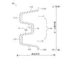
- FIG. 5 is a cross-sectional view taken along line AA of FIG. 4;
- FIG. 5 is a cross-sectional view taken along the line BB in FIG. 4;
- It is a perspective view of the plate-shaped member of 1st Embodiment. It is an enlarged view of the boundary part of a connection wall part and a side wall part.
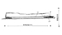
- FIG. 18 is a cross-sectional view showing a cross section perpendicular to a beam longitudinal direction of a front end portion (rear end portion) of the vehicle door impact beam of FIG.
- FIG. 17 It is sectional drawing which shows the cross section perpendicular
- FIG. 20 is a cross-sectional view showing a cross section perpendicular to the beam longitudinal direction of the front end portion (rear end portion) of the vehicle door impact beam of FIG. 19; It is the schematic of the center pillar which concerns on 2nd Embodiment.
- FIG. 22 is a cross-sectional view taken along the line AA of FIG.
- FIG. 22 is a cross-sectional view taken along the line BB in FIG. It is CC sectional drawing of FIG. It is a perspective view of the plate-shaped member of 2nd Embodiment.
- a door DR is attached to a frame of the vehicle V (a component forming a framework of a cabin) so as to be openable and closable.
- the vehicle door impact beam 10 according to the present embodiment is attached to the inside of the door DR.
- the door DR includes an outer panel OP and an inner panel IP as known.
- the vehicle door impact beam 10 is disposed between the outer panel OP and the inner panel IP.
- positions the door impact beam 10 for vehicles is small.
- the space (dimension in the vehicle width direction) in which the front end portion and the rear end portion of the vehicle door impact beam 10 are disposed is small.
- the present invention is applied to the vehicle door impact beam 10 attached to the left door DR of the vehicle V.
- the present invention relates to a vehicle door attached to another door It is also applicable to impact beams.
- the vehicle door impact beam 10 is formed in a long shape and extends from the rear end to the front end of the inner panel IP.
- the vehicle door impact beam 10 is fastened to the inner panel IP in an inclined state such that the front end side is positioned above the rear end side.
- FIGS. 5 and 6 are cross sections of a middle portion and an end portion (a front end portion and a rear end portion) in the longitudinal direction of the vehicle door impact beam 10, and a cross section perpendicular to the longitudinal direction of the vehicle door impact beam 10 It shows.
- the left and right direction on the sheet of FIG. 5 and FIG. 6 corresponds to the vehicle width direction.
- the inside of the vehicle door impact beam 10 is defined as the right.
- the outside of the vehicle door impact beam 10 is defined as the left.
- a direction perpendicular to the paper surface of FIGS. 5 and 6 is defined as a beam longitudinal direction.
- the beam longitudinal direction is orthogonal to the vehicle width direction.
- the vertical direction on the sheet of FIG. 5 and FIG. 6, that is, the direction orthogonal to the beam longitudinal direction and the vehicle width direction is defined as the beam width direction.
- one end side in the beam width direction of the door impact beam 10 for vehicles is defined as down.
- the other end side in the beam width direction of the vehicle door impact beam 10 is defined as the upper side.
- the cross section of the middle portion M1 in the beam longitudinal direction of the vehicle door impact beam 10 is an open cross section. That is, it is comprised so that the closed space may not be formed inside.
- the middle portion M1 has a groove-like portion 14 formed of groove-shaped first groove portions 11 and second groove portions 12 which extend in the beam longitudinal direction and are opened to the right. That is, the groove depth directions of the first groove portion 11 and the second groove portion 12 coincide with the vehicle width direction.
- the first groove 11 has a bottom wall 111 and side walls 112 and 113.
- the bottom wall portion 111 is formed in a plate shape extending in the beam longitudinal direction.
- the thickness direction of the bottom wall portion 111 coincides with the vehicle width direction.
- the width direction of the bottom wall portion 111 (the longitudinal direction of the bottom wall portion 111 and the direction perpendicular to the thickness direction) coincides with the beam width direction.
- the side wall portions 112 and 113 are each formed in a plate shape extending from the upper end portion and the lower end portion in the width direction of the bottom wall portion 111 to the right (vehicle compartment side) and each extending in the beam longitudinal direction.
- the thickness direction of the side wall portions 112 and 113 is slightly inclined with respect to the beam width direction.
- the side wall portion 112 has a flange portion 112F.
- the flange portion 112F is located at the right end of the side wall portion 112 and protrudes upward (outside of the groove (the space surrounded by the bottom wall portion 111 and the side wall portions 112 and 113)) and extends in the beam longitudinal direction There is.
- the second groove 12 extends parallel to the first groove 11 below the first groove 11. The positions in the vehicle width direction of the first groove portion 11 and the second groove portion 12 are the same.
- the second groove 12 has a bottom wall 121 and side walls 122 and 123 similar to the first groove 11.
- the side wall portion 122 has a flange portion 122F.
- the flange portion 122F is located at the right end of the side wall portion 122 and protrudes downward (outside the groove (the space surrounded by the bottom wall portion 121 and the side wall portions 122 and 123)) and extends in the beam longitudinal direction There is.
- connection wall portion 13 is formed in a plate shape extending in the beam longitudinal direction.
- the plate thickness direction of the connection wall portion 13 coincides with the vehicle width direction.
- the side wall 113, the side wall 123, and the connection wall 13 form a groove G which extends in the longitudinal direction of the vehicle door impact beam 10 and is open to the left.
- the cross section perpendicular to the longitudinal direction of the intermediate portion M1 is constant regardless of the cutting position, as shown in FIG.
- the dimension in the beam longitudinal direction of the intermediate portion M1 is, for example, 600 mm.
- the plate thicknesses of the bottom wall portions 111 and 121 and the connection wall portion 13 are larger than those of the side wall portions 112, 113, 122 and 123.
- the plate thickness of the bottom wall portions 111 and 121 and the connection wall portion 13 is, for example, 4.5 mm.
- board thickness of side wall part 112, 113, 122, 123 is 2.5 mm, for example.
- the front end F1 and the rear end R1 in the beam longitudinal direction of the vehicle door impact beam 10 are formed in a plate shape. Since the configurations of the front end F1 and the rear end R1 are the same, hereinafter, the configuration of the front end F1 will be described, and the description of the rear end R1 will be omitted.
- the front end F1 includes plate-like portions 111a, 112a, 113a, 121a, 122a, 123a, and 13a extending in the beam longitudinal direction.
- the thickness direction of these plate-like parts coincides with the vehicle width direction.
- the lower end of the plate-like portion 112a is connected to the upper end in the beam width direction of the plate-like portion 111a, and the upper end of the plate-like portion 113a is connected to the lower end of the plate-like portion 111a.
- the lower end of the plate-like portion 123a is connected to the upper end in the beam width direction of the plate-like portion 121a, and the upper end of the plate-like portion 122a is connected to the lower end of the plate-like portion 121a.
- the plate-like portion 113a is connected to the upper end of the plate-like portion 13a, and the upper end of the plate-like portion 123a is connected to the lower end of the plate-like portion 13a.
- the right side of each plate-like part is located in the same plane.
- the plate-like portion 13a is formed with a through hole (not shown) penetrating in the vehicle width direction.
- the cross section perpendicular to the longitudinal direction of the front end F1 is constant regardless of the cutting position, as shown in FIG.
- the dimension of the front end F1 in the beam longitudinal direction is, for example, 100 mm.
- the plate thickness of the plate-like parts 111a, 121a, 13a is larger than that of the plate-like parts 112a, 113a, 122a, 123a.
- the plate thickness of the plate-like portions 111a, 121a, 13a is, for example, 4.5 mm.
- the plate thickness of the plate-like portions 112a, 113a, 122a, 123a is, for example, 2.5 mm.
- connection portion CR1 As shown in FIG. 3, in the vehicle door impact beam 10, the middle portion M1 and the front end portion F1 are connected via the connection portion CF1, and the middle portion M1 and the rear end portion R1 are connected via the connection portion CR1. It is done.
- the configuration of the connection portion CR1 is the same as the configuration of the connection portion CF1, and hence the configuration of the connection portion CF1 will be described below, and the description of the connection portion CR1 will be omitted.
- the cross-sectional shape perpendicular to the beam longitudinal direction gradually changes from the front end to the rear end of the connection portion CF1.
- the cross-sectional shape of the front end of the connection part CF1 matches the cross-sectional shape of the front end F1
- the cross-sectional shape of the rear end of the connection part CF1 matches the cross-sectional shape of the middle part M1. That is, the plate-like portion 111 a is connected to the bottom wall portion 111.
- the plate-like portion 112 a is connected to the side wall portion 112.
- the plate-like portion 113 a is connected to the side wall portion 113.
- the plate-like portion 121 a is connected to the bottom wall portion 121.
- the plate-like portion 122 a is connected to the side wall portion 122.
- the plate-like portion 123 a is connected to the side wall portion 123.
- the plate-like portion 13 a is connected to the connection wall portion 13.
- a metal material for example, an aluminum alloy material
- extrusion processing step is extrusion-processed to manufacture a strip-shaped plate-like member BM1 (extrusion processing step).
- the shape of the cross section perpendicular to the longitudinal direction of the plate member BM1 is as shown in FIG. That is, the shape of the cross section perpendicular to the longitudinal direction of the plate-like member BM1 matches the shape of the cross section perpendicular to the longitudinal direction of the front end F1 and the rear end R1.
- the plate-like member BM1 includes plate-like portions 111a, 112a, 113a, 121a, 122a, 123a, and 13a.
- the plate-like portions 111a and 121a correspond to a first plate-like portion of the present invention
- the plate-like portions 112a, 113a, 122a and 123a correspond to a second plate-like portion of the present invention. That is, the plate thickness of the plate-like parts 112a, 113a, 122a, 123a is smaller than that of the plate-like parts 111a, 121a.
- plate-like-part 111a, 121a, 112a, 113a, 122a, 123a is formed in strip shape.
- plate-like-part 112a, 113a is extended along the edge part in the width direction of the plate-like-part 111a.
- the plate-like parts 122a and 123a are extended along the end in the width direction of the plate-like part 121a.
- an intermediate portion in the longitudinal direction of the plate-like member BM1 heated by the die quenching method is formed so that the shape of the cross section perpendicular to the longitudinal direction exhibits the shape shown in FIG.
- quenching and quenching pressing process. That is, the plate-like parts 111a and 121a of the plate-like member BM1 face the outer panel OP of the door DR, and the plate-like parts 112a, 113a, 122a and 123a are inner from the end in the width direction of the plate-like parts 111a and 121a.
- the plate-like member BM1 is pressed so as to extend toward the panel IP. Then, the through holes are formed in the plate-like portion 13a.
- the vehicle door impact beam 10 is formed.
- a bolt is inserted into the through hole from the right side (inside the vehicle interior) of the inner panel IP, and the tip of the bolt is fastened to the nut, whereby the vehicle door impact beam 10 is fixed to the left side of the inner panel IP.
- Ru When the vehicle door impact beam 10 is fixed to the inner panel IP, both ends in the beam longitudinal direction abut the inner panel IP, but the middle portion in the beam longitudinal direction is separated from the inner panel IP .
- the vehicle door impact beam 10 can be used without using a bracket even if the internal space at the end of the door DR is narrow.
- the impact beam 10 can be attached directly to the door DR.
- plate-shaped member BM1 does not have a closed space, extrusion speed can be made quicker than the conventional cylindrical door impact beam for vehicles. That is, it is easier to push the material out of the mold than in the case of manufacturing a tubular member such as the vehicle door impact beam of Patent Documents 1 and 2 described above. Therefore, it is possible to use a material of higher strength than before.
- an aluminum alloy material having a tensile strength of about 400 MPa is employed.
- an aluminum alloy material having a tensile strength of about 500 MPa can be employed.
- the side walls having a small influence on the bending rigidity of the first wall portion 11 and the bottom wall portions 111 and 121 of the first groove portion 12 and the second groove 12 having a large influence on the bending rigidity. It was thicker than the parts 112, 113, 122, 123. Thus, the bending rigidity can be kept high, and the weight of the vehicle door impact beam 10 can be reduced.
- the vehicle door impact beam 20 has a middle portion M2 in the longitudinal direction formed in a groove shape, and a front end portion F2 and a rear end portion R2 are formed in a flat plate shape.
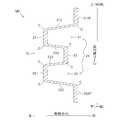
- the shape of the middle portion M2 of the vehicle door impact beam 20 is substantially the same as the shape of the middle portion M1 of the vehicle door impact beam 10, as shown in FIG. That is, the vehicle door impact beam 20 has a groove 24 formed of the first groove 21 and the second groove 22. The first groove 21 and the second groove 22 are connected by the connection wall 23.
- chamfers C are respectively formed on the upper end and the lower end of the bottom wall portion 211, the bottom wall portion 221, and the connection wall portion 23.
- the plate thickness of the flange portion 212F and the flange portion 222F is the same as the plate thickness of the bottom wall portion 211, the bottom wall portion 221 and the connection wall portion 23.
- a chamfered portion C is formed on the lower end of the flange portion 212F and the upper end of the flange portion 222F.
- the shapes of the front end F2 and the rear end R2 are as shown in FIG.
- the front end portion F2 and the rear end portion R2 include plate-like portions 211a, 212a, 213a, 212Fa, 221a, 222a, 223a, 222Fa, and 23a.
- the plate-like portions 211a and 221a correspond to a first plate-like portion of the present invention
- the plate-like portions 212a, 213a, 222a and 223a correspond to a second plate-like portion of the present invention. That is, the plate thickness of the plate-like portions 212a, 213a, 222a, 223a is smaller than that of the plate-like portions 211a, 221a.
- each plate-like part is formed in strip shape.
- the plate-like portions 212a and 213a are extended along the end in the width direction of the plate-like portion 211a.
- the plate-like portions 222a and 223a are extended along the end in the width direction of the plate-like portion 221a.
- the plate-like portion 212Fa and the plate-like portion 222Fa are respectively provided at both ends in the width direction of the plate-like member BM2.
- the plate thicknesses of the plate-like portion 212Fa and the plate-like portion 222Fa are the same as the plate thicknesses of the plate-like portions 211a and 221a.
- a side surface (right surface) of one of the plate-like parts 212a and 213a that constitutes one side surface (right surface) of the plate-like member BM2 is one side surface of the plate-like part 211a. It is continuous with the side that constitutes one side (right side) of That is, the right surfaces of the plate-like portions 211a, 212a and 213a are located in the same plane. In other words, no step is formed on the right surface of the plate-like member BM2 and in the portion formed of the right surfaces of the plate-like portions 211a, 212a, and 213a.
- the left surface of the plate-like portions 23a, 213a and 223a is located in the same plane. . Moreover, the left surface of plate-like-part 212a, 212Fa is located in the same plane. The left surfaces of the plate-like portions 222a and 222Fa are located in the same plane.
- chamfered portions C are formed at the upper left corner and the lower left corner of the plate-like portions 211a and 221a. Further, a chamfered portion C is formed at the upper right corner and the lower right corner of the plate-like portion 23a. Further, a chamfered portion C is formed on the lower right corner of the plate-like portion 212Fa and the upper right corner of the plate-like portion 222Fa.
- a metal material for example, an aluminum alloy material
- a strip-shaped plate-like member BM2 extruded to manufacture a strip-shaped plate-like member BM2 (extrusion processing step).
- the shape of the cross section perpendicular to the longitudinal direction of the plate-like member BM2 is as shown in FIG.
- the intermediate portion in the longitudinal direction of the heated plate-like member BM2 is made such that the shape of the cross section perpendicular to the longitudinal direction exhibits the shape shown in FIG.
- quenching and quenching pressing process. That is, the plate-like parts 211a and 221a of the plate-like member BM2 face the outer panel OP of the door DR, and the plate-like parts 212a, 213a, 222a and 223a are inner from the end in the width direction of the plate-like parts 211a and 221a.
- the plate-like member BM2 is pressed so as to extend toward the panel IP so that the plate-like portions 212Fa and 222Fa face the inner panel IP of the door DR (see FIG. 13). That is, the plate-like member BM2 is pressed so that the right side of the plate-like portion 211a and the right side of the plate-like portions 212a and 213a constitute the inner side surface of the first groove portion 21. The plate-like member BM2 is pressed so that the right side of the plate-like portion 221a and the right side of the plate-like portions 222a and 223a form the inner side of the second groove 22. Then, the through holes are formed in the plate-like portion 23a. Thus, the vehicle door impact beam 20 is formed.
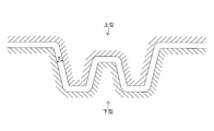
- a mold constituted of an upper mold and a lower mold is used.
- the gap t between the upper and lower dies that is, the portion for forming the intermediate portion M2 of the vehicle door impact beam 20
- the gap t between the upper and lower dies has a plate thickness such as that of the plate-like portions 211a and 221a Is the same as That is, a mold similar to the mold used when molding the vehicle door impact beam having the same plate thickness of the bottom wall portion and the side wall portion is used. Therefore, as shown in FIG. 13, when forming the middle portion M2 of the vehicle door impact beam 20, the side wall portions 212, 213, 222, 223 do not contact the mold in a state where the mold is closed. .
- the other part of the vehicle door impact beam 20 (the boundary between the connection wall 23 and the side wall 213, the boundary between the connection wall 23 and the side wall 223, the boundary between the side wall 212 and the flange 212F, and the side wall Also at the boundary between the portion 222 and the flange portion 222F), there is no portion that is greatly bent. Therefore, the strength of the vehicle door impact beam 20 can be higher than that of the vehicle door impact beam 10.
- the present invention is not limited to the above embodiment, and various modifications can be made without departing from the object of the present invention.
- the cross-sectional shape of the plate-like member BM2 is not limited to the shape of FIG.
- the right side of the plate-like portions 211a, 221a, 212Fa, 222Fa is located in the same plane, and the left side of the plate-like portions 211a, 221a, 212Fa, 222Fa is located in the same plane. It is good also as member BM2A.
- the plate-like portions 212a, 213a, 222a, 223a are inclined with respect to the width direction of the plate-like member BM2A.
- the right surface of the plate portion 212a is continuous with the right surface of the plate portion 211a, and the left surface of the plate portion 212a is continuous with the left surface of the plate portion 212Fa.
- the right surface of the plate portion 213a is continuous with the right surface of the plate portion 211a, and the left surface of the plate portion 213a is continuous with the left surface of the plate portion 23a.
- the left surface of the plate-like portion 223a is continuous with the left surface of the plate-like portion 23a, and the right surface of the plate-like portion 223a is continuous with the right surface of the plate-like portion 221a.
- the right surface of the plate portion 222a is continuous with the right surface of the plate portion 221a, and the left surface of the plate portion 222a is continuous with the left surface of the plate portion 222Fa.
- the cross-sectional shape of the intermediate part M2 is not limited to the shape of FIG.
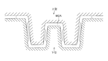
- an intermediate portion M2A as shown in FIG. 15 may be used.
- the middle portion M2A is formed by bending the end portions of the plate-like portions 211a, 221a, 23a, 212Fa, and 222Fa in the plate-like member BM2A, as shown in FIG. Also in this case, it is possible to divert the mold used when forming the vehicle door impact beam having the same plate thickness of the bottom wall portion and the side wall portion.
- middle part M3 may be constituted from one groove part opened towards the inner panel IP side.
- the middle portion M3 has a bottom wall portion 341, side wall portions 342 and 343, and flange portions 342F and 343F.
- the front end F3 (rear end R3) has plate-like portions 341a, 342a, 343a.
- a plate-like member BM3 having a cross-sectional shape shown in FIG.
- the plate-like portion 341a corresponds to a first plate-like portion of the present invention
- the plate-like portions 342a and 343a correspond to a second plate-like portion of the present invention.
- a vehicle door impact beam having an intermediate portion M4 as shown in FIG. 19 and having a front end F4 and a rear end R4 as shown in FIG.
- the middle portion M4 has a bottom wall 451, side walls 452, 453, and flanges 452F, 453F.
- the front end F4 (rear end R4) has plate-like portions 451a, 452a, 453a.
- a plate-like member BM4 having the cross-sectional shape shown in FIG. 20 is manufactured using an extrusion molding method, and the intermediate portion in the longitudinal direction of the plate-like member BM4 exhibits a shape as shown in FIG. Just press it as you like.
- the plate-like portion 451a corresponds to a first plate-like portion of the present invention
- the plate-like portions 452a and 453a correspond to a second plate-like portion of the present invention.
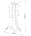
- the center pillar 50 which concerns on 2nd Embodiment of this invention is demonstrated.
- the center pillar 50 is extended in the vehicle height direction at the side surface of the vehicle.
- the center pillar 50 is disposed at a central portion in the vehicle longitudinal direction of an opening (alighting / unloading opening) formed in a side surface of the vehicle.
- an opening an opening (alighting / unloading opening) formed in a side surface of the vehicle.
- the center pillar 50 provided on the left side of the vehicle will be described, but the present invention is also applicable to a center pillar provided on the right side of the vehicle.
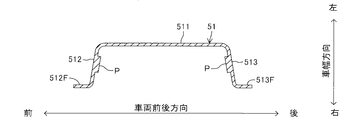
- the center pillar 50 has a groove 51 extending in the height direction of the vehicle and open to the right (inside of the vehicle compartment). That is, the grooved portion 51 has a bottom wall portion 511, a side wall portion 512, and a side wall portion 513.
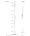
- the bottom wall portion 511 is formed in a plate shape substantially perpendicular to the vehicle width direction. Strictly speaking, the bottom wall portion 511 is gently curved such that the upper end thereof is positioned slightly to the right of the lower end. Further, the dimension in the longitudinal direction of the vehicle gradually increases as it goes downward from the upper end portion of the bottom wall portion 511. However, at the lower end portion (portion extending about 1 ⁇ 4 of the total length) of the bottom wall portion 511, the dimension in the vehicle longitudinal direction is rapidly (exponentially) increased.
- the side wall portion 512 is extended rightward from the front end portion of the bottom wall portion 511. Further, the side wall portion 513 is extended rightward from the rear end portion of the bottom wall portion 511.
- the side wall portion 512 and the side wall portion 513 are respectively formed with a flange portion 512F and a flange portion 513F.
- the flange portion 512F is extended forward from the right end portion of the side wall portion 512. Further, the flange portion 513F is extended rearward from the right end portion of the side wall portion 513.
- an upper connection portion 52 connected to a member (roof side rail) that constitutes the frame of the roof of the vehicle is formed.
- the upper connection portion 52 is formed in a plate shape extending in the vehicle longitudinal direction and substantially parallel to the upper end portion of the bottom wall portion 511.
- the lower end portion of the groove-shaped portion 51 is formed with a lower connection portion 53 connected to a member (side sill) that constitutes the lower edge portion of the entrance of the vehicle.
- the lower connection portion 53 is formed in a plate shape extending in the vehicle longitudinal direction and substantially parallel to the lower end portion of the bottom wall portion 511.
- protrusions P and P extending in parallel to the longitudinal direction of the groove 51 are formed on the inner side surface of the groove 51.
- the protruding portions P, P are located on the inner side surfaces of the side wall portion 512 and the side wall portion 513, respectively.
- the protruding portions P, P are the boundary portion between the bottom wall portion 511 and the side wall portion 512, and the bottom wall portion 511 It is located at the boundary with the side wall 513, respectively.
- the protruding portions P, P are respectively positioned on the inner side surface of the bottom wall portion 511.
- the center pillar 50 is also formed by pressing a plate-like member manufactured using an extrusion molding method, similarly to the door impact beams 10 and 20 for a vehicle.
- a metal material for example, an aluminum alloy material
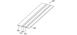
- the extrusion direction of the plate-like member BP corresponds to the longitudinal direction (vehicle height direction) of the center pillar 50.
- the plate-like member BP includes plate-like portions B1, B2, B3 and a pair of plate-like portions Pa, Pa.
- Plate-like parts Pa and Pa correspond to the 1st plate-like part of the present invention
- plate-like parts B1, B2, and B3 correspond to the 2nd plate-like part of the present invention. That is, the plate thicknesses of the plate-like portions B1, B2, B3 are smaller than the plate-like portions Pa, Pa.
- the plate-like portions B1, B2 and B3 and the pair of plate-like portions Pa and Pa are formed in a band shape.
- the plate-like portions B1, B2, and B3 are separated from each other in the width direction of the plate-like member BP (the direction perpendicular to the extrusion direction and the plate thickness direction).
- One plate-like portion Pa is formed between the plate-like portion B1 and the plate-like portion B2, and the other plate-like portion Pa is formed between the plate-like portion B1 and the plate-like portion B3.
- the dimensions in the width direction of the plate-like parts Pa, Pa are smaller than the dimensions in the width direction of the plate-like parts B1, B2, B3.
- a portion of the plate-like portion B2 and the plate-like portion B3 of the plate-like member BP is trimmed Do (trimming process).
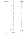
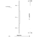
- the shape of the cross section perpendicular to the longitudinal direction of the plate-like member BP heated by the die quenching method exhibits the shapes shown in FIGS. 22A, 22B, and 22C.
- the grooved portion 51 is formed as follows. At an intermediate portion in the longitudinal direction of the plate member BP, an intermediate portion in the width direction of the plate portions Pa, Pa is bent along the longitudinal direction. At one end (upper end) in the longitudinal direction of the plate-like member BP, a portion of the plate-like portion B1 which is located slightly inside as viewed from the plate-like portions Pa, Pa is bent.
- the grooved portion 51 is formed. That is, the bent portion corresponds to the ridge line of the grooved portion 51.
- the plate-like parts Pa, Pa correspond to the protruding parts P, P.
- the center pillar 50 configured as described above, the same effect as that of the first embodiment can be obtained.
- a plate at the boundary between the bottom wall 511 and the side wall 512 at the middle in the longitudinal direction and at the boundary between the bottom wall 511 and the side wall 513 which greatly affects the bending rigidity.
- the thickness was made thicker than other parts that have less influence on the flexural rigidity.
- the bending rigidity can be kept high, and the center pillar 50 can be reduced in weight.
- the center pillar 50 is integrally formed. Therefore, not only the number of parts can be reduced but also the number of assembling steps can be reduced as compared with the conventional center pillar in which rigidity is enhanced by combining a plurality of parts.
- the protruding portions P, P are offset from the ridge line of the groove-shaped portion 51. Therefore, in these parts, the protrusions P and P do not contribute much to the improvement of the rigidity of the center pillar 50. Therefore, in the pressing process, the plate-like portions Pa, Pa at the upper end portion and the lower end portion of the center pillar 50 may be crushed.
- only the middle portion in the longitudinal direction of the center pillar 50 may be formed of the plate-like member BP, and the upper end and the lower end may be formed of plate-like members having a constant plate thickness.
- the plate thickness of the portion corresponding to the ridge line of the bottom wall portion 511 and the grooved portion 51 may be increased as a whole.
- the die-quenching method hot pressing method
- a cold pressing method a warm pressing method, or the like may be used.
- the present invention is also applicable to a vehicle frame member different from the above embodiment.
- the present invention is applicable to front side members, roof reinforcement, and the like.
- the plate thickness of the surface perpendicular to the direction of the external force acting on the member or the bent portion may be made larger than that of the other portion.
Landscapes
- Engineering & Computer Science (AREA)
- Mechanical Engineering (AREA)
- Chemical & Material Sciences (AREA)
- Combustion & Propulsion (AREA)
- Transportation (AREA)
- Architecture (AREA)
- Structural Engineering (AREA)
- Body Structure For Vehicles (AREA)
- Extrusion Of Metal (AREA)
Abstract
Description
前記金型を閉じた状態における前記上型と前記下型との間の隙間(t)が前記第1板状部の板厚に等しく設定されているとよい。
以下、本発明の第1実施形態に係る車両用ドアインパクトビーム10について説明する。まず、車両用ドアインパクトビーム10が取り付けられる車両Vの概略について説明する。図1に示すように、車両Vのフレーム(車室の骨格を構成する部品)には、ドアDRが開閉可能に取り付けられている。このドアDRの内部に本実施形態に係る車両用ドアインパクトビーム10が取り付けられる。ドアDRは、公知のようにアウターパネルOPとインナーパネルIPとを備えている。車両用ドアインパクトビーム10はアウターパネルOPとインナーパネルIPとの間に配置される。ドアDRの内部には、車両用ドアインパクトビーム10の他に、ドアガラス、ドアガラスを昇降させる装置などが配置される。よって、図2に示すように、車両用ドアインパクトビーム10を配置する空間が小さい。とくに、車両用ドアインパクトビーム10の前端部及び後端部が配置される空間(車幅方向の寸法)が小さい。なお、本実施形態では、本発明が、車両Vの左側のドアDRに取り付けられる車両用ドアインパクトビーム10に適用された例について説明するが、本発明は、他のドアに取り付けられる車両用ドアインパクトビームにも適用可能である。
つぎに、本発明の第2実施形態に係るセンターピラー50について説明する。センターピラー50は、車両の側面部にて、車両高さ方向に延設されている。センターピラー50は、車両の側面部に形成された開口部(乗降口)の車両前後方向における中央部に配置されている。本実施形態では、車両の左側面部に設けられるセンターピラー50について説明するが、本発明は、車両の右側面部に設けられるセンターピラーにも適用可能である。
Claims (5)
- 所定の方向に延びる1つ又は複数の溝状部を有する車両用骨格部材の製造方法であって、
前記所定の方向に延びる帯状の1つ又は複数の第1板状部と、前記第1板状部の幅方向における端部に沿って前記所定の方向にそれぞれ延びる帯状の第2板状部であって、前記第1板状部よりも板厚の小さな第2板状部とを有する板状部材を、押出成形法を用いて製造する押出加工工程と、
前記溝状部の底壁部の少なくとも一部が前記第1板状部から構成され、且つ前記溝状部の側壁部が前記第2板状部から構成されるように、前記板状部材をプレス加工するプレス加工工程と、
を含む、車両用骨格部材の製造方法。 - 請求項1に記載の車両用骨格部材の製造方法において、
前記第1板状部の両側に位置する2つの前記第2板状部の一方の側面であって、前記板状部材の一方の側面を構成する部分が、前記第1板状部の一方の側面であって、前記板状部材の一方の側面を構成する部分にそれぞれ連続し、
前記プレス加工工程は、前記第1板状部の一方の側面と、前記2つの第2板状部の一方の側面が前記溝状部の内側面を構成するように、前記板状部材をプレス加工する工程である、車両用骨格部材の製造方法。 - 請求項2に記載の車両用骨格部材の製造方法において、
前記板状部材の幅方向における両端部が前記第1板状部から構成され、
前記プレス加工工程は、上型と下型からなる金型を用いて前記板状部材を加工する工程であり、
前記金型を閉じた状態における前記上型と前記下型との間の隙間が前記第1板状部の板厚に等しく設定されている、車両用骨格部材の製造方法。 - 請求項1乃至3のうちのいずれか1つに記載の車両用骨格部材の製造方法において、
前記プレス加工工程は、少なくとも前記溝状部の底壁部と側壁部との境界部が前記第1板状部から構成され、且つ前記溝状部の側壁部が前記第2板状部から構成されるように、前記板状部材をプレス加工する工程である、車両用骨格部材の製造方法。 - 請求項1乃至4のうちのいずれか1つに記載の車両用骨格部材の製造方法において、
前記プレス加工工程は、ダイクエンチ工法を用いて、前記板状部材をプレス加工する工程である、車両用骨格部材の製造方法。
Priority Applications (3)
| Application Number | Priority Date | Filing Date | Title |
|---|---|---|---|
| JP2017563666A JP6545832B2 (ja) | 2016-01-29 | 2016-05-12 | 車両用骨格部材の製造方法 |
| US16/072,735 US20190030586A1 (en) | 2016-01-29 | 2016-05-12 | Method of manufacturing skeleton member for vehicle |
| MX2018008820A MX2018008820A (es) | 2016-01-29 | 2016-05-12 | Metodo de fabricacion de miembro de armazon para vehiculo. |
Applications Claiming Priority (2)
| Application Number | Priority Date | Filing Date | Title |
|---|---|---|---|
| JP2016015020 | 2016-01-29 | ||
| JP2016-015020 | 2016-01-29 |
Publications (1)
| Publication Number | Publication Date |
|---|---|
| WO2017130429A1 true WO2017130429A1 (ja) | 2017-08-03 |
Family
ID=59397730
Family Applications (1)
| Application Number | Title | Priority Date | Filing Date |
|---|---|---|---|
| PCT/JP2016/064161 Ceased WO2017130429A1 (ja) | 2016-01-29 | 2016-05-12 | 車両用骨格部材の製造方法 |
Country Status (4)
| Country | Link |
|---|---|
| US (1) | US20190030586A1 (ja) |
| JP (1) | JP6545832B2 (ja) |
| MX (1) | MX2018008820A (ja) |
| WO (1) | WO2017130429A1 (ja) |
Cited By (3)
| Publication number | Priority date | Publication date | Assignee | Title |
|---|---|---|---|---|
| JP2019166855A (ja) * | 2018-03-22 | 2019-10-03 | 日本製鉄株式会社 | 車両用構造部材及び車両 |
| JP2020125022A (ja) * | 2019-02-05 | 2020-08-20 | フタバ産業株式会社 | プレス成形品 |
| JP2021075258A (ja) * | 2019-05-16 | 2021-05-20 | アイシン精機株式会社 | ドアビーム |
Families Citing this family (3)
| Publication number | Priority date | Publication date | Assignee | Title |
|---|---|---|---|---|
| KR20200001257A (ko) * | 2018-06-27 | 2020-01-06 | 현대자동차주식회사 | 도어 임팩트 빔 |
| EP3856427B1 (en) * | 2018-09-26 | 2023-04-26 | Hydro Extruded Solutions AS | Clamping strap |
| US11642712B1 (en) * | 2022-02-24 | 2023-05-09 | GM Global Technology Operations LLC | Method of manufacturing vehicle body structure component to include reinforced regions |
Citations (4)
| Publication number | Priority date | Publication date | Assignee | Title |
|---|---|---|---|---|
| US5232261A (en) * | 1992-06-04 | 1993-08-03 | Nhk Spring Co., Ltd. | Door impact beam for an automobile |
| JP2007076433A (ja) * | 2005-09-13 | 2007-03-29 | Kobe Steel Ltd | 自動車のドアビーム |
| JP2009196488A (ja) * | 2008-02-21 | 2009-09-03 | Aisin Takaoka Ltd | 車両用衝突補強材 |
| JP2010195187A (ja) * | 2009-02-25 | 2010-09-09 | Aisin Takaoka Ltd | 車両用衝突補強材 |
-
2016
- 2016-05-12 JP JP2017563666A patent/JP6545832B2/ja not_active Expired - Fee Related
- 2016-05-12 MX MX2018008820A patent/MX2018008820A/es unknown
- 2016-05-12 US US16/072,735 patent/US20190030586A1/en not_active Abandoned
- 2016-05-12 WO PCT/JP2016/064161 patent/WO2017130429A1/ja not_active Ceased
Patent Citations (4)
| Publication number | Priority date | Publication date | Assignee | Title |
|---|---|---|---|---|
| US5232261A (en) * | 1992-06-04 | 1993-08-03 | Nhk Spring Co., Ltd. | Door impact beam for an automobile |
| JP2007076433A (ja) * | 2005-09-13 | 2007-03-29 | Kobe Steel Ltd | 自動車のドアビーム |
| JP2009196488A (ja) * | 2008-02-21 | 2009-09-03 | Aisin Takaoka Ltd | 車両用衝突補強材 |
| JP2010195187A (ja) * | 2009-02-25 | 2010-09-09 | Aisin Takaoka Ltd | 車両用衝突補強材 |
Cited By (5)
| Publication number | Priority date | Publication date | Assignee | Title |
|---|---|---|---|---|
| JP2019166855A (ja) * | 2018-03-22 | 2019-10-03 | 日本製鉄株式会社 | 車両用構造部材及び車両 |
| JP7264597B2 (ja) | 2018-03-22 | 2023-04-25 | 日本製鉄株式会社 | 車両用構造部材及び車両 |
| JP2020125022A (ja) * | 2019-02-05 | 2020-08-20 | フタバ産業株式会社 | プレス成形品 |
| JP7244287B2 (ja) | 2019-02-05 | 2023-03-22 | フタバ産業株式会社 | プレス成形品 |
| JP2021075258A (ja) * | 2019-05-16 | 2021-05-20 | アイシン精機株式会社 | ドアビーム |
Also Published As
| Publication number | Publication date |
|---|---|
| US20190030586A1 (en) | 2019-01-31 |
| JP6545832B2 (ja) | 2019-07-17 |
| JPWO2017130429A1 (ja) | 2018-11-22 |
| MX2018008820A (es) | 2019-02-20 |
Similar Documents
| Publication | Publication Date | Title |
|---|---|---|
| JP6545832B2 (ja) | 車両用骨格部材の製造方法 | |
| JP5927187B2 (ja) | 自動車の中柱補強体 | |
| US10239388B2 (en) | Impact beam and method for producing an impact beam | |
| CN106994490B (zh) | 用于由挤出的轻金属型材制造机动车构件的方法和设备 | |
| CN108136479A (zh) | 用于制造机动车构件的方法 | |
| JP6489152B2 (ja) | 車両用フレーム部材 | |
| US10960927B2 (en) | Longitudinal beam and method for the production thereof | |
| EP2878495A1 (en) | Shock absorbing member | |
| CN108778806A (zh) | 门内面板及门内面板制造方法 | |
| CN110395093A (zh) | 门梁 | |
| CN207579811U (zh) | 保险杠加强件 | |
| JP2015147490A (ja) | アルミニウム合金押出形材からなるドアビーム | |
| JP4932688B2 (ja) | 自動車車体用ルーフ補強材 | |
| US11192160B2 (en) | Structural member | |
| CN109789899B (zh) | 车辆用结构体 | |
| CN206012292U (zh) | 车辆用门防撞梁 | |
| US9878603B2 (en) | Vehicle door impact beam | |
| US20080001432A1 (en) | Beam, and Method for Making Such Beam | |
| JP5357786B2 (ja) | 構造部材用アルミニウム合金押出形材 | |
| JP7084159B2 (ja) | 車両のドアビーム | |
| JP4611158B2 (ja) | 自動車のドアビーム | |
| JP3873978B2 (ja) | 車体骨格部材 | |
| JP4783761B2 (ja) | 車両用フロントサイドフレームの製造方法。 | |
| JP6551458B2 (ja) | 車両用フレーム部材 | |
| JP6551459B2 (ja) | 車両用フレーム部材 |
Legal Events
| Date | Code | Title | Description |
|---|---|---|---|
| 121 | Ep: the epo has been informed by wipo that ep was designated in this application |
Ref document number: 16888015 Country of ref document: EP Kind code of ref document: A1 |
|
| ENP | Entry into the national phase |
Ref document number: 2017563666 Country of ref document: JP Kind code of ref document: A |
|
| WWE | Wipo information: entry into national phase |
Ref document number: MX/A/2018/008820 Country of ref document: MX |
|
| NENP | Non-entry into the national phase |
Ref country code: DE |
|
| 122 | Ep: pct application non-entry in european phase |
Ref document number: 16888015 Country of ref document: EP Kind code of ref document: A1 |