WO2017126196A1 - 内視鏡 - Google Patents
内視鏡 Download PDFInfo
- Publication number
- WO2017126196A1 WO2017126196A1 PCT/JP2016/083058 JP2016083058W WO2017126196A1 WO 2017126196 A1 WO2017126196 A1 WO 2017126196A1 JP 2016083058 W JP2016083058 W JP 2016083058W WO 2017126196 A1 WO2017126196 A1 WO 2017126196A1
- Authority
- WO
- WIPO (PCT)
- Prior art keywords
- observation window
- endoscope
- cleaning
- cleaning nozzle
- liquid
- Prior art date
Links
Images


Classifications
-
- G—PHYSICS
- G02—OPTICS
- G02B—OPTICAL ELEMENTS, SYSTEMS OR APPARATUS
- G02B23/00—Telescopes, e.g. binoculars; Periscopes; Instruments for viewing the inside of hollow bodies; Viewfinders; Optical aiming or sighting devices
- G02B23/24—Instruments or systems for viewing the inside of hollow bodies, e.g. fibrescopes
-
- A—HUMAN NECESSITIES
- A61—MEDICAL OR VETERINARY SCIENCE; HYGIENE
- A61B—DIAGNOSIS; SURGERY; IDENTIFICATION
- A61B1/00—Instruments for performing medical examinations of the interior of cavities or tubes of the body by visual or photographical inspection, e.g. endoscopes; Illuminating arrangements therefor
- A61B1/00064—Constructional details of the endoscope body
- A61B1/00071—Insertion part of the endoscope body
- A61B1/0008—Insertion part of the endoscope body characterised by distal tip features
- A61B1/00091—Nozzles
-
- A—HUMAN NECESSITIES
- A61—MEDICAL OR VETERINARY SCIENCE; HYGIENE
- A61B—DIAGNOSIS; SURGERY; IDENTIFICATION
- A61B1/00—Instruments for performing medical examinations of the interior of cavities or tubes of the body by visual or photographical inspection, e.g. endoscopes; Illuminating arrangements therefor
- A61B1/00064—Constructional details of the endoscope body
- A61B1/00071—Insertion part of the endoscope body
- A61B1/0008—Insertion part of the endoscope body characterised by distal tip features
- A61B1/00096—Optical elements
-
- A—HUMAN NECESSITIES
- A61—MEDICAL OR VETERINARY SCIENCE; HYGIENE
- A61B—DIAGNOSIS; SURGERY; IDENTIFICATION
- A61B1/00—Instruments for performing medical examinations of the interior of cavities or tubes of the body by visual or photographical inspection, e.g. endoscopes; Illuminating arrangements therefor
- A61B1/00163—Optical arrangements
- A61B1/00174—Optical arrangements characterised by the viewing angles
-
- A—HUMAN NECESSITIES
- A61—MEDICAL OR VETERINARY SCIENCE; HYGIENE
- A61B—DIAGNOSIS; SURGERY; IDENTIFICATION
- A61B1/00—Instruments for performing medical examinations of the interior of cavities or tubes of the body by visual or photographical inspection, e.g. endoscopes; Illuminating arrangements therefor
- A61B1/12—Instruments for performing medical examinations of the interior of cavities or tubes of the body by visual or photographical inspection, e.g. endoscopes; Illuminating arrangements therefor with cooling or rinsing arrangements
- A61B1/126—Instruments for performing medical examinations of the interior of cavities or tubes of the body by visual or photographical inspection, e.g. endoscopes; Illuminating arrangements therefor with cooling or rinsing arrangements provided with means for cleaning in-use
-
- G—PHYSICS
- G02—OPTICS
- G02B—OPTICAL ELEMENTS, SYSTEMS OR APPARATUS
- G02B23/00—Telescopes, e.g. binoculars; Periscopes; Instruments for viewing the inside of hollow bodies; Viewfinders; Optical aiming or sighting devices
- G02B23/24—Instruments or systems for viewing the inside of hollow bodies, e.g. fibrescopes
- G02B23/2407—Optical details
- G02B23/2423—Optical details of the distal end
-
- G—PHYSICS
- G02—OPTICS
- G02B—OPTICAL ELEMENTS, SYSTEMS OR APPARATUS
- G02B23/00—Telescopes, e.g. binoculars; Periscopes; Instruments for viewing the inside of hollow bodies; Viewfinders; Optical aiming or sighting devices
- G02B23/24—Instruments or systems for viewing the inside of hollow bodies, e.g. fibrescopes
- G02B23/2476—Non-optical details, e.g. housings, mountings, supports
-
- G—PHYSICS
- G02—OPTICS
- G02B—OPTICAL ELEMENTS, SYSTEMS OR APPARATUS
- G02B27/00—Optical systems or apparatus not provided for by any of the groups G02B1/00 - G02B26/00, G02B30/00
- G02B27/0006—Optical systems or apparatus not provided for by any of the groups G02B1/00 - G02B26/00, G02B30/00 with means to keep optical surfaces clean, e.g. by preventing or removing dirt, stains, contamination, condensation
-
- A—HUMAN NECESSITIES
- A61—MEDICAL OR VETERINARY SCIENCE; HYGIENE
- A61B—DIAGNOSIS; SURGERY; IDENTIFICATION
- A61B1/00—Instruments for performing medical examinations of the interior of cavities or tubes of the body by visual or photographical inspection, e.g. endoscopes; Illuminating arrangements therefor
- A61B1/04—Instruments for performing medical examinations of the interior of cavities or tubes of the body by visual or photographical inspection, e.g. endoscopes; Illuminating arrangements therefor combined with photographic or television appliances
- A61B1/05—Instruments for performing medical examinations of the interior of cavities or tubes of the body by visual or photographical inspection, e.g. endoscopes; Illuminating arrangements therefor combined with photographic or television appliances characterised by the image sensor, e.g. camera, being in the distal end portion
Definitions
- the present invention relates to an endoscope, and more particularly to an endoscope having an observation window having a peripheral side surface formed in a cone shape.
- the endoscope has an elongated insertion portion, and an observation window is provided at the distal end portion of the insertion portion. Light incident through the observation window is photoelectrically converted to generate an endoscopic image that is a subject image, and the endoscopic image is displayed on a display device.
- endoscopes that can observe a subject with a wide field of view in order to prevent oversight of a lesion.
- a wide-angle endoscope having two or more fields such as a front field image and a side field image.
- Japanese Patent No. 558873 proposes a wide-angle endoscope having a front observation window for observing the front of the insertion portion and a side observation window having a frustoconical lens for observing the side. Yes. Also in the endoscope according to the proposal, a cleaning nozzle for cleaning each of the front observation window and the side observation window is provided in the vicinity of each observation window.
- the two cleaning nozzles for cleaning the side observation window of the lens unit having a circumferential side surface formed in a conical shape are arranged on the arcuate side from the direction orthogonal to the central axis of the frustoconical lens unit. It is provided in the front-end
- the cleaning liquid ejected from the cleaning nozzle is ejected in a direction orthogonal to the central axis of the truncated cone-shaped lens unit,
- the cleaning liquid is difficult to be transmitted over the entire circumference of the surface of the arc-shaped side observation window.
- the cleaning liquid sprayed in a direction perpendicular to the central axis of the truncated cone lens unit flows to the wide angle side which is the base end side of the truncated cone lens unit, but hardly flows to the narrow angle side which is the distal end side.
- an object of the present invention is to provide an endoscope having a cleaning nozzle that facilitates the transfer of cleaning liquid over the entire peripheral surface of an observation window having a peripheral side surface formed in a cone shape.
- An endoscope includes an elongated insertion portion, and a first observation window having a circumferential side surface that is tapered and formed in a conical shape around a side that intersects the longitudinal axis of the insertion portion. And a cleaning nozzle provided by inclining a liquid ejection direction for cleaning the peripheral side surface toward the tapered tip end side.
- Endoscope apparatus having an endoscope having a front observation window and a side observation window at the distal end of the insertion portion, and a cleaning mechanism for cleaning the front observation window and the side observation window, according to the embodiment of the present invention.
- It is a figure which shows the external appearance structure. It is a perspective view of the front-end
- FIG. 1 The position of the cleaning nozzle 28a provided by inclining the ejection directions FD1 and FD2 of the liquid LQ ejected from the openings 33a and 33b toward the tapered tip side of the lens unit 24 according to the embodiment of the present invention will be described.
- FIG. 1 The position of the cleaning nozzle 28a provided by inclining the ejection directions FD1 and FD2 of the liquid LQ ejected from the openings 33a and 33b toward the tapered tip side of the lens unit 24 according to the embodiment of the present invention will be described.
- FIG. 1 includes an endoscope having a front observation window and a side observation window at the distal end of an insertion portion, and a cleaning mechanism for cleaning the front observation window and the side observation window according to the embodiment of the present invention.
- FIG. 1 shows the external appearance structure of an endoscope apparatus.
- the endoscope apparatus according to the present embodiment is roughly composed of an endoscope 1 and an endoscope device 3 mounted on a movable trolley 2.
- a flexible endoscope will be described as an example.
- the present embodiment can be similarly applied to a rigid endoscope.
- the endoscope 1 has an elongated insertion portion 4 that is inserted into the body to be observed.
- the insertion portion 4 includes an elongated flexible tube 5 provided on the proximal end side, a bending portion 6 provided on the distal end side of the flexible tube 5, and a distal end portion 7 provided on the distal end side of the bending portion 6. including.
- the endoscope 1 includes an operation unit 8 provided with various buttons such as two bending operation knobs and release buttons for moving the bending unit 6 up and down and left and right, and extending from the operation unit 8.
- the extended universal cable 9 is further provided.
- the endoscopic device 3 includes a light source device 11 that generates illumination light to irradiate a site to be observed, a video processor 12 that performs predetermined image processing on the captured video signal, and a monitor that displays the video signal as an observation image. 13 and a keyboard 14 as an input unit for the user to input various commands and data.
- a bottle 15 for storing a cleaning liquid that is a liquid used for cleaning, for example, water or physiological saline, is detachably attached to the support of the trolley 2.
- an air supply pump unit (not shown) is disposed inside any one of the devices for the endoscope 3.
- the cleaning liquid is supplied to each cleaning nozzle via a liquid supply channel (not shown) when air from the air supply pump unit is supplied to the bottle 15.
- the shelf of the trolley 2 is provided with a suction unit 16 that sucks liquid or gas ejected from a cleaning nozzle described later in the body.
- the universal cable 9 is connected to the light source device 11 by a connector 17.
- the universal cable 9 includes, in addition to a light guide made of an optical fiber, a plurality of signal lines for transmitting video signals and the like, gas and liquid supply paths (air supply / liquid supply channels) and discharge paths made of tubes.
- a connector 17 connected to the endoscope device 3 side of the universal cable 9 is branched into a signal line, a tube, and a light guide, and is connected to respective components.
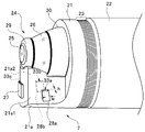
- FIG. 2 is a perspective view of the distal end portion 7 of the insertion portion 4 of the endoscope 1.
- FIG. 3 is a left side view of the distal end portion 7.
- the distal end portion 7 of the insertion portion 4 has a distal end body 21 made of resin.
- a rubber sheath member 22 covers the insertion portion 4.
- the distal end portion of the sheath member 22 is fixed to the distal end portion main body 21 by a thread winding portion 23.
- An adhesive is applied to the thread winding portion 23.
- a rectangular parallelepiped-shaped pedestal portion 21 a is formed on the distal end surface of the distal end portion main body 21 so as to protrude in the distal end direction that is the insertion direction of the insertion portion 4.
- a lens unit 24 is provided on the distal end surface of the distal end main body 21 so as to protrude adjacent to the pedestal portion 21a.
- the lens unit 24 has a substantially cylindrical shape and includes a front observation window 25 and a side observation window 26. That is, the pedestal portion 21 a is provided so as to protrude from the distal end portion of the insertion portion 4, and the lens unit 24 is provided adjacent to the pedestal portion 21 a so as to protrude from the distal end portion of the insertion portion 4.
- the front observation window 25 has a circular shape and is disposed on the front end surface of the lens unit 24.
- the side observation window 26 is provided on the peripheral side surface of the lens unit 24 in an arc shape along the circumferential direction, and is disposed on the rear side (that is, the base end side) of the front observation window 25.
- the lens unit 24 includes an imaging optical system of the endoscope 1, and the imaging optical system is disposed in front of an imaging element (not shown).
- the imaging optical system includes a plurality of lenses and lens groups to form a captured image, and each lens is supported by a lens frame (not shown).
- the side observation window 26 of the lens unit 24 has a truncated cone shape. Since the side observation window 26 has a truncated cone shape, the side observation window 26 has a tapered portion that is tapered. That is, the side observation window 26 is a part of the slope portion of the frustoconical lens, and has a tapered shape. Therefore, the side observation window 26 has an arc shape having a peripheral side surface formed in a cone shape.
- a front observation window 25 is provided at the tip of the side observation window 26.
- the side observation window 26 has a peripheral side surface formed in a conical shape with a taper that is tapered from the proximal end side toward the distal end side around the side that intersects the longitudinal axis of the insertion portion 4.
- the front observation window 25 has an optical axis along the longitudinal direction at the center of the arc shape of the side observation window 26.
- the front observation window 25 acquires the first subject image of the first region of the subject into which the insertion unit 4 is inserted, and the side observation window 26 is at least a part of the first region.
- a second subject image of the second region of the subject having a different is acquired.
- the first subject image acquired by the front observation window 25 is a subject image of a first region including the front of the insertion portion 4 along the longitudinal axis direction of the insertion portion 4, and is acquired by the side observation window 26.
- the second subject image is a subject image of the second region including the side of the insertion portion 4 that is a direction intersecting the longitudinal axis direction.
- the pedestal portion 21a is a tip structure in which the tip surface of the pedestal portion 21a has a height substantially the same as the front observation window 25 (height protruding forward).
- a cleaning nozzle 27 for cleaning the surface of the front observation window 25 is disposed in the vicinity of the front observation window 25 on the tip surface of the pedestal portion 21a. The cleaning nozzle 27 ejects liquid in a direction parallel to the distal end surface of the pedestal portion 21a.
- the two cleaning nozzles 28a and 28b for cleaning the surface of the side observation window 26 are arranged on the side surfaces of the pedestal 21a opposite to each other.
- the two cleaning nozzles 28 a and 28 b are provided in the vicinity of both ends of the arc-shaped side observation window 26.
- the distal end body 21 is also provided with an opening (not shown) of a treatment instrument insertion hole for inserting forceps and the like.
- An illumination window 29 having an annular shape is provided at the tip of the lens unit 24 so as to surround the front observation window 25.
- the illumination window 29 irradiates illumination light for illuminating the front of the distal end portion 7.
- an illumination window 30 having an arc shape is provided on the base end side of the side observation window 26.
- the illumination window 30 emits illumination light for illuminating mainly the side of the tip 7, that is, the area around the tip 7.
- a tip portion of a light guide (not shown) from which illumination light from the light source device 11 is emitted is disposed on the rear side of the illumination windows 29 and 30, a tip portion of a light guide (not shown) from which illumination light from the light source device 11 is emitted is disposed.
- the surface of the region between the illumination window 29 and the side observation window 26 is processed to prevent illumination light from the illumination window 29 from entering the side observation window 26.
- the surface of the region between the side observation window 26 and the illumination window 30 is also processed to prevent illumination light from the illumination window 30 from entering the side observation window 26.
- Two cleaning nozzles 28 a and 28 b are provided on the pedestal portion 21 a adjacent to the lens unit 24.
- the two cleaning nozzles 28a and 28b are respectively provided on two side surfaces 21a1 and 21a2 parallel to each other of the pedestal portion 21a.
- the cleaning nozzle 28a is disposed so as to protrude on the side surface 21a1, and is parallel to the side surface 21a1 from one end side of the arc-shaped side observation window 26 disposed on the outer peripheral surface of the lens unit 24. Spout liquid in any direction.
- the cleaning nozzle 28b is disposed so as to protrude on the side surface 21a2, and is liquid in a direction parallel to the side surface 21a2 from the other end side of the arc-shaped side observation window 26 disposed on the outer peripheral surface of the lens unit 24. Erupt.
- the cleaning nozzles 28a and 28b have openings 33a and 33b for ejecting liquid, respectively.
- the cleaning nozzle 27 has an opening 33c for ejecting liquid.
- the cleaning nozzle 27 is provided on the distal end surface portion of the pedestal portion 21 a so that the liquid from the opening 33 c hits the surface of the front observation window 25.
- the two cleaning nozzles 28 a and 28 b are provided on the side surface of the pedestal 21 a so that the liquid from the openings 33 a and 33 b hits the surface of the side observation window 26.
- each of the openings 33a, 33b, and 33c is an opening having a rectangle having a height h of about 0.5 mm and a width w of about 1 mm.
- the ejection direction FD of the liquid LQ from the opening 33a is inclined by a predetermined angle ⁇ with respect to the plane PL orthogonal to the central axis O of the lens unit 24.
- the cleaning nozzle 28b is similarly arranged. That is, the cleaning nozzles 28a and 28b are provided so that the ejection direction FD of the liquid LQ is inclined toward the tapered tip end side of the peripheral side surface in order to clean the peripheral side surface of the side observation window 26.
- FIG. 4 is a schematic left side view of the distal end portion 7 for explaining the position and inclination of the cleaning nozzle 28a with respect to the side observation window 26.
- FIG. 4 is a schematic left side view of the distal end portion 7 for explaining the position and inclination of the cleaning nozzle 28a with respect to the side observation window 26.
- the diameter DU of the upper side UL of the frustoconical side observation window 26 is, for example, 3 to 5 mm
- the diameter DL of the lower side LL is, for example, 6 to 8 mm.
- the distance L between the upper side portion UL and the lower side portion LL, that is, the height of the peripheral side surface portion of the side observation window 26 in the axial direction of the lens unit 24 is about 2 mm here.
- the upper side UL is the narrow angle side of the side observation window 26, and the lower side LL is the wide angle side of the side observation window 26. Accordingly, the cleaning nozzles 28a and 28b are disposed such that the ejection direction FD of the liquid LQ is inclined toward the narrow angle side.
- the center of each of the cleaning nozzles 28a and 28b and the center axis of the truncated cone when viewed from the direction orthogonal to the plane of the side surface 21a1 (the lens in FIGS. 3 and 4 is the lens).
- the distance DD between the unit 24 and the central axis O of the unit 24 is, for example, 6 to 8 mm.
- the cleaning nozzles 28a and 28b are provided on the two parallel side surfaces 21a1 and 21a2 of the pedestal portion 21a, respectively.
- the cleaning nozzles 28a and 28b are arranged so that the central axis of the truncated cone (the lens unit 24 in FIGS. 3 and 4). It is inclined by an angle ⁇ with respect to a plane PL parallel to a plane orthogonal to the central axis O).
- the centers of the openings 33a and 33b of the cleaning nozzles 28a and 28b are arranged at positions separated in the proximal direction by a distance d.
- the center positions of the openings 33 a and 33 b of the cleaning nozzles 28 a and 28 b are provided on the base end side with respect to the center position in the longitudinal axis direction of the side observation window 26.
- the solid line indicates the arrangement position of the cleaning nozzle 28a in which the center of the opening 33a is separated from the plane PL by the distance d in the proximal direction
- the two-dot chain line indicates the conventional arrangement position of the cleaning nozzle 28a. Yes.
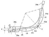
- FIG. 5 is a diagram for explaining the liquid traveling direction in the case of the cleaning nozzles 28a and 28b having the conventional arrangement shown by the two-dot chain line in FIG.
- FIG. 5 shows a state in which the peripheral side surface of the frustum-shaped side observation window 26 is developed on a plane, and the developed side observation window 26 has a fan shape.
- the cleaning nozzle 28a is arranged on the side surface 21a1 so that the liquid LQ ejection direction FD is parallel to the upper side portion UL and the lower side portion LL, as shown by a two-dot chain line in FIG.
- the cleaning nozzle 28b is disposed on the side surface 21a2 so that the liquid LQ ejection direction FD is parallel to the upper side portion UL and the lower side portion LL.
- the liquid ejected from the cleaning nozzle 28a has a width w of the opening 33a indicated by a dotted line, proceeds along the ejection direction FD1, and ejected from the cleaning nozzle 28b. Similarly, the liquid is ejected in the ejection direction FD2 with the width w of the opening 33b indicated by the dotted line.
- the liquid LQ ejected from the respective openings 33a and 33b of the cleaning nozzles 28a and 28b travels on the side surfaces 21a1 and 21a2 with a width wider than the width w due to the contact resistance between the side surfaces 21a1 and 21a2. Due to the contact resistance with the surface of the side observation window 26, when it hits the side observation window 26, it proceeds on the surface of the side observation window 26 while further expanding.
- the liquid LQ ejected from the cleaning nozzles 28a and 28b travels straight along the ejection directions FD1 and FD2, respectively, but as shown in FIG. 5, the center C far from the lower side LL from the end of the side observation window 26. It is difficult to reach.
- the liquid LQ ejected from the openings 33 a and 33 b travels on the surfaces of the side surfaces 21 a 1 and 21 a 2 and then the surface of the frustoconical side observation window 26. It is difficult to reach the center C of the lower side LL of the side observation window 26.
- the distal end portion 7 of the insertion portion 4 assumes various postures in the body during the endoscopic examination, the distal end portion 7 faces in various directions such as an upward direction, a downward direction, or an oblique direction with respect to the horizontal direction. Used.
- the distal end portion 7 rotates around the axis of the insertion portion 4, so that the cleaning nozzles 28 a and 28 b are in a gravitational direction with respect to the side observation window 26 of the lens unit 24. It is located on the upper side, located on the lower side, or located in an oblique direction.
- the liquid LQ may spread over the entire surface of the side observation window 26 when cleaning the side observation window 26, but as shown in FIG. Since the ejection directions FD1 and FD2 are difficult to reach the center C of the lower side LL of the arc-shaped side observation window 26, the cleaning property of the side observation window 26 is not high.
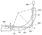
- FIG. 6 is a diagram for explaining the liquid ejection direction in the case of the cleaning nozzle 28a having the arrangement of the present embodiment shown by the solid line in FIG.
- FIG. 6 shows a state in which the circumferential side surface of the frustoconical side observation window 26 is developed on a plane.
- the cleaning nozzle 28a is disposed on the side surface 21a1 so that the ejection direction FD of the liquid LQ is inclined toward the upper side UL as shown by the solid line in FIG.
- the cleaning nozzle 28b is disposed on the side surface 21a2 so that the ejection direction FD of the liquid LQ is inclined toward the upper side UL.
- the liquid LQ from the cleaning nozzle 28a is ejected in the ejection direction FD1
- the liquid from the cleaning nozzle 28b is ejected in the ejection direction FD2.
- the liquid LQ ejected from the cleaning nozzles 28a and 28b advances straight along the ejection directions FD1 and FD2, respectively, but the cleaning nozzles 28a and 28b are arranged so that the ejection direction FD of the liquid LQ is inclined toward the upper side UL. Therefore, as shown in FIG. 6, the liquid LQ ejected from the openings 33a and 33b can easily reach the center C of the lower side LL. In the case of FIG. 6, the liquid LQ in the ejection directions FD1 and FD2 reaches the center C of the lower side LL of the arc-shaped side observation window 26.
- the liquid LQ ejected from the respective openings 33a and 33b of the cleaning nozzles 28a and 28b easily reaches every corner of the lower side LL of the side observation window 26.
- the liquid ejection direction FD1 The FD 2 reaches the center C of the lower side LL of the arc-shaped side observation window 26.
- FIG. 7 is a perspective view of the distal end portion 7 of the insertion portion 4 of the endoscope 1 having the cleaning nozzle of the conventional arrangement for explaining the range of the liquid ejected from the opening 33a of the cleaning nozzle 28a.
- the range where the liquid LQ ejected from the cleaning nozzle 28a reaches is indicated by hatching.
- the distal end portion 7 of the insertion portion 4 is used in various directions such as an upward direction, a downward direction, or an oblique direction with respect to the horizontal direction during the endoscopic examination, and the insertion portion 4 is used. It rotates around the axis. Therefore, in the case of the cleaning nozzle 28a having the conventional arrangement, the liquid may spread over the entire surface of the side observation window 26 during cleaning. However, as shown in FIG. 7, since the liquid ejection directions FD1 and FD2 do not reach the center C of the lower side portion LL of the arc-shaped side observation window 26, the liquid reaches the entire surface of the side observation window 26. It may be difficult to cross.
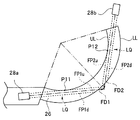
- FIG. 8 and 9 illustrate the position of the cleaning nozzle 28a provided by inclining the ejection directions FD1 and FD2 of the liquid LQ ejected from the openings 33a and 33b toward the tapered tip side of the lens unit 24.
- FIG. FIG. 8 and 9 illustrate the position of the cleaning nozzle 28a provided by inclining the ejection directions FD1 and FD2 of the liquid LQ ejected from the openings 33a and 33b toward the tapered tip side of the lens unit 24.
- the liquid LQ ejected from the openings 33a and 33b travels so as to spread on the side surfaces 21a1 and 21a2 and also spread on the surface of the side observation window 26, respectively.
- the liquid LQ is vigorous in the region defined by the extension lines FP1 and FP2 at both ends of the openings 33a and 33b along the liquid LQ ejection direction FD1 and FD2. proceed.
- the region or range defined by the extension lines FP1u and FP1d for the opening 33a and the region or range defined by the extension lines FP2u and FP2d for the opening 33b are the upper side UL and the lower side of the side observation window 26.
- the cleaning nozzle 28a is arranged so that the jet direction of the liquid LQ is inclined toward the upper side UL so as to be between LL.
- the region formed by the two imaginary lines FP2u and FP2d, which extend in parallel to the ejection direction FD2 from both ends of the width, is the upper side UL and the lower side of the sector from the other end of the sector in the cone-shaped development.
- the cleaning nozzles 28a and 28b are provided so as to be positioned between LL.
- the extension line FP1u for the cleaning nozzle 28a is a tangent to the upper side UL, and is in contact with the point P11 of the upper side UL.
- the extension line FP2u for the cleaning nozzle 28b is also a tangent to the upper side portion UL, and is in contact with the point P12 of the upper side portion UL.
- the extended line FP1d for the cleaning nozzle 28a is a tangent to the lower side LL and is in contact with the point P21 of the lower side LL.
- the extension line FP2d for the cleaning nozzle 28b is also a tangent to the lower side LL and is in contact with the point P22 of the lower side LL.
- Points P21 and P22 are end points of the lower side LL.
- the extension lines FP1u and FP1d are defined for the openings 33a and 33b of the cleaning nozzles 28a and 28b. It is preferable that the range to be set is between the upper side portion UL and the lower side portion LL of the side observation window 26.
- a part of the two ranges defined by the extended lines FP1u, FP2u and FP1d, FP2d for the openings 33a and 33b of the cleaning nozzles 28a and 28b are respectively connected to the upper side UL or the lower side LL of the side observation window 26. If exceeded, the amount of liquid flowing on the surface of the side observation window 26 is reduced.
- FIG. 10 illustrates another example of the position of the cleaning nozzle 28a provided by inclining the ejection directions FD1 and FD2 of the liquid LQ ejected from the openings 33a and 33b toward the tapered front end side of the lens unit 24.
- FIG. 10 illustrates another example of the position of the cleaning nozzle 28a provided by inclining the ejection directions FD1 and FD2 of the liquid LQ ejected from the openings 33a and 33b toward the tapered front end side of the lens unit 24.
- the extension line FP1u for the cleaning nozzle 28a is in contact with the point P11 on the upper side portion UL, and the extension line FP1d is in contact with the point P21 on the lower side portion LL.
- the extension line FP2u for the cleaning nozzle 28b is in contact with the point P12 on the upper side portion UL, and the extension line FP2d is in contact with the point P22 on the lower side portion LL.
- the ranges defined by the extension lines FP1u, FP2u and FP1d, FP2d for the openings 33a and 33b of the cleaning nozzles 28a and 28b are the upper side UL and the lower side LL of the side observation window 26, respectively.
- the cleaning nozzles 28a and 28b eject liquid LQ so that the two extension lines FP1u and FP2u are in contact with the upper side UL and the extension lines FP1d and FP2d are in contact with the end of the lower side LL. It is arranged so that the direction is inclined toward the upper side UL.
- the liquid LQ from the cleaning nozzles 28 a and 28 b can be spread over a wide range on the narrow angle side of the side observation window 26.
- FIG. 11 is a perspective view of the distal end portion 7 of the insertion portion 4 of the endoscope 1 having the cleaning nozzle of the arrangement of the present embodiment for explaining the range where the liquid ejected from the opening 33a of the cleaning nozzle 28a reaches. It is. In FIG. 11, the range in which the liquid LQ ejected from the cleaning nozzle 28a reaches is indicated by hatching.
- an endoscope having a cleaning nozzle that facilitates the transfer of cleaning liquid onto the entire peripheral surface of an observation window having a peripheral side surface formed in a cone shape. Can do.
Abstract
内視鏡1は、細長の挿入部4と、挿入部4の長手軸方向に交わる側方周囲に、テーパが設けられた錐形状に形成された周側面を有する側方観察窓26と、側方観察窓26の周側面を洗浄するための液体の噴出方向をテーパの先細りした先端側に向けて傾けて設けられた洗浄ノズル28a、28bと、を備える。
Description
本発明は、内視鏡に関し、特に、錐形状で形成された周側面を持つ観察窓を有する内視鏡に関する。
従来より、内視鏡が医療及び工業分野で広く用いられている。内視鏡は、細長の挿入部を有し、観察窓が挿入部の先端部に設けられている。観察窓を通して入射した光は、光電変換されて、被写体像である内視鏡画像が生成され、内視鏡画像は、表示装置に表示される。
また、近年は、病変部の見落とし防止等のために、広い視野で被検体を観察可能な内視鏡もある。例えば、前方視野画像と側方視野画像等の2つ以上の視野を有する広角内視鏡がある。
内視鏡は検査対象内に挿入されるため、異物が観察窓の表面に付着する場合がある。医療用内視鏡の場合、体内に残存する汚物などが観察窓に付着する。そのため、観察窓の表面に付着した異物を除去するために、観察窓の近傍に気体及び/又は液体を噴出して観察窓を洗浄する洗浄ノズルが設けられている。
例えば、特許第5583873号明細書に、挿入部の前方を観察するための前方観察窓と、側方を観察するための円錐台形レンズを有する側方観察窓を有する広角内視鏡が提案されている。その提案に係る内視鏡においても、前方観察窓と側方観察窓の各々を洗浄するための洗浄ノズルが、各観察窓の近傍に設けられている。
特に、錐形状で形成された周側面を有するレンズユニットの側方観察窓を洗浄するための2つの洗浄ノズルは、円錐台形のレンズユニットの中心軸に対して直交する方向から、円弧状の側方観察窓の周側面上に洗浄液を噴出するように、挿入部の先端部に設けられている。
しかし、円錐台形のレンズユニットの側方観察窓を洗浄するための洗浄ノズルの場合、洗浄ノズルから噴出した洗浄液は、円錐台形のレンズユニットの中心軸に対して直交する方向に噴出されるが、洗浄液が、円弧状の側方観察窓の表面の全周に渡って、伝わり難いという問題がある。
円錐台形のレンズユニットの中心軸に対して直交する方向に噴出された洗浄液は、円錐台形のレンズユニットの基端側である広角側へは流れるが、先端側である狭角側へは流れ難い傾向がある。
そこで、本発明は、錐形状で形成された周側面を持つ観察窓の全周面上に洗浄液を伝わらせ易くした洗浄ノズルを有する内視鏡を提供することを目的とする。
本発明の一態様の内視鏡は、細長の挿入部と、前記挿入部の長手軸方向に交わる側方周囲にテーパが設けられ錐形状に形成された周側面を有する第1の観察窓と、前記周側面を洗浄するための液体の噴出方向を前記テーパの先細りした先端側に向けて傾けて設けられた洗浄ノズルと、を備える。
以下、図面を参照して本発明の実施の形態を説明する。
(構成)
図1は、本発明の実施の形態に関わる、前方観察窓及び側方観察窓を挿入部の先端部に有する内視鏡と、前方観察窓と側方観察窓を洗浄する洗浄機構とを有する内視鏡装置の外観構成を示す図である。
本実施の形態の内視鏡装置は、大別して、内視鏡1と、移動可能なトロリー2に搭載された内視鏡用機器3とにより構成される。以下の説明は、軟性鏡を例として説明するが、本実施の形態は、硬性鏡においても同様に適用可能である。
(構成)
図1は、本発明の実施の形態に関わる、前方観察窓及び側方観察窓を挿入部の先端部に有する内視鏡と、前方観察窓と側方観察窓を洗浄する洗浄機構とを有する内視鏡装置の外観構成を示す図である。
本実施の形態の内視鏡装置は、大別して、内視鏡1と、移動可能なトロリー2に搭載された内視鏡用機器3とにより構成される。以下の説明は、軟性鏡を例として説明するが、本実施の形態は、硬性鏡においても同様に適用可能である。
内視鏡1は、観察対象となる体内に挿入される細長の挿入部4を有する。挿入部4は、基端側に設けられた細長の可撓管5と、可撓管5の先端側に設けられた湾曲部6と、湾曲部6の先端側に設けられた先端部7とを含む。内視鏡1は、湾曲部6を上下及び左右方向に湾曲動作させる上下及び左右のための2つの湾曲操作ノブ、レリーズボタン等の各種ボタンが設けられた操作部8と、操作部8から延出したユニバーサルケーブル9を、さらに有して構成される。
内視鏡用機器3は、観察対象部位に照射する照明光を生成する光源装置11と、撮像された映像信号に所定の画像処理を施すビデオプロセッサ12と、映像信号を観察画像として表示するモニタ13と、ユーザが各種コマンド及びデータを入力するための入力部であるキーボード14等を有している。
さらに、トロリー2の支柱には、洗浄等に用いられる液体である洗浄液、例えば水あるいは生理食塩水等を貯留するボトル15が着脱可能に取り付けられている。また、内視鏡用機器3のいずれかの装置の内部には、送気用ポンプユニット(図示せず)が配置されている。洗浄液は、送気ポンプユニットからの空気がボトル15に供給されることによって、図示しない送液チャンネルを介して各洗浄ノズルに供給される。さらに、トロリー2の棚には、体内で後述する洗浄ノズルから体内に噴出された液体や気体を吸引する吸引ユニット16が設けられている。
ユニバーサルケーブル9は、コネクタ17により光源装置11に接続されている。ユニバーサルケーブル9は、光ファイバーからなるライトガイドの他に、映像信号等を伝送する複数の信号線、チューブからなる気体及び液体の供給路(送気送液チャンネル)と排出路を含んでいる。ユニバーサルケーブル9の内視鏡用機器3側に接続するコネクタ17は、信号線とチューブとライトガイドに分岐して、それぞれの構成部位に接続している。
図2は、内視鏡1の挿入部4の先端部7の斜視図である。図3は、先端部7の左側面図である。
挿入部4の先端部7は、樹脂製の先端部本体21を有している。ゴム製のシース部材22が挿入部4を覆っている。シース部材22の先端部が、糸巻き部23により先端部本体21に対して固定されている。糸巻き部23には、接着剤が塗布されている。
先端部本体21の先端面には、挿入部4の挿入方向である先端方向に突出した直方体形状の台座部21aが形成されている。先端部本体21の先端面には、台座部21aに隣接して、レンズユニット24が突出するように設けられている。レンズユニット24は、略円柱形状を有し、前方観察窓25及び側方観察窓26を有している。すなわち、台座部21aは、挿入部4の先端部分から突出するように設けられ、レンズユニット24は、挿入部4の先端部分から突出するように台座部21aに隣接して設けられている。
前方観察窓25は、円形形状を有し、レンズユニット24の先端面に配置されている。側方観察窓26は、レンズユニット24の周側面上に、周方向に沿った円弧状に設けられ、前方観察窓25の後方側(すなわち基端側)に配置されている。レンズユニット24は、内視鏡1の撮像光学系を含み、撮像光学系は、図示しない撮像素子の前方に配置される。撮像光学系は、撮像画像を結像するために、複数のレンズ及びレンズ群を含み、各レンズは、図示しない鏡枠などにより支持されている。
図2に示すように、レンズユニット24の側方観察窓26は、円錐台形状を有する。側方観察窓26は、円錐台形状を有するため、側方観察窓26は、先細りしたテーパ部を有する。すなわち、側方観察窓26は、円錐台形のレンズの斜面部の一部であり、先細りのテーパ形状を有する。よって、側方観察窓26は、錐形状に形成された周側面を持つ円弧形状を有する。側方観察窓26の先端には、前方観察窓25が設けられている。
すなわち、側方観察窓26は、挿入部4の長手軸方向に交わる側方周囲に、基端側から先端側に向けて先細りしたテーパが設けられ錐形状に形成された周側面を有し、前方観察窓25は、側方観察窓26の円弧形状の中心に、長手軸方向に沿って光軸を有している。
よって、前方観察窓25は、挿入部4が挿入される被検体の第1の領域の第1の被検体像を取得し、側方観察窓26は、その第1の領域とは少なくとも一部が異なる被検体の第2の領域の第2の被検体像を取得する。前方観察窓25が取得する第1の被検体像は、挿入部4の長手軸方向に沿った挿入部4の前方を含む第1の領域の被検体像であり、側方観察窓26によって取得される第2の被検体像は、長手軸方向と交差する方向である挿入部4の側方を含む第2の領域の被検体像である。
台座部21aは、台座部21aの先端面が前方観察窓25と略同じ面の高さ(前方への張り出し高さ)を有する先端構造物である。前方観察窓25の表面を洗浄するための洗浄ノズル27が、台座部21aの先端面の前方観察窓25の近傍に配設されている。洗浄ノズル27は、台座部21aの先端面に平行な方向に液体を噴出する。
側方観察窓26の表面を洗浄するための2つの洗浄ノズル28aと28bは、台座部21aの、互いに反対側となる側面部に配設されている。2つの洗浄ノズル28aと28bは、円弧形状の側方観察窓26の両端の近傍に設けられている。
なお、先端部本体21には、鉗子等を挿通するための処置具挿通孔の開口部(図示せず)も設けられている。
なお、先端部本体21には、鉗子等を挿通するための処置具挿通孔の開口部(図示せず)も設けられている。
円環形状を有する照明窓29が、前方観察窓25を囲むようにレンズユニット24の先端部に設けられている。照明窓29は、先端部7の前方を照明するための照明光を照射する。さらに、円弧形状を有する照明窓30が、側方観察窓26の基端側に設けられている。照明窓30は、先端部7の主に側方、つまり先端部7の周囲の領域を照明するための照明光を照射する。
照明窓29と30の後側には、光源装置11からの照明光が出射されるライトガイド(図示せず)の先端部が配設されている。
照明窓29と側方観察窓26の間の領域の表面には、照明窓29からの照明光が側方観察窓26に入射することを防ぐ処理がなされている。側方観察窓26と照明窓30の間の領域の表面にも、照明窓30からの照明光が側方観察窓26に入射することを防ぐ処理がなされている。
照明窓29と側方観察窓26の間の領域の表面には、照明窓29からの照明光が側方観察窓26に入射することを防ぐ処理がなされている。側方観察窓26と照明窓30の間の領域の表面にも、照明窓30からの照明光が側方観察窓26に入射することを防ぐ処理がなされている。
レンズユニット24に隣接する台座部21aには、2つの洗浄ノズル28a、28bが設けられている。2つの洗浄ノズル28aと28bは、それぞれ、台座部21aの互いに平行な2つの側面21a1と21a2上に設けられている。
具体的には、洗浄ノズル28aは、側面21a1上に突出するように配設され、レンズユニット24の外周面上に配置された円弧状の側方観察窓26の一端側から、側面21a1に平行な方向に液体を噴出する。洗浄ノズル28bは、側面21a2上に突出するように配設され、レンズユニット24の外周面上に配置された円弧状の側方観察窓26の他端側から、側面21a2に平行な方向に液体を噴出する。洗浄ノズル28a、28bは、それぞれ液体を噴出する開口部33a、33bを有している。洗浄ノズル27は、液体を噴出する開口部33cを有している。
洗浄ノズル27は、開口部33cからの液体が前方観察窓25の表面に当たるように台座部21aの先端面部に設けられている。2つの洗浄ノズル28aと28bは、開口部33aと33bからの液体が側方観察窓26の表面に当たるように台座部21aの側面部に設けられている。
各開口部33a、33b、33cは、ここでは、高さhが0.5mm程度で、幅wが1mm程度の長方形を有する開口である。
図3に示すように、洗浄ノズル28aは、開口部33aからの液体LQの噴出方向FDがレンズユニット24の中心軸Oに直交する平面PLに対して所定の角度θだけ傾いた方向になるように、配設されている。洗浄ノズル28bも同様に配設されている。すなわち、洗浄ノズル28aと28bは、側方観察窓26の周側面を洗浄するために、液体LQの噴出方向FDが、周側面のテーパの先細りした先端側に向けて傾けて設けられている。
次に、洗浄ノズル28a、28bの配置についてより詳細に説明する。
図4は、側方観察窓26に対する洗浄ノズル28aの位置と傾きを説明するための先端部7の模式的左側面図である。
図4は、側方観察窓26に対する洗浄ノズル28aの位置と傾きを説明するための先端部7の模式的左側面図である。
円錐台形状の側方観察窓26の上辺部ULの直径DUは、例えば3~5mmであり、下辺部LLの直径DLは、例えば6~8mmである。上辺部ULと下辺部LLの間の距離L、すなわちレンズユニット24の軸方向における側方観察窓26の周側面部の高さは、ここでは約2mmである。
上辺部ULは、側方観察窓26の狭角側であり、下辺部LLは、側方観察窓26の広角側である。よって、洗浄ノズル28a、28bは、液体LQの噴出方向FDが狭角側に傾くように配設される。
図4に示すように側面21a1の平面に対して直交する方向から先端部7を見たときにおける、洗浄ノズル28a、28bのそれぞれの中心と、円錐台の中心軸(図3及び図4ではレンズユニット24の中心軸Oに一致する)との間の距離DDは、例えば6~8mmである。
洗浄ノズル28aと28bは、上述したように、それぞれ、台座部21aの平行な2つの側面21a1と21a2上に設けられている。
図4に示すように、側面21a1の平面に対して直交する方向から先端部7を見たときに、洗浄ノズル28aと28bは、円錐台の中心軸(図3及び図4ではレンズユニット24の中心軸Oに一致する)に直交する面に平行な平面PLに対して角度θだけ傾いている。
図4に示すように、側面21a1の平面に対して直交する方向から先端部7を見たときに、洗浄ノズル28aと28bは、円錐台の中心軸(図3及び図4ではレンズユニット24の中心軸Oに一致する)に直交する面に平行な平面PLに対して角度θだけ傾いている。
さらに、側面21a1の平面に直交する方向から先端部7を見たときに、円錐台形状の側方観察窓26の上辺部ULと下辺部LLの間の中央(距離Lの中央)を通る平面PLに対して、洗浄ノズル28aと28bの開口部33aと33bの中心(ここでは開口部33a、33bの幅方向における中心)は、距離dだけ基端方向に離れた位置に配置されている。
すなわち、洗浄ノズル28aと28bのそれぞれの開口部33aと33bの中心位置は、側方観察窓26における長手軸方向の中心位置よりも基端側に設けられている。
図4において、実線が、開口部33aの中心が平面PLから距離dだけ基端方向に離れた洗浄ノズル28aの配置位置を示し、二点鎖線が、洗浄ノズル28aの従来の配置位置を示している。
(作用)
次に、上述した洗浄ノズル28a及び28bによる、内視鏡1の側方観察窓26の洗浄作用について説明する。
次に、上述した洗浄ノズル28a及び28bによる、内視鏡1の側方観察窓26の洗浄作用について説明する。
始めに、従来の配置の洗浄ノズルから噴出した液体の経路を説明する。
図5は、図4において二点鎖線で示した従来の配置の洗浄ノズル28aと28bの場合における液体の進行方向を説明するための図である。図5は、円錐台形状の側方観察窓26の周側面を平面上に展開した状態を示し、展開された側方観察窓26は、扇形を有する。
図5は、図4において二点鎖線で示した従来の配置の洗浄ノズル28aと28bの場合における液体の進行方向を説明するための図である。図5は、円錐台形状の側方観察窓26の周側面を平面上に展開した状態を示し、展開された側方観察窓26は、扇形を有する。
洗浄ノズル28aは、図4の二点鎖線で示すように、液体LQの噴出方向FDが上辺部ULと下辺部LLに平行な方向となるように側面21a1に配設されている。洗浄ノズル28bも、同様に液体LQの噴出方向FDが上辺部ULと下辺部LLに平行な方向となるように、側面21a2に配設されている。
従来の配置の場合、図5に示すように、洗浄ノズル28aから噴出した液体は、点線で示す開口部33aの幅wを持って、噴出方向FD1に沿って進行し、洗浄ノズル28bから噴出した液体も、同様に、点線で示す開口部33bの幅wを持って、噴出方向FD2に噴出する。
実際には、洗浄ノズル28aと28bのそれぞれの開口部33aと33bから噴出した液体LQは、側面21a1と21a2との接触抵抗により、幅wよりも広い幅で側面21a1と21a2上を進行し、側方観察窓26の表面との接触抵抗により、側方観察窓26に当たるとさらに広がりながら側方観察窓26の表面上を進行する。
洗浄ノズル28aと28bから噴出した液体LQは、それぞれ噴出方向FD1とFD2に沿って真っ直ぐに進行するが、図5に示すように、側方観察窓26の端から下辺部LLの遠くの中央Cまで届き難い。図5の場合、開口部33aと33bから噴出した液体LQは、それぞれ側面21a1と21a2の表面上を進んだ後、円錐台形状の側方観察窓26の表面を進むが、液体LQは、側方観察窓26の下辺部LLの中央Cまでは届き難い。
挿入部4の先端部7は、内視鏡検査中、体内において種々の姿勢になるため、先端部7は、水平方向に対して、上方向、下方向あるいは斜め方向等、種々の方向に向いて使用される。加えて、内視鏡検査中、先端部7は、挿入部4の軸回りに回動するため、洗浄ノズル28a及び28bは、重力方向において、レンズユニット24の側方観察窓26に対して、上側に位置したり、下側側に位置したり、斜め方向に位置したりする。
よって、従来の配置の洗浄ノズル28aの場合、側方観察窓26の洗浄時、液体LQは、側方観察窓26の表面全体に渡る場合もあるが、図5に示すように、液体LQの噴出方向FD1,FD2は円弧状の側方観察窓26の下辺部LLの中央Cまで届き難いため、側方観察窓26の洗浄性は高くない。
次に、本実施の形態の配置の洗浄ノズルによる液体の噴出を説明する。
図6は、図4において実線で示した本実施の形態の配置の洗浄ノズル28aの場合における液体の噴出方向を説明するための図である。図6は、円錐台形状の側方観察窓26の展開図周側面を平面上に展開した状態を示している。
図6は、図4において実線で示した本実施の形態の配置の洗浄ノズル28aの場合における液体の噴出方向を説明するための図である。図6は、円錐台形状の側方観察窓26の展開図周側面を平面上に展開した状態を示している。
洗浄ノズル28aは、図4の実線で示したように、液体LQの噴出方向FDが上辺部UL側に傾くように側面21a1に配設されている。洗浄ノズル28bも、同様に液体LQの噴出方向FDが上辺部UL側に傾くように側面21a2に配設されている。図6においては、洗浄ノズル28aからの液体LQは噴出方向FD1に噴出し、洗浄ノズル28bからの液体は噴出方向FD2に噴出する。
洗浄ノズル28aと28bから噴出した液体LQは、それぞれ噴出方向FD1とFD2に沿って真っ直ぐに進行するが、洗浄ノズル28aと28bは液体LQの噴出方向FDが上辺部UL側に傾くように配設されているため、図6に示すように開口部33aと33bから噴出した液体LQは、下辺部LLの中央Cまで届き易くなる。図6の場合、噴出方向FD1,FD2の液体LQは、円弧状の側方観察窓26の下辺部LLの中央Cまで届いている。
すなわち、洗浄ノズル28aと28bのそれぞれの開口部33aと33bから噴出した液体LQは、側方観察窓26の下辺部LLの隅々までは届き易く、図6の場合、液体の噴出方向FD1,FD2は、円弧状の側方観察窓26の下辺部LLの中央Cまで届いている。
図7は、洗浄ノズル28aの開口部33aから噴出した液体の届く範囲を説明するための、従来の配置の洗浄ノズルを有する内視鏡1の挿入部4の先端部7の斜視図である。図7において、洗浄ノズル28aから噴出した液体LQが到達する範囲は、斜線で示されている。
上述したように、挿入部4の先端部7は、内視鏡検査中、水平方向に対して、上方向、下方向あるいは斜め方向等、種々の方向に向いて使用され、かつ、挿入部4の軸回りに回動する。よって、従来の配置の洗浄ノズル28aの場合、洗浄時、液体が側方観察窓26の表面全体に渡る場合もある。しかし、図7に示すように、液体の噴出方向FD1,FD2は円弧状の側方観察窓26の下辺部LLの中央Cまで届いていないため、液体は、側方観察窓26の表面全体に渡り難い場合もある。
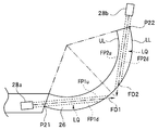
図8及び図9は、開口部33aと33bから噴出される液体LQの噴出方向FD1,FD2をレンズユニット24における先細りした先端側に向けて傾けて設けた洗浄ノズル28aの位置を説明するための図である。
開口部33aと33bから噴出する液体LQは、それぞれ側面21a1と21a2上で広がり、かつ側方観察窓26の表面上でも広がるようにして進行する。しかし、図8及び図9で示すように、液体LQの噴出方向FD1,FD2に沿った開口部33aと33bの両端部の延長線FP1,FP2により規定される領域内では、液体LQは勢いよく進行する。
開口部33aについての延長線FP1uとFP1dにより規定される領域すなわち範囲、及び開口部33bについての延長線FP2uとFP2dにより規定される領域すなわち範囲が、側方観察窓26の上辺部ULと下辺部LLの間になるように、洗浄ノズル28aは、液体LQの噴出方向が上辺部UL側に傾くように配設される。
すなわち、開口部33aの幅wとその幅の両端から噴出方向FD1に平行に延びる2本の仮想線である延長線FP1u,FP1dとにより形成される領域、及び、開口部33bの幅wとその幅の両端から噴出方向FD2に平行に延びる2本の仮想線である延長線FP2u, FP2dとにより形成される領域が、錐形状の展開図における扇形の他端から扇形の上辺部ULと下辺部LLの間に位置するように、各洗浄ノズル28aと28bは設けられている。
図8では、洗浄ノズル28aについての延長線FP1uは、上辺部ULとの接線であり、上辺部ULの点P11で接している。図8では、洗浄ノズル28bについての延長線FP2uも、上辺部ULとの接線であり、上辺部ULの点P12で接している。
図9では、洗浄ノズル28aについての延長線FP1dは、下辺部LLとの接線であり、下辺部LLの点P21で接している。図9では、洗浄ノズル28bについての延長線FP2dも、下辺部LLとの接線であり、下辺部LLの点P22で接している。点P21とP22は、下辺部LLの端点である。
従って、液体LQの噴出方向が上辺部UL側に傾くように洗浄ノズル28aと28bを配設したときに、洗浄ノズル28aと28bの各々の開口部33aと33bについての延長線FP1uとFP1dにより規定される範囲が、側方観察窓26の上辺部ULと下辺部LLの間になることが好ましい。
洗浄ノズル28aと28bの各々の開口部33aと33bについての延長線FP1u,FP2uとFP1d,FP2dにより規定される2つの範囲の一部が、側方観察窓26の上辺部UL又は下辺部LLを越えると、側方観察窓26の表面に流れる液体の量が減る。
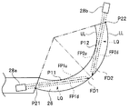
図10は、開口部33aと33bから噴出される液体LQの噴出方向FD1,FD2をレンズユニット24における先細りした先端側に向けて傾けて設けた洗浄ノズル28aの位置の他の例を説明するための図である。
図10では、洗浄ノズル28aについての延長線FP1uは、上辺部UL上の点P11で接していると共に、延長線FP1dは、下辺部LL上の点P21で接している。洗浄ノズル28bについての延長線FP2uも、同様に、上辺部UL上の点P12で接していると共に、延長線FP2dは、下辺部LL上の点P22で接している。
すなわち、図10では、洗浄ノズル28aと28bのそれぞれの開口部33aと33bについての延長線FP1u,FP2uとFP1d,FP2dにより規定される範囲が、側方観察窓26の上辺部ULと下辺部LLの間になり、かつ2本の延長線FP1u,FP2uが上辺部ULに接し、かつ延長線FP1d,FP2dが下辺部LLの端部に接するように、洗浄ノズル28aと28bが、液体LQの噴出方向が上辺部UL側に傾くように配設されている。
図10に示す配置のとき、洗浄ノズル28aと28bからの液体LQを、側方観察窓26の狭角側の広い範囲に渡って行き渡らせることができる。
図10に示す配置のとき、洗浄ノズル28aと28bからの液体LQを、側方観察窓26の狭角側の広い範囲に渡って行き渡らせることができる。
図11は、洗浄ノズル28aの開口部33aから噴出した液体の届く範囲を説明するための、本実施の形態の配置の洗浄ノズルを有する内視鏡1の挿入部4の先端部7の斜視図である。図11において、洗浄ノズル28aから噴出した液体LQが到達する範囲は、斜線で示されている。
レンズユニット24の中心軸Oに対する、側方観察窓26の周側面の傾斜角度α(例えば25度)のとき(図4参照)、図8から図10に説明した範囲で洗浄ノズルの開口部の中心を平面PLから距離dだけ基端方向に離し、洗浄ノズル28a、28bからの液体LQの噴出方向を上辺部UL側に所定の角度θだけ傾くように配設すれば、図11に示すように液体LQは、側方観察窓26の広角側の中央Cまで届き易くなる。
以上説明したように、上述した実施の形態によれば、錐形状で形成された周側面を持つ観察窓の全周面上に洗浄液を伝わらせ易くした洗浄ノズルを有する内視鏡を提供することができる。
本発明は、上述した実施の形態に限定されるものではなく、本発明の要旨を変えない範囲において、種々の変更、改変等が可能である。
本出願は、2016年1月18日に日本国に出願された特願2016-6995号を優先権主張の基礎として出願するものであり、上記の開示内容は、本願明細書、請求の範囲に引用されるものとする。
Claims (12)
- 細長の挿入部と、
前記挿入部の長手軸方向に交わる側方周囲にテーパが設けられ、錐形状に形成された周側面を有する第1の観察窓と、
前記周側面を洗浄するための液体の噴出方向を前記テーパの先細りした先端側に向けて傾けて設けられた洗浄ノズルと、
を備えることを特徴とする内視鏡。 - 前記洗浄ノズルの開口部の中心位置は、前記第1の観察窓における前記長手軸方向の中
心位置よりも基端側に設けられていることを特徴とする請求項1に記載の内視鏡。 - 前記開口部の幅と前記幅の両端から前記噴出方向に平行に延びる2本の仮想線とにより形成される領域が、前記錐形状の展開図における扇形の一端から前記扇形の上辺部と下辺部の間に位置するように、前記洗浄ノズルは設けられることを特徴とする請求項2に記載の内視鏡。
- 前記2本の仮想線のうちの一方が前記扇形の前記上辺部に接すると共に、前記2本の仮想線のうちの他方が前記下辺部の端部に接するように、前記洗浄ノズルは設けられていることを特徴とする請求項3に記載の内視鏡。
- 前記第1の観察窓は、前記錐形状に形成された周側面を持つ円弧形状を有することを特徴とする請求項1に記載の内視鏡。
- 前記第1の観察窓の円弧形状の中心に、前記長手軸方向に沿って光軸を有する第2の観察窓を有することを特徴とする請求項2に記載の内視鏡。
- 前記第2の観察窓は、前記挿入部が挿入される被検体の第1の領域の第1の被検体像を取得し、
前記第1の観察窓は、前記第1の領域とは少なくとも一部が異なる前記被検体の第2の領域の第2の被検体像を取得することを特徴とする請求項6に記載の内視鏡。 - 前記第1の被検体像は、前記長手軸方向に沿った前記挿入部の前方を含む前記第1の領域の被検体像であり、
前記第2の被検体像は、前記長手軸方向と交差する方向である前記挿入部の側方を含む前記第2の領域の被検体像であることを特徴とする請求項7に記載の内視鏡。 - 前記挿入部の先端部分から突出するように設けられた台座部を有し、
前記洗浄ノズルは、前記台座部に設けられていることを特徴とする請求項1に記載の内視鏡。 - 前記挿入部の先端部分から突出するように前記台座部に隣接して設けられたレンズユニットを有し、
前記第1の観察窓は、前記レンズユニットに設けられていることを特徴とする請求項9に記載の内視鏡。 - 前記第1の観察窓は、前記周側面に円弧形状に設けられ、
前記洗浄ノズルは、前記円弧形状の前記第1の観察窓の両端の近傍に2つ設けられていることを特徴とする請求項1に記載の内視鏡。 - 前記洗浄ノズルは、前記テーパの先細りした先端側に向けて略4度傾けて設けられていることを特徴とする請求項1に記載の内視鏡。
Priority Applications (3)
| Application Number | Priority Date | Filing Date | Title |
|---|---|---|---|
| CN201680021412.0A CN107529946A (zh) | 2016-01-18 | 2016-11-08 | 内窥镜 |
| JP2017521013A JP6165396B1 (ja) | 2016-01-18 | 2016-11-08 | 内視鏡 |
| US16/035,916 US11042020B2 (en) | 2016-01-18 | 2018-07-16 | Endoscope having observation window with circumferential side surface and cleaning nozzles directed to circumferential side surface |
Applications Claiming Priority (2)
| Application Number | Priority Date | Filing Date | Title |
|---|---|---|---|
| JP2016006995 | 2016-01-18 | ||
| JP2016-006995 | 2016-01-18 |
Related Child Applications (1)
| Application Number | Title | Priority Date | Filing Date |
|---|---|---|---|
| US16/035,916 Continuation US11042020B2 (en) | 2016-01-18 | 2018-07-16 | Endoscope having observation window with circumferential side surface and cleaning nozzles directed to circumferential side surface |
Publications (1)
| Publication Number | Publication Date |
|---|---|
| WO2017126196A1 true WO2017126196A1 (ja) | 2017-07-27 |
Family
ID=59362059
Family Applications (1)
| Application Number | Title | Priority Date | Filing Date |
|---|---|---|---|
| PCT/JP2016/083058 WO2017126196A1 (ja) | 2016-01-18 | 2016-11-08 | 内視鏡 |
Country Status (3)
| Country | Link |
|---|---|
| US (1) | US11042020B2 (ja) |
| CN (1) | CN107529946A (ja) |
| WO (1) | WO2017126196A1 (ja) |
Families Citing this family (2)
| Publication number | Priority date | Publication date | Assignee | Title |
|---|---|---|---|---|
| CA3053536C (en) * | 2017-02-15 | 2021-12-14 | Kourosh E. Zanganeh | High temperature camera probe |
| JP6916236B2 (ja) * | 2019-03-27 | 2021-08-11 | Hoya株式会社 | 内視鏡 |
Citations (3)
| Publication number | Priority date | Publication date | Assignee | Title |
|---|---|---|---|---|
| JP2002238906A (ja) * | 2001-02-21 | 2002-08-27 | Fuji Photo Optical Co Ltd | 超音波内視鏡 |
| JP2011120863A (ja) * | 2009-11-11 | 2011-06-23 | Fujifilm Corp | 内視鏡 |
| JP2014132964A (ja) * | 2013-01-09 | 2014-07-24 | Olympus Medical Systems Corp | 内視鏡装置 |
Family Cites Families (16)
| Publication number | Priority date | Publication date | Assignee | Title |
|---|---|---|---|---|
| CN102341028B (zh) * | 2009-11-06 | 2014-08-13 | 奥林巴斯医疗株式会社 | 内窥镜 |
| EP2425760B1 (en) * | 2009-11-06 | 2013-01-16 | Olympus Medical Systems Corp. | Endoscope system |
| CN102469924B (zh) * | 2009-11-06 | 2016-02-10 | 奥林巴斯株式会社 | 内窥镜装置以及内窥镜 |
| CN102665529B (zh) * | 2010-07-08 | 2015-04-15 | 奥林巴斯医疗株式会社 | 内窥镜 |
| JP5261518B2 (ja) * | 2011-03-01 | 2013-08-14 | 富士フイルム株式会社 | 内視鏡 |
| WO2012132598A1 (ja) * | 2011-03-31 | 2012-10-04 | オリンパスメディカルシステムズ株式会社 | 内視鏡撮像ユニットの組立方法及び内視鏡 |
| JP5815967B2 (ja) * | 2011-03-31 | 2015-11-17 | 東京エレクトロン株式会社 | 基板洗浄装置及び真空処理システム |
| JP5274719B2 (ja) * | 2011-04-07 | 2013-08-28 | オリンパスメディカルシステムズ株式会社 | 内視鏡及び内視鏡用照明装置 |
| WO2014050236A1 (ja) | 2012-09-28 | 2014-04-03 | オリンパスメディカルシステムズ株式会社 | 洗浄機構を有する内視鏡装置 |
| CN104507376B (zh) * | 2012-11-05 | 2016-08-24 | 奥林巴斯株式会社 | 内窥镜 |
| CN105939650B (zh) * | 2014-02-14 | 2018-01-30 | 奥林巴斯株式会社 | 内窥镜系统 |
| JP5942047B2 (ja) * | 2014-03-17 | 2016-06-29 | オリンパス株式会社 | 内視鏡システム |
| EP3111824A4 (en) * | 2014-03-31 | 2017-10-11 | Olympus Corporation | Endoscope system |
| JP5953443B2 (ja) * | 2014-04-08 | 2016-07-20 | オリンパス株式会社 | 内視鏡システム |
| CN106102550B (zh) * | 2014-05-16 | 2018-04-03 | 奥林巴斯株式会社 | 内窥镜系统 |
| WO2015198981A1 (ja) * | 2014-06-27 | 2015-12-30 | オリンパス株式会社 | 内視鏡システム |
-
2016
- 2016-11-08 CN CN201680021412.0A patent/CN107529946A/zh active Pending
- 2016-11-08 WO PCT/JP2016/083058 patent/WO2017126196A1/ja active Application Filing
-
2018
- 2018-07-16 US US16/035,916 patent/US11042020B2/en active Active
Patent Citations (3)
| Publication number | Priority date | Publication date | Assignee | Title |
|---|---|---|---|---|
| JP2002238906A (ja) * | 2001-02-21 | 2002-08-27 | Fuji Photo Optical Co Ltd | 超音波内視鏡 |
| JP2011120863A (ja) * | 2009-11-11 | 2011-06-23 | Fujifilm Corp | 内視鏡 |
| JP2014132964A (ja) * | 2013-01-09 | 2014-07-24 | Olympus Medical Systems Corp | 内視鏡装置 |
Also Published As
| Publication number | Publication date |
|---|---|
| US20180325359A1 (en) | 2018-11-15 |
| US11042020B2 (en) | 2021-06-22 |
| CN107529946A (zh) | 2018-01-02 |
Similar Documents
| Publication | Publication Date | Title |
|---|---|---|
| JP5583873B1 (ja) | 洗浄機構を有する内視鏡装置 | |
| US10441151B2 (en) | Endoscope | |
| JP6050211B2 (ja) | 内視鏡 | |
| JP2015533300A (ja) | マルチカメラ内視鏡 | |
| JP2014524819A (ja) | マルチカメラ内視鏡 | |
| JP2014524303A (ja) | 多重観察要素内視鏡 | |
| JP2005168770A (ja) | 内視鏡 | |
| JP6050221B2 (ja) | 内視鏡 | |
| WO2017183366A1 (ja) | 器具挿入補助具 | |
| JP5608580B2 (ja) | 内視鏡 | |
| WO2017126196A1 (ja) | 内視鏡 | |
| JP6130993B2 (ja) | 大腸用内視鏡、及び、大腸用内視鏡システム | |
| JP6165396B1 (ja) | 内視鏡 | |
| JP2019505327A (ja) | 音波視覚化能力を備えたシステム | |
| JP6430739B2 (ja) | 内視鏡 | |
| US10799103B2 (en) | Endoscope having image acquisition windows and corresponding cleaning nozzles on front and circumferential surfaces | |
| JP6151196B2 (ja) | 内視鏡 | |
| JP6280823B2 (ja) | 内視鏡 | |
| CN111031891B (zh) | 内窥镜 | |
| WO2016185830A1 (ja) | 内視鏡及び内視鏡システム | |
| JP6172743B2 (ja) | 内視鏡 | |
| JP2005168606A (ja) | 内視鏡 | |
| JP5400719B2 (ja) | 送気送液装置 |
Legal Events
| Date | Code | Title | Description |
|---|---|---|---|
| ENP | Entry into the national phase |
Ref document number: 2017521013 Country of ref document: JP Kind code of ref document: A |
|
| 121 | Ep: the epo has been informed by wipo that ep was designated in this application |
Ref document number: 16886435 Country of ref document: EP Kind code of ref document: A1 |
|
| NENP | Non-entry into the national phase |
Ref country code: DE |
|
| 122 | Ep: pct application non-entry in european phase |
Ref document number: 16886435 Country of ref document: EP Kind code of ref document: A1 |