WO2017126186A1 - コネクタ着脱装置及びコネクタ着脱方法 - Google Patents
コネクタ着脱装置及びコネクタ着脱方法 Download PDFInfo
- Publication number
- WO2017126186A1 WO2017126186A1 PCT/JP2016/082562 JP2016082562W WO2017126186A1 WO 2017126186 A1 WO2017126186 A1 WO 2017126186A1 JP 2016082562 W JP2016082562 W JP 2016082562W WO 2017126186 A1 WO2017126186 A1 WO 2017126186A1
- Authority
- WO
- WIPO (PCT)
- Prior art keywords
- connector
- holder
- attaching
- clamps
- pair
- Prior art date
- Legal status (The legal status is an assumption and is not a legal conclusion. Google has not performed a legal analysis and makes no representation as to the accuracy of the status listed.)
- Ceased
Links
Images





Classifications
-
- H—ELECTRICITY
- H01—ELECTRIC ELEMENTS
- H01R—ELECTRICALLY-CONDUCTIVE CONNECTIONS; STRUCTURAL ASSOCIATIONS OF A PLURALITY OF MUTUALLY-INSULATED ELECTRICAL CONNECTING ELEMENTS; COUPLING DEVICES; CURRENT COLLECTORS
- H01R43/00—Apparatus or processes specially adapted for manufacturing, assembling, maintaining, or repairing of line connectors or current collectors or for joining electric conductors
- H01R43/26—Apparatus or processes specially adapted for manufacturing, assembling, maintaining, or repairing of line connectors or current collectors or for joining electric conductors for engaging or disengaging the two parts of a coupling device
Definitions
- the present invention relates to a connector attaching / detaching apparatus and a connector attaching / detaching method, and more particularly, to an apparatus and method for attaching / detaching two connectors that can be fitted and connected.
- Cables and connectors that are used in special environments, for example, in radiation environments such as nuclear facilities, are subject to deterioration because their insulation materials deteriorate when exposed to radiation. It is desirable to perform such replacement work under a radiation environment by remote control using a robot such as a manipulator in order to avoid radiation exposure of workers.
- Japanese Patent Application Laid-Open No. 60-146481 discloses an apparatus that enables a cable to be attached and detached by remote control.
- the apparatus body plate (1) installed horizontally.
- the power supply side insertion guide (2) is fixed to the first end side.
- the power supply side insertion guide (2) has recesses (3, 4).
- the power supply side connectors (7, 8) attached to the detachable plates (5, 6) are attached to the recesses (3, 4) from above.
- a handle (9, 10) is attached to the upper end portion of the detachable plate (5 and 6), and the detachable plate (5 and 6) is moved up and down through the handle (9, 10) to thereby move the connector. (7, 8) can be attached to and detached from the recess (3, 4).
- An electric motor side insertion guide (11) is installed to be detachable from the power supply insertion guide (2).
- recesses (17, 18) are formed at positions corresponding to the recesses (3, 4) of the power supply side insertion guide (2).
- the motor side connectors (21, 22) attached to the detachable plates (19, 20) are mounted on the recesses (17, 18) from above.
- the handles (23, 24) are attached to the upper ends of the detachable plates (19, 20), and the detachable plates ( 19, 20) can be attached to and detached from the recesses (17, 18) of the electric power connector (21, 22) by moving up and down.
- the detachable operation lever (14) is rotated in the first direction, and the motor is driven.
- the side insertion guide (11) is moved along the guide rod (15) in a direction away from the power supply side insertion guide (2).
- the detachable plates (19, 20) are lifted through the handles (23, 24), and the motor side connectors (21, 22) are lifted from the motor side insertion guide (11). Let go.
- the respective connectors are inserted into the power source side insertion guide (2) and the motor side insertion guide (11), and in this state, the detachment operation is performed.
- the lever (14) is rotated in a second direction opposite to the first direction, and the motor side insertion guide (11) is moved along the guide rod (15) toward the power source side insertion guide (2).
- the apparatus described in the above document has a structure in which the detachable plate (5, 6, 19, 20) is mounted by loosely fitting into the recess (3, 4, 17, 18) of the insertion guide (2, 11). For this reason, the detachable plates (5, 6, 19, 20) may be rattled in the insertion guides (2, 11), and the connectors may not be connected with high accuracy.
- the present invention eliminates the above-mentioned conventional problems, can easily attach and detach the connector to and from the device, and can hold the connectors without rattling and connect the connectors with high accuracy. It is an object of the present invention to provide a connector attaching / detaching device and attaching / detaching method.
- a connector attaching / detaching device is a connector attaching / detaching device that connects and disconnects a first connector and a second connector that can be attached to and detached from each other.
- the first connector In the opened state, the first connector can be introduced from the side facing the second holder, and in the closed state, the first connector is engaged with at least the side surface.
- One pair And it has a clamp.
- the first holder supports the pair of clamps so that the pair of clamps can pivot about the distal end side of the pair of clamps with respect to the second holder. And a protrusion that contacts the first connector when the first connector is introduced and rotates the clamp in the closing direction is formed at the distal end of each clamp. Is preferred.
- the back plate has a guide portion for guiding the introduction of the first connector.
- the first holder is disposed on the back side of the back plate and extends in a linear direction extending in the relative movement direction of the first holder and the second holder. It is preferable to have a slide plate that is slidably supported along the back plate.
- the slide plate when the slide plate is slid in the separating direction with respect to the second holder, the slide plate abuts against the side surfaces of the pair of clamps in the closed state to lock the closed state. It is preferable to have a pair of lock portions.
- the pair of clamp protrusions are pressed toward the second holder to release the clamp. It is preferable to have a pair of pressing parts that rotate in the direction.
- the pair of clamps have a front wall that engages with the front portion of the first connector.
- a connector attaching / detaching method of the present invention for solving the above-mentioned problems is a connector attaching / detaching method for connecting and removing the first and second connectors using the connector attaching / detaching device.
- the step of attaching the first connector to the first holder by engaging, the moving means to be operated, and the relative position of the first holder and the second holder are changed in the proximity direction, whereby the first And connecting the connector and the second connector for connection.
- the moving means is operated to change the relative positions of the first holder and the second holder in the separating direction, whereby the first connector and the second connector It is preferable to perform the removal by releasing the fitting.
- the first connector can be easily attached to and detached from the first holder.
- the first connector can be held without rattling to engage with the side surface of the first connector when the clamp is closed, the first connector and the second connector Can be connected with high accuracy.
- FIG. 1 is a front view of a connector attaching / detaching device according to a first embodiment of the present invention.
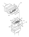
- FIG. 2 is a view showing the fitting structure of both connectors in a separated state in which the fitting connection is released with respect to the fixed side connector and the moving side connector which are attached and detached using the connector attaching / detaching apparatus of FIG.
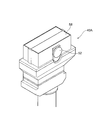
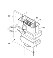
- FIG. 3 is a perspective view showing a modification of the moving-side connector of FIG. 2 having a shutter at the fitting port.
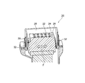
- 4 is a cross-sectional view of the fixed connector for explaining the positional relationship between the first holding member and the first case member of the fixed connector shown in FIG. 2 and the floating structure of the first holding member.
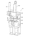
- FIG. 5 is a perspective view of the connector attaching / detaching device of FIG. 1.
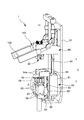
- FIG. 6 is an enlarged view of a portion A in FIG.
- FIG. 7 is a diagram for explaining a state from when the locking portion of the moving side connector slides in the guide groove of the back plate in an engaged state until the moving side connector is attached to the back plate.
- FIG. 8 is a conceptual diagram for explaining an operation procedure until the movable connector is mounted on the movable holder.
- FIG. 9 is a conceptual diagram for explaining an operation procedure until the attached movable connector is removed from the movable holder.
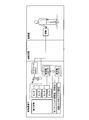
- FIG. 10 is a schematic view showing an example of a layout in which the connector attaching / detaching device is operated by remote operation using a manipulator in a special environment, and the moving connector is attached to and detached from the fixed connector.
- FIG. 10 is a schematic view showing an example of a layout in which the connector attaching / detaching device is operated by remote operation using a manipulator in a special environment, and the moving connector is attached to and detached from the fixed connector.
- FIG. 11 is a perspective view of the connector attaching / detaching device according to the second embodiment of the present invention, and shows the movable side connector and the fixed side connector in a fitted connection state.
- FIG. 12 is a perspective view of the connector attaching / detaching apparatus shown in FIG.
- a connector attaching / detaching apparatus 1 shown in FIG. 1 is a connector attaching / detaching apparatus for connecting and disconnecting two detachable connectors 20 and 40, and a nuclear reactor is arranged in a special environment, for example, a nuclear power plant. Under the radiation environment, it is preferable that the connectors 20 and 40 can be attached and detached even by remote operation using a manipulator (robot) or the like.
- a manipulator robot
- one of the two connectors 20, 40 is a fixed connector 20 that is fixedly fixed in the connector attaching / detaching device 1, and the other connector 40 is a fixed connector in the connector attaching / detaching device 1.
- 20 is a moving-side connector 40 attached so as to be able to move toward and away from 20.
- the movable connector 40 corresponds to the “first connector” in the present invention
- the fixed connector 20 corresponds to the “second connector” in the present invention.
- the fixed connector 20 as the second connector mainly includes a plurality of first signal transmission members 22, a first holding member 24, a first case member 26, and a first positioning means 28, and
- the moving-side connector 40 mainly includes a plurality of second signal transmission members 42, a second holding member 44, a second case member 46, and second positioning means 48. Further, the fixed-side connector 20 is located in a position where the insulation coating of the cable to which the fixed-side connector 20 is connected is unlikely to deteriorate under a special environment (radiation environment), for example, in a building where the nuclear reactor is installed and from the nuclear reactor.
- the cable that is fixed to a position such as a remote wall, ceiling, or floor and to which the fixed connector 40 is connected is connected to the wiring located outside the room, or is covered with a shielding plate such as lead inside the room. It is connected to the wiring located in the enclosed place (space).
- the moving-side connector 40 as the first connector is a connector connected to one end of a cable connected to a plurality of sensors or the like that perform various measurements in relation to a nuclear reactor or the like, and includes the sensor, the cable, and the moving-side connector. 40 includes a sensor unit (see FIG. 10). Since the moving side connector 40 is used at a position relatively close to a nuclear reactor or the like having a high radiation dose, the cable to which the moving side connector 40 is connected is easily deteriorated. The entire sensor unit including the sensor unit needs to be replaced relatively early in consideration of cable deterioration. As a method for exchanging the entire sensor unit, for example, as shown in FIG.
- the manipulator grips the moving connector 40, While dragging the entire sensor unit, the manipulator is transported to a shielded space (Box) prepared in the reactor building in advance or to a sensor unit replacement place provided at a location away from the reactor, and then the grip of the manipulator is released.
- the used sensor unit is placed in a shielded space or a sensor unit replacement place, and then the manipulator grips the protruding grip portion 54 of the moving connector 40 constituting the new sensor unit, and lifts the moving connector 40.
- the connector attaching / detaching device 1 while dragging in the state Thereby transported to the position of the moving holder 80, it is desirable to replace the entire sensor unit in a way by mounting the moving-side connector 40 to the movable holder 80.
- the fixed-side connector 20 is configured as a plug optical connector in which a plurality of first signal transmission members 22 having a total of 20 cores in 4 stages ⁇ 5 rows are exposed.
- the movable connector 40 has a plurality of second signal transmission members 42 arranged at positions corresponding to the first signal transmission members 22 of the fixed connector 20, and each second signal transmission member 42 is a cylindrical member. The case where it is configured as a receptacle optical connector existing in a covered state is shown.
- the fixed connector 20 can be configured as a receptacle optical connector
- the moving connector 40 can be configured as a plug optical connector.
- the first signal transmission member 22 of the fixed-side connector 20 is mainly composed of an optical fiber (not shown) and a ceramic ferrule in which this optical fiber is inserted and fixed.
- the first contact portion 22a that comes into contact with the second signal transmission member 42 is provided.
- the first holding member 24 is provided to hold the plurality of first signal transmission members 22 in a predetermined arrangement state, and can be configured as a metal block, for example.
- the first case member 26 surrounds at least the first holding member 24 and is a metal shell that is fitted and connected to the second case member 46 of the movable connector 40 when the connectors 20 and 40 are fitted and connected.
- the first holding member 24 is elastically connected to the first holding member 24 via a first elastic member 32 such as a spring member, and is held by the first signal transmission member 22.
- a so-called floating structure in which the first holding member 24 is swung in the inner space of the first case member 26 in, for example, a double arrow direction F can be employed.
- the first contact portion 22a of the first signal transmission member 22 can be accurately positioned and contacted with the second signal transmission member 42 of the movable connector 40 without being damaged. .
- the floating structure of the first holding member 24 is close to both side walls of the first case member 26 by arranging a pair of spring members 32 only on the narrow surfaces on both sides of the first holding member 24. Although it is configured to swing only in the separating direction (double arrow direction F), a pair of other spring materials are arranged on the wide surfaces on both sides of the first holding member 24.
- the first case member 26 can be configured to swing not only in the double arrow direction F but also in a direction orthogonal to the double arrow direction.
- the first positioning means 28 is formed integrally with either the first holding member 24 or the first case member 26, and is formed as a positioning hole in the first holding member 24 in FIG.
- the moving-side connector 40 includes a second signal transmission member 42 including an optical fiber (not shown) and a ceramic ferrule in which the optical fiber is inserted and fixed.
- the first signal transmission member 22 includes a second contact portion 42 a that contacts the first contact portion 22 a.
- FIG. 2 shows a case where a stainless steel cylindrical member 50 covering the periphery of the second signal transmission member 42 is further formed. With this configuration, when the connectors 20 and 40 are connected to each other, the fixed side is shown.
- the first signal transmission member 22 of the connector 20 is fitted into a cylindrical member 50 made of a metal such as stainless steel, brass, aluminum, zinc, etc., up to a position where it contacts the second contact portion 42a of the second signal transmission member 42. It is comprised so that.
- the second holding member 44 is provided to hold the plurality of second signal transmission members 42 in a predetermined arrangement state, and can be configured as a metal block.
- the second case member 46 surrounds at least the second holding member 44 and is a metal shell that is fitted and connected to the first case member 26 of the fixed connector 20 when the connectors 20 and 40 are fitted and connected.
- the second holding member 44 is elastically connected to the second holding member 44 via a second elastic material (not shown) such as a spring material, and holds the second signal transmission member 42.
- a structure in which the second holding member 44 can swing in the internal space of the second case member 46, a so-called floating structure, can be employed, whereby the second signal transmission can be performed when the connectors 20 and 40 are fitted and connected.
- the second contact portion 42a of the member 42 can be accurately positioned and contacted with the first contact portion 22a of the fixed connector 20 without being damaged.
- the outer surface of the second case member 46 is locked to a locked portion 82 of a movable holder 80, which will be described later, constituting the connector attaching / detaching device 1, and the locked portion 82 can be slid in the locked state. It has the outer surface which formed the latching
- the second positioning means 48 has a shape that engages with the first positioning means 28, and is formed integrally with any part of the second holding member 44 and the second case member 46 corresponding to the first positioning means 28.
- the first positioning means 28 is formed as a positioning hole in the first holding member 24 of the stationary connector 20
- the second positioning means 48 is made of metal in the second holding member 44 of the moving connector 40. The structure in the case of being integrally formed as a positioning pin is shown.
- the first and second contact portions 22a and 42a are damaged. More accurate positioning contact can be achieved without this.
- At least one of the moving-side connector 40 and the fixed-side connector 20 may have a pair of shutters 58 that are releasably closed on the respective fitting port sides as in the modification shown in FIG.
- the moving connector 40 and the fixed connector 20 are optical connectors, for example, if foreign matter such as dust adheres to the surfaces of the contact portions 22a and 42a of the signal transmission members 22 and 42, the one optical fiber to the other optical fiber. Problems such as inferior light transmission efficiency are likely to occur. However, it is difficult to remove dust adhering to the contact portions 22a and 42a, particularly by remote operation using a manipulator. However, by providing the pair of shutters 58, foreign matter such as dust is as much as possible on the contact portions 22a and 42a. Adhesion can be prevented.
- the pair of shutters 58 is closed until at least the connectors 20 and 40 enter the mating and connecting operation, and are opened immediately before the mating and connecting operation to open the fitting port.
- the shutter 58 moves in a direction to close the fitting opening immediately after the two connectors are separated. It is preferable.
- the opening direction of the shutter 58 is preferably an outward opening direction in order to prevent foreign matter such as dust from entering the case members 26 and 46 where the contact portions 22a and 42a are located. .
- the connector attaching / detaching apparatus 1 having the above-described structure and suitable for fitting and connecting the fixed connector 20 and the moving connector 40 is a second holder in the present invention as shown in FIGS. It mainly includes a fixed holder 60, a movable holder 80 as a first holder in the present invention, and a moving mechanism 100 as a moving means.
- the fixed holder 60 is a member for mounting and holding the fixed connector 20, and is fixed to the base plate 61 of the connector attaching / detaching device 1 by screws, welding, or the like.
- the base plate 61 can be fixed to, for example, a wall, floor, ceiling, etc. with bolts or welding.
- the fixed holder 60 has a concave portion 62 having a shape corresponding to the outer shape of the fixed-side connector 20 and a cover 63 that covers the opening side of the concave portion 62, and the fixed-side connector 20 is disposed in the concave portion 62. When the cover 63 is attached, the fixed connector 20 is held in the fixed holder 60 without rattling.
- the specific configuration of the fixed holder 60 is not particularly limited as long as the fixed side connector 20 can be mounted and held at a predetermined position and orientation in the connector attaching / detaching device 1.
- the movable holder 80 is disposed to face the fixed holder 60.
- the movable holder 80 has a movable block 81 that is guided by two linear shafts 64 arranged in parallel with the base plate 61 and can move in the uniaxial direction X to approach and separate from the fixed holder 60.
- the movable holder 80 is arranged so as to be openable and closable on the side of the movable connector 40. When the movable holder 80 is opened, the movable connector 40 can be introduced from the side facing the fixed holder 60, and in the closed state, the movable connector 80 is movable.
- a pair of clamps 86 for engaging and positioning the holding connector 40 in the horizontal direction W and the vertical direction (uniaxial direction X) are provided. Each clamp 86 is provided with a front wall 86 a that engages with the front portion of the moving connector 40.
- each clamp 86 with respect to the fixed holder 60 is provided with a projecting piece 86b that abuts against the connector 40 when the movable connector 40 is introduced and rotates the clamp 86 in the closing direction.
- the movable holder 80 has a back plate 84 disposed on the back side of the pair of clamps 86 and on the front side of the movable block 81.
- a shaft portion 87 is formed on the front side of the back plate 84 so as to correspond to the distal end portion of the clamp 86 with respect to the fixed holder 60 and rotatably support the clamp 86.
- the back plate 84 is fixed to the movable block 81 with screws or the like, and can move in the uniaxial direction X together with the movable block 81.
- the back plate 84 also has a function as a connector mounting member. That is, as shown in FIG. 7, the back plate 84 has a shape corresponding to the locking portion 52 provided on the outer surface of the second case member 46 of the moving connector 40, and the locking portion 52 is slidably slidable.
- a guide groove 82 is formed as a guide portion that is moved and engaged.
- the guide groove 82 is formed as a notch extending from the proximal end portion of the back plate 84 to the distal end portion side with respect to the fixed holder 60, and the groove width of the guide groove 82 is determined by the proximal end portion. It is formed slightly wider on the side. As a result, the locking portion 52 of the moving connector 40 can be smoothly inserted into the guide groove 82.
- the locking portion 52 of the movable connector 40 is formed so as to protrude from the outer surface of the second case member 46, and a plate-like portion 52a and a circular engagement portion 52b formed on the plate-like portion 52a. Therefore, the guide groove 82 has a stepped portion that protrudes inward and engages between the plate-like portion 52a and the circular engaging portion 52b.
- the movable connector 40 can be attached to the back plate 84.
- the back plate 84 projects to the front side on the mounting direction L side (distal end side with respect to the fixed holder) of the moving connector 40, and moves to the moving connector 40.
- the distal end face of the clamps 86, 86 with respect to the fixed holder (the outer surface of the protruding piece 86b) is in contact with the clamp 86, and the fitting pressing force from the moving connector 40 is applied when the two connectors 20, 40 are fitted together.
- a contact block 88 is formed to be received via the clamps 86 and 86.
- a pin-shaped opening stopper 92 that restricts the opening (rotation) of the clamp 85 is provided on the side of the clamp 86 of the back plate 84.
- the movable holder is disposed on the back side of the back plate 84 and on the front side of the movable block 81 and is slidably supported by the back plate 84.
- two rails 93 are laid along the uniaxial direction X on the back surface of the back plate 84, and sliders 94 that run on the rails 93 are provided on the front surface of the slider plate 94.
- the slide plate 94 is slidable along the rail 93 with respect to the movable block 81 and the back plate 84 independently of the movement of the movable block 81 along the linear shaft 64.
- the movement of the slide plate 94 can be performed manually or indirectly or remotely via a robot such as a manipulator, or can be performed using an actuator (not shown).
- each protruding pin 90 is slidably disposed in an opening formed in the contact block 88, and is configured to protrude and retract from the opening in conjunction with movement along the uniaxial direction X of the slide plate 94. Yes.
- the slide plate 94 has a pair of lock portions 94a and 94a that protrude forward and abut against the side surface of the clamp 86 that is in a closed state when the slide plate 94 slides away from the fixed holder 60 to lock the closed state. Is provided.
- the slide plate 94 is formed with a knob 96 as an operation unit operated by a worker or a robot such as a manipulator.
- the shape of the knob 96 can be the same as that of the protruding grip portion 54 of the moving connector 40. Therefore, after the attachment of the movable connector 40 to the back plate 84 is completed, a robot such as an operator or a manipulator grips the knob 96 so that the slide plate 94 moves away from the fixed holder 60 with respect to the back plate 84.
- the pair of lock portions 94a and 94a of the slide plate 94 can hold the pair of clamps 86 and 86 so as not to open from both sides.
- the knob 96 is gripped and the slide plate 94 is slid in the opposite direction with respect to the back plate 84, the locks of the clamps 86 and 86 by the lock portions 94a and 94a are released.
- the moving-side connector 40 can be attached to the movable holder 80 by remote control.
- This remote operation can be performed using, for example, a robot such as a manipulator.
- the remote operation is performed by a small camera attached to a manipulator (robot), for example, an operator (human) in a control room at a distance of several tens of meters or more from the reactor building. It is possible to control the operation of the manipulator while viewing the monitor image displayed.
- the protruding gripping portion 54 gripped by a manipulator or the like on the surface of the connector 40 opposite to the side on which the locking portion 52 is provided. Is preferably provided.
- the moving mechanism 100 causes the movable holder 80 to move in the uniaxial direction X with respect to the fixed holder 60, and holds the fitting connection state of the movable connector 40 with respect to the fixed connector 20, and the fixed connector 20. It is provided in order to generate both of the separating forces required when separating the moving connector 40 from the connector.
- the connectors 20 and 40 have a configuration in which the case members 26 and 46 and the holding members 24 and 44 are elastically connected to each other via an elastic material.
- the contact pressure between the pair of signal transmission members 22 and 42 requires an elastic force (eg, spring force) of about 1 kg.
- spring force e.g, spring force
- a self-propelled manipulator (robot) with a joint that is used for remote operation cannot withstand a reaction force of 100 kg, and complicated operations including rotating operations become difficult.
- the moving mechanism 100 it is more preferable to employ a toggle mechanism that is a boost mechanism as the moving mechanism 100.
- a toggle mechanism that is a boost mechanism
- the shape of the operation lever 102 is not particularly limited. As an example, in FIG. 1, the operation lever 102 is configured by a round bar, but may be configured by a plate-shaped piece.
- the operation lever 102 By configuring the operation lever 102 with a round bar, for example, even when the operation lever 102 is operated by a manipulator, the operation when the operation lever 102 is pushed up and down by the manipulator is only an operation on one axis. This is because the moving mechanism 100 can be operated with a simple structure.
- a shock absorber (not shown) such as an air damper filled with air is further provided in order to reduce the reaction force. Also good.
- the connector attaching / detaching apparatus 1A includes, as a moving means, an air cylinder 100A that moves in a uniaxial direction along, for example, a rail. It is to be prepared.
- this connector attaching / detaching apparatus 1A for example, when a manipulator pushes an operation switch (not shown), an air cylinder 100A as a moving means connected to an electric system is operated, and a movable holder 80A equipped with a moving connector 40A is mounted.
- the buckle 30 pivotally supported on the fixed connector 20A is operated by another air cylinder 104.
- the tip hook of the buckle 30 that has been pushed up and displaced downward with the engaged pin 56 protruding from the moving connector 40, the fitting connection state of both the connectors 20 and 40 is maintained. It is a configuration.
- the connector attaching / detaching method is a method of connecting and removing both connectors 20, 40 or 20 ⁇ / b> A, 40 ⁇ / b> A that can be fitted and connected using the connector attaching / detaching device 1 or 1 ⁇ / b> A. Considering the above, a case where the operation is performed by remotely operating a robot such as a manipulator will be described.
- the manipulator that is remotely operated is used to grip the protruding grip portion 54 of the moving connector 40, and the gripping moving connector 40 is moved to the position of the movable holder 80 of the connector attaching / detaching device 1.
- Transport. The movable holder 80 before the mounting of the moving connector 40 is maintained in a state in which the pair of guide members 86, 86 are opened by the push-up action of the protruding pin 90, so that the moving connector 40 can be easily inserted and mounted. (FIG. 8A).
- the moving-side connector 40 gripped by the manipulator is moved so that the protruding locking portion 52 of the moving-side connector 40 engages with the guide groove 82 formed in the back plate 84 of the movable holder 80.
- 40 is abutted against the front surface of the back plate 84 (FIG. 8B), and the manipulator lowers the protruding locking portion 52 of the moving-side connector 40 in the state where it is engaged with the guide groove 82 of the back plate 84. It is moved in the direction away from the fixed holder 60.
- the movable connector 40 While holding the manipulator, the movable connector 40 is moved downward until the outer surface of the protruding piece 86b of the clamp 86 hits the contact block 88 connected to the lower end of the back plate 84, and the protruding pin 90 contacts. It is lowered until it is buried in the block 88 (FIG. 8D).
- the manipulator pushes down the knob 96 of the slide plate 94 to move the slide plate 94 downward (side away from the fixed holder) relative to the back plate 84 (FIG. 8E).
- the lock portions 94a and 94a which are both arm portions of the slide plate 94, face and contact the outer surface of the side walls of the pair of clamps 86 and 86, so that the closed state of the clamps 86 and 86 is locked.
- the mounting and fixing of the movable connector 40 to the movable holder 80 is completed.
- the moving mechanism 100 is operated by pushing up the operation lever 102 of the moving mechanism 100 by the manipulator, and the movable holder 80 is moved in the uniaxial direction X toward the fixed holder 60.
- the fitting of the case member 46 to the first case member 26 is started, and then the second positioning means 48 of the movable connector 40 is started to engage the first positioning means 28 of the fixed connector 20, and further the first
- the first contact portions 22a of the plurality of first signal transmission members 22 held by the first holding member 24 elastically connected to the case member 26 are elastically connected to the corresponding second case members 46, respectively.
- the second contact portion 42a of the plurality of second signal transmission means 42 held by the second holding member 44 is contacted with the second contact portion 42a.
- the movable side connector 40 is separated from the fixed side connector 20 in the fitted connection state by moving the movable holder 80 downward by the push-down operation of the operation lever 102 of the moving mechanism 100 by the manipulator.
- the slide plate 94 is moved upward (on the fixed holder 60 side) relative to the back plate 84, and the pair of clamps 86, 86 are opened.
- the lock by the lock portions 94a and 94a of the slide plate 94 that has prevented the above is released.
- the protrusion pin 90 pushes up the protrusion 86a of the clamp 86 in conjunction with the upward movement of the slide plate 94, so that the pair of clamps 86, 86 are rotated around the shaft portion 87 and opened (FIG. 9 ( a)).
- the movable connector 40 can be removed from the movable holder 80 by grasping the protruding gripping portion 54 of the movable connector 40 with the manipulator and lifting it upward (FIG. 9B).
- the side connector 40 can be transported to a predetermined position by a manipulator.
- the above description is merely an example of the embodiment of the present invention, and various modifications can be made within the scope of the claims.
- the two connectors 20 and 40 are configured as optical connectors.
- only optical connectors are used.
- the connector is not limited to this, and may be a connector having another configuration such as an electrical connector.
- the connectors can be easily attached and detached by remote operation using a manipulator or the like. It has become possible to provide a connector attaching / detaching apparatus and attaching / detaching method capable of accurately contacting and connecting signal transmitting members positioned and opposed to each other without being damaged.
Landscapes
- Engineering & Computer Science (AREA)
- Manufacturing & Machinery (AREA)
- Manufacturing Of Electrical Connectors (AREA)
Abstract
本発明は、コネクタの装置への取り付け及び装置からの取り外しを容易に行うことができ、しかもコネクタをがたつきなく保持してコネクタ同士を精度よく連結することができるコネクタの着脱装置等を提供する。 コネクタの着脱装置(1)は、第1のコネクタ(40)を保持する第1のホルダ(80)と、第1のホルダ(80)に対向して配置されるとともに、第2のコネクタ(20)を保持する第2のホルダ(60)と、第1のコネクタ(40)と第2のコネクタ(20)との相対位置を変化させて接続及び抜去を行うように、第1のホルダ(80)及び第2のホルダ(60)の少なくとも一方を移動させる移動手段(100)と、を備える。少なくとも第1のホルダ(80)は、第1のコネクタ(40)の側方に開閉自在に配置され、開放された状態では、第2のホルダ(60)に対向する側からの第1のコネクタ(40)の導入を可能とし、閉鎖された状態では第1のコネクタ(40)の少なくとも側面に係合する1対のクランプ(86)を有する。
Description
本発明は、コネクタ着脱装置及びコネクタ着脱方法に関し、特に、嵌合接続可能な2つのコネクタを着脱する装置及び方法に関する。
特殊環境下、例えば原子力施設等の放射線環境下で使用されるケーブルやコネクタは、放射線照射を受けてその絶縁材料が劣化するため、定期的に交換する必要がある。このような放射線環境下での交換作業は、作業員の放射線被爆を回避するためマニピュレータ等のロボットを用いた遠隔操作によって行うことが望ましい。
特開昭60-146481号公報には、遠隔操作によりケーブルの着脱を可能とする装置が開示されている。この装置は、該公報第1、第2図に開示されるように(括弧内の符号は当該公報の実施形態における参照符号を指すものである。)、水平に設置された本体プレート(1)の第1端側に電源側挿入ガイド(2)が固定されている。電源側挿入ガイド(2)には凹部(3,4)が形成されている。凹部(3,4)には着脱プレート(5及び6)に取り付けられた電源側コネクタ(7,8)が、上方から装着されている。すなわち、着脱プレート(5及び6)の上端部には取手(9,10)が取り付けられており、この取手(9,10)を介して着脱プレート(5及び6)を上下動させることによりコネクタ(7,8)の凹部(3,4)に対する着脱を行うことができる。電源挿入ガイド(2)に対して離接可能に電動機側挿入ガイド(11)が設置されている。電動機側挿入ガイド(11)には電源側挿入ガイド(2)の凹部(3,4)に対応する位置に凹部(17,18)が形成されている。凹部(17,18)には着脱プレート(19,20)に取り付けられた電動機側コネクタ(21,22)が上方から装着されている。すなわち電源側コネクタ(7,8)の場合同様、着脱プレート(19,20)の上端部には取手(23,24)が取り付けられており、この取手(23,24)を介して着脱プレート(19,20)を上下動させることにより電動儀側コネクタ(21,22)の凹部(17,18)に対する着脱を行うことができる。
このように構成された装置を用いて電源側コネクタ(7,8)と電動機側コネクタ(21,22)とを抜去するには着脱操作レバー(14)を第1の方向に回動させ、電動機側挿入ガイド(11)をガイド棒(15)に沿って電源側挿入ガイド(2)から離れる方向に移動させる。そして、電動機が故障して取替えが必要な場合には取手(23,24)を介して着脱プレート(19,20)を持ち上げて電動機側コネクタ(21,22)を電動機側挿入ガイド(11)から離脱させる。電源側コネクタ(7,8)と電動機側コネクタ(21,22)とを連結するには各コネクタを電源側挿入ガイド(2)及び電動機側挿入ガイド(11)に挿入し、この状態で着脱操作レバー(14)を上記第1の方向とは逆の第2の方向に回動させ、電動機側挿入ガイド(11)をガイド棒(15)に沿って電源側挿入ガイド(2)の方向へ移動させる。
しかしながら、上記文献記載の装置は、着脱プレート(5,6,19,20)を挿入ガイド(2,11)の凹部(3,4,17,18)に遊嵌させることにより装着する構造であるため、着脱プレート(5,6,19,20)は挿入ガイド(2,11)内でがたつく虞があり、コネクタ同士を精度高く連結することができない場合がある。
本発明は、上記従来の問題を解消し、コネクタの装置への取り付け及び装置からの取り外しを容易に行うことができ、しかもコネクタをがたつきなく保持してコネクタ同士を精度よく連結することができるコネクタの着脱装置及び着脱方法を提供することを目的とする。
本発明は上記課題を解決するためになされたものであり、本発明のコネクタ着脱装置は、互いに着脱可能な第1のコネクタ及び第2のコネクタの接続と抜去とを行うコネクタ着脱装置であって、第1のコネクタを保持する第1のホルダと、第1のホルダに対向して配置されるとともに、第2のコネクタを保持する第2のホルダと、第1のコネクタと第2のコネクタとの相対位置を変化させて接続及び抜去を行うように、第1のホルダ及び第2のホルダの少なくとも一方を移動させる移動手段と、を備え、少なくとも第1のホルダは、第1のコネクタの側方に開閉自在に配置され、開放された状態では、第2のホルダに対向する側からの第1のコネクタの導入を可能とし、閉鎖された状態では第1のコネクタの少なくとも側面に係合する1対のクランプを有するものである。
なお、本発明のコネクタ着脱装置にあっては、第1のホルダは、1対のクランプの、第2のホルダに対する遠位端部側を回動中心として1対のクランプを回動可能に支持するバックプレートを有し、各クランプの遠位端部には、第1のコネクタの導入時に該第1のコネクタに当接して該クランプを閉鎖方向に回動させる突片が形成されていることが好ましい。
また、本発明のコネクタ着脱装置にあっては、バックプレートは、第1のコネクタの導入を案内するガイド部を有することが好ましい。
さらに、本発明のコネクタ着脱装置にあっては、第1のホルダは、バックプレートの背面側に配置されるとともに、第1のホルダ及び第2のホルダの相対移動方向に延在する直線方向に沿ってバックプレートにスライド可能に支持されたスライドプレートを有することが好ましい。
さらに、本発明のコネクタ着脱装置にあっては、スライドプレートは、第2のホルダに対する離間方向にスライドされた際に閉鎖状態にある1対のクランプの側面に当接して該閉鎖状態をロックする1対のロック部を有することが好ましい。
さらに、本発明のコネクタ着脱装置にあっては、スライドプレートは、第2のホルダに対する近接方向にスライドされた際に1対のクランプの突片を第2のホルダ側に押圧してクランプを開放方向へ回動させる1対の押圧部を有することが好ましい。
加えて、本発明のコネクタ着脱装置にあっては、1対のクランプは第1のコネクタの正面部に係合する前壁を有することが好ましい。
また、上記課題を解決するための本発明のコネクタ着脱方法は、上記コネクタ着脱装置を用いて第1及び第2のコネクタの接続と抜去とを行うコネクタ着脱方法であって、第1のホルダの開放状態にある1対のクランプの間に、第2のホルダに対向する側から第1のコネクタを導入する工程と、1対のクランプを閉鎖し、該クランプを第1のコネクタの少なくとも側面に係合させることにより第1のホルダへ第1のコネクタを装着する工程と、移動手段を作動させ、第1のホルダと第2のホルダの相対位置を近接方向へ変化させることにより、第1のコネクタと第2のコネクタとを嵌合させ接続を行う工程と、を含むものである。
なお、本発明のコネクタ着脱方法にあっては、移動手段を作動させ、第1のホルダと第2のホルダの相対位置を離間方向へ変化させることにより、第1のコネクタと第2のコネクタとの嵌合を解除し抜去を行うことが好ましい。
本発明によれば、第1のコネクタの側面に係合するクランプを設けるとともに該クランプを側方に開閉自在に構成したことから、第1のホルダへの第1のコネクタの取り付け及び取り外しを容易に行うことができ、しかもクランプが閉鎖した状態では第1のコネクタの側面に係合するためがたつきなく第1のコネクタを保持することができるため、第1のコネクタと第2のコネクタとを精度よく連結することができる。
次に、本発明の実施形態について図面を参照しながら以下で説明する。
図1に示すコネクタ着脱装置1は、着脱可能な2つのコネクタ20、40同士の接続と抜去とを行なうコネクタ着脱装置であって、特に特殊環境下、例えば原子力発電所のように原子炉が配置された放射線環境下で、好適にはマニピュレータ(ロボット)などを用いた遠隔操作であっても両コネクタ20、40同士の着脱動作を行なうことができる構成を有している。
<コネクタ>
図示例では、2つのコネクタ20、40のうち一方のコネクタ20は、コネクタ着脱装置1内に不動に固定される固定側コネクタ20であり、他方のコネクタ40はコネクタ着脱装置1内に固定側コネクタ20に対し接近および離隔移動することができるように取り付けられた移動側コネクタ40である。また、この実施形態においては、移動側コネクタ40が本発明における「第1のコネクタ」に対応し、固定側コネクタ20が本発明における「第2のコネクタ」に対応する構成とし、第1のコネクタとしての移動側コネクタ40をマニピュレータ等のロボットを用いてコネクタ着脱装置1に取り付け又は取り外す例について説明するが、これとは逆の構成としてもよい。
図示例では、2つのコネクタ20、40のうち一方のコネクタ20は、コネクタ着脱装置1内に不動に固定される固定側コネクタ20であり、他方のコネクタ40はコネクタ着脱装置1内に固定側コネクタ20に対し接近および離隔移動することができるように取り付けられた移動側コネクタ40である。また、この実施形態においては、移動側コネクタ40が本発明における「第1のコネクタ」に対応し、固定側コネクタ20が本発明における「第2のコネクタ」に対応する構成とし、第1のコネクタとしての移動側コネクタ40をマニピュレータ等のロボットを用いてコネクタ着脱装置1に取り付け又は取り外す例について説明するが、これとは逆の構成としてもよい。
第2のコネクタとしての固定側コネクタ20は、複数の第1信号伝達部材22と、第1保持部材24と、第1ケース部材26と、第1位置決め手段28とで主に構成され、また、移動側コネクタ40は、複数の第2信号伝達部材42と、第2保持部材44と、第2ケース部材46と、第2位置決め手段48とで主に構成されている。また、固定側コネクタ20は、特殊環境(放射線環境)下で、固定側コネクタ20が接続されたケーブルの絶縁被覆等が劣化しにくい位置、例えば原子炉が設置された建屋内でかつ原子炉から離れた壁、天井、床などの位置に固定され、固定側コネクタ40が連結されたケーブルは、部屋の外側に位置する配線に接続されているか、あるいは、部屋の内側で鉛等の遮蔽板によって囲われている場所(空間)に位置する配線に接続されている。
第1のコネクタとしての移動側コネクタ40は、原子炉等に関連して各種測定を行う複数のセンサ等に接続されたケーブルの一端に接続されるコネクタであって、センサ、ケーブルおよび移動側コネクタ40を含むセンサユニットを構成している(図10参照)。そして、移動側コネクタ40は、放射線量が高い原子炉等から比較的近い位置で使用されるため、移動側コネクタ40が接続されているケーブルが劣化しやすい環境下にあり、移動側コネクタ40を含めたセンサユニット全体としてケーブル劣化を考慮した比較的早期の交換が必要になる。センサユニット全体を交換する方法としては、例えば図10に示すように、マニピュレータを用いた遠隔操作によって、移動側コネクタ40を固定側コネクタ20から分離した後に、マニピュレータに移動側コネクタ40を把持させ、そのままセンサユニット全体を引きずりながら、原子炉建屋内に予め用意した遮蔽空間(Box)、あるいは原子炉から離れた場所に設けたセンサユニット交換場所までマニピュレータに搬送させてから、マニピュレータの把持を開放して使用済みのセンサユニットを遮蔽空間またはセンサユニット交換場所に置き、次いで、マニピュレータに、新品のセンサユニットを構成する移動側コネクタ40の突状把持部54を把持させ、移動側コネクタ40を持ち上げた状態で引きずりながらコネクタ着脱装置1の可動ホルダ80の位置まで搬送させて、可動ホルダ80に移動側コネクタ40を取り付けることによる方法でセンサユニット全体を交換することが望ましい。
この実施形態では、図2に示すように、固定側コネクタ20が、4段×5列の合計20芯からなる複数の第1信号伝達部材22を露出した状態で配列したプラグ光コネクタとして構成し、移動側コネクタ40が、固定側コネクタ20の第1信号伝達部材22に対応する位置に配列された複数の第2信号伝達部材42を有し、各第2信号伝達部材42が筒状部材で覆われた状態で存在するレセプタクル光コネクタとして構成した場合を示す。なお、本発明では、固定側コネクタ20をレセプタクル光コネクタとして構成し、移動側コネクタ40をプラグ光コネクタとして構成することも可能である。
固定側コネクタ20の第1信号伝達部材22は、光ファイバ(図示せず)と、この光ファイバを内挿固定したセラミックス製のフェルールとで主に構成され、フェルールの先端に、移動側コネクタ40の第2信号伝達部材42と接触する第1接触部22aを有する。
第1保持部材24は、複数の第1信号伝達部材22を所定の配列状態を保持するために設けられ、例えば金属製のブロックとして構成することができる。
第1ケース部材26は、第1保持部材24の周りを少なくとも包囲し、両コネクタ20、40の嵌合接続時に、移動側コネクタ40の第2ケース部材46と嵌合連結される金属製のシェル部分であって、第1保持部材24とは、図4に示すように、例えばバネ材のような第1弾性材32を介して弾性的に連結されていて、第1信号伝達部材22が保持されている第1保持部材24が、第1ケース部材26の内部空間において、例えば両矢印方向Fに揺動する、いわゆるフローティング構造を採用することができ、これによって、両コネクタ20、40の嵌合接続時に、第1信号伝達部材22の第1接触部22aが、破損することなく移動側コネクタ40の第2信号伝達部材42との正確な位置決め接触をすることが可能になる構成としている。なお、第1保持部材24のフローティング構造は、図4では、第1保持部材24の両側狭幅面のみに1対のバネ材32を配置して、第1ケース部材26の両側壁に対して接近・離隔する方向(両矢印方向F)にだけ揺動するように構成しているが、さらに、バネ材32を第1保持部材24の両側広幅面にも1対の他のバネ材を配置して、第1ケース部材26の両矢印方向Fだけではなく、この両矢印方向に直交する方向にも揺動するように構成することもできる。
第1位置決め手段28は、第1保持部材24および第1ケース部材26のいずれかに一体的に形成され、図2では第1保持部材24に位置決め穴として形成され、両コネクタ20、40の嵌合接続時に、移動側コネクタ40の第2位置決め手段48に嵌合することによって、固定側コネクタ20の第1信号伝達部材22と、移動側コネクタ40の第2信号伝達部材42との正確な位置決め接触を可能にするために設けられている。
移動側コネクタ40は、第2信号伝達部材42が、光ファイバ(図示せず)と、この光ファイバを内挿固定したセラミックス製のフェルールとで構成され、フェルールの先端に、固定側コネクタ20の第1信号伝達部材22の第1接触部22aと接触する第2接触部42aを有する。なお、図2では、第2信号伝達部材42の周りを覆うステンレス製の筒状部材50をさらに形成した場合を示しており、この構成によって、両コネクタ20、40の嵌合接続時に、固定側コネクタ20の第1信号伝達部材22は、第2信号伝達部材42の第2接触部42aに接触する位置まで、ステンレス鋼、真鍮、アルミニウム、亜鉛などの金属製の筒状部材50内に嵌入されるように構成されている。
第2保持部材44は、複数の第2信号伝達部材42を所定の配列状態を保持するために設けられ、金属製のブロックとして構成することができる。
第2ケース部材46は、第2保持部材44の周りを少なくとも包囲し、両コネクタ20、40の嵌合接続時に、固定側コネクタ20の第1ケース部材26と嵌合連結される金属製のシェル部分であって、第2保持部材44とは、例えばばね材のような第2弾性材(図示せず)を介して弾性的に連結されていて、第2信号伝達部材42が保持されている第2保持部材44が、第2ケース部材46の内部空間において揺動可能な構造、いわゆるフローティング構造を採用することができ、これによって、両コネクタ20、40の嵌合接続時に、第2信号伝達部材42の第2接触部42aが、破損することなく固定側コネクタ20の第1接触部22aとの正確な位置決め接触をすることが可能になる構成としている。また、第2ケース部材46の外面には、コネクタ着脱装置1を構成する、後述する可動ホルダ80の被係止部82に係止され、係止状態のまま被係止部82をスライド移動可能な係止部52を形成した外面を有する。
第2位置決め手段48は、第1位置決め手段28と係合する形状をもち、第1位置決め手段28に対応する、第2保持部材44および第2ケース部材46のいずれかの部分に一体的に形成され、両コネクタ20、40の嵌合接続時に、固定側コネクタ20の第1位置決め手段28に嵌合することによって、固定側コネクタ20の第1信号伝達部材22と、移動側コネクタ40の第2信号伝達部材42との正確な位置決め接触を可能にするために設けられている。なお、図2では、第1位置決め手段28を、固定側コネクタ20の第1保持部材24に位置決め穴として形成され、第2位置決め手段48を、移動側コネクタ40の第2保持部材44に金属製の位置決めピンとして一体的に形成された場合の構成を示している。この構成によって、特に多芯(例えば各20本以上)の第1および第2信号伝達部材22、42を配列した光コネクタの場合には、第1および第2接触部22a、42aが、破損することなくより正確な位置決め接触させることができる。
また、移動側コネクタ40および固定側コネクタ20の少なくとも一方は、図3に示す変形例のように、それぞれの嵌合口側に、開放可能に閉鎖される1対のシャッタ58を有するものでもよい。移動側コネクタ40および固定側コネクタ20が例えば光コネクタの場合、それぞれの信号伝達部材22、42の接触部22a、42aの表面にゴミ等の異物が付着すると、一方の光ファイバから他方の光ファイバへの光の伝送効率が劣るなどの不具合が生じやすい。しかしながら、特にマニピュレータを用いた遠隔操作では、接触部22a、42aに付着したゴミを取り除くことは難しいが、上記1対のシャッタ58を設けることによって、接触部22a、42aに極力ゴミ等の異物が付着するのを防止することができる。
加えて、1対のシャッタ58は、コネクタ20、40同士が少なくとも嵌合接続動作に入るまでは閉鎖した状態とし、嵌合接続動作直前に開いて嵌合口を開放した後に、両コネクタ20、40が嵌合接続されるとともに、両コネクタ20、40の嵌合接続を解除する場合には、両コネクタの分離を行った直後に、前記シャッタ58が嵌合口を閉鎖する方向に移動する構造を有することが好ましい。なお、シャッタ58の開放方向は、接触部22a、42aが位置する両ケース部材26、46の内部にゴミ等の異物が侵入するのを極力防止するため、外向きの開放方向であることが好ましい。
<コネクタ着脱装置>
上述した構造を有する、固定側コネクタ20と移動側コネクタ40とを嵌合接続するのに適したコネクタ着脱装置1は、図1及び図5に示すように、本発明における第2のホルダとしての固定ホルダ60と、本発明における第1のホルダとしての可動ホルダ80と、移動手段としての移動機構100と、を主に備えている。
上述した構造を有する、固定側コネクタ20と移動側コネクタ40とを嵌合接続するのに適したコネクタ着脱装置1は、図1及び図5に示すように、本発明における第2のホルダとしての固定ホルダ60と、本発明における第1のホルダとしての可動ホルダ80と、移動手段としての移動機構100と、を主に備えている。
(固定ホルダ)
固定ホルダ60は、図1及び図5に示すように、固定側コネクタ20を装着して保持するための部材であって、コネクタ着脱装置1のベースプレート61にねじや溶接等で固定されている。ベースプレート61は、例えば壁、床、天井等にボルトや溶接等で固定することができる。固定ホルダ60は固定側コネクタ20の外形に対応した形状の凹部62が形成されるとともに該凹部62の開口側を覆うカバー63を有しており、該凹部62内に固定側コネクタ20が配置され、カバー63が取り付けられた状態では固定側コネクタ20はがたつきなく固定ホルダ60内に保持される。なお、固定ホルダ60の具体的な構成としては、コネクタ着脱装置1内の所定の位置および向きに、固定側コネクタ20を装着できかつ保持できる構成であればよく、特に限定はしない。
固定ホルダ60は、図1及び図5に示すように、固定側コネクタ20を装着して保持するための部材であって、コネクタ着脱装置1のベースプレート61にねじや溶接等で固定されている。ベースプレート61は、例えば壁、床、天井等にボルトや溶接等で固定することができる。固定ホルダ60は固定側コネクタ20の外形に対応した形状の凹部62が形成されるとともに該凹部62の開口側を覆うカバー63を有しており、該凹部62内に固定側コネクタ20が配置され、カバー63が取り付けられた状態では固定側コネクタ20はがたつきなく固定ホルダ60内に保持される。なお、固定ホルダ60の具体的な構成としては、コネクタ着脱装置1内の所定の位置および向きに、固定側コネクタ20を装着できかつ保持できる構成であればよく、特に限定はしない。
(可動ホルダ)
可動ホルダ80は、図1及び図5に示すように、固定ホルダ60に対向して配置されている。可動ホルダ80は、ベースプレート61と平行に配置された2本のリニアシャフト64に案内されて固定ホルダ60に対する接近および離隔する一軸方向Xへの移動が可能な可動ブロック81を有する。
可動ホルダ80は、図1及び図5に示すように、固定ホルダ60に対向して配置されている。可動ホルダ80は、ベースプレート61と平行に配置された2本のリニアシャフト64に案内されて固定ホルダ60に対する接近および離隔する一軸方向Xへの移動が可能な可動ブロック81を有する。
可動ホルダ80は、移動側コネクタ40の側方に開閉自在に配置され開放された状態では固定ホルダ60に対向する側からの移動側コネクタ40の導入を可能とし、閉鎖された状態では移動側コネクタ40の少なくとも側面に係合して移動側コネクタ40の横方向W及縦方向(一軸方向X)の位置決めおよび保持を行なう1対のクランプ86を有している。また、各クランプ86には、移動側コネクタ40の正面部に係合する前壁86aが設けられている。さらに、各クランプ86の、固定ホルダ60に対する遠位端部には、移動側コネクタ40の導入時に該コネクタ40に当接して該クランプ86を閉鎖方向に回動させる突片86bが設けられている。
また、可動ホルダ80は、1対のクランプ86の背面側でかつ可動ブロック81の前面側に配置されたバックプレート84を有している。バックプレート84の前面側には、クランプ86の、固定ホルダ60に対する遠位端部に対応して配置され、該クランプ86を回動可能に支持する軸部87が形成されている。バックプレート84は、可動ブロック81にネジ等で固定され、可動ブロック81と一緒に一軸方向Xに移動可能である。
バックプレート84はコネクタ取付部材としての機能をも有している。すなわち、バックプレート84には、図7に示すように、移動側コネクタ40の第2ケース部材46の外面に設けた係止部52に対応した形状をもち、係止部52を分離可能にスライド移動させて係合連結されるガイド部としてのガイド溝82が形成されている。
このガイド溝82は、バックプレート84の、固定ホルダ60に対する近位端部から遠位端部側へ向けて延びる切欠きとして形成されており、ガイド溝82の溝幅は、該近位端部側において僅かに広く形成されている。これにより、移動側コネクタ40の係止部52をガイド溝82内にスムーズに挿入することができる。また、この実施形態では、移動側コネクタ40の係止部52が、第2ケース部材46の外面から突出して形成され、板状部52aとこの板状部52a上に形成した円形係合部52bとからなる突状係止部として構成されているため、ガイド溝82には、内側へ張り出して板状部52aと円形係合部52bとの間に係合する段部がされており、これにより移動側コネクタ40をバックプレート84に取り付けることができる。
また、図1、図5及び図6に示すように、バックプレート84には、移動側コネクタ40の装着方向L側(固定ホルダに対する遠位端部側)において正面側に突出し、移動側コネクタ40の装着時にはクランプ86、86の、固定ホルダに対する遠位側端面(突片86bの外面)が当接し、また、両コネクタ20、40の嵌合接続時には移動側コネクタ40からの嵌合押圧力をクランプ86、86を介して受け止める当接ブロック88が形成されている。
また、バックプレート84の、クランプ86の側方にはクランプ85の開度(回動)を制限するピン状の開度ストッパ92が設けられている。
可動ホルダは、図1、図5及び図6に示すように、バックプレート84の背面側でかつ可動ブロック81の前面側に配置されるとともに、バックプレート84にスライド可能に支持されたスライドプレート94を有している。図示例では、バックプレート84の背面に一軸方向Xに沿って2本のレール93が敷設され、スライダプレート94の前面には各レール93上を走行するスライダ94が設けられている。スライドプレート94は、可動ブロック81の、リニアシャフト64に沿った移動とは独立し、可動ブロック81及びバックプレート84に対してレール93に沿ってスライド可能である。スライドプレート94の移動は、手動により直接的にもしくはマニピュレータ等のロボットを介して間接的、遠隔的に行うことができ、あるいは、図示しないアクチュエータを用いて行うこともできる。
また、スライドプレート94は、固定ホルダ60に対する近接方向にスライドされた際にクランプ86の突片86bの外面を固定ホルダ60側に押圧して、クランプ86を押し開く押圧部としての突き出しピン90を有している。各突き出しピン90は、当接ブロック88に形成された開孔内に摺動可能に配置され、スライドプレート94の一軸方向Xに沿った移動と連動して該開孔から出没するよう構成されている。
さらに、スライドプレート94には前方側へ突出し、固定ホルダ60から離れる側へスライドした際に閉鎖状態にあるクランプ86の側面に当接して該閉鎖状態をロックする1対のロック部94a、94aが設けられている。
さらに、スライドプレート94には、作業者またはマニピュレータ等のロボットによって操作される操作部としてのつまみ96が形成されている。つまみ96の形状は移動側コネクタ40の突状把持部54と同じ形状とすることができる。したがって、バックプレート84に対する移動側コネクタ40の取り付けが完了した後に、作業者またはマニピュレータ等のロボットがつまみ96を把持して、スライドプレート94をバックプレート84に対して、固定ホルダ60から離れる方向にスライドさせると、スライドプレート94の1対のロック部94a、94aよって、1対のクランプ86、86を両側方から開かないように保持することができる。つまみ96を把持して、スライドプレート94をバックプレート84に対して反対方向にスライドさせると、ロック部94a、94aによるクランプ86、86のロックは解除される。
このように構成された可動ホルダ80においては、可動ホルダ80に対する移動側コネクタ40の装着は遠隔操作で行なうことができる。この遠隔操作は、例えばマニピュレータ等のロボットを用いて行なうことができる。この遠隔操作は、図10に示すように、原子炉の建屋から、数十メートル以上離れた場所の、例えば制御室内にいるオペレータ(人間)が、マニピュレータ(ロボット)に付いている小型カメラで撮影して映し出されたモニタ画像を見ながらマニピュレータの動作をコントロールして行うことができる。
加えて、マニピュレータを用いた移動側コネクタ40の交換作業を行う場合には、コネクタ40の係止部52が設けられた側とは反対側の面にマニピュレータ等によって把持される突状把持部54を設けておくことが好ましい。このようにマニピュレータに突状把持部54を把持させることによって、移動側コネクタ40のケース部材46を直接把持させる場合と比べて、移動側コネクタ40が接続されているケーブルに対しねじれ力が作用しにくく、ねじれ等の好ましくない変形(くせ付け)を防止ないし抑制することができる。
(移動機構)
移動機構100は、固定ホルダ60に対する可動ホルダ80の一軸方向Xの移動を生じさせ、かつ、固定側コネクタ20に対し移動側コネクタ40の嵌合接続状態を保持する押圧力、および固定側コネクタ20から移動側コネクタ40を分離する際に必要な分離力の双方を生じさせるために設けられている。
移動機構100は、固定ホルダ60に対する可動ホルダ80の一軸方向Xの移動を生じさせ、かつ、固定側コネクタ20に対し移動側コネクタ40の嵌合接続状態を保持する押圧力、および固定側コネクタ20から移動側コネクタ40を分離する際に必要な分離力の双方を生じさせるために設けられている。
特に、光コネクタの場合、両コネクタ22、40の嵌合接続状態では、第1および第2信号伝達部材22、42の接触部22a、42a同士を、光軸が一致するように付き合わせた接触状態で保持しなければならず、そのため、両コネクタ20、40は、ケース部材26、46と保持部材24、44との間を、それぞれ弾性材を介して弾性的に連結した構成が採用されており、通常、1対の信号伝達部材22、42同士の接触圧は、約1kg程度の弾性力(例えばばね力)が必要である。この場合、例えば各100本の信号伝達部材を有するような多芯光コネクタの場合だと、両コネクタ20、40の嵌合接続時には、約100kgのばね力を作用させることが必要になるが、遠隔操作の際に使用される、関節の付いた自走式のマニピュレータ(ロボット)だと、100kgの反力には耐えられず、また、回転動作を含む複雑な動作も困難となる。
このため、このような場合には、移動機構100としては、倍力機構であるトグル機構を採用することがより好適である。かかる機構を採用することによって、マニピュレータによる操作であっても、移動機構100の操作レバー102を一方向に移動させて押し切る単純な動作だけで十分な力を得ることができ、両コネクタ20、40の嵌合接続状態を確実に保持することができる。なお、操作レバー102の形状は、特に限定はしない。一例として、図1では操作レバー102を丸棒で構成したが、板状片で構成してもよい。操作レバー102を丸棒で構成することにより、例えばマニピュレータによって操作レバー102を操作させる場合であっても、マニピュレータによる操作レバー102の押し上げおよび押し下げを行なう際の動作が一軸上の動作だけとなって、簡易な構造で移動機構100を作動させることができるからである。なお、移動機構100により分離力を作用させる場合、分離に際して大きな反力を受けるような場合には、かかる反力を小さくするため、空気を充填したエアダンパー等の図示しない緩衝装置をさらに設けてもよい。
(他の実施形態)
図11および図12は、第2実施形態のコネクタ着脱装置1Aを示したものであって、かかるコネクタ着脱装置1Aは、移動手段として、例えばレール等に沿って一軸方向に移動させるエアシリンダ100Aを備えるものである。このコネクタ着脱装置1Aは、例えばマニピュレータが作動スイッチ(図示せず)を押すことによって、電気系統に接続されている移動手段としてのエアシリンダ100Aが作動し、移動側コネクタ40Aを装着した可動ホルダ80Aを固定ホルダ60Aに向かう一軸方向に移動させる構成とするとともに、両コネクタ20A、40Aの嵌合接続後は、固定側コネクタ20Aに回転可能に軸支したバックル30を、別のエアシリンダ104を作動させて押し上げ、下方変位したバックル30の先端フックを、移動側コネクタ40に突出して設けた被係合ピン56に係合させることにより、両コネクタ20、40の嵌合接続状態を保持するように構成にしたものである。
図11および図12は、第2実施形態のコネクタ着脱装置1Aを示したものであって、かかるコネクタ着脱装置1Aは、移動手段として、例えばレール等に沿って一軸方向に移動させるエアシリンダ100Aを備えるものである。このコネクタ着脱装置1Aは、例えばマニピュレータが作動スイッチ(図示せず)を押すことによって、電気系統に接続されている移動手段としてのエアシリンダ100Aが作動し、移動側コネクタ40Aを装着した可動ホルダ80Aを固定ホルダ60Aに向かう一軸方向に移動させる構成とするとともに、両コネクタ20A、40Aの嵌合接続後は、固定側コネクタ20Aに回転可能に軸支したバックル30を、別のエアシリンダ104を作動させて押し上げ、下方変位したバックル30の先端フックを、移動側コネクタ40に突出して設けた被係合ピン56に係合させることにより、両コネクタ20、40の嵌合接続状態を保持するように構成にしたものである。
<コネクタ着脱方法>
次に、本発明に従うコネクタ着脱装置を用いて行なうコネクタ着脱方法の一例について図8および図9を参照しながら説明する。
次に、本発明に従うコネクタ着脱装置を用いて行なうコネクタ着脱方法の一例について図8および図9を参照しながら説明する。
コネクタ着脱方法は、コネクタ着脱装置1又は1Aを用い、嵌合接続可能な両コネクタ20、40又は20A、40A同士の接続と抜去を行う方法であり、以下の説明では、上述したような特殊環境を考慮し、マニピュレータ等のロボットを遠隔操作することによって行なう場合について説明する。
最初に、固定側コネクタ20に対し、移動側コネクタ40を接近移動させるとともに嵌合接続する方法について説明する。
両コネクタの嵌合接続は、まず遠隔操作されているマニピュレータによって、移動側コネクタ40の突状把持部54を把持し、把持した移動側コネクタ40を、コネクタ着脱装置1の可動ホルダ80の位置まで搬送する。移動側コネクタ40の装着前の可動ホルダ80は、1対のガイド部材86、86が、突き出しピン90の押し上げ作用によって開いた状態に維持されており、移動側コネクタ40は挿入装着しやすくなっている(図8(a))。
次に、マニピュレータによって把持された移動側コネクタ40は、移動側コネクタ40の突状係止部52が、可動ホルダ80のバックプレート84に形成したガイド溝82に係合するように、移動側コネクタ40をバックプレート84前面に突き当てた後(図8(b))、マニピュレータによって、移動側コネクタ40の突状係止部52を、バックプレート84のガイド溝82に係合させた状態で下方(固定ホルダ60から離れる方向)に移動させる。この移動途中で、1対のクランプ86、86は、その突片86bと移動側コネクタ40の外面部(下端部)との連係動作によって閉じる方向に軸部87周りに回転移動して、移動側コネクタ40の側面にクランプ86、86が接近するように動く(図8(c))。
そして、マニピュレータで把持したまま、移動側コネクタ40を、クランプ86の突片86b外面がバックプレート84の下端に連結されている当接ブロック88に突き当たるまで下方に移動させ、突き出しピン90が当接ブロック88内に埋没するまで下げる(図8(d))。
その後、マニピュレータによって、スライドプレート94のつまみ96を押し下げることによって、スライドプレート94をバックプレート84に対して相対的に下方(固定ホルダから離れる側)に移動させる(図8(e))。これにより、スライドプレート94の両腕部分であるロック部94a、94aが、1対のクランプ86、86の側壁外面に対向するとともに当接するため、クランプ86、86の閉鎖状態がロックされ、これによって、可動ホルダ80に対する移動側コネクタ40の装着固定が完了する。
そして、マニピュレータによる移動機構100の操作レバー102の押し上げ動作によって、移動機構100を作動させて、固定ホルダ60に対し可動ホルダ80を一軸方向Xの接近する向きに移動させることにより、まず、第2ケース部材46の第1ケース部材26に対する嵌合が開始され、次いで、移動側コネクタ40の第2位置決め手段48が、固定側コネクタ20の第1位置決め手段28に対する係合が開始され、さらに第1ケース部材26に弾性的に連結された第1保持部材24に保持されている複数の第1信号伝達部材22の第1接触部22aが、それぞれ対応する、第2ケース部材46に弾性的に連結された第2保持部材44に保持されている複数の第2信号伝達手段42の第2接触部42aに接触するようになって、第2ケース部材46の第1ケース部材26に対する嵌合が完了し、さらに、移動機構100による押圧力を発生させることにより、固定側コネクタ20に対する移動側コネクタ40の嵌合接続を行うことができる。
次に、嵌合接続状態にある固定側コネクタ20から移動側コネクタ40を分離させて離隔移動する方法について説明する。
まず、マニピュレータによる移動機構100の操作レバー102の押し下げ動作によって、可動ホルダ80を下方に移動させることによって、嵌合接続状態にある固定側コネクタ20から移動側コネクタ40を分離させる。
次に、スライドプレート94のつまみ96をマニピュレータで押し上げることによって、スライドプレート94をバックプレート84に対して相対的に上方(固定ホルダ60側)に移動させ、1対のクランプ86、86が開くのを阻止していたスライドプレート94のロック部94a、94aによるロックを解除する。また、スライドプレート94の上方移動と連動して突き出しピン90がクランプ86の突片86aを押し上げるので、1対のクランプ86、86は軸部87周りに回動して開放される(図9(a))。この状態で、マニピュレータで移動側コネクタ40の突状把持部54を把持して上方に持ち上げることによって、可動ホルダ80から移動側コネクタ40を取り外すことができ(図9(b))、取り外した移動側コネクタ40は、マニプレータによって所定の位置まで搬送することができる。
上述したところは、本発明の実施形態の一例を示したにすぎず、特許請求の範囲において種々の変更を加えることができる。例えば、上述した実施形態では、上記2つのコネクタ20、40を光コネクタとして構成した場合を挙げて説明したが、本発明のコネクタ着脱装置1で着脱されるコネクタ20、40としては、光コネクタだけには限定されず、電気コネクタ等の他の構成を有するコネクタであってもよい。
本発明によれば、特に特殊環境下であっても、マニピュレータなどを用いた遠隔操作によって、コネクタ同士の簡便な着脱が可能であり、しかも嵌合連結を行なう際に、2つのコネクタの内部にそれぞれ位置して互いに対向する信号伝達部材同士を、破損させることなく精度よく接触接続させることができるコネクタの着脱装置および着脱方法の提供が可能になった。
1、1A コネクタの着脱装置
20、20A 固定側コネクタ
22 第1信号伝達部材
24 第1保持部材
26 第1ケース部材
28 第1位置決め手段
29 バネ片
30 バックル
32 第1弾性材または板バネ
40、40A 移動側コネクタ
42 第2信号伝達部材
44 第2保持部材
46 第2ケース部材
48 第2位置決め手段
49 嵌合溝
50 筒状部材
52 係止部または突状係止部
54 突状把持部
56 被係合ピン
58 シャッタ
60、60A 固定ホルダ
61 ベースプレート
62 凹部
63 カバー
64 リニアシャフト
80、80A 可動ホルダ
81 可動ブロック
82 ガイド溝(ガイド部)
84 バックプレート(コネクタ取付部材)
86 クランプ
86a 前壁
86b 突片
88 突き当てブロック
90 突き出しピン
92 開度ストッパ
93 レール
94 スライドプレート
94a ロック部
95 スライダ
96 つまみ(操作部)
100、100A 移動力発生手段
102 操作レバー
104 エアシリンダ
20、20A 固定側コネクタ
22 第1信号伝達部材
24 第1保持部材
26 第1ケース部材
28 第1位置決め手段
29 バネ片
30 バックル
32 第1弾性材または板バネ
40、40A 移動側コネクタ
42 第2信号伝達部材
44 第2保持部材
46 第2ケース部材
48 第2位置決め手段
49 嵌合溝
50 筒状部材
52 係止部または突状係止部
54 突状把持部
56 被係合ピン
58 シャッタ
60、60A 固定ホルダ
61 ベースプレート
62 凹部
63 カバー
64 リニアシャフト
80、80A 可動ホルダ
81 可動ブロック
82 ガイド溝(ガイド部)
84 バックプレート(コネクタ取付部材)
86 クランプ
86a 前壁
86b 突片
88 突き当てブロック
90 突き出しピン
92 開度ストッパ
93 レール
94 スライドプレート
94a ロック部
95 スライダ
96 つまみ(操作部)
100、100A 移動力発生手段
102 操作レバー
104 エアシリンダ
Claims (9)
- 互いに着脱可能な第1のコネクタ及び第2のコネクタの接続と抜去とを行うコネクタ着脱装置であって、
前記第1のコネクタを保持する第1のホルダと、
前記第1のホルダに対向して配置されるとともに、前記第2のコネクタを保持する第2のホルダと、
前記第1のコネクタと前記第2のコネクタとの相対位置を変化させて前記接続及び前記抜去を行うように、前記第1のホルダ及び前記第2のホルダの少なくとも一方を移動させる移動手段と、を備え、
少なくとも前記第1のホルダは、前記第1のコネクタの側方に開閉自在に配置され、開放された状態では、前記第2のホルダに対向する側からの前記第1のコネクタの導入を可能とし、閉鎖された状態では前記第1のコネクタの少なくとも側面に係合する1対のクランプを有することを特徴とするコネクタ着脱装置。 - 前記第1のホルダは、前記1対のクランプの、前記第2のホルダに対する遠位端部側を回動中心として前記1対のクランプを回動可能に支持するバックプレートを有し、
各クランプの前記遠位端部には、前記第1のコネクタの導入時に該第1のコネクタに当接して該クランプを閉鎖方向に回動させる突片が形成されていることを特徴とする請求項1に記載のコネクタ着脱装置。 - 前記バックプレートは、前記第1のコネクタの前記導入を案内するガイド部を有することを特徴とする請求項2に記載のコネクタ着脱装置。
- 前記第1のホルダは、前記バックプレートの背面側に配置されるとともに、前記第1のホルダ及び前記第2のホルダの相対移動方向に延在する直線方向に沿って前記バックプレートにスライド可能に支持されたスライドプレートを有することを特徴とする請求項2又は3に記載のコネクタ着脱装置。
- 前記スライドプレートは、前記第2のホルダに対する離間方向にスライドされた際に閉鎖状態にある1対のクランプの側面に当接して該閉鎖状態をロックする1対のロック部を有することを特徴とする請求項4に記載のコネクタ着脱装置。
- 前記スライドプレートは、前記第2のホルダに対する近接方向にスライドされた際に前記1対のクランプの前記突片を前記第2のホルダ側に押圧して前記クランプを開放方向へ回動させる1対の押圧部を有することを特徴とする請求項4又は5に記載のコネクタ着脱装置。
- 前記1対のクランプは前記第1のコネクタの正面部に係合する前壁を有することを特徴とする請求項1から6までのいずれか一項に記載のコネクタ着脱装置。
- 請求項1から7までのいずれか一項に記載のコネクタ着脱装置を用いて第1及び第2のコネクタの接続と抜去を行うコネクタ着脱方法であって、
前記第1のホルダの開放状態にある前記1対のクランプの間に、前記第2のホルダに対向する側から前記第1のコネクタを導入する工程と、
前記1対のクランプを閉鎖し、該クランプを前記第1のコネクタの少なくとも側面に係合させることにより前記第1のホルダへ前記第1のコネクタを装着する工程と、
前記移動手段を作動させ、前記第1のホルダと前記第2のホルダの相対位置を近接方向へ変化させることにより、前記第1のコネクタと前記第2のコネクタとを嵌合させ接続を行う工程と、を含むことを特徴とするコネクタ着脱方法。 - 前記移動手段を作動させ、前記第1のホルダと前記第2のホルダの相対位置を離間方向へ変化させることにより、前記第1のコネクタと前記第2のコネクタとの前記嵌合を解除し抜去する工程を含むことを特徴とする請求項8に記載のコネクタ着脱方法。
Priority Applications (1)
| Application Number | Priority Date | Filing Date | Title |
|---|---|---|---|
| JP2017562442A JP6703011B2 (ja) | 2016-01-20 | 2016-11-02 | コネクタ着脱装置及びコネクタ着脱方法 |
Applications Claiming Priority (2)
| Application Number | Priority Date | Filing Date | Title |
|---|---|---|---|
| JP2016-009201 | 2016-01-20 | ||
| JP2016009201 | 2016-01-20 |
Publications (1)
| Publication Number | Publication Date |
|---|---|
| WO2017126186A1 true WO2017126186A1 (ja) | 2017-07-27 |
Family
ID=59362311
Family Applications (1)
| Application Number | Title | Priority Date | Filing Date |
|---|---|---|---|
| PCT/JP2016/082562 Ceased WO2017126186A1 (ja) | 2016-01-20 | 2016-11-02 | コネクタ着脱装置及びコネクタ着脱方法 |
Country Status (2)
| Country | Link |
|---|---|
| JP (1) | JP6703011B2 (ja) |
| WO (1) | WO2017126186A1 (ja) |
Cited By (7)
| Publication number | Priority date | Publication date | Assignee | Title |
|---|---|---|---|---|
| CN108565663A (zh) * | 2018-06-26 | 2018-09-21 | 广东广航科技有限公司 | 一种斜面导向的连接器拆装夹具 |
| CN108879291A (zh) * | 2018-06-26 | 2018-11-23 | 广东广航科技有限公司 | 一种圆弧导向的连接器拆装夹具 |
| WO2020213355A1 (ja) * | 2019-04-19 | 2020-10-22 | 三菱電機株式会社 | 試験装置、試験方法および組立ライン |
| CN113067219A (zh) * | 2021-03-26 | 2021-07-02 | 山东英信计算机技术有限公司 | 一种多路服务器节点跨板信号互联装置 |
| EP3974119A1 (de) * | 2020-09-23 | 2022-03-30 | Liebherr-Verzahntechnik GmbH | Vorrichtung zum automatisierten herstellen einer steckverbindung |
| WO2023023025A1 (en) * | 2021-08-18 | 2023-02-23 | Tesla, Inc. | Connector system for connecting processor systems and related methods |
| CN116154551A (zh) * | 2023-02-21 | 2023-05-23 | 深圳市西点精工技术有限公司 | 一种具有锁紧功能的高速背板连接器 |
Citations (4)
| Publication number | Priority date | Publication date | Assignee | Title |
|---|---|---|---|---|
| JPH062299U (ja) * | 1992-06-19 | 1994-01-14 | 動力炉・核燃料開発事業団 | 給電コネクタの遠隔着脱装置 |
| JPH07248352A (ja) * | 1994-03-10 | 1995-09-26 | Sumitomo Wiring Syst Ltd | コネクタ検査装置 |
| JP2007258002A (ja) * | 2006-03-23 | 2007-10-04 | Furukawa Electric Co Ltd:The | コネクタ受け治具 |
| JP2014203628A (ja) * | 2013-04-03 | 2014-10-27 | トヨタ自動車株式会社 | 電池パック検査用コネクタ自動接続装置 |
-
2016
- 2016-11-02 WO PCT/JP2016/082562 patent/WO2017126186A1/ja not_active Ceased
- 2016-11-02 JP JP2017562442A patent/JP6703011B2/ja active Active
Patent Citations (4)
| Publication number | Priority date | Publication date | Assignee | Title |
|---|---|---|---|---|
| JPH062299U (ja) * | 1992-06-19 | 1994-01-14 | 動力炉・核燃料開発事業団 | 給電コネクタの遠隔着脱装置 |
| JPH07248352A (ja) * | 1994-03-10 | 1995-09-26 | Sumitomo Wiring Syst Ltd | コネクタ検査装置 |
| JP2007258002A (ja) * | 2006-03-23 | 2007-10-04 | Furukawa Electric Co Ltd:The | コネクタ受け治具 |
| JP2014203628A (ja) * | 2013-04-03 | 2014-10-27 | トヨタ自動車株式会社 | 電池パック検査用コネクタ自動接続装置 |
Cited By (11)
| Publication number | Priority date | Publication date | Assignee | Title |
|---|---|---|---|---|
| CN108565663A (zh) * | 2018-06-26 | 2018-09-21 | 广东广航科技有限公司 | 一种斜面导向的连接器拆装夹具 |
| CN108879291A (zh) * | 2018-06-26 | 2018-11-23 | 广东广航科技有限公司 | 一种圆弧导向的连接器拆装夹具 |
| WO2020213355A1 (ja) * | 2019-04-19 | 2020-10-22 | 三菱電機株式会社 | 試験装置、試験方法および組立ライン |
| JPWO2020213355A1 (ja) * | 2019-04-19 | 2021-10-28 | 三菱電機株式会社 | 試験装置、試験方法および組立ライン |
| CN113661616A (zh) * | 2019-04-19 | 2021-11-16 | 三菱电机株式会社 | 试验装置、试验方法以及组装线 |
| JP7154396B2 (ja) | 2019-04-19 | 2022-10-17 | 三菱電機株式会社 | 試験装置、試験方法および組立ライン |
| CN113661616B (zh) * | 2019-04-19 | 2023-08-15 | 三菱电机株式会社 | 试验装置、试验方法以及组装线 |
| EP3974119A1 (de) * | 2020-09-23 | 2022-03-30 | Liebherr-Verzahntechnik GmbH | Vorrichtung zum automatisierten herstellen einer steckverbindung |
| CN113067219A (zh) * | 2021-03-26 | 2021-07-02 | 山东英信计算机技术有限公司 | 一种多路服务器节点跨板信号互联装置 |
| WO2023023025A1 (en) * | 2021-08-18 | 2023-02-23 | Tesla, Inc. | Connector system for connecting processor systems and related methods |
| CN116154551A (zh) * | 2023-02-21 | 2023-05-23 | 深圳市西点精工技术有限公司 | 一种具有锁紧功能的高速背板连接器 |
Also Published As
| Publication number | Publication date |
|---|---|
| JPWO2017126186A1 (ja) | 2018-11-15 |
| JP6703011B2 (ja) | 2020-06-03 |
Similar Documents
| Publication | Publication Date | Title |
|---|---|---|
| WO2017126186A1 (ja) | コネクタ着脱装置及びコネクタ着脱方法 | |
| US7255498B2 (en) | Low profile system for joining optical fiber waveguides | |
| CN102138184B (zh) | 用于夹持燃料元件的设备、相关夹具以及相关处理系统 | |
| KR101391509B1 (ko) | 셀 카메라를 포함하는 원격 탈부착 장치 | |
| JPH04791B2 (ja) | ||
| JP2014188616A (ja) | ロボットおよびロボットシステム | |
| JP5583263B2 (ja) | 電子顕微鏡用マニピュレーターキャリヤ | |
| US20250073926A1 (en) | System for controlling robotic end effectors | |
| CN211484896U (zh) | 一种微创手术机器人 | |
| CN211460507U (zh) | 一种微创手术机器人 | |
| JP2001147287A (ja) | 遠隔点検検査システムと遠隔保修システム | |
| US10427267B2 (en) | Machine and processes for fitting cable bushings | |
| CN209734145U (zh) | 一种手术机器人 | |
| WO2018088289A1 (ja) | 把持爪及び把持爪着脱機構 | |
| KR100909767B1 (ko) | 홀더 장치 및 이를 갖는 매니퓰레이터 어셈블리 | |
| CN111012497A (zh) | 一种手术机器人 | |
| CN209734140U (zh) | 一种手术机器人 | |
| CN209734144U (zh) | 一种手术机器人 | |
| JP3903300B2 (ja) | 光ファイバ接続切替装置およびその方法 | |
| CN111096790A (zh) | 一种手术机器人 | |
| JP2015215381A (ja) | 中継用光接続ユニット | |
| CN119388589B (zh) | 一种灯具的智能安装设备及其控制方法 | |
| JP2953219B2 (ja) | 宇宙用コネクタ | |
| JP4130518B2 (ja) | 気密装置 | |
| CN217372395U (zh) | 一种小型机械臂工作用定位装置 |
Legal Events
| Date | Code | Title | Description |
|---|---|---|---|
| 121 | Ep: the epo has been informed by wipo that ep was designated in this application |
Ref document number: 16886425 Country of ref document: EP Kind code of ref document: A1 |
|
| ENP | Entry into the national phase |
Ref document number: 2017562442 Country of ref document: JP Kind code of ref document: A |
|
| NENP | Non-entry into the national phase |
Ref country code: DE |
|
| 122 | Ep: pct application non-entry in european phase |
Ref document number: 16886425 Country of ref document: EP Kind code of ref document: A1 |