WO2017122770A1 - Dispositif d'application de vibrations et actionneur électrodynamique - Google Patents
Dispositif d'application de vibrations et actionneur électrodynamique Download PDFInfo
- Publication number
- WO2017122770A1 WO2017122770A1 PCT/JP2017/000978 JP2017000978W WO2017122770A1 WO 2017122770 A1 WO2017122770 A1 WO 2017122770A1 JP 2017000978 W JP2017000978 W JP 2017000978W WO 2017122770 A1 WO2017122770 A1 WO 2017122770A1
- Authority
- WO
- WIPO (PCT)
- Prior art keywords
- axis
- vibration
- vibration table
- axis direction
- rail
- Prior art date
Links
- 230000005520 electrodynamics Effects 0.000 title claims description 41
- 238000005096 rolling process Methods 0.000 claims abstract description 49
- 230000007246 mechanism Effects 0.000 claims description 146
- 230000005284 excitation Effects 0.000 claims description 118
- 230000008878 coupling Effects 0.000 claims description 62
- 238000010168 coupling process Methods 0.000 claims description 62
- 238000005859 coupling reaction Methods 0.000 claims description 62
- 230000005484 gravity Effects 0.000 claims description 30
- 230000033001 locomotion Effects 0.000 claims description 23
- 125000006850 spacer group Chemical group 0.000 claims description 13
- 229920001971 elastomer Polymers 0.000 claims description 10
- 239000000806 elastomer Substances 0.000 claims description 4
- 230000001133 acceleration Effects 0.000 description 30
- 230000002829 reductive effect Effects 0.000 description 26
- 238000009826 distribution Methods 0.000 description 21
- 230000002093 peripheral effect Effects 0.000 description 19
- 238000012986 modification Methods 0.000 description 17
- 230000004048 modification Effects 0.000 description 17
- 230000007935 neutral effect Effects 0.000 description 16
- 238000005259 measurement Methods 0.000 description 13
- 238000006243 chemical reaction Methods 0.000 description 12
- 238000012360 testing method Methods 0.000 description 12
- 239000000463 material Substances 0.000 description 11
- 229920005989 resin Polymers 0.000 description 11
- 239000011347 resin Substances 0.000 description 11
- 230000005540 biological transmission Effects 0.000 description 10
- 239000013256 coordination polymer Substances 0.000 description 8
- 238000012544 monitoring process Methods 0.000 description 8
- 229910052751 metal Inorganic materials 0.000 description 6
- 239000002184 metal Substances 0.000 description 6
- 239000005060 rubber Substances 0.000 description 6
- 239000010935 stainless steel Substances 0.000 description 6
- 229910001220 stainless steel Inorganic materials 0.000 description 6
- 229910000838 Al alloy Inorganic materials 0.000 description 5
- 229910000831 Steel Inorganic materials 0.000 description 5
- 238000013461 design Methods 0.000 description 5
- 230000003068 static effect Effects 0.000 description 5
- 239000010959 steel Substances 0.000 description 5
- 230000004308 accommodation Effects 0.000 description 4
- 239000011133 lead Substances 0.000 description 4
- 230000004044 response Effects 0.000 description 4
- 238000001228 spectrum Methods 0.000 description 4
- 230000008859 change Effects 0.000 description 3
- 238000010586 diagram Methods 0.000 description 3
- 230000000694 effects Effects 0.000 description 3
- 238000002955 isolation Methods 0.000 description 3
- 150000002739 metals Chemical class 0.000 description 3
- 238000003466 welding Methods 0.000 description 3
- 229920000049 Carbon (fiber) Polymers 0.000 description 2
- 229920002430 Fibre-reinforced plastic Polymers 0.000 description 2
- 229910000861 Mg alloy Inorganic materials 0.000 description 2
- 239000004696 Poly ether ether ketone Substances 0.000 description 2
- 229910001069 Ti alloy Inorganic materials 0.000 description 2
- 239000006096 absorbing agent Substances 0.000 description 2
- 230000002238 attenuated effect Effects 0.000 description 2
- 230000003139 buffering effect Effects 0.000 description 2
- 239000004917 carbon fiber Substances 0.000 description 2
- 238000004891 communication Methods 0.000 description 2
- 239000002131 composite material Substances 0.000 description 2
- 230000006835 compression Effects 0.000 description 2
- 238000007906 compression Methods 0.000 description 2
- 230000036461 convulsion Effects 0.000 description 2
- 238000005520 cutting process Methods 0.000 description 2
- 238000013016 damping Methods 0.000 description 2
- 230000007423 decrease Effects 0.000 description 2
- 238000011156 evaluation Methods 0.000 description 2
- 239000011151 fibre-reinforced plastic Substances 0.000 description 2
- VNWKTOKETHGBQD-UHFFFAOYSA-N methane Chemical compound C VNWKTOKETHGBQD-UHFFFAOYSA-N 0.000 description 2
- 238000005192 partition Methods 0.000 description 2
- 229920002530 polyetherether ketone Polymers 0.000 description 2
- -1 polytetrafluoroethylene Polymers 0.000 description 2
- 230000036316 preload Effects 0.000 description 2
- 230000009467 reduction Effects 0.000 description 2
- 230000035939 shock Effects 0.000 description 2
- 229920002050 silicone resin Polymers 0.000 description 2
- 238000003860 storage Methods 0.000 description 2
- 239000013585 weight reducing agent Substances 0.000 description 2
- 239000004925 Acrylic resin Substances 0.000 description 1
- 229920000178 Acrylic resin Polymers 0.000 description 1
- 229910001369 Brass Inorganic materials 0.000 description 1
- RYGMFSIKBFXOCR-UHFFFAOYSA-N Copper Chemical compound [Cu] RYGMFSIKBFXOCR-UHFFFAOYSA-N 0.000 description 1
- 229910000881 Cu alloy Inorganic materials 0.000 description 1
- 229910000737 Duralumin Inorganic materials 0.000 description 1
- 102100040287 GTP cyclohydrolase 1 feedback regulatory protein Human genes 0.000 description 1
- 101710185324 GTP cyclohydrolase 1 feedback regulatory protein Proteins 0.000 description 1
- 244000043261 Hevea brasiliensis Species 0.000 description 1
- 239000004952 Polyamide Substances 0.000 description 1
- 229910052774 Proactinium Inorganic materials 0.000 description 1
- 229920006311 Urethane elastomer Polymers 0.000 description 1
- 238000010521 absorption reaction Methods 0.000 description 1
- 239000000853 adhesive Substances 0.000 description 1
- 230000001070 adhesive effect Effects 0.000 description 1
- 229910045601 alloy Inorganic materials 0.000 description 1
- 239000000956 alloy Substances 0.000 description 1
- 238000004458 analytical method Methods 0.000 description 1
- 238000013459 approach Methods 0.000 description 1
- 230000015572 biosynthetic process Effects 0.000 description 1
- 239000010951 brass Substances 0.000 description 1
- 239000004918 carbon fiber reinforced polymer Substances 0.000 description 1
- 238000005266 casting Methods 0.000 description 1
- 239000000919 ceramic Substances 0.000 description 1
- 244000145845 chattering Species 0.000 description 1
- 239000010949 copper Substances 0.000 description 1
- 229910052802 copper Inorganic materials 0.000 description 1
- 238000005553 drilling Methods 0.000 description 1
- 239000000835 fiber Substances 0.000 description 1
- 239000000945 filler Substances 0.000 description 1
- 238000007667 floating Methods 0.000 description 1
- 239000006260 foam Substances 0.000 description 1
- 239000003365 glass fiber Substances 0.000 description 1
- 230000006872 improvement Effects 0.000 description 1
- 230000010365 information processing Effects 0.000 description 1
- 238000001746 injection moulding Methods 0.000 description 1
- 238000009434 installation Methods 0.000 description 1
- 230000002452 interceptive effect Effects 0.000 description 1
- 229910052745 lead Inorganic materials 0.000 description 1
- 230000000670 limiting effect Effects 0.000 description 1
- 239000004973 liquid crystal related substance Substances 0.000 description 1
- 239000000696 magnetic material Substances 0.000 description 1
- 238000004519 manufacturing process Methods 0.000 description 1
- 239000007769 metal material Substances 0.000 description 1
- 238000000034 method Methods 0.000 description 1
- 229920003052 natural elastomer Polymers 0.000 description 1
- 229920001194 natural rubber Polymers 0.000 description 1
- 239000004745 nonwoven fabric Substances 0.000 description 1
- 230000000149 penetrating effect Effects 0.000 description 1
- 239000004033 plastic Substances 0.000 description 1
- 229920003023 plastic Polymers 0.000 description 1
- 229920002647 polyamide Polymers 0.000 description 1
- 229920000515 polycarbonate Polymers 0.000 description 1
- 239000004417 polycarbonate Substances 0.000 description 1
- 229920000642 polymer Polymers 0.000 description 1
- 229920000098 polyolefin Polymers 0.000 description 1
- 229920001296 polysiloxane Polymers 0.000 description 1
- 229920001343 polytetrafluoroethylene Polymers 0.000 description 1
- 239000004810 polytetrafluoroethylene Substances 0.000 description 1
- 229920002635 polyurethane Polymers 0.000 description 1
- 239000004814 polyurethane Substances 0.000 description 1
- 239000004800 polyvinyl chloride Substances 0.000 description 1
- 229920000915 polyvinyl chloride Polymers 0.000 description 1
- 230000008569 process Effects 0.000 description 1
- 238000003672 processing method Methods 0.000 description 1
- 230000003014 reinforcing effect Effects 0.000 description 1
- 238000004904 shortening Methods 0.000 description 1
- 229920002379 silicone rubber Polymers 0.000 description 1
- 239000004945 silicone rubber Substances 0.000 description 1
- 230000003595 spectral effect Effects 0.000 description 1
- 229920003051 synthetic elastomer Polymers 0.000 description 1
- 229920003002 synthetic resin Polymers 0.000 description 1
- 239000000057 synthetic resin Substances 0.000 description 1
- 239000005061 synthetic rubber Substances 0.000 description 1
- 229920002725 thermoplastic elastomer Polymers 0.000 description 1
- 229920001187 thermosetting polymer Polymers 0.000 description 1
- 239000004636 vulcanized rubber Substances 0.000 description 1
Images


Classifications
-
- G—PHYSICS
- G01—MEASURING; TESTING
- G01M—TESTING STATIC OR DYNAMIC BALANCE OF MACHINES OR STRUCTURES; TESTING OF STRUCTURES OR APPARATUS, NOT OTHERWISE PROVIDED FOR
- G01M7/00—Vibration-testing of structures; Shock-testing of structures
- G01M7/02—Vibration-testing by means of a shake table
- G01M7/06—Multidirectional test stands
-
- B—PERFORMING OPERATIONS; TRANSPORTING
- B06—GENERATING OR TRANSMITTING MECHANICAL VIBRATIONS IN GENERAL
- B06B—METHODS OR APPARATUS FOR GENERATING OR TRANSMITTING MECHANICAL VIBRATIONS OF INFRASONIC, SONIC, OR ULTRASONIC FREQUENCY, e.g. FOR PERFORMING MECHANICAL WORK IN GENERAL
- B06B1/00—Methods or apparatus for generating mechanical vibrations of infrasonic, sonic, or ultrasonic frequency
- B06B1/02—Methods or apparatus for generating mechanical vibrations of infrasonic, sonic, or ultrasonic frequency making use of electrical energy
- B06B1/04—Methods or apparatus for generating mechanical vibrations of infrasonic, sonic, or ultrasonic frequency making use of electrical energy operating with electromagnetism
- B06B1/045—Methods or apparatus for generating mechanical vibrations of infrasonic, sonic, or ultrasonic frequency making use of electrical energy operating with electromagnetism using vibrating magnet, armature or coil system
-
- G—PHYSICS
- G01—MEASURING; TESTING
- G01M—TESTING STATIC OR DYNAMIC BALANCE OF MACHINES OR STRUCTURES; TESTING OF STRUCTURES OR APPARATUS, NOT OTHERWISE PROVIDED FOR
- G01M7/00—Vibration-testing of structures; Shock-testing of structures
- G01M7/02—Vibration-testing by means of a shake table
- G01M7/022—Vibration control arrangements, e.g. for generating random vibrations
-
- G—PHYSICS
- G01—MEASURING; TESTING
- G01M—TESTING STATIC OR DYNAMIC BALANCE OF MACHINES OR STRUCTURES; TESTING OF STRUCTURES OR APPARATUS, NOT OTHERWISE PROVIDED FOR
- G01M7/00—Vibration-testing of structures; Shock-testing of structures
- G01M7/02—Vibration-testing by means of a shake table
- G01M7/027—Specimen mounting arrangements, e.g. table head adapters
Definitions
- the present invention relates to an excitation device and an electrodynamic actuator used for vibration tests and the like.
- a 3-axis simultaneous excitation device (3-axis simultaneous excitation) that simultaneously vibrates a vibration table on which an object to be excited (for example, a specimen in a vibration test) is fixed in three orthogonal axes (X-axis, Y-axis, and Z-axis directions). Vibration test equipment) is known.
- the vibration table and a Z-axis actuator that vibrates the vibration table in the Z-axis direction are connected to the X-axis via a two-axis slider (XY slider). And it is necessary to connect so that it can slide to a Y-axis direction.
- Patent Document 1 3-axis simultaneous excitation in a frequency range of several hundred Hz is possible by using a rolling guide type linear guide way (hereinafter simply referred to as “linear guide”) on a 2-axis slider.
- linear guide rolling guide type linear guide way
- a vibrating device is described.
- Patent Document 2 describes a vibration device that enables simultaneous three-axis vibration in a frequency range exceeding 1 kHz by using a roller as a rolling element to increase the rigidity of a linear guide. .
- the present invention has been made in view of the above circumstances, and an object of the present invention is to reduce vibration noise by improving the rigidity and motion accuracy of the linear guide.
- a vibration device includes a vibration table, an X-axis vibration unit that vibrates the vibration table in the X-axis direction, and the vibration table and the X-axis vibration unit perpendicular to the X-axis direction.
- a Y-axis linear guide way that is slidably connected in the Y-axis direction, and the Y-axis linear guide way engages with the X-axis rail extending in the Y-axis direction and the Y-axis rail so as to be slidable in the Y-axis direction.
- a Y-axis carriage is provided, and a plurality of five or more load paths on which a plurality of rolling elements roll are formed between the Y-axis carriage and the Y-axis rail.
- the rigidity and motion accuracy of the linear guide are remarkably improved, and vibration noise can be reduced to such an extent that, for example, simultaneous multi-axis excitation in a frequency region of 2 kHz or higher is possible.
- the Y-axis carriage is formed with a plurality of no-load paths corresponding to each of the plurality of load paths, and each pair of the load path and the no-load path is connected at both ends so that the rolling element is It is good also as a structure in which the circulation path which circulates was formed.
- the Y-axis linear guideway may be provided with a retainer that circulates along the circulation path together with the rolling elements to prevent contact between the rolling elements.
- the length L of the Y-axis carriage may be in the range of 70 to 160 mm.
- the length L of the Y-axis carriage may be in the range of 90 to 140 mm.
- the length L of the Y-axis carriage may be in the range of 110 to 130 mm.
- the above-described vibration device may have a configuration in which the aspect ratio L / W, which is the ratio between the length L and the width W of the Y-axis carriage, is in the range of 0.65-1.5.
- the above-described vibration device may be configured such that the aspect ratio L / W, which is the ratio between the length L and the width W of the Y-axis carriage, is in the range of 0.7 to 1.4.
- the above-described vibration device may have a configuration in which the aspect ratio L / W, which is the ratio of the length L to the width W of the Y-axis carriage, is in the range of 0.75 to 1.35.
- the rolling element may be a ball or a roller.
- the table, the first actuator for exciting the vibration table in the first direction, and the vibration table and the first actuator can be slid in the second direction orthogonal to the first direction.
- a vibration device includes a vibration table, a first actuator that vibrates the vibration table in a first direction, and the vibration table and the first actuator in a first direction.
- a first slide coupling mechanism that is slidably coupled in a second direction orthogonal to the vibration table, and is attached to the vibration table that compensates for the imbalance of the excited portion caused by attaching the first slide coupling mechanism to the vibration table.
- a counter balance section a vibration table, a first actuator that vibrates the vibration table in a first direction, and the vibration table and the first actuator in a first direction.
- the vibration device described in Patent Document 2 can perform vibration with sufficiently high accuracy with respect to a reference point of the vibration table (for example, the center of the upper surface of the vibration table), but the vibration state depends on the position on the vibration table. Therefore, the excitation accuracy is insufficient at positions other than the reference point. According to this configuration, it is possible to reduce variation in vibration on the vibration table.
- a reference point of the vibration table for example, the center of the upper surface of the vibration table
- the counter balance unit may include a weight part and a buffer part, and the weight part may be fixed to the vibration table via the buffer part.
- the weight portion may have a flat plate shape.
- the buffer portion may have a sheet shape.
- the buffer portion may include an elastomer.
- the buffer portion may have a spacer that supports the weight portion away from the vibration table.
- the counter balance unit may include a plurality of bolts for fixing the weight part, and a fixing interval between the plurality of bolts may be 100 mm or less.
- the fixed interval may be 50 mm or less.
- the buffer portion includes a first weight portion, a first buffer portion sandwiched between the vibration table and the first weight portion, a second weight portion, a first weight portion, and a second weight portion. It is good also as a structure which has the 2nd buffer part pinched
- the buffer portion may include a third weight portion and a third buffer portion sandwiched between the second weight portion and the third weight portion.
- the first weight portion is fixed to the vibration table by the first bolt
- the second weight portion is fixed to the first weight portion by the second bolt
- the third weight portion is second by the third bolt. It is good also as a structure fixed to the weight part.
- the vibration exciter according to another embodiment of the present invention is a three-axis direction in which the X-axis, Y-axis, and Z-axis directions are orthogonal to each other, and the vibration table and the vibration table are applied in the X-axis direction.
- An X-axis actuator that vibrates, a Y-axis actuator that vibrates the vibration table in the Y-axis direction, a Z-axis actuator that vibrates the vibration table in the Z-axis direction, a vibration table and an X-axis actuator,
- a YZ slide connection mechanism that is slidably connected in the axial direction, a vibration table and a Y-axis actuator, a ZX slide connection mechanism that is slidably connected in the Z-axis and X-axis directions, a vibration table and a Z-axis actuator,
- An XY slide coupling mechanism that is slidably coupled in the X-axis and Y-axis directions, and an excited portion that is generated by attaching the YZ slide coupling mechanism to the vibration table
- the Y-axis attached to the vibration table compensates for the imbalance between the X-axis counterbalance part attached to the vibration table and the excited part caused by attaching the ZX slide coupling mechanism to the vibration table. It
- This configuration makes it possible to perform excitation with higher accuracy by suppressing the moment of force applied to the object to be excited by excitation.
- the XY slide coupling mechanism includes an X-axis linear guide way for guiding linear motion in the X-axis direction and a Y-axis linear guide way for guiding linear motion in the Y-axis direction, and a vibration table And a Z-axis actuator may be connected via an X-axis linear guideway and a Y-axis linear guideway.
- the X-axis linear guide way includes an X-axis rail extending in the X-axis direction, and an X-axis carriage that is slidably engaged with the X-axis rail in the X-axis direction.
- the way may include a Y-axis rail extending in the Y-axis direction, and a Y-axis carriage that engages with the Y-axis rail so as to be slidable in the Y-axis direction.
- the above-described vibration device may have a configuration in which eight load paths on which a plurality of rolling elements roll are formed between the X-axis carriage and the X-axis rail.
- the Y-axis carriage is fixed to the X-axis carriage, so that the X-axis linear guide way and the Y-axis linear guide way are connected to form a cross guide.
- One of the shaft rails may be attached to the vibration table, and the other may be attached to the X-axis actuator.
- the XY slide coupling mechanism includes a plurality of cross guides, the plurality of cross guides are the first direction cross guide with the X-axis rail attached to the vibration table, and the Y-axis rail vibrates. It is good also as a structure containing the cross guide of the 2nd direction attached to the table.
- the XY slide coupling mechanism includes a plurality of first-direction cross guides and a plurality of second-direction cross guides, and the plurality of first-direction cross guides and the plurality of first-direction cross guides
- the cross guides in the second direction may be arranged alternately in the two directions of the X-axis direction and the Y-axis direction.
- the XY slide coupling mechanism may have the same number of cross guides in the first direction and cross guides in the second direction.
- a plurality of cross guides may be arranged in a lattice pattern in the X-axis direction and the Y-axis direction.
- a vibration device includes a vibration table, a first actuator that vibrates the vibration table in a first direction, a vibration table, and a first actuator.
- a first slide coupling mechanism that is slidably coupled in a second direction orthogonal to the direction, and the vibration table is provided with a predetermined unbalance in advance, and a part of the first slide coupling mechanism and the vibration table The center of gravity of the vibration-excited part including the symbol coincides with the center of the vibration table.
- the center of gravity of the portion to be vibrated (including the portion to be vibrated, the vibration table, and the portion fixed to the vibration table of the first slide coupling mechanism) when the vibration target is attached to the vibration table is Since it coincides with the center of the vibration table, the moment of the force applied to the portion to be vibrated by the vibration is suppressed, so that more accurate vibration can be achieved.
- a vibration device includes a vibration table, an X-axis actuator that drives the vibration table in an X-axis direction that is a horizontal direction, a vibration table, and an X-axis actuator.
- a first coupling mechanism that is slidably coupled in the Y-axis direction, which is a horizontal direction perpendicular to the axial direction, and the first coupling mechanism is disposed with a gap in the Z-axis direction, which is the vertical direction,
- a pair of linear guideways is provided to connect the table and the X-axis actuator so as to be slidable in the Y-axis direction.
- the first coupling mechanism that couples the vibration table and the X-axis actuator so as to be slidable in the Y-axis direction includes the pair of linear guideways arranged with an interval in the Z-axis direction.
- the rigidity of the coupling mechanism around the Y-axis is increased, and the excitation performance is improved.
- the vibration exciter includes a Y-axis actuator that drives the vibration table in the Y-axis direction, and a second connection mechanism that connects the vibration table and the Y-axis actuator so as to be slidable in the X-axis direction.
- the connection mechanism may be configured to include a pair of linear guideways that are slidably connected to the vibration table and the Y-axis actuator arranged in the Z-axis direction so as to be slidable in the X-axis direction.
- the above-described vibration exciter includes a Z-axis actuator that drives the vibration table in the Z-axis direction, and the first coupling mechanism can slide the vibration table and the X-axis actuator in both the Y-axis direction and the Z-axis direction. It is good also as a structure which connects and a 2nd connection mechanism connects a vibration table and a Y-axis actuator so that sliding is possible to both directions of an X-axis direction and a Z-axis direction.
- the linear guide way may include a rail extending in the sliding direction and a carriage that travels on the rail.
- a rail may be attached to the vibration table.
- the rail is longer than the carriage, and the width of the vibration table is larger than the width of the movable part of the actuator. Therefore, according to this configuration, the slide width in the Y-axis direction of the first coupling mechanism (and the X-axis direction of the second coupling mechanism) can be further increased.
- the vibration table is larger in width (X-axis direction, Y-axis direction) than in height (Z-axis direction)
- the coupling mechanism is in the horizontal direction (Y-axis, X-axis) and vertical direction (Z-axis).
- one of the pair of linear guide ways may be attached to the upper end portion of the vibration table, and the other of the pair of linear guide ways may be attached to the lower end portion of the vibration table.
- the rigidity with respect to the moment of the force around the Y axis of the first coupling mechanism (and the stiffness around the X axis of the second coupling mechanism) is further increased, and the excitation performance is further improved.
- a vibration device includes a vibration table to which a vibration target is attached, and a vibration unit that vibrates the vibration table in a predetermined direction. Is mounted on the vibration table, the projection of the center of gravity of the object to be excited on the projection plane perpendicular to the predetermined direction is included in the projection of the movable part of the excitation unit on the projection plane. It is a thing.
- This configuration enables more accurate excitation by suppressing the moment of force applied to the object to be excited by excitation.
- the projection of the center of gravity of the vibration table onto the projection plane may be included in the projection of the movable part of the vibration unit onto the projection plane.
- the center of gravity of the vibration table may be arranged at the center of the outer shape of the vibration table.
- the vibration table may have a hollow portion that can accommodate a vibration target.
- the vibration table may have a substantially box shape.
- the vibration table includes a box portion in which a first opening for inserting and removing the object to be excited into and out of the hollow portion is formed on one surface, and a lid portion that closes the first opening. Also good.
- the hollow portion may be formed at the center of the vibration table.
- the vibration table may include a bottom plate and a frame portion that protrudes vertically from an edge portion of the bottom plate.
- the above-described vibration device may have a lattice-shaped middle plate that is disposed inside the frame and protrudes vertically from the bottom plate.
- the middle plate may be joined to the bottom plate and the frame portion.
- the vibration table may have a second opening through which a long member connecting the object to be excited and the external device is passed.
- the vibration unit may include an X-axis vibration unit that vibrates the vibration table in the horizontal X-axis direction.
- the vibration unit may include a Y-axis vibration unit that vibrates the vibration table in the Y-axis direction, which is a horizontal direction perpendicular to the X-axis direction.
- the vibration unit may include a Z-axis vibration unit that vibrates the vibration table in the vertical Z-axis direction.
- the vibration table may have a bottom plate, and an attachment structure for attaching a vibration target to the bottom plate may be provided.
- the vibration table may have a wall portion, and an attachment structure for attaching a vibrating object to the wall portion may be provided.
- an electrodynamic actuator includes a substantially cylindrical fixed portion and at least a part of which is accommodated in a hollow portion of the fixed portion, and is driven to reciprocate in the axial direction of the fixed portion.
- the movable part support mechanism includes a linear guide way, the linear guide way extends in the axial direction of the fixed part, a plurality of rolling elements that can roll on the rail, and the rolling element.
- the carriage may be movable on the rail, and an eight load path on which a plurality of rolling elements roll between the rail and the carriage may be formed.
- an electrodynamic actuator includes a substantially cylindrical fixed portion and at least a part of which is accommodated in a hollow portion of the fixed portion, and is driven to reciprocate in the axial direction of the fixed portion.
- a movable part support mechanism that supports the movable part from the side so that the movable part can be reciprocated in the axial direction
- the movable part support mechanism includes a linear guide way, and the linear guide way extends in the axial direction of the fixed part.
- a rail that extends, a plurality of rolling elements that can roll on the rail, and a carriage that can move on the rail via the rolling elements are provided, and each of the rolling elements rolls between the rail and the carriage. 8 load paths are formed.
- the movable portion includes a frame whose front end portion is supported by the movable portion support mechanism and a coil attached to the rear end of the frame, and the frame is integrally formed. It is good also as a structure.
- the rail may be fixed to the movable part, and the runner block may be fixed to the fixed part.
- the movable part support mechanism may support the frame of the movable part at a portion protruding outside the hollow part.
- the movable portion support mechanism may include a guide frame that connects one end surface of the fixed portion in the axial direction and the linear guide way.
- the above-described electrodynamic actuator may include a plurality of linear guide ways, and the plurality of linear guide ways may be arranged at equal intervals in the circumferential direction around the axis of the movable part.
- the above-described electrodynamic actuator may include two pairs of movable part support mechanisms, and the movable parts may be sandwiched from both sides in two orthogonal directions by two pairs of movable part support mechanisms.
- a vibration exciter including the above-described electrodynamic actuator and a vibration table coupled to a movable part of the electrodynamic actuator.
- FIG. 1 is a block diagram of a drive control system for a vibration exciter according to an embodiment of the present invention. It is a front view of the Z-axis vibration unit which concerns on 1st Embodiment of this invention. It is a side view of the Z-axis vibration unit according to the first embodiment of the present invention. It is a top view of the Z-axis vibration unit which concerns on 1st Embodiment of this invention.
- FIG. 49 is a cross-sectional view taken along the line II in FIG. It is a figure explaining arrangement
- It is a front view of the electrodynamic 3 axis
- It is a perspective view of the flame
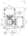
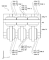
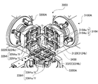
- FIG. 1 is a front view of a mechanism unit 10 of an electrodynamic triaxial vibration device 1 (hereinafter abbreviated as “vibration device 1”) according to a first embodiment of the present invention.
- the left-right direction in FIG. 1 is the X-axis direction (left direction is the X-axis positive direction)
- the up-down direction is the Z-axis direction (upward is the Z-axis positive direction)
- the direction perpendicular to the page is the Y-axis direction
- the direction from the back side to the front side is defined as the Y axis positive direction.
- the Z-axis direction is a vertical direction
- the X-axis and Y-axis directions are horizontal directions.
- 2 and 3 are a left side view and a plan view of the mechanism unit 10 of the vibration exciter 1, respectively.
- the mechanical unit 10 of the vibration exciter 1 includes a substantially box-shaped vibration table 400 that is fixed in a state in which a specimen (not shown) is accommodated therein, and the vibration table 400 as an X-axis.
- Three excitation units X-axis excitation unit 100, Y-axis excitation unit 200, and Z-axis excitation unit 300) that respectively vibrate in the Y-axis and Z-axis directions, and the respective excitation units 100, 200, and 300 Is provided with a device base 500 attached thereto.
- Each excitation unit 100, 200 and 300 is a direct acting excitation unit provided with an electrodynamic actuator (voice coil motor).
- the X-axis vibration unit 100 is coupled to the vibration table 400 via a biaxial slider (YZ slider 160) that is a slide coupling mechanism.
- the YZ slider 160 is a relative movement (sliding) between the X-axis vibration unit 100 and the vibration table 400 in two directions (Y-axis and Z-axis directions) orthogonal to the vibration direction (X-axis direction) of the X-axis vibration unit 100.
- the vibration of the X-axis vibration unit 100 can be accurately transmitted to the vibration table 400.
- the Y-axis vibration unit 200 and the Z-axis vibration unit 300 are connected to the vibration table 400 via a ZX slider 260 and an XY slider 360, which are biaxial sliders, respectively.
- the vibration device 1 vibrates the vibration table 400 and the specimen fixed to the vibration table 400 simultaneously and independently in the three orthogonal axes using the vibration units 100, 200, and 300. Can be done.
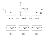
- FIG. 4 is a block diagram showing a schematic configuration of the drive control system 1a of the vibration device 1.
- the drive control system 1a includes a control unit 20 that controls the operation of the entire apparatus, a measurement unit 30 that measures vibrations of the vibration table 400, a power supply unit 40 that supplies power to each unit of the excitation device 1, and an external device.
- An interface unit 50 for performing input / output is provided.
- the interface unit 50 includes, for example, a user interface for inputting / outputting with a user, a network interface for connecting to various networks such as a LAN (Local Area Network), and a USB (Universal Serial for connecting to an external device). Bus) and GPIB (General / Purpose / Interface / Bus).
- the user interface includes, for example, various operation switches, a display, various display devices such as an LCD (liquid crystal display), various pointing devices such as a mouse and a touch pad, a touch screen, a video camera, a printer, a scanner, a buzzer, and a speaker. Including one or more of various input / output devices such as a microphone and a memory card reader / writer.
- the measurement unit 30 includes a three-axis vibration sensor (three-axis vibration pickup) 32 attached to the vibration table 400, and amplifies and digitally converts a signal (for example, an acceleration signal or a speed signal) from the three-axis vibration sensor 32.
- the triaxial vibration sensor 32 independently detects vibrations in the X-axis, Y-axis, and Z-axis directions.
- the measurement unit 30 also determines various parameters (for example, speed, acceleration, jerk, acceleration level (vibration level), amplitude, power spectrum density) indicating the vibration state of the vibration table 400 based on the signal from the triaxial vibration sensor 32. (Including one or more of the following) is transmitted to the control unit 20.
- the control unit 20 Based on the excitation waveform input via the interface unit 50 and the data input from the measurement unit 30, the control unit 20 receives an alternating current input to drive coils (described later) of the excitation units 100, 200, and 300.
- the vibration table 400 can be vibrated with a desired amplitude and frequency by controlling the size and frequency.
- each excitation unit 100, 200 and 300 include electrodynamic actuators for horizontal driving (hereinafter simply referred to as “horizontal actuators”) 100A and 200A, respectively.
- the Z-axis vibration unit 300 includes a vertical drive electrodynamic actuator (hereinafter simply referred to as “vertical actuator”) 300A.
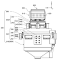
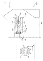
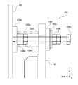
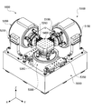
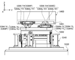
- 6 and 7 are a front view, a left side view and a plan view of the Z-axis vibration unit 300 (and the vibration table 400), respectively.
- the vertical actuator 300A includes an air spring 330 (FIG. 8) for supporting the weight (static load) of the specimen and the vibration table.
- each of the horizontal actuators 100A and 200A includes neutral spring mechanisms 130 (FIG. 11) and 230 (not shown) that provide a restoring force to return the vibration table to the neutral position (origin, reference position).
- the horizontal actuators 100A and 200A except that neutral spring mechanisms 130 and 230 are provided in place of the air spring 330 and that the specific structures of the support unit 350 and the support units 150 and 250 described later are different, Since the configuration is the same as that of the vertical actuator 300A, the detailed configuration of the vertical actuator 300A will be described on behalf of each actuator.
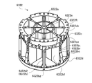
- the vertical actuator 300 ⁇ / b> A includes a fixed portion 310 having a cylindrical body 312 and a movable portion 320 whose lower portion is accommodated in the cylinder of the fixed portion 310.
- the movable part 320 is movable in the vertical direction (Z-axis direction) with respect to the fixed part 310.
- FIG. 9 is an external view showing a schematic configuration of the movable unit 320.
- the movable portion 320 includes a substantially columnar main frame 322, a drive coil 321 coaxially attached to the lower end portion of the main frame 322, and a rod 326 (FIG. 8) extending downward from the center of the lower surface of the main frame. .
- An extension frame 324 having the same diameter as that of the main frame 322 is coaxially attached to the upper end portion of the main frame 322.
- the main frame 322 includes a substantially disk-shaped top plate 322a arranged perpendicular to the drive direction (Z-axis direction), a cylindrical main column 322c extending vertically (drive direction) from the center of the lower surface of the top plate 322a, Eight substantially rectangular flat ribs 322b are provided radially on the outer periphery of the main column 322c.
- the main column 322c and the eight ribs 322b form a substantially cylindrical body portion of the main frame 322.
- the eight ribs 322b are arranged at equal intervals in the circumferential direction around the main pillar 322c.
- the main frame 322 has sufficient rigidity.
- the top plate 322a, the rib 322b, and the main column 322c are integrally coupled to each other by welding or the like.
- the outer peripheral side of the lower end portion of the rib 322b protrudes downward to form a coil attachment portion 322d.
- the coil attachment portions 322d of the eight ribs 322b are inserted into the upper end portion of the drive coil 321, and the drive coil 321 is attached to the main frame 322.
- a rod 326 is fitted into the main pillar 322c from below.
- the lower part of the rod 326 protrudes downward from the main pillar 322c.
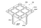
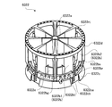
- An extension frame 324 is attached to the top plate 322b.
- FIG. 10 is an external view of the extension frame 324.
- the extension frame 324 includes a trunk portion 324a having substantially the same diameter as the main frame 322, and a top plate 324b attached horizontally to the upper end of the trunk portion 324a.
- the top plate 324b is a substantially rectangular flat plate member having a width (dimension in the X-axis direction) and a depth (dimension in the Y-axis direction) that are equal to or larger than the outer diameter of the body portion 324a.
- the step 324b1 is a positioning structure for attaching the rail 364a to an accurate position on the top plate 324b.
- the nine rails 364a can be arranged on the top plate 324b with high parallelism / verticality simply by attaching the rail 364a along the step 324b1.
- a plurality of screw holes 324b2 for fixing the rail 364a with bolts are formed on the bottom surface of each groove.
- a step 324a1 and a plurality of screw holes 324a2 for positioning and fixing a Z-axis rail 344a of a movable portion support mechanism 340, which will be described later, are formed on both side surfaces in the X-axis direction and the Y-axis direction of the barrel portion 324a. Further, a recess 324a3 is formed on the lower surface of the body 324a. With the top plate 322a of the main frame 322 fitted in the recess 324a3, the expansion frame 324 is fixed to the main frame 322 with bolts.
- a substantially cylindrical inner magnetic pole 316 arranged coaxially with the cylindrical body 312 is fixed inside the cylindrical body 312 of the fixing portion 310. Both the cylindrical body 312 and the inner magnetic pole 316 are made of a magnetic material. The outer diameter of the inner magnetic pole 316 is smaller than the inner diameter of the drive coil 321, and the drive coil 321 is disposed in a gap sandwiched between the outer peripheral surface of the inner magnetic pole 316 and the inner peripheral surface of the cylindrical body 312. A bearing 318 that supports the rod 326 so as to be movable only in the Z-axis direction is fixed in the cylinder of the inner magnetic pole 316.
- a plurality of recesses 312b are formed on the inner peripheral surface 312a of the cylindrical body 312.
- An excitation coil 314 is accommodated in each recess 312b.
- the arrow A extends in the radial direction of the cylindrical body 312 at a location where the inner peripheral surface 312a of the cylindrical body 312 and the outer peripheral surface of the inner magnetic pole 316 approach each other.
- a magnetic field as shown in FIG.
- Lorentz force is generated in the axial direction of the drive coil 321, that is, in the Z-axis direction, and the movable part 320 is driven in the Z-axis direction.
- an air spring 330 is accommodated in the cylinder of the inner magnetic pole 316.
- the lower end of the air spring 330 is fixed to the cylindrical body 312.
- a flange portion formed on the rod 326 is placed on the upper surface of the air spring 330. That is, the air spring 330 supports the main frame 322 from below via the rod 326.
- the movable portion 320, an XY slider 360 supported by the movable portion 320, a vibration table 400, an X-axis counterbalance portion 610, a Y-axis counterbalance portion 620, and a Z-axis counterbalance are supported by the air spring 330.
- the weight (static load) of the part 630 and the specimen is supported.
- the air spring 330 in the Z-axis vibration unit 300 it is necessary to support the weight (static load) of the movable portion 320, the vibration table 400, etc. by the driving force (Lorentz force) of the Z-axis vibration unit 300.
- the drive coil 321 can be reduced in size by reducing the required driving force, the weight of the movable portion 320 can be reduced, so that the Z-axis vibration unit 300 can be driven at a higher frequency.
- the power supply part 40 can also employ a small and simple structure. Become.
- the fixed part 310 when the movable part 320 of the Z-axis excitation unit 300 is driven, the fixed part 310 also receives a large reaction force (excitation force) in the drive axis (Z-axis) direction.
- excitation force a large reaction force
- the air spring 330 between the movable portion 320 and the fixed portion 310, the excitation force transmitted from the movable portion 320 to the fixed portion 310 is reduced. Therefore, for example, the vibration of the movable part 320 is prevented from being transmitted as a noise component to the vibration table 400 via the fixed part 310, the apparatus base 500, and the vibration units 100 and 200.
- the horizontal actuator 100A is different from the vertical actuator 300A in that it includes the neutral spring mechanism 130 (FIG. 11) instead of the air spring 330 (FIG. 8) and the specific structure of the support unit 150. Both are common in the basic configuration.
- the neutral spring mechanism 130 is also a shock absorber that elastically connects the fixed portion 110 and the movable portion 120 of the horizontal actuator 100 ⁇ / b> A, similarly to the air spring 330.
- the horizontal actuator 200A has the same configuration as the horizontal actuator 100A described below.
- FIG. 11 is a longitudinal sectional view of the horizontal actuator 100A, in which the vicinity of the neutral spring mechanism 130 is enlarged.
- the inside of the broken line frame is a rear view of the neutral spring mechanism 130 viewed in the positive direction of the X axis.
- the neutral spring mechanism 130 includes a U-shaped stay 131, a rod 132, a nut 133, and a pair of compression coil springs 134 and 135 (elastic elements).
- the U-shaped stay 131 is fixed to the bottom portion (the right end portion in FIG. 11) of the fixing portion 110 at flange portions 131a formed at both ends of the U-shape.
- a through-hole 131b1 through which a rod 132 extending in the X-axis direction passes is provided at the center of the bottom 131b (the left end in FIG. 11) of the U-shaped stay 131.
- the rod 132 is provided with a flange portion 132b at one end (left end in FIG. 11), and is connected to the tip (right end in FIG. 11) of the rod 126 of the movable portion 120 via the flange portion 132b. Further, the other end portion (the right end portion in FIG. 11) of the rod 132 is formed with a male screw portion 132a into which the nut 133 is fitted.
- the pair of coil springs 134 and 135 are covered with the rod 132.
- One coil spring 134 is sandwiched and held between the flange 133 a of the nut 133 and the bottom 131 b (elastic element support plate) of the U-shaped stay 131.
- the other coil spring 135 is sandwiched and held between the bottom 131b of the U-shaped stay 131 and the flange 132b of the rod 132.
- a preload is applied to the pair of coil springs 134 and 135 by tightening the nut 133.
- the position where the restoring forces of the pair of coil springs 134 and 135 are balanced is the neutral position (or the origin or reference position) in the movable direction (X-axis direction) of the movable portion 120 of the horizontal actuator 100A.
- a restoring force in a direction to return the movable part 120 to the neutral position acts on the movable part 120 by the neutral spring mechanism 130 (directly, a pair of coil springs 134 and 135). Accordingly, the movable unit 120 can always perform reciprocal driving in the X-axis direction with respect to the neutral position, and the problem that the position of the movable unit 120 fluctuates during operation is solved.
- the movable portion 320 of the vertical actuator 300 ⁇ / b> A is movably moved only in the driving direction (Z-axis direction) by four movable portion support mechanisms 340 arranged at equal intervals on the outer periphery thereof. It is supported from the direction.
- the movable part support mechanism 340 of this embodiment includes an angle plate 342 and a Z-axis linear guide 344.
- the Z-axis linear guide 344 includes a Z-axis rail 344a and a Z-axis carriage 344b.
- the Z-axis linear guide 344 has the same configuration as an A-type linear guide 364 / A (FIGS. 14-19) described later.
- the linear guide is a mechanism that guides linear motion, and the Z-axis linear guide 344 guides linear motion in the Z-axis direction.
- Z-axis rails 344a extending in the Z-axis direction of the four sets of movable part support mechanisms 340 are attached to the side surfaces of the body part 324a of the extension frame 324 of the movable part 320 at equal intervals in the circumferential direction.
- the two pairs of movable part support mechanisms 340 are arranged so as to face the X axis direction and the Y axis direction in the horizontal direction forming 45 °, respectively.
- the two pairs of movable portion support mechanisms 340 are illustrated so as to face each other in the X-axis direction and the Y-axis direction.
- the number and arrangement of the movable part support mechanisms 340 are not limited to the configuration of the present embodiment.
- the movable part 320 is composed of three or more sets of movable part support mechanisms 340 arranged at substantially equal intervals around the movable part 320. A configuration that supports the above is desirable.
- angle plates 342 are fixed to the upper surface of the fixing portion 310 (cylindrical body 312) at equal intervals (90 ° intervals) along the inner peripheral surface of the cylindrical body 312.
- the angle plate 342 is a fixing member having a U-shaped (or L-shaped) cross section reinforced with ribs.
- a Z-axis carriage 344b that engages with the Z-axis rail 344a is fixed to the upright portion 342u of each angle plate 342.
- the Z-axis carriage 344b incorporates a large number of balls RE (described later) as rolling elements, and constitutes a Z-axis linear guide 344 as rolling guide together with the Z-axis rail 344a. That is, the movable portion 320 is slidable only in the Z-axis direction from the side by the four sets of support structures (movable portion support mechanism 340) including the angle plate 342 and the Z-axis linear guide 344 in the extension frame 324 on the upper side. It is supported and cannot move in the X-axis and Y-axis directions. Therefore, occurrence of crosstalk due to vibration of the movable part 320 in the X-axis and Y-axis directions is prevented.
- movable portion support mechanism 340 including the angle plate 342 and the Z-axis linear guide 344 in the extension frame 324 on the upper side. It is supported and cannot move in the X-axis and Y-axis directions. Therefore, occurrence of crosstalk due to vibration of the movable part
- the use of the Z-axis linear guide 344 allows the movable portion 320 to move smoothly in the Z-axis direction. Furthermore, as described above, since the movable portion 320 is supported by the bearing 318 so as to be movable only in the Z-axis direction as described above, the rotation about the X-axis, the Y-axis, and the Z-axis is also restricted, which is unnecessary. Vibration (vibration other than controlled translational movement in the Z-axis direction) is difficult to occur.
- the rail is attached to the fixed side and the carriage is attached to the movable side.
- the Z-axis rail 344a is attached to the movable part 320, and the Z-axis carriage 344b is attached to the angle plate 342.
- the resonance frequency of the fixed portion 310 can be made sufficiently higher than the excitation frequency band (for example, 0 to 2000 Hz or more), and a decrease in excitation accuracy due to resonance is suppressed.
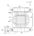
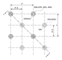
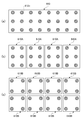
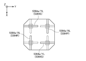
- FIG. 12 is a plan view for explaining the configuration of the XY slider 360.
- the XY slider 360 of this embodiment includes nine cross guides 364 (364L1 to L3, 364M1 to M3, 364R1) arranged at equal intervals in the X axis direction and the Y axis direction. To R3).
- These nine cross guides 364 can slide the Z-axis vibration unit 300 (specifically, the movable portion 320 of the vertical actuator 300A) and the vibration table 400 in the X-axis direction and the Y-axis direction with low resistance. Link.
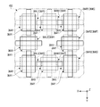
- FIG. 13 is a side view of the cross guide 364.
- the cross guide 364 is an A-type linear guide 364 / A and a B-type linear guide 364 / B that are fixed by overlapping the carriage upper surfaces so that the movable directions are orthogonal to each other.
- the carriages of the A-type linear guide 364 / A and the B-type linear guide 364 / B are formed slightly longer in the traveling direction, the mass distribution in the length (L) direction and the width (W) direction
- the mass distributions of the vibration generators 1 and 2 are different, and this can contribute to the directionality of the vibration performance of the vibration device 1.
- the carriages of the A-type linear guide 364 / A and the B-type linear guide 364 / B are directly fixed so that one length direction is directed to the other width direction, thereby cross carriage (cross guide 364).
- the carriage is formed.
- the directionality of the mass distributions of the A-type linear guide 364 / A and the B-type linear guide 364 / B is considerably canceled out, and a cross carriage with less directionality of the mass distribution is obtained.
- the directionality of the vibration performance of the vibration device 1 is reduced. Details of the A-type linear guide 364 / A and the B-type linear guide 364 / B will be described later.
- the X-axis linear guide 364X is a cross guide 364P (cross guides 364M1, 364L2, 364R2, 364M3) in the first direction attached to the vibration table 400; It can be seen that the second-direction cross guide 364 (cross guides 364L1, 364R1, 364M2, 364L3, 364R3) in which the shaft linear guide 364Y is attached to the vibration table 400 is mixed. In each direction of the X axis direction and the Y axis direction, the directions of the adjacent cross guides 364 are staggered.
- the cross guides 364P in the first direction and the cross guides 364 in the second direction are alternately arranged in each direction of the X axis direction and the Y axis direction. In this way, by arranging the cross guides 364 by alternately changing the directions, the directionality of the mass distribution of the cross guides 364 is averaged, and the excitation performance with less directionality is realized.
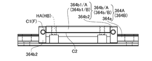
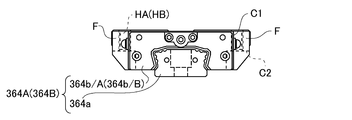
- FIG. 14, FIG. 15, and FIG. 16 are a plan view, a side view, and a front view of an A-type linear guide 364 / A (B-type linear guide 364 / B), respectively.
- the A type linear guide 364 / A (B type linear guide 364 / B) includes a rail 364a and an A type carriage 364b / A (B type carriage 364b / B).
- the A type carriage 364b / A (B type carriage 364b / B) has mounting holes HA (mounting holes HB) which are four screw holes (drilling holes) for fixing bolts at four corners of the upper surface of the carriage. .
- the A type carriage 364b / A and the B type carriage 364b / B have the same structure except for the types of the mounting holes HA and HB.
- the four mounting holes HA and HB are formed so that their center lines pass through the vertices of a square Sq (shown by a chain line in FIG. 14) on the carriage upper surface. That is, the interval at which the attachment hole HA of the A type carriage 364b / A is formed (the length of the side of the square Sq) coincides with the interval at which the attachment hole HB of the B type carriage 364b / B is formed.
- the arrangement of the holes HA and HB has four-fold rotational symmetry.
- the four mounting holes HA and the four mounting holes HB are in communication with each other.
- the A type carriage 364b / A and the B type carriage 364b / B can be connected by the bolts.
- the mounting hole HA of the A type carriage 364b / A is a screw hole and the mounting hole HB of the B type carriage 364b / B is a drilled hole, the A type carriage 364b / A and the B type carriage are not connected via a connecting plate. 364b / B can be directly connected.
- the cross guide 364 can be reduced in size and weight.
- the rigidity of the cross guide 364 is increased (that is, the natural frequency is increased), and the vibration performance of the vibration device 1 is improved. Specifically, excitation with less vibration noise is possible up to a higher frequency.
- the reduction in weight also reduces the power required for exciting the cross guide 364 (that is, driving the mechanism unit 10).
- L-shaped notches C1 are formed at the four corners on the upper surface of the carriage of the A-type carriage 364b / A (B-type carriage 364b / B). Furthermore, a pair of L-shaped notches C2 extending in the traveling direction are formed at the lower portions on both sides in the width direction (vertical direction in FIG. 14) of the A type carriage 364b / A (B type carriage 364b / B). . That is, both end portions in the width direction of the A type carriage 364b / A (B type carriage 364b / B) are scraped off except for the flange portion F protruding from both sides in the width direction where the mounting holes HA (mounting holes HB) are formed. ing. Thereby, the weight reduction of the A type carriage 364b / A (B type carriage 364b / B) is realized.
- the cross guide 364 is composed of only the A-type linear guide 364 / A, the B-type linear guide 364 / B dedicated to the cross guide, and the four bolts connecting them, so that it is small, light, and highly rigid. It has become a thing. As a result, the cross guide 364 has a high resonance frequency and can realize an XY slider (slide coupling mechanism) with less vibration noise.
- the A type carriage 364b / A and the B type carriage 364b / B have the same structure except for the mounting holes HA and HB. Therefore, the mass of each linear guide in the length (L) direction and the width (W) direction is obtained by connecting the A-type linear guide 364 / A and the B-type linear guide 364 / B with the traveling direction shifted from each other by 90 degrees.
- the cross guide 364 is realized in which the directionality of the distribution is offset and the directionality of the mass distribution is small.
- Each of the carriages 364b / A and 364b / B has approximately two-fold rotational symmetry around an axis in the vertical direction (direction perpendicular to the paper surface in FIG. 14), but has four-fold rotational symmetry. Not done. Therefore, each of the carriages 364b / A, 364b / B has different response characteristics with respect to the external force in the traveling direction (left-right direction in FIG. 14) and in the lateral direction (up-down direction in FIG. 14).
- Each of the A type carriage 364b / A and the B type carriage 364b / B having substantially two-fold rotational symmetry and approximately the same mass distribution is rotated by 90 degrees around the vertical axis (rotation symmetry axis).
- the carriage (cross carriage) of the cross guide 364 thus connected has acquired approximately four-fold rotational symmetry and has a more uniform response characteristic to external force between the two traveling directions (X-axis direction and Y-axis direction). It has become.
- the vibration table 400 can move in the X-axis direction with respect to the movable part 320 of the Z-axis vibration unit 300. It is slidably connected in the Y-axis direction.
- each linear guide constituting the cross guide 364 will be described by taking an A-type linear guide 364 / A as an example.
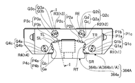
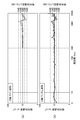
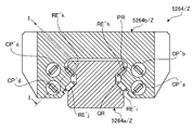
- FIG. 17 is a cross-sectional view of the A-type linear guide 364 / A.
- 18 is a cross-sectional view taken along the line II of FIG.
- the outer diameter of the ball RE which is a rolling element
- the number of load paths of the rolling element is set to eight, which is twice the normal number.
- the number of balls RE the number of effective balls
- the load is distributed to the number of balls RE that is twice or more the normal number of balls RE, so that the load per ball RE is halved and the rigidity of the linear guide is remarkably improved.
- by increasing the number of effective balls more uniform rolling guidance is possible, and as a result, the movement accuracy of the carriage is improved (specifically, the posture change and vibration of the carriage that occur during travel are reduced). Yes.
- the A type carriage 364b / A includes a main block 364b1 / A, a pair of end blocks 364b2 attached to both ends of the main block 364b1 / A in the traveling direction, and four columnar shapes penetrating the main block 364b1 / A in the traveling direction.
- the rod members R1, R2, R3, and R4 of the present embodiment are members having the same configuration.
- the main block 364b1 / A is a metal member (for example, stainless steel), and the end block 364b2 and the rod members R1, R2, R3, and R4 are resin members.
- the material of each member constituting the A-type carriage 364b / A is not limited to that of the present embodiment, and is appropriately selected from metal, resin, ceramics, various composite materials (for example, fiber reinforced plastic), and the like.
- two grooves Ga extending in the length direction are formed adjacent to each other on both side surfaces (the right side surface SR and the left side surface SL) of the rail 364a. Also, two grooves Ga extending in the length direction are formed adjacent to each other on the left and right portions (the right upper surface TR and the left upper surface TL) of the upper surface of the rail 364a.
- route means the part to which a load is added to a rolling element among the paths of a rolling element.
- the load paths Pa1 and Pb1 are formed close to each other between the right side surface SR of the rail 364a and the main block 364b1 / A.
- the load paths Pa2 and Pb2 are formed close to each other between the right upper surface TR of the rail 364a and the main block 364b1 / A.
- the load paths Pa3 and Pb3 are formed close to each other between the left upper surface TL of the rail 364a and the main block 364b1 / A.
- the load paths Pa4 and Pb4 are formed close to each other between the left side surface SL of the rail 364a and the main block 364b1 / A.
- Such a pair of rolling element paths formed close to each other in parallel is hereinafter referred to as a “path pair”.
- gaps Gs1, Gs2, Gs3, and Gs4 are formed between the right side SR, right upper surface TR, left upper surface TL, left side SL, and main block 364b1 / A of the rail 364a, respectively.
- the load path pairs P1, P2, P3, and P4 are formed in the gaps Pc1, Pc2, Pc3, and Pc4, respectively.
- the four through holes h1, h2, h3, h4 are formed in parallel to positions facing the four load path pairs P1, P2, P3, P4.
- through holes Qc (Qc1, Qc2, Qc3, and Qc4) having a substantially rectangular cross section penetrate each in the length direction.
- Qc On the inner peripheral surface of each through hole Qc (specifically, two surfaces facing each other at a narrow interval), two opposing pairs of grooves Gc and Ge extending in the extending direction of the through hole Qc (only the through hole Qc2 is indicated)
- the no-load paths Qa Qa1, Qa2, Qa3, Qa4) and Qb (Qb1, Qb2, Qb3, Qb4) are formed respectively.
- U-shaped protruding portions Rp3 protruding from the through holes h3 of the main block 364b1 / A are provided at both ends of the rod member R3.
- the pair of parallel grooves Gcu described above are formed on the outer peripheral surface of each protrusion Rp3.
- the other rod members R1, R2, and R4 are also provided with protrusions Rp1, Rp2, and Rp4 (not shown) each having a pair of U-shaped grooves Gc.
- the end block 364b2 is formed with four recesses D1, D2, D3, D4 (only the recess D3 is shown) that accommodates the protrusions Rp (Rp1, Rp2, Rp3, Rp4).
- a pair of grooves Ge that are opposed to the pair of grooves Gcu formed in the protrusion Rp3 are formed.
- Two U-shaped folded paths Ua3 and Ub3 (only the path Ua3 is shown) are constituted by the two pairs of grooves Gc and Ge facing each other.
- a pair of grooves Ge is formed in the other three recesses D1, D2, and D4, and a pair of grooves Gc formed in the corresponding protrusions Rp1, Rp2, and Rp4, respectively.
- the return paths Ua1 and Ub1, Ua2 and Ub2, and Ua4 and Ub4 are configured.
- gaps Gu1, Gu2, Gu3, Gu4 are formed between the protrusions Rp1, Rp2, Rp3, Rp4 and the recesses D1, D2, D3, D4, respectively.
- the return paths Ua1 and Ub1, Ua2 and Ub2, Ua3 and Ub3, and Ua4 and Ub4 are formed in gaps Gu1, Gu2, Gu3, and Gu4, respectively.
- the folding paths Ua and Ub have one end connected to the load paths Pa and Pb and the other end connected to the no-load paths Qa and Qb, respectively. That is, eight pairs of load paths Pa1, Pb1, Pa2, Pb2, Pa3, Pb3, Pa4, Pb4 and eight no-load paths Qa1, Qb1, Qa2, Qb2, Qa3, Qb3, Qa4, Qb4. Are connected in a ring shape by the loop-back paths Ua1, Ub1, Ua2, Ub2, Ua3, Ub3, Ua4, Ub4 to form an eight-way circulation path.
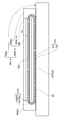
- the gap Gs (Gs1, Gs2, Gs3, Gs4) and the through hole Qc (Qc1, Qc2, Qc3, Qc4) are annularly formed by a pair of U-shaped gaps Gu (Gu1, Gu2, Gu3, Gu4). Connected, four annular gaps CG are formed. In the four annular gaps CG, the four pairs (eight) of circulation paths CP are respectively formed.
- each of the eight circulation paths CP a large number of stainless steel balls RE (rolling elements) are accommodated in a line. Further, one endless belt-like retainer RT is passed through each of the four annular gaps CG.
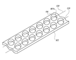
- FIG. 19 is a perspective view showing a part of the retainer RT.
- the retainer RT is a resin member having flexibility, and a large number of through holes RTh are formed in two rows at regular intervals in the length direction. The interval between the two rows of the through holes RTh is the same as the two circulation paths CP (path pairs) provided in each annular gap CG.
- a large number of balls RE arranged in a path pair in the same annular gap CG are fitted in the two rows of through holes RTh of the retainer RT so as to be rotatable.
- the retainer RT circulates in the annular gap CG together with a large number of balls RE.
- the retainer RT prevents contact between the balls RE, and reduces vibration noise and wear of the balls RE due to friction between the balls RE.
- the A type carriage 364b / A (and the B type carriage 364b / B) of this embodiment has an aspect ratio (length L, width W, and length L of 125 mm or less (about 120 mm)). Ratio L / W) is suppressed to 1.35 or less (about 1.32).
- the length L of the eight-row type carriage used for the vibration device is preferably in the range of 70-160 mm (more preferably in the range of 90-140 mm, still more preferably in the range of 110-130 mm). .
- the aspect ratio L / W should be close to 1 in order to make the vibration performance in each axis direction uniform.
- the aspect ratio L / W of the eight-row carriage as in this embodiment is in the range of 0.65-1.5 (more preferably in the range of 0.7-1.4, still more preferably 0.8. 75 to 1.35).
- the X-axis vibration unit 100 and the Y-axis are connected. Even if the vibration table 400 is vibrated in the X-axis direction and the Y-axis direction by the vibration unit 200, vibration components in the X-axis direction and the Y-axis direction of the vibration table 400 can be transmitted to the Z-axis vibration unit 300. Absent.
- the A-type linear guide 364 / A of the present embodiment reduces the outer diameter of the ball RE to about half of the normal diameter, thereby reducing the number of the circulation path CP to twice the normal number. It is an article. Further, the number of balls RE arranged in each load path is also increased to nearly twice the normal number. As a result, the A-type carriage 364b / A is supported in a more dispersed manner by the number of balls RE that is twice or more (nearly four times) the number of balls. As a result, improved rigidity and improved running accuracy (low waving) have been realized.
- the conventional 8-row linear guide such as the A-type linear guide 364 / A has been limited to use for the purpose of improving the positional accuracy in a machine tool or the like
- the conventional 8-row linear guide is The carriage length L was as large as 180 mm or more, and the aspect ratio was 2.3 or more and the weight balance was low.
- the conventional 8-row linear guide is not suitable for a mechanism that performs high-speed driving such as a vibration device.
- the A-type linear guide 364 / A (B-type linear guide 364 / B) of the present embodiment can be applied to a vibration device by reducing the carriage length L and the aspect ratio. It has become a thing. Further, by using the A-type linear guide 364 / A, it has become possible to vibrate at a frequency exceeding 2 kHz, which has been difficult in the past.
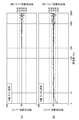
- FIG. 20 is a side view of the X-axis vibration unit 100 and the vibration table 400.
- FIG. 21 is a front view of the X-axis vibration unit 100.
- FIG. 22 is a front view of the YZ slider 160.
- FIG. 23 is a plan view of the vicinity of the vibration table 400.
- the YZ slider 160 connects the connecting arm 162 fixed to the distal end surface of the movable portion 120 (expansion frame 124) of the X-axis excitation unit 100, the connecting arm 162, and the vibration table 400 to the Y-axis. And a cross guide portion 164 slidably coupled in the direction and the Z-axis direction.
- the cross guide portion 164 includes two Y-axis rails 164a / Y (164a / Y1, 164a / Y4) and six Z-axis rails 164a / Z (164a / Z1, 164a / Z2). 164a / Z3, 164a / Z4, 164a / Z5, 164a / Z6), and six crosses that slidably connect the Y-axis rail 164a / Y and the Z-axis rail 164a / Z in the Y-axis and Z-axis directions.
- a carriage 164b (164b / 1, 164b / 2, 164b / 3, 164b / 4, 164b / 5, 164b / 6) is provided.
- the six cross carriages 164b are arranged in a lattice shape (Y-axis direction: 3 rows, Z-axis direction: 2 rows).
- the upper three Z-axis rails 164a / Z1, 164a / Z2, 164a / Z3 and the lower Y-axis rail 164a / Y4 are fixed to the distal end surface of the connecting arm 162.
- the remaining three lower Z-axis rails 164 a / Z 4, / Z 5, / Z 6 and one upper Y-axis rail 164 a / Y 1 are fixed to the side surface of the vibration table 400.
- the cross carriage 164b / 1 has a Y-axis carriage 164b / Y1 that engages with the Y-axis rail 164a / Y1 and a Z-axis carriage 164b / Z1 that engages with the Z-axis rail 164a / Z1 stacked back to back (that is, It is fixed by superimposing the upper surfaces of the carriages.
- One of the Y-axis carriage 164b / Y1 and the Z-axis carriage 164b / Z1 has the same configuration as the above-described A-type carriage 364b / A, and the other has the same configuration as the above-described B-type carriage 364b / B.
- the Y-axis carriage 164b / Y1 and the Z-axis carriage 164b / Z1 are directly fixed by only four bolts without using an attachment plate.
- the upper three cross carriages 164b / 1, 164b / 2, 164b / 3 are all engaged with the upper Y-axis rail 164a / Y1, and the upper three Z-axis rails 164a / It is engaged with Z1, 164a / Z2, 164a / Z3, respectively.
- the lower three cross carriages 164b / 4, 164b / 5, 164b / 6 are all engaged with the lower Y-axis rail 164a / Y4, and the lower three Z-axis
- the rails 164a / Z4, 164a / Z5, and 164a / Z6 are engaged with each other.
- the vibration table 400 is connected to the movable portion 120 of the X-axis vibration unit 100 so as to be slidable in the Y-axis direction and the Z-axis direction.
- the Y-axis vibration unit 200 and the Z-axis vibration unit are connected. Even if the vibration table 400 is vibrated in the Y-axis direction and the Z-axis direction by the vibration unit 300, vibration components in the Y-axis direction and the Z-axis direction of the vibration table 400 are not transmitted to the X-axis vibration unit 100. .
- the ZX slider 260 that connects the Y-axis vibration unit 200 and the vibration table 400 also has the same configuration as the YZ slider 160, and the vibration table 400 is connected to the movable part 220 of the Y-axis vibration unit 200. On the other hand, it is slidably connected in the Z-axis direction and the X-axis direction. Therefore, even if the vibration table 400 is vibrated in the Z-axis direction and the X-axis direction by the Z-axis vibration unit 300 and the X-axis vibration unit 100, the vibration components in the Z-axis direction and the X-axis direction of the vibration table 400 are not changed. There is no transmission to the Y-axis vibration unit 200.
- each of the vibration units 100, 200, and 300 can accurately vibrate the vibration table 400 in each driving direction without interfering with each other.
- each of the excitation units 100, 200, and 300 is supported so that the movable portion can move only in the drive direction by the movable portion support mechanism, it is difficult to vibrate in the non-drive direction. Therefore, uncontrolled vibration in the non-driving direction is not applied to the vibration table 400 from each of the vibration units 100, 200, and 300. Therefore, the vibration in each axial direction of the vibration table 400 is accurately controlled by driving the corresponding excitation units 100, 200, and 300.
- the vibration table 400 is configured such that the center of gravity substantially coincides with the center position of the outer dimensions in order to suppress the occurrence of unnecessary rotational motion (rotational vibration).
- a biaxial slider YZ slider 160, ZX slider 260, XY slider 360
- a part of the biaxial slider is fixed to the vibration table 400 (more accurately). Therefore, the center of gravity of the portion to be excited (the vibration table 400 and a part of the biaxial slider) deviates from the center of the vibration table 400.
- the deviation of the center of gravity of the excited portion induces rotational vibration of the vibration table 400, and as a result, variation in vibration state (for example, acceleration) depending on the position on the vibration table 400 occurs.
- a counter balance unit that compensates for the unbalance caused by the biaxial slider is provided in the vibration table 400, and the excited portion (vibration table 400, counter balance unit and 2) is provided.
- the center of gravity of a part of the shaft slider is configured to substantially coincide with the center position of the vibration table 400.
- the X-axis counterbalance is provided on the side surface of the vibration table 400 opposite to the side surface to which the YZ slider 160 is attached (that is, the side surface on the X-axis positive direction side).
- a unit 610 (first counter balance unit) is provided.
- a Y-axis counter balance unit 620 (second counter balance unit) is provided on the side surface of the vibration table 400 opposite to the side surface to which the ZX slider 260 is attached (that is, the side surface on the Y axis positive direction side). ing. Note that the Y-axis counterbalance unit 620 of the present embodiment has the same configuration as the X-axis counterbalance unit 610.
- a Z-axis counter balance unit 630 (third counter balance unit) is provided on the upper surface (that is, the side surface on the Z axis positive direction side) opposite to the lower surface to which the XY slider 360 of the vibration table 400 is attached. Yes.
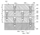
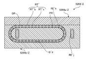
- FIG. 25 is a cross-sectional view of the X-axis counterbalance unit 610 (and the Y-axis counterbalance unit 620).
- the X-axis counterbalance unit 610 includes a buffer layer 611 (buffer unit) and a weight plate 612 (weight unit).
- the buffer layer 611 is sandwiched between the weight plate 612 and the side surface of the vibration table 400 and tightened.
- the weight plate 612 is a member that gives a mass to compensate for the unbalance of the excited portion that occurs when the biaxial slider is attached to the vibration table 400.
- the thickness of the weight plate 612 of this embodiment is 20 mm.
- the buffer layer 611 blocks transmission of vibration noise having a frequency component higher than the excitation frequency between the weight plate 612 and the vibration table 400. Further, the buffer layer 611 prevents chattering from occurring between the vibration table 400 and the weight plate 612.
- the weight plate 612 and the buffer layer 611 are attached to the side surface of the vibration table 400 with a plurality of bolts 613.
- a screw hole 400 h is formed on the side surface of the vibration table 400, and a through hole 612 c is formed in the weight plate 612.
- the weight plate 612 and the buffer layer 611 are fastened to the side surface of the vibration table 400 by passing the bolt 613 through the through hole 612c and screwing it into the screw hole 400h.
- the buffer layer 611 also has a through hole communicating with the through hole 612c and the screw hole 400h.
- a plurality of through holes 612c are formed in lattice points at equal intervals P in two orthogonal directions (Y-axis direction and Z-axis direction). .
- the interval P between the through holes 612c is 50 mm.
- FIG. 26 is a cross-sectional view of the Z-axis counterbalance unit 630.
- FIG. 27 is an enlarged plan view showing a bolt fixing position of the Z-axis counterbalance unit 630.
- 26 is a cross-sectional view taken along the line JJ in FIG.
- the Z-axis counterbalance portion 630 includes a first buffer layer 631 (first buffer portion), a first weight plate 632 (first weight portion), a second buffer layer 634 (second buffer portion), and a second weight plate 635 ( A second weight portion), a third buffer layer 637 (third buffer portion), and a third weight plate 638 (third weight portion).
- the first buffer layer 631, the first weight plate 632, the second buffer layer 634, the second weight plate 635, the third buffer layer 637, and the third weight plate 638 are stacked on the upper surface of the vibration table 400 in this order. .
- the first weight plate 632, the second weight plate 635, and the third weight plate 638 are members that give mass to compensate for the unbalance of the excited portion that occurs when the biaxial slider is attached to the vibration table 400.
- it is an aluminum alloy plate.
- the thicknesses of the first weight plate 632, the second weight plate 635, and the third weight plate 638 are 30 mm, 20 mm, and 10 mm, respectively.
- the width (X-axis direction) and depth (Y-axis direction) of the vibration table 400 of this embodiment are each 500 mm
- the width and depth of the Z-axis counterbalance unit 630 are each about 400 mm.
- the first buffer layer 631, the second buffer layer 634, and the third buffer layer 637 are respectively determined by excitation frequencies between the first weight plate 632 and the vibration table 400 or between the adjacent weight plates 632, 635, and 638. Also reduce the transmission of vibration noise of high frequency components.
- the first buffer layer 631, the second buffer layer 634, and the third buffer layer 637 are used for chatter vibration between the vibration table 400 and the first weight plate 632 or between the adjacent weight plates 632, 635, and 638. Prevent occurrence.
- a plurality of through holes 632c and a plurality of screw holes 632t are respectively equidistantly arranged in two orthogonal directions (X-axis direction and Y-axis direction) in the form of lattice points (in this embodiment, the X-axis counterbalance). It is formed at the same interval P) as the through hole 612c of the portion 610. As shown in FIG. 27, the positions of the through holes 632c and the screw holes 632t are shifted by P / 2 in each arrangement direction. That is, a screw hole 632t is formed at an intermediate position between the four through holes 632c in plan view.
- the bolt 633 is passed through the through hole 632 c and screwed into the screw hole 400 h formed on the upper surface of the vibration table 400, whereby the weight plate 632 and the first buffer layer 631 are tightened on the upper surface of the vibration table 400.
- a plurality of through holes 635c and a plurality of screw holes 635t are formed at equal intervals P in two orthogonal directions (X-axis direction and Y-axis direction) in lattice points.
- the positions of the through hole 635c and the screw hole 635t are shifted by P / 2 in each arrangement direction.
- the bolt 636 is passed through the through hole 635 c and screwed into the screw hole 632 t formed on the upper surface of the first weight plate 632, so that the second weight plate 635 and the second buffer layer 634 are placed on the upper surface of the first weight plate 632. Tightened to.
- the bolt 639 is passed through the through hole 638 c and screwed into the screw hole 635 t formed on the upper surface of the second weight plate 635, so that the third weight plate 638 and the third buffer layer 637 become the upper surface of the second weight plate 635. Tightened to.
- the Z-axis counterbalance unit 630 has a configuration in which three weight plates and buffer layers are stacked, so that vibration noise can be effectively suppressed even when a heavy specimen is placed thereon. It is possible.
- the three weight plates and the buffer layer are not directly fixed (jointly fastened) to the vibration table 400 with one bolt, but adjacent weight plates (first weight plate 632 and second weight plate 635, By adopting a configuration in which the two weight plate 635 and the third weight plate 638) are sequentially and individually fixed with bolts, transmission of vibration noise from the vibration table 400 to the third weight plate 638 is effectively suppressed.
- each of the weight plates 612, 632, 635, and 638 is not limited to a rectangular flat plate shape, and can be formed in various shapes. For example, by making the shape corresponding to the shape (mass distribution) of the biaxial slider, it becomes possible to compensate for imbalance with high accuracy.
- each of the weight plates 632, 635, 638 may be changed according to the weight of the specimen, the vibration conditions, and the like.
- the weight plates 632, 635, and 638 may all have the same thickness.
- the upper weight plate may be thicker, or the intermediate weight plate 635 may be thickest.
- weight plates 612, 632, 635, 638 in addition to general structural materials such as aluminum alloy and steel, lead, copper, foam metal, resin (plastic, rubber, etc.) having vibration absorption properties are used. A fiber reinforced resin, etc.).
- each buffer layer 611, 631, 634, 637 is determined within a range of 0.5 mm to 2 mm according to the mass of the weight plate, the material and characteristics of the buffer layer, the size of the vibrating device 1, the test conditions, and the like. Is done. If the buffer layer is too thick, the weight plate is likely to resonate, and the excitation performance in the low frequency region is degraded. If the buffer layer is too thin, the effect of suppressing vibration noise cannot be obtained sufficiently.
- various synthetic resins for example, polyolefins, polyvinyl chloride, polyamide, PEEK (polyether ether ketone), polycarbonate, polytetrafluoroethylene, etc.
- various elastomers natural rubber
- vulcanized rubber such as various synthetic rubbers, thermosetting elastomers such as urethane rubber and silicone rubber, thermoplastic elastomers), silicone gel (low crosslink density silicone resin), various polymer alloys, fiber reinforced plastic, foamed resin, lead, etc.
- Sheets or felts (nonwoven fabrics) of various materials such as soft metals and foamed metals can be used.
- the gap is filled with an adhesive or a caulking material and cured.
- a buffer layer may be formed.
- the Z-axis counterbalance unit 630 of the present embodiment is formed by alternately stacking three layers of buffer layers and weight plates, but may be configured by stacking two layers or four or more layers. Moreover, you may change the material and thickness of a buffer layer or a weight board for every layer.
- FIG. 28-30 is a graph showing the spectral characteristics of the relative acceleration measured at four locations on the vibration table 400 (more precisely, the Z-axis counterbalance unit 630).
- FIG. 31 is a diagram showing monitoring points (acceleration measurement points) on the Z-axis counterbalance unit 630.
- the vibration exciter 1 is designed so that the reference point MP0, which is the center of the upper surface of the Z-axis counterbalance unit 630, vibrates at the same acceleration as the indicated value (that is, performs one-point control based on the measured acceleration value at the reference point MP0).
- vibration is controlled based on measurement results of parameters representing vibration states such as acceleration at two or more of the five monitoring points including the reference point MP0 (for example, average values of measured values at a plurality of monitoring points). It is good also as a structure which performs multipoint control.
- the vibration uniformity of the vibration exciter 1 is the relative acceleration level in the four corner regions (monitor points MP1, MP2, MP3, MP4) of the Z-axis counterbalance unit 630 that is considered to have the largest difference in acceleration from the reference point MP0. Evaluation was made by measuring La.
- the relative acceleration level La is a relative acceleration level at each of the monitoring points MP1 to MP4 with respect to the acceleration at the reference point MP0, and is defined by the following Equation 1.
- La relative acceleration level a at each monitoring point: acceleration at the reference point MP 0: acceleration a 0 at each monitoring point (MP1 ⁇ MP4)
- the monitoring points MP1, MP2, MP3, and MP4 are located at the center of the four corners of the four corners of the 16 regions obtained by dividing the upper surface of the Z-axis counterbalance unit 630 into a lattice shape.
- FIGS. 28, 29, and 30 are graphs showing measurement results in the X-axis direction, the Y-axis direction, and the Z-axis direction, respectively.
- the upper part (a) of each figure shows the measurement result when the sine waveform is vibrated, and the lower part (b) shows the measurement result when the random waveform is vibrated.
- the sine waveform was measured in the frequency range of 200-2000 Hz, and the random waveform was measured in the range of 5-2000 Hz.
- the relative acceleration level was suppressed to less than ⁇ 3 dB in the frequency region of 1 kHz or less under any condition.
- the relative acceleration level is suppressed to less than ⁇ 6 dB except for some measurement conditions, and the relative acceleration level is suppressed to less than ⁇ 10 dB in all measurement conditions.
- the relative acceleration level exceeds ⁇ 10 dB under any measurement condition in the frequency range of 2 kHz or less, and it is confirmed that the excitation uniformity is significantly improved by attaching the counter balance part. It was.
- FIG. 32 is a cross-sectional view of a first modification 610A of the X-axis counterbalance unit 610.
- a spacer 611a for example, a flat washer
- the buffer layer 611 is used instead of the buffer layer 611.
- a gap is provided between the weight plate 612 and the vibration table 400, and the weight plate 612 is held in non-contact with the vibration table 400. Therefore, it is difficult for vibration to be transmitted between the vibration table 400 and the weight plate 612. Further, chatter vibration is prevented from occurring between the vibration table 400 and the weight plate 612.
- the spacer 611a may be made of various steels such as stainless steel, aluminum alloys, copper alloys such as brass, various nonferrous metals such as titanium alloys, and materials usable for the buffer layer 611 described above.
- the spacer 611a may be formed as a boss-shaped protrusion integrally with the vibration table 400 or the weight plate 612.
- a filler eg, silicone resin
- silicone resin may be filled in the gap between the vibration table 400 and the weight plate 612.
- buffer layers 631, 634, 637 of the Z-axis counterbalance unit 630 may be changed to the spacer 611a.
- FIG. 33 is an external view of the X-axis counterbalance unit.
- (A) shows the X-axis counterbalance part 610 of 1st Embodiment
- (b) and (c) show the 2nd modification 610B and the 3rd modification 610C, respectively.
- the X-axis counterbalance unit 610 of the first embodiment is formed as a single body from one weight plate 612 (and one buffer layer 611).
- the weight plate 612 and the buffer layer 611 are divided into four in the length direction (left-right direction in the figure).
- the weight plate 612 and the buffer layer 611 are further divided into two in the width direction (vertical direction in the figure), for a total of eight.
- the resonance frequency is increased and the generation of vibration noise in the test frequency region is reduced.
- the configuration of the first modification 610A may be applied to the second modification 610B and the third modification 610C.
- the X-axis counterbalance unit 610, the Y-axis counterbalance unit 620, and the Z-axis counterbalance unit 630 are all attached to the outer surface of the vibration table 400, but one or more of these are attached to the vibration table 400. You may attach to the inside.
- the vibration table 400 itself has no unbalance, but the vibration table 400 can be balanced with the biaxial slider mounted (the center of gravity of the vibration table matches the center of the outer shape).
- An initial unbalance may be given in advance.
- the initial unbalance can be imparted, for example, by making the thickness of the box-shaped vibration table or the arrangement of the reinforcing ribs inside the vibration table non-uniform.
- the fixed portion 310 of the Z-axis vibration unit 300 includes a pair of support units 350 (fixed portion support) disposed on both sides of the Z-axis vibration unit 300 in the Y-axis direction. It is also attached to the upper surface of the apparatus base 500 via a mechanism, a floating mechanism, or an elastic support mechanism.
- each support unit 350 includes a movable block 358, a pair of angle plates (fixed blocks) 352, and a pair of linear guides 354.
- the movable block 358 is a support member fixed to the side surface of the fixed portion 310 of the Z-axis vibration unit 300.
- the pair of angle plates 352 are disposed to face both end surfaces in the X-axis direction of the movable block 358 and are fixed to the upper surface of the apparatus base 500. Both ends of the movable block 358 in the X-axis direction and each angle plate 352 are connected by linear guides 354 so as to be slidable in the Z-axis direction.
- the linear guide 354 includes a rail 354a and a carriage 354b that engages with the rail 354a.
- Rails 354 a are attached to both end surfaces in the X-axis direction of the movable block 358.
- Each angle plate 352 is provided with a carriage 354b that engages with an opposing rail 354a.
- a pair of air springs 356 are arranged in the X-axis direction between the movable block 358 and the apparatus base 500, and the movable block 358 is supported by the apparatus base 500 via the pair of air springs 356. Yes.
- the Z-axis vibration unit 300 is elastically supported in the driving direction (Z-axis direction) with respect to the apparatus base 500 by the support unit 350 whose fixed portion 310 includes the linear guide 354 and the air spring 356. Therefore, a strong reaction force (excitation force) in the Z-axis direction applied to the fixed portion 310 when the Z-axis excitation unit 300 is driven is not directly transmitted to the apparatus base 500, and a particularly high frequency component is generated by the air spring 356. It is greatly attenuated. Therefore, vibration noise transmitted from the Z-axis vibration unit 300 to the vibration table 400 via the apparatus base 500 and the other vibration units 100 and 200 is greatly reduced.
- each support unit 150 includes an inverted T-shaped fixed block 152 fixed to the upper surface of the apparatus base 500, a substantially rectangular parallelepiped movable block 158 attached to the side surface of the fixed portion 110 of the X-axis vibration unit 100, A linear guide 154 that slidably connects the fixed block 152 and the movable block 158 in the X-axis direction, and a spring mechanism 156 that elastically connects the movable block 158 and the fixed block 152 are provided.
- the linear guide 154 includes a rail 154a extending in the X-axis direction attached to the upper surface of the fixed block 152 and a pair of carriages 154b engaged with the rail 154a attached to the lower surface of the movable block 158. Further, an L-shaped arm 155 extending upward is fixed to the side surface of the fixed block 152 on the X axis negative direction side. The movable block 158 and the arm 155 are connected by a spring mechanism 156.
- FIG. 24 is an enlarged side view of the vicinity of the spring mechanism 156 of the support unit 150.
- the spring mechanism 156 includes a bolt 156a, a fixing plate 156b, a ring 156c, a nut 156d, an anti-vibration spring 156e, a buffer plate 156f, a washer 156g, and a nut 156h.
- a through hole 155h extending in the X-axis direction is provided in the upper portion of the arm 155, and a bolt 156a is passed through the through hole 155h.
- the tip of the bolt 156a is fixed to the movable block 158 via a fixed plate 156b.
- bolt 156a has penetrated the cylindrical ring 156c.
- the ring 156c is sandwiched and fixed between a nut 156d screwed into the bolt 156a and the fixing plate 156b. Further, the front end side of the bolt 156a is inserted into a hollow portion of a cylindrical vibration-proof spring 156e. The anti-vibration spring 156e is sandwiched and held between the fixed plate 156b and the arm 155. A ring 156c is fitted into one end of the hollow portion of the vibration-proof spring 156e.
- the anti-vibration spring 156e is a cylindrical member in which a steel compression coil spring is embedded in a viscoelastic body (damper) such as acrylic resin.
- a single coil spring may be used instead of the vibration-proof spring 156e.
- a separate damper for example, an anti-vibration rubber or an oil damper may be provided in series or in parallel with the coil spring.
- the buffer plate 156f is made of, for example, a resin such as an anti-vibration rubber or polyurethane (that is, a rubber elastic body and / or a viscoelastic body).
- a preload compresses the vibration-proof spring 156e and the buffer plate 156f.
- the horizontal actuator 100A fixed to the movable block 158 is held at a neutral position where the restoring forces of the anti-vibration spring 156e and the buffer plate 156f are balanced. That is, the spring mechanism 156 also functions as a neutral spring mechanism.
- the reaction force is transmitted to the movable block 158 of the support unit 150, and further, the spring mechanism 156 (vibration isolation spring 156e, buffer plate 156f) and arm 155. Is transmitted to the fixed block 152 via. Since the vibration-proof spring 156e and the buffer plate 156f attenuate vibrations having a frequency higher than the low resonance frequency, transmission of vibration noise from the X-axis vibration unit 100 to the apparatus base 500 is suppressed by the support unit 150.
- the reaction force in the positive X-axis direction applied to the support unit 150 is smaller than the reaction force in the negative X-axis direction. Therefore, in the present embodiment, a small and inexpensive buffer plate 156f is used as an elastic element that receives a reaction force in the X-axis positive direction.
- an anti-vibration spring or a coil spring may be used instead of the buffer plate 156f. If the reaction force in any direction is low, a buffer plate may be used instead of the vibration-proof spring 156e.
- the fixed portion 110 of the X-axis vibration unit 100 is soft and elastic in the driving direction (X-axis direction) with respect to the apparatus base 500 by the support unit 150 including the linear guide 154 and the spring mechanism 156. Therefore, a strong reaction force (excitation force) in the X-axis direction applied to the fixed portion 110 when the X-axis excitation unit 100 is driven is not directly transmitted to the apparatus base 500, and particularly a high-frequency component is generated by the spring mechanism 156. After being attenuated, it is transmitted to the device base 500. Therefore, vibration noise transmitted from the X-axis vibration unit 100 to the vibration table 400 is reduced.
- the Y-axis vibration unit 200 also includes a horizontal actuator 200A having the same configuration as the horizontal actuator 100A.
- the fixed portion 210 of the horizontal actuator 200A is also elastically supported by the device base 500 in the Y-axis direction by a pair of support units 250 (FIG. 2). Since the support unit 250 has the same configuration as that of the support unit 150 of the X-axis vibration unit 100, the description of the overlapping details is omitted.
- each excitation unit 100, 200, 300 is elastically supported by the support units 150, 250, 350 having an elastic element (air spring or spring mechanism), the apparatus base Since the transmission of vibration (noise) of particularly high frequency components between the excitation units via 500 is suppressed, more accurate excitation is possible.
- the support unit 350 that supports the Z-axis vibration unit 300 includes the weight of the Z-axis vibration unit 300, the vibration table 400, and the specimen. (Static load) is applied. Therefore, an air spring 356 that is relatively small and capable of supporting a large load is employed. On the other hand, since a large static load is not applied to the support unit 150 that supports the X-axis vibration unit 100 and the support unit 250 that supports the Y-axis vibration unit 200, coil springs that are relatively small in size and simple in configuration are provided. in use.
- the rotational vibration of the vibration table 400 is reduced by using a low-waving 8-row linear guide for the biaxial sliders (YZ slider 160, ZX slider 260, XY slider 360) that greatly affect the vibration performance.
- the uniformity of the vibration state (acceleration) on the vibration table 400 is remarkably improved.
- this improved uniformity makes it possible to define the vibration performance specifications over a wide area on the vibration table. It became possible.
- the center of gravity of the excited part (including part of the vibration table and the biaxial slider) is set to the center of the vibration table.
- the variation in vibration (acceleration) on the vibration table can be reduced to 3 dB or less in the frequency region up to 1 kHz and to approximately 6 dB or less in the frequency region up to 2 kHz.
- FIG. 34 is a plan view illustrating a configuration of a modification 360A of the XY slider.
- the second-direction cross guide 364M2 disposed in the center is removed from the XY slider 360 of the first embodiment (FIG. 12) described above.
- the X-axis linear guide 364X has a first-direction cross guide 364P (cross guides 364M1, 364L2, 364R2, 364M3) attached to the vibration table 400, and the Y-axis linear guide 364Y.
- the number of second-direction cross guides 364S cross guides 364L1, 364R1, 364L3, 364R3 attached to the vibration table 400 is the same.
- FIG. 35A is a front view of the cross guide 364P in the first direction
- FIG. 35B is a left side view thereof.
- the X-axis linear guide 364X (X-axis rail 364a / X) is attached to the vibration table 400 in the first direction.
- the cross guide 364P only the X-axis rail 364a / X (solid line) fixed to the vibration table 400 is vibrated in the X-axis direction together with the vibration table 400, and the cross carriage 364c and the Y-axis rail 364a / Y (broken line) are No vibration is applied in the X-axis direction.
- the vibration is contrary to the first-direction cross guide 364P described above.
- the Y-axis rail 364a / Y and the cross carriage 364c solid line
- the X-axis rail 364a / X broken line
- Table 1 organizes the relationship between the mounting direction of the cross guide 364 and the vibration direction of the vibration table 400 and the vibration-excited portion of the cross guide 364 (components of the cross guide 364 that are vibrated together with the vibration table 400). It is a thing.
- the portion of the cross guide 364 that is vibrated together with the vibration table 400 differs depending on the direction of vibration and the mounting direction.
- the vibration table 400 is vibrated in the X-axis direction, as described above, in the first-direction cross guide 364P, only the X-axis rail 364a / X is vibrated in the X-axis direction.
- the Y-axis rail 364a / Y and the cross carriage 364c are vibrated in the X-axis direction.
- the relationship between the vibration direction and the number of elements of the cross-excited portion of the cross guide 364 is that the cross guide 364P in the first direction and the cross guide 364S in the second direction It becomes the opposite.
- the vibration table 400 is vibrated in the X axis direction and the Y axis direction.
- the mass of the portion to be vibrated of the cross guide 364 changes when it is vibrated. Thereby, directionality arises in the vibration performance of the vibration apparatus 1.
- the cross guide 364 of the cross guide 364 can be vibrated in any of the X-axis and Y-axis directions. Since the total mass of the excited parts is constant, the directionality of the excitation performance is reduced.
- the XY slider 360A of the present modified example configured by the four pairs of the first-direction cross guide 364P and the second-direction cross guide 364S has the second-direction cross guide 364S in the first-direction cross.
- the portion to be vibrated is reduced in weight and can be excited at a higher frequency.
- substantially the entire side surface (right side surface in FIG. 1) on the X-axis negative direction side of the vibration table 400 is formed by a slide coupling mechanism 160 (specifically, a plurality of slide coupling mechanisms 160 are provided).
- the linear guide way) and the movable portion 120 of the X-axis vibration unit 100 are supported substantially evenly.
- the entire side surface of the vibration table 400 on the X axis negative direction side is configured to be able to receive a substantially uniform excitation force by the X axis excitation unit 100.
- substantially the entire surface of the vibration table 400 on the Y axis negative direction side (the left side surface in FIG. 2) is substantially uniformly supported by the slide coupling mechanism 260 and the movable portion 220 of the Y axis excitation unit 200.
- the entire side surface of the vibration table 400 on the Y axis negative direction side is configured to receive a substantially uniform excitation force by the Y axis excitation unit 200.
- substantially the entire lower surface of the vibration table 400 is formed by a slide coupling mechanism 360 (specifically, a plurality of linear guideways provided in the slide coupling mechanism 360) and a Z-axis excitation.
- the movable part 320 of the unit 300 is supported substantially evenly.
- the entire lower surface of the vibration table 400 is configured to receive a substantially uniform excitation force by the Z-axis excitation unit 300.
- the vibration table 400 according to the present embodiment is configured to be able to vibrate the vibration object in a state where the vibration object is accommodated therein.
- the vibration table 400 includes a box part 400a having an opening on the upper surface, and a lid part 400b that closes the opening of the box part 400a.
- FIG. 36 shows a state where the lid 400b is removed.
- the lid portion 400b is detachably attached to the box portion 400a by a bolt (not shown) that fits a female screw 421 provided on the upper surface of the box portion 400a (more specifically, a frame portion 420 described later). ing.
- the vibration table 400 is configured such that its center of gravity is located at the approximate center of the outer shape.
- the box portion 400a includes a bottom plate 450 and a frame portion (wall portion) 420 protruding vertically upward from the periphery of the bottom plate 450. As shown in FIG. 36, the bottom plate 450 is formed in a shape in which four corners of a square are cut off.
- middle plates 430 and 440 parallel to each wall surface (excluding the corner cutting part) of the frame part 420 are provided in a lattice shape.
- the middle plate 430 extends in the Y-axis direction (left-right direction in FIG. 36), and the middle plate 440 extends in the X-axis direction (up-down direction in FIG. 36).
- the middle plates 430 and 440 are joined to the bottom plate 450 and the frame portion 420 at one end (or both ends) thereof.
- an accommodation space S that is a hollow portion in which the intermediate plates (wall portions) 430 and 440 are not formed is provided.
- the excited object is accommodated in the accommodation space S.
- Thick plate portions 431 and 441 that are thicker than the other portions are provided at the center in the extending direction (horizontal direction) of the middle plates 430a and 440a that partition the housing space S, respectively.
- the thick plate portions 431 and 441 are formed with through holes 432 and 442 through which the bolt B for fixing the object to be excited is passed, respectively.
- the attachment component 460 for attaching the vibrating object T1 to the vibration table 400 is fixed to the middle plates 440a on both the left and right sides by bolts B that are passed through the through holes 432.
- the vibrating object T1 is disposed in the approximate center of the accommodation space S. As a result, the center of gravity of the shaker T1 is positioned near the center of the vibration table 400.
- the vibration table 400 of the present embodiment can vibrate a vibration target having a rotation shaft (for example, a power transmission device such as an engine, a motor, and a differential gear) with the rotation shaft rotated. It is configured.
- the excited object T1 (and the excited object T2 to be described later) of the present embodiment is a generator for a hybrid vehicle.
- an opening 422 is formed on the left side surface of the frame 420 for passing the driving belt DB for transmitting power.
- the left middle plate 440 also has an opening 443 for passing the driving belt DB at a position facing the opening 422.
- the driving belt DB is stretched between a driving pulley (not shown) of an external driving device and a driven pulley FP attached to the vibration target T1, and the vibration table 400 is externally applied during vibration.
- the driven object T1 can be vibrated while applying a driving force to the inner excited object T1 and rotating the excited object T1.
- a pipe for supplying hydraulic pressure or pneumatic pressure to the excited object T1 a power cable for supplying power, an external information processing apparatus and Other types of long objects that connect the object to be excited T1 and an external device such as a communication cable that connects the object to be excited (or a sensor or measurement device attached to the object to be shaken) so as to communicate with the opening 422 and 443 can also be passed.
- an opening for passing these pipes and cables may be provided in the vibration table 400.
- the driving object is connected to the object to be measured and an external measuring device by the driving belt DB, and the power generated by the object to be excited while exciting the object to be excited. Can also be measured.
- the bottom plate 450 of the vibration table 400 is provided with a plurality of female screws 451 for fixing the object to be excited.
- FIG. 39 is a left side view of the vibration table 400 in a state in which the vibration target T2 having a fixing through hole is attached to the bottom.
- the bolt B passed through the through hole for fixing the vibration target T2 is screwed into the female screw 451, so that the vibration target T2 is fixed to the bottom plate 450 of the vibration table 400.
- the excited object T2 is also attached to the approximate center of the accommodation space S.
- the center of gravity of the vibrating object T2 is positioned near the center of the vibration table 400.
- the vibration target T2 is directly fixed to the bottom plate 450 of the vibration table 400.
- the vibration target T2 is attached via a spacer or the like. It may be fixed to the bottom plate 450 so that the center of gravity of the vibration target T2 is positioned at the center of the vibration table 400.
- the center of gravity of the object to be excited is high, for example, the object to be excited may be fixed to the lid portion 400b and the object to be excited T2 may be attached to the vibration table 400 upside down.
- the excited object and the vibration table 400 are vibrated in a state where the excited object is accommodated in the vibration table 400.
- the center of gravity of all the vibration parts is always arranged in the vibration table 400. Therefore, the generation of the moment of force of all the vibration parts is prevented. It becomes possible to reduce it reliably.
- the vibration table 400 of the above embodiment is configured in a box shape with a lid, the center of gravity of all the excited parts is within the vibration table 400 (more precisely, A space in which the movable portion 320 [slide coupling mechanism 360] of the Z-axis vibration unit 300 is extended in the Z-axis direction, and a space in which the movable portion 122 [slide coupling mechanism 160] of the X-axis vibration unit 100 is extended in the X-axis direction.
- the projection of the center of gravity of all the excited parts on the XY plane perpendicular to the Z axis is included in the projection of the movable part 320 (slide coupling mechanism 360) of the Z axis exciting unit 300 on the XY plane.
- the projection of the center of gravity of all the excited parts on the YZ plane perpendicular to the X axis is included in the projection of the movable part 122 (slide coupling mechanism 160) of the X axis excitation unit 100 on the YZ plane. It only has to be configured. For example, it is good also as a structure which has only the surface to which the slide connection mechanism 160 of the frame part 420 is attached, and the baseplate 450 to which the Z-axis vibration unit 300 is attached.
- the storage space S (the middle plates 430 a and 440 a that partition the storage space S) is provided at the center of the vibration table 400, so that the center of gravity of the object to be vibrated is more reliably brought closer to the center of the vibration table 400. Is possible.
- the second embodiment is different from the first embodiment only in the configuration of the biaxial slider (slide coupling mechanism).
- the description will mainly focus on the differences from the first embodiment, and the description of the configuration common to the first embodiment will be omitted.
- FIG. 40 is an enlarged perspective view (partially perspective view) of the vicinity of the vibration table 2400 of the vibration exciter 2000 according to the second embodiment of the present invention.
- the vibration table 2400 shows only the contour line by a two-dot chain line.
- illustration of each counter balance part is abbreviate
- Each biaxial slider (YZ slider 2160, ZX slider 2260, XY slider 2360) of this embodiment is arranged in a lattice shape (3 rows and 3 columns) at equal intervals similarly to the XY slider 360 of the first embodiment. It consists of nine cross guides 2164, 2264, 2364. The cross guides 2164, 2264, and 2364 have the same configuration as the cross guide 364 of the XY slider 360 of the first embodiment.
- the XY slider 2360 of the present embodiment has the same configuration as the XY slider 360 (FIG. 12) of the first embodiment. That is, any two cross guides 2364 adjacent in the X-axis direction or the Y-axis direction are disposed in the opposite directions in the vertical direction (Z-axis direction). That is, one X-axis rail 2364a / X of any two cross guides 2364 adjacent in the X-axis direction or the Y-axis direction is fixed to the distal end surface (top plate 2324b) of the movable portion 2320, and the other X-axis rail 2364a. / X is fixed to the lower surface of the vibration table 2400. With this arrangement, the directionality of the mass distribution and motion characteristics of the individual cross guides 2364 is averaged, and an excitation performance with less directionality (or directionality spots) can be obtained.
- the cross guide 2164 of the YZ slider 2160 and the cross guide 2264 of the ZX slider 2260 are also the same as the cross guide 364 (first direction cross guide 364P, second direction cross guide 364S). ) Is adopted.
- one Y-axis rail 2164a / Y of any two cross guides 2164 adjacent in the Y-axis direction or the Z-axis direction is on the tip surface (top plate 2124b) of the movable portion 2120.
- the other Y-axis rail 2164a / Y is fixed to the side surface of the vibration table 2400.
- one X-axis rail 2264a / X of any two cross guides 2264 adjacent in the Z-axis direction or the X-axis direction is fixed to the distal end surface (top plate 2224b) of the movable portion 2220.
- the other X-axis rail 2264a / X is fixed to the side surface of the vibration table 2400.
- each surface of the vibration table 2400 is uniformly vibrated by the same configuration as the XY slider 2360 described above. For this reason, uniform vibration can be achieved with less uneven vibration throughout the entire vibration table 2400.
- the vibration table 2400 is vibrated through the biaxial sliders (YZ slider 2160, ZX slider 2260, XY slider 2360) having the same configuration, so that vibration with less directivity can be performed.
- the vibration table 2400 When the vibration table 2400 has a short height, 2 of the nine cross guides 2164 and 2264 arranged in 3 rows and 3 columns of the second embodiment except for the uppermost or lowermost three.
- the YZ slider 2160 and the ZX slider 2260 may be configured by six cross guides 2164 and 2264 arranged in three rows and columns.
- the same number of cross guides in the first direction and cross guides in the second direction are alternately arranged in the two orthogonal directions. The directionality is reduced, and each part of the vibration table 2400 can be more uniformly vibrated.
- FIG. 41 is an enlarged perspective view (partially perspective view) of the vicinity of the vibration table 3400 of the vibration exciter 3000 according to the third embodiment of the present invention.
- the vibration table 3400 shows only the contour line with a two-dot chain line.
- illustration of each counter balance part is abbreviate
- the arrangement configuration of the cross guides 364 (the first-direction cross guide 364P and the second-direction cross guide 364S) in the above-described XY slider modification 360A (FIG. 34) is changed to each biaxial slider ( YZ slider 3160, ZX slider 3260, and XY slider 3360).
- the YZ slider 3160 and the ZX slider 3260 of this embodiment are used to connect the vibration table 400 and the horizontal actuators 3100A and 3200A with more cross guides 3164 and 3264 than the YZ slider 160 and the ZX slider 260 of the first embodiment.
- the vibration table 400 can be vibrated more uniformly.
- the YZ slider 3160 and the ZX slider 3260 of the present embodiment have a configuration in which the same number of first-direction cross guides and second-direction cross guides are alternately arranged, as in the modification 360A (FIG. 34). Therefore, the directivity of the vibration performance is reduced, and each part of the vibration table 3400 can be more evenly excited.
- the fourth embodiment differs from the first embodiment described above only in the configuration of the biaxial slider (slide coupling mechanism). In the following description of the fourth embodiment, differences from the first embodiment will be mainly described, and description of components common to the first embodiment will be omitted.
- a cross carriage is used by using connection plates 4164c, 4264c, and 4364c to connect the linear guides. It differs from the configuration of the first embodiment in that the rigidity of the part is increased.
- the YZ slider 4160 of this embodiment includes three Y-axis linear guides 4164 / Y (Y-axis rail 4164a / Y and Y-axis carriage 4164b / Y) and five Z-axis linear guides. 4164 / Z (Z-axis rail 4164a / Z and Z-axis carriage 4164b / Z) and a connecting plate 4164c for connecting all Y-axis linear guides 4164 / Y and Z-axis linear guides 4164 / Z.
- the Y-axis carriage 4164b / Y and the Z-axis carriage 4164b / Z are eight-row carriages like the A-type carriage 364b / A of the first embodiment, but unlike the A-type carriage 364b / A, they have a low aspect ratio. There is no reduction in weight (shortening) or weight reduction by forming the notches C1 and C2.
- the A-type carriage 364b / A may be used as the Y-axis carriage 4164b / Y and the Z-axis carriage 4164b / Z. Further, the same carriage as the Y-axis carriage 4164b / Y (Z-axis carriage 4164b / Z) may be used instead of the A-type carriage 364b / A in other embodiments.
- the Y-axis linear guide 4164 / Y includes one Y-axis rail 4164a / Y and two Y-axis carriages 4164b / Y.
- the Y-axis carriage 4164b / Y of the three Y-axis linear guides 4164 / Y are arranged in the Z-axis direction with almost no gap and are fixed to the front end surface of the connecting arm 4162.
- the Y-axis rail 4164a / Y is fixed to one surface of the connecting plate 4164c. Note that three Y-axis linear guides 4164 / Y may be arranged at intervals in the Z-axis direction.
- the interval between the Y-axis linear guides 4164 / Y be narrower than the width of the Y-axis carriage 4164b / Y (size in the Z-axis direction).
- the Y-axis carriage 4164b / Y having a large mass is attached to the connecting arm 4162 that is vibrated only in the X-axis direction instead of the connecting plate 4164c that is vibrated in the biaxial (X-axis, Y-axis) directions. Vibration performance is improved.
- the mass distribution of the Y-axis rail 4164a / Y is uniform in the Y-axis direction, vibrations caused by fluctuations in the weight distribution are small when the Y-axis rail 4164a / Y is vibrated in the Y-axis direction. Therefore, by attaching the Y-axis rail 4164a / Y to the connecting plate 4164c that is vibrated in the Y-axis direction, generation of vibration noise is reduced.
- the Z-axis linear guide 4164 / Z is composed of one Z-axis rail 4164a / Z and one Z-axis carriage 4164b / Z.
- the Z-axis carriages 4164b / Z of the five Z-axis linear guides 4164 / Z are arranged with substantially no gap in the Y-axis direction and fixed to the other surface of the connecting plate 4164c.
- the Z-axis rail 4164a / Z is fixed to the side surface of the vibration table 4400.
- three Z-axis linear guides 4164 / Z may be arranged at intervals in the Y-axis direction. In this case, in order to give sufficient rigidity to the YZ slider 4160, it is desirable that the interval between the Z-axis linear guides 4164 / Z be narrower than the width of the Z-axis carriage 4164b / Z (size in the Y-axis direction).
- three Y-axis linear guides 4164 / Y are arranged without gaps in the Z-axis direction.
- three Z-axis linear guides 4164 / Z are also arranged without gaps in the Y-axis direction.
- all the Y-axis rails 4164a / Y and the Z-axis carriage 4164b / Z are directly fixed to a sufficiently rigid connecting plate 4164c.
- the Z-axis carriage 4164b / Z having a large mass is vibrated only in the two-axis (X-axis, Y-axis) direction, not the vibration table 4400 that is vibrated in the three-axis (X-axis, Y-axis, Z-axis) directions.
- the connecting plate 4164c By attaching to the connecting plate 4164c, the excitation performance is enhanced.
- the generation of vibration noise is reduced by attaching the Z-axis rail 4164a / Z to the vibration table 4400 which is vibrated in the Z-axis direction.
- a plurality of Y-axis rails 4164a / Y are spread over substantially the entire surface of one surface of the connecting plate 4164c.
- the connecting plate 4164c is vibrated in the X-axis direction via a plurality of Y-axis rails 4164a / Y that uniformly cover one surface of the connecting plate 4164c. Therefore, the entire connection plate 4164c is uniformly excited in the X-axis direction.
- the excitation force transmitted from each Y-axis linear guide 4164 / Y is averaged by the connection plate 4164c having high rigidity, and is applied to the vibration table 4400 via the Z-axis linear guide 4164 / Z as a more uniform excitation force. Communicated.
- a plurality of Z-axis rails 4164a / Z are spread over substantially the entire surface of the vibration table 4400 facing the movable portion 120 of the X-axis excitation unit.
- the vibration table 4400 is vibrated in the X-axis direction via a plurality of Z-axis rails 4164a / Z that uniformly cover the side surfaces. Therefore, the entire vibration table 4400 is evenly excited in the X-axis direction, and uniform vibration with less acceleration and jerk of the acceleration within the vibration table 4400 is possible.
- the XY slider 4360 of this embodiment includes three X-axis linear guides 4364 / X (an X-axis rail 4364a / X and an X-axis carriage 4364b / X) and three Y-axis linear guides. 4364 / Y (Y-axis rail 4364a / Y and Y-axis carriage 4364b / Y), and a connecting plate 4364c for connecting all X-axis linear guides 4364 / X and Y-axis linear guides 4364 / Y.
- the X-axis carriage 4364b / X and the Y-axis carriage 4364b / Y have the same configuration as the Y-axis carriage 4164b / Y and the Z-axis carriage 4164b / Z.
- the X-axis linear guide 4364 / X includes one X-axis rail 4364a / X and two X-axis carriages 4364b / X.
- the X-axis rails 4364a / X of the three X-axis linear guides 4364 / X are arranged at equal intervals in the Y-axis direction, and the front end surface of the movable part 320 of the Z-axis vibration unit 300 It is fixed to.
- the X-axis carriage 4364b / X is fixed to the lower surface of the connecting plate 4364c.
- the Y-axis linear guide 4364 / Y is also composed of one Y-axis rail 4364a / Y and two Y-axis carriages 4364b / Y.
- the Y-axis rails 4364a / Y of the three Y-axis linear guides 4364 / Y are arranged at equal intervals in the X-axis direction and fixed to the upper surface of the connecting plate 4364c.
- the Y-axis carriage 4364a / Z is fixed to the lower surface of the vibration table 4400.
- the three X-axis linear guides 4364 / X are arranged at an interval narrower than the width (size in the Y-axis direction) of the X-axis carriage 4364b / X.
- the three Y-axis linear guides 4364 / Y are also arranged at an interval narrower than the width (size in the X-axis direction) of the Y-axis carriage 4364b / Y.
- all the X-axis carriages 4364b / X and the Y-axis rails 4364a / Y are directly fixed to a sufficiently rigid connecting plate 4364c.
- the rigidity of the XY slider 4360 (particularly, the connecting portion in which the connecting plate 4364c, the X-axis carriage 4364b / X and the Y-axis rail 4364a / Y are integrally fixed) is increased, and the resonance frequency is increased.
- the X-axis linear guide 4364 / X and the Y-axis linear guide 4364 / Y of the XY slider 4360 are arranged with an interval, but the Y-axis linear guide 4164 / Y and Z of the YZ slider 4160 are arranged.
- the X-axis linear guide 4364 / X and the Y-axis linear guide 4364 / Y may be arranged without substantial gaps.
- connection plates 4364c, 4264c, and 4364c of the present embodiment are made of stainless steel, but when higher frequency excitation performance is required, aluminum alloys such as duralumin, magnesium alloys, carbon fiber composite materials
- the inertia of the biaxial slider may be reduced by using a light structural material such as
- FIG. 45 is an external view of a vibration exciter 5000 according to the fifth embodiment of the present invention.
- the fifth embodiment is different from the first embodiment in the configuration of the linear guide used in the biaxial slider (slide coupling mechanism), the movable portion support mechanism, and the fixed portion support mechanism, and the configuration of the biaxial slider.
- differences from the first embodiment will be mainly described, and description of components common to the first embodiment will be omitted.
- FIG. 46 is a view showing the tip of the Y-axis vibration unit 5200 to which the ZX slider 5260 is attached.
- the ZX slider 5260 includes two Z-axis rails 5264a / Z, four Z-axis carriages 5264b / Z, four X-axis carriages 5264b / X, two X-axis rails 5264a / X, and a connecting arm 5262.
- the connection arm 5262 is a support member fixed to the top plate 5224 b of the extension frame 5224.
- the two Z-axis rails 5264a / Z extending in the Z-axis direction are arranged at a predetermined interval in the X-axis direction and are fixed to the connecting arm 5262.
- Each Z-axis rail 5264a / Z is equipped with two Z-axis carriages 5264b / Z that are slidably engaged therewith.
- each X-axis rail 5264a / X is equipped with two X-axis carriages 5264b / X that are slidably engaged therewith.
- Each Z-axis carriage 5264b / Z is fixed integrally with a bolt in a state where one of the X-axis carriages 5264b / X and the upper surface of the carriage are overlapped to form a cross carriage 5264.
- the pair of Z-axis rails 5264a / Z and the pair of X-axis rails 5264a / X are arranged in a cross beam shape, and are connected by a cross carriage 5264 at positions where they cross each other.
- the movable portion 5220 of the Y-axis vibration unit 5200 and the vibration table 5400 are coupled to be slidable in both the X-axis and Z-axis directions.
- the ZX sliders 5260 of the present embodiment are arranged at intervals in the width direction (X-axis direction in the Z-axis rail 5264a / Z and Z-axis direction in the X-axis rail 5264a / X).
- Each pair includes a Z-axis rail 5264a / Z and an X-axis rail 5264a / X.
- the arrangement interval of each rail pair is as wide as possible.
- the interval between the X-axis rails 5264a / X is limited by the height of the vibration table 5400. Therefore, one X-axis rail 5264a / X is attached to the upper end portion of the side surface of the vibration table 5400, and the other X-axis rail 5264a / X is attached to the upper end portion of the side surface of the vibration table 5400.
- the arrangement interval of the Z-axis rails 5264a / Z is limited by the diameter of the movable portion 5220 (top plate 5224b) of the Y-axis vibration unit 5200. Therefore, as shown in FIG.
- the distance between the pair of Z-axis rails 5264a / Z is such that each Z-axis rail 5264a / Z does not come out of the cylindrical surface extending the outer peripheral surface of the movable portion 5220 in the Y-axis direction.
- the maximum interval in the range is such that each Z-axis rail 5264a / Z does not come out of the cylindrical surface extending the outer peripheral surface of the movable portion 5220 in the Y-axis direction.
- the other linear guides used in the vibration exciter 5000 also have the same structure as the Z-axis linear guide 5264 / Z.
- FIG. 48 is a longitudinal cross-sectional view of the Z-axis rail 5264a / Z and the Z-axis carriage 5264b / Z of the ZX slider 5260 cut along a plane perpendicular to the major axis of the Z-axis rail 5264a / Z (that is, the XY plane).
- FIG. 49 is a view taken along the line II of FIG.
- the Z-axis linear guide 5264 / Z of this embodiment uses a roller as a rolling element. By using a roller as a rolling element, high positional accuracy and rigidity can be obtained. A linear guide using balls as rolling elements can also be used.
- a groove GR having a trapezoidal cross section extending in the Z-axis direction is formed on both side surfaces in the Y-axis direction of the Z-axis rail 5264a / Z in FIG.
- a groove GR extending in the Z-axis direction is formed in the Z-axis carriage 5264b / Z so as to surround the Z-axis rail 5264a / Z.
- Projections PR extending along the groove GR of the Z-axis rail 5264a / Z are formed on the side walls of the groove GR.
- the protrusion PR is formed with a pair of slopes parallel to the slopes of the trapezoidal groove GR of the Z-axis rail 5264a / Z.
- a gap is formed between each of the four slopes of the pair of grooves GR and the slope of the protruding portion PR facing each other.
- a number of stainless steel rollers RE ′ (RE′h, RE′i, RE′j, RE′k) and a resin retainer for rotatably holding and connecting the rollers are provided.
- RT ' is stored.
- the rollers RE ′ are sandwiched and held between the inclined surface of the groove GR and the inclined surface of the protruding portion PR, respectively.
- the carriage can be supported by a large number of rollers and the rollers RE ′ (RE′h, RE′i, RE′j, RE′k ) Roll, the resistance in the Z-axis direction is kept small, and the Z-axis carriage 5264b / Z can be smoothly moved with respect to the Z-axis rail 5264a / Z.
- a retainer RT ′ that connects a plurality of rollers connects a plurality of spacer portions RTs ′ arranged between the rollers RE′k and a plurality of spacer portions RTs ′.
- Each roller RE′k is held in a space surrounded by a pair of adjacent spacer portions RTs ′ and a pair of bands RTb ′.
- the Y-axis vibration unit 5200 and the vibration table 5400 via the ZX slider 5260 that can slide with very small frictional resistance in the X-axis direction and the Z-axis direction, the X-axis vibration unit 5100 and Even if the vibration table 5400 is vibrated in the X-axis direction and the Z-axis direction by the Z-axis vibration unit 5300, vibration components in the X-axis direction and the Z-axis direction of the vibration table 5400 are transmitted to the Y-axis vibration unit 5200. There is no. Further, since the vibration table 5400 receives almost no force in the Z-axis direction and the X-axis direction by driving the Y-axis vibration unit 5200, vibration with less crosstalk becomes possible.
- the YZ slider 5160 that connects the X-axis vibration unit 5100 and the vibration table 5400 also has the same configuration as the ZX slider 5260, and the vibration table 5400 is relative to the movable part of the X-axis vibration unit 5100.
- FIG. 47 is a side view of the vicinity of the XY slider 5360.
- FIG. FIG. 50 is a view for explaining the arrangement of rails of the XY slider 5360 attached to the top plate 5324bb of the movable portion 5320 of the Z-axis vibration unit 5300.
- the XY slider 5360 includes four cross guides 364.
- the cross guide 364 (364P, 364S) includes one X-axis linear guide 5364 / X (5364 / XL, 5364 / XH) and one Y-axis linear guide 5364 / Y (5364 / YH, 5364 / YL). ing.
- the X-axis linear guide 5364 / X includes one X-axis rail 5364a / X (5364a / XL, 5364a / XH) and one X-axis carriage 5364b / X (5364b / XL, 5364b / XH).
- the linear guide 5364 / Y includes one Y-axis rail 5364a / Y (5364a / YH, 5364a / YL) and one Y-axis carriage 5364b / Y (5364b / YH, 5364b / YL).
- the X-axis carriage 5364b / X and the Y-axis carriage 5364b / Y are integrally fixed with bolts with the carriage upper surfaces being overlapped to form a cross carriage.
- This cross carriage has the same configuration as the cross carriage 5264 of the ZX slider 5260 described above.
- the cross guide 364 includes a cross guide 364P in the first direction in which the X-axis linear guide 5364 / X is attached to the vibration table 5400 and a second direction in which the Y-axis linear guide 5364 / Y is attached to the vibration table 5400. And a cross guide 364S.
- the X-axis rail 5364a / XL of the cross guide 364P is attached to the upper surface of the top plate 5324b, and the Y-axis rail 5364a / YH is attached to the lower surface of the vibration table 5400.
- each cross guide 364 connects the movable portion 5320 of the Z-axis vibration unit 5300 and the vibration table 5400 so as to be slidable in the X-axis direction and the Y-axis direction.
- the X-axis linear guide 5364 / X and the Y-axis linear guide 5364 / Y attached to the top plate 5324b are respectively connected to the low-order X-axis linear guide 5364 / XL (low-order X-axis rail 5364a / XL, low-order X-axis carriage 5364b / XL) and low-order Y-axis linear guide 5364 / YL (low-order Y-axis rail 5364a / YL, low-order Y-axis carriage 5364b / YL).
- the X-axis linear guide 5364 / X and the Y-axis linear guide 5364 / Y attached to the vibration table 5400 are respectively replaced with a high-order X-axis linear guide 5364 / XH (high-order X-axis rail 5364a / XH, high-order X-axis carriage 5364b / XH) and high-order Y-axis linear guide 5364 / YH (high-order Y-axis rail 5364a / YH, high-order Y-axis carriage 5364b / YH).
- the four cross guides 364 are attached to the four corners of the upper surface of the substantially square top plate 5324b. Further, the cross guides 364P and 364S are alternately arranged around the central axis Ax of the Z-axis vibration unit 5300. That is, the arrangement of the cross guides 364P and 364S has a four-fold rotational symmetry around the central axis Ax. With the arrangement of the cross guide 5364, the mass distribution around the central axis Ax of the XY slider 5360 is leveled. As a result, the response characteristics of the XY slider 5360 with respect to vibrations in the X-axis direction and the Y-axis direction are more uniform.
- the X-axis carriage 5364b / X and the Y-axis carriage 5364b / Y have different types of mounting holes (the X-axis carriage 5364b / X has four through holes, and the Y-axis carriage 5364b / Y has four screws. Except for the formation of holes, they have the same structure. Also, the X-axis rail 5364a / X and the Y-axis rail 5364a / Y are the same. Each linear guide (X-axis linear guide 5364 / X, Y-axis linear guide 5364 / Y) has a different mass distribution in the X-axis direction and the Y-axis direction.
- the mass distribution in the X-axis direction and the Y-axis direction is leveled. Also with this configuration, the response characteristics of the XY slider 5360 with respect to vibrations in the X-axis direction and the Y-axis direction are more uniform.
- Each excitation unit (X-axis excitation unit 5100, Y-axis excitation unit 5200, Z-axis excitation unit 5300) is a device via a pair of support units 5150, 210, 310 (fixed portion support mechanism), respectively. Attached to the base 5500.
- the support units 5150, 210, and 310 are shock absorbers that include elastic elements (coil springs or air springs) that elastically support the vibration units 5100, 5200, and 5300, and are provided in the vibration direction of the vibration units. Transmission of vibrations (particularly high frequency components) to the device base 5500 is suppressed.
- vibration units 5100, 5200, and 5300 By attaching the vibration units 5100, 5200, and 5300 to the apparatus base 5500 via the support units 5150, 5250, and 5350, transmission of vibration between the vibration units 5100, 5200, and 5300 is suppressed, and crosstalk is small. More accurate three-axis excitation is possible.
- the sixth embodiment differs from the first embodiment in the frame structure of the movable part of each electrodynamic actuator (each horizontal actuator in the X-axis direction and Y-axis direction, the vertical actuator 6300A).
- each electrodynamic actuator each horizontal actuator in the X-axis direction and Y-axis direction, the vertical actuator 6300A.
- the description will mainly focus on the differences from the first embodiment, and description of configurations common to the first embodiment will be omitted.
- FIG. 51 shows an electrodynamic triaxial vibration device 6000 (Z-axis vibration unit 6300, vibration table 400, X-axis counterbalance unit 610, Y-axis counterbalance unit 620, and Z-axis according to the sixth embodiment of the present invention. It is a front view of only the counter balance part 630.).
- the movable portion 6320 of the vertical actuator 6300A of the sixth embodiment includes a frame 6322. *
- 52 and 53 are perspective views showing the appearance of the frame 6322, respectively.
- 52 is a view of the frame 6322 as seen from the front side (vibration table 400 side)
- FIG. 53 is a view as seen from the back side.
- the frame 6322 is formed in a substantially cylindrical shape having a central axis extending in the driving direction (Z-axis direction) as a whole.
- the frame 6322 of this embodiment is formed by casting and cutting aluminum alloy, but the material and processing method of the frame 6322 are not limited to this.
- the frame 6322 may be formed of other metal materials such as stainless steel, titanium alloy, and magnesium alloy, or resin materials such as glass fiber reinforced resin (GFRP) and carbon fiber reinforced resin (CFRP).
- GFRP glass fiber reinforced resin
- CFRP carbon fiber reinforced resin
- the frame 6322 may be integrally formed by welding, welding, adhesion, injection molding, three-dimensional modeling (3D printer), or the like.
- the frame 6322 includes a substantially cylindrical main pillar 6322a extending in the driving direction, eight plate-like ribs 6322b (6322b1, 6322b2) extending radially from the outer peripheral surface of the main pillar 6322a, and eight ribs 6322b on the front side.
- An annular front peripheral edge 6322c that connects the front ends of the two ribs
- a substantially annular rear peripheral edge 6322d that connects the front ends of the eight ribs 6322b on the back side
- a cylindrical intermediate connecting portion 6322e that connects intermediate portions in the (radial direction) is provided.
- a rod 326 (see FIG. 8) is fitted into the main pillar 6322a from below.
- both high rigidity and light weight of the frame 6322 can be achieved. Further, by providing the intermediate coupling portion 6322e, the base plate 6362 can be supported more uniformly (in a plane).
- a plurality of tap holes 6322ft for attaching the base plate 6362 are formed on the front surface of the frame 6322 (specifically, the rib 6322b, the front peripheral edge portion 6322c, and the intermediate connection portion 6322e).
- a plurality of screw holes 6322rt for attaching the drive coil 321 are formed on the back surface of the frame 6322 (specifically, the back peripheral edge portion 6322d).
- a row of screw holes 6322bt for attaching the Z-axis rail 344a of the movable portion support mechanism 340 is formed on the end surface (outer peripheral surface) of the four ribs 6322b1 of the eight ribs 6322b. Further, fitting grooves 6322bg for fitting with the coil attachment portions 322d are formed on the end surfaces of the remaining four ribs 6322b2. The ribs 6322b1 and the ribs 6322b2 are alternately arranged in the circumferential direction.
- a concave portion 6322ca is formed in the vicinity of the rib 6322b so as not to interfere with the Z-axis carriage 344b of the movable portion support mechanism 340.
- a step 6322cb for positioning the Z-axis rail 344a in the horizontal direction is formed along the row of the holes 6322bt.
- the end surface of the rib 6322b1 also has a rail mounting surface 6322br formed by offsetting the front side portion to which the Z-axis rail 344a is mounted to the main pillar 6322a side to the same depth as the bottom surface of the recess 6322ca. Further, a step 6322bs for positioning the Z-axis rail 344a in the vertical direction is formed on the end surface of the rib 6322b1 at the boundary of the rail mounting surface 6322br.
- the movable part 320 of the first embodiment described above includes a two-piece frame in which an extension frame 324 is connected to a main frame 322 with a bolt.
- an extension frame 324 is connected to a main frame 322 with a bolt.
- the two-divided frame structure requires a structure for connecting two parts (main frame 322 and extension frame 324), and the structure of the entire frame cannot be optimized (that is, the existing main structure). Therefore, the design of the frame 322 is inevitable), so the weight of the frame is increased and the weight balance is lost. As a result, the two-divided frame structure contributes to limiting the excitation performance of the electrodynamic actuator. In addition, the two-divided frame requires a process of connecting two parts, and requires a lot of man-hours for assembly.
- a one-piece frame 6322 is used instead of the main frame 322 and the expansion frame 324 of the first embodiment.
- the top plate 322b (corresponding to the base plate 6362 of the present embodiment) for attaching the XY slider 360 to the extension frame 324 is integrally formed.
- the frame 6322 is formed.
- the base plate 6362 is a separate member. Accordingly, it is not necessary to change the design of the frame 6322 in accordance with the design of the XY slider 360, and the design and manufacturing management of the frame 6322 is facilitated. Further, similarly to the first embodiment, the frame 6322 and the base plate 6362 may be integrated.
- each of the above embodiments is an example in which the present invention is applied to an electrodynamic vibration device, but the present invention is not limited to this configuration, and other types of vibration units (for example, rotary motors and hydraulic rotation).
- the present invention can also be applied to a vibration device using a linear motion excitation unit, a linear motor, or the like that combines a motor and a rotation-linear motion conversion mechanism such as a feed screw mechanism.
- the present invention can be applied to a vibration unit using a servo motor and a ball screw mechanism described in Patent Document 1.
- an air spring is used as a buffering means for damping the vibration of the support unit 350 (fixed portion support mechanism).
- springs for example, steel coils
- a spring or an elastic body (vibration isolation rubber or the like) may be used.
- the number (1, 2, 3, 4, 5 or more) and arrangement of linear guides for each axis of the slide coupling mechanism are the size of the vibration table, the size and mass distribution of the specimen, and the test conditions (frequency). , Amplitude) and the like.
- the number of cross guides provided in the XY slider 360 of the first embodiment, the YZ slider 2160, the ZX slider 2260, and the XY slider 2360 of the third embodiment is not limited to nine, and the size of the vibration table and the size of the specimen are not limited.
- the quantity can be any number of three or more.
- the ball RE ball
- a roller roller
- each of the above-described embodiments except for the fifth embodiment, 8 linear load paths are formed in the linear guide, but multiple multiple, 5 or 6 or 7 or 9 or more load paths. May be provided.
- the linear guide of each of the above-described embodiments (excluding the fifth embodiment) is provided with a plurality of pairs of path pairs formed close to each other, but the load path is not necessarily a basic unit. There is no need to provide.
- a plurality of load paths may be provided at equal intervals or may be provided at unequal intervals. It is also possible to use a conventional four-row linear guide having four load paths.
- each excitation direction is a horizontal direction or a vertical direction, but the excitation device may be arranged so that two or more of the three-axis excitation directions are non-vertical and non-horizontal directions. .
- the cross guides are arranged in a square lattice at equal intervals in two orthogonal directions, but may be arranged in a hexagonal lattice (regular triangle arrangement).
- a cross guide having a first direction is arranged at the center of gravity of a regular structure (unit cell) of a regular triangle on the XY plane, and a cross guide having a second direction is arranged at each vertex of the regular triangle. It can be configured.
- an opening for taking in and out the object to be shaken into and from the vibration table 400 is formed on the upper surface of the box portion 400a, but this opening may be provided on the side surface of the box portion.
- the female screw 421 and the through holes 432 and 442 for attaching the object to be excited to the vibration table 400 are provided.
- other types of attachment structures for attaching the object to be excited are provided.
- a fixed band, a clamp, an electromagnet, or the like may be provided on the vibration table 400.
- the first embodiment is an example in which the present invention is applied to an electrodynamic vibration device.
- the present invention is not limited to this configuration, and other types of vibration units (for example, a rotary motor or a hydraulic pressure).
- the present invention can also be applied to a vibration device using a linear motion vibration unit, a linear motor, a hydraulic cylinder, or the like that combines a rotation motor and a rotation-linear motion conversion mechanism such as a feed screw mechanism.
- the vibration device 1 of the first embodiment is an example in which the present invention is applied to a biaxial vibration device, but the present invention can also be applied to a uniaxial and a triaxial vibration device.
- each of the above embodiments is an example in which the present invention is applied to an electrodynamic vibration device, but the present invention is not limited to this configuration, and other types of vibration units (for example, a rotary motor or a hydraulic rotation)
- the present invention can also be applied to a vibration device using a linear motion excitation unit, a linear motor, or the like that combines a motor and a rotation-linear motion conversion mechanism such as a feed screw mechanism.
- the present invention can be applied to a vibration unit using a servo motor and a ball screw mechanism described in International Publication No. 2009/011433.
- an air spring is used as a buffering means for damping the vibration of the support unit 350 (fixed portion support mechanism).
- springs for example, steel coils
- a spring or an elastic body (vibration isolation rubber or the like) may be used.
- the number (1, 2, 3, 4, 5 or more) and arrangement of linear guides for each axis of the slide coupling mechanism are the size of the vibration table, the size and mass distribution of the specimen, and the test conditions (frequency). , Amplitude) and the like.
- the number of cross guides provided in the XY slider 360 of the first embodiment, the YZ slider 2160, the ZX slider 2260, and the XY slider 2360 of the third embodiment is not limited to nine, and the size of the vibration table and the size of the specimen are not limited.
- the quantity can be any number of three or more.
- the ball RE (ball) is used as the rolling element of the linear guide, but a roller (roller) may be used as the rolling element.
- the linear guide of the above embodiment is provided with a plurality of pairs of path pairs formed in close proximity, but it is not always necessary to provide a load path with the path pair as a basic unit.
- a plurality of load paths may be provided at equal intervals or may be provided at unequal intervals.
- a three-axis vibration device that vibrates a specimen fixed to a vibration table in three orthogonal axes.
- an X-axis actuator that vibrates the vibration table in the X-axis direction and the vibration table are moved in two directions (Y-axis and Z-axis) by the two-axis slider. It is necessary to slidably connect in the axial direction.
- a biaxial slider using a rolling bearing type linear guideway (hereinafter abbreviated as “linear guide”) provided with rolling elements, in a high frequency range.
- linear guide rolling bearing type linear guideway
- a horizontal drive slide coupling mechanism (YZ slider, ZX slider) that couples a vibration table and an actuator (X-axis actuator, Y-axis actuator) that is driven in the horizontal direction. ) Is connected to the vibration table via one Y-axis or X-axis rail.
- the vibration device described in Patent Document 1 uses only one thin Y-axis rail (or X-axis rail) for the moment of force around the Y-axis (or X-axis) applied to the horizontal drive slide coupling mechanism. Therefore, the rigidity with respect to the moment of force around the Y axis (or X axis) is lower than the rigidity with respect to the moment of force around the Z axis. This has been one factor that hinders high accuracy of the vibration exciter (especially improvement of vibration performance in a high frequency region).
- One aspect of the present invention has been made in view of the above circumstances, and an object thereof is to improve the excitation performance by increasing the rigidity of the slide coupling mechanism.
Landscapes
- Physics & Mathematics (AREA)
- General Physics & Mathematics (AREA)
- Electromagnetism (AREA)
- Engineering & Computer Science (AREA)
- Mechanical Engineering (AREA)
- Apparatuses For Generation Of Mechanical Vibrations (AREA)
- Bearings For Parts Moving Linearly (AREA)
- Reciprocating, Oscillating Or Vibrating Motors (AREA)
- Machine Tool Units (AREA)
- Exposure And Positioning Against Photoresist Photosensitive Materials (AREA)
Abstract
Priority Applications (14)
| Application Number | Priority Date | Filing Date | Title |
|---|---|---|---|
| CN201780006934.8A CN108474716A (zh) | 2016-01-15 | 2017-01-13 | 激振装置和电动型致动器 |
| EP17738522.6A EP3404394B1 (fr) | 2016-01-15 | 2017-01-13 | Dispositif d'application de vibrations |
| EP23153789.5A EP4194833A1 (fr) | 2016-01-15 | 2017-01-13 | Dispositif d'application de vibrations et actionneur électrodynamique |
| CN202410536606.0A CN118294091A (zh) | 2016-01-15 | 2017-01-13 | 激振装置 |
| KR1020217040246A KR102723693B1 (ko) | 2016-01-15 | 2017-01-13 | 가진 장치 및 동전형 액추에이터 |
| KR1020187020124A KR20180104615A (ko) | 2016-01-15 | 2017-01-13 | 가진 장치 및 동전형 액추에이터 |
| CN202410536363.0A CN118225360A (zh) | 2016-01-15 | 2017-01-13 | 激振装置 |
| ES17738522T ES2977338T3 (es) | 2016-01-15 | 2017-01-13 | Dispositivo de aplicación de vibración |
| EP21217141.7A EP4006518B1 (fr) | 2016-01-15 | 2017-01-13 | Dispositif d'oscillation et actionneur électrodynamique |
| CN202410536471.8A CN118225361A (zh) | 2016-01-15 | 2017-01-13 | 电动型致动器和激振装置 |
| US16/034,777 US10942085B2 (en) | 2016-01-15 | 2018-07-13 | Oscillation device with counter balancer |
| US17/159,447 US11898944B2 (en) | 2016-01-15 | 2021-01-27 | Oscillation device with a vibrating table that houses an oscillated object |
| US17/565,070 US20220120634A1 (en) | 2016-01-15 | 2021-12-29 | Oscillation device with counter balancer |
| US18/416,111 US20240159619A1 (en) | 2016-01-15 | 2024-01-18 | Oscillation device with counter balancer |
Applications Claiming Priority (8)
| Application Number | Priority Date | Filing Date | Title |
|---|---|---|---|
| JP2016-006691 | 2016-01-15 | ||
| JP2016-006692 | 2016-01-15 | ||
| JP2016006692 | 2016-01-15 | ||
| JP2016006691 | 2016-01-15 | ||
| JP2016131170 | 2016-06-30 | ||
| JP2016-131170 | 2016-06-30 | ||
| JP2016-205586 | 2016-10-19 | ||
| JP2016205586A JP6771217B2 (ja) | 2016-10-19 | 2016-10-19 | 加振装置 |
Related Child Applications (1)
| Application Number | Title | Priority Date | Filing Date |
|---|---|---|---|
| US16/034,777 Continuation-In-Part US10942085B2 (en) | 2016-01-15 | 2018-07-13 | Oscillation device with counter balancer |
Publications (1)
| Publication Number | Publication Date |
|---|---|
| WO2017122770A1 true WO2017122770A1 (fr) | 2017-07-20 |
Family
ID=59311914
Family Applications (1)
| Application Number | Title | Priority Date | Filing Date |
|---|---|---|---|
| PCT/JP2017/000978 WO2017122770A1 (fr) | 2016-01-15 | 2017-01-13 | Dispositif d'application de vibrations et actionneur électrodynamique |
Country Status (8)
| Country | Link |
|---|---|
| US (4) | US10942085B2 (fr) |
| EP (3) | EP4006518B1 (fr) |
| KR (2) | KR102723693B1 (fr) |
| CN (5) | CN112161772A (fr) |
| DE (3) | DE202017007630U1 (fr) |
| ES (1) | ES2977338T3 (fr) |
| TW (3) | TWI786720B (fr) |
| WO (1) | WO2017122770A1 (fr) |
Cited By (1)
| Publication number | Priority date | Publication date | Assignee | Title |
|---|---|---|---|---|
| CN109211506A (zh) * | 2018-10-30 | 2019-01-15 | 脉创测控装备科技(苏州)有限公司 | 试验设备、中心零位偏移控制装置及控制方法 |
Families Citing this family (12)
| Publication number | Priority date | Publication date | Assignee | Title |
|---|---|---|---|---|
| JP5913910B2 (ja) * | 2011-04-26 | 2016-04-27 | 国際計測器株式会社 | 直動アクチュエータ及び加振装置 |
| JP6564426B2 (ja) * | 2017-07-07 | 2019-08-21 | ファナック株式会社 | 部品供給装置及び機械学習装置 |
| CN109269745B (zh) * | 2018-10-30 | 2021-01-19 | 湖南科技大学 | 基于托辊激振法的大型斗轮机悬臂低频振动测试方法 |
| CN111289198B (zh) * | 2020-02-17 | 2021-10-26 | 河南理工大学 | 一种改进型相似材料立体模拟实验支架 |
| CN111426443B (zh) * | 2020-03-18 | 2023-03-10 | 天津航天瑞莱科技有限公司 | 一种基于振动台的拦阻冲击试验方法 |
| CN111855123A (zh) * | 2020-06-01 | 2020-10-30 | 涡阳县沪涡多孔矸石砖有限公司 | 一种用于空心砖的抗震性检测系统 |
| CN112098398A (zh) * | 2020-09-16 | 2020-12-18 | 沙锐 | 一种果蔬农药残留检测装置 |
| CN112730032A (zh) * | 2021-01-11 | 2021-04-30 | 大连理工大学 | 考虑真实复杂边界条件的结构多维加载试验系统 |
| CN112880953B (zh) * | 2021-01-21 | 2022-04-08 | 复旦大学 | 一种振动试验装置及振动测试的方法 |
| US11460370B2 (en) * | 2021-02-16 | 2022-10-04 | Raytheon Company | Multi-axis vibration test system with solid aluminum cube mounting fixture |
| CN114993590B (zh) * | 2021-02-24 | 2023-10-13 | 中国航发商用航空发动机有限责任公司 | 激振系统以及用于测试航空发动机转子的试验设备 |
| CN113743347B (zh) * | 2021-09-13 | 2024-08-09 | 郑州磨料磨具磨削研究所有限公司 | 一种考虑质量波动共振声混料机实时固有频率识别方法 |
Citations (7)
| Publication number | Priority date | Publication date | Assignee | Title |
|---|---|---|---|---|
| JPS5314557U (fr) * | 1976-07-20 | 1978-02-07 | ||
| JPH01141441U (fr) * | 1988-03-24 | 1989-09-28 | ||
| JPH04332839A (ja) * | 1991-05-09 | 1992-11-19 | Fujitsu Ltd | 振動試験装置 |
| JP2002236074A (ja) * | 2001-02-09 | 2002-08-23 | Mitsubishi Heavy Ind Ltd | 共振型振動装置 |
| JP2011112487A (ja) * | 2009-11-26 | 2011-06-09 | Mitsubishi Heavy Ind Ltd | 加振装置 |
| WO2012147607A1 (fr) * | 2011-04-26 | 2012-11-01 | 国際計測器株式会社 | Actionneur électrodynamique et dispositif d'excitation électrodynamique |
| WO2015155928A1 (fr) * | 2014-04-10 | 2015-10-15 | Thk株式会社 | Dispositif de roulement |
Family Cites Families (37)
| Publication number | Priority date | Publication date | Assignee | Title |
|---|---|---|---|---|
| US3369393A (en) | 1964-11-27 | 1968-02-20 | Sanders Associates Inc | Multiple element fabricated test fixture |
| JPS5382372A (en) | 1976-12-28 | 1978-07-20 | Sakura Denki Kk | Vibration tester in lateral vibrating type |
| JPS6050309B2 (ja) | 1978-06-19 | 1985-11-07 | 日本電気株式会社 | 半導体装置の定加速度試験用治具 |
| US4603587A (en) * | 1985-02-19 | 1986-08-05 | Kimball Industries, Inc. | High productivity vibration test fixture suited for testing printed circuit boards |
| US4848160A (en) | 1987-10-21 | 1989-07-18 | M/Rad Corporation | Multi-axis test fixture system |
| US4948123A (en) * | 1989-12-18 | 1990-08-14 | Schook Michael N | Quick release dumbell and barbell exercise equipment |
| US5253531A (en) * | 1992-04-10 | 1993-10-19 | Walker Dana A | System and method for monitoring torsional vibrations and operating parameters of rotating shafts |
| JP2860745B2 (ja) * | 1993-03-22 | 1999-02-24 | アイエムブイ株式会社 | 振動試験装置 |
| US5969256A (en) * | 1996-12-26 | 1999-10-19 | Hobbs; Gregg K. | Modular vibration system |
| US6105433A (en) * | 1999-03-02 | 2000-08-22 | Qualmark Corporation | Shaker table assembly for a reliability test chamber utilizing different types of vibrator assemblies |
| US7806697B2 (en) * | 2005-08-15 | 2010-10-05 | Cae Inc. | Method and apparatus for damping vibrations in a motion simulation platform |
| US7610819B2 (en) * | 2006-08-01 | 2009-11-03 | Avl North America Inc. | Transmission headstock for test stands |
| JPWO2009011282A1 (ja) | 2007-07-18 | 2010-09-24 | Thk株式会社 | 運動案内装置及びねじ装置 |
| CN101542260B (zh) | 2007-07-19 | 2012-05-09 | 国际计测器株式会社 | 振动试验装置 |
| WO2009130953A1 (fr) | 2008-04-25 | 2009-10-29 | 国際計測器株式会社 | Equipement de test par vibrations électrodynamiques |
| JP5311549B2 (ja) | 2008-08-08 | 2013-10-09 | 株式会社日立製作所 | 振動試験装置 |
| CN101430238B (zh) * | 2008-12-04 | 2010-08-18 | 上海大学 | 用于检测滤毒罐耐振动冲击性的测试仪 |
| CN101750201B (zh) * | 2008-12-09 | 2014-10-08 | 国际计测器株式会社 | 振动试验装置 |
| US8025586B2 (en) * | 2008-12-19 | 2011-09-27 | ANEEGING GOLF Ltd. | Golf club |
| JP2010175532A (ja) * | 2008-12-29 | 2010-08-12 | Kokusai Keisokki Kk | 振動試験装置 |
| JP5373462B2 (ja) | 2009-04-15 | 2013-12-18 | Thk株式会社 | 運動案内装置 |
| US8100017B1 (en) * | 2009-06-15 | 2012-01-24 | Western Digital Technologies, Inc. | Vibration test apparatus with an actuator coupled to a reaction mass movable along a linear axis |
| KR101637175B1 (ko) | 2010-02-08 | 2016-07-21 | 삼성전자 주식회사 | 평판표시패널용 지그장치 및 이를 이용한 내구성 테스트 방법 |
| CN102410914A (zh) | 2010-09-17 | 2012-04-11 | 英业达股份有限公司 | 治具与振动设备 |
| US8479597B2 (en) * | 2011-04-29 | 2013-07-09 | Michael B. Pickel | Thermal test chamber |
| KR101968460B1 (ko) * | 2011-07-08 | 2019-04-11 | 신포니아 테크놀로지 가부시끼가이샤 | 진동 장치, 물품 반송 장치 및 물품 분별 장치 |
| CN102865986B (zh) * | 2012-09-17 | 2015-08-19 | 苏州苏试试验仪器股份有限公司 | 多轴振动复合试验工作台面的平衡结构 |
| CN102865987B (zh) * | 2012-09-17 | 2015-01-07 | 苏州苏试试验仪器股份有限公司 | 平面静压式传振解耦装置及三轴向振动复合试验台 |
| ES2705150T3 (es) * | 2012-10-31 | 2019-03-22 | Siemens Ag | Banco de pruebas |
| JP5758475B2 (ja) | 2013-11-28 | 2015-08-05 | Imv株式会社 | 動電型振動発生機 |
| US9726718B2 (en) | 2014-05-30 | 2017-08-08 | Skyworks Solutions, Inc. | Modular test fixture |
| EP4215893A1 (fr) | 2014-07-30 | 2023-07-26 | Kokusai Keisokuki Kabushiki Kaisha | Dispositif oscillant pour accoupler une table vibrante à une unité oscillante d'axe z |
| US9410574B2 (en) | 2014-10-21 | 2016-08-09 | Hiwin Technologies Corp. | Linear ball bearing guideway |
| CN104819816B (zh) * | 2015-05-13 | 2017-11-03 | 中国飞机强度研究所 | 一种动载荷加载系统及飞机垂尾试验系统及方法 |
| CN104880291B (zh) * | 2015-05-29 | 2018-09-25 | 四川鸿舰重型机械制造有限责任公司 | 用于基础松动造成轴承座轴向振动大的诊断方法 |
| CN204957624U (zh) * | 2015-08-31 | 2016-01-13 | 国际计测器株式会社 | 电动型致动器和激振装置 |
| CN204953279U (zh) * | 2015-08-31 | 2016-01-13 | 国际计测器株式会社 | 激振装置 |
-
2017
- 2017-01-13 EP EP21217141.7A patent/EP4006518B1/fr active Active
- 2017-01-13 EP EP17738522.6A patent/EP3404394B1/fr active Active
- 2017-01-13 EP EP23153789.5A patent/EP4194833A1/fr active Pending
- 2017-01-13 CN CN202011083578.XA patent/CN112161772A/zh active Pending
- 2017-01-13 ES ES17738522T patent/ES2977338T3/es active Active
- 2017-01-13 CN CN202410536471.8A patent/CN118225361A/zh active Pending
- 2017-01-13 KR KR1020217040246A patent/KR102723693B1/ko active IP Right Grant
- 2017-01-13 WO PCT/JP2017/000978 patent/WO2017122770A1/fr active Application Filing
- 2017-01-13 DE DE202017007630.6U patent/DE202017007630U1/de active Active
- 2017-01-13 CN CN202410536363.0A patent/CN118225360A/zh active Pending
- 2017-01-13 DE DE202017007626.8U patent/DE202017007626U1/de active Active
- 2017-01-13 CN CN201780006934.8A patent/CN108474716A/zh active Pending
- 2017-01-13 DE DE202017007638.1U patent/DE202017007638U1/de active Active
- 2017-01-13 KR KR1020187020124A patent/KR20180104615A/ko not_active Application Discontinuation
- 2017-01-13 CN CN202410536606.0A patent/CN118294091A/zh active Pending
- 2017-01-16 TW TW110125601A patent/TWI786720B/zh active
- 2017-01-16 TW TW109129125A patent/TWI754361B/zh active
- 2017-01-16 TW TW106101368A patent/TWI736573B/zh active
-
2018
- 2018-07-13 US US16/034,777 patent/US10942085B2/en active Active
-
2021
- 2021-01-27 US US17/159,447 patent/US11898944B2/en active Active
- 2021-12-29 US US17/565,070 patent/US20220120634A1/en not_active Abandoned
-
2024
- 2024-01-18 US US18/416,111 patent/US20240159619A1/en active Pending
Patent Citations (7)
| Publication number | Priority date | Publication date | Assignee | Title |
|---|---|---|---|---|
| JPS5314557U (fr) * | 1976-07-20 | 1978-02-07 | ||
| JPH01141441U (fr) * | 1988-03-24 | 1989-09-28 | ||
| JPH04332839A (ja) * | 1991-05-09 | 1992-11-19 | Fujitsu Ltd | 振動試験装置 |
| JP2002236074A (ja) * | 2001-02-09 | 2002-08-23 | Mitsubishi Heavy Ind Ltd | 共振型振動装置 |
| JP2011112487A (ja) * | 2009-11-26 | 2011-06-09 | Mitsubishi Heavy Ind Ltd | 加振装置 |
| WO2012147607A1 (fr) * | 2011-04-26 | 2012-11-01 | 国際計測器株式会社 | Actionneur électrodynamique et dispositif d'excitation électrodynamique |
| WO2015155928A1 (fr) * | 2014-04-10 | 2015-10-15 | Thk株式会社 | Dispositif de roulement |
Cited By (1)
| Publication number | Priority date | Publication date | Assignee | Title |
|---|---|---|---|---|
| CN109211506A (zh) * | 2018-10-30 | 2019-01-15 | 脉创测控装备科技(苏州)有限公司 | 试验设备、中心零位偏移控制装置及控制方法 |
Also Published As
| Publication number | Publication date |
|---|---|
| TWI736573B (zh) | 2021-08-21 |
| TWI786720B (zh) | 2022-12-11 |
| EP3404394A4 (fr) | 2019-12-25 |
| US11898944B2 (en) | 2024-02-13 |
| KR20180104615A (ko) | 2018-09-21 |
| DE202017007638U1 (de) | 2023-10-16 |
| US20210148784A1 (en) | 2021-05-20 |
| EP4006518B1 (fr) | 2024-11-06 |
| CN108474716A (zh) | 2018-08-31 |
| US20240159619A1 (en) | 2024-05-16 |
| EP4006518A1 (fr) | 2022-06-01 |
| TW202217258A (zh) | 2022-05-01 |
| US10942085B2 (en) | 2021-03-09 |
| EP4194833A1 (fr) | 2023-06-14 |
| CN118294091A (zh) | 2024-07-05 |
| EP3404394A1 (fr) | 2018-11-21 |
| TW201730540A (zh) | 2017-09-01 |
| KR20210153753A (ko) | 2021-12-17 |
| ES2977338T3 (es) | 2024-08-22 |
| US20180321111A1 (en) | 2018-11-08 |
| CN112161772A (zh) | 2021-01-01 |
| TW202111302A (zh) | 2021-03-16 |
| CN118225361A (zh) | 2024-06-21 |
| DE202017007626U1 (de) | 2023-10-04 |
| EP3404394B1 (fr) | 2023-11-22 |
| KR102723693B1 (ko) | 2024-10-31 |
| US20220120634A1 (en) | 2022-04-21 |
| DE202017007630U1 (de) | 2023-11-09 |
| CN118225360A (zh) | 2024-06-21 |
| TWI754361B (zh) | 2022-02-01 |
Similar Documents
| Publication | Publication Date | Title |
|---|---|---|
| WO2017122770A1 (fr) | Dispositif d'application de vibrations et actionneur électrodynamique | |
| JP6653735B2 (ja) | 加振装置 | |
| JP7250395B1 (ja) | 加振装置 | |
| JP6820006B2 (ja) | 加振装置、振動テーブル及び加振方法 | |
| JP6771217B2 (ja) | 加振装置 | |
| JP6855050B2 (ja) | 動電型アクチュエータ及び加振装置 | |
| KR20240160229A (ko) | 가진 장치 |
Legal Events
| Date | Code | Title | Description |
|---|---|---|---|
| 121 | Ep: the epo has been informed by wipo that ep was designated in this application |
Ref document number: 17738522 Country of ref document: EP Kind code of ref document: A1 |
|
| DPE1 | Request for preliminary examination filed after expiration of 19th month from priority date (pct application filed from 20040101) | ||
| ENP | Entry into the national phase |
Ref document number: 20187020124 Country of ref document: KR Kind code of ref document: A |
|
| NENP | Non-entry into the national phase |
Ref country code: DE |
|
| WWE | Wipo information: entry into national phase |
Ref document number: 2017738522 Country of ref document: EP |
|
| ENP | Entry into the national phase |
Ref document number: 2017738522 Country of ref document: EP Effective date: 20180816 |