WO2017122572A1 - 蓄電デバイス及びその製造方法 - Google Patents
蓄電デバイス及びその製造方法 Download PDFInfo
- Publication number
- WO2017122572A1 WO2017122572A1 PCT/JP2017/000150 JP2017000150W WO2017122572A1 WO 2017122572 A1 WO2017122572 A1 WO 2017122572A1 JP 2017000150 W JP2017000150 W JP 2017000150W WO 2017122572 A1 WO2017122572 A1 WO 2017122572A1
- Authority
- WO
- WIPO (PCT)
- Prior art keywords
- case
- storage device
- welded
- side wall
- electricity storage
- Prior art date
- Legal status (The legal status is an assumption and is not a legal conclusion. Google has not performed a legal analysis and makes no representation as to the accuracy of the status listed.)
- Ceased
Links
Images






Classifications
-
- H—ELECTRICITY
- H01—ELECTRIC ELEMENTS
- H01G—CAPACITORS; CAPACITORS, RECTIFIERS, DETECTORS, SWITCHING DEVICES, LIGHT-SENSITIVE OR TEMPERATURE-SENSITIVE DEVICES OF THE ELECTROLYTIC TYPE
- H01G11/00—Hybrid capacitors, i.e. capacitors having different positive and negative electrodes; Electric double-layer [EDL] capacitors; Processes for the manufacture thereof or of parts thereof
- H01G11/78—Cases; Housings; Encapsulations; Mountings
-
- B—PERFORMING OPERATIONS; TRANSPORTING
- B23—MACHINE TOOLS; METAL-WORKING NOT OTHERWISE PROVIDED FOR
- B23K—SOLDERING OR UNSOLDERING; WELDING; CLADDING OR PLATING BY SOLDERING OR WELDING; CUTTING BY APPLYING HEAT LOCALLY, e.g. FLAME CUTTING; WORKING BY LASER BEAM
- B23K26/00—Working by laser beam, e.g. welding, cutting or boring
- B23K26/20—Bonding
- B23K26/21—Bonding by welding
-
- B—PERFORMING OPERATIONS; TRANSPORTING
- B23—MACHINE TOOLS; METAL-WORKING NOT OTHERWISE PROVIDED FOR
- B23K—SOLDERING OR UNSOLDERING; WELDING; CLADDING OR PLATING BY SOLDERING OR WELDING; CUTTING BY APPLYING HEAT LOCALLY, e.g. FLAME CUTTING; WORKING BY LASER BEAM
- B23K26/00—Working by laser beam, e.g. welding, cutting or boring
- B23K26/20—Bonding
- B23K26/21—Bonding by welding
- B23K26/24—Seam welding
- B23K26/242—Fillet welding, i.e. involving a weld of substantially triangular cross section joining two parts
-
- B—PERFORMING OPERATIONS; TRANSPORTING
- B23—MACHINE TOOLS; METAL-WORKING NOT OTHERWISE PROVIDED FOR
- B23K—SOLDERING OR UNSOLDERING; WELDING; CLADDING OR PLATING BY SOLDERING OR WELDING; CUTTING BY APPLYING HEAT LOCALLY, e.g. FLAME CUTTING; WORKING BY LASER BEAM
- B23K26/00—Working by laser beam, e.g. welding, cutting or boring
- B23K26/20—Bonding
- B23K26/21—Bonding by welding
- B23K26/24—Seam welding
- B23K26/244—Overlap seam welding
-
- B—PERFORMING OPERATIONS; TRANSPORTING
- B23—MACHINE TOOLS; METAL-WORKING NOT OTHERWISE PROVIDED FOR
- B23K—SOLDERING OR UNSOLDERING; WELDING; CLADDING OR PLATING BY SOLDERING OR WELDING; CUTTING BY APPLYING HEAT LOCALLY, e.g. FLAME CUTTING; WORKING BY LASER BEAM
- B23K26/00—Working by laser beam, e.g. welding, cutting or boring
- B23K26/20—Bonding
- B23K26/21—Bonding by welding
- B23K26/24—Seam welding
- B23K26/28—Seam welding of curved planar seams
-
- B—PERFORMING OPERATIONS; TRANSPORTING
- B23—MACHINE TOOLS; METAL-WORKING NOT OTHERWISE PROVIDED FOR
- B23K—SOLDERING OR UNSOLDERING; WELDING; CLADDING OR PLATING BY SOLDERING OR WELDING; CUTTING BY APPLYING HEAT LOCALLY, e.g. FLAME CUTTING; WORKING BY LASER BEAM
- B23K26/00—Working by laser beam, e.g. welding, cutting or boring
- B23K26/20—Bonding
- B23K26/32—Bonding taking account of the properties of the material involved
-
- H—ELECTRICITY
- H01—ELECTRIC ELEMENTS
- H01G—CAPACITORS; CAPACITORS, RECTIFIERS, DETECTORS, SWITCHING DEVICES, LIGHT-SENSITIVE OR TEMPERATURE-SENSITIVE DEVICES OF THE ELECTROLYTIC TYPE
- H01G11/00—Hybrid capacitors, i.e. capacitors having different positive and negative electrodes; Electric double-layer [EDL] capacitors; Processes for the manufacture thereof or of parts thereof
- H01G11/84—Processes for the manufacture of hybrid or EDL capacitors, or components thereof
-
- H—ELECTRICITY
- H01—ELECTRIC ELEMENTS
- H01M—PROCESSES OR MEANS, e.g. BATTERIES, FOR THE DIRECT CONVERSION OF CHEMICAL ENERGY INTO ELECTRICAL ENERGY
- H01M50/00—Constructional details or processes of manufacture of the non-active parts of electrochemical cells other than fuel cells, e.g. hybrid cells
- H01M50/10—Primary casings; Jackets or wrappings
- H01M50/102—Primary casings; Jackets or wrappings characterised by their shape or physical structure
- H01M50/105—Pouches or flexible bags
-
- H—ELECTRICITY
- H01—ELECTRIC ELEMENTS
- H01M—PROCESSES OR MEANS, e.g. BATTERIES, FOR THE DIRECT CONVERSION OF CHEMICAL ENERGY INTO ELECTRICAL ENERGY
- H01M50/00—Constructional details or processes of manufacture of the non-active parts of electrochemical cells other than fuel cells, e.g. hybrid cells
- H01M50/10—Primary casings; Jackets or wrappings
- H01M50/116—Primary casings; Jackets or wrappings characterised by the material
- H01M50/117—Inorganic material
- H01M50/119—Metals
-
- H—ELECTRICITY
- H01—ELECTRIC ELEMENTS
- H01M—PROCESSES OR MEANS, e.g. BATTERIES, FOR THE DIRECT CONVERSION OF CHEMICAL ENERGY INTO ELECTRICAL ENERGY
- H01M50/00—Constructional details or processes of manufacture of the non-active parts of electrochemical cells other than fuel cells, e.g. hybrid cells
- H01M50/10—Primary casings; Jackets or wrappings
- H01M50/131—Primary casings; Jackets or wrappings characterised by physical properties, e.g. gas permeability, size or heat resistance
- H01M50/133—Thickness
-
- B—PERFORMING OPERATIONS; TRANSPORTING
- B23—MACHINE TOOLS; METAL-WORKING NOT OTHERWISE PROVIDED FOR
- B23K—SOLDERING OR UNSOLDERING; WELDING; CLADDING OR PLATING BY SOLDERING OR WELDING; CUTTING BY APPLYING HEAT LOCALLY, e.g. FLAME CUTTING; WORKING BY LASER BEAM
- B23K2101/00—Articles made by soldering, welding or cutting
- B23K2101/24—Frameworks
-
- B—PERFORMING OPERATIONS; TRANSPORTING
- B23—MACHINE TOOLS; METAL-WORKING NOT OTHERWISE PROVIDED FOR
- B23K—SOLDERING OR UNSOLDERING; WELDING; CLADDING OR PLATING BY SOLDERING OR WELDING; CUTTING BY APPLYING HEAT LOCALLY, e.g. FLAME CUTTING; WORKING BY LASER BEAM
- B23K2101/00—Articles made by soldering, welding or cutting
- B23K2101/36—Electric or electronic devices
-
- B—PERFORMING OPERATIONS; TRANSPORTING
- B23—MACHINE TOOLS; METAL-WORKING NOT OTHERWISE PROVIDED FOR
- B23K—SOLDERING OR UNSOLDERING; WELDING; CLADDING OR PLATING BY SOLDERING OR WELDING; CUTTING BY APPLYING HEAT LOCALLY, e.g. FLAME CUTTING; WORKING BY LASER BEAM
- B23K2103/00—Materials to be soldered, welded or cut
- B23K2103/02—Iron or ferrous alloys
- B23K2103/04—Steel or steel alloys
- B23K2103/05—Stainless steel
-
- B—PERFORMING OPERATIONS; TRANSPORTING
- B23—MACHINE TOOLS; METAL-WORKING NOT OTHERWISE PROVIDED FOR
- B23K—SOLDERING OR UNSOLDERING; WELDING; CLADDING OR PLATING BY SOLDERING OR WELDING; CUTTING BY APPLYING HEAT LOCALLY, e.g. FLAME CUTTING; WORKING BY LASER BEAM
- B23K2103/00—Materials to be soldered, welded or cut
- B23K2103/08—Non-ferrous metals or alloys
- B23K2103/10—Aluminium or alloys thereof
-
- H—ELECTRICITY
- H01—ELECTRIC ELEMENTS
- H01M—PROCESSES OR MEANS, e.g. BATTERIES, FOR THE DIRECT CONVERSION OF CHEMICAL ENERGY INTO ELECTRICAL ENERGY
- H01M10/00—Secondary cells; Manufacture thereof
- H01M10/05—Accumulators with non-aqueous electrolyte
- H01M10/052—Li-accumulators
- H01M10/0525—Rocking-chair batteries, i.e. batteries with lithium insertion or intercalation in both electrodes; Lithium-ion batteries
-
- Y—GENERAL TAGGING OF NEW TECHNOLOGICAL DEVELOPMENTS; GENERAL TAGGING OF CROSS-SECTIONAL TECHNOLOGIES SPANNING OVER SEVERAL SECTIONS OF THE IPC; TECHNICAL SUBJECTS COVERED BY FORMER USPC CROSS-REFERENCE ART COLLECTIONS [XRACs] AND DIGESTS
- Y02—TECHNOLOGIES OR APPLICATIONS FOR MITIGATION OR ADAPTATION AGAINST CLIMATE CHANGE
- Y02E—REDUCTION OF GREENHOUSE GAS [GHG] EMISSIONS, RELATED TO ENERGY GENERATION, TRANSMISSION OR DISTRIBUTION
- Y02E60/00—Enabling technologies; Technologies with a potential or indirect contribution to GHG emissions mitigation
- Y02E60/10—Energy storage using batteries
Definitions
- the present invention relates to a power storage device and a manufacturing method thereof.
- Patent Document 1 describes a battery in which an electrode body is accommodated in a battery can formed by welding a can body having a flange portion at a peripheral edge portion and a metal lid at the flange portion. Yes.
- the main object of the present invention is to provide a small power storage device.
- the electricity storage device includes a case and an electricity storage device body.
- the case has corners that are rounded in plan view.
- the power storage device main body is arranged in the case.
- the case has a first case piece and a second case piece.
- the second case piece forms a case together with the first case piece.
- the first case piece includes a first bottom wall portion and a first side wall portion.
- the first side wall portion extends from the entire circumference of the first bottom wall portion.
- the second case piece includes a second bottom wall portion and a second side wall portion.
- the second side wall portion extends from the entire circumference of the second bottom wall portion.
- the second side wall portion overlaps the first side wall portion.
- the 1st case piece and the 2nd case piece are welded over the perimeter in the part where the 1st side wall part and the 2nd side wall part overlapped.
- the width of the welds formed on the corners of the case is narrower than the width of the welds formed on the side surfaces of the case.
- the first side wall and the second side wall are welded. For this reason, unlike the battery described in Patent Document 1, it is not necessary to provide a flange portion on the can body. Therefore, the electricity storage device according to the present invention is small.
- the welded portion is formed so that the tip portions overlap each other on the corner portion of the case.
- the welded portion includes a first welded portion provided on the first side surface of the case, a second welded portion provided on the second side surface of the case, A third welded portion provided on the third side surface of the case; and a fourth welded portion provided on the fourth side surface of the case.
- first corner connecting the side surfaces the one end portion of the first welded portion and the one end portion of the second welded portion overlap, and the first side surface of the case and the third end portion are overlapped.
- the second end of the first welded portion and the one end of the third welded portion overlap each other at the second corner connecting the side surfaces, and the second side surface of the case and the fourth end In the third corner portion connecting the side surfaces of the second welded portion, the other end portion of the second welded portion and the one end portion of the fourth welded portion overlap, and the third side of the case
- the other end of the third welded portion may overlap the other end of the fourth weld.
- each of the first and second case pieces is made of a metal plate having a thickness of 50 ⁇ m or more and 200 ⁇ m or less.
- the electricity storage device main body may contain an electrolytic solution.
- the method for manufacturing an electric storage device relates to a method for manufacturing an electric storage device including a case having a corner portion having a rounded shape in plan view and an electric storage device body disposed in the case.
- the method for manufacturing an electricity storage device according to the present invention includes a first case piece including a first bottom wall portion, a first side wall portion extending from the entire circumference of the first bottom wall portion, and a second bottom wall. And a second case piece including a second side wall portion extending from the entire circumference of the second bottom wall portion in a state where the first side wall portion and the second side wall portion overlap each other. And a welding step of producing a case by laser welding an overlapping portion of the first side wall and the second side wall over the entire circumference. In the welding process, among the welded portions formed on the side surface of the case, the width of the welded portion formed on the corner portion of the case is narrower than the width of the welded portion formed on the side surface of the case. Laser welding is performed.
- the width of the welds formed on the corners of the case is formed on the side surfaces of the case.
- Laser welding is performed so as to be narrower than the width of the welded portion.
- the size (area and depth of the surface side) of the welding mark is determined by the beam diameter and energy of the laser beam and the irradiation time.
- This weld mark is continuously formed in a band shape in the welded part, and the fact that the width of the welded part is narrow indicates that the size of the individual weld mark in that part is reduced. .
- the first case piece and the second case piece can be suitably welded without providing a flange portion for welding to the case, and the case can be manufactured. Therefore, according to the method for manufacturing an electricity storage device according to the present invention, a small electricity storage device can be suitably manufactured.
- laser welding may be performed so that the tips of the welded portions overlap each other on each corner portion of the case.
- a small power storage device can be provided.
- FIG. 1 is a schematic perspective view of an electricity storage device according to an embodiment of the present invention.
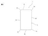
- FIG. 2 is a schematic plan view of the electricity storage device according to the embodiment of the present invention.
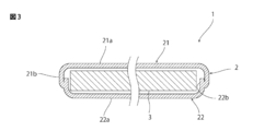
- 3 is a schematic cross-sectional view taken along line III-III in FIG. 4 is a schematic cross-sectional view taken along line IV-IV in FIG.
- FIG. 5 is a schematic perspective view when viewed from the direction of the arrow V in FIG. 1.
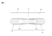
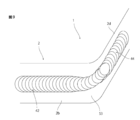
- FIG. 6 is a schematic plan view when viewed from the direction of arrow V in FIG.
- FIG. 7 is a schematic perspective view when viewed from the direction of the arrow VI in FIG.
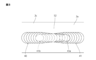
- FIG. 8 is a schematic plan view when viewed from the direction of the arrow VI in FIG.
- FIG. 1 is a schematic perspective view of an electricity storage device according to an embodiment of the present invention.
- FIG. 2 is a schematic plan view of the electricity storage device according to the embodiment of the present invention.
- 3 is a schematic cross-sectional view taken along line III
- FIG. 9 is a schematic perspective view when viewed from the direction of the arrow IX in FIG. 1.
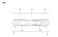
- FIG. 10 is a schematic plan view when viewed from the direction of the arrow IX in FIG.
- FIG. 11 is a schematic perspective view when viewed from the direction of the arrow XI in FIG.
- FIG. 12 is a schematic plan view when viewed from the direction of arrow XI in FIG.
- FIG. 1 is a schematic perspective view of the electricity storage device according to the present embodiment.
- FIG. 2 is a schematic plan view of the electricity storage device according to this embodiment.
- 3 is a schematic cross-sectional view taken along line III-III in FIG. 4 is a schematic cross-sectional view taken along line IV-IV in FIG.
- FIG. 5 is a schematic perspective view when viewed from the direction of the arrow V in FIG. 1.
- FIG. 6 is a schematic plan view when viewed from the direction of arrow V in FIG.
- FIG. 7 is a schematic perspective view when viewed from the direction of the arrow VI in FIG.
- FIG. 8 is a schematic plan view when viewed from the direction of the arrow VI in FIG.
- FIG. 9 is a schematic perspective view when viewed from the direction of the arrow IX in FIG. 1.
- FIG. 10 is a schematic plan view when viewed from the direction of the arrow IX in FIG.
- FIG. 11 is a schematic perspective view when viewed from the direction of the arrow XI in FIG.
- FIG. 12 is a schematic plan view when viewed from the direction of arrow XI in FIG.
- the electricity storage device 1 includes a case 2 and an electricity storage device body 3.
- the power storage device body 3 is not particularly limited as long as it can store electric power.
- the power storage device body 3 may be, for example, a battery such as a secondary battery, a capacitor such as an electric double layer capacitor, or the like.
- the electricity storage device body 3 may include an electrolytic solution.
- An electric storage device including an electrolytic solution may be decomposed due to the reaction of the electrolytic solution at a high temperature.
- an adverse effect on the electrolytic solution due to excess energy of the laser can be suppressed. It is suitable for an electricity storage device comprising
- the case 2 has a rectangular shape having a shape in which each of the four corners is rounded in a plan view. That is, the case 2 has a substantially rectangular parallelepiped shape having a shape with rounded corners.
- the shape of the case is not limited to a rectangular shape having a shape with rounded corners in plan view.
- the case is not particularly limited as long as it has a shape having a corner having a rounded shape.
- the case may have a rectangular shape in which a rectangular notch is provided at one corner and the other corners are rounded in plan view.
- the case 2 includes a first case piece 21 and a second case piece 22 that are welded to each other.
- the first case piece 21 and the second case piece 22 constitute the case 2.
- the first case piece 21 has a first bottom wall portion 21a and a first side wall portion 21b.
- the first bottom wall portion 21a has a rectangular shape in which each of the four corner portions is rounded.
- the first side wall portion 21b extends from the entire circumference of the first bottom wall portion 21a. Specifically, the first side wall portion 21b is perpendicular to the first bottom wall portion 21a from the entire circumference of the peripheral edge portion of the first bottom wall portion 21a toward the second case piece 22 side. Extending in the direction.
- the second case piece 22 has a second bottom wall portion 22a and a second side wall portion 22b.
- the second bottom wall portion 22a has a rectangular shape in which each of the four corner portions is rounded.
- the second side wall portion 22b extends from the entire circumference of the peripheral edge portion of the second bottom wall portion 22a. Specifically, the second side wall portion 22b extends from the entire circumference of the second bottom wall portion 22a toward the first case piece 21 in the direction perpendicular to the second bottom wall portion 22a. ing.
- first case piece 21 and the second case piece 22 at least a part of the first side wall part 21b and at least a part of the second side wall part 22b are arranged in the thickness direction of the side wall parts 21b and 22b. They are arranged to overlap.
- the 1st case piece 21 and the 2nd case piece 22 are joined by welding over the perimeter in the overlapping part of the 1st side wall part 21b and the 2nd side wall part 22b.
- the first case piece 21 and the second case piece 22 have a part of the first side wall part 21b and a part of the second side wall part 22b as side walls. It welds over the perimeter in the state located so that it may overlap in the thickness direction of the parts 21b and 22b.
- the material of the first case piece 21 and the second case piece 22 is not particularly limited.
- the 1st case piece 21 and the 2nd case piece 22 can each be comprised with metals, such as aluminum, aluminum alloy, stainless steel, for example.
- each of the first case piece 21 and the second case piece 22 is preferably small within a range in which the strength required for the case 2 can be secured from the viewpoint of downsizing the power storage device 1.
- the thickness of the first case piece 21 and the thickness of the second case piece 22 are each preferably 50 ⁇ m or more and 200 ⁇ m or less, and more preferably 80 ⁇ m or more and 150 ⁇ m or less.
- the first side wall portion 21b and the second side wall portion 22b are welded. For this reason, unlike the battery described in Patent Document 1, it is not necessary to provide a flange portion for welding protruding outward in the can body. For this reason, the electrical storage device 1 can be reduced in size.
- the first case piece 21, the second case piece 22, and the power storage device body 3 are prepared.
- the case 2 is manufactured by laser welding the overlapping portion of the first side wall portion 21b and the second side wall portion 22b over the entire circumference (welding step).
- the electrical storage device 1 can be completed by performing the above steps.
- a step of connecting a terminal such as a positive electrode terminal or a negative electrode terminal to the electricity storage device main body 3 or a step of forming an opening for drawing the terminal out of the case 2 may be further performed.
- laser beam may be intermittently irradiated, and spot-like weld marks may be continuously formed in a linear shape so that adjacent weld marks overlap, or laser light may be irradiated.
- a linear weld may be formed by displacing at least one of the laser light source and the first and second case pieces 21 and 22 and shifting the irradiation position of the laser light.
- laser welding is performed by laser welding at such a strength and time that the inner wall of the inner side wall of the first and second case pieces 21 and 22 does not protrude inward. It is preferable. Further, it is more preferable to perform laser welding at such a strength and time that the depth of the welding mark does not reach the inner wall of the side wall located inside.
- laser welding may be performed for each side surface.
- the welding on the first side surface of the first and second side wall portions 21b and 22b, the welding on the second side surface, the welding on the third side surface, and the welding on the fourth side surface may be performed individually and sequentially. . In that case, it is arbitrary from which side of the first to fourth sides the laser light is irradiated in order. Further, welding on the four side surfaces may be continuously performed while rotating the first and second case pieces 21 and 22.
- welding on the first side surface of the first and second side wall portions 21b and 22b, welding on the second side surface, welding on the third side surface, and welding on the fourth side surface are sequentially performed individually. An example will be described.
- first to fourth welds 41 to 44 are formed.
- the first welded portion 41 includes the first side surface 2a of the case 2, the first corner portions 51 (see FIGS. 5 and 6) located on both sides thereof, and the first side surface 2a. It is formed across two corners 52 (see FIGS. 7 and 8).
- the second welded portion 42 includes a second side surface 2 b of the case 2 and first corner portions 51 (see FIGS.
- the third welded portion 43 includes a third side surface 2c of the case 2, a second corner portion 52 (see FIGS. 7 and 8) and a fourth corner portion 54 (see FIGS. 12).
- the fourth welded portion 44 includes a fourth side surface 2d of the case 2, a third corner portion 53 (see FIGS. 9 and 10) and a fourth corner portion 54 (see FIGS. 11 and 10) located on both sides thereof. 12). Since the first to fourth welds 41 to 44 are formed as described above, as shown in FIG. 6, the first end 41a of the first weld 41 at the first corner 51, The first end portion 42a of the second welded portion 42 overlaps.
- the second corner portion 52 the second end portion 41 b of the first welded portion 41 and the first end portion 43 a of the third welded portion 43 overlap each other.
- angular part 54 the 2nd end part 43b of the 3rd welding part 43 and the 2nd end part 44b of the 4th welding part 44 have overlapped.
- the width of the welded portion formed on the corner portion of the case 2 among the welded portions formed on the side surface of the case 2 is narrower than the width of the welded portion formed on the side surface of the case 2.
- it is necessary to decrease the intensity of the laser beam to be irradiated increase the distance between the laser and the surface to be irradiated with the laser, or the like. That is, in order to narrow the width of the welded portion, it is necessary to reduce the intensity of the laser beam irradiated to that portion. Therefore, the corners 51 to 54 are not easily damaged. Accordingly, it is possible to realize the electricity storage device 1 having high corner strength and excellent durability.
- the electricity storage device body when the electricity storage device body is a lithium ion battery or an electric double layer capacitor, the electricity storage device body may contain an electrolytic solution.
- the case 2 In the electricity storage device 1 provided with such an electricity storage device body 3, the case 2 needs to be airtight. Therefore, it is necessary to reliably weld and join the first side wall portion 21b and the second side wall portion 22b over the entire circumference. Therefore, it is preferable that the first side wall part 21b and the second side wall part 22b are reliably welded over the entire circumference by overlapping the ends of the welded parts.
- the welded portions 41 to 44 are formed so that the tip portions overlap each other on the corner portions 51 to 54 of the case 2.
- laser welding is performed so that the tip portions of the welded portions 41 to 44 overlap each other on the respective corner portions 51 to 54 of the case 2.
- the welded portions 41 to 44 are formed so that the tip portions overlap each other on the corner portions 51 to 54 of the case 2.
- the corner portions 51 to 54 of the case 2 are irradiated with laser light having a low intensity to form a narrow welded portion. For this reason, when the corners 51 to 54 are irradiated with laser light a plurality of times so that the tips of the welds 41 to 44 overlap each other, the total damage applied to the corners 51 to 54 is small. Therefore, the case where the welded portion is overlapped by irradiating the corner portion with multiple times of laser light so that the width of the welded portion becomes narrower than the case where the welded portion is overlapped by irradiating the laser beam multiple times on the side surface. The damage applied to the case 2 can be reduced. Therefore, the electricity storage device 1 having excellent durability can be realized.
- the case pieces 21 and 22 are made of thin metal plates having a thickness of about 50 ⁇ m or more and 200 ⁇ m or less, the case pieces 21 and 22 are easily damaged by laser light irradiation. Therefore, it is effective to make the width of the welded portion formed on the corner portion narrower than the width of the welded portion formed on the side surface.
Landscapes
- Engineering & Computer Science (AREA)
- Physics & Mathematics (AREA)
- Optics & Photonics (AREA)
- Mechanical Engineering (AREA)
- Plasma & Fusion (AREA)
- Power Engineering (AREA)
- Chemical & Material Sciences (AREA)
- Chemical Kinetics & Catalysis (AREA)
- General Chemical & Material Sciences (AREA)
- Electrochemistry (AREA)
- Microelectronics & Electronic Packaging (AREA)
- Manufacturing & Machinery (AREA)
- Inorganic Chemistry (AREA)
- Sealing Battery Cases Or Jackets (AREA)
- Electric Double-Layer Capacitors Or The Like (AREA)
- Laser Beam Processing (AREA)
Abstract
小型な蓄電デバイスを提供する。 第1のケース片21と第2のケース片22とは、第1の側壁部21bと、第2の側壁部22bとが重ねられた部分において全周にわたって溶接されることにより接合されている。ケース2の側面2a、2b、2,c、2dに形成された溶接部41~44のうち、ケース2の角部51~54の上に形成された溶接部の幅が、ケース2の側面2a、2b、2,c、2dの上に形成された溶接部の幅よりも狭い。
Description
本発明は、蓄電デバイス及びその製造方法に関する。
従来、種々の電子機器の電源として、蓄電デバイスが用いられている。例えば、特許文献1には、周縁部にフランジ部が設けられた缶本体と、金属蓋とがフランジ部において溶接されることにより構成された電池缶に電極体が収容された電池が記載されている。
近年、電子機器の小型化が進んできており、それに伴い、蓄電デバイスの小型化への要求が高まってきている。
本発明の主な目的は、小型な蓄電デバイスを提供することにある。
本発明に係る蓄電デバイスは、ケースと、蓄電デバイス本体とを備える。ケースは、平面視において丸められた形状の角部を有する。蓄電デバイス本体は、ケース内に配されている。ケースは、第1のケース片と、第2のケース片とを有する。第2のケース片は、第1のケース片と共にケースを構成している。第1のケース片は、第1の底壁部と、第1の側壁部とを含む。第1の側壁部は、第1の底壁部の全周から延びている。第2のケース片は、第2の底壁部と、第2の側壁部とを含む。第2の側壁部は、第2の底壁部の全周から延びている。第2の側壁部は、第1の側壁部と重なっている。第1のケース片と第2のケース片とは、第1の側壁部と、第2の側壁部とが重ねられた部分において全周にわたって溶接されている。ケースの側面に形成された溶接部のうち、ケースの角部の上に形成された溶接部の幅が、ケースの側面の上に形成された溶接部の幅よりも狭い。
本発明に係る蓄電デバイスは、第1の側壁部と第2の側壁部とが溶接されている。このため、特許文献1に記載の電池のように、缶本体にフランジ部を設ける必要がない。従って、本発明に係る蓄電デバイスは、小型である。
本発明に係る蓄電デバイスでは、溶接部は、ケースの角部の上において先端部同士が重なるように形成されていることが好ましい。
本発明に係る蓄電デバイスでは、溶接部が、ケースの第1の側面の上に設けられた第1の溶接部と、ケースの第2の側面の上に設けられた第2の溶接部と、ケースの第3の側面の上に設けられた第3の溶接部と、ケースの第4の側面の上に設けられた第4の溶接部とを含み、ケースの第1の側面と第2の側面とを接続している第1の角部において第1の溶接部の一方側端部と、第2の溶接部の一方側端部が重なっており、ケースの第1の側面と第3の側面とを接続している第2の角部において第1の溶接部の他方側端部と、第3の溶接部の一方側端部とが重なっており、ケースの第2の側面と第4の側面とを接続している第3の角部において、第2の溶接部の他方側端部と、第4の溶接部の一方側端部とが重なっており、ケースの第3の側面と第4の側面とを接続している第4の角部において、第3の溶接部の他方側端部と、第4の溶接部の他方側端部とが重なっていてもよい。
本発明に係る蓄電デバイスでは、第1及び第2のケース片は、それぞれ、厚みが50μm以上200μm以下である金属板により構成されていることが好ましい。
本発明に係る蓄電デバイスでは、蓄電デバイス本体が電解液を含んでいてもよい。
本発明に係る蓄電デバイスの製造方法は、平面視において丸められた形状を有する角部を有するのケースと、ケース内に配された蓄電デバイス本体とを備える蓄電デバイスの製造方法に関する。本発明に係る蓄電デバイスの製造方法は、第1の底壁部と、第1の底壁部の全周から延びる第1の側壁部とを含む第1のケース片と、第2の底壁部と、第2の底壁部の全周から延びる第2の側壁部とを含む第2のケース片とを、第1の側壁部と第2の側壁部とが重なるように配置した状態で、第1の側壁部と第2の側壁部との重なり部分を全周にわたってレーザー溶接することによりケースを作製する溶接工程を備える。溶接工程において、ケースの側面に形成された溶接部のうち、ケースの角部の上に形成された溶接部の幅が、ケースの側面の上に形成された溶接部の幅よりも狭くなるようにレーザー溶接を行う。
本発明に係る蓄電デバイスの製造方法では、溶接工程において、ケースの側面に形成された溶接部のうち、ケースの角部の上に形成された溶接部の幅が、ケースの側面の上に形成された溶接部の幅よりも狭くなるようにレーザー溶接を行う。レーザー溶接の場合、レーザービームのビーム径とエネルギー、照射時間によって、溶接痕の大きさ(表面側の面積および深さ)が決定される。溶接部はこの溶接痕が連続して帯状に形成されており、溶接部の幅が狭くなっているということは、その部分の個々の溶接痕の大きさが小さくなっていることを示している。このため、レーザー溶接時に熱がこもりやすく、損傷しやすいケースの角部のレーザー溶接による損傷を抑制することができる。従って、ケースに溶接するためのフランジ部を設けなくても第1のケース片と第2のケース片とを好適に溶接でき、ケースを作製することができる。従って、本発明に係る蓄電デバイスの製造方法によれば、小型な蓄電デバイスを好適に製造することができる。
本発明に係る蓄電デバイスの製造方法では、溶接工程において、ケースの角部の上において溶接部の先端部同士が重なるようにレーザー溶接を行うことが好ましい。
本発明に係る蓄電デバイスの製造方法では、溶接工程において、ケースの各角部の上において溶接部の先端部同士が重なるようにレーザー溶接を行ってもよい。
本発明によれば、小型な蓄電デバイスを提供することができる。
以下、本発明を実施した好ましい形態の一例について説明する。但し、下記の実施形態は、単なる例示である。本発明は、下記の実施形態に何ら限定されない。
また、実施形態等において参照する各図面において、実質的に同一の機能を有する部材は同一の符号で参照することとする。また、実施形態等において参照する図面は、模式的に記載されたものである。図面に描画された物体の寸法の比率などは、現実の物体の寸法の比率などとは異なる場合がある。図面相互間においても、物体の寸法比率等が異なる場合がある。具体的な物体の寸法比率等は、以下の説明を参酌して判断されるべきである。
図1は、本実施形態に係る蓄電デバイスの模式的斜視図である。図2は、本実施形態に係る蓄電デバイスの模式的平面図である。図3は、図1の線III-IIIにおける模式的断面図である。図4は、図1の線IV-IVにおける模式的断面図である。図5は、図1の矢印Vの方向から視た際の模式的斜視図である。図6は、図1の矢印Vの方向から視た際の模式的平面図である。図7は、図1の矢印VIの方向から視た際の模式的斜視図である。図8は、図1の矢印VIの方向から視た際の模式的平面図である。図9は、図1の矢印IXの方向から視た際の模式的斜視図である。図10は、図1の矢印IXの方向から視た際の模式的平面図である。図11は、図1の矢印XIの方向から視た際の模式的斜視図である。図12は、図1の矢印XIの方向から視た際の模式的平面図である。
図3及び図4に示すように、蓄電デバイス1は、ケース2と、蓄電デバイス本体3とを備えている。
蓄電デバイス本体3は、電力を蓄えることができるものであれば特に限定されない。蓄電デバイス本体3は、例えば、二次電池等の電池、電気二重層コンデンサ等のコンデンサ等であってもよい。蓄電デバイス本体3は、電解液を備えるものであってもよい。電解液を備える蓄電デバイスは、高温で電解液が反応して分解する恐れがあるが、本発明によれば、レーザーの余剰エネルギーによる電解液への悪影響を抑制できるので、本発明は、電解液を備える蓄電デバイスに好適である。
図2に示すように、本実施形態では、ケース2は、平面視において4つの角部のそれぞれが丸められた形状を有する矩形状である。すなわち、ケース2は、各角部が丸められた形状を有する略直方体状である。但し、本発明において、ケースの形状は、平面視において角部が丸められた形状を有する矩形状に限定されない。ケースは、丸められた形状を有する角部を有する形状のものである限りにおいて特に限定されない。ケースは、例えば、平面視において、一つの角部に矩形状の切欠部が設けられており、それ以外の角部が丸められた形状を有する矩形状であってもよい。
図3及び図4に示すように、ケース2は、互いに溶接されている第1のケース片21と、第2のケース片22とにより構成されている。これら第1のケース片21と第2のケース片22とによりケース2が構成されている。
第1のケース片21は、第1の底壁部21aと、第1の側壁部21bとを有する。第1の底壁部21aは、4つの角部のそれぞれが丸められた矩形状である。第1の側壁部21bは、第1の底壁部21aの全周から延びている。具体的には、第1の側壁部21bは、第1の底壁部21aの周縁部の全周から、第2のケース片22側に向かって第1の底壁部21aに対して垂直な方向に延びている。
第2のケース片22は、第2の底壁部22aと、第2の側壁部22bとを有する。第2の底壁部22aは、4つの角部のそれぞれが丸められた矩形状である。第2の側壁部22bは、第2の底壁部22aの周縁部の全周から延びている。具体的には、第2の側壁部22bは、第2の底壁部22aの全周から、第1のケース片21側に向かって第2の底壁部22aに対して垂直な方向に延びている。
第1のケース片21と、第2のケース片22とは、第1の側壁部21bの少なくとも一部と、第2の側壁部22bの少なくとも一部とが側壁部21b、22bの厚み方向に重なるように配されている。第1のケース片21と第2のケース片22とは、第1の側壁部21bと第2の側壁部22bとの重畳部において全周にわたって溶接されることにより接合されている。本実施形態では、具体的には、第1のケース片21と、第2のケース片22とが、第1の側壁部21bの一部と、第2の側壁部22bの一部とが側壁部21b、22bの厚み方向に重なるように位置した状態で全周にわたって溶接されている。
第1のケース片21と、第2のケース片22との材質は、特に限定されない。第1のケース片21と、第2のケース片22とは、それぞれ、例えば、アルミニウム、アルミニウム合金、ステンレス等の金属によって構成することができる。
第1のケース片21と第2のケース片22とのそれぞれの厚みは、蓄電デバイス1を小型化する観点から、ケース2に要求される強度を担保できる範囲内において小さいことが好ましい。具体的には、第1のケース片21の厚みと第2のケース片22の厚みとは、それぞれ、50μm以上200μm以下であることが好ましく、80μm以上150μm以下であることがより好ましい。
以上のように、蓄電デバイス1では、第1の側壁部21bと第2の側壁部22bとが溶接されている。このため、特許文献1に記載の電池のように、缶本体に外方に向かって突出する溶接用のフランジ部を設ける必要がない。このため、蓄電デバイス1を小型化することができる。
次に、蓄電デバイス1の製造方法の一例について説明する。
まず、第1のケース片21と、第2のケース片22と、蓄電デバイス本体3とを用意する。
次に、蓄電デバイス本体3を第1のケース片21と第2のケース片22との間に介在させた状態で、第1のケース片21の第1の側壁部21bの少なくとも一部分と、第2のケース片22の第2の側壁部22bの少なくとも一部分とが重なるように、第1及び第2のケース片21,22並びに蓄電デバイス本体3を配置する。その状態で、第1の側壁部21bと第2の側壁部22bとの重なり部分を全周にわたってレーザー溶接することにより、ケース2を作製する(溶接工程)。以上の工程を行うことにより、蓄電デバイス1を完成させることができる。
尚、例えば、正極端子や負極端子等の端子を蓄電デバイス本体3に接続する工程や、端子をケース2外に引き出すための開口をケース2に形成する工程をさらに行ってもよい。
溶接工程において、レーザー光を間欠的に照射し、スポット状の溶接痕を、隣接する溶接痕が重なるように連続して線状に溶接部を形成していってもよいし、レーザー光を照射したまま、レーザー光源及び第1及び第2のケース片21,22の少なくとも一方を変位させていき、レーザー光の照射位置をずらしていくことにより、線状の溶接部を形成してもよい。
溶接工程においては、レーザー溶接により、第1及び第2のケース片21,22の側壁21b、22bのうち、内側に位置する側壁の内壁が内側に突出しない程度の強度及び時間でレーザー溶接を行うことが好ましい。また、溶接痕の深さが内側に位置する側壁の内壁に到達しない程度の強度及び時間でレーザー溶接を行うことがさらに好ましい。
溶接工程において、各側面毎にレーザー溶接を行ってもよい。例えば、第1及び第2の側壁部21b、22bの第1の側面における溶接、第2の側面における溶接、第3の側面における溶接、第4の側面における溶接を、個別に順次行ってもよい。その場合において、第1~第4の側面のどの側面から順番にレーザー光の照射を行っていくかは任意である。また、第1及び第2のケース片21,22を回転させながら4つの側面における溶接を連続して行ってもよい。
本実施形態では、第1及び第2の側壁部21b、22bの第1の側面における溶接、第2の側面における溶接、第3の側面における溶接、第4の側面における溶接を、個別に順次行う例について説明する。
第1及び第2の側壁部21b、22bの第1の側面における溶接、第2の側面における溶接、第3の側面における溶接、第4の側面における溶接を、個別に順次行った場合、個々の溶接痕が連続する4本の線状の溶接部が形成される。具体的には、第1~第4の溶接部41~44が形成される。図5~図8に示すように、第1の溶接部41は、ケース2の第1の側面2aと、その両側に位置する第1の角部51(図5及び図6を参照)及び第2の角部52(図7及び図8を参照)とに跨がって形成される。図5,図6,図9及び図10に示すように、第2の溶接部42は、ケース2の第2の側面2bと、その両側に位置する第1の角部51(図5及び図6を参照)及び第3の角部53(図9及び図10を参照)とに跨がって形成される。第3の溶接部43は、ケース2の第3の側面2cと、その両側に位置する第2の角部52(図7及び図8を参照)及び第4の角部54(図11及び図12を参照)とに跨がって形成される。第4の溶接部44は、ケース2の第4の側面2dと、その両側に位置する第3の角部53(図9及び図10を参照)及び第4の角部54(図11及び図12を参照)とに跨がって形成される。以上のように第1~4の溶接部41~44が形成されているため、図6に示すように、第1の角部51において第1の溶接部41の第1の端部41aと、第2の溶接部42の第1の端部42aとが重なっている。第2の角部52において第1の溶接部41の第2の端部41bと第3の溶接部43の第1の端部43aとが重なっている。第3の角部53において第2の溶接部42の第2の端部42bと第4の溶接部44の第1の端部44aとが重なっている。第4の角部54において第3の溶接部43の第2の端部43bと、第4の溶接部44の第2の端部44bとが重なっている。
ところで、ケース2の角部51~54にレーザー光を照射した場合、ケース2の側面2a、2b、2c、2dにレーザー光を照射した場合よりも、熱がこもりやすい。このため、レーザー溶接をケース2の全周にわたって行う場合は、角部へのダメージが大きくなりやすい。そこで、本実施形態では、溶接工程において、ケース2の側面に形成された溶接部のうち、ケース2の角部の上に形成された溶接部の幅(ケース2の厚み方向に沿った幅)が、ケース2の側面に形成された溶接部の幅(ケース2の厚み方向に沿った幅)よりも狭くなるようにレーザー光を照射し、レーザー溶接を行う。このため、ケース2の側面に形成された溶接部のうち、ケース2の角部の上に形成された溶接部の幅が、ケース2の側面の上に形成された溶接部の幅よりも狭くなる。溶接部の幅を狭くするためには、照射するレーザー光の強度を低くする、レーザーと、レーザーの被照射面との間の距離を長くする等の必要がある。すなわち、溶接部の幅を狭くするためには、その部分に照射されるレーザー光の強度を低くする必要がある。このため、角部51~54が損傷しにくい。従って、角部の強度が高く、耐久性に優れた蓄電デバイス1を実現することができる。
ところで、例えば、蓄電デバイス本体がリチウムイオン電池や電気二重層コンデンサであるときのように、蓄電デバイス本体が電解液を含む場合もある。そのような蓄電デバイス本体3を備える蓄電デバイス1などにおいては、ケース2を気密にする必要がある。このため、第1の側壁部21bと第2の側壁部22bとを全周にわたって確実に溶接して接合する必要がある。従って、溶接部の端部同士を重ね合わせるようにして、第1の側壁部21bと第2の側壁部22bとが全周にわたって確実に溶接されるようにすることが好ましい。
しかしながら、溶接部の端部同士を重ね合わせるためには、その部分に複数回にわたってレーザー光を照射する必要がある。従って、ケースのうち、そのレーザー光が複数回にわたって照射された部分が脆弱になる虞がある。ここで、ケースの側面に照射されるレーザー光の強度は高いため、ケースの側面に複数回にわたってレーザー光を照射し、溶接部の端部同士を重ね合わせた場合は、その部分に大きな熱量が加わり、脆弱になるため、ケースが損傷する虞がある。
それに対して、本実施形態では、溶接工程において、ケース2の角部51~54の上において溶接部の先端部同士が重なるようにレーザー溶接を行う。このため、蓄電デバイス1において、ケース2の角部51~54の上において先端部同士が重なるように溶接部41~44が形成される。具体的には、溶接工程において、ケース2の各角部51~54の上において溶接部41~44の先端部同士が重なるようにレーザー溶接を行う。このため、蓄電デバイス1において、ケース2の各角部51~54の上において先端部同士が重なるように溶接部41~44が形成される。
上述のように、ケース2の角部51~54には、強度の低いレーザー光が照射され、幅狭の溶接部が形成される。このため、角部51~54に複数回レーザー光を照射し、溶接部41~44の先端部同士が重なるようにした場合は、角部51~54に加わる総ダメージが小さい。従って、側面に複数回レーザー光を照射して溶接部を重ねた場合よりも、溶接部の幅が狭くなるように角部に複数回レーザー光を照射して溶接部を重ねた場合の方が、ケース2に加わるダメージを小さくすることができる。従って、耐久性に優れた蓄電デバイス1を実現することができる。
特に、例えば、厚みが50μm以上200μm以下程度の薄い金属板により第1及び第2のケース片21,22が構成されている場合は、レーザー光の照射によりケース片21,22が損傷しやすい。従って、角部の上に形成された溶接部の幅を、側面の上に形成された溶接部の幅よりも狭くすることが効果的である。
1 蓄電デバイス
2 ケース
2a 第1の側面
2b 第2の側面
2c 第3の側面
2d 第4の側面
3 蓄電デバイス本体
21 第1のケース片
22 第2のケース片
21a 第1の底壁部
21b 第1の側壁部
22a 第2の底壁部
22b 第2の側壁部
41 第1の溶接部
41a 第1の溶接部の第1の端部
41b 第1の溶接部の第2の端部
42 第2の溶接部
42a 第2の溶接部の第1の端部
42b 第2の溶接部の第2の端部
43 第3の溶接部
43a 第3の溶接部の第1の端部
43b 第3の溶接部の第2の端部
44 第4の溶接部
44a 第4の溶接部の第1の端部
44b 第4の溶接部の第2の端部
51 第1の角部
52 第2の角部
53 第3の角部
54 第4の角部
2 ケース
2a 第1の側面
2b 第2の側面
2c 第3の側面
2d 第4の側面
3 蓄電デバイス本体
21 第1のケース片
22 第2のケース片
21a 第1の底壁部
21b 第1の側壁部
22a 第2の底壁部
22b 第2の側壁部
41 第1の溶接部
41a 第1の溶接部の第1の端部
41b 第1の溶接部の第2の端部
42 第2の溶接部
42a 第2の溶接部の第1の端部
42b 第2の溶接部の第2の端部
43 第3の溶接部
43a 第3の溶接部の第1の端部
43b 第3の溶接部の第2の端部
44 第4の溶接部
44a 第4の溶接部の第1の端部
44b 第4の溶接部の第2の端部
51 第1の角部
52 第2の角部
53 第3の角部
54 第4の角部
Claims (8)
- 平面視において丸められた形状を有する角部を有するケースと、
前記ケース内に配された蓄電デバイス本体と、
を備える蓄電デバイスであって、
前記ケースは、
第1のケース片と、
前記第1のケース片と共に前記ケースを構成している第2のケース片と、
を有し、
前記第1のケース片は、
第1の底壁部と、
前記第1の底壁部の全周から延びる第1の側壁部と、
を含み、
前記第2のケース片は、
第2の底壁部と、
前記第2の底壁部の全周から延びており、前記第1の側壁部と重なっている第2の側壁部と、
を含み、
前記第1のケース片と前記第2のケース片とは、前記第1の側壁部と、前記第2の側壁部とが重ねられた部分において全周にわたって溶接されており、
前記ケースの側面に形成された溶接部のうち、前記ケースの角部の上に形成された溶接部の幅が、前記ケースの側面の上に形成された溶接部の幅よりも狭い、蓄電デバイス。 - 前記溶接部は、前記ケースの角部の上において先端部同士が重なるように形成されている、請求項1に記載の蓄電デバイス。
- 前記溶接部は、
前記ケースの第1の側面の上に設けられた第1の溶接部と、
前記ケースの第2の側面の上に設けられた第2の溶接部と、
前記ケースの第3の側面の上に設けられた第3の溶接部と、
前記ケースの第4の側面の上に設けられた第4の溶接部と、
を含み、
前記ケースの第1の側面と第2の側面とを接続している第1の角部において前記第1の溶接部の一方側端部と、前記第2の溶接部の一方側端部が重なっており、
前記ケースの第1の側面と第3の側面とを接続している第2の角部において前記第1の溶接部の他方側端部と、前記第3の溶接部の一方側端部とが重なっており、
前記ケースの第2の側面と第4の側面とを接続している第3の角部において、前記第2の溶接部の他方側端部と、前記第4の溶接部の一方側端部とが重なっており、
前記ケースの第3の側面と第4の側面とを接続している第4の角部において、前記第3の溶接部の他方側端部と、前記第4の溶接部の他方側端部とが重なっている、請求項2に記載の蓄電デバイス。 - 前記第1及び第2のケース片は、それぞれ、厚みが50μm以上200μm以下である金属板により構成されている、請求項1~3のいずれか一項に記載の蓄電デバイス。
- 前記蓄電デバイス本体が電解液を含む、請求項1~4のいずれか一項に記載の蓄電デバイス。
- 平面視において丸められた形状を有する角部を有するケースと、前記ケース内に配された蓄電デバイス本体とを備える蓄電デバイスの製造方法であって、
第1の底壁部と、前記第1の底壁部の全周から延びる第1の側壁部とを含む第1のケース片と、第2の底壁部と、前記第2の底壁部の全周から延びる第2の側壁部とを含む第2のケース片とを、前記第1の側壁部と前記第2の側壁部とが重なるように配置した状態で、前記第1の側壁部と前記第2の側壁部との重なり部分を全周にわたってレーザー溶接することにより前記ケースを作製する溶接工程を備え、
前記溶接工程において、前記ケースの側面に形成された溶接部のうち、前記ケースの角部の上に形成された溶接部の幅が、前記ケースの側面の上に形成された溶接部の幅よりも狭くなるように前記レーザー溶接を行う、蓄電デバイスの製造方法。 - 前記溶接工程において、前記ケースの角部の上において前記溶接部の先端部同士が重なるように前記レーザー溶接を行う、請求項6に記載の蓄電デバイスの製造方法。
- 前記溶接工程において、前記ケースの各角部の上において前記溶接部の先端部同士が重なるように前記レーザー溶接を行う、請求項7に記載の蓄電デバイスの製造方法。
Priority Applications (3)
| Application Number | Priority Date | Filing Date | Title |
|---|---|---|---|
| JP2017561593A JPWO2017122572A1 (ja) | 2016-01-16 | 2017-01-05 | 蓄電デバイス及びその製造方法 |
| CN201780005372.5A CN108475739A (zh) | 2016-01-16 | 2017-01-05 | 蓄电设备及其制造方法 |
| US16/007,031 US20180294446A1 (en) | 2016-01-16 | 2018-06-13 | Electric storage device and method for manufacturing the same |
Applications Claiming Priority (4)
| Application Number | Priority Date | Filing Date | Title |
|---|---|---|---|
| JP2016-006707 | 2016-01-16 | ||
| JP2016006707 | 2016-01-16 | ||
| JP2016-007454 | 2016-01-18 | ||
| JP2016007454 | 2016-01-18 |
Related Child Applications (1)
| Application Number | Title | Priority Date | Filing Date |
|---|---|---|---|
| US16/007,031 Continuation US20180294446A1 (en) | 2016-01-16 | 2018-06-13 | Electric storage device and method for manufacturing the same |
Publications (1)
| Publication Number | Publication Date |
|---|---|
| WO2017122572A1 true WO2017122572A1 (ja) | 2017-07-20 |
Family
ID=59311250
Family Applications (1)
| Application Number | Title | Priority Date | Filing Date |
|---|---|---|---|
| PCT/JP2017/000150 Ceased WO2017122572A1 (ja) | 2016-01-16 | 2017-01-05 | 蓄電デバイス及びその製造方法 |
Country Status (4)
| Country | Link |
|---|---|
| US (1) | US20180294446A1 (ja) |
| JP (1) | JPWO2017122572A1 (ja) |
| CN (1) | CN108475739A (ja) |
| WO (1) | WO2017122572A1 (ja) |
Cited By (1)
| Publication number | Priority date | Publication date | Assignee | Title |
|---|---|---|---|---|
| JP2024125706A (ja) * | 2023-03-06 | 2024-09-19 | プライムプラネットエナジー&ソリューションズ株式会社 | 蓄電デバイス及び蓄電デバイスの製造方法 |
Families Citing this family (3)
| Publication number | Priority date | Publication date | Assignee | Title |
|---|---|---|---|---|
| US11830672B2 (en) | 2016-11-23 | 2023-11-28 | KYOCERA AVX Components Corporation | Ultracapacitor for use in a solder reflow process |
| WO2024159398A1 (zh) * | 2023-01-31 | 2024-08-08 | 宁德时代新能源科技股份有限公司 | 电池单体、电池及用电装置 |
| JP7737418B2 (ja) * | 2023-03-06 | 2025-09-10 | プライムプラネットエナジー&ソリューションズ株式会社 | 蓄電デバイス及び蓄電デバイスの製造方法 |
Citations (2)
| Publication number | Priority date | Publication date | Assignee | Title |
|---|---|---|---|---|
| JPH08315789A (ja) * | 1995-03-14 | 1996-11-29 | Nippondenso Co Ltd | 角形電池の製造方法 |
| JP2012038603A (ja) * | 2010-08-09 | 2012-02-23 | Nisshin Steel Co Ltd | 金属製の有底又は密閉容器およびその製造方法 |
-
2017
- 2017-01-05 WO PCT/JP2017/000150 patent/WO2017122572A1/ja not_active Ceased
- 2017-01-05 CN CN201780005372.5A patent/CN108475739A/zh not_active Withdrawn
- 2017-01-05 JP JP2017561593A patent/JPWO2017122572A1/ja active Pending
-
2018
- 2018-06-13 US US16/007,031 patent/US20180294446A1/en not_active Abandoned
Patent Citations (2)
| Publication number | Priority date | Publication date | Assignee | Title |
|---|---|---|---|---|
| JPH08315789A (ja) * | 1995-03-14 | 1996-11-29 | Nippondenso Co Ltd | 角形電池の製造方法 |
| JP2012038603A (ja) * | 2010-08-09 | 2012-02-23 | Nisshin Steel Co Ltd | 金属製の有底又は密閉容器およびその製造方法 |
Cited By (2)
| Publication number | Priority date | Publication date | Assignee | Title |
|---|---|---|---|---|
| JP2024125706A (ja) * | 2023-03-06 | 2024-09-19 | プライムプラネットエナジー&ソリューションズ株式会社 | 蓄電デバイス及び蓄電デバイスの製造方法 |
| JP7688668B2 (ja) | 2023-03-06 | 2025-06-04 | プライムプラネットエナジー&ソリューションズ株式会社 | 蓄電デバイス及び蓄電デバイスの製造方法 |
Also Published As
| Publication number | Publication date |
|---|---|
| US20180294446A1 (en) | 2018-10-11 |
| JPWO2017122572A1 (ja) | 2018-08-16 |
| CN108475739A (zh) | 2018-08-31 |
Similar Documents
| Publication | Publication Date | Title |
|---|---|---|
| JP6183555B2 (ja) | 組電池のタブ溶接方法 | |
| JP5821605B2 (ja) | 二次電池 | |
| JP6536885B2 (ja) | 電池容器の製造方法および電池容器 | |
| US20150183058A1 (en) | Welding device, welding method, and method for producing battery (as amended) | |
| JP2015099681A (ja) | 密閉型電池 | |
| CN109475979B (zh) | 能量存储装置和制造这种能量存储装置的方法 | |
| WO2017122572A1 (ja) | 蓄電デバイス及びその製造方法 | |
| JP4929606B2 (ja) | 密閉型蓄電装置及びその製造方法 | |
| CN103620824A (zh) | 蓄电器件以及蓄电器件的制造方法 | |
| JP5884692B2 (ja) | レーザ溶接方法 | |
| WO2012165567A1 (ja) | 電池用負極端子および電池用負極端子の製造方法 | |
| JP2016025013A (ja) | 組電池 | |
| JP2010097770A (ja) | 電池筐体、二次電池及び二次電池の製造方法 | |
| JP6286354B2 (ja) | 蓄電装置及び溶接方法 | |
| JP2016038995A (ja) | 蓄電装置および蓄電装置の製造方法 | |
| JP6031958B2 (ja) | 密閉容器及び密閉容器の製造方法 | |
| JP6115400B2 (ja) | 蓄電装置及び蓄電装置の製造方法 | |
| CN102689094B (zh) | 对具有单个共同焊接截面的多板件工件堆叠结构的能束焊接 | |
| JP2015115223A (ja) | 密閉型電池の製造方法 | |
| JP6586868B2 (ja) | 電極組立体の製造方法 | |
| JP6922328B2 (ja) | 電極組立体の製造方法 | |
| JP6683066B2 (ja) | 電極溶接方法 | |
| JP5966904B2 (ja) | 蓄電装置 | |
| JP2015159073A (ja) | 蓄電装置 | |
| JP5692154B2 (ja) | 非水電解質二次電池 |
Legal Events
| Date | Code | Title | Description |
|---|---|---|---|
| 121 | Ep: the epo has been informed by wipo that ep was designated in this application |
Ref document number: 17738327 Country of ref document: EP Kind code of ref document: A1 |
|
| ENP | Entry into the national phase |
Ref document number: 2017561593 Country of ref document: JP Kind code of ref document: A |
|
| NENP | Non-entry into the national phase |
Ref country code: DE |
|
| 122 | Ep: pct application non-entry in european phase |
Ref document number: 17738327 Country of ref document: EP Kind code of ref document: A1 |