WO2017122453A1 - 車両用空調装置 - Google Patents
車両用空調装置 Download PDFInfo
- Publication number
- WO2017122453A1 WO2017122453A1 PCT/JP2016/085786 JP2016085786W WO2017122453A1 WO 2017122453 A1 WO2017122453 A1 WO 2017122453A1 JP 2016085786 W JP2016085786 W JP 2016085786W WO 2017122453 A1 WO2017122453 A1 WO 2017122453A1
- Authority
- WO
- WIPO (PCT)
- Prior art keywords
- peristaltic
- vehicle
- sensor
- air conditioner
- air
- Prior art date
- Legal status (The legal status is an assumption and is not a legal conclusion. Google has not performed a legal analysis and makes no representation as to the accuracy of the status listed.)
- Ceased
Links
Images

Classifications
-
- B—PERFORMING OPERATIONS; TRANSPORTING
- B60—VEHICLES IN GENERAL
- B60H—ARRANGEMENTS OF HEATING, COOLING, VENTILATING OR OTHER AIR-TREATING DEVICES SPECIALLY ADAPTED FOR PASSENGER OR GOODS SPACES OF VEHICLES
- B60H1/00—Heating, cooling or ventilating devices
- B60H1/00642—Control systems or circuits; Control members or indication devices for heating, cooling or ventilating devices
- B60H1/00735—Control systems or circuits characterised by their input, i.e. by the detection, measurement or calculation of particular conditions, e.g. signal treatment, dynamic models
- B60H1/00742—Control systems or circuits characterised by their input, i.e. by the detection, measurement or calculation of particular conditions, e.g. signal treatment, dynamic models by detection of the vehicle occupants' presence; by detection of conditions relating to the body of occupants, e.g. using radiant heat detectors
-
- B—PERFORMING OPERATIONS; TRANSPORTING
- B60—VEHICLES IN GENERAL
- B60H—ARRANGEMENTS OF HEATING, COOLING, VENTILATING OR OTHER AIR-TREATING DEVICES SPECIALLY ADAPTED FOR PASSENGER OR GOODS SPACES OF VEHICLES
- B60H1/00—Heating, cooling or ventilating devices
- B60H1/00457—Ventilation unit, e.g. combined with a radiator
- B60H1/00471—The ventilator being of the radial type, i.e. with radial expulsion of the air
-
- B—PERFORMING OPERATIONS; TRANSPORTING
- B60—VEHICLES IN GENERAL
- B60H—ARRANGEMENTS OF HEATING, COOLING, VENTILATING OR OTHER AIR-TREATING DEVICES SPECIALLY ADAPTED FOR PASSENGER OR GOODS SPACES OF VEHICLES
- B60H1/00—Heating, cooling or ventilating devices
- B60H1/00642—Control systems or circuits; Control members or indication devices for heating, cooling or ventilating devices
- B60H1/00735—Control systems or circuits characterised by their input, i.e. by the detection, measurement or calculation of particular conditions, e.g. signal treatment, dynamic models
- B60H1/00792—Arrangement of detectors
-
- G—PHYSICS
- G01—MEASURING; TESTING
- G01V—GEOPHYSICS; GRAVITATIONAL MEASUREMENTS; DETECTING MASSES OR OBJECTS; TAGS
- G01V8/00—Prospecting or detecting by optical means
- G01V8/10—Detecting, e.g. by using light barriers
- G01V8/12—Detecting, e.g. by using light barriers using one transmitter and one receiver
Definitions
- the present disclosure relates to a vehicle air conditioner provided in a vehicle.
- a vehicle air conditioner that measures the surface temperature of an occupant with an infrared sensor and performs air conditioning control based on the surface temperature is known.
- an infrared sensor is disposed on a swing louver provided at the air outlet, and the surface temperature of the occupant is calculated by the infrared sensor.
- the direction of the infrared sensor periodically changes within a certain range with the swing of the swing louver.
- the entire temperature distribution is detected by gradually moving the range while measuring the local range. Yes. For this reason, it is possible to measure a wide range of temperatures including passengers while using an inexpensive infrared sensor with a relatively narrow detection range.
- the infrared sensor is arranged at a position where radiation (infrared rays) from each occupant including the driver can reach directly. For this reason, as described in Patent Document 1, an infrared sensor is often disposed at a position on the front side of the driver and relatively close to the driver. When the infrared sensor is oscillated at such a position, the driver may feel bothered by the infrared sensor and the operation sound associated therewith.
- the present disclosure has been made in view of such a problem, and a purpose of the present disclosure is to make it possible to prevent the driver from feeling troublesome for the driver even though the temperature detector is configured to swing. It is to provide an air-conditioning apparatus.
- the vehicle air conditioner includes a temperature detection unit (310) that detects a surface temperature of an object based on radiation from the object, and a detected area that is a region in which the surface temperature is detected by the temperature detection unit.
- a peristaltic mechanism unit (320) that perturbs the temperature detection unit so as to change the position of the region, and a control unit (100) that controls the operation of the peristaltic mechanism unit are provided.
- the control unit changes the operation of the peristaltic mechanism unit based on the magnitude of the thermal load in the passenger compartment.
- the temperature in the passenger compartment is too high or too low. For this reason, for example, fine air conditioning that intensively cools only the high temperature portion is not performed, and the air conditioning is performed with the maximum performance. That is, when the thermal load is large, it is less necessary to acquire the entire temperature distribution in the vehicle interior by the infrared sensor. Therefore, if the temperature detection unit is not constantly oscillated, but only limited when the thermal load in the passenger compartment is small, for example, the burden on the driver can be reduced without impairing the comfort of the air conditioning. It can be suppressed as much as possible.
- the operation of the peristaltic mechanism unit that is, the perturbation of the temperature detection unit is changed based on the magnitude of the thermal load in the passenger compartment.
- a vehicle air conditioner that can suppress the perception of the perturbation by the driver while the configuration is such that the temperature detection unit is perturbed.
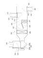
- FIG. 1 is a diagram schematically illustrating a configuration of a vehicle air conditioner according to the first embodiment and a configuration of a vehicle on which the vehicle air conditioner is mounted.
- FIG. 2 is a diagram illustrating a configuration of the air-conditioning mechanism unit.
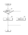
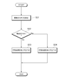
- FIG. 3 is a flowchart showing a flow of processing executed by the control unit.
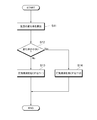
- FIG. 4 is a flowchart showing a flow of processing executed by the control unit.
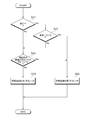
- FIG. 5 is a flowchart showing a flow of processing executed by the control unit.
- FIG. 6 is a flowchart showing the flow of processing executed by the control unit.
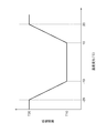
- FIG. 7 is a diagram for explaining the setting of the peristaltic period in the second embodiment.
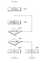
- FIG. 8 is a flowchart showing a flow of processing executed by the control unit in the third embodiment.
- the vehicle air conditioner 10 is mounted on a vehicle 20 and configured as an apparatus for performing air conditioning in the passenger compartment RM. Prior to the description of the vehicle air conditioner 10, the configuration of the vehicle 20 will be briefly described first.
- FIG. 1 schematically shows only the front portion of the compartment RM of the vehicle 20 in a top view.
- a driver seat 21 that is a right seat and a passenger seat 22 that is a left seat are provided adjacent to each other at a front portion in the passenger compartment RM.
- FIG. 1 shows a driver M1 seated in the driver seat 21 and a passenger M2 seated in the passenger seat 22.
- Reference numeral 24 denotes a steering handle.
- An instrument panel 23 is provided further forward of the driver seat 21 and the passenger seat 22.
- a blowout port 213 is formed at the center of the instrument panel 23 in the left-right direction.
- the air outlet 213 is an outlet of air adjusted in temperature by the vehicle air conditioner 10, that is, air-conditioned air. Air-conditioning air is blown out toward the rear side from the air outlet 213, whereby air-conditioning in the passenger compartment RM is performed.
- the configuration of the vehicle air conditioner 10 will be described with reference to FIG.
- the vehicle air conditioner 10 includes a control unit 100, an air conditioning mechanism unit 200, an IR sensor 310, a camera 400, and an internal air temperature sensor 500.
- the control unit 100 is a device for controlling the overall operation of the vehicle air conditioner 10.
- the control unit 100 is configured as a computer system having a CPU, a ROM, a RAM, and the like. Signals from various sensors provided in the vehicle 20 such as an IR sensor 310 described later are input to the control unit 100.
- the control unit 100 controls operations of the air conditioning mechanism unit 200, the sensor driving device 320, and the like based on signals input from various sensors. Thereby, the air conditioning in the passenger compartment RM by the vehicle air conditioner 10 is appropriately performed.
- the air conditioning mechanism 200 is a mechanism for performing air conditioning in the passenger compartment RM.
- the air-conditioning mechanism unit 200 includes a refrigeration cycle (not shown), and adjusts the temperature of the conditioned air blown from the outlet 213 by the refrigeration cycle.
- the air conditioning mechanism unit 200 includes a case 201 that forms an outer shell.
- the case 201 forms an air passage that guides air into the passenger compartment RM, which is the air-conditioning target space.
- an inside air inlet 202 for sucking air (inside air) from the inside of the passenger compartment RM and an outside air inlet 203 for sucking air (outside air) from the outside of the passenger compartment RM are formed.
- the case 201 is provided with an inlet opening / closing door 204 that selectively opens and closes each inlet (202, 203). By the operation of the suction opening / closing door 204, the inside air circulation mode and the outside air circulation mode are switched.
- the operation of the suction opening / closing door 204 is controlled by a drive signal output from the control unit 100.
- a blower 205 as a blower means for blowing air into the passenger compartment RM is disposed on the downstream side of the air flow of the suction opening / closing door 204.
- the blower 205 has a centrifugal fan 205a and a fan motor 205b.
- the number of rotations of the fan motor 205b, that is, the amount of air sent toward the passenger compartment RM is controlled by a drive signal output from the control unit 100.
- An evaporator 206 is disposed on the downstream side of the air flow of the blower 205.
- the evaporator 206 is a heat exchanger that exchanges heat between the refrigerant flowing through the evaporator 206 and the air sent by the blower 205.
- the evaporator 206 constitutes a vapor compression refrigeration cycle together with a compressor, a condenser, an expansion valve, and the like (not shown).
- a heater core 207 for heating the air cooled by the evaporator 206 is disposed on the downstream side of the air flow of the evaporator 206.
- the heater core 207 of this embodiment is a heat exchanger that heats air using cooling water of an engine (not shown) of the vehicle 20 as a heat source.
- a cold air bypass passage 208 is formed in which the air that has passed through the evaporator 206 flows through the heater core 207.
- the temperature of the conditioned air mixed on the downstream side of the air flow between the heater core 207 and the cold air bypass passage 208 varies depending on the air volume ratio of the air passing through the heater core 207 and the air passing through the cold air bypass passage 208.
- an air mix door 209 is disposed at a position downstream of the evaporator 206 in the air flow and on the inlet side of the heater core 207 and the cold air bypass passage 208.
- the air mix door 209 continuously changes the air volume ratio of the cold air flowing into the heater core 207 and the cold air bypass passage 208, and functions as a temperature adjusting means together with the evaporator 206 and the heater core 207.
- the cold air bypass passage 208 is completely closed by the air mix door 209, the temperature of the conditioned air blown into the passenger compartment RM becomes the highest state (MAXHOT).
- the temperature of the conditioned air blown into the passenger compartment RM becomes the lowest state (MAXCOOL).
- the opening degree of the air mix door 209 is controlled by a control signal output from the control unit 100.
- a face opening 211 and a foot opening 221 are provided at the most downstream part of the air-conditioned air flow of the case 201.
- the face opening 211 communicates with a blowout port 213 (see FIG. 1) formed in the instrument panel 23 via the face duct 210.
- the foot opening 221 communicates with the foot outlet 223 via the foot duct 220.
- the foot air outlet 223 is an air outlet that is formed to blow air-conditioned air toward the feet of the passenger.
- a face door 212 that opens and closes the face opening 211 and a foot door 222 that opens and closes the foot opening 221 are arranged on the upstream side of the air flow of the openings (211 and 221).
- the face door 212 and the foot door 222 are blowing mode doors that switch the blowing state of air into the passenger compartment RM.
- the opening / closing operations of the face door 212 and the foot door 222 are controlled by a control signal output from the control unit 100.
- the IR sensor 310 is installed at the center of the upper surface of the instrument panel 23 in the left-right direction.
- the IR sensor 310 is a sensor that detects the surface temperature of an object in the passenger compartment RM based on radiation from the object.
- the “object” here includes, for example, the body of an occupant, the glass of the window of the vehicle 20, a sheet, and the like.
- the IR sensor 310 is provided as a temperature sensor for detecting the surface temperature of an occupant riding the vehicle 20 and appropriately performing air conditioning based on the surface temperature.
- the surface temperature detected by the IR sensor 310 is input to the control unit 100.
- the sensor driving device 320 is a driving device for changing the direction of the IR sensor 310.
- the IR sensor 310 is attached to the upper surface of the instrument panel 23 via the sensor driving device 320.
- the sensor driving device 320 operates and the orientation of the IR sensor 310 is changed, the position of the region where the surface temperature is detected by the IR sensor 310 (hereinafter referred to as “detected region”) changes.
- the operation of the sensor driving device 320 is controlled by a control signal output from the control unit 100.
- a range in which the surface temperature can be detected at once by the IR sensor 310 is shown as a range RG1.
- a relatively narrow-angle IR sensor 310 is used. Since the range RG1 in which the surface temperature can be detected at a time by the IR sensor 310 is narrow, the surface temperatures of all passengers (driver M1, passenger M2, etc.) cannot be detected at the same time.
- the surface temperature of each occupant is sequentially detected by changing the direction of the IR sensor 310 by the operation of the sensor driving device 320.
- the sensor driving device 320 is configured to detect the surface temperature of each part in the passenger compartment RM by periodically swinging the IR sensor 310 left and right.
- the entire range in which the surface temperature can be detected by the peristalsis of the IR sensor 310 is shown as a range RG0.
- the direction of the range RG1 changes within the range RG0. That is, the position of the detected area moves left and right within the range RG0.
- a part of the surface of the driver M1 is a detected area.
- the range RG0 is set as a range including the surfaces of all seated passengers.
- the IR sensor 310 may be installed at a location higher than the upper surface of the instrument panel 23, for example, an overhead console (not shown) on the ceiling.
- the installation location of the IR sensor 310 is preferably a location where radiation (infrared rays) from the surface of each passenger can reach directly.
- the camera 400 is a CCD camera that captures the face of the driver M1 and converts it into image data.
- the camera 400 is installed on the upper surface of the instrument panel 23, but may be installed at other positions.
- the generation of image data by the camera 400 is repeatedly performed every time a predetermined period elapses. Image data generated by the camera 400 is input to the control unit 100.
- the inside temperature sensor 500 is a temperature sensor for measuring the temperature inside the passenger compartment RM.
- the inside air temperature sensor 500 is provided at a part of the instrument panel 23, but may be provided at another position.
- the temperature in the passenger compartment RM measured by the internal temperature sensor 500 is input to the control unit 100.
- the control unit 100 determines the air volume of the conditioned air blown from the air outlet 213, Adjust the temperature.
- the control unit 100 also adjusts the direction in which the conditioned air is blown by controlling the operation of a louver (not shown) provided at the blowout port 213.
- control is performed such that a low-temperature conditioned air is intensively applied to the occupant.
- control is performed such that low-temperature conditioned air is concentrated on the part.
- the temperature distribution in the passenger compartment RM changes every moment according to, for example, the intensity and direction of incident sunlight, the temperature of the conditioned air, the blowing direction, and the like. For this reason, from the viewpoint of accurately obtaining the temperature distribution, it is desirable that the speed of the IR sensor 310 be as high as possible and that the peristaltic period be as short as possible.
- the IR sensor 310 moves at a position relatively close to the driver M1, the movement becomes annoying and the driver M1 may feel visually troublesome.
- the greater the peristaltic speed of the IR sensor 310 the greater the operating sound of the sensor driving device 320, which may be perceived annoyingly by the driver M1.
- the IR sensor 310 is not always peristally oscillated at a constant period, but the peristaltic action is changed to make the driver M1 feel troublesome. It is the composition which prevents.
- FIG. 3 A series of processes shown in FIG. 3 is repeatedly executed by the control unit 100 every time a predetermined period elapses.
- the first step S01 it is determined whether the heat load in the passenger compartment RM is large.
- the state where the “heat load is large” as used herein means that the air conditioning is performed with the maximum performance (or close) of the vehicle air conditioner 10 because the temperature in the passenger compartment RM is very high or very low. It is a state. For example, when the target blowing temperature is set to 50 ° C. or higher, or when the target blowing temperature is set to 0 ° C. or less, it is determined that the thermal load is large.
- an aspect in which the magnitude of the thermal load is determined based on the opening degree of the air mix door 209 may be employed.
- the cold air bypass passage 208 is completely closed by the air mix door 209 (MAXHOT) or when the flow rate of air passing through the heater core 207 is zero by the air mix door 209 (MAXCOOL). It may be determined that the heat load is large.
- step S01 If it is determined in step S01 that the heat load is large, the process proceeds to step S02.
- step S02 a control signal is transmitted from the control unit 100 to the sensor driving device 320, and the peristalsis of the IR sensor 310 is stopped.
- step S02 unnecessary peristaltic motion is stopped to prevent the driver M1 from feeling troublesome.
- step S03 the operation parameter of the peristaltic operation is determined.
- the operation parameter here is a peristaltic period of the IR sensor 310.
- step S03 after the processes shown in FIGS. 4, 5, and 6 are performed in parallel with each other, an optimal peristaltic cycle is determined.
- the rate of change of the surface temperature of a specific occupant is calculated.
- the “change rate” here is a change rate of the surface temperature of the occupant that is repeatedly acquired by the IR sensor 310 at each processing cycle, and the occupant's surface temperature acquired this time from the surface temperature of the occupant acquired this time It is a value (temperature change amount) obtained by subtracting the surface temperature. A value converted into the amount of change in surface temperature per unit time may be used as the “change rate”.
- step S12 it is determined whether or not the calculated change rate is small. Specifically, when the rate of change is below a predetermined threshold, it is determined that the rate of change is small. If it is determined that the rate of change is small, the process proceeds to step S14. In step S14, the peristaltic cycle is set to a longer value T12. The value T12 is stored in advance in the ROM of the control unit 100 as the value of the peristaltic period set when the rate of change is small.
- step S14 the peristaltic cycle is set to a longer value T12 as described above. As a result, the peristaltic operation of the IR sensor 310 can be suppressed without impairing the comfort of air conditioning in the passenger compartment RM.
- step S14 when step S14 is performed, the actual peristaltic period of the IR sensor 310 is not changed. That is, the peristaltic operation of the IR sensor 310 is not changed at this point.
- the peristaltic period value T12 set in step S14 is set as one of peristaltic period candidates.
- step S13 the peristaltic cycle is set to a shorter value T11.
- the value T11 is stored in advance in the ROM of the control unit 100 as a value of the peristaltic period set when the change rate is not small (large).
- the value T11 is smaller than the value T12 set in step S14.
- step S13 the peristaltic period is set to a shorter value T11 as described above. As a result, the temperature distribution in the passenger compartment RM can be accurately measured, and the air conditioning in the passenger compartment RM can be made comfortable.
- step S13 when step S13 is performed, the actual peristaltic period of the IR sensor 310 is not changed. That is, as in step S14, the peristaltic operation of the IR sensor 310 is not changed at this point.
- the peristaltic period value T11 set in step S13 is set as one of peristaltic period candidates.
- step S21 it is determined whether or not the vehicle 20 is traveling.
- the vehicle 20 is traveling if the traveling speed of the vehicle 20 is greater than 0 km / h, and it is determined that the vehicle 20 is not traveling (stopped) when the traveling speed is 0 km / h. It is determined that the vehicle 20 is traveling even when the vehicle 20 is traveling backward toward the rear side. If it is determined that the vehicle 20 is traveling, the process proceeds to step S22.
- step S22 it is determined whether or not the vehicle 20 is traveling straight.
- the vehicle 20 is traveling along a road and the steering angle is relatively small, it is determined that the vehicle 20 is traveling straight.
- the vehicle 20 is making a right turn or a left turn and the steering angle is relatively large, it is determined that the vehicle 20 is not traveling straight.
- the above determination may be made based on whether or not the steering angle of the vehicle 20 is within a predetermined range.
- step S23 the peristaltic cycle is set to a longer value T14.
- the value T14 is stored in advance in the ROM of the control unit 100 as a value of the peristaltic cycle that is set while the vehicle 20 is traveling straight ahead.
- the driver's attention to the front of the M1 tends to be relatively distracting. For this reason, when the IR sensor 310 swings greatly during straight traveling, the driver M1 tends to feel anxious about the operation of the IR sensor 310. Further, when the vehicle 20 is traveling straight ahead, the direction and size of sunlight entering the passenger compartment RM is unlikely to change, so the temperature distribution in the passenger compartment RM is relatively stable. For this reason, even if the peristaltic period of the IR sensor 310 is long, the temperature distribution in the passenger compartment RM can be accurately grasped to some extent.
- step S23 the peristaltic period is set to a longer value T14 as described above.
- the peristaltic operation of the IR sensor 310 can be suppressed without impairing the comfort of air conditioning in the passenger compartment RM.
- step S23 when step S23 is performed, the actual peristaltic period of the IR sensor 310 is not changed. That is, the peristaltic operation of the IR sensor 310 is not changed at this point.
- the peristaltic period value T14 set in step S23 is set as one of peristaltic period candidates.
- step S24 it is determined whether or not the line of sight of the driver M1 is facing the IR sensor 310. Such determination is performed by analyzing image data generated by the camera 400. That is, the camera 400 functions as a line-of-sight detection unit that detects a direction in which the line of sight of the driver M1 is facing (hereinafter also referred to as “line-of-sight direction”).
- step S23 If the line-of-sight direction is the direction toward the IR sensor 310, the process proceeds to step S23.
- the driver M1 looks directly at the IR sensor 310, when the IR sensor 310 swings greatly, the driver M1 tends to feel the operation of the IR sensor 310 bothersome. For this reason, in step S23, the peristaltic cycle is set to a longer value T14 as already described.
- step S24 when the line-of-sight direction is not the direction toward the IR sensor 310, the process proceeds to step S25.
- step S25 the peristaltic cycle is set to a shorter value T15.
- the value T15 is stored in advance in the ROM of the control unit 100 as a value of the peristaltic period that is set when the line-of-sight direction is not toward the IR sensor 310.
- the value T15 is smaller than the value T14 set in step S23.
- step S25 the peristaltic period is set to a shorter value T13 as described above. As a result, the temperature distribution in the passenger compartment RM can be accurately measured, and the air conditioning in the passenger compartment RM can be made comfortable.
- step S25 when step S25 is performed, the actual peristaltic period of the IR sensor 310 is not changed. That is, as in step S23 and the like, the peristaltic operation of the IR sensor 310 is not changed at this point.
- the peristaltic period value T13 set in step S25 is set as one of peristaltic period candidates.
- the magnitude of noise in the passenger compartment RM is calculated.
- the magnitude of the noise is calculated by referring to a map created in advance and stored in the ROM based on the vehicle speed, the rotational speed of the internal combustion engine, the rotational speed of the fan motor 205b, the volume setting of the in-vehicle audio, and the like.
- a mode in which the noise in the passenger compartment RM is directly measured by a microphone may be employed.
- step S32 it is determined whether or not the calculated noise level is small. Specifically, when the noise level is below a predetermined threshold, it is determined that the noise level is low. If it is determined that the noise is low, the process proceeds to step S34.
- step S34 the peristaltic cycle is set to a longer value T16.
- the value T16 is stored in advance in the ROM of the control unit 100 as a value of the peristaltic period set when the noise is low.
- step S34 the peristaltic cycle is set to a longer value T16 as described above. As a result, the operating sound of the IR sensor 310 can be reduced.
- step S34 when step S34 is performed, the actual peristaltic period of the IR sensor 310 is not changed. That is, the peristaltic operation of the IR sensor 310 is not changed at this point.
- the peristaltic period value T16 set in step S34 is set as one of peristaltic period candidates.
- step S33 the peristaltic cycle is set to a shorter value T15.
- the value T15 is stored in advance in the ROM of the control unit 100 as a value of the peristaltic cycle that is set when the noise is not small (large).
- the value T15 is smaller than the value T16 set in step S34.
- step S33 the peristaltic cycle is set to a shorter value T15 as described above. As a result, the temperature distribution in the passenger compartment RM can be accurately measured, and the air conditioning in the passenger compartment RM can be made comfortable.
- step S33 the actual peristaltic period of the IR sensor 310 is not changed when step S33 is performed. That is, as in step S34, the peristaltic operation of the IR sensor 310 is not changed at this point.
- the peristaltic period value T15 set in step S33 is set as one of peristaltic period candidates.
- step S03 the processes in FIGS. 4 to 6 are performed in parallel, and three peristaltic cycle candidates are set as a result of each process.
- step S03 the longest of the set peristaltic cycle candidates is determined as the final peristaltic cycle value. Thereafter, the operation of the sensor driving device 320 is controlled so that the IR sensor 310 performs a peristaltic operation in the determined peristaltic cycle.
- the control unit 100 of the vehicle air conditioner 10 changes the operation of the sensor driving device 320 based on the magnitude of the thermal load in the passenger compartment RM, and Change the peristaltic action. Specifically, when the heat load in the passenger compartment RM is large, the operation of the sensor driving device 320 is stopped (step S02 in FIG. 3). That is, when the air conditioning in the passenger compartment RM is being performed at or near the maximum performance of the vehicle air conditioner 10, the unnecessary peristaltic operation of the IR sensor 310 is stopped. For this reason, it is possible to prevent the driver M1 from feeling troublesome without impairing the comfort of air conditioning in the passenger compartment RM.
- control unit 100 changes the operation of the sensor driving device 320 based on the rate of change of the passenger's surface temperature. Specifically, when the rate of change of the surface temperature is small, the period of the peristaltic movement of the IR sensor 310 is made longer than when the rate of change is large (step S14 in FIG. 4). Thereby, it can be set as the state by which the peristaltic operation of IR sensor 310 was suppressed, without impairing the comfort of the air conditioning in vehicle interior RM. As a result, it is possible to prevent the driver M1 from feeling troublesome.
- the operation of the sensor driving device 320 may be changed as described above based on the change rate of the air temperature measured by the internal air temperature sensor 500 instead of the change rate of the surface temperature of the occupant.
- Control unit 100 changes the operation of sensor driving device 320 based on the traveling state of vehicle 20. Specifically, when the vehicle 20 is traveling and traveling straight, the period of the peristaltic movement of the IR sensor 310 is lengthened compared to when it is not (step S23 in FIG. 5).
- the peristaltic operation of the IR sensor 310 can be suppressed without impairing the comfort of air conditioning in the passenger compartment RM. As a result, it is possible to prevent the driver M1 from feeling troublesome.
- the control unit 100 changes the operation of the sensor driving device 320 based on the line-of-sight direction detected by the camera 400. Specifically, when the line-of-sight direction is directed toward the IR sensor 310, the period of the peristaltic movement of the IR sensor 310 is made longer than when the line-of-sight direction is not (step S23 in FIG. 5). Thereby, it is further prevented that the driver M1 is bothered by the peristaltic operation.
- the control unit 100 changes the operation of the sensor driving device 320 based on the level of noise in the passenger compartment RM. Specifically, when the noise in the passenger compartment RM is small, the period of the peristaltic movement of the IR sensor 310 is lengthened compared to when the noise is large (step S34 in FIG. 6). Thereby, the operating sound of the IR sensor 310 can be reduced. As a result, it is possible to prevent the driver M1 from feeling troublesome.
- step S13, S14 of FIG. 4, step S23, S25 of FIG. 5, and step S33, S34 of FIG. 6, the candidate value about the peristaltic period of IR sensor 310 is set.
- a candidate value for the peristaltic amplitude of the IR sensor 310 may be set.
- step S13 in FIG. 4, step S25 in FIG. 5, and step S33 in FIG. 6, the peristaltic amplitude is not set to a shorter value, but the peristaltic amplitude is set to a larger value. Also good. Further, in step S14 of FIG. 4, step S23 of FIG. 5, and step S34 of FIG. 6, the peristaltic period is not set to a longer value, but the peristaltic amplitude is set to a smaller value. Good.
- step S03 of FIG. 3 the smallest one of the three candidates (peristaltic amplitude candidates) set in each process of FIGS. 4 to 6 is determined as the final peristaltic amplitude value.
- the Rukoto Thereafter, the operation of the sensor driving device 320 is controlled so that the IR sensor 310 performs a peristaltic operation with the determined peristaltic amplitude.
- a candidate value for the peristaltic speed may be set instead of the peristaltic period or peristaltic amplitude of the IR sensor 310.
- the peristaltic speed in this case is the angular speed of the IR sensor 310 (and the sensor driving device 320) when performing the peristaltic operation.
- step S13 in FIG. 4, step S25 in FIG. 5, and step S33 in FIG. 6, the peristaltic speed is not set to a shorter value, but the peristaltic speed is set to a larger value. Also good. Further, in step S14 of FIG. 4, step S23 of FIG. 5, and step S34 of FIG. 6, the peristaltic speed is not set to a long value but the peristaltic speed is set to a small value. Good.
- step S03 of FIG. 3 the smallest one of the three candidates (peristal speed candidates) set in each process of FIGS. 4 to 6 is determined as the final peristaltic speed value.
- the Rukoto Thereafter, the operation of the sensor driving device 320 is controlled so that the IR sensor 310 performs a peristaltic operation at the determined peristaltic speed.
- the peristaltic period or the like is not always automatically set by the control unit 100, but may be configured such that the driver M1 can arbitrarily change them.
- the driver M1 may operate the touch panel to change the peristaltic period or the like, or may change the peristaltic period or the like according to the voice of the driver M1.
- the second embodiment will be described.
- the second embodiment is different from the first embodiment in the content of the process performed to set the peristaltic period candidate value according to the rate of change of the surface temperature (that is, the process of FIG. 4 in the first embodiment).
- Other processes and configurations are the same as those in the first embodiment.
- the series of processing shown in FIG. 4 selects one value from the two values T11 and T12 prepared in advance according to the obtained change rate of the surface temperature, and swings it.
- the process is set as a candidate value for the cycle.
- the peristaltic cycle candidate value is selected and set from values that can be continuously changed.
- FIG. 7 shows the relationship between the change rate and the peristaltic period in this embodiment.
- the horizontal axis in the graph of FIG. 7 represents a temperature change obtained by subtracting the surface temperature of the occupant acquired last time from the surface temperature of the occupant acquired this time. That is, it is the same as the “change rate” calculated in step S22 of FIG.
- the vertical axis in the graph of FIG. 7 is a value set as a peristaltic cycle candidate value.
- the peristaltic cycle candidate value is set to the largest value T20.
- the peristaltic cycle candidate value is set to a smaller value as the absolute value of the temperature change becomes smaller.
- the peristaltic cycle is set to the smallest value T10 regardless of the temperature change.
- the peristaltic period candidate value is set to a larger value as the temperature change becomes larger.
- the peristaltic cycle is set to the largest value T20 without depending on the temperature change.
- the peristaltic cycle candidate value is appropriately set in the range from the value T10 to the value T20 according to the acquired value of the temperature change. If the correspondence relationship as shown in FIG. 7 is set in advance, the peristaltic cycle candidate value can be set more appropriately.
- the candidate value for the peristaltic speed may be set instead of the candidate value for the peristaltic period according to the acquired value of the temperature change.
- the vertical axis in FIG. 7 may be set as a peristaltic speed, and the relationship between the change rate and the peristaltic speed may be set in advance as shown in FIG.
- the third embodiment will be described.
- the contents of the process performed in step S24 in FIG. 5 are different from those in the first embodiment, and other processes and configurations are the same as those in the first embodiment.
- step S24 of FIG. 8 a series of processing shown in FIG. 8 is performed instead of step S24 of FIG. If it is determined in step S21 in FIG. 5 that the vehicle 20 is not traveling, or if it is determined in step S22 in FIG. 5 that the vehicle 20 is not traveling straight, the processing in step S241 in FIG. Is done. In step S241, a timer included in the control unit 100 is reset and measurement of elapsed time is started.
- step S242 the number of times the driver M1's line of sight faces the IR sensor 310 after the process of step S241 is performed is counted.
- the determination as to whether the line of sight of the driver M1 faces the IR sensor 310 and the count of the number of times are performed by analyzing the image data generated by the camera 400.
- step S243 the timer of the control unit 100 is referred to and it is determined whether or not a predetermined period has elapsed since the process of step S241 was performed. If the predetermined period has not elapsed, the process of step S242 is executed again. If the predetermined period has elapsed, the process proceeds to step S244.
- step S244 it is determined whether or not the number of times counted in step S242 exceeds a predetermined threshold value.
- a predetermined threshold value the number of times that the driver's line of sight of the M1 has turned to the IR sensor 310 (hereinafter also referred to as “count value”) after the start of the process of step S241 until the predetermined period elapses is a predetermined threshold. It is determined whether or not If the count value exceeds the threshold value, the process proceeds to step S246. In step S246, the count value is reset. Thereafter, the process of step S23 in FIG. 5 is performed. That is, the peristaltic cycle candidate value is set to the longer value T14.
- step S244 if the count value does not exceed the threshold value, the process proceeds to step S245.
- step S245 the count value is reset. Thereafter, the process of step S25 in FIG. 5 is performed. That is, the peristaltic cycle candidate value is set to a shorter value T13.
- the control unit 100 determines the peristaltic period of the IR sensor 310 when the frequency (count value per predetermined period) in which the line-of-sight direction is directed toward the IR sensor 310 exceeds a predetermined threshold. Lengthen. As a result, when the driver's M1's attention is directed to the IR sensor 310, the peristaltic operation of the IR sensor 310 is suppressed, so that the driver's M1's attention can be diverted from the IR sensor 310. As a result, it is possible to prevent the driver M1 from being careless ahead while driving.
- the candidate value of peristaltic amplitude and peristaltic speed may be set instead of the peristaltic period candidate value as in the case of the first embodiment. That is, when the count value exceeds the threshold value, the peristaltic amplitude candidate value of the IR sensor 310 may be a smaller value, and the peristaltic speed candidate value may be a smaller value.
Landscapes
- Physics & Mathematics (AREA)
- Thermal Sciences (AREA)
- Engineering & Computer Science (AREA)
- Mechanical Engineering (AREA)
- Life Sciences & Earth Sciences (AREA)
- General Life Sciences & Earth Sciences (AREA)
- General Physics & Mathematics (AREA)
- Geophysics (AREA)
- Air-Conditioning For Vehicles (AREA)
Abstract
車両用空調装置(10)は、物体の表面温度を、当該物体からの輻射に基づいて検知する温度検知部(310)と、温度検知部(310)によって表面温度が検知される領域、である被検知領域の位置を変化させるよう、温度検知部(310)を搖動させる搖動機構部(320)と、搖動機構部(320)の動作を制御する制御部(100)と、を備える。 制御部(100)は、車室内における熱負荷の大きさに基づいて搖動機構部(320)の動作を変化させる。
Description
本出願は、2016年1月15日に出願された日本国特許出願2016-5968号に基づくものであって、その優先権の利益を主張するものであり、その特許出願の全ての内容が、参照により本明細書に組み込まれる。
本開示は、車両に備えられる車両用空調装置に関する。
乗員の表面温度を赤外線センサによって測定し、当該表面温度に基づいて空調制御を行う車両用空調装置が知られている。例えば下記特許文献1に記載の車両用空調装置では、吹出口に設けられたスイングルーバーに赤外線センサを配置しており、当該赤外線センサによって乗員の表面温度を算出している。
このような構成においては、スイングルーバーの搖動に伴って赤外線センサの方向が一定の範囲で周期的に変化する。つまり、全ての乗員の表面温度を一度に且つ同時に測定するのではなく、局所的な範囲を測定しながら、当該範囲を徐々に移動させて行くことによって全体の温度分布を検知する構成となっている。このため、検知範囲が比較的狭い安価な赤外線センサを用いながらも、乗員を含む広範囲の温度測定を行うことが可能である。
赤外線センサは、運転者を含む各乗員からの輻射(赤外線)が直接到達し得る位置に配置される。このため、上記特許文献1に記載されているように、運転者の前方側となる位置であり、且つ運転者に比較的近い位置に赤外線センサが配置されることが多い。このような位置において赤外線センサの搖動が行われると、運転者にとっては、赤外線センサの搖動やそれに伴う動作音が煩わしく感じられてしまうことがある。
本開示はこのような課題に鑑みてなされたものであり、その目的は、温度検知部を搖動させる構成としながらも、当該搖動が運転者に煩わしく感じられてしまうことを抑制することのできる車両用空調装置を提供することにある。
本開示に係る車両用空調装置は、物体の表面温度を、当該物体からの輻射に基づいて検知する温度検知部(310)と、温度検知部によって表面温度が検知される領域、である被検知領域の位置を変化させるよう、温度検知部を搖動させる搖動機構部(320)と、搖動機構部の動作を制御する制御部(100)と、を備える。制御部は、車室内における熱負荷の大きさに基づいて搖動機構部の動作を変化させる。
車室内の熱負荷が大きいときには、車室内の気温が高すぎる又は低すぎる状態となっている。このため、例えば高温部分のみを集中的に冷却するようなきめ細かな空調は行われることがなく、空調は最大の性能で行われる。つまり、熱負荷が大きいときには、赤外線センサによって車室内における全体の温度分布を取得する必要性は小さいということができる。そこで、温度検知部の搖動を常に行うのではなく、例えば車室内の熱負荷が小さいときにのみ限定的に行うこととすれば、空調の快適性を損なうことなく、運転者に与える煩わしさを可能な限り抑制することができる。
上記構成の車両用空調装置では、搖動機構部の動作、すなわち温度検知部の搖動を、車室内の熱負荷の大きさに基づいて変化させる。これにより、空調の快適性を損なうことなく、且つ運転者に煩わしい思いをさせない範囲で、温度検知部の搖動を適切に行うことが可能となる。
本開示によれば、温度検知部を搖動させる構成としながらも、当該搖動が運転者に煩わしく感じられてしまうことを抑制することのできる車両用空調装置が提供される。
以下、添付図面を参照しながら本実施形態について説明する。説明の理解を容易にするため、各図面において同一の構成要素に対しては可能な限り同一の符号を付して、重複する説明は省略する。
第1実施形態に係る車両用空調装置10は、車両20に搭載され、車室RM内の空調を行うための装置として構成されている。車両用空調装置10の説明に先立ち、先ず車両20の構成について簡単に説明する。
図1には、車両20の車室RMのうち前方側部分のみが上面視で模式的に示されている。車室RM内の前方側部分には、右側の座席である運転席21と、左側の座席である助手席22とが、互いに隣り合うように設けられている。図1には、運転席21に着座している運転者M1と、助手席22に着座している同乗者M2とが示されている。符号24が付されているのはステアリングハンドルである。
運転席21及び助手席22の更に前方側には、インストルメントパネル23が設けられている。インストルメントパネル23のうち左右方向における中央部には、吹き出し口213が形成されている。吹き出し口213は、車両用空調装置10によって温度調整された空気、すなわち空調風の出口である。吹き出し口213から後方側に向けて空調風が吹き出されることにより、車室RM内の空調が行われる。
引き続き図1を参照しながら、車両用空調装置10の構成について説明する。車両用空調装置10は、制御部100と、空調機構部200と、IRセンサ310と、カメラ400と、内気温センサ500と、を備えている。
制御部100は、車両用空調装置10の全体の動作を制御するための装置である。制御部100は、CPU、ROM、RAM等を有するコンピュータシステムとして構成されている。制御部100には、後述のIRセンサ310等、車両20に設けられた各種センサからの信号が入力されている。制御部100は、各種センサから入力された信号に基づいて、空調機構部200やセンサ駆動装置320等の動作を制御する。これにより、車両用空調装置10による車室RM内の空調が適切に行われる。
空調機構部200は、車室RM内の空調を行うための機構部分である。空調機構部200は不図示の冷凍サイクルを備えており、吹き出し口213から吹き出される空調風の温度を当該冷凍サイクルによって調整する。
空調機構部200の構成について、図2を参照しながら説明する。空調機構部200は、外殻を構成するケース201を有している。このケース201は、空調対象空間である車室RM内へ空気を導く空気通路を構成している。ケース201の空気流れ最上流部には、車室RMの内部から空気(内気)を吸入する内気吸入口202と、車室RMの外部から空気(外気)を吸入する外気吸入口203とが形成されている。また、ケース201には、それぞれの吸入口(202、203)を選択的に開閉する吸入口開閉ドア204が設けられている。吸入口開閉ドア204の動作により、内気循環モードと外気循環モードとが切り換えられる。吸入口開閉ドア204の動作は、制御部100から出力される駆動信号により制御される。
吸入口開閉ドア204の空気流れ下流側には、車室RM内へ空気を送風する送風手段としての送風機205が配置されている。送風機205は、遠心ファン205aと、ファンモータ205bとを有している。ファンモータ205bの回転数、すなわち車室RM内に向けて送り込まれる風量は、制御部100から出力される駆動信号により制御される。
送風機205の空気流れ下流側には蒸発器206が配置されている。蒸発器206は、その内部を流通する冷媒と、送風機205により送り込まれた空気とを熱交換させる熱交換器である。蒸発器206は、図示しない圧縮機、凝縮器、膨張弁等と共に蒸気圧縮式の冷凍サイクルを構成するものである。
蒸発器206の空気流れ下流側には、蒸発器206にて冷却された空気を加熱するヒータコア207が配置されている。本実施形態のヒータコア207は、車両20のエンジン(不図示)の冷却水を熱源として空気を加熱する熱交換器である。また、蒸発器206の空気流れ下流側には、蒸発器206通過後の空気を、ヒータコア207を迂回して流す冷風バイパス通路208が形成されている。
ここで、ヒータコア207および冷風バイパス通路208の空気流れ下流側にて混合される空調風の温度は、ヒータコア207を通過する空気および冷風バイパス通路208を通過する空気の風量割合によって変化する。
このため、蒸発器206の空気流れ下流側であって、ヒータコア207および冷風バイパス通路208の入口側となる位置には、エアミックスドア209が配置されている。このエアミックスドア209は、ヒータコア207および冷風バイパス通路208へ流入する冷風の風量割合を連続的に変化させるもので、蒸発器206およびヒータコア207と共に温度調整手段として機能する。エアミックスドア209によって冷風バイパス通路208が完全に閉じられると、車室RM内に吹き出される空調風の温度が最も高い状態(MAXHOT)となる。また、エアミックスドア209によって冷風バイパス通路208が全開とされ、ヒータコア207を通過する空気の流量が0になると、車室RM内に吹き出される空調風の温度が最も低い状態(MAXCOOL)となる。エアミックスドア209の開度は、制御部100から出力される制御信号によって制御される。
ケース201の空調風流れ最下流部には、フェイス開口部211およびフット開口部221が設けられている。フェイス開口部211は、フェイスダクト210を介して、インストルメントパネル23に形成された吹き出し口213(図1を参照)に連通している。フット開口部221は、フットダクト220を介してフット吹出口223に連通している。フット吹出口223は、乗員の足元に向けて空調風を吹き出すために形成された吹き出し口である。
そして、上記各開口部(211、221)の空気流れ上流側には、フェイス開口部211を開閉するフェイスドア212と、フット開口部221を開閉するフットドア222とが配置されている。フェイスドア212及びフットドア222は、車室RM内への空気の吹出状態を切り替える吹出モードドアである。フェイスドア212及びフットドア222のそれぞれの開閉動作は、制御部100から出力される制御信号によって制御される。
図1に戻って説明を続ける。IRセンサ310は、インストルメントパネル23の上面のうち、左右方向における中央となる位置に設置されている。IRセンサ310は、車室RM内にある物体の表面温度を、当該物体からの輻射に基づいて検知するセンサである。ここでいう「物体」には、例えば乗員の体や、車両20の窓のガラス、シート等が含まれる。IRセンサ310は、車両20に乗っている乗員の表面温度を検知し、当該表面温度に基づいて空調を適切に行うための温度センサとして設けられている。IRセンサ310によって検知された表面温度は、制御部100に入力される。
センサ駆動装置320は、IRセンサ310の向きを変更するための駆動装置である。IRセンサ310は、このセンサ駆動装置320を介してインストルメントパネル23の上面に取り付けられている。センサ駆動装置320が動作し、IRセンサ310の向きが変更されると、IRセンサ310によって表面温度が検知される領域(以下、「被検知領域」と称する)の位置が変化する。センサ駆動装置320の動作は、制御部100から出力される制御信号によって制御される。
図1では、IRセンサ310によって表面温度を一度に検知し得る範囲が、範囲RG1として示されている。本実施形態では、IRセンサ310として比較的狭角のものが用いられている。IRセンサ310によって表面温度を一度に検知し得る範囲RG1が狭いので、全ての乗員(運転者M1や同乗者M2など)の表面温度を一度に且つ同時に検知することはできない。
そこで、本実施形態では、センサ駆動装置320の動作によりIRセンサ310の向きを変化させて行くことで、それぞれの乗員の表面温度を順に検知して行くように構成されている。具体的には、センサ駆動装置320がIRセンサ310を周期的に左右に搖動させることで、車室RM内における各部の表面温度を検知して行くような構成となっている。
図1では、IRセンサ310の搖動によって表面温度を検知し得る範囲の全体が、範囲RG0として示されている。IRセンサ310が搖動すると、範囲RG1の向きが範囲RG0の中で変化していく。つまり、被検知領域の位置が、範囲RG0の中で左右に移動していく。図1に示されている状態においては、運転者M1の表面の一部が被検知領域となっている。範囲RG0は、着座している全ての乗員の表面を含むような範囲として設定されている。
尚、IRセンサ310は、インストルメントパネル23の上面よりも高い場所、例えば天井にあるオーバーヘッドコンソール(不図示)に設置されてもよい。IRセンサ310の設置場所は、各乗員の表面からの輻射(赤外線)が直接到達し得るような場所とすることが好ましい。
カメラ400は、運転者M1の顔を撮影して画像データに変換するCCDカメラである。カメラ400は、インストルメントパネル23の上面に設置されているのであるが、他の位置に設置されてもよい。カメラ400による画像データの生成は、所定の周期が経過する毎に繰り返し行われる。カメラ400によって生成された画像データは、制御部100へと入力される。
内気温センサ500は、車室RM内の気温を計測するための温度センサである。内気温センサ500は、インストルメントパネル23の一部に設けられているのであるが、他の位置に設けられていてもよい。内気温センサ500によって計測された車室RM内の気温は、制御部100へと入力される。
制御部100は、IRセンサ310によって計測された各乗員の表面温度、及び、内気温センサ500によって計測された車室RM内の気温に基づいて、吹き出し口213から吹き出される空調風の風量や温度を調整する。また、制御部100は、吹き出し口213に設けられたルーバー(不図示)の動作を制御することで、空調風が吹き出される方向の調整をも行う。
例えば夏期において、途中から乗り込んできた乗員の表面温度が高くなっているときには、低温の空調風を当該乗員に集中的に当てるような制御が行われる。また、一部の乗員に直射日光が当たっており、その部分が局所的に高温となっているときには、低温の空調風を当該部分に集中的に当てるような制御が行われる。このように、IRセンサ310によって計測された温度分布に基づいて適切な空調を行うことで、各乗員が感じる温熱感をそれぞれ快適なものとすることが可能となっている。
車室RM内の温度分布は、例えば入射する日光の強さや向き、空調風の温度や吹き出し方向等に応じて刻一刻と変化して行く。このため、温度分布を正確に取得するという観点からは、IRセンサ310の搖動の速度は可能な限り大きい方が望ましく、搖動周期は可能な限り短い方が望ましい。
しかしながら、運転者M1に、比較的近い位置においてIRセンサ310が動くと、その動きが目障りとなり、運転者M1にとっては視覚的に煩わしく感じられてしまうことがある。また、IRセンサ310の搖動の速度が大きくなるほど、センサ駆動装置320の動作音も大きくなるので、運転者M1にとっては聴覚的にも煩わしく感じられてしまうことがある。
そこで、本実施形態に係る車両用空調装置10では、IRセンサ310を常に一定の周期で搖動させるのではなく、その搖動動作を適宜変更することで、運転者M1に煩わしい思いをさせてしまうことを防止するような構成となっている。
そのために行われる処理の具体的な内容について、図3を参照しながら説明する。図3に示される一連の処理は、所定の周期が経過する毎に、制御部100によって繰り返し実行されている。
最初のステップS01では、車室RM内の熱負荷が大きいかどうかが判定される。ここでいう「熱負荷が大きい」状態とは、車室RM内の気温が非常に高い又は非常に低いことにより、車両用空調装置10の最大性能(又はその近く)で空調が行われるような状態のことである。例えば、目標吹き出し温度が50℃以上に設定されているときや、目標吹き出し温度が0℃以下に設定されているときには、熱負荷が大きいと判定される。
このような態様に替えて、エアミックスドア209の開度に基づいて熱負荷の大きさを判定するような態様であってもよい。この場合、エアミックスドア209により冷風バイパス通路208が完全に閉じられているとき(MAXHOT)や、エアミックスドア209によりヒータコア207を通過する空気の流量が0とされているとき(MAXCOOL)には、熱負荷が大きいと判定されることとしてもよい。
ステップS01において熱負荷が大きいと判定されると、ステップS02に移行する。ステップS02では、制御部100からセンサ駆動装置320へと制御信号が送信され、IRセンサ310の搖動が停止される。
この場合、車両用空調装置10の最大性能又はその近くで空調が行われるので、例えば高温部分のみを集中的に冷却するようなきめ細かな空調は行われない。表面温度の分布に基づいた空調は行われないので、IRセンサ310の搖動動作は不要ということになる。そこで、ステップS02では不要な搖動動作を停止することで、運転者M1に煩わしい思いをさせてしまうことを防止している。
ステップS01において、熱負荷が大きいと判定されなかった場合には、ステップS03に移行する。ステップS03では、搖動動作の動作パラメータが決定される。ここでいう動作パラメータとは、IRセンサ310の搖動周期のことである。
ステップS03では、図4、図5、図6のそれぞれに示される処理が互いに並列に行われた後、最適な搖動周期が決定される。
先ず、図4に示される処理について説明する。最初のステップS11では、特定の乗員(例えば運転者M1)の表面温度の変化率が算出される。ここでいう「変化率」とは、処理周期ごとにIRセンサ310で繰り返し取得される乗員の表面温度、の変化率であって、今回取得された乗員の表面温度から、前回取得された乗員の表面温度を差し引くことによって得られた値(温度変化量)のことである。尚、単位時間あたりにおける表面温度の変化量に換算した値を「変化率」として用いてもよい。
ステップS11に続くステップS12では、算出された変化率が小さいか否かが判定される。具体的には、変化率が所定の閾値を下回っている場合には、変化率が小さいと判定される。変化率が小さいと判定されると、ステップS14に移行する。ステップS14では、搖動周期が長めの値T12に設定される。値T12は、変化率が小さいときに設定される搖動周期の値として、制御部100のROMに予め記憶されているものである。
変化率が小さいときには、車室RM内の温度分布は比較的安定している。このため、IRセンサ310の搖動周期が小さくても、車室RM内の温度分布はある程度正確に把握することができる。そこで、ステップS14では、上記のように搖動周期が長めの値T12に設定される。これにより、車室RM内における空調の快適性を損なうことなく、IRセンサ310の搖動動作が抑制された状態とすることが可能となる。
尚、ステップS14が行われた時点においては、実際におけるIRセンサ310の搖動周期は変更されない。つまり、IRセンサ310の搖動動作はこの時点では変更されない。ステップS14で設定される搖動周期の値T12は、搖動周期の候補の一つとして設定されるものである。
ステップS12において、変化率が小さいと判定されなかった場合には、ステップS13に移行する。ステップS13では、搖動周期が短めの値T11に設定される。値T11は、変化率が小さくない(大きい)ときに設定される搖動周期の値として、制御部100のROMに予め記憶されているものである。値T11は、ステップS14で設定される値T12よりも小さい。
変化率が大きいときには、車室RM内の温度分布は不安定であり、短時間のうちに大きく変化してしまう可能性がある。そこで、ステップS13では、上記のように搖動周期が短めの値T11に設定される。これにより、車室RM内の温度分布を正確に計測し、車室RM内の空調を快適なものとすることが可能となる。
尚、ステップS13が行われた時点においては、実際におけるIRセンサ310の搖動周期は変更されない。つまり、ステップS14の場合と同様に、IRセンサ310の搖動動作はこの時点では変更されない。ステップS13で設定される搖動周期の値T11は、搖動周期の候補の一つとして設定されるものである。
続いて、図5に示される処理について説明する。最初のステップS21では、車両20が走行中であるか否かが判定される。ここでは、車両20の走行速度が0km/hよりも大きければ走行中であると判定され、走行速度が0km/hのときには走行中でない(停車中である)と判定される。尚、車両20が後方側に向かってバック走行しているときにも、走行中であると判定される。車両20が走行中であると判定された場合にはステップS22に移行する。
ステップS22では、車両20が直進しているか否かが判定される。車両20が道なりに走行しており、操舵角が比較的小さくなっているときには、車両20が直進していると判定される。一方、車両20が右折又は左折を行っており、操舵角が比較的大きくなっているときには、車両20が直進していないと判定される。具体的には、車両20の操舵角が所定の範囲内となっているか否かに基づいて、上記のような判定が行われることとすればよい。
車両20が直進している場合には、ステップS23に移行する。ステップS23では、搖動周期が長めの値T14に設定される。値T14は、車両20が直進走行中に設定される搖動周期の値として、制御部100のROMに予め記憶されているものである。
車両20が直進走行しているときには、運転者M1の前方に対する注意力は比較的散漫になりやすい。このため、直進走行時においてIRセンサ310が大きく搖動すると、運転者M1はIRセンサ310の動作が気になってしまい、当該動作を煩わしく感じてしまう傾向がある。更に、車両20が直進走行しているときには、車室RM内に入射する日光の向きや大きさが変化しにくいので、車室RM内の温度分布は比較的安定している。このため、IRセンサ310の搖動周期が長くても、車室RM内の温度分布はある程度正確に把握することができる。
そこで、ステップS23では、上記のように搖動周期が長めの値T14に設定される。これにより、車室RM内における空調の快適性を損なうことなく、IRセンサ310の搖動動作が抑制された状態とすることが可能となる。
尚、ステップS23が行われた時点においては、実際におけるIRセンサ310の搖動周期は変更されない。つまり、IRセンサ310の搖動動作はこの時点では変更されない。ステップS23で設定される搖動周期の値T14は、搖動周期の候補の一つとして設定されるものである。
ステップS21において車両20が走行中でなかった場合、又は、ステップS22において車両20が直進走行中でなかった場合には、ステップS24に移行する。ステップS24では、運転者M1の視線がIRセンサ310を向いているか否か、が判定される。かかる判定は、カメラ400により生成された画像データを解析することによって行われる。つまり、カメラ400は、運転者M1の視線が向いている方向(以下、「視線方向」とも称する)を検知する視線検知部として機能する。
視線方向がIRセンサ310に向かう方向となっている場合には、ステップS23に移行する。この場合、運転者M1がIRセンサ310の方を直接見ているのであるから、IRセンサ310が大きく搖動すると、運転者M1はIRセンサ310の動作を煩わしく感じやすい。このため、ステップS23では、既に述べたように搖動周期が長めの値T14に設定される。
ステップS24において、視線方向がIRセンサ310に向かう方向となっていない場合には、ステップS25に移行する。ステップS25では、搖動周期が短めの値T15に設定される。値T15は、視線方向がIRセンサ310に向かっていないときに設定される搖動周期の値として、制御部100のROMに予め記憶されているものである。値T15は、ステップS23で設定される値T14よりも小さい。
視線方向がIRセンサ310に向かっていないときには、運転者M1がIRセンサ310の方を直接は見ていないのであるから、IRセンサ310の搖動が行われても、運転者M1にとってはさほど気にならない可能性がある。そこで、ステップS25では、上記のように搖動周期が短めの値T13に設定される。これにより、車室RM内の温度分布を正確に計測し、車室RM内の空調を快適なものとすることが可能となる。
尚、ステップS25が行われた時点においては、実際におけるIRセンサ310の搖動周期は変更されない。つまり、ステップS23等の場合と同様に、IRセンサ310の搖動動作はこの時点では変更されない。ステップS25で設定される搖動周期の値T13は、搖動周期の候補の一つとして設定されるものである。
続いて、図6に示される処理について説明する。最初のステップS31では、車室RM内における騒音の大きさが算出される。騒音の大きさは、車速、内燃機関の回転数、ファンモータ205bの回転数、及び車載オーディオのボリューム設定等に基づいて、予め作成されROMに記憶されたマップを参照することにより算出される。このような態様に替えて、車室RM内の騒音を、マイクによって直接測定するような態様としてもよい。
ステップS31に続くステップS32では、算出された騒音の大きさが小さいか否かが判定される。具体的には、騒音の大きさが所定の閾値を下回っている場合には、騒音が小さいと判定される。騒音が小さいと判定されると、ステップS34に移行する。ステップS34では、搖動周期が長めの値T16に設定される。値T16は、騒音が小さいときに設定される搖動周期の値として、制御部100のROMに予め記憶されているものである。
騒音が小さいときには、搖動するIRセンサ310(及びセンサ駆動装置320)の動作音が耳障りなものとなりやすく、運転者M1はその動作音を煩わしく感じやすい。そこで、ステップS34では、上記のように搖動周期が長めの値T16に設定される。これにより、IRセンサ310の動作音が低減された状態とすることが可能となる。
尚、ステップS34が行われた時点においては、実際におけるIRセンサ310の搖動周期は変更されない。つまり、IRセンサ310の搖動動作はこの時点では変更されない。ステップS34で設定される搖動周期の値T16は、搖動周期の候補の一つとして設定されるものである。
ステップS32において、騒音が小さいと判定されなかった場合には、ステップS33に移行する。ステップS33では、搖動周期が短めの値T15に設定される。値T15は、騒音が小さくない(大きい)ときに設定される搖動周期の値として、制御部100のROMに予め記憶されているものである。値T15は、ステップS34で設定される値T16よりも小さい。
車室RM内の騒音が大きいときには、運転者M1は当該騒音に気を取られるので、搖動するIRセンサ310(及びセンサ駆動装置320)の動作音に気が付かない可能性が高い。そこで、ステップS33では、上記のように搖動周期が短めの値T15に設定される。これにより、車室RM内の温度分布を正確に計測し、車室RM内の空調を快適なものとすることが可能となる。
尚、ステップS33が行われた時点においては、実際におけるIRセンサ310の搖動周期は変更されない。つまり、ステップS34の場合と同様に、IRセンサ310の搖動動作はこの時点では変更されない。ステップS33で設定される搖動周期の値T15は、搖動周期の候補の一つとして設定されるものである。
図3に戻って説明を続ける。以上のように、ステップS03では、図4乃至図6の各処理が並列で行われ、それぞれの処理の結果として搖動周期の候補が3つ設定される。ステップS03では、設定された搖動周期の候補のうち最も長いものが、最終的な搖動周期の値として決定される。以降は、決定された搖動周期でIRセンサ310が搖動動作を行うように、センサ駆動装置320の動作が制御されることとなる。
以上に説明したように、本実施形態に係る車両用空調装置10の制御部100は、車室RM内における熱負荷の大きさに基づいてセンサ駆動装置320の動作を変化させ、IRセンサ310の搖動動作を変化させる。具体的には、車室RM内の熱負荷が大きいときにはセンサ駆動装置320の動作を停止させる(図3のステップS02)。つまり、車両用空調装置10の最大性能又はその近くで車室RM内の空調が行われているときに、不要なIRセンサ310の搖動動作が停止される。このため、車室RM内における空調の快適性を損なうことなく、運転者M1に煩わしい思いをさせてしまうことを防止することが可能となっている。
また、制御部100は、乗員の表面温度の変化率に基づいてセンサ駆動装置320の動作を変化させる。具体的には、表面温度の変化率が小さいときには、変化率が大きいときに比べてIRセンサ310の搖動の周期を長くする(図4のステップS14)。これにより、車室RM内における空調の快適性を損なうことなく、IRセンサ310の搖動動作が抑制された状態とすることができる。その結果、運転者M1に煩わしい思いをさせてしまうことが防止される。
尚、乗員の表面温度の変化率ではなく、内気温センサ500で計測された気温の変化率に基づいて、センサ駆動装置320の動作を上記のように変化させることとしてもよい。
制御部100は、車両20の走行状態に基づいてセンサ駆動装置320の動作を変化させる。具体的には、車両20が走行中であり且つ直進しているときには、そうでないときに比べてIRセンサ310の搖動の周期を長くする(図5のステップS23)。
これにより、車室RM内における空調の快適性を損なうことなく、IRセンサ310の搖動動作が抑制された状態とすることができる。その結果、運転者M1に煩わしい思いをさせてしまうことが防止される。
制御部100は、カメラ400によって検知された視線方向に基づいてセンサ駆動装置320の動作を変化させる。具体的には、視線方向がIRセンサ310に向かう方向となっているときには、そうでないときに比べてIRセンサ310の搖動の周期を長くする(図5のステップS23)。これにより、搖動動作によって運転者M1に煩わしい思いをさせてしまうことが更に防止される。
制御部100は、車室RM内における騒音の大きさに基づいてセンサ駆動装置320の動作を変化させる。具体的には、車室RM内における騒音が小さいときには、騒音が大きいときに比べてIRセンサ310の搖動の周期を長くする(図6のステップS34)。これにより、IRセンサ310の動作音が低減された状態とすることができる。その結果、運転者M1に煩わしい思いをさせてしまうことが防止される。
尚、図4のステップS13、S14、図5のステップS23、S25、及び図6のステップS33、S34においては、IRセンサ310の搖動周期についての候補値を設定している。このような態様に替えて、IRセンサ310の搖動振幅についての候補値が設定されることとしてもよい。
具体的には、図4のステップS13、図5のステップS25、図6のステップS33において、搖動周期が短めの値に設定されるのではなく、搖動振幅が大きめの値に設定されることとしてもよい。また、図4のステップS14、図5のステップS23、図6のステップS34においては、搖動周期が長めの値に設定されるのではなく、搖動振幅が小さめの値に設定されることとすればよい。
この場合、図3のステップS03では、図4乃至図6の各処理でそれぞれ設定された3つの候補(搖動振幅の候補)のうち、最も小さいものが、最終的な搖動振幅の値として決定されることとなる。以降は、決定された搖動振幅でIRセンサ310が搖動動作を行うように、センサ駆動装置320の動作が制御されることとなる。
また、IRセンサ310の搖動周期や搖動振幅ではなく、搖動速度についての候補値が設定されることとしてもよい。この場合の搖動速度とは、搖動動作を行う際におけるIRセンサ310(及びセンサ駆動装置320)の角速度のことである。
具体的には、図4のステップS13、図5のステップS25、図6のステップS33において、搖動周期が短めの値に設定されるのではなく、搖動速度が大きめの値に設定されることとしてもよい。また、図4のステップS14、図5のステップS23、図6のステップS34においては、搖動周期が長めの値に設定されるのではなく、搖動速度が小さめの値に設定されることとすればよい。
この場合、図3のステップS03では、図4乃至図6の各処理でそれぞれ設定された3つの候補(搖動速度の候補)のうち、最も小さいものが、最終的な搖動速度の値として決定されることとなる。以降は、決定された搖動速度でIRセンサ310が搖動動作を行うように、センサ駆動装置320の動作が制御されることとなる。
尚、運転者M1がIRセンサ310の動作を煩わしいと感じるかどうかは、個人差によって異なることもある。そこで、搖動周期等が制御部100によって常に自動的に設定されるのではなく、運転者M1がこれらを任意に変更し得るような構成としてもよい。例えば、運転者M1がタッチパネルを操作して搖動周期等を変更し得る構成としてもよく、運転者M1の音声によって搖動周期等を変更し得る構成としてもよい。
第2実施形態について説明する。第2実施形態では、表面温度の変化率に応じて搖動周期の候補値を設定するために行われる処理(すなわち第1実施形態における図4の処理)の内容について第1実施形態と異なっており、他の処理や構成については第1実施形態と同じである。
既に述べたように、図4に示される一連の処理は、取得した表面温度の変化率に応じて、予め用意された2つの値T11、T12の中から1つの値を選択し、これを搖動周期の候補値として設定する処理となっている。これに対し、本実施形態では、搖動周期の候補値を、連続的に変化し得る値の中から選択し設定するような態様となっている。
図7には、本実施形態における変化率と搖動周期との関係が示されている。図7のグラフにおける横軸は、今回取得された乗員の表面温度から、前回取得された乗員の表面温度を差し引くことによって得られた温度変化である。すなわち、図4のステップS22で算出される「変化率」と同じものである。図7のグラフにおける縦軸は、搖動周期の候補値として設定される値である。
図7に示される例では、温度変化(変化率)が-20℃を下回っているときには、搖動周期の候補値は最も大きな値T20に設定される。温度変化が-20℃から-10℃の範囲においては、温度変化の絶対値が小さくなるほど搖動周期の候補値も小さな値に設定される。温度変化が-10℃から10℃の範囲においては、温度変化によることなく搖動周期は最も小さな値T10に設定される。温度変化が10℃から20℃の範囲においては、温度変化が大きくなるほど搖動周期の候補値も大きな値に設定される。温度変化が20℃よりも大きいときには、温度変化によることなく搖動周期は最も大きな値T20に設定される。
このように、本実施形態では、取得された温度変化の値に応じて、搖動周期の候補値が値T10から値T20までの範囲で適宜設定される。図7に示されるような対応関係を予め設定しておけば、搖動周期の候補値をより適切に設定することができる。
尚、取得された温度変化の値に応じて、搖動周期の候補値ではなく搖動速度の候補値が設定されてもよいのは、第1実施形態の場合と同様である。例えば、図7の縦軸を搖動速度とした上で、変化率と搖動速度との関係が図7に示されるようなものとなるように予め設定されてもよい。
第3実施形態について説明する。第3実施形態では、図5のステップS24で行われる処理の内容について第1実施形態と異なっており、他の処理や構成については第1実施形態と同じである。
本実施形態では、図5のステップS24に替えて、図8に示される一連の処理が行われる。図5のステップS21において車両20が走行中ではないと判定された場合、又は、図5のステップS22において車両20が直進走行していないと判定された場合には、図8のステップS241の処理が行われる。ステップS241では、制御部100が内部に有するタイマーがリセットされ、経過時間の計測が開始される。
ステップS241に続くステップS242では、ステップS241の処理が行われた以降において、運転者M1の視線がIRセンサ310を向いた回数がカウントされる。運転者M1の視線がIRセンサ310を向いたかどうかの判定、及びその回数のカウントは、カメラ400により生成された画像データを解析することによって行われる。
ステップS242に続くステップS243では、制御部100のタイマーが参照され、ステップS241の処理が行われてから所定の期間が経過したかどうかが判定される。所定の期間が経過していなければ、ステップS242の処理が再度実行される。所定の期間が経過していれば、ステップS244に移行する。
ステップS244では、ステップS242でカウントされた回数が、所定の閾値を越えているかどうかが判定される。つまり、ステップS241の処理が開始されてから所定の期間が経過するまでの間に、運転者M1の視線がIRセンサ310を向いた回数(以下、「カウント値」とも表記する)が所定の閾値を越えたかどうかが判定される。カウント値が閾値を越えていれば、ステップS246に移行する。ステップS246では、カウント値がリセットされる。その後、図5のステップS23の処理が行われる。つまり、搖動周期の候補値が長めの値T14に設定される。
ステップS244において、カウント値が閾値を越えていなかった場合には、ステップS245に移行する。ステップS245では、カウント値がリセットされる。その後、図5のステップS25の処理が行われる。つまり、搖動周期の候補値が短めの値T13に設定される。
このように、本実施形態においては、制御部100は、視線方向がIRセンサ310に向かう方向となる頻度(所定期間あたりのカウント値)が所定の閾値を越えたときには、IRセンサ310の搖動周期を長くする。これにより、運転者M1の注意がIRセンサ310に向けられているときにはIRセンサ310の搖動動作が抑制された状態となるので、運転者M1の注意をIRセンサ310から逸らすことができる。その結果、運転者M1が運転中に前方不注意となってしまうこと未然に防ぐことができる。
尚、図5のステップS23やステップS25において、搖動周期の候補値ではなく搖動振幅や搖動速度の候補値が設定されてもよいのは、第1実施形態の場合と同様である。つまり、カウント値が閾値を越えたときには、IRセンサ310の搖動振幅の候補値を小さめの値としてもよく、搖動速度の候補値を小さめの値としてもよい。
以上、具体例を参照しつつ本実施形態について説明した。しかし、本開示はこれらの具体例に限定されるものではない。これら具体例に、当業者が適宜設計変更を加えたものも、本開示の特徴を備えている限り、本開示の範囲に包含される。前述した各具体例が備える各要素およびその配置、条件、形状などは、例示したものに限定されるわけではなく適宜変更することができる。前述した各具体例が備える各要素は、技術的な矛盾が生じない限り、適宜組み合わせを変えることができる。
Claims (12)
- 車両(20)に備えられる車両用空調装置(10)であって、
物体の表面温度を、当該物体からの輻射に基づいて検知する温度検知部(310)と、
前記温度検知部によって表面温度が検知される領域、である被検知領域の位置を変化させるよう、前記温度検知部を搖動させる搖動機構部(320)と、
前記搖動機構部の動作を制御する制御部(100)と、を備え、
前記制御部は、車室内における熱負荷の大きさに基づいて前記搖動機構部の動作を変化させる、車両用空調装置。 - 前記制御部は、
前記熱負荷が大きいときには前記搖動機構部の動作を停止させる、請求項1に記載の車両用空調装置。 - 前記制御部は、
乗員の表面温度又は前記車室内の気温、の変化率に基づいて、前記搖動機構部の動作を変化させる、請求項2に記載の車両用空調装置。 - 前記制御部は、
前記変化率が小さいときには、前記搖動機構部における搖動の周期を長くするか、前記搖動機構部における搖動の振幅を小さくするか、もしくは前記搖動機構部における搖動の速度を小さくする、請求項3に記載の車両用空調装置。 - 前記制御部は、
前記車両の走行状態に基づいて前記搖動機構部の動作を変化させる、請求項2に記載の車両用空調装置。 - 前記制御部は、
前記車両が走行中であるときには、前記搖動機構部における搖動の周期を長くするか、前記搖動機構部における搖動の振幅を小さくするか、もしくは前記搖動機構部における搖動の速度を小さくする、請求項5に記載の車両用空調装置。 - 前記制御部は、
前記車両が直進しているときには、前記搖動機構部における搖動の周期を長くするか、前記搖動機構部における搖動の振幅を小さくするか、もしくは前記搖動機構部における搖動の速度を小さくする、請求項5に記載の車両用空調装置。 - 運転者の視線が向いている方向、である視線方向を検知する視線検知部(400)を更に備え、
前記制御部は、
前記視線方向に基づいて前記搖動機構部の動作を変化させる、請求項2に記載の車両用空調装置。 - 前記制御部は、
前記視線方向が前記温度検知部に向かう方向となっているときには、前記搖動機構部における搖動の周期を長くするか、前記搖動機構部における搖動の振幅を小さくするか、もしくは前記搖動機構部における搖動の速度を小さくする、請求項8に記載の車両用空調装置。 - 前記制御部は、
前記視線方向が前記温度検知部に向かう方向となる頻度が所定の閾値を越えたときには、前記搖動機構部における搖動の周期を長くするか、前記搖動機構部における搖動の振幅を小さくするか、もしくは前記搖動機構部における搖動の速度を小さくする、請求項8に記載の車両用空調装置。 - 前記制御部は、
前記車室内における騒音の大きさに基づいて前記搖動機構部の動作を変化させる、請求項2に記載の車両用空調装置。 - 前記制御部は、
前記車室内における騒音が小さいときには、前記搖動機構部における搖動の周期を長くするか、前記搖動機構部における搖動の振幅を小さくするか、もしくは前記搖動機構部における搖動の速度を小さくする、請求項11に記載の車両用空調装置。
Priority Applications (3)
| Application Number | Priority Date | Filing Date | Title |
|---|---|---|---|
| CN201680078811.0A CN108473023B (zh) | 2016-01-15 | 2016-12-01 | 车辆用空调装置 |
| DE112016006238.9T DE112016006238T5 (de) | 2016-01-15 | 2016-12-01 | Fahrzeugklimaanlage |
| US16/068,921 US10675944B2 (en) | 2016-01-15 | 2016-12-01 | Vehicular air conditioner |
Applications Claiming Priority (2)
| Application Number | Priority Date | Filing Date | Title |
|---|---|---|---|
| JP2016005968A JP6493232B2 (ja) | 2016-01-15 | 2016-01-15 | 車両用空調装置 |
| JP2016-005968 | 2016-01-15 |
Publications (1)
| Publication Number | Publication Date |
|---|---|
| WO2017122453A1 true WO2017122453A1 (ja) | 2017-07-20 |
Family
ID=59311145
Family Applications (1)
| Application Number | Title | Priority Date | Filing Date |
|---|---|---|---|
| PCT/JP2016/085786 Ceased WO2017122453A1 (ja) | 2016-01-15 | 2016-12-01 | 車両用空調装置 |
Country Status (5)
| Country | Link |
|---|---|
| US (1) | US10675944B2 (ja) |
| JP (1) | JP6493232B2 (ja) |
| CN (1) | CN108473023B (ja) |
| DE (1) | DE112016006238T5 (ja) |
| WO (1) | WO2017122453A1 (ja) |
Families Citing this family (2)
| Publication number | Priority date | Publication date | Assignee | Title |
|---|---|---|---|---|
| DE102021125409A1 (de) | 2021-09-30 | 2023-03-30 | Ford Global Technologies, Llc | Steuern der Temperatur im Innenraum eines Fahrzeugs |
| DE102022003426A1 (de) | 2022-09-16 | 2024-03-21 | Mercedes-Benz Group AG | Heizsystem eines Fahrzeugs |
Citations (2)
| Publication number | Priority date | Publication date | Assignee | Title |
|---|---|---|---|---|
| JPS63255116A (ja) * | 1987-04-13 | 1988-10-21 | Diesel Kiki Co Ltd | 空気調和装置用熱源体検出装置およびその空気調和装置 |
| JP2005059821A (ja) * | 2003-07-29 | 2005-03-10 | Nissan Motor Co Ltd | 車両用空調装置 |
Family Cites Families (11)
| Publication number | Priority date | Publication date | Assignee | Title |
|---|---|---|---|---|
| JPS59100012A (ja) * | 1982-11-30 | 1984-06-09 | Nippon Denso Co Ltd | カ−エアコン制御装置 |
| US5400964A (en) * | 1993-11-29 | 1995-03-28 | Delco Electronics Corporation | Infra-red comfort sensor |
| JP3952597B2 (ja) | 1997-08-08 | 2007-08-01 | 株式会社デンソー | 車両用空調装置 |
| DE50213116D1 (de) * | 2001-02-15 | 2009-01-29 | Behr Gmbh & Co Kg | Klimaanlage und Vorrichtung zur Regelung des thermischen Komforts in einem Kraftfahrzeug |
| JP4062124B2 (ja) | 2003-02-25 | 2008-03-19 | 株式会社デンソー | 車両用空調装置 |
| US9457639B2 (en) * | 2011-04-27 | 2016-10-04 | Mahle International Gmbh | System and method of providing quick thermal comfort with reduced energy by using directed spot conditioning |
| CN102538155A (zh) * | 2011-12-16 | 2012-07-04 | 浙江兰通空调设备有限公司 | 带乘员数量检测的多区自动空调系统 |
| CN104520683B (zh) * | 2013-05-17 | 2018-05-08 | 松下电器(美国)知识产权公司 | 温度测定装置及温度测定方法 |
| US10272920B2 (en) * | 2013-10-11 | 2019-04-30 | Panasonic Intellectual Property Corporation Of America | Processing method, program, processing apparatus, and detection system |
| JP2015197502A (ja) * | 2014-03-31 | 2015-11-09 | 三菱重工業株式会社 | 画像取得装置 |
| FR3021715B1 (fr) | 2014-05-28 | 2016-05-20 | Pcm | Dispositif de distribution et ensemble de tels dispositifs de distribution |
-
2016
- 2016-01-15 JP JP2016005968A patent/JP6493232B2/ja not_active Expired - Fee Related
- 2016-12-01 WO PCT/JP2016/085786 patent/WO2017122453A1/ja not_active Ceased
- 2016-12-01 CN CN201680078811.0A patent/CN108473023B/zh not_active Expired - Fee Related
- 2016-12-01 DE DE112016006238.9T patent/DE112016006238T5/de not_active Withdrawn
- 2016-12-01 US US16/068,921 patent/US10675944B2/en not_active Expired - Fee Related
Patent Citations (2)
| Publication number | Priority date | Publication date | Assignee | Title |
|---|---|---|---|---|
| JPS63255116A (ja) * | 1987-04-13 | 1988-10-21 | Diesel Kiki Co Ltd | 空気調和装置用熱源体検出装置およびその空気調和装置 |
| JP2005059821A (ja) * | 2003-07-29 | 2005-03-10 | Nissan Motor Co Ltd | 車両用空調装置 |
Also Published As
| Publication number | Publication date |
|---|---|
| US20190016192A1 (en) | 2019-01-17 |
| JP2017124783A (ja) | 2017-07-20 |
| CN108473023A (zh) | 2018-08-31 |
| CN108473023B (zh) | 2021-05-07 |
| DE112016006238T5 (de) | 2018-10-18 |
| US10675944B2 (en) | 2020-06-09 |
| JP6493232B2 (ja) | 2019-04-03 |
Similar Documents
| Publication | Publication Date | Title |
|---|---|---|
| CN103561975B (zh) | 车用空气调节器 | |
| JP2004283403A (ja) | シート空調装置および車両用シート空調装置 | |
| JP6702206B2 (ja) | 車両用空調装置 | |
| JP6493232B2 (ja) | 車両用空調装置 | |
| CN108473021B (zh) | 车辆用空调装置 | |
| JP7031237B2 (ja) | 空調装置 | |
| JP4353053B2 (ja) | 車両用空調装置 | |
| JP4613718B2 (ja) | 車両用空調装置および車両用空調制御方法 | |
| JP2021059234A (ja) | コンバーチブル車両の温調デバイス制御装置 | |
| JP4501643B2 (ja) | 車両用空調装置および車両用空調制御方法 | |
| JP2017177832A (ja) | 車両用空調装置 | |
| JP2000142081A (ja) | 車両用空調装置 | |
| JP2019107991A (ja) | 車両用空調装置 | |
| JP2003252023A (ja) | 空調装置 | |
| JP2004330961A (ja) | 車両用空調装置 | |
| JPH02175413A (ja) | 自動車用空気調和装置におけるモード切り替え装置 | |
| JP2019094022A (ja) | 窓曇り調整システム | |
| JP6702204B2 (ja) | 車両用空調装置 | |
| JP4862441B2 (ja) | 車両用空調装置 | |
| JP4458908B2 (ja) | 車両用空調装置 | |
| JP2005082078A (ja) | 車両用空調装置 | |
| JP7552495B2 (ja) | 車両用空調装置 | |
| JP2010163003A (ja) | 車両用空調装置 | |
| JP2014076682A (ja) | 車両用防曇装置 | |
| JP2006176034A (ja) | 自動車の空気調和方法及び自動車用空気調和装置 |
Legal Events
| Date | Code | Title | Description |
|---|---|---|---|
| 121 | Ep: the epo has been informed by wipo that ep was designated in this application |
Ref document number: 16885056 Country of ref document: EP Kind code of ref document: A1 |
|
| WWE | Wipo information: entry into national phase |
Ref document number: 112016006238 Country of ref document: DE |
|
| 122 | Ep: pct application non-entry in european phase |
Ref document number: 16885056 Country of ref document: EP Kind code of ref document: A1 |