WO2017119249A1 - Substrat multicouche et procédé de fabrication de substrat multicouche - Google Patents
Substrat multicouche et procédé de fabrication de substrat multicouche Download PDFInfo
- Publication number
- WO2017119249A1 WO2017119249A1 PCT/JP2016/087171 JP2016087171W WO2017119249A1 WO 2017119249 A1 WO2017119249 A1 WO 2017119249A1 JP 2016087171 W JP2016087171 W JP 2016087171W WO 2017119249 A1 WO2017119249 A1 WO 2017119249A1
- Authority
- WO
- WIPO (PCT)
- Prior art keywords
- multilayer substrate
- insulator layer
- resin
- insulator
- package component
- Prior art date
Links
Images


Classifications
-
- H—ELECTRICITY
- H05—ELECTRIC TECHNIQUES NOT OTHERWISE PROVIDED FOR
- H05K—PRINTED CIRCUITS; CASINGS OR CONSTRUCTIONAL DETAILS OF ELECTRIC APPARATUS; MANUFACTURE OF ASSEMBLAGES OF ELECTRICAL COMPONENTS
- H05K3/00—Apparatus or processes for manufacturing printed circuits
- H05K3/46—Manufacturing multilayer circuits
Definitions
- the present invention relates to a multilayer substrate and a method for manufacturing the multilayer substrate, and more particularly to a multilayer substrate including a base material on which an insulating layer made of a thermoplastic resin is laminated, and a method for manufacturing the multilayer substrate.
- FIG. 26 is a cross-sectional structure diagram when the resin multilayer substrate 500 is manufactured.
- the resin multilayer substrate 500 includes resin sheets 502a to 502d and components 503a and 503b. Through holes 514a and 514b are provided in the resin sheets 502b and 502c, respectively. Cavities 505a and 505b are formed by laminating such resin sheets 502b to 502d. Then, after the components 503a and 503b are accommodated in the cavities 505a and 505b, respectively, the resin sheet 502a is laminated on the resin sheet 502b. Thereby, the resin multilayer substrate 500 incorporating the components 503a and 503b is obtained.
- an object of the present invention is to provide a multilayer substrate and a method for manufacturing the multilayer substrate that can improve the flatness of the main surface of the base material.
- a multilayer substrate includes a base material formed by laminating a plurality of insulator layers made of a material including a first resin, which is a thermoplastic resin, in the stacking direction, and the base A package component embedded in a material, the package component having first and second planes positioned at both ends in the stacking direction and substantially perpendicular to the stacking direction.
- the package component includes a first electronic component and a coating member made of a material containing a second resin and covering at least a part of the surface of the first electronic component.
- the Young's modulus of the second resin is larger than the Young's modulus of the first resin at the softening point temperature of the first resin, and at least a part of the first plane and the second plane. At least a portion of It is constituted by coating member, and wherein.
- At least a part of the surface of the first electronic component is covered with a coating member, so that it is positioned at both ends in the stacking direction and substantially in the stacking direction.
- the coating member is made of a material containing a second resin, and the Young's modulus of the second resin is the first resin at the temperature of the heat treatment. Greater than Young's modulus It features a.
- the flatness of the main surface of the substrate can be improved.
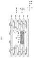
- FIG. 1 is a cross-sectional structure diagram of an electronic device 10 including a multilayer substrate 20 according to an embodiment of the present invention.
- FIG. 2A is a sectional view of the multilayer substrate 20.
- FIG. 2B is an exploded view of the multilayer substrate 20.
- FIG. 3A is a view of the electronic component 81 as viewed from above.
- FIG. 3B is a view of the electronic component 81 as viewed from the front side.
- FIG. 3C is a view of the package component 80 as viewed from above.
- FIG. 3D is a view of the package component 80 as viewed from the front side.
- FIG. 4A is a perspective view when the package component 80 is manufactured.
- FIG. 4B is a perspective view when the package component 80 is manufactured.
- FIG. 4A is a perspective view when the package component 80 is manufactured.
- FIG. 4B is a perspective view when the package component 80 is manufactured.
- FIG. 4C is a perspective view when the package component 80 is manufactured.
- FIG. 4D is a perspective view when the package component 80 is manufactured.
- FIG. 5A is a perspective view when the package component 80 is manufactured.
- FIG. 5B is a perspective view when the package component 80 is manufactured.
- FIG. 5C is a perspective view when the package component 80 is manufactured.
- FIG. 5D is a perspective view when the package component 80 is manufactured.
- FIG. 5E is a cross-sectional structure diagram when the multilayer substrate 20 is manufactured.
- FIG. 6A is a cross-sectional structure diagram when the multilayer substrate 20 is manufactured.
- FIG. 6B is a cross-sectional structure diagram when the multilayer substrate 20 is manufactured.
- FIG. 7 is a cross-sectional structure diagram when the multilayer substrate 20 is manufactured.
- FIG. 8 is a cross-sectional structure diagram of the multilayer substrate 20a.
- FIG. 9A is a perspective view at the time of manufacturing the package component 80 and the insulator sheet 23.
- FIG. 9B is a perspective view at the time of manufacturing the package component 80 and the insulator sheet 23.
- FIG. 9C is a perspective view at the time of manufacturing the package component 80 and the insulator sheet 23.
- FIG. 9D is a perspective view at the time of manufacturing the package component 80 and the insulator sheet 23.
- FIG. 10 is a cross-sectional structure diagram when the multilayer substrate 20a is manufactured.
- FIG. 11 is a cross-sectional structure diagram when the multilayer substrate 20a is manufactured.
- FIG. 12 is a cross-sectional structure diagram of the multilayer substrates 20b and 20g.
- FIG. 13 is a cross-sectional structure diagram when the multilayer substrates 20b and 20g are manufactured.
- FIG. 14 is a cross-sectional structure diagram when the multilayer substrates 20b and 20g are manufactured.
- FIG. 15 is a cross-sectional structure diagram of the multilayer substrates 20b and 20g during manufacturing.
- FIG. 16 is a cross-sectional structure diagram of the multilayer substrates 20b and 20g during manufacturing.
- FIG. 17 is a cross-sectional structure diagram of the multilayer substrate 20c.
- FIG. 18 is a cross-sectional structure diagram when the multilayer substrate 20c is manufactured.
- FIG. 19A is a cross-sectional structure diagram when the multilayer substrate 20c is manufactured.
- FIG. 19B is a cross-sectional structure diagram when the multilayer substrate 20c is manufactured.
- FIG. 20 is a cross-sectional structure diagram of the multilayer substrate 20d.
- FIG. 21 is a sectional view of the multilayer substrate 20e.
- FIG. 22 is a sectional view of the multilayer substrate 20f.
- FIG. 23 is an external perspective view of the package component 80 of the multilayer board 20g.
- FIG. 24A is a view of the package component 80 as viewed from above.
- FIG. 24B is a cross-sectional structure diagram along AA in FIG. 24A.
- 24C is a cross-sectional structure diagram taken along line BB in FIG. 24A.
- FIG. 25 is an external perspective view of the package component 80 whose upper and lower surfaces are constituted by the external electrodes 84 a and 84 b and the coating member 86.
- FIG. 26 is a cross-sectional structure diagram when the resin multilayer substrate 500 is manufactured.
- FIG. 1 is a cross-sectional structure diagram of an electronic device 10 including a multilayer substrate 20 according to an embodiment of the present invention.
- FIG. 2A is a sectional view of the multilayer substrate 20.
- FIG. 2B is an exploded view of the multilayer substrate 20.
- FIG. 3A is a view of the electronic component 81 as viewed from above.
- FIG. 3B is a view of the electronic component 81 as viewed from the front side.
- FIG. 3C is a view of the package component 80 as viewed from above.
- 3D is a view of the package component 80 as viewed from the front side.
- the via-hole conductors v100 and v102 are omitted.
- the stacking direction of the multilayer substrate 20 is defined as the vertical direction.
- 1, 2A, and 2B is defined as the front-rear direction (an example of the second orthogonal direction), and the left-right direction of the paper in FIGS. Example).
- the up-down direction, the left-right direction, and the front-rear direction are orthogonal to each other.
- the electronic device 10 is, for example, a mobile phone, a personal computer, a game machine, a wearable terminal, or the like.
- FIG. 1 only modules and mother boards provided in the electronic device 10 are illustrated, and the casing of the electronic device 10 and other configurations are omitted.
- the electronic device 10 includes a multilayer substrate 20, electronic components 60 and 70, and a mother substrate 100.
- the multilayer substrate 20 is a plate-shaped resin substrate having a rectangular shape when viewed from above.
- the long side extends in the left-right direction and the short side extends in the front-rear direction.
- the multilayer substrate 20 includes a base material 22, external electrodes 24a to 24d, 26a and 26b, circuit conductor layers 28a to 28e, 29a to 29e, via-hole conductors v1 to v7, v11 to v17, v100, and v102.
- the package part 80 is provided.
- the external electrodes are provided in addition to the external electrodes 24a to 24d, 26a, and 26b, but the external electrodes other than the external electrodes 24a to 24d, 26a, and 26b are omitted in FIGS.
- the circuit conductor layers are provided in addition to the circuit conductor layers 28a to 28e and 29a to 29e, but the circuit conductor layers other than the circuit conductor layers 28a to 28e and 29a to 29e are shown in FIGS. Omitted.
- via-hole conductors are provided in addition to the via-hole conductors v1 to v7 and v11 to v17, but the via-hole conductors other than the via-hole conductors v1 to v7 and v11 to v17 are omitted in FIGS. 1 and 2A.
- the base material 22 is a flexible plate-like member having a rectangular shape when viewed from above, as shown in FIG. 2A.
- the base material 22 is a laminate in which insulator sheets 22a to 22g (an example of a plurality of insulator layers) are laminated in this order from the upper side to the lower side.
- the base material 22 has two main surfaces.
- the upper main surface of the base material 22 is referred to as a front surface
- the lower main surface of the base material 22 is referred to as a back surface.
- the back surface of the base material 22 is a mounting surface that faces the mother substrate 100 when the multilayer substrate 20 is mounted.
- the insulator sheets 22a to 22g have a rectangular shape when viewed from above, and have the same shape as the base material 22.
- the insulator sheets 22a to 22g are made of a material including a flexible thermoplastic resin (an example of a first resin) such as polyimide or liquid crystal polymer.
- a flexible thermoplastic resin an example of a first resin
- the upper main surface of the insulator sheets 22a to 22g is referred to as a front surface
- the lower main surface of the insulator sheets 22a to 22g is referred to as a back surface.
- through holes H1 to H3 having a rectangular shape when viewed from above are provided at the centers (near the intersections of the diagonal lines) of the insulator sheets 22b to 22d, respectively.
- the through holes H1 to H3 are formed so as to connect the front and back surfaces of the insulator sheets 22b to 22d, respectively. Further, the outer edges of the through holes H1 to H3 overlap each other when viewed from above. Therefore, the through holes H1 to H3 are connected to one.
- the upper opening of the through hole H1 is closed by the insulator sheet 22a.
- the opening on the lower side of the through hole H3 is blocked by the insulator sheet 22e.
- a rectangular parallelepiped space Sp in which the through holes H1 to H3 are connected is formed in the base material 22.
- the package component 80 is built in the base material 22 and has a rectangular parallelepiped shape.
- a surface positioned on the upper side is referred to as an upper surface (an example of the first plane)
- a surface positioned on the lower side Is called the lower surface (an example of the second plane)
- the front surface is called the front surface
- the rear surface is called the rear surface
- the right surface is called the right surface
- the left surface is Called the left side.
- the upper surface, the lower surface, the front surface, the rear surface, the right surface, and the left surface are substantially flat.
- the upper surface and the lower surface are planes that are substantially perpendicular to the vertical direction.
- the front surface, the rear surface, the right surface, and the left surface are planes that are substantially perpendicular to the upper surface and the lower surface and substantially parallel to the vertical direction.
- the front surface, the rear surface, the right surface, and the left surface may be collectively referred to as a side surface.
- chamfering is not performed on the joint portions of the upper surface, the lower surface, the front surface, the rear surface, the right surface, and the left surface, but the joint portions may be chamfered. It should be noted that being substantially flat and being substantially parallel or vertical means that it is allowed to slightly deviate from the plane or slightly deviate from parallel or vertical due to manufacturing variations.
- the package component 80 is accommodated in the space Sp. Thereby, the package component 80 penetrates the insulator sheets 22b to 22d in the vertical direction. Furthermore, the back surface of the insulator sheet 22 a is in contact with the upper surface of the package component 80, and the surface of the insulator sheet 22 e (an example of the first insulator layer) is in contact with the lower surface of the package component 80. Further, the inner peripheral surfaces of the through holes H 1 to H 3 are in contact with the side surfaces of the package component 80. Further, the insulator sheets 22a to 22e are fixed to the package component 80. More specifically, as will be described later, the insulator sheets 22a to 22g are solidified after being softened in the thermocompression bonding process of the base material 22.
- the insulating sheets 22a to 22g are softened, the insulating sheets 22a to 22e are formed in the gaps between the inner peripheral surface of the space Sp and the upper, lower, and side surfaces (hereinafter also referred to as surfaces) of the package component 50.
- the gaps are filled, and the gaps are filled with the insulator sheets 22a to 22e.
- the insulator sheets 22a to 22e are solidified, the inner peripheral surface of the space Sp and the surface of the package component 50 are fixed and are not easily separated.
- the package component 80 includes an electronic component 81 (an example of a first electronic component) and a coating member 86, as shown in FIGS. 2A and 3A to 3D.
- the electronic component 81 is, for example, a chip-type electronic component such as a capacitor or an inductor, and includes a main body 82 (an example of a first main body) and external electrodes 84 and 84b.
- the main body 82 is a rectangular parallelepiped member made of a material such as ceramic, and includes circuit elements (not shown) such as capacitors and inductors therein.
- the external electrode 84 a (an example of the first external electrode) is provided on the surface of the main body 82, and is provided on either the upper surface or the lower surface of the main body 82.
- the external electrode 84a covers the entire left surface of the main body 82 (an example of a surface on one side in the first orthogonal direction) and is an area adjacent to the left surface, and has an upper surface (one side in the stacking direction).
- the external electrode 84 b is provided on either the upper surface or the lower surface of the main body 82.
- the external electrode 84b is provided on the surface of the main body 82.
- the external electrode 84b covers the entire right surface of the main body 82 and is adjacent to the right surface, and includes an upper surface, a lower surface, a front surface, and a front surface. It covers a part of the rear surface.
- the external electrodes 84a and 84b are formed, for example, by performing nickel plating and tin plating on a base electrode formed by applying a conductive paste mainly composed of silver or the like.
- the coating member 86 is made of a material containing a thermosetting resin (an example of a second resin) such as an epoxy resin, and covers at least a part of the surface of the electronic component 81. Thereby, at least a part of the upper surface of the package component 80 and at least a part of the lower surface of the package component 80 are constituted by the coating member 86. In the present embodiment, the coating member 86 covers the entire surface of the electronic component 81. Therefore, the electronic component 81 is not exposed from the coating member 86. The entire upper surface of the package component 80 and the entire lower surface of the package component 80 are constituted by a coating member 86.
- the lower surface of the coating member 86 (that is, the lower surface of the package component 80)
- through holes for via-hole conductors v100 and v102 described later are provided on the lower surface of the coating member 86 (that is, the lower surface of the package component 80). Therefore, the lower surface of the coating member 86 (that is, the lower surface of the package component 80) is recessed in the through hole. However, since the through hole is small, the lower surface of the coating member 86 (that is, the lower surface of the package component 80) is interpreted as a plane for convenience.
- the Young's modulus of a thermosetting resin such as an epoxy resin used for the coating member 86 at the softening point temperature of a thermoplastic resin such as polyimide or liquid crystal polymer used for the insulator sheets 22a to 22g is as follows. It is larger than the Young's modulus of thermoplastic resins such as polyimide and liquid crystal polymer used for 22g.
- the softening point is the temperature at which the temperature of the resin rises and begins to deform.
- the softening point of polyimide is 120 ° C., for example, and the softening point of liquid crystal polymer is 150 ° C., for example.
- the softening point means a value measured according to the method described in JIS K7206.
- the linear expansion coefficient of a thermosetting resin such as an epoxy resin used for the coating member 86 is equal to or higher than the linear expansion coefficient of the material (ceramic) of the main body 82, and polyimide or the like used for the insulator sheets 22a to 22g. It is below the linear expansion coefficient of thermoplastic resins, such as a liquid crystal polymer. More specifically, the linear expansion coefficient of the ceramic is, for example, about 7 ⁇ 10 ⁇ 6 / ° C., the linear expansion coefficient of the liquid crystal polymer is, for example, about 16 ⁇ 10 ⁇ 6 / ° C., and the linear expansion coefficient of the epoxy resin. Is, for example, about 10 ⁇ 10 ⁇ 6 / ° C. However, the linear expansion coefficient of the epoxy resin may be adjusted by the amount of filler added to the epoxy resin.
- the external electrodes 24a to 24d are rectangular conductor layers and are provided on the surface of the insulator sheet 22a.
- the external electrodes 24a to 24d are arranged in this order from the left side to the right side.
- the external electrodes 26a and 26b are rectangular conductor layers, and are provided on the back surface of the insulator sheet 22g.
- the external electrodes 26a and 26b are arranged in this order from the left side to the right side.
- the circuit conductor layers 28a to 28e and 29a to 29e are conductor layers provided on the surfaces of the insulator sheets 22b to 22f, respectively, and constitute a part of the circuit in the multilayer substrate 20.
- the circuit conductor layers 28a to 28e and 29a to 29e are linear wirings in FIG. 2, but may be capacitor conductors, ground conductors, or the like having a rectangular shape.
- the circuit conductor layers 28 a to 28 e extend in the left-right direction on the left side with respect to the package component 80. However, the right end of the circuit conductor layer 28e overlaps with the package component 80 when viewed from above.
- the circuit conductor layers 29 a to 29 e extend in the left-right direction on the right side with respect to the package component 80. However, the left end of the circuit conductor layer 29e overlaps with the package component 80 when viewed from above.
- the material of the circuit conductor layers 28a to 28e, 29a to 29e and the external electrodes 24a to 24d, 26a, and 26b as described above is, for example, a metal foil made of copper.
- the surface of the circuit conductor layers 28a to 28e, 29a to 29e and the external electrodes 24a to 24d, 26a and 26b is plated with zinc to reduce the surface roughness.
- the surface roughness of the main surfaces of the circuit conductor layers 28a to 28e, 29a to 29e and the external electrodes 24a to 24d, 26a, and 26b that are in contact with the insulator sheets 22a to 22g is the circuit conductor layers 28a to 28e, 29a.
- the surface roughness of the main surfaces not contacting the insulator sheets 22a to 22g is larger.
- the circuit conductor layers 28a to 28e, 29a to 29e, the external electrodes 24a to 24d, 26a and 26b, and the insulator sheets 22a to 22g are made of the circuit conductor layers 28a to 28e, 29a to 29e and external electrodes 24a to 24d, 26a and 26b are physically fixed by entering into the irregularities, and are not chemically bonded. For this reason, there is almost no foreign matter such as a resin serving as an adhesive component at the boundary between the circuit conductor layers 28a to 28e, 29a to 29e, the external electrodes 24a to 24d, 26a and 26b, and the insulator sheets 22a to 22g. .
- the via-hole conductors v1 to v7 are interlayer connection conductors that penetrate the insulating sheets 22a to 22g in the vertical direction, respectively.
- Each of the via-hole conductors v1 to v6 has a shape that becomes thicker from the upper side to the lower side.
- the via-hole conductor v7 has a shape that becomes thinner from the upper side to the lower side.
- the via-hole conductor v1 connects the external electrode 24a and the circuit conductor layer 28a.
- the via-hole conductor v2 connects the circuit conductor layer 28a and the circuit conductor layer 28b.
- the via-hole conductor v3 connects the circuit conductor layer 28b and the circuit conductor layer 28c.
- the via-hole conductor v4 connects the circuit conductor layer 28c and the circuit conductor layer 28d.
- the via-hole conductor v5 connects the circuit conductor layer 28d and the circuit conductor layer 28e.
- the via hole conductor v6 and the via hole conductor v7 are connected to each other to form a series of via hole conductors.
- the via-hole conductors v6 and v7 connect the circuit conductor layer 28e and the external electrode 26a. Thereby, the external electrode 24a and the external electrode 26a are electrically connected.
- Via-hole conductors v11 to v17 are interlayer connection conductors penetrating the insulating sheets 22a to 22g in the vertical direction, respectively.
- Each of the via-hole conductors v11 to v16 has a shape that becomes thicker from the upper side to the lower side.
- the via-hole conductor v17 has a shape that becomes thinner from the upper side to the lower side.
- the via-hole conductor v11 connects the external electrode 24b and the circuit conductor layer 29a.
- the via-hole conductor v12 connects the circuit conductor layer 29a and the circuit conductor layer 29b.
- the via-hole conductor v13 connects the circuit conductor layer 29b and the circuit conductor layer 29c.
- the via-hole conductor v14 connects the circuit conductor layer 29c and the circuit conductor layer 29d.
- the via-hole conductor v15 connects the circuit conductor layer 29d and the circuit conductor layer 29e.
- the via hole conductor v16 and the via hole conductor v17 constitute a series of via hole conductors by being connected to each other.
- the via-hole conductors v16 and v17 connect the circuit conductor layer 29e and the external electrode 26b. Thereby, the external electrode 24d and the external electrode 26b are electrically connected.
- the via-hole conductor v100 (an example of a connection conductor) penetrates the coating member 86 and the insulating sheet 22e in the vertical direction, and connects the external electrode 84a and the circuit conductor layer 28e. More specifically, the upper end of the via hole conductor v100 is connected to the external electrode 84a, and the lower end of the via hole conductor v100 is connected to the circuit conductor layer 28e.
- the via-hole conductor v100 penetrates the coating member 86 existing between the external electrode 84a and the lower surface of the package component 80 in the vertical direction and penetrates the insulator sheet 22e in the vertical direction. Therefore, the via-hole conductor v100 passes through the lower surface of the package component 80.
- the via-hole conductor v102 penetrates the coating member 86 and the insulating sheet 22e in the vertical direction, and connects the external electrode 84b and the circuit conductor layer 29e. More specifically, the upper end of the via hole conductor v102 is connected to the external electrode 84b, and the lower end of the via hole conductor v102 is connected to the circuit conductor layer 29e.
- the via-hole conductor v102 penetrates the coating member 86 existing between the external electrode 84b and the lower surface of the package component 80 in the vertical direction and penetrates the insulator sheet 22e in the vertical direction. Therefore, the via-hole conductor v102 passes through the lower surface of the package component 80.
- Via-hole conductors v1 to v7, v11 to v17, v100, and v102 are solidified conductive pastes mainly composed of metals such as copper, tin, and silver.
- the material of the via-hole conductors v1 to v7 and v11 to v17 and the material of the via-hole conductors v100 and v102 are the same.
- the electronic components 60 and 70 are electronic components mounted on the surface of the base material 22 and are, for example, semiconductor integrated circuits. However, the electronic components 60 and 70 may be chip-type electronic components such as capacitors and inductors.
- the electronic component 60 includes a main body 60a and external electrodes 62a and 62b.
- the main body 60a has a rectangular parallelepiped shape.
- the external electrodes 62a and 62b are provided on the lower surface of the main body 60a, and are arranged in this order from the left side to the right side.
- the external electrodes 62a and 62b are connected to the external electrodes 24a and 24b, for example, by solders 64a and 64b.
- the electronic component 70 includes a main body 70a and external electrodes 72a and 72b.
- the main body 70a has a rectangular parallelepiped shape.
- the external electrodes 72a and 72b are provided on the lower surface of the main body 70a, and are arranged in this order from the left side to the right side.
- the external electrodes 72a and 72b are connected to the external electrodes 24c and 24d by, for example, solders 74a and 74b.
- the mother board 100 is a large circuit board used for a mobile phone or the like.
- the mother substrate 100 is basically a hard substrate that does not have flexibility, but may have flexibility.
- the mother substrate 100 includes a main body 102 and external electrodes 104a and 104b.
- the main body 102 is a plate-shaped multilayer substrate having a rectangular shape when viewed from above.
- An electric circuit is formed inside and on the surface of the main body 102.
- the upper main surface of the main body 102 is referred to as a front surface
- the lower main surface of the main body 102 is referred to as a back surface.
- a surface mount type component, a shield case, or the like may be mounted on at least one of the front surface and the back surface of the mother substrate 100.
- the external electrodes 104 a and 104 b are rectangular conductor layers and are provided on the surface of the main body 102.
- the external electrodes 104a and 104b are arranged in this order from the left side to the right side.
- the mother substrate 100 may further be provided with external electrodes (not shown) other than the external electrodes 104a and 104b.
- the multilayer substrate 20 is mounted on the surface of the mother substrate 100. More specifically, the external electrodes 26a and 26b are mounted on the external electrodes 104a and 104b by solders 110a and 110b, respectively.
- FIGS. 5A to 5D are perspective views when the package component 80 is manufactured. 4A to 4D and 5A to 5D that the electronic component 81 is indicated by a dotted line means that the electronic component 81 is present in the resin. 5E, FIG. 6A, FIG. 6B, and FIG. 7 are cross-sectional structure diagrams when the multilayer substrate 20 is manufactured.
- a case where one multilayer substrate 20 is manufactured will be described as an example, but actually, a plurality of multilayer substrates 20 are manufactured simultaneously by laminating and cutting large-sized insulator sheets.
- the manufacturing method of the package component 80 will be described with reference to FIGS. 4A to 4D and FIGS. 5A to 5D.
- this step an example of the first step
- the package component 80 is formed by covering the entire surface of the electronic component 81 with the coating member 86.
- a plurality of electronic components 81 are arranged on a resin sheet 200 such as a PET film.
- a resin sheet 200 such as a PET film.
- the material containing the UV curable epoxy resin is irradiated with UV.
- the resin layer 202 is formed.
- the plurality of electronic components 81 are buried in the resin layer 202.
- the upper surface of the resin layer 202 is polished with a grinder to adjust the vertical thickness of the resin layer 202 to an appropriate value, and the upper surface of the resin layer 202 is flattened.
- the resin sheet 200 is peeled from the plurality of electronic components 81 and the resin layer 202. At this time, a part of the external electrodes 84 a and 84 b is exposed from the resin layer 202.
- the resin sheet 201 is attached to the lower surfaces of the plurality of electronic components 81 and the resin layer 202.
- a liquid material containing a UV curable epoxy resin is applied onto the resin layer 202, and then the material containing the UV curable epoxy resin is irradiated with UV.
- the resin layer 203 is formed. Thereby, the plurality of electronic components 81 are buried in the resin layers 202 and 203 and are not exposed to the outside.
- the resin layer 203 may be formed in advance, a plurality of electronic components 81 may be disposed on the resin layer 203, and the resin layer 202 may be formed on the resin layer 203.
- the upper surface of the resin layer 203 is polished by a grinder to adjust the vertical thickness of the resin layers 202 and 203 to an appropriate value, and the upper surface of the resin layer 203 is flattened.
- the resin layers 202 and 203 are cut with a dicer, and then the resin sheet 201 is peeled from the resin layer 203. Thereby, a plurality of package parts 80 are completed.
- insulator sheets 22a to 22g made of a liquid crystal polymer are prepared.
- a copper foil is formed on the entire main surface of one of the insulator sheets 22a to 22g. Specifically, copper foil is attached to the surfaces of the insulator sheets 22a to 22f. A copper foil is attached to the back surface of the insulator sheet 22g. Furthermore, the surface of the copper foils of the insulator sheets 22a to 22g is smoothed by, for example, applying zinc plating for rust prevention. In addition, metal foils other than copper foil may be used.
- through holes H1 to H3 are formed in the insulating sheets 22b to 22d.
- the through holes H1 to H3 are formed, for example, by irradiating a laser beam from the back surfaces of the insulator sheets 22b to 22d.
- the through holes H1 to H3 may be formed by punching the insulating sheets 22b to 22d by punching.
- the external electrodes 24a to 24d are formed on the surface of the insulator sheet 22a as shown in FIG. 2A.
- a resist having the same shape as the external electrodes 24a to 24d shown in FIG. 3 is printed on the copper foil on the surface of the insulating sheet 22a.
- the copper foil of the part which is not covered with the resist is removed by performing an etching process with respect to copper foil. Thereafter, the resist is removed by spraying a cleaning liquid (resist removing liquid).
- a cleaning liquid resist removing liquid
- circuit conductor layers 28a and 29a are formed on the surface of the insulator sheet 22b. Further, as shown in FIG. 2A, circuit conductor layers 28b and 29b are formed on the surface of the insulator sheet 22c. Further, as shown in FIG. 2A, circuit conductor layers 28c and 29c are formed on the surface of the insulator sheet 22d. Further, as shown in FIG. 2A, circuit conductor layers 28d and 29d are formed on the surface of the insulator sheet 22e. Further, as shown in FIG. 2A, circuit conductor layers 28e and 29e are formed on the surface of the insulator sheet 22f. As shown in FIG.
- the external electrodes 26a and 26b are formed on the back surface of the insulating sheet 22g.
- the process of forming the circuit conductor layers 28a to 28e, 29a to 29e and the external electrodes 26a and 26b is the same as the process of forming the external electrodes 24a and 24b, and the description thereof will be omitted.
- the step of forming the through holes H1 to H3 may be performed after the step of forming the external electrodes 24a, 24b, 26a, 26b and the circuit conductor layers 28a to 28e, 29a to 29e.
- a through hole is formed by irradiating a laser beam at a position where the via-hole conductors v1 to v4, v6, v7, v11 to v14, v16, and v17 are formed. Then, the through hole is filled with a conductive paste whose main component is a metal such as copper, tin or silver.
- an insulator sheet 22e (an example of a first insulator layer) that contacts the lower surface of the package component 80, and an upper side (an example of one side in the stacking direction) of the insulator sheet 22e.
- the insulating sheets 22a to 22e are stacked so as to incorporate the package component 80 in the insulating sheets 22a to 22d (an example of the third insulating layer) stacked on (4). That is, after the insulating sheets 22a to 22d are stacked, the package component 80 is inserted into the through holes H1 to H3 from the lower side, and the insulating sheet 22e is stacked on the lower side of the insulating sheet 22d.
- the insulator sheets 22a to 22e are subjected to heat treatment and pressure treatment (thermocompression treatment), and the insulator sheets 22a to 22e are thermocompression bonded (hereinafter, this process is also referred to as a primary press).
- the heat treatment is performed at a temperature not lower than the softening point of the thermoplastic resin constituting the insulating sheets 22a to 22g and at which the thermosetting resin constituting the coating member 86 is not decomposed (for example, 260 ° C. to 290 ° C.).
- this heat treatment temperature it is sufficient that the thermosetting resin constituting the coating member 86 does not soften more greatly than the thermoplastic resin constituting the insulator sheets 22a to 22g.
- Softening means that Young's modulus becomes small.
- the Young's modulus of the resin that constitutes the coating member 86 only needs to be larger than the Young's modulus of the resin that constitutes the insulator sheets 22a to 22g under the same heat treatment temperature condition.
- the insulator sheets 22a to 22e are softened and the conductive paste in the through holes is solidified.
- the insulator sheets 22a to 22e are joined together, and the via-hole conductors v1 to v4 and v11 to v14 are formed.
- thermoplastic resin of the insulator sheets 22a to 22e is softened by thermocompression, so that the thermoplastic resin flows into the gap formed between the inner peripheral surface of the space Sp and the surface of the package component 80. Thereafter, the insulator sheets 22a to 22e are cooled to solidify the thermoplastic resin, and the inner peripheral surface of the space Sp and the surface of the package component 80 are fixed.
- a through hole is formed by irradiating a laser beam at a position where the via-hole conductors v5, v15, v100, and v102 are formed.
- the through hole is provided so as to penetrate a part of the insulating sheet 22e and the coating member 86 and to expose a part of the external electrodes 84a and 84b of the package component 80.
- the through hole is filled with a conductive paste mainly composed of a metal such as copper, tin, or silver.
- insulator sheets 22f and 22g (an example of a fourth insulator layer) stacked on the lower side (an example of the other side in the stacking direction) of the insulator sheet 22e are insulators.
- Laminate below the sheet 22e (an example of the second step and the sixth step).
- the conductive paste (an example of a connection conductor) to be the via-hole conductors v100 and v102 and the circuit conductor layers 28e and 29e are connected.
- the insulating sheets 22a to 22g are subjected to heat treatment and pressure treatment (thermocompression treatment), and the insulating sheets 22a to 22g are thermocompression bonded to form the base material 22 (hereinafter, this process is referred to as 2). Also called the next press, an example of the third step). At this time, heat treatment is performed at a temperature (for example, 260 ° C. to 290 ° C.) that is equal to or higher than the softening point of the thermoplastic resin that forms the insulating sheets 22a to 22g and that does not decompose the thermosetting resin that forms the coating member 86. I do. In the secondary press, the insulator sheets 22a to 22g are softened and the conductive paste in the through holes is solidified.
- a temperature for example, 260 ° C. to 290 ° C.
- the insulator sheets 22a to 22g are joined together, and the via-hole conductors v5 to v7, v15 to v17, v100, and v102 are formed (an example of the fifth step).
- the via hole conductor v100 connects the external electrode 84a and the circuit conductor layer 28e, and the via hole conductor v102 connects the external electrode 84b and the circuit conductor layer 29e.
- the multilayer substrate 20 is completed through the above steps.
- the electronic components 60 and 70 are soldered to the base material 22 with solder 64a, 64b, 74a. It is mounted by 74b.
- the multilayer substrate 20 is mounted on the mother substrate 100 with solders 110a and 110b. After that, the electronic device 10 is completed by mounting the mother substrate 100 on the housing.
- the flatness of the upper surface and the lower surface of the base material 22 can be improved. More specifically, in the resin multilayer substrate 500 described in Patent Document 1, external electrodes (not shown) are provided on the upper and lower surfaces of the components 503a and 503b. Therefore, there are irregularities on the upper and lower surfaces of the components 503a and 503b. When such irregularities exist, large gaps are formed between the upper and lower surfaces of the components 503a and 503b and the resin sheets 502a and 502d. In the thermocompression bonding process, the resin sheets 502a and 502d in the vicinity of the components 503a and 503b soften and flow and flow into the gap. As a result, irregularities are formed on the upper and lower surfaces of the resin multilayer substrate 500 directly above and below the components 503a and 503b and in the vicinity thereof.
- the coating member 86 is made of a material including a thermosetting resin and covers at least a part of the surface of the electronic component 81.
- a part of the upper and lower surfaces of the package component 80 is constituted by a coating member 86. That is, the unevenness of the upper surface and the lower surface of the electronic component 81 is flattened by the coating member 86.
- the Young's modulus of the thermosetting resin constituting the coating member 86 at the softening point temperature of the thermoplastic resin constituting the insulator sheets 22a to 22g constitutes the insulator sheets 22a to 22g. It is larger than the Young's modulus of the thermoplastic resin.
- the coating member 86 is not softened or hardly softened, and the insulator sheets 22a to 22g are softened.
- the insulating sheets 22a to 22g soften and flow while the upper and lower surfaces of the package component 80 are maintained flat, and a gap between the surface of the package component 80 and the inner peripheral surface of the space Sp is formed. fill in.
- the insulator sheets 22a and 22e in the vicinity of the package component 80 are suppressed from being softened and flowed and flowing into the gap in a large amount.
- the front and back surfaces of the multilayer substrate 20 it is possible to suppress the formation of irregularities directly above and below the package component 80 and in the vicinity thereof.
- the occurrence of disconnection between the electronic component 81 and the circuit conductor layers 28e and 29e is suppressed. More specifically, since the upper surface and the lower surface of the package component 80 are flat, the gap between the upper surface of the package component 80 and the back surface of the insulator sheet 22a, and the lower surface of the package component 80 and the surface of the insulator sheet 22a. The gap between is very small. Therefore, in the process of FIG. 5E, for example, the package component 80 is prevented from rotating around an axis extending in the front-rear direction (clockwise or counterclockwise in FIG. 5E). Thereby, in the process shown in FIG.
- the back surface of the insulator sheet 22e immediately below the package component 80 is suppressed from being inclined. Accordingly, the vertical positions of the lower end of the via-hole conductor v100 and the lower end of the via-hole conductor v102 are aligned. As a result, in the step shown in FIG. 7, the via-hole conductor v100 and the circuit conductor layer 28e are more reliably connected, and the via-hole conductor v102 and the circuit conductor layer 29e are more reliably connected.
- the side surface of the package component 80 is a plane parallel to the vertical direction.
- the gap between the side surface of the package component 80 and the inner peripheral surfaces of the through holes H1 to H3 is very small. This suppresses a large amount of the insulator sheets 22b to 22e from flowing into the gap during the heat treatment and pressure treatment of the base material 22. As a result, the package component 80 is prevented from rotating around the axis extending in the vertical direction in the space Sp.
- the gap between the inner peripheral surface of the space Sp and the package component 80 can be reduced when the multilayer substrate 20 is manufactured.
- the package component 80 is configured by covering an electronic component 81 with a coating member 86. Therefore, the coating member 86 can be processed into an arbitrary shape and size by processing the coating member 86 by polishing or the like. As a result, the shape of the coating member 86 and the shape of the space Sp can be made closer, and the gap between the inner peripheral surface of the space Sp and the package component 80 can be reduced.
- the gap between the inner peripheral surface of the space Sp and the package component 80 is reduced, the flatness of the upper surface and the lower surface of the base material 22 is improved and the rotation of the package component 80 in the space Sp is suppressed. Is done. Therefore, the occurrence of mounting mistakes in the electronic components 60 and 70 and the multilayer substrate 20 is suppressed, and the occurrence of disconnection between the electronic component 81 and the circuit conductor layers 28e and 29e is suppressed.
- the material of the via-hole conductors v100 and v102 is the same as the material of the via-hole conductors v1 to v7 and v11 to v17. Therefore, the via-hole conductors v6, v7, v16, v17, v100, and v102 can be simultaneously cured during the heat treatment and pressure treatment of the base material 22.
- the multilayer substrate 20 it is possible to suppress the occurrence of peeling between the main body 82 and the coating member 86 and the peeling between the coating member 86 and the insulating sheets 22a to 22e. More specifically, heat treatment is performed when the multilayer substrate 20 is manufactured. Since the main body 82, the coating member 86, and the insulator sheets 22a to 22e are made of different materials, their expansion amounts are also different. Such a difference in the expansion amount causes peeling between the main body 82 and the coating member 86 and peeling between the coating member 86 and the insulating sheets 22a to 22e.
- the linear expansion coefficient of a thermoplastic resin such as an epoxy resin used for the coating member 86 is equal to or greater than the linear expansion coefficient of the material (ceramic) of the main body 82, and the insulator sheets 22a to 22g It is below the linear expansion coefficient of thermoplastic resins, such as a polyimide used and liquid crystal polymer.
- thermoplastic resin The difference between the linear expansion coefficient of the thermoplastic resin and the linear expansion coefficient of the thermoplastic resin such as polyimide or liquid crystal polymer used for the insulator sheets 22a to 22g can be reduced. As a result, the difference in the expansion amount is reduced, and the occurrence of the peeling is suppressed.
- FIG. 8 is a cross-sectional structure diagram of the multilayer substrate 20a.
- the multilayer substrate 20 a is different from the multilayer substrate 20 in the structure of the package component 80. More specifically, in the multilayer substrate 20a, the external electrodes 84a and 84b are exposed on the lower surface of the package component 80. Instead, the lower surface of the package component 80 is covered with the insulator sheet 23 (an example of a second insulator layer). Hereinafter, the multilayer substrate 20a will be described focusing on the difference.
- the lower surface of the package component 80 is a flat surface. However, a part of the lower surface of the package component 80 is configured by the coating member 86, and the remaining portion of the lower surface of the package component 80 is configured by the external electrodes 84a and 84b. Furthermore, the insulator sheet 23 has the same shape and the same size as the lower surface of the package component 80 when viewed from above, and covers the entire lower surface of the package component 80. Further, the sum of the vertical thickness of the package component 80 and the vertical thickness of the insulating sheet 23 is substantially equal to the total vertical thickness of the insulating sheets 22b to 22d.
- the via-hole conductor v100 penetrates the insulator sheets 23 and 22e in the vertical direction, and connects the external electrode 84a and the circuit conductor layer 28e. However, the via-hole conductor v100 does not penetrate the coating member 86.
- the via-hole conductor v102 penetrates the insulator sheets 23 and 22e in the vertical direction, and connects the external electrode 84b and the circuit conductor layer 29e. However, the via-hole conductor v102 does not penetrate the coating member 86.
- 9A to 9D are perspective views at the time of manufacturing the package component 80 and the insulator sheet 23.
- 9A to 9D that the electronic component 81 is indicated by a dotted line means that the electronic component 81 is present in the resin.
- 10 and 11 are cross-sectional structure diagrams when the multilayer substrate 20a is manufactured.
- the mother sheet 223 is made of a material containing a flexible thermoplastic resin such as polyimide or liquid crystal polymer, and is a large sheet in which the insulator sheets 23 are arranged in a matrix when viewed from above. is there.
- the material of the mother sheet 223 is the same as the material of the insulator sheets 22a to 22g.
- the material containing the UV curable epoxy resin is irradiated with UV, and the resin Layer 202 is formed. Accordingly, the plurality of electronic components 81 are buried in the resin layer 202 so that at least a part of the lower surfaces of the external electrodes 84 a and 84 b of the plurality of electronic components 81 are in contact with the mother sheet 223.
- the upper surface of the resin layer 202 is polished with a grinder to adjust the vertical thickness of the resin layer 202 to an appropriate value, and the upper surface of the resin layer 202 is flattened.
- the resin layer 202 is cut with a dicer. Thereby, a plurality of package components 80 having the insulator sheet 23 attached to the lower surface are completed.
- the conductive material is conducted to the through holes formed at positions where the via-hole conductors v1 to v4, v6, v7, v11 to v14, v16, and v17 are formed.
- the steps up to the step of filling the conductive paste are the same as those steps in the method for manufacturing the multilayer substrate 20, and thus the description thereof is omitted.
- the through hole is provided so as to penetrate part of the insulator sheet 22e and the insulator sheet 23 and to expose part of the external electrodes 84a and 84b of the package component 80.
- the package component 80 to which the insulator sheet 23 is attached is inserted into the through holes H1 to H3 from below, and the insulator sheets 22e is laminated below the insulator sheet 22d. Further, heat treatment and pressure treatment (also referred to as thermocompression treatment) are performed on the insulator sheets 22a to 22e (hereinafter, this step is also referred to as a primary press).
- a through-hole is formed by irradiating a laser beam at a position where the via-hole conductors v5, v15, v100, and v102 are formed. These through holes are filled with a conductive paste whose main component is a metal such as copper, tin or silver. Note that the subsequent steps of the method for manufacturing the multilayer substrate 20a are the same as the method for manufacturing the multilayer substrate 20, and thus the description thereof is omitted.
- the multilayer substrate 20 a configured as described above can also exhibit the same operational effects as the multilayer substrate 20.
- the package component 80 can be easily created. More specifically, in the method for manufacturing the multilayer substrate 20, the resin sheet 200 is peeled from the plurality of electronic components 81 and the resin layer 202 in the step illustrated in FIG. 4D. Further, in the step of FIG. 5A, after the front and back of the plurality of electronic components 81 and the resin layer 202 are reversed, the resin sheet 201 is attached to the lower surfaces of the plurality of electronic components 81 and the resin layer 202. As described above, in the method for manufacturing the multilayer substrate 20, it is necessary to peel the resin sheet 200 and attach the resin sheet 201 in order to cover the entire electronic component 81 with the coating member 86.
- a mother sheet 223 is used instead of the resin sheets 200 and 201.
- the material of the mother sheet 223 is the same material as the insulator sheets 22a to 22g. Therefore, the insulator sheet 23 obtained by dividing the mother sheet 223 is used as a part of the base material 22 without being peeled off from the lower surface of the package component 80. Therefore, in the manufacturing method of the multilayer substrate 20a, processes such as peeling and reversal are unnecessary, and the package component 80 can be easily created.
- FIG. 12 is a cross-sectional structure diagram of the multilayer substrates 20b and 20g.
- the multilayer substrate 20b is different from the multilayer substrate 20 in that the via-hole conductors v100 and v102 are further provided with circuit conductor layers 28f and 29f and via-hole conductors v8 and v18.
- the multilayer substrate 20b will be described focusing on the differences related to the following.
- the circuit conductor layers 28f and 29f are provided on the surface of the insulator sheet 22e.
- the circuit conductor layer 28f is provided on the right side of the circuit conductor layer 28d and extends in the left-right direction.
- the circuit conductor layer 29f is provided on the left side of the circuit conductor layer 29d and extends in the left-right direction.
- the circuit conductor layers 28 f and 29 f are in contact with the lower surface of the package component 80.
- the via-hole conductor v8 penetrates the insulator sheet 22e in the vertical direction, and connects the circuit conductor layer 28f and the circuit conductor layer 28e.
- the via-hole conductor v18 penetrates the insulator sheet 22e in the vertical direction, and connects the circuit conductor layer 29f and the circuit conductor layer 29e.
- the via-hole conductor v100 penetrates the coating member 86 in the vertical direction, and connects the external electrode 84a and the circuit conductor layer 28f. More specifically, the upper end of the via hole conductor v100 is connected to the external electrode 84a, and the lower end of the via hole conductor v100 is connected to the circuit conductor layer 28f.
- the via-hole conductor v100 penetrates the coating member 86 existing between the external electrode 84a and the lower surface of the package component 80 in the vertical direction, and does not penetrate the insulator sheet 22e in the vertical direction.
- the via-hole conductor v102 penetrates the coating member 86 in the vertical direction, and connects the external electrode 84b and the circuit conductor layer 29f. More specifically, the upper end of the via hole conductor v102 is connected to the external electrode 84b, and the lower end of the via hole conductor v102 is connected to the circuit conductor layer 29f.
- the via-hole conductor v102 penetrates the coating member 86 existing between the external electrode 84b and the lower surface of the package component 80 in the vertical direction, and does not penetrate the insulator sheet 22e in the vertical direction.
- 13 to 16 are cross-sectional structure diagrams of the multilayer substrates 20b and 20g when they are manufactured.
- the manufacturing method of the package component 80 of the multilayer substrate 20b is the same as the manufacturing method of the package component 80 of the multilayer substrate 20, description thereof will be omitted.
- the conductive material is conducted to the through holes formed at positions where the via-hole conductors v1 to v3, v5 to v7, v11 to v13, and v15 to v17 are formed.
- the steps up to the step of filling the conductive paste are the same as those steps in the method for manufacturing the multilayer substrate 20, and thus the description thereof is omitted.
- the conductive paste is filled in the through holes formed at positions where the via-hole conductors v4 and v14 are formed, whereas in the manufacturing method of the multilayer substrate 20b, the via-hole conductors v5 and v15 are formed.
- the conductive paste is filled in the through-hole formed at the position where it is formed.
- the package component 80 is inserted into the through holes H1 to H3 from below. Furthermore, the insulating sheets 22a to 22d are subjected to heat treatment and pressure treatment (primary press).
- a through-hole is formed by irradiating a laser beam at a position where the via-hole conductors v4, v14, v100, and v102 are formed. And as shown in FIG. 15, these through-holes are filled with the electrically conductive paste which has metals, such as copper, tin, and silver, as a main component.
- the package component 80 is built in the insulator sheets 22a to 22g, and the conductive paste (an example of the connection conductor) to be the via-hole conductors v100 and v102 is provided in the circuit conductor layers 28f and 29f, respectively.
- Insulator sheets 22e to 22g are laminated below the insulator sheet 22d so as to be connected to the substrate (an example of an eighth step). Further, the insulating sheets 22a to 22g are subjected to heat treatment and pressure treatment, and the insulating sheets 22a to 22g are thermocompression bonded (secondary press). In the secondary press, the insulator sheets 22a to 22g are softened and the conductive paste in the through holes is solidified.
- the insulator sheets 22a to 22g are joined together, and the via-hole conductors v4 to v8, v14 to v18, v100, and v102 are formed (an example of the seventh step).
- the multilayer substrate 20b is completed.
- the multilayer substrate 20b configured as described above can also exhibit the same effects as the multilayer substrate 20.
- the connection by the via-hole conductors v100 and v102 is stabilized.
- the via-hole conductors v100 and v102 penetrate the coating member 86 in the vertical direction and do not penetrate the insulator sheet 22e in the vertical direction. That is, the via-hole conductors v100 and v102 connect the external electrodes 84a and 84b and the circuit conductor layers 28f and 29f only through the coating member 86. Thereby, it is not necessary to consider the difference between the deformation amount of the insulator sheet 22e and the deformation amount of the coating member 86 in the heat treatment and the pressure treatment as compared with the multilayer substrate 20. Therefore, the connection by the via-hole conductors v100 and v102 is stabilized.
- FIG. 17 is a cross-sectional structure diagram of the multilayer substrate 20c.
- through-hole conductors v5 ′, v15 ′, v100 ′, and v102 ′ are used instead of the via-hole conductors v5, v15, v100, and v102, and the front and back of the insulator sheet 22f are reversed. And the via hole conductors v9 and v19 are different from the multilayer substrate 20.
- the multilayer substrate 20c will be described focusing on the difference.
- the via-hole conductors v5, v15, v100, and v102 were formed by filling the through holes formed in the insulator sheet 22e and the coating member 86 with a conductive paste and heating the conductive paste.
- the through-hole conductors v ⁇ b> 5 ′, v ⁇ b> 15 ′, v ⁇ b> 100 ′, and v ⁇ b> 102 ′ are formed by performing copper plating on the inner peripheral surfaces of the through holes formed in the insulator sheet 22 e and the coating member 86.
- the via-hole conductors v9 and v19 penetrate the insulator sheet 22f in the vertical direction and are connected to the circuit conductor layers 28e and 29e.
- the front and back of the insulator sheet 22f are reversed.
- the through-hole conductors v5 ', v15', v100 ', and v102' are connected to the via-hole conductors v6, v16, v9, and v19, respectively.
- the external electrode 84a and the circuit conductor layer 28e are connected via the through-hole conductor v100 'and the via-hole conductor v9.
- the external electrode 84b and the circuit conductor layer 29e are connected through a through-hole conductor v102 'and a via-hole conductor v19.
- FIGS. 18, 19A, and 19B are cross-sectional structural diagrams of the multilayer substrate 20c when it is manufactured.
- the manufacturing method of the package component 80 of the multilayer substrate 20c is the same as the manufacturing method of the package component 80 of the multilayer substrate 20, description thereof will be omitted.
- the steps from the step of preparing the insulator sheets 22a to 22g to the step of applying heat treatment and pressure treatment (primary press) to the insulator sheets 22a to 22e are as follows: Since these steps are the same as those in the method of manufacturing the multilayer substrate 20, the description thereof is omitted.
- a through hole is formed by irradiating a laser beam at a position where through-hole conductors v5 ', v15', v100 ', and v102' are formed. Then, as shown in FIG. 19A, these through holes are plated with copper to form through-hole conductors v5 ', v15', v100 ', and v102'.
- insulator sheets 22f and 22g are laminated under the insulator sheet 22e.
- the insulator sheet 22f is arranged so that the main surface on which the circuit conductor layers 28e and 29e are provided faces downward.
- the insulating sheets 22a to 22g are subjected to a heat treatment and a pressure treatment.
- the multilayer substrate 20c is completed through the above steps.
- the multilayer substrate 20c configured as described above can also exhibit the same effects as the multilayer substrate 20.
- FIG. 20 is a cross-sectional structure diagram of the multilayer substrate 20d.
- the multilayer substrate 20d is different from the multilayer substrate 20 in that it further includes a package component 80 '. Thus, two or more package parts may be incorporated in the multilayer substrate 20d.
- the package component 80 ′ includes an electronic component 81 ′ (an example of a first electronic component) and 81 ′′ (an example of a second electronic component).
- the electronic components 81 ′ and 81 ′′ are arranged side by side in the package component 80 ′.
- the package component 80 ′ may include a plurality of electronic components.
- the external electrodes 84a 'and 84b' of the electronic component 81 ' are provided only on the lower surface of the main body 82'.
- the external electrodes 84 a ′′ and 84 b ′′ of the electronic component 81 ′′ ′ are provided only on the lower surface of the main body 82 ′′.
- the external electrode may be provided only on the lower surface of the main body.
- FIG. 21 is a sectional view of the multilayer substrate 20e.
- the multilayer substrate 20e is different from the multilayer substrate 20 in that an insulator sheet 22h is laminated on the insulator sheet 22a and further provided with via-hole conductors v110 and v112.
- the multilayer substrate 20e will be described with reference to the drawings with a focus on the following differences.
- the base material 22 is configured by laminating insulator sheets 22h and 22a to 22g in this order from the upper side to the lower side.
- the external electrodes 24a to 24d are provided on the surface of the insulator sheet 22h.
- the circuit conductor layers 28g and 29g are provided on the surface of the insulator sheet 22a.
- the via-hole conductor v0 penetrates the insulator sheet 22h in the vertical direction, and connects the external electrode 24a and the circuit conductor layer 28h.
- the via-hole conductor v10 penetrates the insulator sheet 22h in the vertical direction, and connects the external electrode 24d and the circuit conductor layer 29g.
- the via-hole conductor v110 penetrates the coating member 86 and the insulating sheet 22a in the vertical direction, and connects the external electrode 84a and the circuit conductor layer 28g. More specifically, the upper end of the via hole conductor v110 is connected to the circuit conductor layer 28g, and the lower end of the via hole conductor v110 is connected to the external electrode 84a.
- the via-hole conductor v110 penetrates the coating member 86 existing between the external electrode 84a and the upper surface of the package component 80 in the vertical direction and penetrates the insulator sheet 22a in the vertical direction. Therefore, the via-hole conductor v110 passes through the upper surface of the package component 80.
- the via-hole conductor v112 penetrates the coating member 86 and the insulating sheet 22a in the vertical direction, and connects the external electrode 84b and the circuit conductor layer 29g. More specifically, the upper end of the via hole conductor v112 is connected to the circuit conductor layer 29g, and the lower end of the via hole conductor v112 is connected to the external electrode 84b.
- the via-hole conductor v112 penetrates the coating member 86 existing between the external electrode 84b and the upper surface of the package component 80 in the vertical direction and penetrates the insulator sheet 22a in the vertical direction. Therefore, the via-hole conductor v112 passes through the upper surface of the package component 80.
- the multilayer substrate 20e configured as described above can also exhibit the same effects as the multilayer substrate 20.
- the upper surface of the package component 80 is fixed by the via-hole conductors v110 and v112, and the lower surface of the package component 80 is fixed by the via-hole conductors v100 and v102.
- the package component 80 is more effectively suppressed from being displaced in the base material 22 due to an external force during use.
- disconnection between the package component 80 and the circuit conductor layers 28g, 29g, 28f, 29f is suppressed.
- FIG. 22 is a sectional view of the multilayer substrate 20f.
- the multilayer substrate 20f is different from the multilayer substrate 20e in that the package component 80 further includes an electronic component 81 '(an example of a second electronic component).
- the multilayer substrate 20f will be described with reference to the drawings with a focus on the following differences.
- the electronic component 81 (an example of the first electronic component) and the electronic component 81 ′ are arranged so as to overlap when viewed from above.
- the coating member 86 includes electronic parts 81 and 81 '. Note that the coating member 86 does not necessarily contain the electronic components 81 and 81 ′, and may cover at least a part of the surface of the electronic components 81 and 81 ′.
- the electronic component 81 ′ includes a main body 82 ′ and external electrodes 84 a ′ and 84 b ′.
- the main body 82 ′ has a rectangular parallelepiped shape and is located on the upper side with respect to the main body 82.
- the external electrodes 84a 'and 84b' are provided on the upper surface of the main body 82 ', and are arranged in this order from the left side to the right side.
- the via-hole conductor v110 penetrates the coating member 86 and the insulating sheet 22a in the vertical direction, and connects the external electrode 84a 'and the circuit conductor layer 28g.
- the via-hole conductor v112 passes through the coating member 86 and the insulating sheet 22a in the vertical direction, and connects the external electrode 84b 'and the circuit conductor layer 29g.
- the multilayer substrate 20 f configured as described above can also exhibit the same effects as the multilayer substrate 20.
- the package component 80 is prevented from rotating in the space Sp during the heat treatment and the pressure treatment. That is, since the positioning of the package component 80 on the base material 22 is performed with high accuracy, the positioning of the two electronic components 81 and 81 ′ is performed with high accuracy.
- FIG. 23 is an external perspective view of the package component 80 of the multilayer board 20g.
- FIG. 24A is a view of the package component 80 as viewed from above.
- FIG. 24B is a cross-sectional structure diagram along AA in FIG. 24A.
- 24C is a cross-sectional structure diagram taken along line BB in FIG. 24A.
- the multilayer substrate 20g is different from the multilayer substrate 20b in that through-hole conductors v120 and v122 are provided in the package component 80. Since the cross-sectional structure diagram of the multilayer substrate 20g is substantially the same as the cross-sectional structure diagram of the multilayer substrate 20b, FIG. 12 is used. Hereinafter, the multilayer substrate 20g will be described focusing on the difference.
- the through-hole conductor v120 penetrates the coating member 86 in the vertical direction, and connects the external electrode 84a and the circuit conductor layer 28f. More specifically, the upper end of the through-hole conductor v120 is connected to the external electrode 84a, and the lower end of the through-hole conductor v120 is connected to the circuit conductor layer 28f.
- the through-hole conductor v120 penetrates the coating member 86 existing between the external electrode 84a and the lower surface of the package component 80 in the vertical direction and does not penetrate the insulator sheet 22e in the vertical direction.
- the through-hole conductor v122 penetrates the coating member 86 in the vertical direction, and connects the external electrode 84b and the circuit conductor layer 29f. More specifically, the upper end of the through-hole conductor v122 is connected to the external electrode 84b, and the lower end of the through-hole conductor v122 is connected to the circuit conductor layer 29f.
- the through-hole conductor v122 penetrates the coating member 86 existing between the external electrode 84b and the lower surface of the package component 80 in the vertical direction and does not penetrate the insulator sheet 22e in the vertical direction.
- the through-hole conductors v120 and v122 as described above are formed by performing copper plating on the inner peripheral surface of the through hole provided in the coating member 86.
- the through-hole conductors v120 and v122 are formed before the package component 80 is accommodated in the space Sp. That is, after the package component 80 is completed, a through hole is formed in the coating member 86 by a laser beam. And copper plating is given to the internal peripheral surface of a through-hole. Thereby, since the conductor which does not protrude from a through-hole can be formed, the unevenness
- the multilayer substrate and the method of manufacturing the multilayer substrate according to the present invention are not limited to the method of manufacturing the multilayer substrates 20, 20a to 20g and the multilayer substrates 20, 20a to 20g, and can be changed within the scope of the gist.
- the side surface of the package component 80 may not be parallel to the stacking direction.
- a square frustum is cited.
- the side surface of the package component 80 may not be a flat surface.
- An example of the shape of the package component 80 whose side surface is not flat is a cylinder.
- FIG. 25 is an external perspective view of the package component 80 whose upper and lower surfaces are constituted by the external electrodes 84 a and 84 b and the coating member 86. As shown in FIG. 25, the external electrodes 84 a and 84 b may be exposed from the coating member 86 by increasing the polishing amount of the resin layers 202 and 203 at the time of manufacturing the package component 80.
- the external electrodes 84a and 84b and the via-hole conductors v100 and v102 can be connected or the external electrodes 84a and 84b and the circuit conductor layers 28f and 29f can be connected without forming a through hole in the coating member 86. .
- the multilayer substrates 20 and 20a to 20g may be used without being mounted on the mother substrate 100.
- the via-hole conductors v100 and v102 do not have to be provided.
- the insulator sheet 22a is in contact with the upper surface (an example of the second plane) of the package component 80.
- the via-hole conductors v110 and v112 (an example of a connection conductor) pass through the upper surface of the package component 80 and penetrate the coating member 86 and the insulator sheet 22a.
- the insulator sheet 23 may be in contact with the upper surface (an example of the second plane) instead of the lower surface of the package component 80.
- the insulator sheet 22h is further laminated on the insulator sheet 22a.
- the insulator sheet 22a is in contact with the upper surface (an example of the second plane) of the package component 80.
- circuit conductor layers 28g and 29g are provided on the surface of the insulator sheet 22a.
- the multilayer substrate 20a includes via-hole conductors v110 and v112 instead of the via-hole conductors v100 and v102.
- Via-hole conductors v110 and v112 (an example of a connection conductor) pass through the upper surface of the package component 80 and penetrate the coating member 86 and the insulator sheet 22a.
- the via-hole conductor v110 connects the circuit conductor layer 28g and the external electrode 84a
- the via-hole conductor v112 connects the circuit conductor layer 29g and the external electrode 84b.
- the via-hole conductors v110, v112 are provided instead of the via-hole conductors v100, v102, similarly to the multilayer substrates 20a, 20e. Also good.
- the insulator sheet 22a is in contact with the upper surface (an example of the second plane) of the package component 80.
- the via-hole conductors v110 and v112 pass through the upper surface of the package component 80 and penetrate the coating member 86 and the insulator sheet 22a.
- the via-hole conductors v110 and v112 are directly connected to the circuit conductor layers 28e and 29e, respectively.
- the circuit conductor layers 28e and 29e are connected via via-hole conductors different from the via-hole conductors v110 and v112. It may be connected directly to. That is, the via-hole conductors v110 and v112 only have to electrically connect the external electrodes 84a and 84b and the circuit conductor layers 28e and 29e, respectively.
- the present invention is useful for a multilayer substrate and a method for producing the multilayer substrate, and is particularly excellent in that the flatness of the main surface of the base material can be improved.
Landscapes
- Engineering & Computer Science (AREA)
- Manufacturing & Machinery (AREA)
- Microelectronics & Electronic Packaging (AREA)
- Production Of Multi-Layered Print Wiring Board (AREA)
Abstract
L'objectif de l'invention est de pourvoir à un substrat multicouche dans lequel la planéité d'une surface principale d'un matériau de base peut être améliorée, et à un procédé de fabrication du substrat multicouche. Un substrat multicouche selon la présente invention est caractérisé en ce qu'il comprend : un matériau de base configuré par stratification, dans une direction de stratification, d'une pluralité de couches de matériau isolant qui sont constituées d'un matériau contenant une première résine, à savoir, une résine thermoplastique; et un composant de boîtier noyé dans le matériau de base, ledit composant de boîtier présentant une première surface plane et une seconde surface plane qui sont positionnées aux deux extrémités dans la direction de stratification et qui sont sensiblement perpendiculaires à la direction de stratification. Le substrat multicouche est également caractérisé en ce que : le composant de boîtier comprend un premier composant électronique et un élément d'enrobage, qui est constitué d'un matériau contenant une seconde résine et qui recouvre au moins une partie de la surface du premier composant électronique; à la température de ramollissement de la première résine, le module de Young de la seconde résine est supérieur au module de Young de la première résine; et au moins une partie de la première surface plane et au moins une partie de la seconde surface plane sont constituées de l'élément d'enrobage.
Priority Applications (1)
| Application Number | Priority Date | Filing Date | Title |
|---|---|---|---|
| CN201690001339.6U CN208338048U (zh) | 2016-01-07 | 2016-12-14 | 多层基板 |
Applications Claiming Priority (2)
| Application Number | Priority Date | Filing Date | Title |
|---|---|---|---|
| JP2016001438 | 2016-01-07 | ||
| JP2016-001438 | 2016-01-07 |
Publications (1)
| Publication Number | Publication Date |
|---|---|
| WO2017119249A1 true WO2017119249A1 (fr) | 2017-07-13 |
Family
ID=59273574
Family Applications (1)
| Application Number | Title | Priority Date | Filing Date |
|---|---|---|---|
| PCT/JP2016/087171 WO2017119249A1 (fr) | 2016-01-07 | 2016-12-14 | Substrat multicouche et procédé de fabrication de substrat multicouche |
Country Status (2)
| Country | Link |
|---|---|
| CN (1) | CN208338048U (fr) |
| WO (1) | WO2017119249A1 (fr) |
Cited By (2)
| Publication number | Priority date | Publication date | Assignee | Title |
|---|---|---|---|---|
| CN109950017A (zh) * | 2017-11-20 | 2019-06-28 | 株式会社村田制作所 | 电子部件以及电子部件的制造方法 |
| CN114175860A (zh) * | 2019-08-08 | 2022-03-11 | 株式会社村田制作所 | 树脂多层基板以及树脂多层基板的制造方法 |
Families Citing this family (1)
| Publication number | Priority date | Publication date | Assignee | Title |
|---|---|---|---|---|
| CN211045436U (zh) * | 2019-07-07 | 2020-07-17 | 深南电路股份有限公司 | 线路板 |
Citations (4)
| Publication number | Priority date | Publication date | Assignee | Title |
|---|---|---|---|---|
| JP2007116155A (ja) * | 2005-10-17 | 2007-05-10 | Samsung Electro-Mechanics Co Ltd | 受動素子を内蔵した基板及びその製造方法 |
| JP2008085222A (ja) * | 2006-09-28 | 2008-04-10 | Toshiba Corp | プリント配線板、プリント配線板の外装部品実装方法および電子機器 |
| WO2011121993A1 (fr) * | 2010-03-30 | 2011-10-06 | 株式会社村田製作所 | Assemblage de composants |
| WO2014203603A1 (fr) * | 2013-06-18 | 2014-12-24 | 株式会社村田製作所 | Procédé pour fabriquer un substrat en résine à couches multiples |
-
2016
- 2016-12-14 WO PCT/JP2016/087171 patent/WO2017119249A1/fr active Application Filing
- 2016-12-14 CN CN201690001339.6U patent/CN208338048U/zh active Active
Patent Citations (4)
| Publication number | Priority date | Publication date | Assignee | Title |
|---|---|---|---|---|
| JP2007116155A (ja) * | 2005-10-17 | 2007-05-10 | Samsung Electro-Mechanics Co Ltd | 受動素子を内蔵した基板及びその製造方法 |
| JP2008085222A (ja) * | 2006-09-28 | 2008-04-10 | Toshiba Corp | プリント配線板、プリント配線板の外装部品実装方法および電子機器 |
| WO2011121993A1 (fr) * | 2010-03-30 | 2011-10-06 | 株式会社村田製作所 | Assemblage de composants |
| WO2014203603A1 (fr) * | 2013-06-18 | 2014-12-24 | 株式会社村田製作所 | Procédé pour fabriquer un substrat en résine à couches multiples |
Cited By (4)
| Publication number | Priority date | Publication date | Assignee | Title |
|---|---|---|---|---|
| CN109950017A (zh) * | 2017-11-20 | 2019-06-28 | 株式会社村田制作所 | 电子部件以及电子部件的制造方法 |
| CN109950017B (zh) * | 2017-11-20 | 2022-04-15 | 株式会社村田制作所 | 电子部件以及电子部件的制造方法 |
| US11437182B2 (en) | 2017-11-20 | 2022-09-06 | Murata Manufacturing Co., Ltd. | Electronic component and method of manufacturing electronic component |
| CN114175860A (zh) * | 2019-08-08 | 2022-03-11 | 株式会社村田制作所 | 树脂多层基板以及树脂多层基板的制造方法 |
Also Published As
| Publication number | Publication date |
|---|---|
| CN208338048U (zh) | 2019-01-04 |
Similar Documents
| Publication | Publication Date | Title |
|---|---|---|
| JP6665864B2 (ja) | 多層基板及び電子機器 | |
| KR101387313B1 (ko) | 플라잉테일 형태의 경연성 인쇄회로기판 제조 방법 및 이에 따라 제조된 플라잉테일 형태의 경연성 인쇄회로기판 | |
| US10051740B2 (en) | Wiring substrate and method for manufacturing same | |
| JP2006108211A (ja) | 配線板と、その配線板を用いた多層配線基板と、その多層配線基板の製造方法 | |
| JPWO2012147484A1 (ja) | リジッドフレキシブル基板およびその製造方法 | |
| KR101868680B1 (ko) | 회로 기판, 회로 기판의 제조 방법 및 전자 기기 | |
| JP5684958B1 (ja) | プリント配線基板 | |
| KR20120035007A (ko) | 인쇄회로기판의 제조방법 | |
| JP5708814B2 (ja) | モジュールの製造方法 | |
| CN106879188B (zh) | 一种元器件内置型电路板的制作方法及电路板 | |
| WO2014162478A1 (fr) | Substrat à composants intégrés et son procédé de fabrication | |
| JP2015035497A (ja) | 電子部品内蔵配線板 | |
| US20030168249A1 (en) | Wiring board and method for producing the same | |
| WO2017119249A1 (fr) | Substrat multicouche et procédé de fabrication de substrat multicouche | |
| JP2018186241A (ja) | 電子部品およびその製造方法 | |
| KR20120049144A (ko) | 전자부품을 가진 배선기판 및 그 제조방법 | |
| CN110140433B (zh) | 电子模块以及电子模块的制造方法 | |
| US11406013B2 (en) | Resin multilayer substrate and electronic device | |
| US20160105957A1 (en) | Wiring board with built-in electronic component and method for manufacturing the same | |
| JP2007088058A (ja) | 多層基板、及びその製造方法 | |
| JP2016048768A (ja) | 配線板及び半導体装置の製造方法 | |
| CN112533381B (zh) | 母板制作方法 | |
| JP2013115110A (ja) | 段差構造のプリント配線板 | |
| JP2012174710A (ja) | 多層配線板及びその製造方法 | |
| JP6779088B2 (ja) | 配線基板の製造方法 |
Legal Events
| Date | Code | Title | Description |
|---|---|---|---|
| 121 | Ep: the epo has been informed by wipo that ep was designated in this application |
Ref document number: 16883749 Country of ref document: EP Kind code of ref document: A1 |
|
| NENP | Non-entry into the national phase |
Ref country code: DE |
|
| 122 | Ep: pct application non-entry in european phase |
Ref document number: 16883749 Country of ref document: EP Kind code of ref document: A1 |
|
| NENP | Non-entry into the national phase |
Ref country code: JP |