WO2017116009A1 - 듀얼(이중층)-슬롯코팅 기술을 이용한 박막 복합 분리막의 단일 제조공정 - Google Patents
듀얼(이중층)-슬롯코팅 기술을 이용한 박막 복합 분리막의 단일 제조공정 Download PDFInfo
- Publication number
- WO2017116009A1 WO2017116009A1 PCT/KR2016/013636 KR2016013636W WO2017116009A1 WO 2017116009 A1 WO2017116009 A1 WO 2017116009A1 KR 2016013636 W KR2016013636 W KR 2016013636W WO 2017116009 A1 WO2017116009 A1 WO 2017116009A1
- Authority
- WO
- WIPO (PCT)
- Prior art keywords
- solution
- thin film
- film composite
- dual
- composite separator
- Prior art date
Links
Images


Classifications
-
- B—PERFORMING OPERATIONS; TRANSPORTING
- B01—PHYSICAL OR CHEMICAL PROCESSES OR APPARATUS IN GENERAL
- B01D—SEPARATION
- B01D69/00—Semi-permeable membranes for separation processes or apparatus characterised by their form, structure or properties; Manufacturing processes specially adapted therefor
- B01D69/12—Composite membranes; Ultra-thin membranes
- B01D69/125—In situ manufacturing by polymerisation, polycondensation, cross-linking or chemical reaction
- B01D69/1251—In situ manufacturing by polymerisation, polycondensation, cross-linking or chemical reaction by interfacial polymerisation
-
- B—PERFORMING OPERATIONS; TRANSPORTING
- B01—PHYSICAL OR CHEMICAL PROCESSES OR APPARATUS IN GENERAL
- B01D—SEPARATION
- B01D67/00—Processes specially adapted for manufacturing semi-permeable membranes for separation processes or apparatus
- B01D67/0002—Organic membrane manufacture
- B01D67/0006—Organic membrane manufacture by chemical reactions
-
- B—PERFORMING OPERATIONS; TRANSPORTING
- B01—PHYSICAL OR CHEMICAL PROCESSES OR APPARATUS IN GENERAL
- B01D—SEPARATION
- B01D67/00—Processes specially adapted for manufacturing semi-permeable membranes for separation processes or apparatus
- B01D67/0081—After-treatment of organic or inorganic membranes
- B01D67/0095—Drying
-
- B—PERFORMING OPERATIONS; TRANSPORTING
- B01—PHYSICAL OR CHEMICAL PROCESSES OR APPARATUS IN GENERAL
- B01D—SEPARATION
- B01D69/00—Semi-permeable membranes for separation processes or apparatus characterised by their form, structure or properties; Manufacturing processes specially adapted therefor
- B01D69/10—Supported membranes; Membrane supports
- B01D69/105—Support pretreatment
-
- B—PERFORMING OPERATIONS; TRANSPORTING
- B01—PHYSICAL OR CHEMICAL PROCESSES OR APPARATUS IN GENERAL
- B01D—SEPARATION
- B01D69/00—Semi-permeable membranes for separation processes or apparatus characterised by their form, structure or properties; Manufacturing processes specially adapted therefor
- B01D69/10—Supported membranes; Membrane supports
- B01D69/107—Organic support material
-
- B—PERFORMING OPERATIONS; TRANSPORTING
- B01—PHYSICAL OR CHEMICAL PROCESSES OR APPARATUS IN GENERAL
- B01D—SEPARATION
- B01D69/00—Semi-permeable membranes for separation processes or apparatus characterised by their form, structure or properties; Manufacturing processes specially adapted therefor
- B01D69/12—Composite membranes; Ultra-thin membranes
- B01D69/1214—Chemically bonded layers, e.g. cross-linking
-
- B—PERFORMING OPERATIONS; TRANSPORTING
- B01—PHYSICAL OR CHEMICAL PROCESSES OR APPARATUS IN GENERAL
- B01D—SEPARATION
- B01D71/00—Semi-permeable membranes for separation processes or apparatus characterised by the material; Manufacturing processes specially adapted therefor
- B01D71/06—Organic material
- B01D71/56—Polyamides, e.g. polyester-amides
-
- C—CHEMISTRY; METALLURGY
- C02—TREATMENT OF WATER, WASTE WATER, SEWAGE, OR SLUDGE
- C02F—TREATMENT OF WATER, WASTE WATER, SEWAGE, OR SLUDGE
- C02F1/00—Treatment of water, waste water, or sewage
- C02F1/44—Treatment of water, waste water, or sewage by dialysis, osmosis or reverse osmosis
-
- C—CHEMISTRY; METALLURGY
- C02—TREATMENT OF WATER, WASTE WATER, SEWAGE, OR SLUDGE
- C02F—TREATMENT OF WATER, WASTE WATER, SEWAGE, OR SLUDGE
- C02F1/00—Treatment of water, waste water, or sewage
- C02F1/44—Treatment of water, waste water, or sewage by dialysis, osmosis or reverse osmosis
- C02F1/444—Treatment of water, waste water, or sewage by dialysis, osmosis or reverse osmosis by ultrafiltration or microfiltration
-
- B—PERFORMING OPERATIONS; TRANSPORTING
- B01—PHYSICAL OR CHEMICAL PROCESSES OR APPARATUS IN GENERAL
- B01D—SEPARATION
- B01D2323/00—Details relating to membrane preparation
- B01D2323/34—Use of radiation
-
- B—PERFORMING OPERATIONS; TRANSPORTING
- B01—PHYSICAL OR CHEMICAL PROCESSES OR APPARATUS IN GENERAL
- B01D—SEPARATION
- B01D2323/00—Details relating to membrane preparation
- B01D2323/42—Details of membrane preparation apparatus
-
- B—PERFORMING OPERATIONS; TRANSPORTING
- B05—SPRAYING OR ATOMISING IN GENERAL; APPLYING FLUENT MATERIALS TO SURFACES, IN GENERAL
- B05C—APPARATUS FOR APPLYING FLUENT MATERIALS TO SURFACES, IN GENERAL
- B05C5/00—Apparatus in which liquid or other fluent material is projected, poured or allowed to flow on to the surface of the work
- B05C5/02—Apparatus in which liquid or other fluent material is projected, poured or allowed to flow on to the surface of the work the liquid or other fluent material being discharged through an outlet orifice by pressure, e.g. from an outlet device in contact or almost in contact, with the work
- B05C5/0254—Coating heads with slot-shaped outlet
-
- B—PERFORMING OPERATIONS; TRANSPORTING
- B05—SPRAYING OR ATOMISING IN GENERAL; APPLYING FLUENT MATERIALS TO SURFACES, IN GENERAL
- B05C—APPARATUS FOR APPLYING FLUENT MATERIALS TO SURFACES, IN GENERAL
- B05C9/00—Apparatus or plant for applying liquid or other fluent material to surfaces by means not covered by any preceding group, or in which the means of applying the liquid or other fluent material is not important
- B05C9/06—Apparatus or plant for applying liquid or other fluent material to surfaces by means not covered by any preceding group, or in which the means of applying the liquid or other fluent material is not important for applying two different liquids or other fluent materials, or the same liquid or other fluent material twice, to the same side of the work
-
- Y—GENERAL TAGGING OF NEW TECHNOLOGICAL DEVELOPMENTS; GENERAL TAGGING OF CROSS-SECTIONAL TECHNOLOGIES SPANNING OVER SEVERAL SECTIONS OF THE IPC; TECHNICAL SUBJECTS COVERED BY FORMER USPC CROSS-REFERENCE ART COLLECTIONS [XRACs] AND DIGESTS
- Y02—TECHNOLOGIES OR APPLICATIONS FOR MITIGATION OR ADAPTATION AGAINST CLIMATE CHANGE
- Y02A—TECHNOLOGIES FOR ADAPTATION TO CLIMATE CHANGE
- Y02A20/00—Water conservation; Efficient water supply; Efficient water use
- Y02A20/124—Water desalination
- Y02A20/131—Reverse-osmosis
Definitions
- the present invention relates to a manufacturing process of a thin film composite membrane (hereinafter referred to as TFC membrane) used as a core material for water treatment (wastewater treatment), seawater desalination or salt generation process.
- TFC membrane thin film composite membrane
- the national research and development project that supported the present invention is a general researcher support project of the Ministry of Science, ICT and Future Planning, Project No. 2015010143, Development of a composite membrane using a support-free interfacial polymerization method, supported by Korea University Industry-Academic Cooperation Group.
- the national R & D project supporting the present invention is an eco-smart waterworks system development project of the Ministry of Environment, research project number 2016002100007, NF / LPRO membrane-based advanced water treatment membrane pollution control technology development, supported by Korea University Industry-Academic Cooperation Group It was.
- Thin film composite separators used in water treatment and seawater desalination processes have been manufactured in the form of thin film composite (TFC) separators having a thin film selection layer attached to a porous support.
- TFC thin film composite
- TFC separators have been prepared through interfacial polymerization between two types of organic monomers dissolved in a solvent that does not mix with each other on a porous support.
- a solvent mainly n-hexane
- an interface is formed by contacting an aqueous amine monomer solution and an acyl chloride monomer solution dissolved in an organic solvent (mainly n-hexane) on a polysulfone support, and forming an interface at the formed interface.
- Crosslinked polyamide selective layers have been prepared through condensation reaction between monomers.
- This interfacial polymerization-based TFC membrane commercialization manufacturing process consists of a two-step (2-step). That is, the first step of applying / impregnating a first organic monomer solution (mainly an amine aqueous solution) onto the porous support, and the second step of applying a second organic monomer solution (mainly acyl chloride organic solution) to induce interfacial polymerization TFC separators have been manufactured through a configured two-step manufacturing process.
- a first organic monomer solution mainly an amine aqueous solution
- a second organic monomer solution mainly acyl chloride organic solution
- Patent Document 1 (US Pat. No. 4,277,344) consists of a general two-step process, and is a patent for producing a TFC separator by synthesizing a polyamide selection layer on a support through interfacial polymerization. That is, an aqueous amine monomer is applied / impregnated on the porous support (first step), and then an acyl chloride organic solvent is applied (second step) to synthesize a crosslinked polyamide selective layer.
- the two-step manufacturing process not only increases the cost of manufacturing equipment, but also increases the manufacturing cost of the membrane due to the increase in manufacturing time, process complexity, and the use of a large amount of solvent.
- relatively large amounts of waste solvents and waste chemicals are released, increasing the risk of environmental pollution.
- the present invention utilizes a dual (double layer) -slot coating technique to provide a method for continuously mass production of separators in a single step by applying / contacting two organic monomer solutions simultaneously on a porous support. It aims to do it.
- the first solution containing the first organic monomer and the second solution containing the second organic monomer are simultaneously applied on the porous support to form a double solution layer, and between the first organic monomer and the second organic monomer It provides a method for producing a thin film composite separator comprising the step of forming a selective layer through interfacial polymerization.
- a conventional two-step process of manufacturing a thin film composite separator is performed in a single process.
- manufacturing cost and process cost can be reduced, and process time can be shortened, thereby reducing the manufacturing cost of the thin film composite separator.
- FIG. 1 is a schematic diagram showing a manufacturing process of a conventional thin film composite separator.
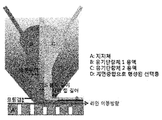
- FIG. 2 is a schematic diagram showing a manufacturing process of a thin film composite separator according to the present invention.
- 3 and 4 are schematic views of a dual-slot die in accordance with the present invention.
- Example 5 is a graph showing the results of evaluating the performance stability of the thin film composite separator prepared in Example.
- the present invention forms a double solution layer by simultaneously applying a first solution containing the first organic monomer and a second solution containing the second organic monomer on the porous support, and between the first organic monomer and the second organic monomer It relates to a method for manufacturing a thin film composite separator comprising the step of forming a selective layer through interfacial polymerization.
- the porous support serves to support the selective layer and to reinforce the mechanical strength of the thin film composite separator.
- the type of the porous support is not particularly limited, and a porous support material used as a thin film composite separator in the art may be used without limitation.
- porous support polyacrylonitrile (PAN), polyvinylidene fluoride (PVDF), cellulose acetate, polyvinylpyrrolidone (PVP), polysulfone (polysulfone, PSF), polyethersulfone (PES), polyimide (PI), polyetherimide (PEI), polybenzoimidazole (PBI), polypropylene (PP) , Polyethylene (PE) or polytetrafluoroethylene (PTFE) may be used.
- the pore size of the porous support may be 1 to 1000 nm, 10 to 100 nm, or 20 to 50 nm. It is excellent in the performance as a separator in the above range.
- the porous support may be one whose surface is not modified or the surface is modified by pretreatment according to the type of the porous support.
- the pretreatment may be carried out oxidation treatment, acid or base treatment, hydrolysis treatment, UV / ozone treatment, plasma treatment or hydrophilic polymer coating.
- hydrophilic polymer in the hydrophilic polymer coating polydopamine, cellulose acetate or polyvinyl alcohol (PVA, polyvinyl alcohol) may be used.
- the oxidation treatment, hydrolysis treatment, UV / ozone treatment, plasma treatment or hydrophilic polymer coating can be carried out through a general process in the art.
- the first solution and the second solution may be a solvent that is immiscible or hybrid.
- a solvent in which the first solution and the second solution are immiscible is used.
- the first solution includes a first organic monomer and a first solvent
- the second solution includes a second organic monomer and a second solvent.
- the first solvent and the second solvent are immiscible and do not mix with each other, so that when the solution layer is formed, the solutions do not mix with each other to form a double layer.
- the first organic monomer and the second organic monomer in the formed double layer may cause a crosslinking reaction through a condensation reaction upon contact.
- the type of the first organic monomer is not particularly limited, and for example, molecules having amine or hydroxyl end groups, diethylene triamine (DETA), triethylene tetramine : TETA), diethyl propyl amine (DEPA), methane diamine (MDA), N-aminoethyl piperazine (N-AEP), M-xylene diamine (M -xylenediamine (MXDA), isophoronediamine (IPDA), m-phenylenediamine (MPD), o-phenylenediamine (OPD), p-phenylenediamine : PPD), 4-4 ⁇ -diaminodiphenyl methane (DDM), 4-4 ⁇ -diaminodiphenyl sulfone (4,4 ⁇ -diaminodiphenyl sulphone (DDS), hydroquinone (hydroquinone), resorcinol, catechol and hydroxyalkylamine It can be selected
- the kind of the first solvent is not particularly limited, and for example, water, methanol, ethanol, propanol, butanol, isopropanol, ethyl acetate, acetone, hexane, pentane, cyclohexane, heptane, octane, carbon tetrachloride,
- One or more selected from the group consisting of benzene, xylene, toluene, tetrahydrofuran and chloroform can be used.
- the type of the second organic monomer is not particularly limited, and for example, a molecule having an acyl chloride end group, trimesoyl chloride (TMC), terephthaloyl chloride, cyclo Hexane-1,3,5-tricarbonyl chloride, 1-isocyanato-3,5-benzenedicarbonyl chloride (1-isocyanato-3,5-benzenedicarbonyl chloride) and isophthaloyl chloride can be used.
- TMC trimesoyl chloride
- terephthaloyl chloride terephthaloyl chloride
- cyclo Hexane-1,3,5-tricarbonyl chloride 1-isocyanato-3,5-benzenedicarbonyl chloride (1-isocyanato-3,5-benzenedicarbonyl chloride) and isophthaloyl chloride
- TMC trimesoyl chloride
- terephthaloyl chloride terephthaloyl chloride
- the kind of the second solvent is not particularly limited, and is selected from the group consisting of hexane, pentane, cyclohexane, heptane, octane, carbon tetrachloride, tetrahydrofuran, benzene, xylene and toluene, for example. You can use more than one.
- a double solution layer is formed by simultaneously applying a first solution including a first organic monomer and a second solution including a second organic monomer on a porous support. Forming; And
- the conventional thin film composite separator manufacturing process (hereinafter, referred to as a two-step manufacturing process or a two-step process) was applied by applying two kinds of solutions on a porous support, thereby forming a selection. Since the production uses a two-step manufacturing process, manufacturing installation cost and manufacturing cost are high, and there is a problem of environmental pollution using a large amount of organic monomers and solvents.
- a dual solution layer is formed through a single process (hereinafter referred to as a one-step manufacturing process or a single process) of simultaneously applying and contacting two immiscible solutions on a porous support, and forming a double solution layer at a double layer interface.
- a single process hereinafter referred to as a one-step manufacturing process or a single process
- a selection layer By synthesizing a selection layer through a crosslinking reaction between organic monomers, a thin film composite separator in which the selection layer is attached to a porous support may be prepared.
- the selection layer may be formed on the surface of the porous support and then attached to the support.
- the simultaneous application of the first solution and the second solution can be carried out via dual (bilayer) -slot coating.
- dual (double layer) -slot coating Through the dual (double layer) -slot coating, a double solution layer having a uniform thickness can be easily formed.
- the coating thickness of the first solution may be 1 to 500 ⁇ m or 50 to 300 ⁇ m
- the coating thickness of the second solution may be 1 to 500 ⁇ m or 50 to 300 ⁇ m.
- the simultaneous application of the first solution and the second solution can be performed using a dual-slot die.
- the dual-slot die may simultaneously apply a first solution and a second solution onto the porous support while moving the porous support along a line.
- the dual-slot die is not particularly limited in structure if it can apply the first solution and the second solution at the same time.
- the dual-slot die may be divided into a first solution compartment and a second solution compartment through a midblock, and each compartment may have a structure in which slits for discharging the solution are formed.
- a solution hereinafter referred to as coating
- the flow rate of the first and second solutions and the line transfer speed of the dual-slot die can be properly adjusted under the coating process conditions.
- the flow rate per coating width of the first solution is 0.016 X 10 -6 to 416.6 X 10 -6 m 2 / s, 1 X 10 -6 to 100 X 10 -6 m 2 / s, 10 X 10 -6 to 50 X 10 -6 m 2 / s , or 15 X 10 -6 to 20 X 10 -6 m, and can be controlled by the 2 / s
- the coating pokdang flow rate of the second solution is 0.016 X 10 -6 to 416.6 X 10 - 6 m 2 / s, 1 X 10 -6 to 100 X 10 -6 m 2 / s, 10 X 10 -6 to 50 X 10 -6 m 2 / s, or 15 X 10 -6 to 20 X 10 -6 Can be controlled by m 2 / s.
- the line movement speed (line speed) of the dual-slot die can be controlled at 1 to 50 m / min, 3 to 10 m / min
- the shape of the dual-slot die can be adjusted so that the coating has a stable flow without vortex generation.
- the length of the mid block may be 50 to 2000 ⁇ m, 200 to 800 ⁇ m, or 400 to 600 ⁇ m.
- the slit thickness of the first solution compartment may be 50 to 1500 ⁇ m, 100 to 500 ⁇ m, or 150 to 300 ⁇ m
- the slit thickness of the second solution compartment is 50 to 1500 ⁇ m, 100 to 500 ⁇ m, or 150 to 300 May be ⁇ m.
- the die lip length, which is the exit portion of the slot die, may be 50-2000 ⁇ m, 500-1000 ⁇ m, or 800-1300 ⁇ m.
- the length of the space (coating gap) between the dual-slot die and the porous support may be 20 to 1000 ⁇ m, 200 to 700 ⁇ m, or 350 to 600 ⁇ m.
- a double solution layer is formed through simultaneous application of the first solution and the second solution, and when the solvents of the first solution and the second solution are immiscible, they are present as a double layer without being mixed with each other. Subsequently, an interfacial polymerization reaction occurs at the interface between the first solution and the second solution.
- the first organic monomer and the second organic monomer may be cross-linked to synthesize a selective layer.
- the first and second solutions are immiscible, but the bilayer and the selective layer can be formed even in the case of a hybrid, and therefore, the first and second solutions are not particularly limited to the case of immiscibility.
- the membrane support may be completed by washing and drying the porous support on which the selective layer is formed, that is, the separator having the selective layer attached thereto.
- the washing can be carried out using the same solvent as the solvent of the second solution, or a solvent which can be used as the second solvent, and drying can be carried out for 1 to 60 minutes at 30 to 80 °C, or 40 to 60 °C Or, for 1 to 40 minutes.
- the present invention also relates to a thin film composite separator prepared by the above-described manufacturing method.
- sodium chloride (NaCl) removal rate may be 70% or more, 80% or more, 90% or more, or 95% or more.
- the thin film composite membrane may be used as a water treatment membrane for seawater desalination, water and sewage treatment, wastewater treatment or softening, or as a gas separation membrane for carbon dioxide removal, soot removal or gas filters.
- porous support a polyacrylonitrile (PAN) support having a pore size of about 20 nm was used.
- PAN polyacrylonitrile
- the support was hydrolyzed at 40 ° C. for 90 minutes in a 2 M NaOH aqueous solution to enhance the hydrophilicity and negative charge properties of the support surface. This serves to enhance the adhesion between the selective layer formed and the porous support.
- M-phenylene diamine (MPD) and water were used as the first organic monomer and the first solvent for dissolving it, respectively, and 0.025, 0.05, 0.1 and 2% MPD aqueous solutions (first solution) were prepared, respectively.
- trimesoyl chloride (TMC) and hexane (n-hexane) were used as second organic monomers and second solvents for dissolving them, respectively, to prepare a 0.1% TMC solution (second solution).
- an aqueous MPD solution (first solution) was poured thereon to impregnate the MPD aqueous solution in the support for about 3 minutes.
- MPD aqueous solution was removed and excess MPD aqueous solution remaining on the support surface was removed.
- the TMC solution (second solution) was poured thereon to induce interfacial polymerization to form a selective layer.
- the membrane surface was washed with hexane and dried at 70 ° C. for about 5 minutes to prepare a thin film composite separator (see FIG. 1).
- the PAN support was fixed in line and a thin film composite separator was prepared using a dual-slot die.
- 3 and 4 show the shape of a dual-slot die in the present invention.
- the flow rates of the MPD aqueous solution and the TMC solution were stabilized.
- the dual solution slot was applied simultaneously on the PAN support while moving the dual-slot die at a constant speed along the line to form a double solution layer.
- the selective layer was synthesized through interfacial polymerization in the double solution layer.
- the resultant was washed with hexane and dried at 50 ° C. for about 30 minutes to prepare a thin film composite separator (see FIG. 2).
- the dual-slot die shape was adjusted based on the stable flow conditions through the conditions of Table 2, so that the flow rate and line speed do not cause vortex.
- the concentration of the aqueous MPD solution (0.025, 0.05, 0.1 and 2%) The performance was compared.
- a 2000 ppm NaCl aqueous solution was permeated through the TFC membrane at room temperature (25 ° C) and high pressure (15.5 bar) conditions so that the water permeability (water permeability) and salt (NaCl) The removal rate was measured.
- the water permeability was calculated from the amount of water permeated per unit area and per hour of membrane, and the NaCl removal rate was calculated by measuring the salt content of the feed and permeate solutions.
- the NaCl removal rate was not more than 98% at any concentration of MPD solution, so it could not be used as a reverse osmosis membrane. This means that a defective selection layer has been made.
- the membrane prepared by the method of Example 1 showed a high NaCl removal rate of 99.1% or more at all MPD aqueous solution concentration. This confirmed that a high performance reverse osmosis membrane was prepared.
- the structure and performance of the selective layer largely depend on the physical and chemical structure of the support.
- the conventional membrane manufacturing process two step process
- low water permeability and NaCl removal rate were observed at low MPD concentration.
- the manufacturing process according to the present invention if only the adhesive force between the selection layer and the support is sufficient, regardless of the type and structure of the support, it is possible to manufacture a high-density selection layer with high separation performance.
- the concentration of the MPD solution decreases, the water permeability is better and higher, and the NaCl removal rate also has an excellent performance, so that a high permeability reverse osmosis membrane can be developed.
- the surface structure of the TFC separator was measured by SEM and AFM images, and the side structure was measured by TEM images.
- the TFC separator prepared by the method of Example 1 was confirmed that the surface roughness is very low compared to Comparative Example 1. Through this, the TFC membrane according to the present invention is expected to reduce membrane fouling that may occur during the separation process.
- the TFC separator manufactured by the method of Example 1 in comparison with the side was thinner and higher in density than Comparative Example 1. That is, the separator according to the present invention is expected to have a relatively superior performance compared to Comparative Example 1.
- the surface structure of the membrane according to the concentration of the MPD aqueous solution (0.025, 0.05, 0.1 and 2%) was measured through the SEM image.
- the thickness of the selective layer was measured, except that a silicon wafer was used instead of the PAN support, and the thickness of the selective layer prepared in the same manner as in Example 1 was measured. The thickness was measured using AFM.
- the TFC separator manufactured by using the manufacturing method according to the present invention can measure the thickness of the selection layer by a simpler method than the method using TEM, using a silicon wafer and AFM.
- the TFC separator prepared by the method of Example 1 the surface roughness decreases as the concentration of the MPD aqueous solution decreases, and the thickness of the selection layer becomes thinner. As a result, a TFC separator having an increasingly superior water permeability is produced.
- the manufacturing method of the present invention has the advantage that an organic analysis of the structure-property-performance of the thin film composite separator is possible.
- the stability was measured for water permeability and NaCl removal for 7 days.
- the separator prepared by the method of Example 1 was confirmed to maintain performance stably without structural defects even under long-term performance measurement conditions.
- a conventional two-step process of manufacturing a thin film composite separator is performed in a single process.
- manufacturing cost and process cost can be reduced, and process time can be shortened, thereby reducing the manufacturing cost of the thin film composite separator.
- the thin film composite separator according to the present invention may be used as a water treatment membrane for seawater desalination, water and sewage treatment, wastewater treatment or softening, or as a gas separation membrane for carbon dioxide removal, soot removal, or gas filters.
Landscapes
- Chemical & Material Sciences (AREA)
- Chemical Kinetics & Catalysis (AREA)
- Engineering & Computer Science (AREA)
- Water Supply & Treatment (AREA)
- Manufacturing & Machinery (AREA)
- Life Sciences & Earth Sciences (AREA)
- Hydrology & Water Resources (AREA)
- Environmental & Geological Engineering (AREA)
- Organic Chemistry (AREA)
- Inorganic Chemistry (AREA)
- Separation Using Semi-Permeable Membranes (AREA)
- Nanotechnology (AREA)
Abstract
본 발명은 박막 복합 분리막(thin film composite membrane, 이하 TFC) 제조 공정에 관한 것으로, 듀얼(이중층)-슬롯코팅 기술을 이용하여 단일(1-step)공정으로 분리막을 제조하는 방법을 제공한다. 본 발명에 따른 듀얼(이중층)-슬롯코팅 공정에서는, 반응성의 두 종류의 유기 단량체가 용해되어있는 비혼성(immiscible)의 두 용액을 다공성 지지체 위에 동시 도포/접촉시키는 단일공정을 통해 이중 용액층을 형성시키고, 이중층 계면에서 유기 단량체간의 가교반응을 통해 선택층을 합성시킴으로써, TFC 분리막을 제조할 수 있다.
Description
본 발명은 수처리(하폐수 처리), 해수담수화 또는 염분차 발전 공정 등에 핵심소재로 사용되는 박막 복합 분리막(Thin Film Composite membrane, 이하 TFC 분리막)의 제조 공정에 관한 것이다.
본 발명을 지원한 국가연구개발사업은 미래창조과학부의 일반연구자지원사업으로서, 연구과제번호 2015010143, 지지체-프리 계면중합법을 이용한 복합분리막 개발이며, 주관기관인 고려대학교 산학협력단이 지원하였다. 또한, 본 발명을 지원한 국가연구개발사업은 환경부의 에코스마트상수도시스템개발 사업으로서, 연구 과제번호 2016002100007, NF/LPRO막 기반 고도정수처리 막오염 제어기술 개발이며, 주관기관인 고려대학교 산학협력단이 지원하였다.
수처리 및 해수담수화 공정 등에 사용되는 박막 복합 분리막은, 다공성 지지체 상에 박막 선택층이 부착되어 있는 박막 복합(Thin Film Composite, TFC) 분리막 형태로 제조되어 왔다.
TFC 분리막의 선택층은, 다공성 지지체 위에서 서로 섞이지 않는 용매 내에 용해되어있는 두 종류의 유기 단량체간의 계면중합을 통해 제조되어왔다. 예를 들어, 상용화 역삼투 분리막의 경우, 폴리술폰(polysulfone) 지지체 위에 아민단량체 수용액과 유기용매(주로 n-hexane)에 용해되어있는 아실클로라이드 단량체 용액을 접촉시켜 계면을 형성시키고, 형성된 계면에서 유기 단량체간의 축합반응을 통해 가교된 폴라아마이드 선택층을 제조해왔다.
이러한 계면 중합 기반의 TFC 분리막 상용화 제조공정은 2단계(2-step)로 이루어져있다. 즉, 제 1 유기 단량체 용액(주로 아민수용액)을 다공성 지지체 위에 도포/함침시키는 제 1 공정과, 제 2 유기 단량체 용액(주로 아실클로라이드 유기용액)을 도포시켜, 계면중합을 유도하는 제 2 공정으로 구성된 2 단계 제조 공정을 통해 TFC 분리막이 제조되어왔다.
예를 들어, 특허문헌 1(미국특허 제4,277,344호)은 일반적인 2단계 공정으로 구성되며, 계면중합을 통해 지지체 위에 폴리아마이드 선택층을 합성하여 TFC 분리막을 제조하는 원천특허이다. 즉, 다공성 지지체 위에 아민 단량체 수용액을 도포/함침(제 1 공정)시키고, 이후, 아실클로라이드 유기용매를 도포(제 2 공정)하여 가교된 폴리아마이드 선택층을 합성한다.
그러나, 2 단계 제조 공정은 제조설비 비용의 상승을 초래할 뿐만 아니라, 제조시간 증가, 공정 복잡화 및 다량의 용매 사용으로 인해 분리막 제조비용이 증가하게 된다. 또한, 상대적으로 많은 양의 폐용매 및 폐화학물질이 방출되어 환경오염 위험성을 증가시킨다.
본 발명은 듀얼(이중층)-슬롯코팅 기술을 활용하여, 다공성 지지체 상에 두 종류의 유기 단량체 용액을 동시에 도포/접촉시켜, 단일 공정(1-step)으로 분리막을 연속적으로 대량 생산하는 방법을 제공하는 것을 목적으로 한다.
본 발명에서는 다공성 지지체 상에 제 1 유기 단량체를 포함하는 제 1 용액 및 제 2 유기 단량체를 포함하는 제 2 용액을 동시에 도포하여 이중 용액층을 형성하고, 상기 제 1 유기 단량체 및 제 2 유기 단량체간의 계면중합을 통해 선택층을 형성하는 단계를 포함하는 박막 복합 분리막의 제조 방법을 제공한다.
본 발명에서는 지지체 상에 두 종류의 유기 단량체 용액들을 차례로 도포/접촉시켜 박막 복합 분리막을 제조하던 기존의 2단계 공정을 단일 공정화한다. 이를 통해 제조설비 비용 및 공정비용을 절감하고, 공정시간을 단축하여, 박막 복합 분리막의 제조단가를 낮출 수 있다.
또한, 용매 및 유기 단량체의 사용을 최소화하여, 화학폐기물의 방출량을 줄여줌으로써, 박막 복합 분리막 제조 공정을 환경친화적인 공정으로 전환할 수 있다.
또한, 기존 제조기술로 고성능의 박막 복합 분리막 제조가 어려웠던 지지체 상에도, 높은 성능의 박막 복합 분리막을 제조할 수 있다. 부가적으로, 제조된 박막 복합 분리막의 특이구조로 인해 내오염성이 향상된 효과를 기대할 수 있다. 즉, 종래 기술로 제조된 분리막 표면은 요철구조가 심한 반면, 본 발명에 따라 제조된 분리막 표면은 매끈하여, 오염에 대한 저항성이 우수하다.
도 1은 종래 박막 복합 분리막의 제조 공정을 나타내는 모식도이다.
도 2는 본 발명에 따른 박막 복합 분리막의 제조 공정을 나타내는 모식도이다.
도 3 및 4는 본 발명에 따른 듀얼-슬롯 다이의 모사도이다.
도 5는 실시예에서 제조된 박막 복합 분리막의 성능 안정성을 평가한 결과를 나타내는 그래프이다.
본 발명은 다공성 지지체 상에 제 1 유기 단량체를 포함하는 제 1 용액 및 제 2 유기 단량체를 포함하는 제 2 용액을 동시에 도포하여 이중 용액층을 형성하고, 상기 제 1 유기 단량체와 제 2 유기 단량체간의 계면중합을 통해 선택층을 형성하는 단계를 포함하는 박막 복합 분리막의 제조 방법에 관한 것이다.
이하, 본 발명의 박막 복합 분리막의 제조 방법을 구체적으로 설명한다.
본 발명에서 다공성 지지체는 선택층을 지지하고 박막 복합 분리막의 기계적 강도를 보강하는 역할을 수행한다. 상기 다공성 지지체의 종류는 특별히 제한되지 않으며, 당업계에서 박막 복합 분리막으로 사용되는 다공성 지지체 소재를 제한없이 사용할 수 있다. 예를 들어, 상기 다공성 지지체로 폴리아크릴로니트릴(polyacrylonitrile, PAN), 폴리비닐리덴 플루오라이드(polyvinylidene fluoride, PVDF), 셀룰로오즈 아세테이트(cellulose acetate), 폴리비닐피롤리돈(polyvinylpyrrolidone, PVP), 폴리술폰(polysulfone, PSF), 폴리에테르술폰(polyethersulfone, PES), 폴리이미드(polyimide, PI), 폴리에터이미드(polyetherimide, PEI), 폴리벤조이미다졸(polybenzoimidazole, PBI), 폴리프로필렌(polypropylene, PP), 폴리에틸렌(polyethylene, PE) 또는 폴리테트라플루오로에틸렌(polytetrafluoroethylene, PTFE)을 사용할 수 있다.
상기 다공성 지지체의 기공 크기는 1 내지 1000 nm, 10 내지 100 nm, 또는 20 내지 50 nm일 수 있다. 상기 범위에서 분리막으로서의 성능이 우수하다.
일 구체예에서, 다공성 지지체는 상기 다공성 지지체의 종류에 따라 표면이 개질되지 않거나, 또는 전처리에 의해 표면이 개질된 것을 사용할 수 있다. 상기 전처리로 산화 처리, 산 또는 염기 처리, 가수분해 처리, UV/오존 처리, 플라즈마 처리 또는 친수성 고분자 코팅을 수행할 수 있다. 상기 친수성 고분자 코팅에서 친수성 고분자로는 폴리도파민, 셀룰로오즈 아세테이트 또는 폴리비닐 알코올(PVA, polyvinyl alcohol)을 사용할 수 있다.
상기 산화 처리, 가수분해 처리, UV/오존 처리, 플라즈마 처리 또는 친수성 고분자 코팅은 당업계의 일반적인 공정을 통해 수행할 수 있다.
본 발명에서 제 1 용액 및 제 2 용액은 비혼성(immiscible) 또는 혼성인 용매일 수 있다. 본 발명에서는 제 1 용액 및 제 2 용액이 비혼성인 용매를 사용하였다.
본 발명에서 제 1 용액은 제 1 유기 단량체 및 제 1 용매를 포함하며, 제 2 용액은 제 2 유기 단량체 및 제 2 용매를 포함한다. 상기 제 1 용매 및 제 2 용매는 비혼성으로 서로 섞이지 않아, 용액층의 형성 시 상기 용액들이 서로 섞이지 않고 이중층을 형성할 수 있다. 또한, 형성된 이중층에서 제 1 유기 단량체 및 제 2 유기 단량체는 접촉시 축합반응을 통한 가교 반응을 일으킬 수 있다.
일 구체예에서, 상기 제 1 유기 단량체의 종류는 특별히 제한되지 않으며, 예를 들어, 아민 또는 하이드록실 말단기를 가지는 분자, 디에틸렌 트리아민(diethylene triamine: DETA), 트리에틸렌 테트라민(triethylene tetramine: TETA), 디에틸아미노 프로필 아민(diethyl propyl amine: DEPA), 메탄 디아민(methane diamine: MDA), N-아미노 에틸 피페라진(N-aminoethyl piperazine: N-AEP), M-자일렌 디아민(M-xylenediamine: MXDA), 이소포론디아민(isophoronediamine: IPDA), m-페닐렌 디아민(m-phenylenediamine: MPD), o-페닐렌 디아민(o-phenylenediamine: OPD), p-페닐렌 디아민(p-phenylenediamine: PPD), 4-4`-디아미노디페닐메탄(4,4`-diaminodiphenyl methane: DDM), 4-4`-디아미노디페닐술폰(4,4`-diaminodiphenyl sulphone: DDS), 하이드로퀴논(hydroquinone), 레소시놀(resorcinol), 카테콜(catechol) 및 하이드록시알킬아민(hydroxyalkylamine)으로 이루어진 그룹으로부터 선택된 하나 이상을 사용할 수 있다.
일 구체예에서, 제 1 용매의 종류는 특별히 제한되지 않으며, 예를 들어, 물, 메탄올, 에탄올, 프로판올, 부탄올, 이소프로판올, 에틸아세테이트, 아세톤, 헥산, 펜탄, 사이클로헥산, 헵탄, 옥탄, 사염화탄소, 벤젠, 자일렌, 톨루엔, 테트라하이드로퓨란 및 클로로포름으로 이루어진 그룹으로부터 선택된 하나 이상을 사용할 수 있다.
일 구체예에서, 제 2 유기 단량체의 종류는 특별히 제한되지 않으며, 예를 들어, 아실클로라이드 말단기를 가지는 분자, 트리메소일 클로라이드(trimesoyl chloride: TMC), 테레프탈로일 클로라이드(terephthaloyl chloride), 시클로헥산-1,3,5-트리카보닐 클로라이드(cyclohexane-1,3,5-tricarbonyl chloride), 1-이소시아네이토-3,5-벤젠디카보닐클로라이드(1-isocyanato-3,5-benzenedicarbonyl chloride) 및 이소프탈로일 클로라이드(isophthaloyl chloride)로 이루어진 그룹으로부터 선택된 하나 이상을 사용할 수 있다.
또한, 일 구체예에서, 제 2 용매의 종류는 특별히 제한되지 않으며, 예를 들어, 헥산, 펜탄, 사이클로헥산, 헵탄, 옥탄, 사염화탄소, 테트라하이드로퓨란, 벤젠, 자일렌 및 톨루엔으로 이루어진 그룹으로부터 선택된 하나 이상을 사용할 수 있다.
본 발명에 따른 박막 복합 분리막의 제조 방법은, 전술한 바와 같이, 다공성 지지체 상에 제 1 유기 단량체를 포함하는 제 1 용액 및 제 2 유기 단량체를 포함하는 제 2 용액을 동시에 도포하여 이중 용액층을 형성하는 단계; 및
상기 제 1 유기 단량체 및 제 2 유기 단량체간의 계면중합을 통해 선택층을 형성하는 단계를 포함한다.
종래 박막 복합 분리막 제조 공정(이하, 2 단계 제조 공정 또는 2 단계 공정이라 할 수 있다)은 다공성 지지체 상에 두 종류의 용액을 차례로 도포시켜, 선택증을 형성하였다. 이와 같은 제조는, 2 단계 제조 공정을 이용하므로 제조설치 비용 및 제조 단가가 높으며, 다량의 유기 단량체 및 용매를 사용하여 환경 오염의 문제가 있다.
또한, 2 단계 제조 공정 에서는 제 1 용액을 다공성 지지체에 도포시킨 후, 지지체 표면에 존재하는 과량의 제 1 용액을 제거하기 때문에, 제 2 용액 도포시 형성되는 선택층은 지지체 표면 또는 표면 아래에서 형성될 우려가 있다.
본 발명에서는 비혼성(immiscible)의 두 용액을 다공성 지지체 상에 동시에 도포 및 접촉시키는 단일 공정(이하, 1 단계 제조 공정 또는 단일 공정이라 할 수 있다)을 통해 이중 용액층을 형성시키고, 이중층 계면에서 유기 단량체 간의 가교반응을 통해 선택층을 합성시킴으로써, 상기 선택층이 다공성 지지체에 부착된 박막 복합 분리막을 제조할 수 있다.
이를 통해 종래 2 단계의 용액 도포 공정을 통해 제조했을 경우 대비 제조설비 비용이 감소되며, 공정을 간소화함으로써, 공정비용을 절감하고, 공정시간을 단축하여 박막 복합 분리막의 제조 단가를 낮출 수 있다. 또한, 용매 및 유기 단량체의 사용을 최소화하여 화학폐기물의 방출량을 줄여줌으로써 환경 친화적이다.
또한, 선택층은 다공성 지지체 표면 상에서 형성된 후, 상기 지지체에 부착될 수 있다.
일 구체예에서, 제 1 용액 및 제 2 용액의 동시 도포는 듀얼(이중층)-슬롯코팅을 통해 수행될 수 있다. 상기 듀얼(이중층)-슬롯코팅을 통해 균일한 두께의 이중 용액층을 용이하게 형성할 수 있다.
일 구체예에서, 상기 제 1 용액의 도포 두께는 1 내지 500 ㎛ 또는 50 내지 300 ㎛일 수 있으며, 제 2 용액의 도포 두께는 1 내지 500 ㎛ 또는 50 내지 300 ㎛일 수 있다.
일 구체예에서, 상기 제 1 용액 및 제 2 용액의 동시 도포는 듀얼-슬롯 다이를 사용하여 수행될 수 있다. 상기 듀얼-슬롯 다이는 일정 라인을 따라 다공성 지지체를 이동하면서, 상기 다공성 지지체 상에 제 1 용액 및 제 2 용액을 동시에 도포할 수 있다.
상기 듀얼-슬롯 다이는 제 1 용액 및 제 2 용액을 동시에 도포할 수 있다면 그 구조는 특별히 제한 되지 않는다. 예를 들어, 상기 듀얼-슬롯 다이는 미드블럭을 통해 제 1 용액 구획 및 제 2 용액 구획으로 분리되며, 각각의 구획에는 용액의 토출을 위한 슬릿이 형성되어 있는 구조를 지닐 수 있다.
일 구체예에서, 듀얼-슬롯 다이를 사용하여 용액을 도포(이하, 코팅이라 할 수 있다)할 경우, 코팅이 와류가 생기지 않고 안정한 흐름을 지니도록 하는 것이 중요하다. 이를 위해 코팅 공정 조건에서 제 1, 2 용액의 유량 및 듀얼-슬롯 다이의 라인 이동 속도를 적절히 조절할 수 있다.
예를 들어, 제 1 용액의 코팅 폭당유량은 0.016 X 10⁻⁶ 내지 416.6 X 10⁻⁶ m2/s, 1 X 10⁻⁶ 내지 100 X 10-6 m2/s, 10 X 10-6 내지 50 X 10-6 m2/s, 또는 15 X 10-6 내지 20 X 10-6 m2/s로 제어할 수 있으며, 제 2 용액의 코팅 폭당유량은 0.016 X 10⁻⁶ 내지 416.6 X 10⁻⁶ m2/s, 1 X 10⁻⁶ 내지 100 X 10-6 m2/s, 10 X 10-6 내지 50 X 10-6 m2/s, 또는 15 X 10-6 내지 20 X 10-6 m2/s 로 제어할 수 있다. 또한, 듀얼-슬롯 다이의 라인 이동 속도(라인 속도)는 1 내지 50 m/min, 3 내지 10 m/min, 또는 5 내지 7 m/min으로 제어할 수 있다.
또한, 일 구체예에서, 코팅이 와류가 생기지 않고 안정한 흐름을 지니도록, 듀얼-슬롯 다이의 형상을 조절할 수 있다.
예를 들어, 미드 블럭의 길이는 50 내지 2000 ㎛, 200 내지 800 ㎛, 또는 400 내지 600 ㎛일 수 있다. 제 1 용액 구획의 슬릿 두께는 50 내지 1500 ㎛, 100 내지 500 ㎛, 또는 150 내지 300 ㎛일 수 있으며, 제 2 용액 구획의 슬릿 두께는 50 내지 1500 ㎛, 100 내지 500 ㎛, 또는 또는 150 내지 300 ㎛일 수 있다. 슬롯 다이의 출구 부분인 다이 립 길이는 50 내지 2000 ㎛, 500 내지 1000 ㎛, 또는 800 내지 1300 ㎛일 수 있다.
또한, 듀얼-슬롯 다이 및 다공성 지지체 사이 공간(코팅 갭)의 길이는 20 내지 1000 ㎛, 200 내지 700 ㎛, 또는 350 내지 600 ㎛일 수 있다.
본 발명에서는 상기 제 1 용액 및 제 2 용액의 동시 도포를 통해 이중 용액층이 형성되며, 상기 제 1 용액 및 제 2 용액의 용매들은 비혼성일 경우 서로 섞이지 않고 이중층으로 존재한다. 그 뒤, 상기 제 1 용액 및 제 2 용액의 계면에서는 계면중합 반응이 일어나는데, 구체적으로 제 1 유기 단량체 및 제 2 유기 단량체가 가교반응하여 선택층이 합성될 수 있다. 일반적으로 제 1, 2 용액은 비혼성이기는 하나, 혼성인 경우에도 이중층 및 선택층 형성이 가능하기 때문에, 특별히 비혼성의 경우에만 한정하지는 않는다.
본 발명에 따른 제조 방법에서는 선택층이 형성된 다공성 지지체, 즉, 선택층이 부착된 분리막을 세척 및 건조하는 단계를 거쳐 분리막 제조를 완성할 수 있다.
일 구체예에서 세척은 제 2 용액의 용매와 동일한 용매, 또는, 제 2 용매로 사용할 수 있는 용매를 사용하여 수행할 수 있으며, 건조는 30 내지 80℃, 또는 40 내지 60℃에서 1 내지 60분, 또는 1 내지 40분 동안 수행할 수 있다.
상기 건조를 통해 분리막 및 선택층이 결합되어 있는 박막 복합 분리막을 최종 제조할 수 있다.
또한, 본 발명은 전술한 제조 방법에 의해 제조된 박막 복합 분리막에 관한 것이다.
본 발명에 따른 박막 복합 분리막은 염화나트륨(NaCl) 제거율이 70% 이상, 80% 이상, 90% 이상, 또는 95% 이상일 수 있다.
상기 박막 복합 분리막은 해수 담수화, 상하수 처리, 폐수 처리 또는 연수화 등을 위한 수처리 분리막으로 사용되거나, 이산화탄소 제거, 매연 제거 또는 기체 필터를 위한 기체 분리막으로 사용될 수 있다.
이하, 본 발명을 하기 실시예에 의해 상세히 설명한다. 단, 하기 실시예는 본 발명을 예시하는 것일 뿐, 본 발명의 내용이 하기 실시예에 한정되는 것은 아니다.
실시예
1. 재료
(a) PAN 다공성 지지체
다공성 지지체로 공극 크기가 약 20 nm인 폴리아크릴로니트릴(PAN) 지지체를 사용하였다. 상기 지지체는 2 M NaOH 수용액에서 40℃ 에서 90분 동안 가수 분해하여, 지지체 표면의 친수성 및 음전하 특성을 강화시켰다. 이는 형성되는 선택층과 다공성 지지체간의 접착력을 강화시키는 역할을 한다.
(b) 계면중합용 유기 단량체 및 용매
제 1 유기 단량체와 이를 용해하는 제 1 용매로 각각 m-페닐렌 디아민(MPD)과 물을 사용하였으며, 0.025, 0.05, 0.1 및 2%의 MPD 수용액(제 1 용액)을 각각 제조하였다.
또한, 제 2 유기 단량체와 이를 용해하는 제 2 용매로 각각 트리메소일 클로라이드(TMC)와 헥산(n-hexane)을 사용하였으며, 0.1%의 TMC 용액(제 2 용액)을 제조하였다.
2. 박막 복합(
TFC
) 분리막 제조
(1)
비교예
1.
2 단계
제조 공정을 통한 박막 복합(
TFC
) 분리막 제조
PAN 지지체를 틀에 고정시킨 후, 그 위에 MPD 수용액(제 1 용액)을 부어 약 3분 동안 지지체내에 MPD 수용액을 함침시켰다. MPD 수용액을 제거하고 지지체 표면에 남은 과량의 MPD 수용액을 제거하였다. 그 위에 TMC 용액(제 2 용액)을 부어 계면중합을 유도하여 선택층을 형성시켰다. 이 후, 헥산을 이용하여 분리막 표면을 세척한 후, 70℃에서 약 5분 동안 건조하여 박막 복합 분리막을 제조하였다(도 1 참조).
(2)
실시예
1.
1 단계
제조 공정(
듀얼
(
이중층
)-슬롯코팅 기술)을 통한 박막 복합(TFC) 분리막 제조
PAN 지지체를 라인에 고정시키고, 듀얼-슬롯 다이를 이용하여 박막 복합 분리막을 제조하였다. 본 발명에서 도 3 및 도 4는 듀얼-슬롯 다이의 형상을 나타낸다.
듀얼-슬롯 다이에 MPD 수용액(제 1 용액)과 TMC 용액(제 2 용액)을 넣은 후, 상기 MPD 수용액과 TMC 용액의 유량을 안정화 시켰다. 유량 안정화 후, 듀얼-슬롯 다이를 라인을 따라 일정한 속도로 이동시키면서, PAN 지지체 위에 두 용액을 동시 도포하여 이중 용액층을 형성시켰다. 이때, 이중 용액층 내 계면중합을 통해 선택층이 합성되었다. 선택층 제조 후, 헥산을 이용하여 세척한 후, 50℃에서 약 30분 동안 건조하여 박막 복합 분리막을 제조하였다(도 2 참조).
슬롯코팅 시, 유량 및 라인 속도의 경우 코팅 중 와류가 생기지 않도록, 하기 표 1의 조건을 통해 안정한 흐름조건에서 진행하였다.

또한, 듀얼-슬롯 다이 형상은 유량과 라인 속도를 와류가 생기지 않도록, 하기 표 2의 조건을 통해 안정한 흐름조건을 바탕으로 조절하였다.

3.
실험예
1. 성능 실험
동일한 PAN 지지체를 사용하여 비교예 1의 방법(2 단계 공정)과 실시예 1의 방법(단일 공정)으로 제조한 TFC 분리막에 대하여, MPD 수용액의 농도(0.025, 0.05, 0.1 및 2%)에 따른 성능을 비교하였다.
구체적으로, Cross-flow filtration 장치를 이용하여, 상온 (25?C) 및 고압 (15.5 bar) 조건에서, 2000 ppm의 NaCl 수용액을 TFC 분리막에 투과시켜 수투과도(유수투과도량) 및 염분(NaCl) 제거율을 측정하였다.
수투과도는 분리막 단위면적당, 단위시간당 투과된 물의 양으로부터 계산하였으며, NaCl 제거율은 공급용액과 투과용액의 염분함유량을 측정하여 계산하였다.
성능 평가 결과를 하기 표 3에 기재하였다.

비교예 1의 방법으로 제조한 분리막의 경우, 어떤 MPD 수용액 농도에서도 NaCl 제거율이 98%를 넘지 못해 역삼투 분리막으로의 사용이 불가능하였다. 이는 결함이 있는 선택층이 만들어 졌음을 의미한다.
반면, 실시예 1의 방법으로 제조한 분리막의 경우, 모든 MPD 수용액 농도에서 99.1% 이상의 높은 NaCl 제거율을 보였다. 이를 통해 고성능 역삼투 분리막이 제조되었음을 확인하였다.
선택층의 구조 및 성능은 지지체의 물리·화학적 구조에 크게 의존한다. 친수성의 PAN 지지체를 사용했을 경우, 기존 분리막 제조 공정(2 단계 공정)은 분리성능이 높은 고밀도의 선택층을 제조하기 어려운 한계를 보인다. 또한 낮은 MPD 수용액의 농도조건 에서는 낮은 수투과도와 NaCl 제거율을 보인다.
반면, 본 발명에 따른 제조 공정의 경우, 선택층과 지지체 간의 접착력만 충분하다면, 지지체 종류 및 구조에 상관없이, 분리성능이 높은 고밀도의 선택층 제조가 가능하다. 또한 MPD 수용액의 농도가 낮아질수록 점점 더 우수한 높은 수투과도를 보이고 NaCl 제거율 또한 우수한 성능을 지니고 있어, 고수투과도의 역삼투 분리막 개발이 가능하다.
4.
실험예
2. 표면구조 및 측면구조 측정
비교예 1 및 실시예 1의 방법으로 제조된 TFC 분리막에 대하여, 2% MPD 수용액을 사용한 경우의 분리막의 구조를 측정하였다.
상기 TFC 분리막의 표면구조는 SEM 및 AFM 이미지를 통해, 측면구조는 TEM 이미지를 통해 측정하였다.
측정 결과를 하기 표 4에 나타내었다.

상기 표 4에 나타난 바와 같이, 실시예 1의 방법으로 제조된 TFC 분리막은 비교예 1에 비해 표면 거칠기가 매우 낮은 것을 확인하였다. 이를 통해 본 발명에 따른 TFC 분리막은 분리공정 중 발생할 수 있는 막 오염성을 줄여줄 수 있을 것으로 기대된다.
또한, 측면 비교시 실시예 1의 방법으로 제조된 TFC 분리막은 비교예 1에 비해 두께가 얇고 밀도가 높았다. 즉, 본 발명에 따른 분리막이 비교예 1 대비 상대적으로 우수한 성능을 가질 것으로 기대된다.
또한, 실시예 1의 방법으로 제조된 TFC 분리막에 대하여, MPD 수용액의 농도(0.025, 0.05, 0.1 및 2%)에 따른 분리막의 표면 구조를 SEM 이미지를 통해 측정하였다.
또한, 선택층의 두께를 측정하였는데, PAN 지지체 대신 실리콘 웨이퍼를 사용한 것을 제외하고는 실시예 1과 동일한 방법으로 제조한 선택층의 두께를 측정하였다. 상기 두께는 AFM을 이용하여 측정하였다.
측정 결과를 하기 표 5에 나타내었다.

본 발명에 따른 제조 방법을 이용하여 제조한 TFC 분리막은 실리콘 웨이퍼와 AFM을 이용하여, TEM을 이용한 방법보다 간단한 방법으로 선택층의 두께를 측정 할 수 있다.
상기 표 5에 나타난 바와 같이, 실시예 1의 방법으로 제조된 TFC 분리막은 MPD 수용액의 농도가 낮아질수록 표면 거칠기가 줄어들고, 선택층의 두께가 점점 얇아진다. 이에 따라 점점 더 우수한 수투과도를 가지는 TFC 분리막이 생성된다.
본 발명의 제조 방법은 박막 복합 분리막에 대한 구조-물성-성능에 관한 유기적인 분석이 가능하다는 장점을 가진다.
5.
실험예
3. 안정성 평가
실시예 1의 방법으로 제조된 TFC 분리막에 대하여, 2% MPD 수용액을 사용한 경우의 분리막의 안정성을 평가하였다.
상기 안정성은 수투과도 및 NaCl 제거율을 7일동안 측정하였다.
수투과도 및 NaCl 제거율은 실험예 1과 같은 방법으로 측정하였다.
그 결과를 도 5에 나타내었다.
상기 도 5에 나타난 바와 같이, 실시예 1의 방법으로 제조된 분리막은 장시간 성능측정조건에서도 구조적 결함없이 안정적으로 성능이 유지됨을 확인하였다.
본 발명에서는 지지체 상에 두 종류의 유기 단량체 용액들을 차례로 도포/접촉시켜 박막 복합 분리막을 제조하던 기존의 2단계 공정을 단일 공정화한다. 이를 통해 제조설비 비용 및 공정비용을 절감하고, 공정시간을 단축하여, 박막 복합 분리막의 제조단가를 낮출 수 있다.
본 발명에 따른 박막 복합 분리막은 해수 담수화, 상하수 처리, 폐수 처리 또는 연수화 등을 위한 수처리 분리막으로 사용되거나, 이산화탄소 제거, 매연 제거 또는 기체 필터를 위한 기체 분리막으로 사용될 수 있다.
Claims (17)
- 다공성 지지체 상에 제 1 유기 단량체를 포함하는 제 1 용액 및 제 2 유기 단량체를 포함하는 제 2 용액을 동시에 도포하여 이중 용액층을 형성하고, 상기 제 1 유기 단량체 및 제 2 유기 단량체간의 계면중합을 통해 선택층을 형성하는 단계를 포함하는 박막 복합 분리막의 제조 방법.
- 제 1 항에 있어서,다공성 지지체는 폴리아크릴로니트릴(polyacrylonitrile, PAN), 폴리비닐리덴 플루오라이드(polyvinylidene fluoride, PVDF), 셀룰로오즈 아세테이트(cellulose acetate), 폴리비닐피롤리돈(polyvinylpyrrolidone, PVP), 폴리술폰(polysulfone, PSF), 폴리에테르술폰(polyethersulfone, PES), 폴리이미드(polyimide, PI), 폴리에터이미드(polyetherimide, PEI), 폴리벤조이미다졸(polybenzoimidazole, PBI), 폴리프로필렌(polypropylene, PP), 폴리에틸렌(polyethylene, PE) 또는 폴리테트라플루오로에틸렌(polytetrafluoroethylene, PTFE)인 박막 복합 분리막의 제조 방법.
- 제 1 항에 있어서,다공성 지지체의 기공 크기는 1 내지 1000 nm인 박막 복합 분리막의 제조 방법.
- 제 1 항에 있어서,다공성 지지체의 표면은 개질되지 않거나, 산화 처리, 산 또는 염기 처리, 가수분해 처리, UV/오존 처리, 플라즈마 처리 또는 친수성 고분자 코팅에 의해 개질된 것인 박막 복합 분리막의 제조 방법.
- 제 4 항에 있어서,친수성 고분자 코팅에서 친수성 고분자는 폴리도파민, 셀룰로오즈 아세테이트 또는 폴리비닐알코올인 박막 복합 분리막의 제조 방법.
- 제 1 항에 있어서,제 1 용액 및 제 2 용액은 비혼성(immiscible) 또는 혼성(miscible)인 박막 복합 분리막의 제조 방법.
- 제 1 항에 있어서,제 1 유기 단량체는 아민 또는 하이드록실 말단기를 가지는 분자, 디에틸렌 트리아민(diethylene triamine: DETA), 트리에틸렌 테트라민(triethylene tetramine: TETA), 디에틸아미노 프로필 아민(diethyl propyl amine: DEPA), 메탄 디아민(methane diamine: MDA), N-아미노 에틸 피페라진(N-aminoethyl piperazine: N-AEP), M-자일렌 디아민(M-xylenediamine: MXDA), 이소포론디아민(isophoronediamine: IPDA), m-페닐렌 디아민(m-phenylenediamine: MPD), o-페닐렌 디아민(o-phenylenediamine: OPD), p-페닐렌 디아민(p-phenylenediamine: PPD), 4-4`-디아미노디페닐메탄(4,4`-diaminodiphenyl methane: DDM), 4-4`-디아미노디페닐술폰(4,4`-diaminodiphenyl sulphone: DDS), 하이드로퀴논(hydroquinone), 레소시놀(resorcinol), 카테콜(catechol) 및 하이드록시알킬아민(hydroxylalkylamine)으로 이루어진 그룹으로부터 선택된 하나 이상인 박막 복합 분리막의 제조 방법.
- 제 1 항에 있어서,제 1 용액의 용매는 물, 메탄올, 에탄올, 프로판올, 부탄올, 이소프로판올, 에틸아세테이트, 아세톤, 헥산, 펜탄, 사이클로헥산, 헵탄, 옥탄, 사염화탄소, 벤젠, 톨루엔, 자일렌, 테트라하이드로퓨란 및 클로로포름으로 이루어진 그룹으로부터 선택된 하나 이상인 박막 복합 분리막의 제조 방법.
- 제 1 항에 있어서,제 2 유기 단량체는 아실클로라이드 말단기를 가지는 분자, 트리메소일 클로라이드(trimesoyl chloride: TMC), 테레프탈로일 클로라이드(terephthaloyl chloride), 시클로헥산-1,3,5-트리카보닐 클로라이드(cyclohexane-1,3,5-tricarbonyl chloride), 1-이소시아네이토-3,5-벤젠디카보닐클로라이드(1-isocyanato-3,5-benzenedicarbonyl chloride) 및 이소프탈로일 클로라이드(isophthaloyl chloride)로 이루어진 그룹으로부터 선택된 하나 이상인 박막 복합 분리막의 제조 방법.
- 제 1 항에 있어서,제 2 용액의 용매는 헥산, 펜탄, 사이클로헥산, 헵탄, 옥탄, 사염화탄소, 테트라하이드로퓨란, 벤젠, 자일렌 및 톨루엔으로 이루어진 그룹으로부터 선택된 하나 이상인 박막 복합 분리막의 제조 방법.
- 제 1 항에 있어서,제 1 용액 및 제 2 용액의 동시 도포는 듀얼(이중층)-슬롯코팅(dual layer-slot coating)을 통해 수행되는 박막 복합 분리막의 제조 방법.
- 제 1 항에 있어서,제 1 용액 및 제 2 용액의 도포 두께는 각각 1 내지 500 ㎛인 박막 복합 분리막의 제조 방법.
- 제 1 항에 있어서,제 1 용액 및 제 2 용액의 동시 도포는 듀얼-슬롯 다이를 사용하여 수행되고,상기 듀얼-슬롯 다이는 미드블럭을 통해 제 1 용액 구획 및 제 2 용액 구획으로 분리되며, 각각의 구획에는 용액의 토출을 위한 슬릿이 형성되어 있는 박막 복합 분리막의 제조 방법.
- 제 13 항에 있어서,제 1 용액 및 제 2 용액의 폭당유량은 각각 0.016 X 10⁻⁶ 내지 416.6 X 10⁻⁶ m2/s인 박막 복합 분리막의 제조 방법.
- 제 13 항에 있어서,듀얼-슬롯 다이의 라인 이동 속도는 1 내지 50 m/min인 박막 복합 분리막의 제조 방법.
- 제 13 항에 있어서,듀얼-슬롯 다이의 미드블럭의 길이는 50 내지 2000 ㎛이고,제 1 용액 구획의 슬릿 두께는 50 내지 1500 ㎛이고, 제 2 용액 구획의 슬릿 두께는 50 내지 1500 ㎛이며,다이 립 길이는 50 내지 2000 ㎛이고,듀얼-슬롯 다이 및 다공성 지지체 사이의 공간(코팅 갭)의 길이는 20 내지 1000 ㎛인 박막 복합 분리막의 제조 방법.
- 제 1 항에 있어서,선택층이 형성된 다공성 지지체를 세척 및 건조하는 단계를 포함하는 박막 복합 분리막의 제조 방법.
Priority Applications (2)
| Application Number | Priority Date | Filing Date | Title |
|---|---|---|---|
| US15/768,431 US20180333684A1 (en) | 2015-12-31 | 2016-11-24 | The one-step preparation process for thin film composite membrane using a dual (double layer)-slot coating technique |
| CN201680059755.6A CN108348866B (zh) | 2015-12-31 | 2016-11-24 | 利用双(双层)-狭缝涂布技术的薄膜复合分离膜的单步骤制备工艺 |
Applications Claiming Priority (2)
| Application Number | Priority Date | Filing Date | Title |
|---|---|---|---|
| KR10-2015-0190720 | 2015-12-31 | ||
| KR1020150190720A KR101804026B1 (ko) | 2015-12-31 | 2015-12-31 | 듀얼(이중층)-슬롯코팅 기술을 이용한 박막 복합 분리막의 단일 제조공정 |
Publications (1)
| Publication Number | Publication Date |
|---|---|
| WO2017116009A1 true WO2017116009A1 (ko) | 2017-07-06 |
Family
ID=59224921
Family Applications (1)
| Application Number | Title | Priority Date | Filing Date |
|---|---|---|---|
| PCT/KR2016/013636 WO2017116009A1 (ko) | 2015-12-31 | 2016-11-24 | 듀얼(이중층)-슬롯코팅 기술을 이용한 박막 복합 분리막의 단일 제조공정 |
Country Status (4)
| Country | Link |
|---|---|
| US (1) | US20180333684A1 (ko) |
| KR (1) | KR101804026B1 (ko) |
| CN (1) | CN108348866B (ko) |
| WO (1) | WO2017116009A1 (ko) |
Families Citing this family (9)
| Publication number | Priority date | Publication date | Assignee | Title |
|---|---|---|---|---|
| KR102198401B1 (ko) * | 2018-04-23 | 2021-01-06 | 고려대학교 산학협력단 | 방향족 탄화수소를 이용한 우수한 용질 제거 성능을 가진 분리막 제조 기술 |
| KR20200114417A (ko) | 2019-03-28 | 2020-10-07 | 주식회사 엘지화학 | 듀얼 슬롯 다이 코터 |
| CN110180402B (zh) * | 2019-07-08 | 2020-08-04 | 清华大学 | 一种基于界面聚合制备松散纳滤膜的方法 |
| WO2021126085A1 (en) * | 2019-12-17 | 2021-06-24 | National University Of Singapore | A smooth thin film composite membrane |
| CN111229050B (zh) * | 2020-01-21 | 2022-02-18 | 吕剑阳 | 一种复合膜的制备方法 |
| KR20220009760A (ko) * | 2020-07-16 | 2022-01-25 | 주식회사 엘지에너지솔루션 | 듀얼 슬롯 다이 코터 |
| CN113199471B (zh) * | 2021-04-07 | 2022-08-30 | 深圳群宾精密工业有限公司 | 一种基于3d视觉对机械手双tcp点胶路径规划的方法 |
| KR102494700B1 (ko) | 2021-07-27 | 2023-02-06 | 충남대학교산학협력단 | 해수담수화용 복합 분리막 및 이의 제조방법 |
| WO2023229390A1 (ko) * | 2022-05-25 | 2023-11-30 | 고려대학교 산학협력단 | 극한 산·염기 안정성을 갖는 수처리용 박막 복합체 분리막의 제조방법 |
Citations (5)
| Publication number | Priority date | Publication date | Assignee | Title |
|---|---|---|---|---|
| KR20110009135A (ko) * | 2008-04-08 | 2011-01-27 | 후지필름 매뉴팩츄어링 유럽 비.브이. | 복합막 |
| KR20140105082A (ko) * | 2013-02-21 | 2014-09-01 | 한국과학기술연구원 | 유기 단량체 간의 가교를 이용한 다층 박막 기반의 역삼투 분리막 및 그 제조방법 |
| KR101519026B1 (ko) * | 2014-02-17 | 2015-05-12 | 한국과학기술연구원 | 유기단량체 간의 가교를 이용한 다층박막기반의 정삼투계 분리막 및 그 제조방법 |
| KR20150060732A (ko) * | 2012-09-26 | 2015-06-03 | 도레이 카부시키가이샤 | 복합 반투막 |
| KR20150099806A (ko) * | 2005-07-10 | 2015-09-01 | 나노에이치투오, 인코포레이티드. | 하이브리드 나노 입자 tfc 멤브레인 |
Family Cites Families (4)
| Publication number | Priority date | Publication date | Assignee | Title |
|---|---|---|---|---|
| US6132804A (en) | 1997-06-06 | 2000-10-17 | Koch Membrane Systems, Inc. | High performance composite membrane |
| US20080004205A1 (en) | 2006-06-30 | 2008-01-03 | Millipore Corporation | Ultrafiltration membranes and methods of making |
| US8557332B2 (en) * | 2006-03-28 | 2013-10-15 | Fujifilm Corporation | Production method of optical film, optical film and image display |
| CN105169970A (zh) * | 2015-09-08 | 2015-12-23 | 武汉大学 | 一种聚多巴胺改性聚酰胺复合正渗透膜的制备方法 |
-
2015
- 2015-12-31 KR KR1020150190720A patent/KR101804026B1/ko active IP Right Grant
-
2016
- 2016-11-24 CN CN201680059755.6A patent/CN108348866B/zh active Active
- 2016-11-24 WO PCT/KR2016/013636 patent/WO2017116009A1/ko active Application Filing
- 2016-11-24 US US15/768,431 patent/US20180333684A1/en not_active Abandoned
Patent Citations (5)
| Publication number | Priority date | Publication date | Assignee | Title |
|---|---|---|---|---|
| KR20150099806A (ko) * | 2005-07-10 | 2015-09-01 | 나노에이치투오, 인코포레이티드. | 하이브리드 나노 입자 tfc 멤브레인 |
| KR20110009135A (ko) * | 2008-04-08 | 2011-01-27 | 후지필름 매뉴팩츄어링 유럽 비.브이. | 복합막 |
| KR20150060732A (ko) * | 2012-09-26 | 2015-06-03 | 도레이 카부시키가이샤 | 복합 반투막 |
| KR20140105082A (ko) * | 2013-02-21 | 2014-09-01 | 한국과학기술연구원 | 유기 단량체 간의 가교를 이용한 다층 박막 기반의 역삼투 분리막 및 그 제조방법 |
| KR101519026B1 (ko) * | 2014-02-17 | 2015-05-12 | 한국과학기술연구원 | 유기단량체 간의 가교를 이용한 다층박막기반의 정삼투계 분리막 및 그 제조방법 |
Also Published As
| Publication number | Publication date |
|---|---|
| US20180333684A1 (en) | 2018-11-22 |
| KR20170079777A (ko) | 2017-07-10 |
| CN108348866B (zh) | 2021-05-25 |
| KR101804026B1 (ko) | 2017-12-28 |
| CN108348866A (zh) | 2018-07-31 |
Similar Documents
| Publication | Publication Date | Title |
|---|---|---|
| WO2017116009A1 (ko) | 듀얼(이중층)-슬롯코팅 기술을 이용한 박막 복합 분리막의 단일 제조공정 | |
| WO2013176524A1 (ko) | 역삼투 분리막 | |
| WO2019209010A1 (ko) | 방향족 탄화수소를 이용한 우수한 용질 제거 성능을 가진 분리막 제조 기술 | |
| WO2016175499A1 (ko) | 지지체-프리 계면중합으로 제조된 선택층을 이용한 분리막의 제조방법 | |
| WO2014204218A2 (ko) | 염제거율 및 투과유량 특성이 우수한 폴리아미드계 수처리 분리막 및 그 제조 방법 | |
| WO2012177033A2 (ko) | 염제거율 및 투과유량 특성이 우수한 역삼투 분리막 및 그 제조방법 | |
| JP6259921B2 (ja) | 複合中空糸膜モジュールおよびその製造方法 | |
| WO2014084661A1 (ko) | 내염소성 고투과 수처리 분리막 및 그 제조 방법 | |
| CN106582318B (zh) | 一种通过氧化石墨烯改性耐有机溶剂纳滤膜、制备方法和应用 | |
| WO2013176523A1 (ko) | 역삼투 분리막 제조방법 및 이에 의해 제조된 역삼투 분리막 | |
| WO2013183969A1 (ko) | 표면 처리된 제올라이트를 포함하는 고투과 유량 역삼투막 및 이를 제조하는 방법 | |
| JP2015500737A (ja) | メンブレン、水処理システム及び製造方法 | |
| WO2013176508A1 (ko) | 초기 투과 유량이 우수한 폴리아미드계 역삼투 분리막 및 이의 제조방법 | |
| WO2017171474A1 (ko) | 폴리아미드 계면중합용 조성물 및 이를 이용한 역삼투막의 제조방법 | |
| WO2014137049A1 (ko) | 내오염성이 우수한 폴리아미드계 수처리 분리막 및 그 제조 방법 | |
| WO2022127637A1 (zh) | 复合反渗透膜及其制备方法 | |
| EP3479891B1 (en) | Composition for forming reverse osmosis membrane protection layer, method for preparing reverse osmosis membrane using same, reverse osmosis membrane, and water treatment module | |
| WO2015099460A1 (ko) | 고성능 폴리아미드계 건식 수처리 분리막 및 그 제조방법 | |
| Yang et al. | Novel solvent-resistant nanofiltration membranes using MPD co-crosslinked polyimide for efficient desalination | |
| CN111974225A (zh) | 一种反渗透膜的制备方法 | |
| US20130292325A1 (en) | Method for preparing reverse osmosis membrane, and reverse osmosis membrane prepared thereby | |
| CN114534491A (zh) | 一种高水通量的反渗透膜及其制备方法和应用 | |
| CN113842783B (zh) | 一种耐酸型高通量聚芳醚复合纳滤膜、制备方法及应用 | |
| KR102384030B1 (ko) | 이황화몰리브덴을 포함하는 유기용매 나노여과 분리막 및 그 제조방법 | |
| WO2018074767A2 (ko) | 역삼투막 보호층 형성용 조성물, 이를 이용한 역삼투막 제조방법, 역삼투막 및 수처리 모듈 |
Legal Events
| Date | Code | Title | Description |
|---|---|---|---|
| 121 | Ep: the epo has been informed by wipo that ep was designated in this application |
Ref document number: 16881962 Country of ref document: EP Kind code of ref document: A1 |
|
| WWE | Wipo information: entry into national phase |
Ref document number: 15768431 Country of ref document: US |
|
| NENP | Non-entry into the national phase |
Ref country code: DE |
|
| 122 | Ep: pct application non-entry in european phase |
Ref document number: 16881962 Country of ref document: EP Kind code of ref document: A1 |