WO2017115402A1 - Article chaussant - Google Patents
Article chaussant Download PDFInfo
- Publication number
- WO2017115402A1 WO2017115402A1 PCT/JP2015/086472 JP2015086472W WO2017115402A1 WO 2017115402 A1 WO2017115402 A1 WO 2017115402A1 JP 2015086472 W JP2015086472 W JP 2015086472W WO 2017115402 A1 WO2017115402 A1 WO 2017115402A1
- Authority
- WO
- WIPO (PCT)
- Prior art keywords
- sole
- support portion
- absorbing unit
- vibration absorbing
- footwear according
- Prior art date
Links
Images


Classifications
-
- A—HUMAN NECESSITIES
- A43—FOOTWEAR
- A43B—CHARACTERISTIC FEATURES OF FOOTWEAR; PARTS OF FOOTWEAR
- A43B7/00—Footwear with health or hygienic arrangements
- A43B7/32—Footwear with health or hygienic arrangements with shock-absorbing means
-
- A—HUMAN NECESSITIES
- A43—FOOTWEAR
- A43B—CHARACTERISTIC FEATURES OF FOOTWEAR; PARTS OF FOOTWEAR
- A43B13/00—Soles; Sole-and-heel integral units
- A43B13/14—Soles; Sole-and-heel integral units characterised by the constructive form
-
- A—HUMAN NECESSITIES
- A43—FOOTWEAR
- A43B—CHARACTERISTIC FEATURES OF FOOTWEAR; PARTS OF FOOTWEAR
- A43B13/00—Soles; Sole-and-heel integral units
- A43B13/14—Soles; Sole-and-heel integral units characterised by the constructive form
- A43B13/18—Resilient soles
- A43B13/181—Resiliency achieved by the structure of the sole
-
- A—HUMAN NECESSITIES
- A43—FOOTWEAR
- A43B—CHARACTERISTIC FEATURES OF FOOTWEAR; PARTS OF FOOTWEAR
- A43B13/00—Soles; Sole-and-heel integral units
- A43B13/14—Soles; Sole-and-heel integral units characterised by the constructive form
- A43B13/18—Resilient soles
- A43B13/187—Resiliency achieved by the features of the material, e.g. foam, non liquid materials
-
- A—HUMAN NECESSITIES
- A43—FOOTWEAR
- A43B—CHARACTERISTIC FEATURES OF FOOTWEAR; PARTS OF FOOTWEAR
- A43B17/00—Insoles for insertion, e.g. footbeds or inlays, for attachment to the shoe after the upper has been joined
- A43B17/003—Insoles for insertion, e.g. footbeds or inlays, for attachment to the shoe after the upper has been joined characterised by the material
-
- A—HUMAN NECESSITIES
- A43—FOOTWEAR
- A43B—CHARACTERISTIC FEATURES OF FOOTWEAR; PARTS OF FOOTWEAR
- A43B17/00—Insoles for insertion, e.g. footbeds or inlays, for attachment to the shoe after the upper has been joined
- A43B17/14—Insoles for insertion, e.g. footbeds or inlays, for attachment to the shoe after the upper has been joined made of sponge, rubber, or plastic materials
-
- A—HUMAN NECESSITIES
- A43—FOOTWEAR
- A43B—CHARACTERISTIC FEATURES OF FOOTWEAR; PARTS OF FOOTWEAR
- A43B5/00—Footwear for sporting purposes
- A43B5/06—Running shoes; Track shoes
Definitions
- the present invention relates to footwear that can suppress vibration generated by landing impact and reduce the influence on the human body.
- the vibration generated by the impact due to landing propagates to the human body at a specific frequency, and the frequency is mainly 200 Hz or less. Since this frequency band includes the resonance frequency (for example, chest 50-100 Hz) of each part of the human body, research reports that it feels uncomfortable. (For example, Non-Patent Document 1).
- Measures to reduce the rigidity of the sole as a countermeasure against this are the conventional methods. Specifically, by making the shape of the shoe sole easily deformable, or by using a soft material such as gel or foam material, the rigidity of the shoe sole is lowered and the shock absorbing performance is increased.
- the cushioning effect must be limited to a certain limit as long as the thickness of the sole is restricted to some extent. Further, when developing a material having a higher buffering effect, there is a difficulty in development because it imposes a condition that the material must also have durability against repeated impacts. Furthermore, while the buffer material can reduce the vibration in a frequency band smaller than around 10 Hz, it is less effective for suppressing the vibration at a higher frequency.
- Patent Literature 1 Japanese Patent No. 290559278 and the like are known as a technique other than a means for reducing the rigidity of a shoe sole in order to improve buffering properties.
- the footwear of Patent Document 1 absorbs vibration energy generated in footwear by arranging a vibration absorbing unit including a vibration absorbing body and a mass body supported by the vibration absorbing body through a support body in a shoe midsole. It is converted into body vibration and absorbed.
- Patent Document 2 Japanese Patent No. 5459741 discloses a technique in which a vibration space portion is provided in a shoe sole and a vibration device is disposed in the vibration space portion.
- the vibration direction of the mass body is not taken into consideration, and as long as the configuration of FIG. 2 is referred to, the mass body has a plurality of directions such as the front-rear direction, the up-down direction, and the diagonal up-down direction. Is thought to vibrate greatly. Therefore, it has been difficult to efficiently suppress vibration propagated to the body during traveling or walking, mainly vibration in the vertical direction.
- the technique of patent document 2 attaches a magnet to the open end of the cantilever diaphragm arrange
- the objective is the interest induction and blood circulation of walking. It is an improvement. That is, no consideration is given to the suppression of vibrations generated in the body during running or walking, and a specific structure for suppressing such vibrations is not disclosed. Further, since the vibration plate is configured to vibrate by receiving an external force by being rejected by a magnet, the vibration is not settled and an unpleasant vibration component remains after landing.
- an object of the present invention is to solve the above-mentioned problems, and to provide footwear that can efficiently remove vibrations of a specific wavelength that propagates to the human body due to landing during running or walking.
- the footwear according to one aspect of the present invention includes a sole, an upper connected to the upper side of the peripheral edge of the sole, and a vibration absorbing unit that absorbs vibration generated by impact caused by landing,
- the vibration absorbing unit includes a plate-like support portion having a vertical rigidity smaller than a horizontal rigidity and having flexibility, and a weight portion provided in the support portion, and the support portion includes: It surrounds the weight part and is fixed to the sole or upper.
- the vibration absorbing unit can be efficiently absorbed in the heel portion where the impact at the time of landing is large by being disposed in a storage space provided inside the heel portion of the sole.
- the fixed position may be provided all around the support portion or may be provided intermittently.
- the opening of the storage space is preferably closed by a protective plate.
- occludes opening is comprised with a transparent or translucent material.
- the support portion When arranging the support portion in the storage space, it can be configured such that the entire periphery is supported by the side wall. By arranging in this way, it becomes easy to adjust the amplitude of the weight part.
- the vibration absorbing unit is arranged with a plurality of the weight portions having different weights, so that vibrations in a plurality of frequency bands are likely to be generated, and vibrations caused by landing impacts corresponding to the respective frequency bands are suppressed. Can do.
- the support portion has a low-rigidity region whose rigidity is lower than that of the periphery at a central portion, and the plurality of weight portions are attached to both sides of the support portion with the low-rigidity region interposed therebetween, so that a plurality of frequency bands are provided.
- the vibration can be more easily generated.
- region can be comprised by the thin part provided in the said support part, Specifically, a groove
- the support portion and the weight portion are integrally formed of the same material, and the weight portion can be formed thicker than the support portion so that the support portion and the weight portion can be integrally formed.
- the production efficiency can be increased.
- the sole is configured by laminating an upper sole and a lower sole, and the support portion can be supported so as to be sandwiched between the upper sole and the lower sole.
- the sole is configured by stacking an upper sole and a lower sole, and the support portion can be integrally formed with the upper sole or the lower sole, so that the support portion and the sole can be integrally formed. Therefore, production efficiency can be increased.
- the sole may have a shank disposed on the arch portion, and the support portion may be formed of a tongue piece extending from the shank toward the heel side.
- the middle foot portion of the sole is configured to be wider than the heel portion, and the vibration absorbing unit is disposed in a storage space provided at the position of the middle foot portion of the sole, thereby taking a large storage space.
- the volume of the weight part can be increased. Thereby, a weight part can be vibrated at a lower frequency, and the shock of a low frequency component can be buffered.
- the weight portion can be disposed so as to be positioned at the arch portion of the arch, and thereby the vibration space is disposed in the middle foot portion having a small contribution to the cushioning property, so that the entire sole can be disposed. It is possible to suppress a decrease in cushioning property. Moreover, the fall of the arch part of the arch can be suppressed by the weight part.
- the upper or the sole is disposed so as to protrude outward with respect to the upper, and includes a mounting base having a holding hole for storing the vibration absorbing unit,
- the vibration absorbing unit may be configured such that the support portion is connected to a peripheral edge of the holding hole and fixed.
- the mounting base can be provided so as to protrude rearward from the collar portion of the upper, or can be provided so as to protrude left and right at a boundary portion between the upper and the sole.
- the vertical rigidity of the support part is preferably 0.1 to 2000 N / m, and the mass of the weight part is preferably 0.001 to 0.030 kg.
- the ratio of the vertical rigidity and the horizontal rigidity value of the support portion is 8 or more.
- the footwear according to one aspect of the present invention is stored in a storage space provided in the sole, an upper connected to the upper peripheral edge of the sole, and generates vibration caused by an impact caused by landing.
- a vibration absorbing unit for absorbing The vibration absorbing unit includes a plate-like support portion that is bent by an impact at the time of landing and a weight portion provided in the support portion, Spaces at least three times as large as the amount of deflection in the vertical direction due to the weight of the vibration absorbing unit are provided above and below the vibration absorbing unit.
- the footwear according to one aspect of the present invention includes a sole, an upper connected to the upper peripheral edge of the sole, and a vibration absorbing unit that absorbs vibration generated by an impact caused by landing,
- the vibration absorbing unit includes a plate-like support portion that is bent by an impact at the time of landing and a weight portion provided in the support portion,
- the support part is made of a material having a vertical rigidity smaller than a horizontal rigidity and having a loss tangent of 0.01 or more under conditions of 25 ° C. and 50 Hz.
- the weight portion since the rigidity in the vertical direction of the support portion is smaller than the rigidity in the horizontal direction, the weight portion largely vibrates mainly in the vertical direction when landing during running or walking. If it does so, the energy by the impact at the time of the landing of the leg
- the support portion is fixed to the sole or upper so as to surround the weight portion, it is easy to control the vibration such as the amplitude of the support portion, and the vibration having a specific frequency can be efficiently removed. it can.
- FIG. 4 is a cross-sectional view taken along line VI-VI in FIG. 3.
- FIG. 5 is a sectional view taken along line VV in FIG. 3.
- FIG. 4 shows typically the attachment structure of the vibrational absorption unit mounted in the athletic shoe of FIG.
- It is sectional drawing which shows the modification of the attachment structure of a mid sole and a vibrational absorption unit.
- FIG. 15 is a side view showing a state in which a load is applied to the sole portion of FIG. 14.
- FIG. 15 is a side view showing a state in which a load is applied to the sole portion of FIG. 14.
- It is a schematic diagram which shows the modification of the athletic shoe of FIG. 14, and is a figure which shows the arrangement position of the vibrational absorption unit seen from the shoe back part.
- It is a side view which shows typically the structure of the athletic shoe concerning 4th Embodiment of this invention.
- It is a side view which shows typically the structure of the athletic shoe concerning 5th Embodiment of this invention.
- It is a top view of the athletic shoe of FIG.
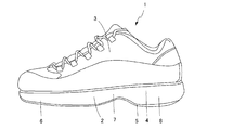
- FIG. 1 is a diagram showing an external configuration of an athletic shoe according to a first embodiment of footwear of the present invention
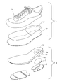
- FIG. 2 is an exploded perspective view of the athletic shoe of FIG.
- An athletic shoe 1 according to this embodiment includes a sole (sole) 2 and an upper (top) 3 connected to the upper side of the sole 2.
- the athletic shoe 1 is formed in a pair of left and right (for right foot and left foot) symmetrical to each other, but only for the left foot is shown in FIGS.
- the sole 2 has a multilayer structure having a midsole 4 and an outer sole 5 as shown in FIG.
- foams such as rubber and resin and non-foams are preferably used.
- the midsole 4 is configured such that an upper midsole 4a and a lower midsole 4b are laminated.
- a laminated structure is formed throughout to form a storage space 10 to be described later, but only the flange portion may be a laminated structure.
- the sole 2 is functionally divided into a front foot part 6, a middle foot part 7 and a heel part 8 in order from the front side.
- the forefoot part 6 and the heel part 8 are in contact with the ground
- the middle foot part 7 is formed so as not to contact the ground, but all of the forefoot part 6, the middle foot part 7 and the heel part 8 are in contact with the ground.
- a so-called flat bottom may be used.
- the forefoot part 6, the middle foot part 7, and the heel part 8 do not need to be clearly delimited in shape, and in the case of a flat bottom, a portion that substantially corresponds to the arch of the user's foot To do.
- the thickness of the sole 2 is not particularly limited and can be appropriately designed according to the use, etc., but as an example, the front foot portion 6 and the middle foot portion 7 can be set to, for example, 5 mm or more and 20 mm or less, In the collar part 8, it can be set as 5 mm or more and 40 mm or less, for example. That is, the thickness of the heel part 8 may be equal to the forefoot part 6 and the middle foot part 7, or may be larger than the forefoot part and the middle foot part 7. Moreover, the thickness of the forefoot part and the middle foot part 7 may differ.
- a storage space 10 having a bottom opening is provided in the heel part 8 of the midsole.
- the opening of the storage space 10 is closed by a protective plate 9.
- the periphery of the protection plate 9 is fixed by being sandwiched between the midsole 4 and the outer sole 5.
- the outer sole 5 is configured in a substantially U shape so that a portion where the protective plate 9 is disposed does not interfere with the protective plate 9.
- the protective plate 9 is translucent. By making the protective plate 9 translucent, it is possible to visually recognize the state such as whether the vibration absorbing unit 14 is damaged.
- Translucent means transparency that allows the inside of the storage space 10 to be visually recognized. For example, it means that the visible light transmittance is 30% or more.
- the upper 3 is connected to the vicinity of the upper peripheral edge of the sole 2 to cover the wearer's foot, the inner sole 12 disposed on the inner bottom surface of the upper cover 11, and to prevent stepping out.
- Insole 13 is provided.
- a metal plate, a synthetic resin plate, a high-strength fiber woven fabric, or the like can be used. Further, although it is attached to the upper side, it may be laminated on the upper surface of the sole and included in the sole.
- any method such as sewing and adhesion can be applied.
- Examples of the material of the upper cover part 11 include natural leather, synthetic leather, woven cloth, and the like, and nails and the like that are not easily penetrated are preferable.
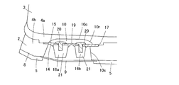
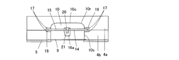
- FIG. 3 is a perspective view of the athletic shoe according to the present embodiment as seen from the shoe sole side. 4 is a cross-sectional view taken along line VI-VI in FIG. FIG. 5 is a cross-sectional view taken along line VV in FIG. As shown in FIG. 3, the athletic shoe 1 according to the present embodiment includes a storage space 10 for storing the vibration absorbing unit 14 in the heel part 8.
- the storage space 10 is a hole opened in the bottom of the shoe provided in the heel part 8 of the sole 2 and is configured by cutting out the midsole 4. Specifically, a through-hole is provided in the flange portion 8 of the lower midsole 4b, a bottomed hole is provided in the upper midsole 4a, and the two are stacked to form a storage space 10 having a predetermined size. Is done.
- the storage space 10 has a substantially elliptical opening.
- the corner 10r of the top surface 10c and the side surface 10s of the storage space 10 has a rounded shape.
- the corner 10r of the top surface 10c and the side surface 10s of the storage space 10 is rounded, the pressure from the foot can be generated in the corner 10r when the midsole 4 is applied.
- the stress concentration can be relaxed and the midsole can be prevented from being broken at the corner 10r.
- the vibration absorbing unit 14 is stored in the storage space 10.
- the vibration absorbing unit 14 includes a plate-like support portion 15 that is bent by an impact at the time of landing, and a weight portion 16 (16a, 16b) provided on the support portion 15.
- the size of the storage space 10 and the vibration absorption unit 14 is configured such that there is a space at least three times larger than the deflection amount of the vibration absorption unit 14 in the vertical direction.
- the deflection amount of the vibration absorption unit 14 means a value obtained by dividing the deflection amount of the support portion 15 by the weight portion 16 weight when the athletic shoe is turned upside down by 2.
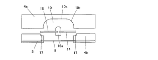
- the vibration absorbing unit 14 is supported such that the entire periphery of the support portion 15 is sandwiched between the upper midsole 4a and the lower midsole 4b of the midsole 4.
- positioning upper recesses 17 are provided in the upper midsole 4 a and the lower midsole 4 b, respectively, and by fixing the support 15 and fixing the entire periphery of the support 15 with the adhesive 18, A support portion 15 is disposed at the boundary between the upper midsole 4a and the lower midsole 4b.
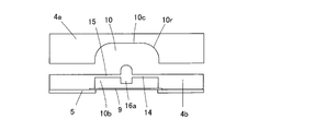
- the positioning recess 17 may be provided only in the lower midsole 4b as shown in FIG. 7, or may be provided only in the upper midsole 4a as shown in FIG.
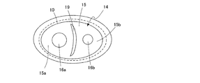
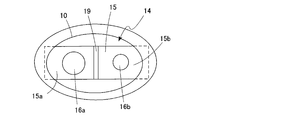
- FIG. 6 is a plan view of the vibration absorbing unit 14.
- the support portion 15 has an outer shape that fits into the positioning recess 17 provided in the midsole 4.
- the support part 15 is comprised with the elliptical thin board which has the flexibility of the grade which bends by the impact at the time of landing.
- a material of the support portion 15 for example, rubber, gel, resin, or the like can be used.
- the support portion 15 is configured so that the bending rigidity in the vertical direction (hereinafter sometimes simply referred to as rigidity) is smaller than the rigidity in the horizontal direction due to its shape or material characteristics.
- the support part 15 receives an impact and bends due to inertia reaching the weight part 16, and vibrates due to the bend.
- the support part 15 is comprised so that rigidity may become small in the perpendicular direction, it has the characteristic that it vibrates greatly in the perpendicular direction.
- the ratio (k h / k p ) between the vertical stiffness k p and the horizontal stiffness k h is preferably 8 or more. It is preferred if the one end fixed the ratio (k h / k p) is 40 or more.
- the natural frequency fn is expressed by the following equation (1).
- n is the order of the vibration mode
- ⁇ is a constant that varies depending on the fixing method and the order.
- equation (2) is derived from equation (1) above.
- k h represents the horizontal rigidity
- k p represents the vertical rigidity
- ⁇ 1 (primary) is 4.730
- ⁇ 2 (secondary) is 7.853 (see Mechanical Engineering Handbook (edited by the Japan Society for Mechanical Engineering)). Therefore, in order that the primary vibration mode in the horizontal direction becomes larger than the secondary vibration mode in the vertical direction when the support portion 15 is fixed at both ends, (k h / k p )> 7.6 is obtained from the equation (2). It is preferable that the ratio between the vertical stiffness and the horizontal stiffness is 8 or more.
- both ends of the support portion 15 refers to both ends of the support portion located on the long axis of the vibration absorbing unit 14 (the longest portion in the planar shape), “One end” of the support portion 15 refers to one end portion of the support portion located on the long axis of the vibration absorbing unit 14.
- a thin portion 19 as an example of a low rigidity region is provided at an intermediate position of the support portion 15. As shown in FIGS. 4 and 6, the thin portion 19 is a groove provided at an intermediate position of the support portion 15, and the portion is configured to be easily bent. Note that the low-rigidity region can be formed by forming a crease instead of a thin-walled portion.
- the weight portions 16 (16a, 16b) are provided in the regions 15a, 15b on both sides of the thin portion 19 of the support portion 15, respectively.
- the weight portions 16 (16a, 16b) are substantially cylindrical weights, and have different weights.
- the vibration absorbing unit 14 Since the weight portions 16a and 16b having different masses are provided across the thin-walled portion 19, the vibration absorbing unit 14 is likely to generate a plurality of different vibration modes, and vibration caused by an impact corresponding to each mode is generated. Can be suppressed.
- the vertical rigidity k p [N / m] of the support portion 15 and the mass m [kg] of the weight portion 16 are set in the following ranges. 0.1 ⁇ k p ⁇ 2000 0.001 ⁇ m ⁇ 0.030
- the vibration absorbing unit fits in a storage space that can be provided in the sole heel portion of a general size athletic shoe. 14 can be used.
- the vertical stiffness k h is a value measured by pushing the center of gravity of the vibration absorbing unit with a spring alone.
- the mass m of the weight portion 16 is the mass of the portion of the vibration absorbing unit excluding the fixed portion of the support portion 15.
- the fixed portion of the support portion 15 is a portion where the support portion 15 is in contact with the sole 2.
- the weight portions 16a and 16b are configured as separate members from the support portion 15, and are detachably attached to predetermined positions of the support portion 15.
- the weight portions 16 a and 16 b are mainly composed of two members, a screw 20 and a receiving portion 21. More specifically, the screw 20 as a male screw located on the upper surface side of the support portion 15 and the receiving portion 21 as a female screw located on the lower surface side of the support portion 15 are screwed together with the support portion sandwiched therebetween. It is fixed. If the weight portion 16 is formed of two or more separable members, either the screw 20 or the receiving portion 21 can be replaced with one having a different weight, for example, a weight suitable for the frequency to be suppressed.
- the degree of freedom in designing the vibration absorbing unit 14 is improved.
- a weight portion 16 having a fitting structure including a protruding protrusion and a receiving portion having a recess into which the protruding portion is fitted can be cited.
- a method for fixing the weight portion 16 to the support portion 15 a method such as an adhesive or heat fusion can be employed in addition to the method of sandwiching the support portion 15 between two members as described above.
- the support part 15 and a weight part can also be integrally comprised by the same material, for example, you may make the said part function as a weight part by comprising a part of support part thickly.
- the support portion 15 and the weight portion 16 can be configured integrally with the midsole 4.
- the support portion 15 is configured integrally with the lower midsole 4 b, and the top surface of the recessed hole 10 b that opens to the lower side of the lower midsole 4 b functions as the support portion 15.
- the thickness dimension of a part of the support part 15 can be configured to be large, and the part can function as a weight part.
- the support portion 15 is made of resin.
- the specific value of loss tangent tan ⁇ is preferably 0.01 or more.
- the support portion 15 of the vibration absorbing unit 14 vibrates with the impact at the time of landing, and the vibration of the weight portion 16 is sufficiently attenuated at the next landing.
- the vibration of the support portion 15 By attenuating the vibration of the support portion 15 itself, the impact at the time of landing can be buffered repeatedly without the vibration radiating at the time of the next landing.
- ⁇ n [rad / s] is the natural frequency in the vertical direction of the support portion 15
- tan ⁇ is the loss tangent tan ⁇ under the conditions of 25 ° C. and 50 Hz.
- Non-Patent Document 1 since the resonance frequency of the chest that the human body feels uncomfortable is 50-100 Hz, under the conditions for buffering these frequencies, the above relationship is satisfied when tan ⁇ exceeds 0.01. Obviously, a material having a tan ⁇ smaller than this value is not preferable. In the present embodiment, for example, a resin material having a tan ⁇ greater than 0.01 is employed as the support portion 16.
- the loss tangent tan ⁇ in this embodiment is obtained by applying a strain of ⁇ 0.025% from the strain of 0% to the tensile or pressure direction using a dynamic viscoelastic device (Rheogel-E4000 manufactured by UBM Co., Ltd.). This is the value when measured.
- the support portion 15 may be configured in a band shape, and both ends of the support portion 15 may be fixed positions so as to sandwich the weight portion 16.
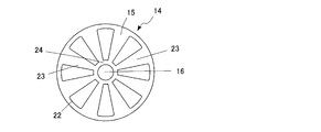
- the vibration absorbing unit 14 does not need to be configured by the thin plate shape of the support portion 15 and can be configured as shown in FIG. 11, for example.
- the support portion 15 is radially outward toward the outer peripheral edge 22 disposed at the opening peripheral edge of the sole storage space 10, the weight attaching portion 24 to which the weight portion 16 is attached, and the weight attaching portion 24. And a plurality of extending support arms 23. The weight portion 16 is attached to the weight attachment portion 24.
- the vibration absorbing unit 14 shown in FIG. 11 is configured to support one weight portion 16 at the center, when the vibration absorbing unit 14 having this configuration is used, a plurality of storage spaces 10 are provided in the sole 4, You may make it arrange
- the weight portion 16 mainly vibrates largely in the vertical direction. By this vibration, the energy caused by the impact at the time of landing of the foot during running or walking is efficiently converted to the vibration energy of the weight part and removed. For this reason, an impact can be efficiently removed by landing, and vibration propagating to the user can be suppressed.
- FIG. 13 is an exploded perspective view schematically showing the configuration of the sole portion of the athletic shoe according to the second embodiment of the present invention.
- the sole 2 includes a shank 26 disposed on the arch portion.
- the shank is a member used for the sole to maintain the arch-like shape of the arch, supports the arch portion from below, and has a hardness that does not cause the arch to collapse with weight.
- a material constituting the shank for example, a metal or a synthetic resin can be used.
- a lower midsole 4b provided only in the buttocks 8 is located.
- the lower midsole 4b is connected so as to be laminated with the upper midsole 4a, and constitutes the midsole 4.
- a storage space 10 for storing the vibration absorbing unit 14 is provided in the collar portion 8 of the midsole 4.
- the storage space 10 is a hole opened in the bottom of the shoe provided in the heel part 8 of the sole 2, and is configured in such a shape that the midsole 4 is cut out.
- a through-hole is provided in the flange portion 8 of the lower midsole 4b, a bottomed hole is provided in the upper midsole 4a, and the two are stacked to form a storage space 10 having a predetermined size. Is done.
- a tongue piece 27 extending toward the heel side is provided behind the shank 26.
- the tongue piece 27 functions as the support portion 15 of the vibration absorbing unit 14, and the rear side of the intermediate portion is located in the storage space 10 and the end portion protrudes from the rear side of the storage space 10. ing. With such a structure, only one end of the support portion 15 is fixed to the shank 26.
- a thin portion 19 as an example of a low rigidity region is provided in the intermediate portion of the tongue piece 27.
- Weight portions 16 (16a, 16b) are provided on both sides of the thin portion 19, respectively.
- the weight portions 16 (16a, 16b) are substantially cylindrical weights, and have different weights.
- the weight portions 16a and 16b are configured as separate members from the support portion 15, and are bonded and fixed to the lower surface side of the support portion 15.
- the portion of the tongue piece 27 located in the storage space 10 functions as the support portion 15 of the vibration absorbing unit 14, and vibrates at a predetermined frequency when receiving an impact due to landing.
- the vibration absorbing unit is fixed since only one end of the support portion 15 is fixed.
- the rigidity in the vertical direction is lower and the vibration is more easily generated.
- the vibration absorbing unit 14 is likely to generate a plurality of different vibration modes, and is caused by an impact corresponding to each mode. Vibration can be suppressed.
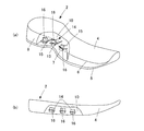
- FIGS. 14A and 14B are views schematically showing a configuration of a sole portion of an athletic shoe (for left foot) according to a third embodiment of the present invention, wherein FIG. 14A is a partial sectional perspective view, and FIG. 14B is a side view. .
- FIG. 15 is a side view showing a state in which a load is applied to the sole portion of FIG.
- the sole 2 is provided with a storage space 10 in the middle foot 7 for storing the vibration absorbing unit 14.
- the vibration absorption unit 14 has a configuration in which three support portions 15 that vibrate at different frequencies are independent, and the support portion 15 is supported on the end side along the width direction of the sole 2. Yes.
- the storage space 10 provided in the sole 2 is provided in the middle foot portion 7 including the arch portion as described above. What is necessary is just to determine the height dimension of the storage space 10 according to the height direction dimension of the weight part 16 which supports the middle leg part 7 so that it may mention later.
- the vibration absorbing unit 14 is configured such that the three independent support portions 15 are supported by the end portions positioned in the width direction, and are arranged substantially in parallel in the front-rear direction.
- the weight portion 16 is arranged so as to be biased toward the end portion so as to be positioned on the arch portion.
- the respective weight parts 16 have different masses, and the frequency at which the support part 15 vibrates is different.
- the support portions 15 vibrate in different modes due to the impact of the ground contact at the time of landing, and vibrations propagating to the human body can be removed. Further, since the storage space 10 for storing the vibration absorbing unit 14 is provided in the middle foot portion 7 including the arch, the storage space 10 is deformed by applying a load from above to the middle foot portion 7 at the time of landing. To do. At this time, as shown in FIG. 15, the weight portion 16 located in the arch portion supports the deformation of the middle foot portion 7 of the arch portion, and it is possible to prevent the arch of the arch portion from being excessively deformed.
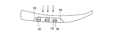
- the athletic shoe according to the present embodiment includes a vibration absorbing unit 14 configured such that the width of the middle foot portion 7 is larger than that of the heel portion 8 and accommodated in the middle foot portion 7 as in the modification shown in FIG. It can also be configured large.
- the flange portion 8 is provided with a buffer member 5c for absorbing a landing impact.
- the vibration absorbing unit 14 is configured to be long by arranging the support portions 15 obliquely. Further, both ends of the support portion 15 are formed in an arc shape so as to follow the shape of the midfoot portion 7 and are disposed in the sole of the midfoot portion 7.
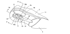
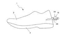
- FIG. 17 is a side view which shows typically the structure of the athletic shoe concerning 4th Embodiment of this invention.
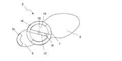
- the athletic shoe 1 according to the present embodiment is different from the above-described embodiment in that the vibration absorbing unit 14 is attached not to the inside of the sole 2 but to the upper side. Specifically, the vibration absorbing unit 14 is attached to a position protruding rearward via an attachment base 24 fixed to the flange portion of the upper 3.
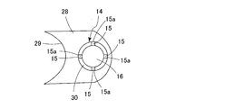
- FIG. 18 is a partially enlarged view schematically showing the mounting configuration of the vibration absorbing unit used in the athletic shoe according to the fourth embodiment.
- the vibration absorbing unit 14 is fixed to a mounting base 28 that is fixed to a flange portion of the upper 3 as a part of the upper 3.
- the mounting base 28 is a plate-like member, and one side is a mounting side 29 configured in an arc shape so as to follow the shape of the flange portion of the upper 3. Further, a holding hole 30 penetrating in the thickness direction is provided, and the vibration absorbing unit 14 is accommodated in the holding hole 30.
- the holding hole 30 is a circular through hole that is opened larger than the weight portion 16, and has an outer end portion 15 a that does not contact the weight portion 16 of the support portion 15 at the periphery.
- the support portion 15 includes four support arms, and a spherical weight portion 16 is fixed to the inner end portion. Thereby, a weight part is arrange
- the number of support arms is not limited to four, and any number may be used as long as the weight portion 16 can be vibrated.
- the support portion 15 having substantially the same shape as the holding hole 30 may be arranged so as to fill the holding hole 30, and the entire outer edge of the support portion 15 may be connected to the mounting base 28.
- the energy generated by the impact at the time of landing of the foot during running or walking is converted into the vibration energy of the weight part, and the vibration propagating to the body can be removed.
- the vibration absorbing unit 14 is provided outside the upper, there is no restriction on the installation space, compared with the case where the vibration absorbing unit 14 is disposed inside the sole 2, the weight portion 16 is easily enlarged, and the function of the sole 2 is hindered. There is nothing.
- the mass m of the weight portion 16 is the mass of the vibration absorbing unit excluding the fixed portion of the support portion 15, and the support portion 15 is in contact with the mounting base 28 with the fixed portion of the support portion 15. Refers to the part.
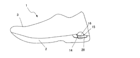
- FIG. 19 is a side view schematically showing the configuration of the athletic shoe according to the fifth embodiment of the present invention.
- FIG. 20 is a plan view schematically showing the configuration of the athletic shoe according to the fifth embodiment.
- the athletic shoe 1 according to the present embodiment is common to the athletic shoe according to the fourth embodiment in that the vibration absorbing unit 14 is provided not on the inside of the sole 2 but on the outside of the upper 3.
- the attachment position of the attachment base 28 to which the unit 14 is attached is different.
- the mounting base 28 is provided at the boundary portion between the upper 3 and the sole 2 so as to protrude on both sides, and houses the structural vibration absorbing unit 14 that is substantially common to the fourth embodiment in the holding hole 30.
- the vibration absorbing unit 14 since the vibration absorbing unit 14 is provided outside the upper, there is no restriction on the installation space, the weight portion 16 is easily enlarged, and the function of the sole 2 is not hindered.
- the deviation in the foot length direction from the center of gravity of the vibration absorbing unit, the load center at the time of heel contact and the foot length direction is small, a large vibration absorbing effect can be expected.
- the present invention is not limited to the above-described embodiments, and can be implemented in various other modes.
- the shape of the weight portion 16 is not limited to a cylindrical shape or a spherical shape, and may be configured in a prismatic shape, a disc shape, or the like.
Abstract
Priority Applications (4)
| Application Number | Priority Date | Filing Date | Title |
|---|---|---|---|
| JP2017558804A JP6710704B2 (ja) | 2015-12-28 | 2015-12-28 | 履物 |
| US16/066,643 US11058170B2 (en) | 2015-12-28 | 2015-12-28 | Footwear |
| PCT/JP2015/086472 WO2017115402A1 (fr) | 2015-12-28 | 2015-12-28 | Article chaussant |
| EP15912068.2A EP3398467B1 (fr) | 2015-12-28 | 2015-12-28 | Article chaussant |
Applications Claiming Priority (1)
| Application Number | Priority Date | Filing Date | Title |
|---|---|---|---|
| PCT/JP2015/086472 WO2017115402A1 (fr) | 2015-12-28 | 2015-12-28 | Article chaussant |
Publications (1)
| Publication Number | Publication Date |
|---|---|
| WO2017115402A1 true WO2017115402A1 (fr) | 2017-07-06 |
Family
ID=59224711
Family Applications (1)
| Application Number | Title | Priority Date | Filing Date |
|---|---|---|---|
| PCT/JP2015/086472 WO2017115402A1 (fr) | 2015-12-28 | 2015-12-28 | Article chaussant |
Country Status (4)
| Country | Link |
|---|---|
| US (1) | US11058170B2 (fr) |
| EP (1) | EP3398467B1 (fr) |
| JP (1) | JP6710704B2 (fr) |
| WO (1) | WO2017115402A1 (fr) |
Cited By (1)
| Publication number | Priority date | Publication date | Assignee | Title |
|---|---|---|---|---|
| CN109430998A (zh) * | 2018-11-14 | 2019-03-08 | 浙江工贸职业技术学院 | 一种降温减震运动鞋 |
Families Citing this family (1)
| Publication number | Priority date | Publication date | Assignee | Title |
|---|---|---|---|---|
| US11399594B2 (en) * | 2013-05-07 | 2022-08-02 | Danielle M Kassatly | Footwear auxiliaries for synchronously toning leg muscles in order to straighten back posture |
Citations (8)
| Publication number | Priority date | Publication date | Assignee | Title |
|---|---|---|---|---|
| JPH01303334A (ja) * | 1987-10-05 | 1989-12-07 | Asics Corp | 緩衝部材 |
| JPH0723804A (ja) * | 1993-07-13 | 1995-01-27 | Yamaha Corp | スポーツシューズ |
| JPH07313203A (ja) * | 1994-05-26 | 1995-12-05 | Toyohiko Nishibe | 履物本底 |
| JPH09273582A (ja) * | 1996-04-02 | 1997-10-21 | Bridgestone Corp | 衝撃吸収部材 |
| JPH11506027A (ja) * | 1995-05-30 | 1999-06-02 | ザ ロックポート カンパニー,インコーポレイテッド | 靴底用のインサート |
| JP2007530308A (ja) * | 2003-07-16 | 2007-11-01 | ナイキ・インコーポレーテッド | 分岐した流体充填チャンバーを組み込んだ底部構造を有する履物 |
| JP2010525918A (ja) * | 2007-05-09 | 2010-07-29 | グ キム,ソン | 機能性履物 |
| JP5459741B2 (ja) * | 2009-09-21 | 2014-04-02 | ウェルネスヒルズ、インコーポレイテッド | 振動が発生する履物およびその振動装置 |
Family Cites Families (10)
| Publication number | Priority date | Publication date | Assignee | Title |
|---|---|---|---|---|
| JP2905928B2 (ja) | 1989-11-30 | 1999-06-14 | 株式会社シーゲル | 靴底における振動吸収装置 |
| US20060157901A1 (en) * | 2001-08-27 | 2006-07-20 | Sting Free Company | Vibration dampening material and method of making same |
| US7234250B2 (en) * | 2005-02-07 | 2007-06-26 | Stacy Renee Fogarty | Convertible traction shoes |
| US20080066348A1 (en) * | 2005-02-07 | 2008-03-20 | Select Sole, Llc | Footwear with retractable members |
| US8008363B2 (en) * | 2005-05-10 | 2011-08-30 | Asics Corporation | Shoe sole component |
| US8056261B2 (en) * | 2007-07-20 | 2011-11-15 | Wolverine World Wide, Inc. | Footwear sole construction |
| US8307572B2 (en) * | 2009-09-21 | 2012-11-13 | Nike, Inc. | Protective boot |
| US9210967B2 (en) * | 2010-08-13 | 2015-12-15 | Nike, Inc. | Sole structure with traction elements |
| US9009991B2 (en) * | 2011-06-23 | 2015-04-21 | Nike, Inc. | Article of footwear with a cavity viewing system |
| CA2822759A1 (fr) | 2013-08-05 | 2015-02-05 | Richard Patrick Desmarais | Chaussure comportant un coussinage entre la semelle et la tige |
-
2015
- 2015-12-28 WO PCT/JP2015/086472 patent/WO2017115402A1/fr active Application Filing
- 2015-12-28 US US16/066,643 patent/US11058170B2/en active Active
- 2015-12-28 JP JP2017558804A patent/JP6710704B2/ja active Active
- 2015-12-28 EP EP15912068.2A patent/EP3398467B1/fr active Active
Patent Citations (8)
| Publication number | Priority date | Publication date | Assignee | Title |
|---|---|---|---|---|
| JPH01303334A (ja) * | 1987-10-05 | 1989-12-07 | Asics Corp | 緩衝部材 |
| JPH0723804A (ja) * | 1993-07-13 | 1995-01-27 | Yamaha Corp | スポーツシューズ |
| JPH07313203A (ja) * | 1994-05-26 | 1995-12-05 | Toyohiko Nishibe | 履物本底 |
| JPH11506027A (ja) * | 1995-05-30 | 1999-06-02 | ザ ロックポート カンパニー,インコーポレイテッド | 靴底用のインサート |
| JPH09273582A (ja) * | 1996-04-02 | 1997-10-21 | Bridgestone Corp | 衝撃吸収部材 |
| JP2007530308A (ja) * | 2003-07-16 | 2007-11-01 | ナイキ・インコーポレーテッド | 分岐した流体充填チャンバーを組み込んだ底部構造を有する履物 |
| JP2010525918A (ja) * | 2007-05-09 | 2010-07-29 | グ キム,ソン | 機能性履物 |
| JP5459741B2 (ja) * | 2009-09-21 | 2014-04-02 | ウェルネスヒルズ、インコーポレイテッド | 振動が発生する履物およびその振動装置 |
Cited By (2)
| Publication number | Priority date | Publication date | Assignee | Title |
|---|---|---|---|---|
| CN109430998A (zh) * | 2018-11-14 | 2019-03-08 | 浙江工贸职业技术学院 | 一种降温减震运动鞋 |
| CN109430998B (zh) * | 2018-11-14 | 2020-11-03 | 浙江工贸职业技术学院 | 一种降温减震运动鞋 |
Also Published As
| Publication number | Publication date |
|---|---|
| US20180368514A1 (en) | 2018-12-27 |
| EP3398467A1 (fr) | 2018-11-07 |
| JP6710704B2 (ja) | 2020-06-17 |
| US11058170B2 (en) | 2021-07-13 |
| EP3398467B1 (fr) | 2022-02-23 |
| JPWO2017115402A1 (ja) | 2018-10-18 |
| EP3398467A4 (fr) | 2019-08-28 |
Similar Documents
| Publication | Publication Date | Title |
|---|---|---|
| EP2911542B1 (fr) | Structure de semelle avec couches de ressort et d'amortissement alternées | |
| US7937854B2 (en) | Article of footwear having force attenuation membrane | |
| US8640361B2 (en) | Sport footwear | |
| JP4704429B2 (ja) | 靴底の緩衝装置 | |
| EP2197309B1 (fr) | Chaussure avec une structure de semelle | |
| EP2023760B1 (fr) | Éléments d'atténuation d'impact présentant une stabilité des forces latérales et de cisaillement et produits contenant des éléments de ce type | |
| US7748141B2 (en) | Article of footwear with support assemblies having elastomeric support columns | |
| US20080256827A1 (en) | Sole Unit for Footwear and Footwear Incorporating Same | |
| US20140150298A1 (en) | Articles of footwear | |
| WO2017115402A1 (fr) | Article chaussant | |
| EP2088886B1 (fr) | Article chaussant avec structure de support tubulaire | |
| JP5331809B2 (ja) | 衝撃吸収材付き履物 | |
| JP2007089734A (ja) | 靴底の緩衝構造、その製造方法および設計方法 | |
| JPH09285304A (ja) | 靴 底 | |
| JP5403782B2 (ja) | 中敷及び履物 | |
| KR20140093097A (ko) | 운동화용 아웃솔 | |
| JP4685840B2 (ja) | 靴底 | |
| KR101451377B1 (ko) | 충격흡수 기능을 갖는 신발 | |
| KR200251082Y1 (ko) | 신발 | |
| TWI459910B (zh) | 球鞋 | |
| JP5901080B2 (ja) | 緩衝板及びこの緩衝板を内蔵した靴 |
Legal Events
| Date | Code | Title | Description |
|---|---|---|---|
| 121 | Ep: the epo has been informed by wipo that ep was designated in this application |
Ref document number: 15912068 Country of ref document: EP Kind code of ref document: A1 |
|
| ENP | Entry into the national phase |
Ref document number: 2017558804 Country of ref document: JP Kind code of ref document: A |
|
| NENP | Non-entry into the national phase |
Ref country code: DE |
|
| WWE | Wipo information: entry into national phase |
Ref document number: 2015912068 Country of ref document: EP |
|
| ENP | Entry into the national phase |
Ref document number: 2015912068 Country of ref document: EP Effective date: 20180730 |