WO2017115402A1 - Footwear - Google Patents

Footwear Download PDF

Info

Publication number
WO2017115402A1
WO2017115402A1 PCT/JP2015/086472 JP2015086472W WO2017115402A1 WO 2017115402 A1 WO2017115402 A1 WO 2017115402A1 JP 2015086472 W JP2015086472 W JP 2015086472W WO 2017115402 A1 WO2017115402 A1 WO 2017115402A1
Authority
WO
WIPO (PCT)
Prior art keywords
sole
support portion
absorbing unit
vibration absorbing
footwear according
Prior art date
Application number
PCT/JP2015/086472
Other languages
French (fr)
Japanese (ja)
Inventor
西脇 剛史
翔 ▲高▼増
弘毅 松尾
雄大郎 岩佐
滋之 三ッ井
克則 柳生
Original Assignee
株式会社アシックス
Priority date (The priority date is an assumption and is not a legal conclusion. Google has not performed a legal analysis and makes no representation as to the accuracy of the date listed.)
Filing date
Publication date
Application filed by 株式会社アシックス filed Critical 株式会社アシックス
Priority to US16/066,643 priority Critical patent/US11058170B2/en
Priority to EP15912068.2A priority patent/EP3398467B1/en
Priority to PCT/JP2015/086472 priority patent/WO2017115402A1/en
Priority to JP2017558804A priority patent/JP6710704B2/en
Publication of WO2017115402A1 publication Critical patent/WO2017115402A1/en

Links

Images

Classifications

    • AHUMAN NECESSITIES
    • A43FOOTWEAR
    • A43BCHARACTERISTIC FEATURES OF FOOTWEAR; PARTS OF FOOTWEAR
    • A43B7/00Footwear with health or hygienic arrangements
    • A43B7/32Footwear with health or hygienic arrangements with shock-absorbing means
    • AHUMAN NECESSITIES
    • A43FOOTWEAR
    • A43BCHARACTERISTIC FEATURES OF FOOTWEAR; PARTS OF FOOTWEAR
    • A43B13/00Soles; Sole-and-heel integral units
    • A43B13/14Soles; Sole-and-heel integral units characterised by the constructive form
    • AHUMAN NECESSITIES
    • A43FOOTWEAR
    • A43BCHARACTERISTIC FEATURES OF FOOTWEAR; PARTS OF FOOTWEAR
    • A43B13/00Soles; Sole-and-heel integral units
    • A43B13/14Soles; Sole-and-heel integral units characterised by the constructive form
    • A43B13/18Resilient soles
    • A43B13/181Resiliency achieved by the structure of the sole
    • AHUMAN NECESSITIES
    • A43FOOTWEAR
    • A43BCHARACTERISTIC FEATURES OF FOOTWEAR; PARTS OF FOOTWEAR
    • A43B13/00Soles; Sole-and-heel integral units
    • A43B13/14Soles; Sole-and-heel integral units characterised by the constructive form
    • A43B13/18Resilient soles
    • A43B13/187Resiliency achieved by the features of the material, e.g. foam, non liquid materials
    • AHUMAN NECESSITIES
    • A43FOOTWEAR
    • A43BCHARACTERISTIC FEATURES OF FOOTWEAR; PARTS OF FOOTWEAR
    • A43B17/00Insoles for insertion, e.g. footbeds or inlays, for attachment to the shoe after the upper has been joined
    • A43B17/003Insoles for insertion, e.g. footbeds or inlays, for attachment to the shoe after the upper has been joined characterised by the material
    • AHUMAN NECESSITIES
    • A43FOOTWEAR
    • A43BCHARACTERISTIC FEATURES OF FOOTWEAR; PARTS OF FOOTWEAR
    • A43B17/00Insoles for insertion, e.g. footbeds or inlays, for attachment to the shoe after the upper has been joined
    • A43B17/14Insoles for insertion, e.g. footbeds or inlays, for attachment to the shoe after the upper has been joined made of sponge, rubber, or plastic materials
    • AHUMAN NECESSITIES
    • A43FOOTWEAR
    • A43BCHARACTERISTIC FEATURES OF FOOTWEAR; PARTS OF FOOTWEAR
    • A43B5/00Footwear for sporting purposes
    • A43B5/06Running shoes; Track shoes

Landscapes

  • Health & Medical Sciences (AREA)
  • General Health & Medical Sciences (AREA)
  • Epidemiology (AREA)
  • Public Health (AREA)
  • Chemical & Material Sciences (AREA)
  • Engineering & Computer Science (AREA)
  • Materials Engineering (AREA)
  • Footwear And Its Accessory, Manufacturing Method And Apparatuses (AREA)
  • Physical Education & Sports Medicine (AREA)
  • Life Sciences & Earth Sciences (AREA)
  • Wood Science & Technology (AREA)

Abstract

Provided is footwear that is capable of effectively removing vibrations of particular wavelengths which are propagated in the body when landing during running or walking. The footwear (1) includes: a sole (2); an upper (3) that is connected to the top of a peripheral part of the sole (2); and a vibration absorbing unit (14) that absorbs vibrations generated by the impact of landing. The vibration absorbing unit (14) includes: a flexible plate-like support portion (15) which has a vertical rigidity that is lower than a horizontal rigidity; and a weight portion (16) provided in the support portion (15). The secured position of the support portion (15) to the sole (2) or the upper (3) is located so as to surround the weight portion (16).

Description

履物footwear
 本発明は、着地衝撃により発生する振動を抑え、人体への影響を軽減することができる履物に関するものである。 The present invention relates to footwear that can suppress vibration generated by landing impact and reduce the influence on the human body.
 ジョギング、マラソン等が盛んに行われる今日では、舗装された道路を走ることも多く、そのため着地の際に繰り返して受ける衝撃が人体に対して悪影響を及ぼすことが知られている。 Today, when jogging, marathons, etc. are frequently performed, it is often run on paved roads, so it is known that repeated impacts on landing cause adverse effects on the human body.
 着地による衝撃によって生じる振動は、人体にも特定周波数の振動が伝播し、その周波数は主として200Hz以下である。この周波数帯域は、人体の各部位の共振周波数(例えば胸部50-100Hz)を含むため、不快に感じるとの研究報告がなされている。(例えば、非特許文献1)。 The vibration generated by the impact due to landing propagates to the human body at a specific frequency, and the frequency is mainly 200 Hz or less. Since this frequency band includes the resonance frequency (for example, chest 50-100 Hz) of each part of the human body, research reports that it feels uncomfortable. (For example, Non-Patent Document 1).
 この対策として靴底の剛性を小さくするアプローチが従来からの一般的な方法である。具体的には、靴底の形状を変形しやすい構造にしたり、ゲルやフォーム材などの柔らかい材料を用いたりすることにより、靴底の剛性を低下させ、衝撃緩衝性能を高くしている。 Measures to reduce the rigidity of the sole as a countermeasure against this are the conventional methods. Specifically, by making the shape of the shoe sole easily deformable, or by using a soft material such as gel or foam material, the rigidity of the shoe sole is lowered and the shock absorbing performance is increased.
 しかし、靴底に緩衝素材を用いる方法では、靴底の厚さがある程度制約されている以上、その緩衝効果も一定限度にとどまらざるを得ない。また、より緩衝効果の高い素材を開発する場合にも、繰り返して受ける衝撃に対してその素材が耐久性をも兼ね備えなければならないという条件が課せられることから開発上の困難があった。さらに、緩衝素材では10Hz付近より小さい周波数帯域の振動に対しては小さくすることができる一方で、それ以上の周波数の振動抑制には効果が小さい。 However, in the method using a cushioning material for the sole, the cushioning effect must be limited to a certain limit as long as the thickness of the sole is restricted to some extent. Further, when developing a material having a higher buffering effect, there is a difficulty in development because it imposes a condition that the material must also have durability against repeated impacts. Furthermore, while the buffer material can reduce the vibration in a frequency band smaller than around 10 Hz, it is less effective for suppressing the vibration at a higher frequency.
 一方、緩衝性を向上させるために、靴底の剛性を小さくする手段以外の技術としては、特許文献1(特許第2905928号公報)などが知られている。特許文献1の履物は、吸振体と、支承体を介して吸振体に支持される質量体とからなる振動吸収ユニットを靴のミッドソール内に配置することで、履物に生じた振動エネルギーを吸振体の振動に変換して吸収するものである。 On the other hand, Patent Literature 1 (Japanese Patent No. 29055928) and the like are known as a technique other than a means for reducing the rigidity of a shoe sole in order to improve buffering properties. The footwear of Patent Document 1 absorbs vibration energy generated in footwear by arranging a vibration absorbing unit including a vibration absorbing body and a mass body supported by the vibration absorbing body through a support body in a shoe midsole. It is converted into body vibration and absorbed.
 また、特許文献2(特許第5459741号公報)には、靴底に振動空間部を設け、振動空間部に振動装置を配置した技術が開示されている。 Further, Patent Document 2 (Japanese Patent No. 5459741) discloses a technique in which a vibration space portion is provided in a shoe sole and a vibration device is disposed in the vibration space portion.
特許第2905928号公報Japanese Patent No. 29052828 特許第5459741号公報Japanese Patent No. 5459741
 しかし、特許文献1の振動吸収ユニットでは、質量体の振動方向について考慮されておらず、図2の構成を参照する限り、質量体が前後方向、上下方向、斜め上下方向など複数の方向に対して大きく振動すると考えられる。したがって、走行時あるいは歩行時に身体に伝播される振動、主に鉛直方向の振動を効率よく抑えることが困難であった。 However, in the vibration absorption unit of Patent Document 1, the vibration direction of the mass body is not taken into consideration, and as long as the configuration of FIG. 2 is referred to, the mass body has a plurality of directions such as the front-rear direction, the up-down direction, and the diagonal up-down direction. Is thought to vibrate greatly. Therefore, it has been difficult to efficiently suppress vibration propagated to the body during traveling or walking, mainly vibration in the vertical direction.
 また、特許文献2の技術は、振動空間に配置された片持ちの振動板の開放端に磁石を取り付け、磁力を用いて振動板を振動させるものであり、その目的は歩行の興味誘発および血行改善である。すなわち、走行時あるいは歩行時に身体に発生する振動の抑制については何ら考慮されておらず、当然それらの振動を抑えるための具体的な構造も開示されていない。また、振動板が磁石で排斥されて外力を受けて振動する構成であるため、振動が収まらず、着地後に不快な振動成分が残ってしまう。 Moreover, the technique of patent document 2 attaches a magnet to the open end of the cantilever diaphragm arrange | positioned in vibration space, and vibrates a diaphragm using magnetic force, The objective is the interest induction and blood circulation of walking. It is an improvement. That is, no consideration is given to the suppression of vibrations generated in the body during running or walking, and a specific structure for suppressing such vibrations is not disclosed. Further, since the vibration plate is configured to vibrate by receiving an external force by being rejected by a magnet, the vibration is not settled and an unpleasant vibration component remains after landing.
 従って、本発明の目的は、上記問題を解決することにあって、走行時あるいは歩行時の着地により人体に伝播する特定波長の振動を効率よく除去することができる履物を提供することにある。 Accordingly, an object of the present invention is to solve the above-mentioned problems, and to provide footwear that can efficiently remove vibrations of a specific wavelength that propagates to the human body due to landing during running or walking.
 上記目的を達成するため、以下の履物を提供する。
 本発明の一態様に係る履物は、ソールと、前記ソールの周縁部上側に接続されるアッパーと、着地による衝撃で発生する振動を吸収する振動吸収ユニットとを備え、
 前記振動吸収ユニットは、鉛直方向の剛性が水平方向の剛性よりも小さく構成され可撓性を有する板状の支持部と、前記支持部に設けられた重量部とを備え、前記支持部は、前記重量部の周囲を取り囲み、前記ソール又はアッパーに対して固定されている。
In order to achieve the above object, the following footwear is provided.
The footwear according to one aspect of the present invention includes a sole, an upper connected to the upper side of the peripheral edge of the sole, and a vibration absorbing unit that absorbs vibration generated by impact caused by landing,
The vibration absorbing unit includes a plate-like support portion having a vertical rigidity smaller than a horizontal rigidity and having flexibility, and a weight portion provided in the support portion, and the support portion includes: It surrounds the weight part and is fixed to the sole or upper.
 上記構成において、前記振動吸収ユニットは、前記ソールの踵部分内部に設けられた収納空間内に配置することにより、着地時の衝撃が大きい踵部分において効率的に振動を吸収することができる。 In the above-described configuration, the vibration absorbing unit can be efficiently absorbed in the heel portion where the impact at the time of landing is large by being disposed in a storage space provided inside the heel portion of the sole.
 上記構成において、固定位置は、支持部の全周に設けられていてもよいし、間欠的に設けられていてもよい。 In the above configuration, the fixed position may be provided all around the support portion or may be provided intermittently.
 また、前記収納空間を前記ソールの下面側に開口するように構成することにより、振動吸収ユニットの動作を容易に確認することができる。ここで、振動吸収ユニットが外部の異物などに接触して破損することを防止するために、収納空間の開口は、保護板により閉塞することが好ましい。なお、開口を閉塞する保護板は、透明又は半透明の材料で構成することが収納空間内の視認の観点から好ましい。 Further, by configuring the storage space so as to open to the lower surface side of the sole, the operation of the vibration absorbing unit can be easily confirmed. Here, in order to prevent the vibration absorbing unit from being damaged due to contact with an external foreign object or the like, the opening of the storage space is preferably closed by a protective plate. In addition, it is preferable from a viewpoint of visual recognition in a storage space that the protective plate which obstruct | occludes opening is comprised with a transparent or translucent material.
 支持部を収納空間内に配置するにあたり、その全周が側壁に支持するように構成することができる。このように配置することにより、重量部の振幅を調整することが容易となる。 When arranging the support portion in the storage space, it can be configured such that the entire periphery is supported by the side wall. By arranging in this way, it becomes easy to adjust the amplitude of the weight part.
 また、前記振動吸収ユニットは、重量の異なる複数の前記重量部を配置することで、複数の周波数帯域の振動が発生しやすくなり、それぞれの周波数帯域に応じた着地衝撃に起因する振動を抑えることができる。 In addition, the vibration absorbing unit is arranged with a plurality of the weight portions having different weights, so that vibrations in a plurality of frequency bands are likely to be generated, and vibrations caused by landing impacts corresponding to the respective frequency bands are suppressed. Can do.
 また、前記支持部は中央部分に周囲よりも剛性の低い低剛性領域を有し、前記複数の重量部は、前記低剛性領域を挟んで前記支持部の両側に取り付けることにより、複数の周波数帯域の振動をより発生させやすくすることができる。なお、前記低剛性領域は、前記支持部に設けられた薄肉部で構成することができ、具体的には、溝や折り目などを薄肉部とすることができる。 In addition, the support portion has a low-rigidity region whose rigidity is lower than that of the periphery at a central portion, and the plurality of weight portions are attached to both sides of the support portion with the low-rigidity region interposed therebetween, so that a plurality of frequency bands are provided. The vibration can be more easily generated. In addition, the said low-rigidity area | region can be comprised by the thin part provided in the said support part, Specifically, a groove | channel, a crease | fold, etc. can be made into a thin part.
 前記振動吸収ユニットは、前記支持部と重量部が同一材料により一体に構成され、前記重量部は前記支持部よりも肉厚に構成することにより支持部と重量部を一体形成することができるために生産効率を上げることができる。 In the vibration absorbing unit, the support portion and the weight portion are integrally formed of the same material, and the weight portion can be formed thicker than the support portion so that the support portion and the weight portion can be integrally formed. The production efficiency can be increased.
 前記ソールは、上側ソールと下側ソールが積層して構成されており、前記支持部を、前記上側ソールと下側ソールとの間に挟持するように支持することができる。このように支持部を配置することにより、簡単かつ確実に収納空間内に振動吸収ユニットを配置させることができる。 The sole is configured by laminating an upper sole and a lower sole, and the support portion can be supported so as to be sandwiched between the upper sole and the lower sole. By arranging the support portion in this way, the vibration absorbing unit can be arranged easily and reliably in the storage space.
 前記ソールは、上側ソールと下側ソールが積層して構成されており、前記支持部は、前記上側ソール又は下側ソールと一体に構成することで、支持部とソールを一体形成することができるために生産効率を上げることができる。 The sole is configured by stacking an upper sole and a lower sole, and the support portion can be integrally formed with the upper sole or the lower sole, so that the support portion and the sole can be integrally formed. Therefore, production efficiency can be increased.
 前記ソールは、土踏まずの部分に配置されるシャンクを有し、前記支持部は、当該シャンクから踵側に伸びる舌片で構成することができる。 The sole may have a shank disposed on the arch portion, and the support portion may be formed of a tongue piece extending from the shank toward the heel side.
 また、前記ソールの中足部を踵部分よりも幅広に構成し、前記振動吸収ユニットを、前記ソールの中足部の位置に設けられた収納空間内に配置することで、収納空間を広く取ることができ、重量部の体積を大きくすることができる。これにより、重量部をより低い周波数で振動させることができ、低周波成分の衝撃を緩衝することができる。 In addition, the middle foot portion of the sole is configured to be wider than the heel portion, and the vibration absorbing unit is disposed in a storage space provided at the position of the middle foot portion of the sole, thereby taking a large storage space. The volume of the weight part can be increased. Thereby, a weight part can be vibrated at a lower frequency, and the shock of a low frequency component can be buffered.
 上記構成において、前記重量部は、前記土踏まずのアーチ部分に位置するように配置することができ、これにより、クッション性への寄与度が小さい中足部に振動空間を配置することで、ソール全体のクッション性低下を抑制することができる。また、重量部によって土踏まずのアーチ部分の落ち込みを抑制することができる。 In the above-described configuration, the weight portion can be disposed so as to be positioned at the arch portion of the arch, and thereby the vibration space is disposed in the middle foot portion having a small contribution to the cushioning property, so that the entire sole can be disposed. It is possible to suppress a decrease in cushioning property. Moreover, the fall of the arch part of the arch can be suppressed by the weight part.
 なお、前記アッパー又はソールは、前記アッパーに対して外側へ突出するように配置され、前記振動吸収ユニットを収納する保持孔を有する取り付けベースを備え、
 前記振動吸収ユニットは、前記支持部が前記保持孔の周縁に連結して、固定されるように構成されていてもよい。また、取り付けベースは、前記アッパーの踵部に後方に突出して設けたり、前記アッパーとソールの境界部分に左右に突出するように設けることができる。
The upper or the sole is disposed so as to protrude outward with respect to the upper, and includes a mounting base having a holding hole for storing the vibration absorbing unit,
The vibration absorbing unit may be configured such that the support portion is connected to a peripheral edge of the holding hole and fixed. Further, the mounting base can be provided so as to protrude rearward from the collar portion of the upper, or can be provided so as to protrude left and right at a boundary portion between the upper and the sole.
 なお、前記支持部の鉛直方向の剛性は、0.1から2000N/m、かつ、前記重量部の質量は0.001から0.030kgとすることが好ましい。 The vertical rigidity of the support part is preferably 0.1 to 2000 N / m, and the mass of the weight part is preferably 0.001 to 0.030 kg.
 また、前記支持部の鉛直方向の剛性と前記水平方向の剛性の値の比は8以上とすることが好ましい。 In addition, it is preferable that the ratio of the vertical rigidity and the horizontal rigidity value of the support portion is 8 or more.
 また、本発明の一態様に係る履物は、ソールと、前記ソールの周縁部上側に接続されるアッパーと、前記ソール内に設けられた収納空間内に収納され、着地による衝撃で発生する振動を吸収する振動吸収ユニットとを備え、
 前記振動吸収ユニットは、着地時の衝撃によって撓む板状の支持部と前記支持部に設けられた重量部を備え、
 前記振動吸収ユニットの自重による鉛直方向のたわみ量の3倍以上の空間が前記振動吸収ユニットの上下に設けられている。
The footwear according to one aspect of the present invention is stored in a storage space provided in the sole, an upper connected to the upper peripheral edge of the sole, and generates vibration caused by an impact caused by landing. A vibration absorbing unit for absorbing,
The vibration absorbing unit includes a plate-like support portion that is bent by an impact at the time of landing and a weight portion provided in the support portion,
Spaces at least three times as large as the amount of deflection in the vertical direction due to the weight of the vibration absorbing unit are provided above and below the vibration absorbing unit.
 また、本発明の一態様に係る履物は、ソールと、前記ソールの周縁部上側に接続されるアッパーと、着地による衝撃で発生する振動を吸収する振動吸収ユニットとを備え、
 前記振動吸収ユニットは、着地時の衝撃によって撓む板状の支持部と前記支持部に設けられた重量部を備え、
 前記支持部は、鉛直方向の剛性が水平方向の剛性よりも小さく構成され、損失正接が25℃、50Hzの条件下で0.01以上である材料で構成されている。
The footwear according to one aspect of the present invention includes a sole, an upper connected to the upper peripheral edge of the sole, and a vibration absorbing unit that absorbs vibration generated by an impact caused by landing,
The vibration absorbing unit includes a plate-like support portion that is bent by an impact at the time of landing and a weight portion provided in the support portion,
The support part is made of a material having a vertical rigidity smaller than a horizontal rigidity and having a loss tangent of 0.01 or more under conditions of 25 ° C. and 50 Hz.
 上記構成を有する履物によれば、支持部の鉛直方向の剛性が水平方向の剛性よりも小さいことから、走行や歩行における着地時に重量部が主として鉛直方向に大きく振動することとなる。そうすると走行時あるいは歩行時における足の着地時の衝撃によるエネルギーを効率よく吸収することができ、身体に伝播する振動を除去することができる。 According to the footwear having the above-described configuration, since the rigidity in the vertical direction of the support portion is smaller than the rigidity in the horizontal direction, the weight portion largely vibrates mainly in the vertical direction when landing during running or walking. If it does so, the energy by the impact at the time of the landing of the leg | foot at the time of a run or a walk can be absorbed efficiently, and the vibration which propagates to a body can be removed.
 また、支持部が重量部の周囲を取り囲むようにソール又はアッパーへ固定されていることにより、支持部の振幅などの振動を制御しやすくし、特定周波数を有する振動の除去を効率よく行うことができる。 In addition, since the support portion is fixed to the sole or upper so as to surround the weight portion, it is easy to control the vibration such as the amplitude of the support portion, and the vibration having a specific frequency can be efficiently removed. it can.
本発明の履物の実施形態にかかる運動靴の外観構成を模式的に示す図である。It is a figure which shows typically the external appearance structure of the athletic shoes concerning embodiment of the footwear of this invention. 図1の運動靴の分解斜視図である。It is a disassembled perspective view of the athletic shoe of FIG. 図1の運動靴を靴底からみた構成を模式的に示す図である。It is a figure which shows typically the structure which looked at the athletic shoes of FIG. 1 from the shoe sole. 図3のVI-VI線における断面図である。FIG. 4 is a cross-sectional view taken along line VI-VI in FIG. 3. 図3のV-V線における断面図である。FIG. 5 is a sectional view taken along line VV in FIG. 3. 図1の運動靴に搭載される振動吸収ユニットの取り付け構成を模式的に示す図である。It is a figure which shows typically the attachment structure of the vibrational absorption unit mounted in the athletic shoe of FIG. ミッドソールと振動吸収ユニットの取り付け構成の変形例を示す断面図である。It is sectional drawing which shows the modification of the attachment structure of a mid sole and a vibrational absorption unit. ミッドソールと振動吸収ユニットの取り付け構成の他の変形例を示す断面図である。It is sectional drawing which shows the other modification of the attachment structure of a mid sole and a vibrational absorption unit. ミッドソールと支持部及び重量部を一体的に構成した他の変形例を示す断面図である。It is sectional drawing which shows the other modification which comprised the mid sole, the support part, and the weight part integrally. 図1の運動靴に搭載される振動吸収ユニットの変形例の構成を模式的に示す図である。It is a figure which shows typically the structure of the modification of the vibrational absorption unit mounted in the athletic shoe of FIG. 図1の運動靴に搭載される振動吸収ユニットの他の変形例の構成を模式的に示す図である。It is a figure which shows typically the structure of the other modification of the vibrational absorption unit mounted in the athletic shoe of FIG. 図1の運動靴に搭載される振動吸収ユニットのさらなる他の変形例の構成を模式的に示す図である。It is a figure which shows typically the structure of the further another modification of the vibrational absorption unit mounted in the athletic shoe of FIG. 第2実施形態にかかる運動靴のソール部分の構成を模式的に示す分解斜視図である。It is a disassembled perspective view which shows typically the structure of the sole part of the athletic shoe concerning 2nd Embodiment. 本発明の第3実施形態にかかる運動靴のソール部分の構成を模式的に示す図であり、(a)は部分断面斜視図、(b)は側面図である。It is a figure which shows typically the structure of the sole part of the athletic shoes concerning 3rd Embodiment of this invention, (a) is a fragmentary sectional perspective view, (b) is a side view. 図14のソール部分に荷重がかかった状態を示す側面図である。FIG. 15 is a side view showing a state in which a load is applied to the sole portion of FIG. 14. 図14の運動靴の変形例を示す模式図であり、靴裏部分からみた振動吸収ユニットの配置位置を示す図である。It is a schematic diagram which shows the modification of the athletic shoe of FIG. 14, and is a figure which shows the arrangement position of the vibrational absorption unit seen from the shoe back part. 本発明の第4実施形態にかかる運動靴の構成を模式的に示す側面図である。It is a side view which shows typically the structure of the athletic shoe concerning 4th Embodiment of this invention. 図17の運動靴に用いられる振動吸収ユニットの取り付け構成を模式的に示す部分拡大図である。It is the elements on larger scale which show typically the attachment structure of the vibrational absorption unit used for the athletic shoes of FIG. 本発明の第5実施形態にかかる運動靴の構成を模式的に示す側面図である。It is a side view which shows typically the structure of the athletic shoe concerning 5th Embodiment of this invention. 図19の運動靴の平面図である。It is a top view of the athletic shoe of FIG.
(第1実施形態)
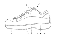
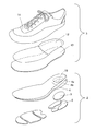
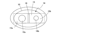
 図1は、本発明の履物の第1実施形態にかかる運動靴の外観構成を示す図であり、図2は、図1の運動靴の分解斜視図である。本実施形態にかかる運動靴1は、ソール(靴底)2とこのソール2の上側に接続されるアッパー(甲被)3とを備える。運動靴1は、互いに対称な左右一対(右足用及び左足用)に形成されるが、図1及び図2には左足用のみを示す。
(First embodiment)
FIG. 1 is a diagram showing an external configuration of an athletic shoe according to a first embodiment of footwear of the present invention, and FIG. 2 is an exploded perspective view of the athletic shoe of FIG. An athletic shoe 1 according to this embodiment includes a sole (sole) 2 and an upper (top) 3 connected to the upper side of the sole 2. The athletic shoe 1 is formed in a pair of left and right (for right foot and left foot) symmetrical to each other, but only for the left foot is shown in FIGS.
 本実施形態において、ソール2は図2に示すように、ミッドソール4及びアウターソール5を有する多層構造で構成されている。ソール2の材質としては、例えばゴム、樹脂等の発泡体および非発泡体が好適に用いられる。 In the present embodiment, the sole 2 has a multilayer structure having a midsole 4 and an outer sole 5 as shown in FIG. As the material of the sole 2, for example, foams such as rubber and resin and non-foams are preferably used.
 ミッドソール4は、上側ミッドソール4aと下側ミッドソール4bとが積層した状態に構成されている。本実施形態においては、後述する収納空間10を形成するために全体にわたって積層構造となっているが、踵部分のみを積層構造としてもよい。 The midsole 4 is configured such that an upper midsole 4a and a lower midsole 4b are laminated. In the present embodiment, a laminated structure is formed throughout to form a storage space 10 to be described later, but only the flange portion may be a laminated structure.
 ソール2は、前側から順に前足部6、中足部7及び踵部8に機能的に分けられる。通常、前足部6及び踵部8が地面に当接し、中足部7は地面に当接しないよう形成されるが、前足部6、中足部7及び踵部8の全てが地面に当接するいわゆる平底であってもよい。ソール2において、前足部6、中足部7及び踵部8は、形状において明確に境界が定められる必要はなく、平底の場合はユーザーの足の土踏まずに略対応する部分を中足部7とする。 The sole 2 is functionally divided into a front foot part 6, a middle foot part 7 and a heel part 8 in order from the front side. Usually, the forefoot part 6 and the heel part 8 are in contact with the ground, and the middle foot part 7 is formed so as not to contact the ground, but all of the forefoot part 6, the middle foot part 7 and the heel part 8 are in contact with the ground. A so-called flat bottom may be used. In the sole 2, the forefoot part 6, the middle foot part 7, and the heel part 8 do not need to be clearly delimited in shape, and in the case of a flat bottom, a portion that substantially corresponds to the arch of the user's foot To do.
 ソール2の厚さとしては、特に限定されず、用途などに応じて適宜設計することができるが、一例として、前足部6及び中足部7においては例えば5mm以上20mm以下とすることができ、踵部8においては例えば5mm以上40mm以下とすることができる。つまり、踵部8の厚さは、前足部6及び中足部7と等しくてもよく、前足部及び中足部7よりも大きくてもよい。また、前足部と中足部7との厚さが異なってもよい。 The thickness of the sole 2 is not particularly limited and can be appropriately designed according to the use, etc., but as an example, the front foot portion 6 and the middle foot portion 7 can be set to, for example, 5 mm or more and 20 mm or less, In the collar part 8, it can be set as 5 mm or more and 40 mm or less, for example. That is, the thickness of the heel part 8 may be equal to the forefoot part 6 and the middle foot part 7, or may be larger than the forefoot part and the middle foot part 7. Moreover, the thickness of the forefoot part and the middle foot part 7 may differ.
 また、ミッドソールの踵部8には、底側開口の収納空間10が設けられている。収納空間10の開口は保護板9によって閉塞されている。保護板9は、その周囲がミッドソール4とアウターソール5の間に挟まれて固定されている。アウターソール5は、当該保護板9が配置される部分が保護板9と干渉しないように、略U字型に構成されている。本実施形態において、保護板9は半透明である。保護板9を半透明にすることによって、振動吸収ユニット14が破損していないかなどその状態を視認することができる。なお、半透明とは収納空間10の内部が視認できる程度の透明度のことをいい、例えば、可視光線透過率が30%以上のことをいう。 Further, a storage space 10 having a bottom opening is provided in the heel part 8 of the midsole. The opening of the storage space 10 is closed by a protective plate 9. The periphery of the protection plate 9 is fixed by being sandwiched between the midsole 4 and the outer sole 5. The outer sole 5 is configured in a substantially U shape so that a portion where the protective plate 9 is disposed does not interfere with the protective plate 9. In the present embodiment, the protective plate 9 is translucent. By making the protective plate 9 translucent, it is possible to visually recognize the state such as whether the vibration absorbing unit 14 is damaged. Translucent means transparency that allows the inside of the storage space 10 to be visually recognized. For example, it means that the visible light transmittance is 30% or more.
 アッパー3は、ソール2の上側の周縁部近傍に接続されて、着用者の足を被覆する上被部11と、上被部11の内部底面に配置されるインナーソール12と、踏み抜き防止のためのインソール13を備える。インソール13としては、例えば金属板、合成樹脂板、高強度繊維製織布等を使用することができる。また、アッパー側に取り付けているが、ソールの上面に積層してソールに含めるようにしてもよい。 The upper 3 is connected to the vicinity of the upper peripheral edge of the sole 2 to cover the wearer's foot, the inner sole 12 disposed on the inner bottom surface of the upper cover 11, and to prevent stepping out. Insole 13 is provided. As the insole 13, for example, a metal plate, a synthetic resin plate, a high-strength fiber woven fabric, or the like can be used. Further, although it is attached to the upper side, it may be laminated on the upper surface of the sole and included in the sole.
 ソール2とアッパー3との接続方法としては、縫い合わせ、接着等の任意の方法を適用することができる。 As a method for connecting the sole 2 and the upper 3, any method such as sewing and adhesion can be applied.
 上被部11の材質としては、例えば天然皮革、合成皮革、織布等が挙げられ、釘等が容易に貫通しないものが好ましい。 Examples of the material of the upper cover part 11 include natural leather, synthetic leather, woven cloth, and the like, and nails and the like that are not easily penetrated are preferable.
 図3は、本実施形態にかかる運動靴を靴底側からみた斜視図である。図4は、図3のVI-VI線における断面図である。図5は、図3のV-V線における断面図である。図3に示すように、本実施形態にかかる運動靴1は、踵部8に振動吸収ユニット14を収納するための収納空間10を備えている。 FIG. 3 is a perspective view of the athletic shoe according to the present embodiment as seen from the shoe sole side. 4 is a cross-sectional view taken along line VI-VI in FIG. FIG. 5 is a cross-sectional view taken along line VV in FIG. As shown in FIG. 3, the athletic shoe 1 according to the present embodiment includes a storage space 10 for storing the vibration absorbing unit 14 in the heel part 8.
 収納空間10は、ソール2の踵部8に設けられる靴底面に開口した孔であり、ミッドソール4をくり抜いて構成されている。具体的には、下側ミッドソール4bの踵部8に貫通孔を設け、上側ミッドソール4aに有底孔を設け、両者を積層することで、所定の寸法に構成された収納空間10が形成される。 The storage space 10 is a hole opened in the bottom of the shoe provided in the heel part 8 of the sole 2 and is configured by cutting out the midsole 4. Specifically, a through-hole is provided in the flange portion 8 of the lower midsole 4b, a bottomed hole is provided in the upper midsole 4a, and the two are stacked to form a storage space 10 having a predetermined size. Is done.
 図3に示すように収納空間10は略楕円形の開口を有している。また図4、図5の断面図に示すように収納空間10の天面10cと側面10sとの角部10rは丸みを帯びた形状となっている。このように収納空間10の天面10cと側面10sとの角部10rを丸みを帯びた形状とすることによって、足からの圧力がミッドソール4に付加された際に角部10rに発生し得る応力集中を緩和させて、角部10rにおいてミッドソールが破損するのを抑制することができる。 As shown in FIG. 3, the storage space 10 has a substantially elliptical opening. Further, as shown in the cross-sectional views of FIGS. 4 and 5, the corner 10r of the top surface 10c and the side surface 10s of the storage space 10 has a rounded shape. Thus, when the corner 10r of the top surface 10c and the side surface 10s of the storage space 10 is rounded, the pressure from the foot can be generated in the corner 10r when the midsole 4 is applied. The stress concentration can be relaxed and the midsole can be prevented from being broken at the corner 10r.
 収納空間10の内部には、振動吸収ユニット14が収納される。振動吸収ユニット14は、着地時の衝撃によって撓む板状の支持部15と、支持部15に設けられた重量部16(16a,16b)を備える。 The vibration absorbing unit 14 is stored in the storage space 10. The vibration absorbing unit 14 includes a plate-like support portion 15 that is bent by an impact at the time of landing, and a weight portion 16 (16a, 16b) provided on the support portion 15.
 収納空間10と振動吸収ユニット14との大きさは、上下に振動吸収ユニット14のたわみ量の3倍以上の空間があくように構成されていることが好ましい。このように構成することにより、後述するように振動吸収ユニット14が鉛直方向に振動したとしても、重量部16の収納空間16上下壁への衝突を防ぐことができ、振動吸収ユニット14の効果的な振動を確保することができる。なお、ここで振動吸収ユニット14のたわみ量は、運動靴を上下逆においたときの重量部16重量による支持部15のたわみ量を2で除した値を意味する。 It is preferable that the size of the storage space 10 and the vibration absorption unit 14 is configured such that there is a space at least three times larger than the deflection amount of the vibration absorption unit 14 in the vertical direction. With this configuration, even when the vibration absorbing unit 14 vibrates in the vertical direction as described later, it is possible to prevent the weight portion 16 from colliding with the upper and lower walls of the storage space 16, and the vibration absorbing unit 14 is effective. Can be ensured. Here, the deflection amount of the vibration absorption unit 14 means a value obtained by dividing the deflection amount of the support portion 15 by the weight portion 16 weight when the athletic shoe is turned upside down by 2.
 振動吸収ユニット14は、図4,図5に示すようにミッドソール4の上側ミッドソール4aと下側ミッドソール4bとの間に支持部15の周縁全周が挟持されるように支持される。図5の例では、上側ミッドソール4aと下側ミッドソール4bにそれぞれ位置決め用の凹部17が設けられ、当該支持部15を嵌めて接着剤18で支持部15の全周を固定することにより、上側ミッドソール4aと下側ミッドソール4bの境界に支持部15が配置される。ただし、位置決め凹部17は、図7に示すように下側ミッドソール4bのみに設けてもよいし、図8に示すように上側ミッドソール4aのみに設けてもよい。 4 and 5, the vibration absorbing unit 14 is supported such that the entire periphery of the support portion 15 is sandwiched between the upper midsole 4a and the lower midsole 4b of the midsole 4. In the example of FIG. 5, positioning upper recesses 17 are provided in the upper midsole 4 a and the lower midsole 4 b, respectively, and by fixing the support 15 and fixing the entire periphery of the support 15 with the adhesive 18, A support portion 15 is disposed at the boundary between the upper midsole 4a and the lower midsole 4b. However, the positioning recess 17 may be provided only in the lower midsole 4b as shown in FIG. 7, or may be provided only in the upper midsole 4a as shown in FIG.
 図6は振動吸収ユニット14の平面図である。支持部15は、図6に示すように、ミッドソール4に設けられている位置決め凹部17に嵌るような外形を有している。本実施形態では、支持部15は着地時の衝撃によって撓む程度の可撓性を有する楕円形の薄板で構成されている。支持部15の材料としては、例えば、ゴム、ゲル、樹脂などを用いることができる。 FIG. 6 is a plan view of the vibration absorbing unit 14. As shown in FIG. 6, the support portion 15 has an outer shape that fits into the positioning recess 17 provided in the midsole 4. In this embodiment, the support part 15 is comprised with the elliptical thin board which has the flexibility of the grade which bends by the impact at the time of landing. As a material of the support portion 15, for example, rubber, gel, resin, or the like can be used.
 支持部15は、その形状又は材質特性により、鉛直方向の曲げ剛性(以下、単に剛性という場合がある。)が水平方向の剛性よりも小さくなるように構成されている。支持部15は、衝撃を受けて重量部16に及ぶ慣性により撓み、その撓みによって振動する。また、支持部15は、鉛直方向に剛性が小さくなるように構成されているため、鉛直方向に大きく振動するという特性を有する。 The support portion 15 is configured so that the bending rigidity in the vertical direction (hereinafter sometimes simply referred to as rigidity) is smaller than the rigidity in the horizontal direction due to its shape or material characteristics. The support part 15 receives an impact and bends due to inertia reaching the weight part 16, and vibrates due to the bend. Moreover, since the support part 15 is comprised so that rigidity may become small in the perpendicular direction, it has the characteristic that it vibrates greatly in the perpendicular direction.
 また、支持部15が両端固定の場合、鉛直方向の剛性kpと前記水平方向の剛性khの値の比(kh/kp)は8以上であることが好ましいく、支持部15が片端固定の場合は前記比(kh/kp)は40以上であることが好ましい。当該関係を満たすことで、水平方向の1次の振動モードが鉛直方向の2次の振動モードよりも大きくなり、水平方向の1次の振動が緩衝効果を発揮する鉛直方向の1次の振動モードを妨げない。 Further, when the support portion 15 is fixed at both ends, the ratio (k h / k p ) between the vertical stiffness k p and the horizontal stiffness k h is preferably 8 or more. it is preferred if the one end fixed the ratio (k h / k p) is 40 or more. By satisfying this relationship, the primary vibration mode in the horizontal direction becomes larger than the secondary vibration mode in the vertical direction, and the primary vibration mode in the vertical direction in which the primary vibration in the horizontal direction exhibits a buffering effect. Not disturb.
 具体的には、梁の曲げによる振動を考えると、固有振動数fnは、次の式(1)で表される。 Specifically, considering vibration due to bending of the beam, the natural frequency fn is expressed by the following equation (1).
Figure JPOXMLDOC01-appb-M000001
 ここで、nは振動モードの次数、λは固定方法と次数により異なる定数を示す。 Here, n is the order of the vibration mode, and λ is a constant that varies depending on the fixing method and the order.
 ここで、水平方向の1次の振動モードが鉛直方向の2次の振動モードより大きくなるためには、上記の式(1)より、式(2)が導かれる Here, in order for the primary vibration mode in the horizontal direction to be larger than the secondary vibration mode in the vertical direction, equation (2) is derived from equation (1) above.
Figure JPOXMLDOC01-appb-M000002
 式(2)において、khは水平方向の剛性、kpは鉛直方向の剛性を示す。ここで支持部15が両端固定の場合は、λ1(1次)は4.730、λ2(2次)は7.853である(機械工学便覧(日本機械工学会編)参照)。したがって、支持部15が両端固定の場合に水平方向の1次の振動モードが鉛直方向の2次の振動モードより大きくなるには、式(2)から(kh/kp)>7.6となり、鉛直方向の剛性と前記水平方向の剛性の値の比が8以上であることが好ましい。
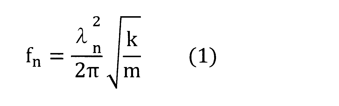
 また支持部15が片端固定の場合は、λ1は1.875、λ2は4.694であるから式(2)から、(kh/kp)>39.3となる。よって、支持部15が片端固定の場合は鉛直方向の剛性と前記水平方向の剛性の値の比が40以上であることが好ましい。
In Expression (2), k h represents the horizontal rigidity, and k p represents the vertical rigidity. Here, when the support portion 15 is fixed at both ends, λ 1 (primary) is 4.730 and λ 2 (secondary) is 7.853 (see Mechanical Engineering Handbook (edited by the Japan Society for Mechanical Engineering)). Therefore, in order that the primary vibration mode in the horizontal direction becomes larger than the secondary vibration mode in the vertical direction when the support portion 15 is fixed at both ends, (k h / k p )> 7.6 is obtained from the equation (2). It is preferable that the ratio between the vertical stiffness and the horizontal stiffness is 8 or more.
In the case supporting portion 15 of one end fixed, lambda 1 is 1.875, lambda 2 from the equation (2) since it is 4.694, and (k h / k p)> 39.3. Therefore, when the support portion 15 is fixed at one end, it is preferable that the ratio of the rigidity value in the vertical direction and the rigidity value in the horizontal direction is 40 or more.
 なお、本実施形態において、支持部15の「両端」とは、振動吸収ユニット14の長軸(平面形状において長さが最も長い部分)に位置する支持部の両方の端部のことをいい、支持部15の「片端」とは、振動吸収ユニット14の長軸に位置する支持部の片方の端部のことをいう。 In the present embodiment, “both ends” of the support portion 15 refers to both ends of the support portion located on the long axis of the vibration absorbing unit 14 (the longest portion in the planar shape), “One end” of the support portion 15 refers to one end portion of the support portion located on the long axis of the vibration absorbing unit 14.
 また、支持部15の中間位置には、低剛性領域の一例としての薄肉部19が設けられている。薄肉部19は、図4,図6に示すように、支持部15の中間位置に設けられた溝であり、当該部分が曲がりやすく構成されている。なお、低剛性領域は、薄肉部に変えて折り目をつけて構成することもできる。 Further, a thin portion 19 as an example of a low rigidity region is provided at an intermediate position of the support portion 15. As shown in FIGS. 4 and 6, the thin portion 19 is a groove provided at an intermediate position of the support portion 15, and the portion is configured to be easily bent. Note that the low-rigidity region can be formed by forming a crease instead of a thin-walled portion.
 支持部15の薄肉部19を挟んで両側の領域15a,15bには、それぞれ重量部16(16a,16b)が設けられている。重量部16(16a,16b)は略円筒形形状の錘であり、互いに重量が異なっている。 The weight portions 16 (16a, 16b) are provided in the regions 15a, 15b on both sides of the thin portion 19 of the support portion 15, respectively. The weight portions 16 (16a, 16b) are substantially cylindrical weights, and have different weights.
 薄肉部19を挟んで異なる質量の重量部16a,16bが設けられていることにより、振動吸収ユニット14が異なる複数の振動態様が発生しやすくなり、それぞれの態様に応じた衝撃に起因する振動を抑えることができる。 Since the weight portions 16a and 16b having different masses are provided across the thin-walled portion 19, the vibration absorbing unit 14 is likely to generate a plurality of different vibration modes, and vibration caused by an impact corresponding to each mode is generated. Can be suppressed.
 また、本実施形態では、支持部15の鉛直方向の剛性k p[N/m]および重量部16の質量m[kg]が以下の範囲に設定されている。
0.1≦kp≦2000
0.001≦m≦0.030
支持部15の鉛直方向の剛性khと重量部16の質量mをこの範囲に設定することにより、一般的な大きさの運動靴のソール踵部分に設けることができる収納空間に収まる振動吸収ユニット14とすることができる。
In the present embodiment, the vertical rigidity k p [N / m] of the support portion 15 and the mass m [kg] of the weight portion 16 are set in the following ranges.
0.1 ≦ k p ≦ 2000
0.001 ≦ m ≦ 0.030
By setting the vertical stiffness k h of the support portion 15 and the mass m of the weight portion 16 within this range, the vibration absorbing unit fits in a storage space that can be provided in the sole heel portion of a general size athletic shoe. 14 can be used.
 ここで、鉛直方向の剛性khとは振動吸収ユニットの重心をバネばかりで押して測定したときの値である。また、重量部16の質量mは振動吸収ユニットのうち支持部15の固定部分を除いた部分の質量である。なお、支持部15の固定部分とは、支持部15がソール2に接触している部分のことをいう。 Here, the vertical stiffness k h is a value measured by pushing the center of gravity of the vibration absorbing unit with a spring alone. Further, the mass m of the weight portion 16 is the mass of the portion of the vibration absorbing unit excluding the fixed portion of the support portion 15. The fixed portion of the support portion 15 is a portion where the support portion 15 is in contact with the sole 2.
 本実施形態では、重量部16a,16bは、支持部15と別部材で構成され、支持部15の所定位置に脱着自在に取り付けられる。図5の例では、重量部16a,16bは主にビス20と受け部21の2つの部材からなる。より具体的には、支持部15の上面側に位置する雄ねじとしてのビス20と支持部15の下面側に位置する雌ねじとしての受け部21とが間に支持部を挟んだ状態で互いにねじ止め固定されている。重量部16をこの分離可能な2以上の部材で形成すれば、ビス20または受け部21のどちらかを違う重さのものに交換することができ、例えば、抑えたい振動数により適した重さの重量部16に交換するといったことが可能となり、ひいては振動吸収ユニット14の設計自由度が向上する。重量部16を分離可能な2以上の部材で形成する他の例として、例えば、凸状の突起部とそれがはめ込まれる凹部を有する受け部とからなるはめ込み構造の重量部16などがあげられる。 In the present embodiment, the weight portions 16a and 16b are configured as separate members from the support portion 15, and are detachably attached to predetermined positions of the support portion 15. In the example of FIG. 5, the weight portions 16 a and 16 b are mainly composed of two members, a screw 20 and a receiving portion 21. More specifically, the screw 20 as a male screw located on the upper surface side of the support portion 15 and the receiving portion 21 as a female screw located on the lower surface side of the support portion 15 are screwed together with the support portion sandwiched therebetween. It is fixed. If the weight portion 16 is formed of two or more separable members, either the screw 20 or the receiving portion 21 can be replaced with one having a different weight, for example, a weight suitable for the frequency to be suppressed. Therefore, the degree of freedom in designing the vibration absorbing unit 14 is improved. As another example of forming the weight portion 16 with two or more separable members, for example, a weight portion 16 having a fitting structure including a protruding protrusion and a receiving portion having a recess into which the protruding portion is fitted can be cited.
 また重量部16の支持部15への固定方法としては、上記のように2つの部材同士で支持部15を挟む方法以外にも、接着剤や熱融着といった方法を採用することもできる。また、支持部15と重量部とを同一材料により一体的に構成することもでき、例えば、支持部の一部分を肉厚に構成することで、当該部分を重量部として機能させてもよい。 Further, as a method for fixing the weight portion 16 to the support portion 15, a method such as an adhesive or heat fusion can be employed in addition to the method of sandwiching the support portion 15 between two members as described above. Moreover, the support part 15 and a weight part can also be integrally comprised by the same material, for example, you may make the said part function as a weight part by comprising a part of support part thickly.
 なお、図9に示すように、支持部15及び重量部16は、ミッドソール4と一体に構成することもできる。図9の例では、支持部15は、下側ミッドソール4bと一体に構成されており、下側ミッドソール4bが下側に開口する凹孔10bの天面が支持部15として機能する。また、当該支持部15の一部分の厚み寸法を大きく構成し、当該部分を重量部として機能させることができる。このように構成することにより、支持部及び重量部をソールと一体的に形成できるため、生産効率を高くすることができる。 In addition, as shown in FIG. 9, the support portion 15 and the weight portion 16 can be configured integrally with the midsole 4. In the example of FIG. 9, the support portion 15 is configured integrally with the lower midsole 4 b, and the top surface of the recessed hole 10 b that opens to the lower side of the lower midsole 4 b functions as the support portion 15. Moreover, the thickness dimension of a part of the support part 15 can be configured to be large, and the part can function as a weight part. By comprising in this way, since a support part and a weight part can be integrally formed with a sole, production efficiency can be made high.
 本実施形態においては、支持部の材料の損失正接に着目し、不快の要因となる振動が身体に伝達するのを有効に抑え、足の着地時から次の着地時までの間に重量部の振動が徐々に小さくなるような材料を採用するために、支持部15は樹脂により作成されている。具体的な損失正接tanδの値は、0.01以上とすることが好ましい。 In this embodiment, paying attention to the loss tangent of the material of the support part, it is possible to effectively suppress the transmission of vibrations that cause discomfort to the body, and the weight of the weight part between the landing of the foot and the next landing In order to employ a material that gradually reduces vibration, the support portion 15 is made of resin. The specific value of loss tangent tan δ is preferably 0.01 or more.
 換言すれば、損失正接tanδの値は、0.01以上とすることで、着地時に生じたエネルギーの多くが次の着地時までに重量部16の振動によって消費されることとなる。そして次の着地時には重量部16が再び大きく振動することが可能となり、衝撃によるエネルギーの多くを吸収することができる。 In other words, by setting the value of the loss tangent tan δ to 0.01 or more, much of the energy generated at the time of landing is consumed by the vibration of the weight portion 16 until the next landing. At the time of the next landing, the weight portion 16 can vibrate greatly again, and much of the energy due to the impact can be absorbed.
 緩衝性を効率よく発揮するためには、着地時の衝撃とともに振動吸収ユニット14の支持部15が振動して、次の着地時には重量部16の振動が十分に減衰していることが求められる。支持部15自身の振動を減衰させることで、次の着地時にも振動が発散することなく、着地時の衝撃を繰り返し緩衝できる。 In order to efficiently exhibit the buffering property, it is required that the support portion 15 of the vibration absorbing unit 14 vibrates with the impact at the time of landing, and the vibration of the weight portion 16 is sufficiently attenuated at the next landing. By attenuating the vibration of the support portion 15 itself, the impact at the time of landing can be buffered repeatedly without the vibration radiating at the time of the next landing.
 重量部16の振動振幅が63%(1/e)減衰されるときの時定数τ[秒]はτ= 2/(ωn tanδ)で表される。ここで、ωn[rad/s]は支持部15の鉛直方向1次の固有振動数、tanδは25℃、50Hzの条件下での損失正接tanδである。 The time constant τ [seconds] when the vibration amplitude of the weight part 16 is attenuated by 63% (1 / e) is represented by τ = 2 / (ωn tan δ). Here, ωn [rad / s] is the natural frequency in the vertical direction of the support portion 15, and tan δ is the loss tangent tan δ under the conditions of 25 ° C. and 50 Hz.
 着地時から再び着地するまでの時間が0.6秒(一般ランナーの平均値)程度であることを考慮すると、τ<0.6となり、この関係を満たすとき、理論上、振動が発散することなく、着地時の衝撃を繰り返し緩衝できることとなる。 Considering that the time from landing to landing again is about 0.6 seconds (average value of general runners), τ <0.6, and when this relationship is satisfied, the vibration should diverge theoretically. In addition, the impact at the time of landing can be buffered repeatedly.
 非特許文献1によれば、人体が不快に感じる胸部の共振周波数は50-100Hzであるから、これらの周波数を緩衝する条件においては、tanδが0.01を上回るとき、上記関係を満たすこととなる。従って、tanδがこの値より小さい材料は好適とはいえない。本実施形態では支持部16として、例えば、tanδが0.01より大きい樹脂材料を採用している。 According to Non-Patent Document 1, since the resonance frequency of the chest that the human body feels uncomfortable is 50-100 Hz, under the conditions for buffering these frequencies, the above relationship is satisfied when tan δ exceeds 0.01. Become. Therefore, a material having a tan δ smaller than this value is not preferable. In the present embodiment, for example, a resin material having a tan δ greater than 0.01 is employed as the support portion 16.
  なお、本実施形態における損失正接tanδは、動的粘弾性装置(株式会社ユービーエム製 Rheogel-E4000)を用いて、ひずみ0%の状態から±0.025%のひずみを引張または圧力方向に加えて測定したときの値である。 The loss tangent tan δ in this embodiment is obtained by applying a strain of ± 0.025% from the strain of 0% to the tensile or pressure direction using a dynamic viscoelastic device (Rheogel-E4000 manufactured by UBM Co., Ltd.). This is the value when measured.
 なお、振動吸収ユニット14は、例えば図10に示すように、支持部15を帯状に構成し、重量部16を挟むように支持部15両端を固定位置としてもよい。 Note that, in the vibration absorbing unit 14, for example, as illustrated in FIG. 10, the support portion 15 may be configured in a band shape, and both ends of the support portion 15 may be fixed positions so as to sandwich the weight portion 16.
 また、振動吸収ユニット14は、支持部15を1枚の薄板状で構成する必要はなく、例えば図11に示すような構成とすることができる。図11に示す変形例では、支持部15は、ソールの収納空間10の開口周縁に配置される外周縁22と、重量部16を取り付ける重量取付部24と、重量取付部24に向かって放射状に伸びる複数の支持腕23とを備える。重量取付部24には、重量部16が取り付けられる。 Further, the vibration absorbing unit 14 does not need to be configured by the thin plate shape of the support portion 15 and can be configured as shown in FIG. 11, for example. In the modified example shown in FIG. 11, the support portion 15 is radially outward toward the outer peripheral edge 22 disposed at the opening peripheral edge of the sole storage space 10, the weight attaching portion 24 to which the weight portion 16 is attached, and the weight attaching portion 24. And a plurality of extending support arms 23. The weight portion 16 is attached to the weight attachment portion 24.
 この構成により重量部16がその周囲を間欠的に支持されているため、支持部の鉛直方向の剛性が低くなり、鉛直方向への振動が発生しやすくなる。 Since the weight portion 16 is intermittently supported by this configuration, the vertical rigidity of the support portion is reduced, and vibration in the vertical direction is likely to occur.
 なお、図11に示す振動吸収ユニット14は、中央に1つの重量部16を支持する構成であるので、この構成の振動吸収ユニット14を用いる場合は、ソール4に複数の収納空間10を設け、それぞれに重量部の重量が異なる振動吸収ユニット14を配置するようにしてもよい。 Since the vibration absorbing unit 14 shown in FIG. 11 is configured to support one weight portion 16 at the center, when the vibration absorbing unit 14 having this configuration is used, a plurality of storage spaces 10 are provided in the sole 4, You may make it arrange | position the vibration absorption unit 14 from which the weight of a weight part differs in each.
 また、図12の変形例では、中央に設けられた重量取付部24に一体的に設けられた小重量部25を有する。小重量部25は、支持部15の鉛直方向への振動により撚れるように変形し、これにより、支持部15全体の周波数が変動して、幅広い周波数帯での振動が可能となる。 In addition, in the modified example of FIG. 12, there is a small weight portion 25 provided integrally with the weight attaching portion 24 provided at the center. The small weight portion 25 is deformed so as to be twisted by the vibration of the support portion 15 in the vertical direction, whereby the frequency of the entire support portion 15 is changed, and vibration in a wide frequency band is possible.
 本第1実施形態にかかる運動靴によれば、支持部15の鉛直方向の剛性が水平方向の剛性よりも小さいことから、重量部16が主として鉛直方向に大きく振動することとなる。この振動により走行時あるいは歩行時における足の着地時の衝撃によるエネルギーが効率よく重量部の振動エネルギーに変換され取り除かれる。このため、着地により衝撃を効率よく除去することができ、使用者に伝播する振動を抑えることができる。 According to the athletic shoe according to the first embodiment, since the vertical rigidity of the support portion 15 is smaller than the horizontal rigidity, the weight portion 16 mainly vibrates largely in the vertical direction. By this vibration, the energy caused by the impact at the time of landing of the foot during running or walking is efficiently converted to the vibration energy of the weight part and removed. For this reason, an impact can be efficiently removed by landing, and vibration propagating to the user can be suppressed.
(第2実施形態)
 図13は、本発明の第2実施形態にかかる運動靴のソール部分の構成を模式的に示す分解斜視図である。本実施形態では、ソール2は、土踏まずの部分に配置されるシャンク26を備えている。シャンクは、土踏まずのアーチ状の形状を維持するためにソールに用いられる部材であり、土踏まずの部分を下側からサポートし、また、体重でアーチがつぶれない程度の硬さを有している。シャンクを構成する材料は、例えば、金属や合成樹脂などを用いることができる。
(Second embodiment)
FIG. 13 is an exploded perspective view schematically showing the configuration of the sole portion of the athletic shoe according to the second embodiment of the present invention. In the present embodiment, the sole 2 includes a shank 26 disposed on the arch portion. The shank is a member used for the sole to maintain the arch-like shape of the arch, supports the arch portion from below, and has a hardness that does not cause the arch to collapse with weight. As a material constituting the shank, for example, a metal or a synthetic resin can be used.
 シャンク26の後側には、踵部8のみに設けられた下側ミッドソール4bが位置している。下側ミッドソール4bは、上側ミッドソール4aと積層するように接続され、ミッドソール4を構成する。 On the rear side of the shank 26, a lower midsole 4b provided only in the buttocks 8 is located. The lower midsole 4b is connected so as to be laminated with the upper midsole 4a, and constitutes the midsole 4.
 ミッドソール4の踵部8には、振動吸収ユニット14を収納するための収納空間10が設けられる。収納空間10は、ソール2の踵部8に設けられる靴底面に開口した孔であり、ミッドソール4をくり抜いたような形状に構成されている。具体的には、下側ミッドソール4bの踵部8に貫通孔を設け、上側ミッドソール4aに有底孔を設け、両者を積層することで、所定の寸法に構成された収納空間10が形成される。 A storage space 10 for storing the vibration absorbing unit 14 is provided in the collar portion 8 of the midsole 4. The storage space 10 is a hole opened in the bottom of the shoe provided in the heel part 8 of the sole 2, and is configured in such a shape that the midsole 4 is cut out. Specifically, a through-hole is provided in the flange portion 8 of the lower midsole 4b, a bottomed hole is provided in the upper midsole 4a, and the two are stacked to form a storage space 10 having a predetermined size. Is done.
 図13に示すように、シャンク26の後方には、踵側に伸びる舌片27が設けられている。当該舌片27は、振動吸収ユニット14の支持部15として機能するものであり、中間部分より後方側が収納空間10内に位置すると共に、端部分が収納空間10後方側よりも突出するようになっている。このような構造により、支持部15は片方の端部のみがシャンク26に固定されていることになる。 As shown in FIG. 13, a tongue piece 27 extending toward the heel side is provided behind the shank 26. The tongue piece 27 functions as the support portion 15 of the vibration absorbing unit 14, and the rear side of the intermediate portion is located in the storage space 10 and the end portion protrudes from the rear side of the storage space 10. ing. With such a structure, only one end of the support portion 15 is fixed to the shank 26.
 また、舌片27の中間部分には、低剛性領域の一例としての薄肉部19が設けられる。薄肉部19を挟んで両側には、それぞれ重量部16(16a,16b)が設けられている。重量部16(16a,16b)は略円筒形形状の錘であり、互いに重量が異なっている。 Further, a thin portion 19 as an example of a low rigidity region is provided in the intermediate portion of the tongue piece 27. Weight portions 16 (16a, 16b) are provided on both sides of the thin portion 19, respectively. The weight portions 16 (16a, 16b) are substantially cylindrical weights, and have different weights.
 本実施形態では、重量部16a,16bは、支持部15と別部材で構成され、支持部15の下面側に接着固定されている。 In the present embodiment, the weight portions 16a and 16b are configured as separate members from the support portion 15, and are bonded and fixed to the lower surface side of the support portion 15.
 この構成により、舌片27の収納空間10内に位置する部分が振動吸収ユニット14の支持部15として機能し、着地による衝撃を受けた際に、所定の周波数で振動する。特に支持部15の片方の端部のみが固定された振動吸収ユニットとなることから、例えば、同一材料からなる両端固定の支持部15の場合と比べ、鉛直方向の剛性が低く、より振動しやすくなる。また、薄肉部19を挟んで異なる質量の重量部16a,16bが設けられていることにより、振動吸収ユニット14が異なる複数の振動態様が発生しやすくなり、それぞれの態様に応じた衝撃に起因する振動を抑えることができる。 With this configuration, the portion of the tongue piece 27 located in the storage space 10 functions as the support portion 15 of the vibration absorbing unit 14, and vibrates at a predetermined frequency when receiving an impact due to landing. Particularly, since only one end of the support portion 15 is fixed, the vibration absorbing unit is fixed. For example, compared to the case of the support portion 15 made of the same material and fixed at both ends, the rigidity in the vertical direction is lower and the vibration is more easily generated. Become. In addition, since the weight portions 16a and 16b having different masses are provided across the thin-walled portion 19, the vibration absorbing unit 14 is likely to generate a plurality of different vibration modes, and is caused by an impact corresponding to each mode. Vibration can be suppressed.
(第3実施形態)
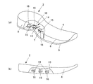
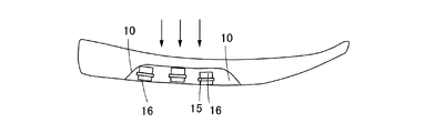
 図14は、本発明の第3実施形態にかかる運動靴(左足用)のソール部分の構成を模式的に示す図であり、(a)は部分断面斜視図、(b)は側面図である。図15は、図14のソール部分に荷重がかかった状態を示す側面図である。本実施形態では、ソール2は、振動吸収ユニット14を収納するための収納空間10が中足部7に設けられている。また、振動吸収ユニット14は、異なる周波数で振動する3つの支持部15が独立した構成を有しており、また、支持部15は、ソール2の幅方向に沿った端部側で支持されている。
(Third embodiment)
FIGS. 14A and 14B are views schematically showing a configuration of a sole portion of an athletic shoe (for left foot) according to a third embodiment of the present invention, wherein FIG. 14A is a partial sectional perspective view, and FIG. 14B is a side view. . FIG. 15 is a side view showing a state in which a load is applied to the sole portion of FIG. In the present embodiment, the sole 2 is provided with a storage space 10 in the middle foot 7 for storing the vibration absorbing unit 14. Further, the vibration absorption unit 14 has a configuration in which three support portions 15 that vibrate at different frequencies are independent, and the support portion 15 is supported on the end side along the width direction of the sole 2. Yes.
 ソール2に設けられた収納空間10は、上記のように、土踏まず部分を含む中足部7に設けられる。収納空間10の高さ寸法は、後述するように中足部7を下支えする重量部16の高さ方向寸法に応じて決定すればよい。 The storage space 10 provided in the sole 2 is provided in the middle foot portion 7 including the arch portion as described above. What is necessary is just to determine the height dimension of the storage space 10 according to the height direction dimension of the weight part 16 which supports the middle leg part 7 so that it may mention later.
 振動吸収ユニット14は、上記のように独立した3つの支持部15が幅方向に位置する端部で支持され、前後方向に略平行に並ぶように構成されている。また、重量部16は、土踏まず部分に位置するように端部側に偏って配置される。それぞれの重量部16は互いに質量が異なっており、支持部15の振動する周波数が異なるようになっている。 As described above, the vibration absorbing unit 14 is configured such that the three independent support portions 15 are supported by the end portions positioned in the width direction, and are arranged substantially in parallel in the front-rear direction. In addition, the weight portion 16 is arranged so as to be biased toward the end portion so as to be positioned on the arch portion. The respective weight parts 16 have different masses, and the frequency at which the support part 15 vibrates is different.
 本実施形態にかかる運動靴は、着地時の踵接地の衝撃により、支持部15がそれぞれ異なる態様で振動し、人体に伝播する振動を除去することができる。また、振動吸収ユニット14を収納するための収納空間10が土踏まずを含む中足部7に設けられているため、着地時において上からの荷重が中足部7に加わることで収納空間10が変形する。このとき、図15に示すように、土踏まず部分に位置する重量部16が、土踏まず部分の中足部7の変形を下支えし、土踏まず部分のアーチが過度に変形することを防止することができる。 In the sports shoes according to the present embodiment, the support portions 15 vibrate in different modes due to the impact of the ground contact at the time of landing, and vibrations propagating to the human body can be removed. Further, since the storage space 10 for storing the vibration absorbing unit 14 is provided in the middle foot portion 7 including the arch, the storage space 10 is deformed by applying a load from above to the middle foot portion 7 at the time of landing. To do. At this time, as shown in FIG. 15, the weight portion 16 located in the arch portion supports the deformation of the middle foot portion 7 of the arch portion, and it is possible to prevent the arch of the arch portion from being excessively deformed.
 なお、本実施形態にかかる運動靴は、図16に示す変形例のように、中足部7の幅を踵部8よりも大きく構成し、中足部7内に収納する振動吸収ユニット14を大きく構成することもできる。また、踵部8には、着地衝撃を吸収するための緩衝部材5cが設けられている。 In addition, the athletic shoe according to the present embodiment includes a vibration absorbing unit 14 configured such that the width of the middle foot portion 7 is larger than that of the heel portion 8 and accommodated in the middle foot portion 7 as in the modification shown in FIG. It can also be configured large. Further, the flange portion 8 is provided with a buffer member 5c for absorbing a landing impact.
 図16に示す変形例では、振動吸収ユニット14は、支持部15を斜めに配置することで長く構成されている。また、支持部15の両端は、中足部7の形状に沿うように円弧状に構成して、中足部7のソール内に配置する。 In the modification shown in FIG. 16, the vibration absorbing unit 14 is configured to be long by arranging the support portions 15 obliquely. Further, both ends of the support portion 15 are formed in an arc shape so as to follow the shape of the midfoot portion 7 and are disposed in the sole of the midfoot portion 7.
(第4実施形態)
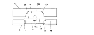
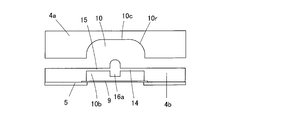
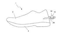
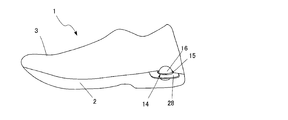
 図17は、本発明の第4実施形態にかかる運動靴の構成を模式的に示す側面図である。本実施形態にかかる運動靴1は、振動吸収ユニット14がソール2の内部ではなく、アッパー側に取り付けられている点において上述の実施形態とは異なる。具体的には、振動吸収ユニット14は、アッパー3の踵部分に固定された取り付けベース24を介して後方に突出した位置に取り付けられている。
(Fourth embodiment)
FIG. 17: is a side view which shows typically the structure of the athletic shoe concerning 4th Embodiment of this invention. The athletic shoe 1 according to the present embodiment is different from the above-described embodiment in that the vibration absorbing unit 14 is attached not to the inside of the sole 2 but to the upper side. Specifically, the vibration absorbing unit 14 is attached to a position protruding rearward via an attachment base 24 fixed to the flange portion of the upper 3.
 図18は、第4実施形態にかかる運動靴に用いられる振動吸収ユニットの取り付け構成を模式的に示す部分拡大図である。振動吸収ユニット14は、アッパー3の一部としてアッパー3の踵部分に固定されている取り付けベース28に固定されている。取り付けベース28は板状の部材であり、一つの辺が、アッパー3の踵部分の形状に沿うように円弧状に構成された取り付け辺29となっている。また、厚み方向に貫通した保持孔30を備えており、当該保持孔30に、振動吸収ユニット14を収容する。 FIG. 18 is a partially enlarged view schematically showing the mounting configuration of the vibration absorbing unit used in the athletic shoe according to the fourth embodiment. The vibration absorbing unit 14 is fixed to a mounting base 28 that is fixed to a flange portion of the upper 3 as a part of the upper 3. The mounting base 28 is a plate-like member, and one side is a mounting side 29 configured in an arc shape so as to follow the shape of the flange portion of the upper 3. Further, a holding hole 30 penetrating in the thickness direction is provided, and the vibration absorbing unit 14 is accommodated in the holding hole 30.
 保持孔30は、重量部16よりも大きく開口した円形の貫通孔であり、周縁に支持部15の重量部16と接しない外側端部15aを有する。支持部15は、本実施形態では、4つの支持腕で構成されており、内側端部に球形の重量部16が固定される。これにより、保持孔30の内側に重量部が、鉛直方向に振動可能に配置される。なお、支持腕は4つに限らず重量部16を振動させることができれば何本でもよい。また、保持孔30と略同一形状の支持部15を保持孔30を埋めるように配置して、支持部15の外縁全体が取り付けベース28に接続されるようにしてもよい。走行時あるいは歩行時における足の着地時の衝撃によるエネルギーは、重量部の振動エネルギーに変換され、身体に伝播する振動を除去することができる。また、振動吸収ユニット14がアッパーの外部に設けられているため、ソール2の内部に配置する場合に比べ、取り付けスペースの制約がなくなり、重量部16を大きくしやすく、ソール2の機能を阻害することがない。なお、重量部16の質量mは振動吸収ユニットのうち支持部15の固定部分を除いた部分の質量であり、支持部15の固定部分とは、支持部15が取り付けベース28に接触している部分のことをいう。 The holding hole 30 is a circular through hole that is opened larger than the weight portion 16, and has an outer end portion 15 a that does not contact the weight portion 16 of the support portion 15 at the periphery. In the present embodiment, the support portion 15 includes four support arms, and a spherical weight portion 16 is fixed to the inner end portion. Thereby, a weight part is arrange | positioned inside the holding hole 30 so that a vibration is possible to a perpendicular direction. The number of support arms is not limited to four, and any number may be used as long as the weight portion 16 can be vibrated. Further, the support portion 15 having substantially the same shape as the holding hole 30 may be arranged so as to fill the holding hole 30, and the entire outer edge of the support portion 15 may be connected to the mounting base 28. The energy generated by the impact at the time of landing of the foot during running or walking is converted into the vibration energy of the weight part, and the vibration propagating to the body can be removed. In addition, since the vibration absorbing unit 14 is provided outside the upper, there is no restriction on the installation space, compared with the case where the vibration absorbing unit 14 is disposed inside the sole 2, the weight portion 16 is easily enlarged, and the function of the sole 2 is hindered. There is nothing. The mass m of the weight portion 16 is the mass of the vibration absorbing unit excluding the fixed portion of the support portion 15, and the support portion 15 is in contact with the mounting base 28 with the fixed portion of the support portion 15. Refers to the part.
(第5実施形態)
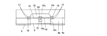
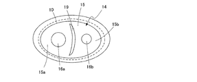
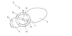
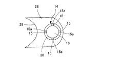
 図19は、本発明の第5実施形態にかかる運動靴の構成を模式的に示す側面図である。図20は、第5実施形態にかかる運動靴の構成を模式的に示す平面図である。本実施形態にかかる運動靴1は、振動吸収ユニット14がソール2の内部ではなく、アッパー3の外側へ突出して設けられている点において第4実施形態にかかる運動靴と共通するが、振動吸収ユニット14を取り付ける取り付けベース28の取り付け位置が異なる。取り付けベース28は、アッパー3とソール2の境界部分に、両側方に突出するように設けられており、第4実施形態とほぼ共通する構成振動吸収ユニット14を保持孔30内に収納する。
(Fifth embodiment)
FIG. 19 is a side view schematically showing the configuration of the athletic shoe according to the fifth embodiment of the present invention. FIG. 20 is a plan view schematically showing the configuration of the athletic shoe according to the fifth embodiment. The athletic shoe 1 according to the present embodiment is common to the athletic shoe according to the fourth embodiment in that the vibration absorbing unit 14 is provided not on the inside of the sole 2 but on the outside of the upper 3. The attachment position of the attachment base 28 to which the unit 14 is attached is different. The mounting base 28 is provided at the boundary portion between the upper 3 and the sole 2 so as to protrude on both sides, and houses the structural vibration absorbing unit 14 that is substantially common to the fourth embodiment in the holding hole 30.
 本実施形態によれば、振動吸収ユニット14がアッパーの外部に設けられているため、取り付けスペースの制約がなくなり、重量部16を大きくしやすく、ソール2の機能を阻害することがない。また、振動吸収ユニットの重心と踵接地時の荷重中心と足長方向におけるずれが小さいため、鉛直方向に振動しやすく大きな振動吸収効果が期待できる。 According to the present embodiment, since the vibration absorbing unit 14 is provided outside the upper, there is no restriction on the installation space, the weight portion 16 is easily enlarged, and the function of the sole 2 is not hindered. In addition, since the deviation in the foot length direction from the center of gravity of the vibration absorbing unit, the load center at the time of heel contact and the foot length direction is small, a large vibration absorbing effect can be expected.
 なお、本発明は上記各実施形態に限定されるものではなく、その他種々の態様で実施できる。例えば、重量部16の形状は、円柱形や球形に限定されるものではなく、角柱や円盤形状等に構成されていてもよい。 Note that the present invention is not limited to the above-described embodiments, and can be implemented in various other modes. For example, the shape of the weight portion 16 is not limited to a cylindrical shape or a spherical shape, and may be configured in a prismatic shape, a disc shape, or the like.
 なお、上記様々な実施形態のうちの任意の実施形態を適宜組み合わせることにより、それぞれの有する効果を奏するようにすることができる。
 本発明は、添付図面を参照しながら好ましい実施形態に関連して充分に記載されているが、この技術の熟練した人々にとっては種々の変形や修正は明白である。そのような変形や修正は、添付した請求の範囲による本発明の範囲から外れない限りにおいて、その中に含まれると理解されるべきである。
It is to be noted that, by appropriately combining arbitrary embodiments of the various embodiments described above, the effects possessed by them can be produced.
Although the present invention has been fully described in connection with preferred embodiments with reference to the accompanying drawings, various variations and modifications will be apparent to those skilled in the art. Such changes and modifications are to be understood as being included therein, so long as they do not depart from the scope of the present invention according to the appended claims.
 1    運動靴
 2    ソール
 3    アッパー
 4    ミッドソール
 4a   上側ミッドソール
 4b   下側ミッドソール
 5    アウターソール
 5c   緩衝部材
 6    前足部
 7    中足部
 8    踵部
 9    保護板
10    収納空間
10b   凹孔
10c   天面
10r   角部
11    上被部
12    インナーソール
13    インソール
14    振動吸収ユニット
15    支持部
15a   支持部外側端部16,16a,16b    重量部
17    位置決め凹部
18    接着剤
19    薄肉部
20    ビス
21    受け部
22    外周縁
23    支持腕
24    重量取付部
25    小重量部
26    シャンク
27    舌片
28    取り付けベース
29    取り付け辺
30    保持孔
DESCRIPTION OF SYMBOLS 1 Athletic shoes 2 Sole 3 Upper 4 Midsole 4a Upper midsole 4b Lower midsole 5 Outer sole 5c Buffer member 6 Forefoot part 7 Middle foot part 8 Grow part 9 Protection board 10 Storage space 10b Recessed hole 10c Top surface 10r Corner part DESCRIPTION OF SYMBOLS 11 Upper cover part 12 Inner sole 13 Insole 14 Vibration absorption unit 15 Support part 15a Support part outer side edge part 16, 16a, 16b Weight part 17 Positioning recessed part 18 Adhesive 19 Thin part 20 Screw 21 Receiving part 22 Outer peripheral edge 23 Support arm 24 Weight mounting portion 25 Small weight portion 26 Shank 27 Tongue piece 28 Mounting base 29 Mounting side 30 Holding hole

Claims (26)

  1.  ソールと、前記ソールの上側に配置されるアッパーと、前記ソールおよび前記アッパーの少なくとも一方に固定されるとともに着地による衝撃で発生する振動を吸収する振動吸収ユニットとを備え、
     前記振動吸収ユニットは、鉛直方向の剛性が水平方向の剛性よりも小さく構成され可撓性を有する板状の支持部と、前記支持部に設けられた少なくとも1つの重量部とを備え、
     前記支持部は、前記重量部の周囲の少なくとも一部を取り囲み、前記ソール又はアッパーに対して固定されている、履物。
    A sole, an upper disposed on the upper side of the sole, and a vibration absorbing unit that is fixed to at least one of the sole and the upper and absorbs vibration generated by an impact caused by landing,
    The vibration absorption unit includes a plate-like support portion that has a vertical rigidity smaller than a horizontal rigidity and has flexibility, and at least one weight portion provided in the support portion,
    The footwear surrounds at least a part of the periphery of the weight portion and is fixed to the sole or the upper.
  2.  ソールと、前記ソールの上側に配置されるアッパーと、前記ソールおよび前記アッパーの少なくとも一方に取り付けられる振動吸収ユニットとを備え、
     前記振動吸収ユニットは、着地時の衝撃によって撓む板状の支持部および前記支持部に取り付けられた重量部を備え、
     前記支持部は、鉛直方向の剛性が水平方向の剛性よりも小さく構成されるとともに、損失正接が25℃、50Hzの条件下で0.01以上である材料からなる、履物。
    A sole, an upper disposed above the sole, and a vibration absorbing unit attached to at least one of the sole and the upper,
    The vibration absorption unit includes a plate-like support portion that is bent by an impact at the time of landing and a weight portion attached to the support portion,
    The said support part is footwear which consists of a material which the rigidity of a perpendicular direction is comprised smaller than the rigidity of a horizontal direction, and loss tangent is 0.01 or more on conditions of 25 degreeC and 50 Hz.
  3.  前記ソールは踵部分に設けられた収納空間を有し、
    前記振動吸収ユニットは、前記収納空間内に配置されている、請求項1又は2に記載の履物。
    The sole has a storage space provided in the heel portion,
    The footwear according to claim 1, wherein the vibration absorbing unit is disposed in the storage space.
  4.  前記支持部の外縁全体が前記ソール又はアッパーへ固定されている、請求項1又は2に記載の履物。 The footwear according to claim 1 or 2, wherein the entire outer edge of the support portion is fixed to the sole or the upper.
  5.  前記振動吸収ユニットは、前記支持部の外縁が間欠的に前記ソール又はアッパーへ固定されている、請求項1又は2に記載の履物。 The footwear according to claim 1 or 2, wherein in the vibration absorbing unit, an outer edge of the support portion is intermittently fixed to the sole or the upper.
  6.  前記収納空間は、前記ソールの下面側に開口するように構成されている、請求項3に記載の履物。 The footwear according to claim 3, wherein the storage space is configured to open to a lower surface side of the sole.
  7.  前記収納空間の開口は、前記保護板により閉塞されている、請求項3に記載の履物。 The footwear according to claim 3, wherein the opening of the storage space is closed by the protective plate.
  8.  前記保護板は半透明である請求項7に記載の履物。 The footwear according to claim 7, wherein the protective plate is translucent.
  9.  前記支持部は、全周にわたって前記収納空間の側壁に支持されている、請求項3に記載の履物。 The footwear according to claim 3, wherein the support portion is supported on a side wall of the storage space over the entire circumference.
  10.  前記振動吸収ユニットは、重量の異なる複数の前記重量部を有する、請求項3に記載の履物。 The footwear according to claim 3, wherein the vibration absorption unit has a plurality of the weight parts having different weights.
  11.  前記支持部は中央部分に周囲よりも剛性の低い低剛性領域を有し、前記複数の重量部は、前記低剛性領域を挟んで前記支持部の両側に取り付けられる請求項10に記載の履物。 The footwear according to claim 10, wherein the support portion has a low-rigidity region whose rigidity is lower than that of the periphery at a central portion, and the plurality of weight portions are attached to both sides of the support portion with the low-rigidity region being sandwiched therebetween.
  12.  前記低剛性領域は、前記支持部に設けられた薄肉部で構成されている請求項11に記載の履物。 The footwear according to claim 11, wherein the low-rigidity region is formed of a thin portion provided in the support portion.
  13.  前記振動吸収ユニットは、前記支持部と重量部が同一材料により一体に構成され、前記重量部は前記支持部よりも肉厚に構成されている、請求項1又は2に記載の履物。 The footwear according to claim 1 or 2, wherein in the vibration absorbing unit, the support portion and the weight portion are integrally formed of the same material, and the weight portion is configured to be thicker than the support portion.
  14.  前記ソールは、上側ソールと前記上側ソールの下に配置される下側ソールとを含み、前記支持部は、前記上側ソールと前記下側ソールとの間に挟持されるように支持される、請求項3に記載の履物。 The sole includes an upper sole and a lower sole disposed below the upper sole, and the support portion is supported so as to be sandwiched between the upper sole and the lower sole. Item 3. Footwear.
  15.  前記ソールは、上側ソールと前記上側ソールの下に配置される下側ソールとを含み、前記支持部は、前記上側ソール又は前記下側ソールと同一材料により一体に構成されている、請求項3に記載の履物。 The sole includes an upper sole and a lower sole disposed below the upper sole, and the support portion is integrally formed of the same material as the upper sole or the lower sole. Footwear described in.
  16.  前記ソールは、土踏まずの部分に配置されるシャンクを有し、前記支持部は、当該シャンクから踵側に伸びる舌片で構成されている、請求項3に記載の履物。 The footwear according to claim 3, wherein the sole includes a shank disposed on an arch portion, and the support portion is formed of a tongue piece extending from the shank toward the heel side.
  17.  前記ソールは、中足部の幅が踵部分の幅よりも広く形成されており、前記振動吸収ユニットは、前記ソールの中足部に設けられた収納空間内に配置されている、請求項1又は2に記載の履物。 The sole is formed such that a width of a middle foot portion is wider than a width of a heel portion, and the vibration absorbing unit is disposed in a storage space provided in the middle foot portion of the sole. Or footwear according to 2.
  18.  前記重量部は、前記土踏まずのアーチ部分に位置するように前記振動吸収ユニットが配置されている、請求項17に記載の履物。 The footwear according to claim 17, wherein the vibration absorbing unit is disposed so that the weight portion is located at an arch portion of the arch.
  19.  前記アッパー又はソールは、前記アッパー又はソールに対して外側へ突出するように配置され、前記振動吸収ユニットを収納する保持孔を有する取り付けベースを備え、
     前記振動吸収ユニットは、前記支持部が前記保持孔の周縁に連結して固定される、請求項1又は2に記載の履物。
    The upper or the sole is provided so as to protrude outward with respect to the upper or the sole, and includes an attachment base having a holding hole for storing the vibration absorbing unit,
    The footwear according to claim 1 or 2, wherein the vibration absorbing unit is fixed by connecting the support portion to a peripheral edge of the holding hole.
  20.  前記取り付けベースは、前記アッパーの踵部分から後方に突出するように設けられている、請求項19に記載の履物。 The footwear according to claim 19, wherein the mounting base is provided so as to protrude rearward from a heel portion of the upper.
  21.  前記取り付けベースは、前記アッパーと前記ソールの内側の境界部分からに突出するように設けられた第1取り付けベースと、前記アッパーと前記ソールの外側の境界部分からに突出するように設けられた第2取り付けベースとを含む請求項19に記載の履物。 The mounting base includes a first mounting base provided to protrude from an inner boundary portion of the upper and the sole, and a first mounting base provided to protrude from an outer boundary portion of the upper and the sole. 20. Footwear according to claim 19, comprising two mounting bases.
  22.  前記支持部の鉛直方向の剛性が0.1から2000N/mの範囲内であり、前記重量部の質量が0.001から0.030kgの範囲内である、請求項1又は2に記載の履物。 The footwear according to claim 1 or 2, wherein a vertical rigidity of the support portion is in a range of 0.1 to 2000 N / m, and a mass of the weight portion is in a range of 0.001 to 0.030 kg. .
  23.  前記支持部は両端が固定されており、前記支持部の鉛直方向の剛性kpと前記水平方向の剛性khの値の比が、(kh/kp)≧8を満たす、請求項1又は2に記載の履物。 The support part is fixed at both ends, and a ratio of a value of a rigidity k p in the vertical direction and a value of the rigidity k h in the horizontal direction of the support part satisfies (k h / k p ) ≧ 8. Or footwear according to 2.
  24.  前記支持部は片方の端部のみが固定されており、前記支持部の鉛直方向の剛性kpと前記水平方向の剛性khの値の比が、(kh/kp)≧40を満たす、請求項1又は2に記載の履物。 Only one end of the support portion is fixed, and the ratio of the vertical stiffness k p and the horizontal stiffness k h of the support portion satisfies (k h / k p ) ≧ 40. The footwear according to claim 1 or 2.
  25. 前記収納空間の天面と側面との角部は丸みを帯びている請求項3に記載の履物。 The footwear according to claim 3, wherein corners between the top surface and the side surface of the storage space are rounded.
  26.  収納空間を有するソールと、前記ソールの上側に配置されるアッパーと、前記収納空間内に収納される振動吸収ユニットとを備え、
     前記振動吸収ユニットは、着地時の衝撃によって撓む板状の支持部及び前記支持部に取り付けられた重量部を備え、
     前記収納空間は、前記振動吸収ユニットの自重による鉛直方向のたわみ量の3倍以上の空間が前記振動吸収ユニットの上下位置するように高さ寸法が設定されている、履物。
    A sole having a storage space, an upper disposed above the sole, and a vibration absorbing unit stored in the storage space;
    The vibration absorbing unit includes a plate-like support portion that is bent by an impact at the time of landing, and a weight portion attached to the support portion,
    The footwear is configured such that the storage space has a height dimension so that a space that is at least three times the amount of vertical deflection caused by the weight of the vibration absorbing unit is positioned above and below the vibration absorbing unit.
PCT/JP2015/086472 2015-12-28 2015-12-28 Footwear WO2017115402A1 (en)

Priority Applications (4)

Application Number Priority Date Filing Date Title
US16/066,643 US11058170B2 (en) 2015-12-28 2015-12-28 Footwear
EP15912068.2A EP3398467B1 (en) 2015-12-28 2015-12-28 Footwear
PCT/JP2015/086472 WO2017115402A1 (en) 2015-12-28 2015-12-28 Footwear
JP2017558804A JP6710704B2 (en) 2015-12-28 2015-12-28 footwear

Applications Claiming Priority (1)

Application Number Priority Date Filing Date Title
PCT/JP2015/086472 WO2017115402A1 (en) 2015-12-28 2015-12-28 Footwear

Publications (1)

Publication Number Publication Date
WO2017115402A1 true WO2017115402A1 (en) 2017-07-06

Family

ID=59224711

Family Applications (1)

Application Number Title Priority Date Filing Date
PCT/JP2015/086472 WO2017115402A1 (en) 2015-12-28 2015-12-28 Footwear

Country Status (4)

Country Link
US (1) US11058170B2 (en)
EP (1) EP3398467B1 (en)
JP (1) JP6710704B2 (en)
WO (1) WO2017115402A1 (en)

Cited By (1)

* Cited by examiner, † Cited by third party
Publication number Priority date Publication date Assignee Title
CN109430998A (en) * 2018-11-14 2019-03-08 浙江工贸职业技术学院 A kind of cooling shock-absorbing sport shoes

Families Citing this family (1)

* Cited by examiner, † Cited by third party
Publication number Priority date Publication date Assignee Title
US11399594B2 (en) * 2013-05-07 2022-08-02 Danielle M Kassatly Footwear auxiliaries for synchronously toning leg muscles in order to straighten back posture

Citations (8)

* Cited by examiner, † Cited by third party
Publication number Priority date Publication date Assignee Title
JPH01303334A (en) * 1987-10-05 1989-12-07 Asics Corp Damping member
JPH0723804A (en) * 1993-07-13 1995-01-27 Yamaha Corp Sports shoes
JPH07313203A (en) * 1994-05-26 1995-12-05 Toyohiko Nishibe Footwear main sole
JPH09273582A (en) * 1996-04-02 1997-10-21 Bridgestone Corp Shock absorbing member
JPH11506027A (en) * 1995-05-30 1999-06-02 ザ ロックポート カンパニー,インコーポレイテッド Inserts for soles
JP2007530308A (en) * 2003-07-16 2007-11-01 ナイキ・インコーポレーテッド Footwear having a bottom structure incorporating a branched fluid-filled chamber
JP2010525918A (en) * 2007-05-09 2010-07-29 グ キム,ソン Functional footwear
JP5459741B2 (en) * 2009-09-21 2014-04-02 ウェルネスヒルズ、インコーポレイテッド Footwear that generates vibration and vibration device thereof

Family Cites Families (10)

* Cited by examiner, † Cited by third party
Publication number Priority date Publication date Assignee Title
JP2905928B2 (en) 1989-11-30 1999-06-14 株式会社シーゲル Vibration absorber in the sole
US20060157901A1 (en) * 2001-08-27 2006-07-20 Sting Free Company Vibration dampening material and method of making same
US20080066348A1 (en) * 2005-02-07 2008-03-20 Select Sole, Llc Footwear with retractable members
US7234250B2 (en) * 2005-02-07 2007-06-26 Stacy Renee Fogarty Convertible traction shoes
US8008363B2 (en) 2005-05-10 2011-08-30 Asics Corporation Shoe sole component
US8056261B2 (en) * 2007-07-20 2011-11-15 Wolverine World Wide, Inc. Footwear sole construction
US8307572B2 (en) * 2009-09-21 2012-11-13 Nike, Inc. Protective boot
US9210967B2 (en) * 2010-08-13 2015-12-15 Nike, Inc. Sole structure with traction elements
US9009991B2 (en) * 2011-06-23 2015-04-21 Nike, Inc. Article of footwear with a cavity viewing system
CA2822759A1 (en) * 2013-08-05 2015-02-05 Richard Patrick Desmarais Footwear having cushioning between sole and upper

Patent Citations (8)

* Cited by examiner, † Cited by third party
Publication number Priority date Publication date Assignee Title
JPH01303334A (en) * 1987-10-05 1989-12-07 Asics Corp Damping member
JPH0723804A (en) * 1993-07-13 1995-01-27 Yamaha Corp Sports shoes
JPH07313203A (en) * 1994-05-26 1995-12-05 Toyohiko Nishibe Footwear main sole
JPH11506027A (en) * 1995-05-30 1999-06-02 ザ ロックポート カンパニー,インコーポレイテッド Inserts for soles
JPH09273582A (en) * 1996-04-02 1997-10-21 Bridgestone Corp Shock absorbing member
JP2007530308A (en) * 2003-07-16 2007-11-01 ナイキ・インコーポレーテッド Footwear having a bottom structure incorporating a branched fluid-filled chamber
JP2010525918A (en) * 2007-05-09 2010-07-29 グ キム,ソン Functional footwear
JP5459741B2 (en) * 2009-09-21 2014-04-02 ウェルネスヒルズ、インコーポレイテッド Footwear that generates vibration and vibration device thereof

Cited By (2)

* Cited by examiner, † Cited by third party
Publication number Priority date Publication date Assignee Title
CN109430998A (en) * 2018-11-14 2019-03-08 浙江工贸职业技术学院 A kind of cooling shock-absorbing sport shoes
CN109430998B (en) * 2018-11-14 2020-11-03 浙江工贸职业技术学院 Cooling shock attenuation sports shoes

Also Published As

Publication number Publication date
EP3398467A4 (en) 2019-08-28
JPWO2017115402A1 (en) 2018-10-18
EP3398467B1 (en) 2022-02-23
EP3398467A1 (en) 2018-11-07
US20180368514A1 (en) 2018-12-27
JP6710704B2 (en) 2020-06-17
US11058170B2 (en) 2021-07-13

Similar Documents

Publication Publication Date Title
EP2911542B1 (en) Sole structure with alternating spring and damping layers
US7937854B2 (en) Article of footwear having force attenuation membrane
US8640361B2 (en) Sport footwear
JP4704429B2 (en) Shoe sole shock absorber
EP2197309B1 (en) Article of footwear with sole structure
EP2023760B1 (en) Impact-attenuation members with lateral and shear force stability and products containing such members
US7748141B2 (en) Article of footwear with support assemblies having elastomeric support columns
US20080256827A1 (en) Sole Unit for Footwear and Footwear Incorporating Same
US20140150298A1 (en) Articles of footwear
WO2017115402A1 (en) Footwear
EP2088886B1 (en) Article of footwear with tubular support structure
JP5331809B2 (en) Footwear with shock absorber
JP2007089734A (en) Cushioning structure of sole, its manufacturing method and design method
KR101265080B1 (en) Article of footwear
JPH09285304A (en) Shoe sole
KR101429377B1 (en) Outsole for running shoes
JP5403782B2 (en) Insole and footwear
KR101354529B1 (en) Article of footwear
JP4685840B2 (en) Shoe sole
KR101451377B1 (en) Shoes having shock absorb function
KR200251082Y1 (en) Shoes
TWI459910B (en) A sneaker

Legal Events

Date Code Title Description
121 Ep: the epo has been informed by wipo that ep was designated in this application

Ref document number: 15912068

Country of ref document: EP

Kind code of ref document: A1

ENP Entry into the national phase

Ref document number: 2017558804

Country of ref document: JP

Kind code of ref document: A

NENP Non-entry into the national phase

Ref country code: DE

WWE Wipo information: entry into national phase

Ref document number: 2015912068

Country of ref document: EP

ENP Entry into the national phase

Ref document number: 2015912068

Country of ref document: EP

Effective date: 20180730