WO2017110976A1 - 液晶表示素子、液晶光学素子及び液晶構造体安定化膜用組成物 - Google Patents
液晶表示素子、液晶光学素子及び液晶構造体安定化膜用組成物 Download PDFInfo
- Publication number
- WO2017110976A1 WO2017110976A1 PCT/JP2016/088295 JP2016088295W WO2017110976A1 WO 2017110976 A1 WO2017110976 A1 WO 2017110976A1 JP 2016088295 W JP2016088295 W JP 2016088295W WO 2017110976 A1 WO2017110976 A1 WO 2017110976A1
- Authority
- WO
- WIPO (PCT)
- Prior art keywords
- liquid crystal
- film
- polyamic acid
- crystal structure
- group
- Prior art date
- Legal status (The legal status is an assumption and is not a legal conclusion. Google has not performed a legal analysis and makes no representation as to the accuracy of the status listed.)
- Ceased
Links
- 0 CC([*-])C1(C2)C(C(C)C3C)C3C2C2C1C(C)C2C Chemical compound CC([*-])C1(C2)C(C(C)C3C)C3C2C2C1C(C)C2C 0.000 description 5
- GLFKFHJEFMLTOB-UHFFFAOYSA-N Cc1ccc(C(C(F)(F)F)(C(F)(F)F)c2cc(C)c(C)cc2)cc1C Chemical compound Cc1ccc(C(C(F)(F)F)(C(F)(F)F)c2cc(C)c(C)cc2)cc1C GLFKFHJEFMLTOB-UHFFFAOYSA-N 0.000 description 2
- ODKBSPGUELKPHQ-UHFFFAOYSA-N CC1(CO)C(O)=C(CO)C=C(Cc(cc2CO)cc(O)c2O)C1 Chemical compound CC1(CO)C(O)=C(CO)C=C(Cc(cc2CO)cc(O)c2O)C1 ODKBSPGUELKPHQ-UHFFFAOYSA-N 0.000 description 1
- WDQKRIHVHVACIV-UHFFFAOYSA-N COCc1cc(Cc(cc2COC)cc(COC)c2OC)cc(COC)c1OC Chemical compound COCc1cc(Cc(cc2COC)cc(COC)c2OC)cc(COC)c1OC WDQKRIHVHVACIV-UHFFFAOYSA-N 0.000 description 1
- ZSIACQWHDVUCHB-UHFFFAOYSA-N Cc(cc1)c(C)cc1S(c1cc(C)c(C)cc1)(=O)=O Chemical compound Cc(cc1)c(C)cc1S(c1cc(C)c(C)cc1)(=O)=O ZSIACQWHDVUCHB-UHFFFAOYSA-N 0.000 description 1
- XZRHNAFEYMSXRG-UHFFFAOYSA-N Cc1cc(C(O)=O)c(C)cc1 Chemical compound Cc1cc(C(O)=O)c(C)cc1 XZRHNAFEYMSXRG-UHFFFAOYSA-N 0.000 description 1
- UMVOQQDNEYOJOK-UHFFFAOYSA-N Cc1cc(C)cc(C(O)=O)c1 Chemical compound Cc1cc(C)cc(C(O)=O)c1 UMVOQQDNEYOJOK-UHFFFAOYSA-N 0.000 description 1
- OWEIAGSMFHSSES-UHFFFAOYSA-N Cc1ccc(C(C(F)(F)F)(C(F)(F)F)c2ccc(C)cc2)cc1 Chemical compound Cc1ccc(C(C(F)(F)F)(C(F)(F)F)c2ccc(C)cc2)cc1 OWEIAGSMFHSSES-UHFFFAOYSA-N 0.000 description 1
- UCEDBFHGRARVAJ-UHFFFAOYSA-N Cc1cccc(C(c2c(C)cccc22)=O)c1C2=O Chemical compound Cc1cccc(C(c2c(C)cccc22)=O)c1C2=O UCEDBFHGRARVAJ-UHFFFAOYSA-N 0.000 description 1
Images


Classifications
-
- C—CHEMISTRY; METALLURGY
- C08—ORGANIC MACROMOLECULAR COMPOUNDS; THEIR PREPARATION OR CHEMICAL WORKING-UP; COMPOSITIONS BASED THEREON
- C08L—COMPOSITIONS OF MACROMOLECULAR COMPOUNDS
- C08L101/00—Compositions of unspecified macromolecular compounds
-
- G—PHYSICS
- G02—OPTICS
- G02F—OPTICAL DEVICES OR ARRANGEMENTS FOR THE CONTROL OF LIGHT BY MODIFICATION OF THE OPTICAL PROPERTIES OF THE MEDIA OF THE ELEMENTS INVOLVED THEREIN; NON-LINEAR OPTICS; FREQUENCY-CHANGING OF LIGHT; OPTICAL LOGIC ELEMENTS; OPTICAL ANALOGUE/DIGITAL CONVERTERS
- G02F1/00—Devices or arrangements for the control of the intensity, colour, phase, polarisation or direction of light arriving from an independent light source, e.g. switching, gating or modulating; Non-linear optics
- G02F1/01—Devices or arrangements for the control of the intensity, colour, phase, polarisation or direction of light arriving from an independent light source, e.g. switching, gating or modulating; Non-linear optics for the control of the intensity, phase, polarisation or colour
- G02F1/13—Devices or arrangements for the control of the intensity, colour, phase, polarisation or direction of light arriving from an independent light source, e.g. switching, gating or modulating; Non-linear optics for the control of the intensity, phase, polarisation or colour based on liquid crystals, e.g. single liquid crystal display cells
- G02F1/133—Constructional arrangements; Operation of liquid crystal cells; Circuit arrangements
- G02F1/1333—Constructional arrangements; Manufacturing methods
- G02F1/1337—Surface-induced orientation of the liquid crystal molecules, e.g. by alignment layers
-
- G—PHYSICS
- G02—OPTICS
- G02F—OPTICAL DEVICES OR ARRANGEMENTS FOR THE CONTROL OF LIGHT BY MODIFICATION OF THE OPTICAL PROPERTIES OF THE MEDIA OF THE ELEMENTS INVOLVED THEREIN; NON-LINEAR OPTICS; FREQUENCY-CHANGING OF LIGHT; OPTICAL LOGIC ELEMENTS; OPTICAL ANALOGUE/DIGITAL CONVERTERS
- G02F1/00—Devices or arrangements for the control of the intensity, colour, phase, polarisation or direction of light arriving from an independent light source, e.g. switching, gating or modulating; Non-linear optics
- G02F1/01—Devices or arrangements for the control of the intensity, colour, phase, polarisation or direction of light arriving from an independent light source, e.g. switching, gating or modulating; Non-linear optics for the control of the intensity, phase, polarisation or colour
- G02F1/13—Devices or arrangements for the control of the intensity, colour, phase, polarisation or direction of light arriving from an independent light source, e.g. switching, gating or modulating; Non-linear optics for the control of the intensity, phase, polarisation or colour based on liquid crystals, e.g. single liquid crystal display cells
- G02F1/137—Devices or arrangements for the control of the intensity, colour, phase, polarisation or direction of light arriving from an independent light source, e.g. switching, gating or modulating; Non-linear optics for the control of the intensity, phase, polarisation or colour based on liquid crystals, e.g. single liquid crystal display cells characterised by the electro-optical or magneto-optical effect, e.g. field-induced phase transition, orientation effect, guest-host interaction or dynamic scattering
Definitions
- the present invention stabilizes a liquid crystal display element using a liquid crystal alignment mode that has a very high response speed and linearly optically responds to an applied voltage, and a liquid crystal cell, a substrate, and a liquid crystal structure necessary for manufacturing the liquid crystal display element. And a composition for forming such a film.
- liquid crystal display elements include a TN (Twisted Nematic) mode, an IPS (In Plane Switching) mode, a VA (Vertical Alignment) mode, and the like.
- TN Transmission Nematic
- IPS In Plane Switching
- VA Very Alignment
- Examples of the problem include time taken for / Off, that is, a problem that response speed is slow, and a change in appearance depending on a viewing angle, that is, viewing angle dependency.
- ULH is a kind of liquid crystal driving method using cholesteric liquid crystal.
- a spiral By sandwiching the cholesteric liquid crystal with a substrate provided with a transparent electrode and applying physical shear stress, electrical stimulation, etc., a spiral can be formed uniformly with respect to the substrate plane. This alignment state is called ULH.
- the optical axis of the spiral is In Plane Switching, and thereby a linear optical response can be obtained.
- Non-Patent Document 1 a method of forming a polymer network by UV irradiation after ULH formation using a liquid crystal in which a polymerizable liquid crystal is added to a cholesteric liquid crystal to stabilize ULH alignment
- Patent Document 2 breaking stress A method of forming ULH using a device that can inject liquid crystal while applying (Non-Patent Document 1), or a method of aligning ULH by forming an alignment layer having a periodic structure by photolithography (Non-Patent Document 2) ) Etc. are being made.
- the present invention provides a liquid crystal structure stabilizing film capable of obtaining uniform uniform ULH alignment without applying physical stress, and an ULH display element including the liquid crystal structure stabilizing film. With the goal.
- a film that is in contact with a spiral structure made of cholesteric liquid crystal and stably exists (hereinafter referred to as a liquid crystal structure).
- the present invention has been completed by finding that it is necessary that the unevenness of the body stabilization film is small and that some elements are important for reducing the unevenness of the structure stabilization film.
- the present invention includes the following.
- a composition for forming a film that stabilizes a liquid crystal structure (synonymous with the above-mentioned “liquid crystal structure stabilizer”), At least one polymer selected from the group consisting of a polyamic acid containing a side chain structure, a polyamic acid ester containing a side chain structure, and a polyimide obtained by imidizing the polyamic acid or polyamic acid ester;
- a composition containing an additive capable of improving rubbing resistance is containing an additive capable of improving rubbing resistance.
- the polyamic acid, polyamic acid ester, or soluble polyimide, wherein the at least one polymer is a reaction product of a diamine component containing at least one diamine selected from the following formula and a tetracarboxylic dianhydride component The composition according to [1], wherein (A 1 represents an alkyl group having 2 to 24 carbon atoms or a fluorine-containing alkyl group, or a cholesterol group, and A 2 represents —O—, —OCH 2 —, —CH 2 O—, —COOCH 2 —, — NHCO—, —CONH—, or —CH 2 OCO— is represented, and A 3 represents an alkyl group having 1 to 22 carbon atoms, an alkoxy group, a fluorine-containing alkyl group, or a fluorine-containing alkoxy group.
- the additive capable of improving the rubbing resistance is a phenoplast additive, an aminoplast additive, an epoxy additive, an acrylic additive, a silane coupling agent, a blocked isocyanate additive, and an oxazoline compound.
- a film for stabilizing the liquid crystal structure (hereinafter sometimes referred to as “liquid crystal structure stabilization film”).
- liquid crystal structure stabilization film The film according to [6], wherein the pretilt angle measured using nematic liquid crystal is 3 ° to 20 °.
- a good ULH orientation can be obtained without applying external stress or the like.
- Liquid crystal structure stabilizing film used in the present invention needs to have a surface average surface roughness Ra (hereinafter also referred to as surface roughness) Ra of 1.0 nm or less after the alignment treatment. . If the surface roughness is higher than this, uniform ULH alignment may not be obtained.
- Ra surface average surface roughness
- the liquid crystal structure stabilizing film used in the liquid crystal display element of the present invention is preferably a material that is less likely to be uneven when formed on the substrate and that is less likely to be scraped or adhered to dust during the rubbing process. It is recommended that rubbing be performed using rayon or cotton that has been treated to reduce wear on the fabric.
- the average surface roughness (Ra) can be obtained by calculating the average value Zc of the measured unevenness of the sample and taking the average value obtained by subtracting Zc from each height data Z (i).
- the surface roughness (hereinafter referred to as Ra) before and after the rubbing treatment is preferably as close to 0 as possible, and ULH alignment can be obtained in the range of about 0 nm to 1 nm. A particularly preferred range is 0 nm to 0.5 nm.
- the degree of shaving and the adhesion of dust will change, but the rubbing conditions are not particularly limited as long as they fall within the range of the surface roughness described above, and a good ULH orientation can be obtained by finding the optimal rubbing conditions appropriately. Obtainable.
- the liquid crystal forms a cholesteric phase and the spiral is oriented in a state lying in the plane.
- nematic liquid crystals such as IN, VA, and IPS
- a liquid crystal structure stabilizing film capable of inducing alignment in accordance with this period can be produced.
- the liquid crystal structure stabilizing film used in the present invention needs to stabilize the alignment of the helical structure liquid crystal formed by the aggregation of cholesteric liquid crystals. Therefore, if the interaction between the individual cholesteric liquid crystals constituting the structure liquid crystal and the liquid crystal structure stabilization film is too strong, the spiral structure is collapsed, which is not preferable.
- the polymer constituting the liquid crystal structure stabilizing film preferably has a side chain structure.
- the structure of the side chain and the amount introduced are not particularly limited, but preferably the pretilt angle when using a nematic liquid crystal for horizontal alignment is about 2.5 to 30 °, particularly preferably 3 to 15 °. Is preferred.
- the liquid crystal structure stabilizing film used in the present invention is not particularly limited as long as it is a material having the above characteristics, but from the viewpoint of heat resistance, polyamic acid or polyamic acid Polyimide precursors such as acid esters and polyimide are preferred.
- the liquid crystal structure stabilization film used in the liquid crystal display element of the present invention is at least one selected from the group consisting of a polyimide precursor containing a side chain structure and a polyimide obtained by imidizing it. It is preferable to prepare using a liquid crystal structure stabilizer characterized by containing a polymer and a crosslinkable additive.
- the liquid crystal structure stabilizer used in the present invention is a solution in which a polymer forming a liquid crystal structure stabilization film and a crosslinkable additive contained as necessary are dissolved in an organic solvent.
- the liquid crystal structure stabilizer can be used by mixing different types of polymers as necessary, but if polymers with too much surface energy are mixed together, separation will occur during film formation. It is preferable to use a single polymer or a mixture of polymers having close surface energy.
- the polyimide precursor corresponds to polyamic acid and polyamic acid ester.
- the polyamic acid can be obtained by reacting a diamine component and a tetracarboxylic acid component, and the polyamic acid ester can be obtained by condensation polymerization of a diester of tetracarboxylic acid and a diamine.
- Polyimide can be obtained by subjecting these polyimide precursors to a heat dehydration reaction and dehydration condensation using a catalyst such as an acid or a base.
- the polyimide precursor has a structure represented by the following formula [A].
- R 1 represents a tetravalent organic group.
- R 2 represents a divalent organic group.
- a 1 and A 2 each independently represents a hydrogen atom or an alkyl group having 1 to 4 carbon atoms.
- a 3 and A 4 each independently represents a hydrogen atom, an alkyl group having 1 to 5 carbon atoms, or an acetyl group, and n represents a positive integer.
- Polyamic acid or polyamic acid ester undergoes a condensation reaction at the time of firing and is converted to polyimide. At this time, volume change occurs, and irregularities of the film may be formed.
- the imidation rate may vary partially depending on how the heat is applied, which may cause variations in the ability to attract liquid crystal molecules, that is, the ability to regulate liquid crystal alignment, and cause unevenness in the film. There is a risk such as.
- polyamic acid contains a large amount of carboxylic acid, easily contains a solvent, and the film is sticky. Therefore, dust derived from a rubbing cloth is likely to adhere, and the roughness of the film surface tends to increase.
- soluble polyimide since soluble polyimide has little volume change during firing, there is almost no unevenness during film formation.In particular, soluble polyimide has low polarity, so it is difficult to hold a solvent and its adhesiveness is low. It may be difficult to adhere. Therefore, it is preferable to use soluble polyimide from the viewpoint of reducing roughness. Specifically, a soluble polyimide having an imidization ratio of 50% to 100% is preferable, and more preferably 70% to 100%.
- a polyamic acid composed of the structural formula of the repeating unit represented by the formula [D] or a polyimide obtained by imidizing the polyamic acid is preferable.
- R 1 and R 2 are the same as defined in formula [A].
- R 1 and R 2 are the same as defined in formula [A].
- the diamine component is a diamine having two primary or secondary amino groups in the molecule
- examples of the tetracarboxylic acid component include tetracarboxylic acid, tetracarboxylic dianhydride, and tetracarboxylic acid dihalide.
- examples of the tetracarboxylic acid diester include tetracarboxylic acid dialkyl ester and tetracarboxylic acid dialkyl ester dihalide.
- the liquid crystal structure stabilizing film of the present invention preferably includes a side chain structure. In order to introduce a side chain into the polyimide polymer, it is preferable to use a diamine compound having a side chain structure.
- a 1 is an organic group selected from an alkyl group having 2 to 24 carbon atoms or a fluorine-containing alkyl group, or cholesterol
- a 2 is —O—, —COO—, —OCO—, —OCH 2 —, — CH 2 O—, —COOCH 2 —, —NHCO—, —CONH— or —CH 2 OCO—
- a 3 represents an alkyl group having 1 to 22 carbon atoms, an alkoxy group, a fluorine-containing alkyl group or a fluorine-containing alkoxy group. It is.
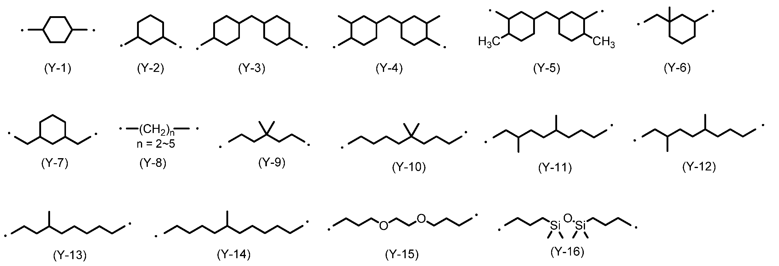
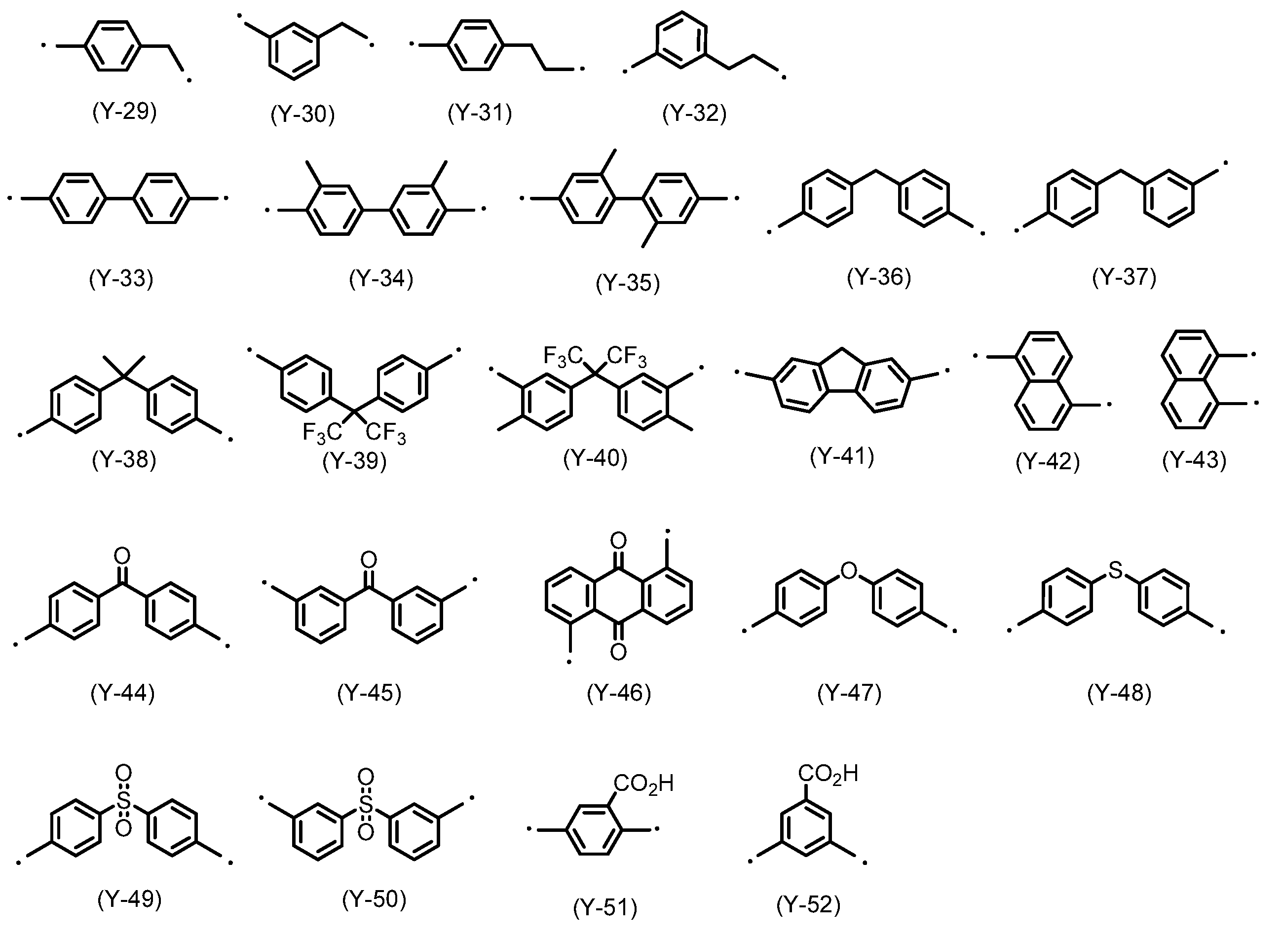
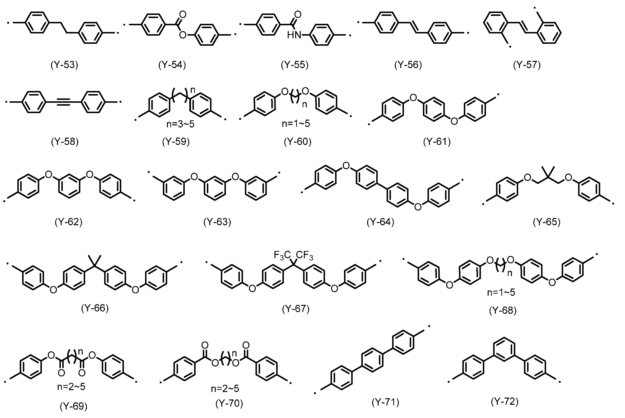
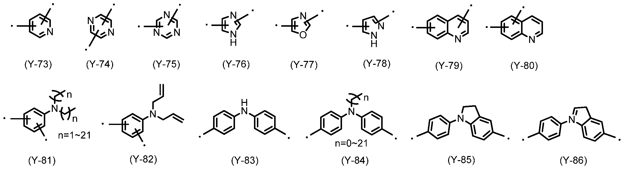
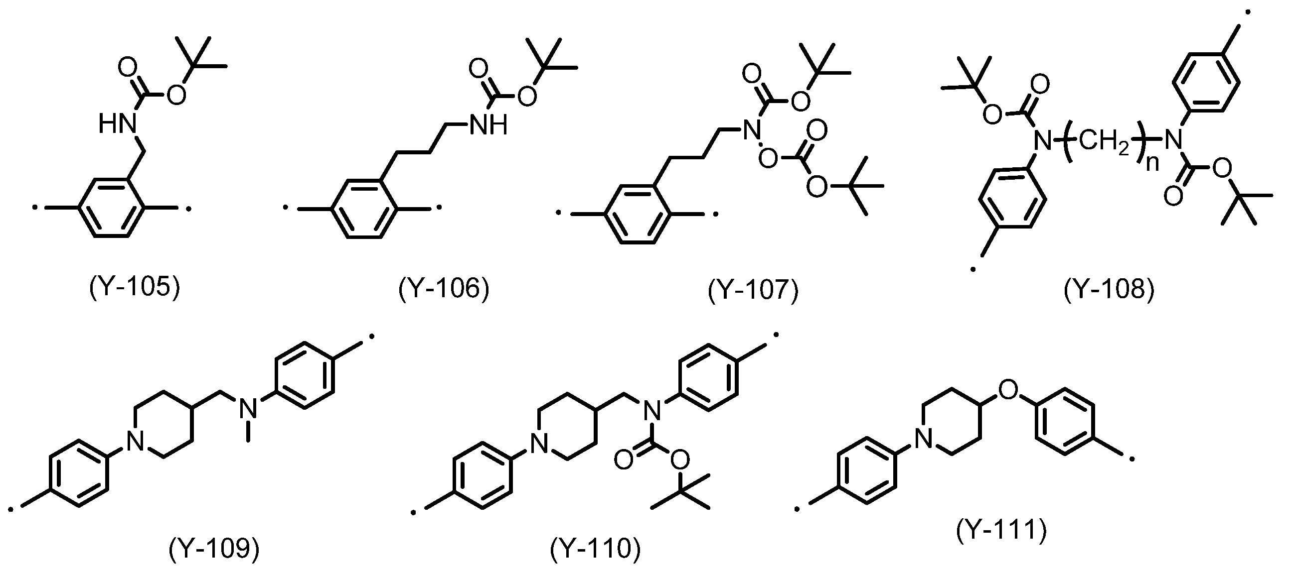
- the diamine used for the polyimide-based polymer contained in the liquid crystal structure stabilizer of the present invention in addition to the diamine containing the side chain structure described above, in a range that does not impair the characteristics of the obtained ULH liquid crystal display element, It is also possible to use a diamine in which R 2 has the following structure. In addition, the point in a formula is a part directly connected to an amino group.
- these diamine structures play a very important role in improving the rubbing resistance, so that positive introduction is preferable, and Y-82 and Y-94 to Y-108 are particularly preferable.
- Tetracarboxylic dianhydride can be represented by the following general formula (TC).
- TC tetravalent organic group
- X is a tetravalent organic group, and its structure is not particularly limited. There are no particular restrictions on the type of tetracarboxylic dianhydride used in the present invention, and it may be used alone or in combination of two or more depending on the characteristics such as voltage holding characteristics and accumulated charges when the liquid crystal alignment film is formed. it can.
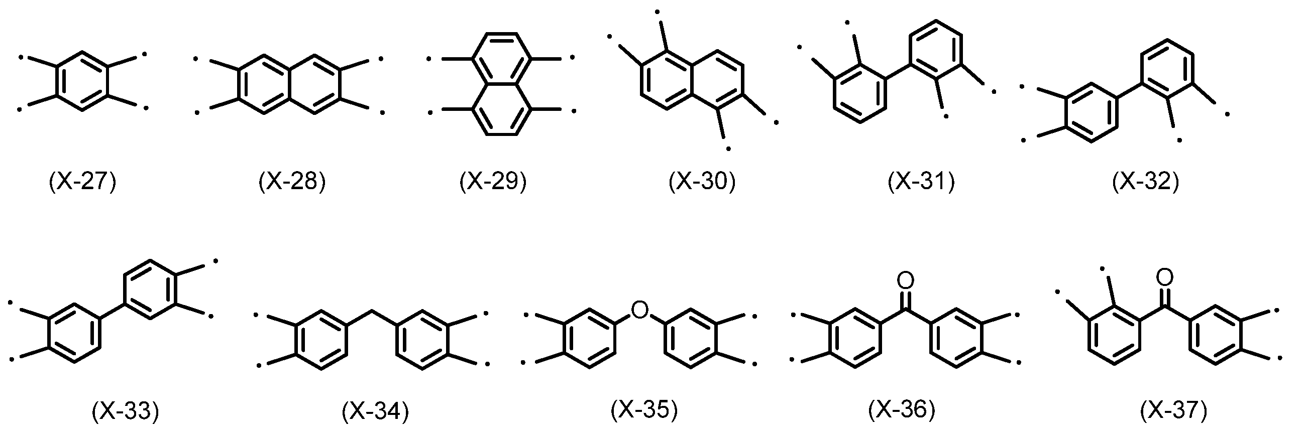
- a soluble polyimide since solubility in a solvent becomes an important physical property, an alicyclic tetracarboxylic dianhydride as shown in X-1 to 26 is preferred from the viewpoint of solubility, X-2, X-3, X-4, X-6, X-9, X-10, X-11, X-12, X-13, X-14, X-15, X-16, X- 17, X-18, X-19, X-20, X-21, X-22, X-23, X-24, X-25, X-26 are preferred.
- aromatic tetracarboxylic dianhydrides such as X27 to 46 are preferred from the viewpoint of orientation, and in particular, X-27, X-28, X-33, X-34, X-35, X-40, X-41, X-42, X-43, X-44, X-45 and X-46 are preferred. Particularly preferred are X-1, X-2, X-18 to 22, X-25, and X-26, which have moderate orientation and solubility.
- the liquid crystal structure stabilizer used in the liquid crystal display device of the present invention preferably contains a crosslinkable additive capable of improving rubbing resistance.
- crosslinkable additives include phenoplast additives, aminoplast additives, epoxy additives, acrylic additives, silane coupling agents, blocked isocyanate additives, oxazoline compounds, ⁇ -hydroxyalkyl Examples thereof include, but are not limited to, amide (primimide) crosslinking agents.
- phenoplast-based additive examples include but are not limited thereto.
- Crosslinkable compounds having at least one substituent selected from the group consisting of hydroxyl groups or alkoxyl groups include, for example, amino resins having hydroxyl groups or alkoxyl groups, such as melamine resins, urea resins, and guanamines. Resins, glycoluril-formaldehyde resins, succinylamide-formaldehyde resins, ethyleneurea-formaldehyde resins, and the like.
- this crosslinkable compound for example, a melamine derivative, a benzoguanamine derivative or glycoluril in which a hydrogen atom of an amino group is substituted with a methylol group or an alkoxymethyl group or both can be used.
- the melamine derivative and benzoguanamine derivative may exist as a dimer or a trimer. These preferably have an average of 3 to 6 methylol groups or alkoxymethyl groups per triazine ring.
- Examples of such melamine derivatives or benzoguanamine derivatives include MX-750, which has an average of 3.7 substituted methoxymethyl groups per triazine ring, and an average of 5. methoxymethyl groups per triazine ring.
- methoxymethylated melamines such as Cymel 300, 301, 303, 350, 370, 771, 325, 327, 703, 712, Cymel 235, 236 Methoxymethylated butoxymethylated melamine such as 238, 212, 253, 254, butoxymethylated melamine such as Cymel 506, 508, carboxyl group-containing methoxymethylated isobutoxymethylated melamine such as Cymel 1141, Cymel 1123 and the like
- Methoxymethylated ethoxy A methoxymethylated butoxymethylated benzoguanamine such as thymel 1128-10, butoxymethylated benzoguanamine such as thymel 1128, carboxyl group-containing methoxymethylated ethoxymethylated benzoguanamine such as thymel 1125-80 Cyanamide).
- glycoluril include butoxymethylated glycoluril such as Cymel 1170, methylol
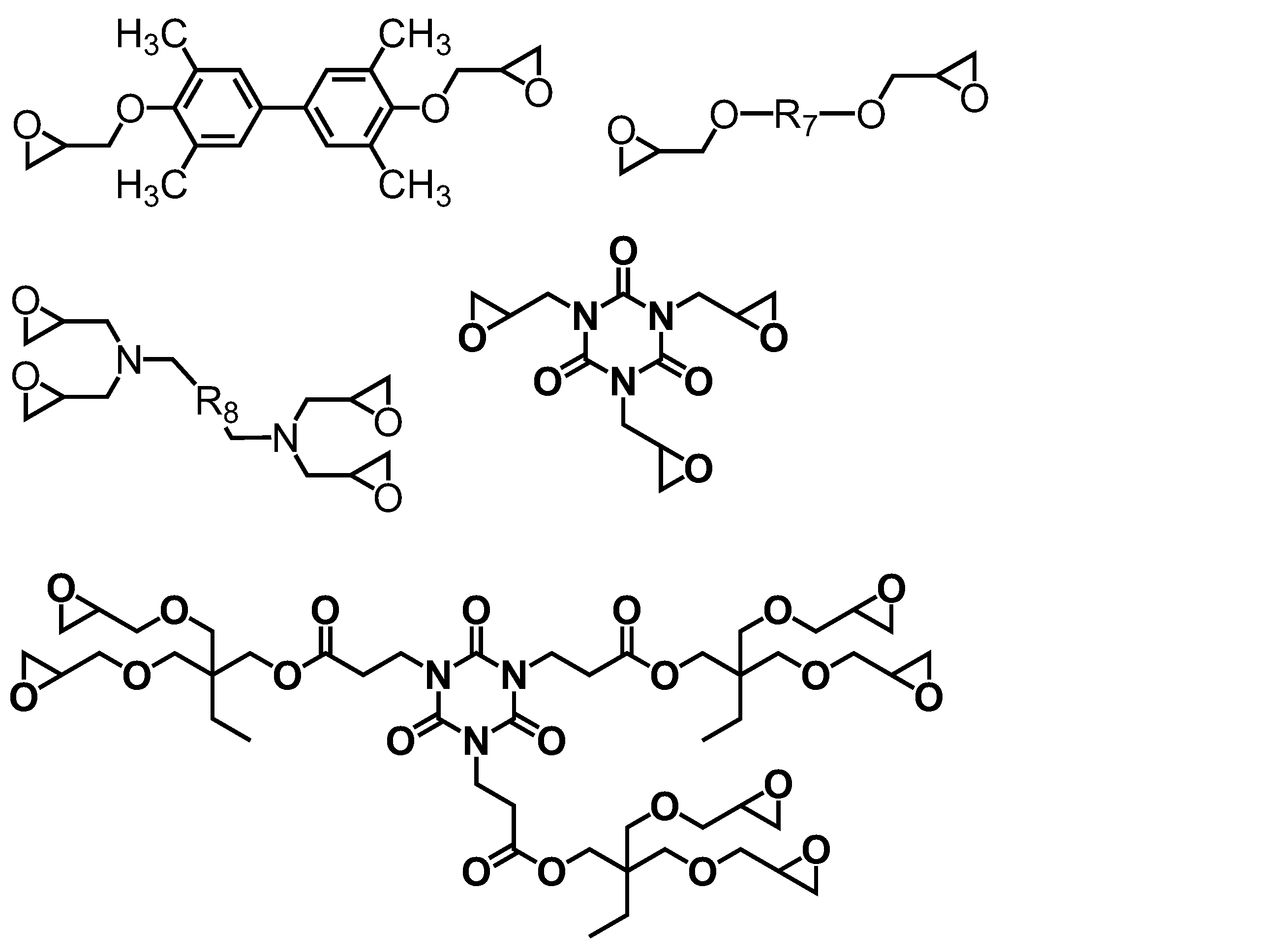
- Epoxy additives examples include bisphenolacetone glycidyl ether, phenol novolac epoxy resin, cresol novolac epoxy resin, triglycidyl isocyanurate, tetraglycidylaminodiphenylene, tetraglycidyl-m-xylene.
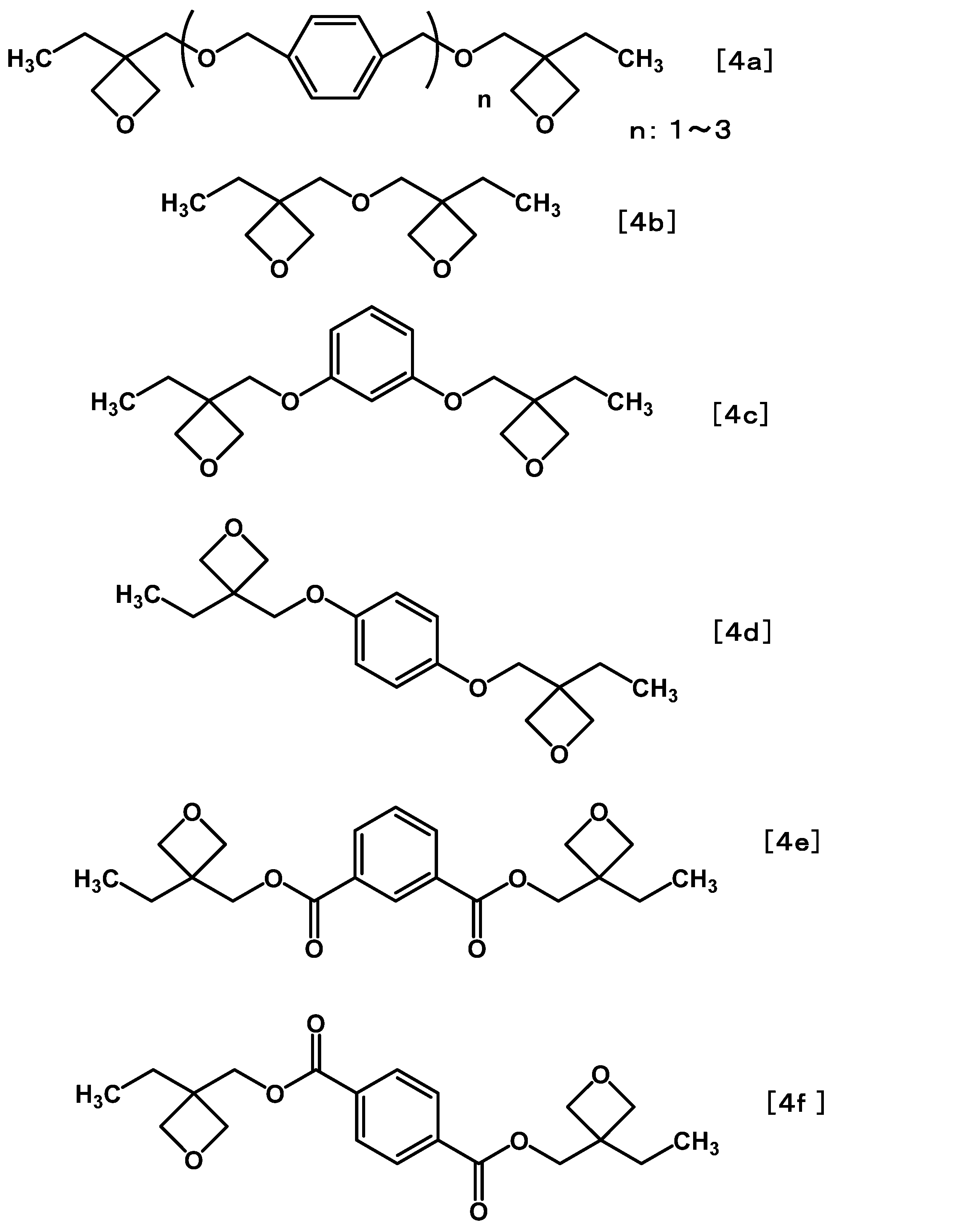
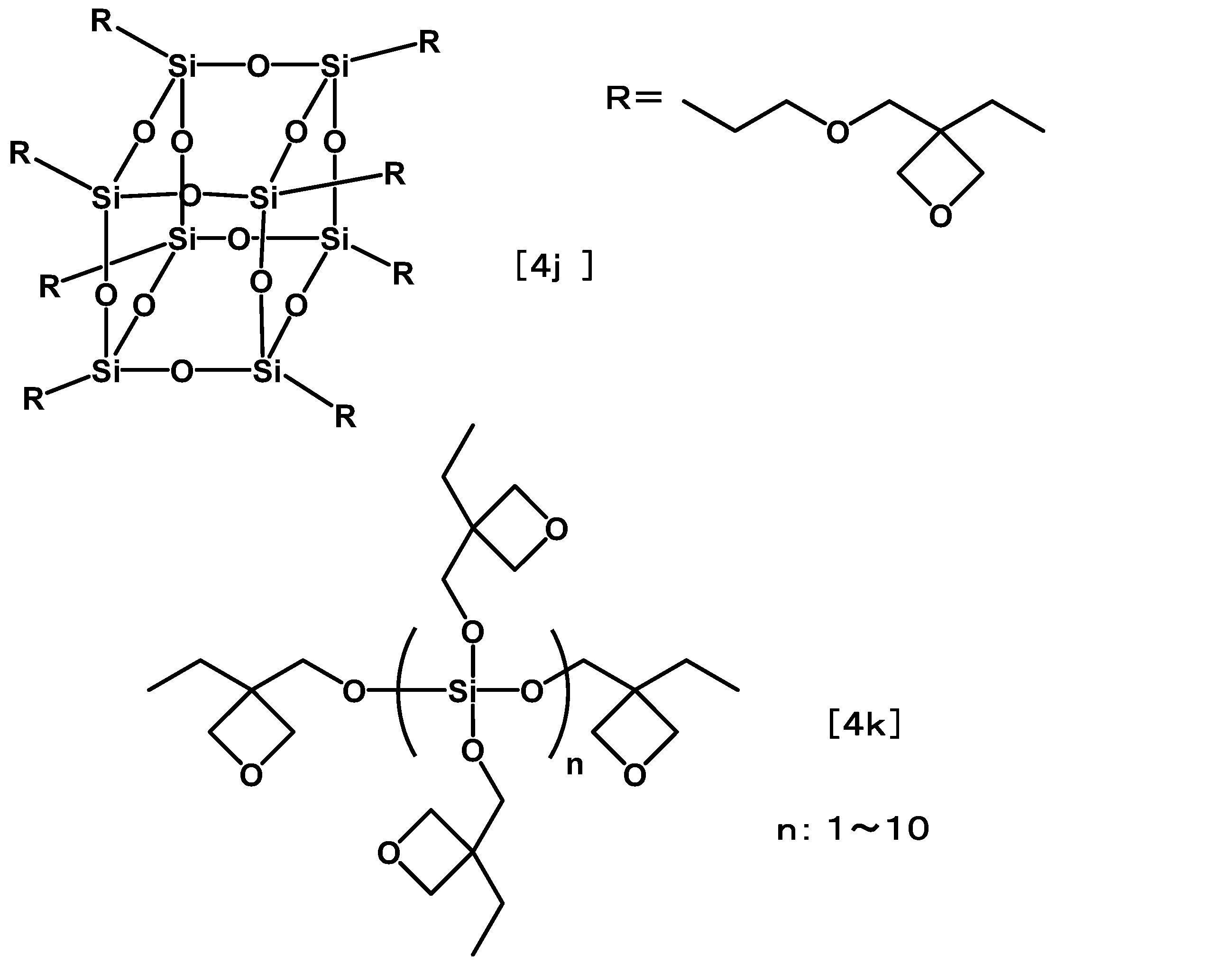
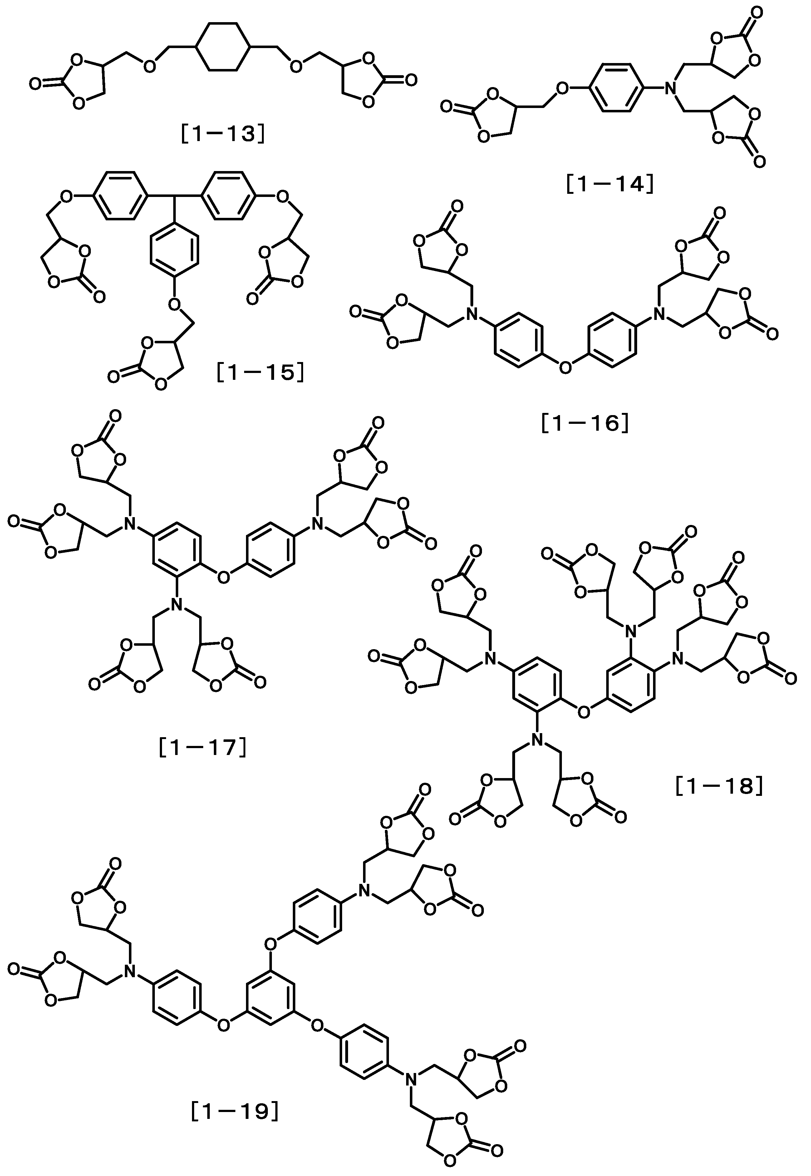
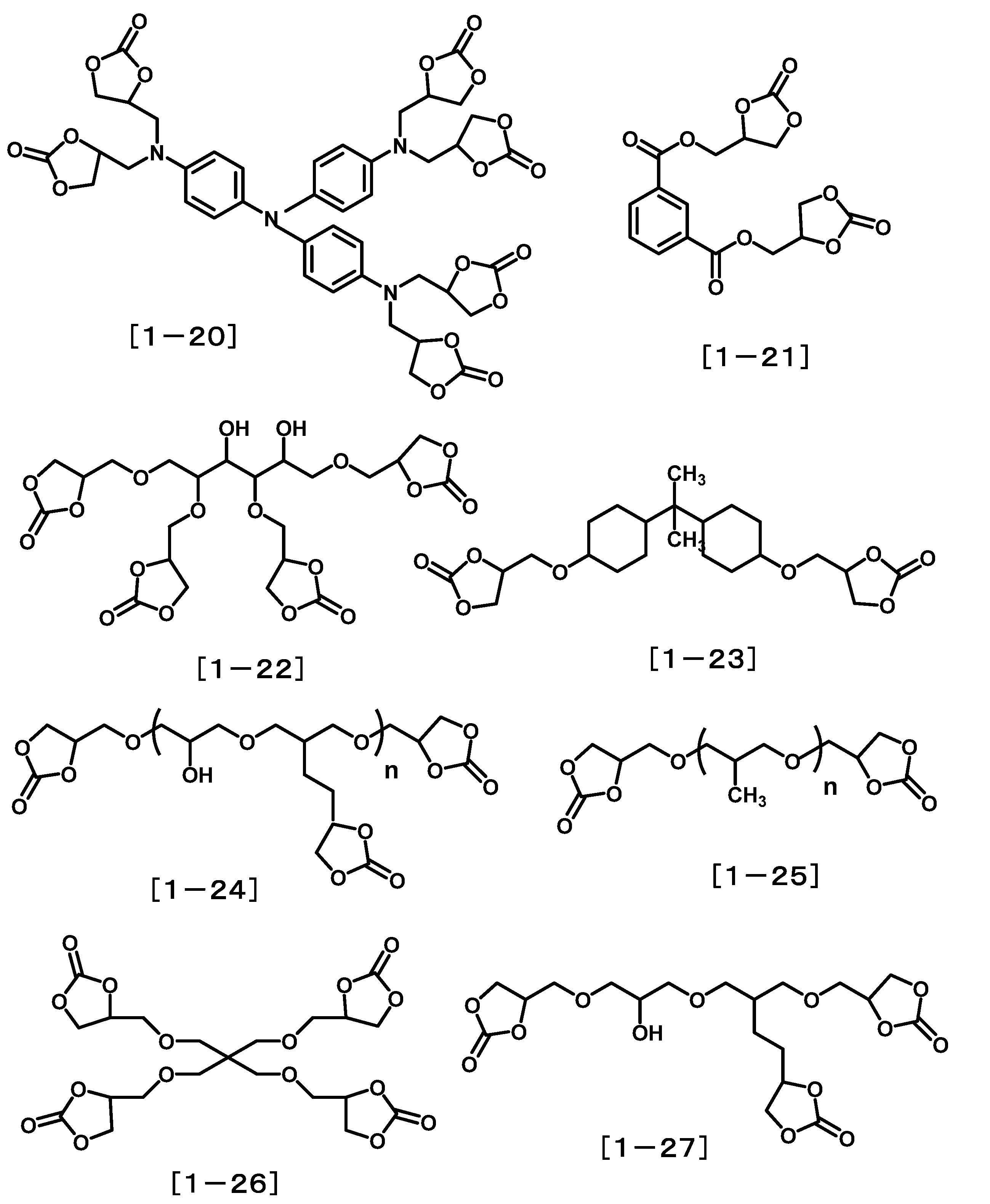
- the crosslinkable compound having an oxetane oxetane group is a crosslinkable compound having at least two oxetane groups represented by the following formula [4]. Specifically, it is a crosslinkable compound represented by the following formula [4a] to formula [4k].
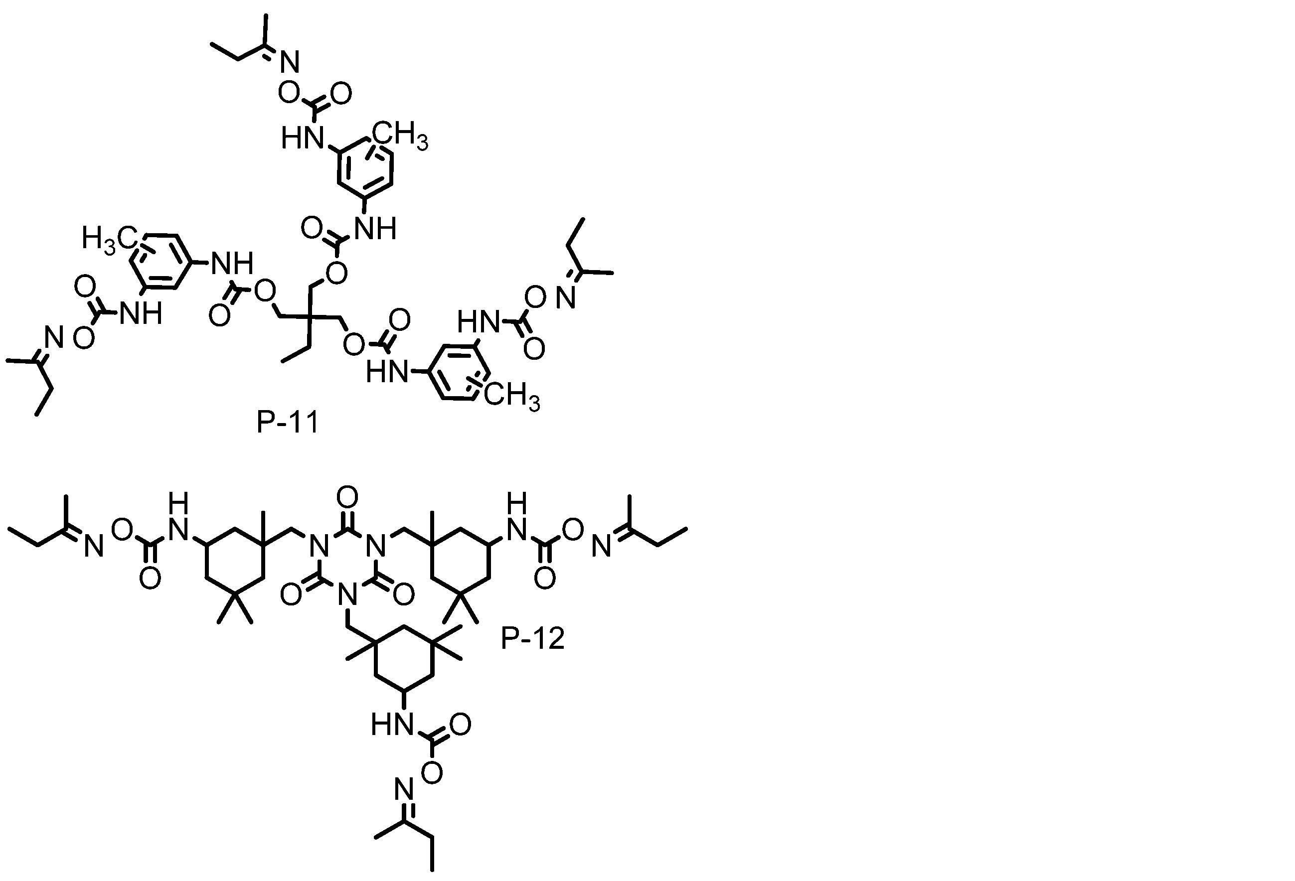
- Block isocyanate additive examples of the compound containing two or more blocked isocyanate groups include compounds having a blocked isocyanate group represented by the following formula (5).
- Z is each independently an alkyl group having 1 to 3 carbon atoms, a hydroxyl group, or an organic group represented by the following formula (6), and at least one of Z is an organic group represented by the following formula (6) It is.
- the following compounds are exemplified.
- Examples of the compound containing two or more blocked isocyanate groups other than the above formula (7) include the following compounds.
- Oxazoline compounds include 2,2'-bis (2-oxazoline), 1,2,4-tris- (2-oxazolinyl-2) -benzene, 4-furan-2-ylmethylene-2-phenyl- 4H-oxazol-5-one, 1,4-bis (4,5-dihydro-2-oxazolyl) benzene, 1,3-bis (4,5-dihydro-2-oxazolyl) benzene, 2,3-bis ( 4-isopropenyl-2-oxazolin-2-yl) butane, 2,2′-bis-4-benzyl-2-oxazoline, 2,6-bis (isopropyl-2-oxazolin-2-yl) pyridine, 2, 2'-isopropylidenebis (4-tert-butyl-2-oxazoline), 2,2'-isopropylidenebis (4-phenyl-2-oxazoline), 2,2'-me Renbisu (4-tert-but
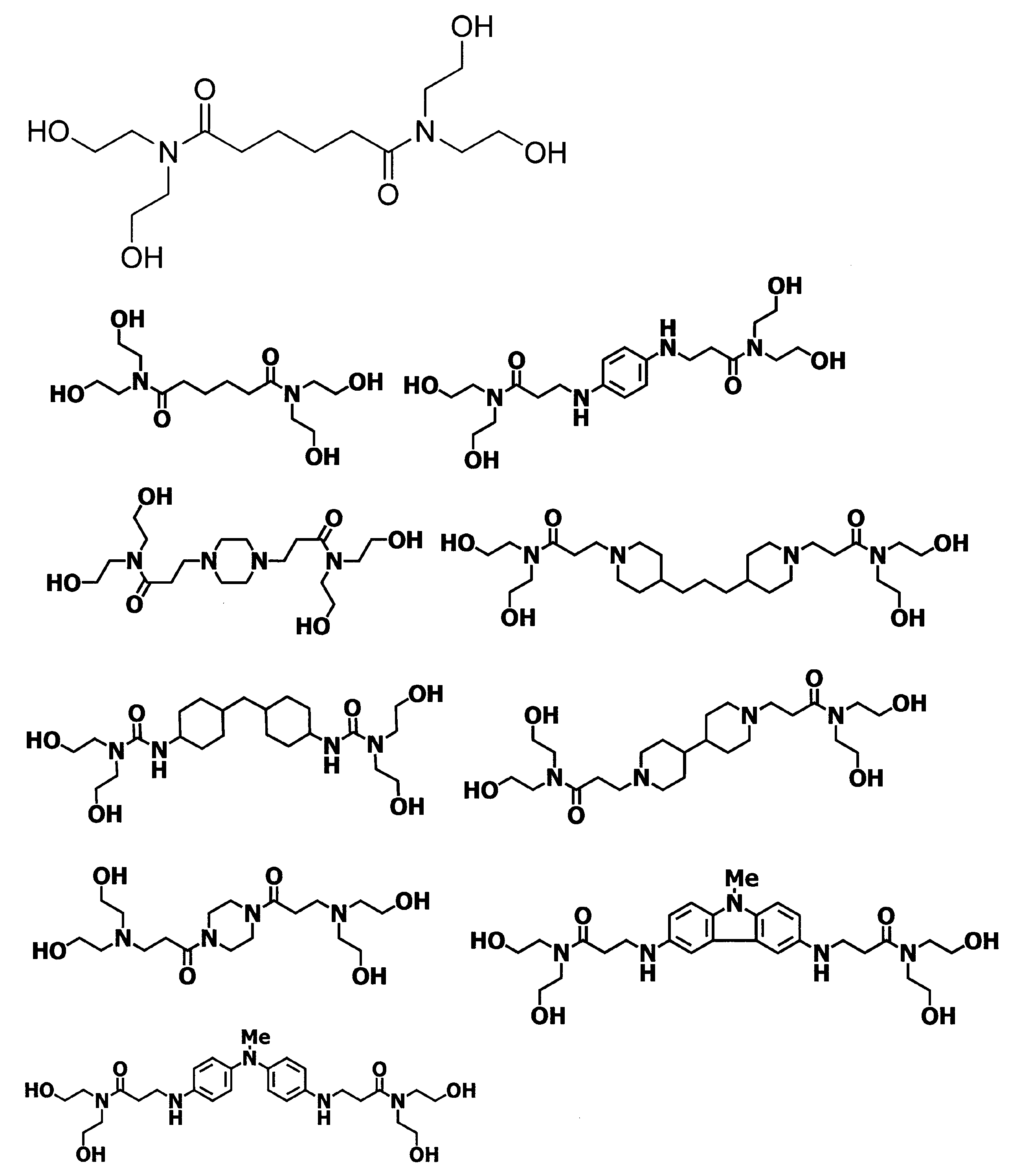
- Primid Cross-Linking Agent is a compound having a hydroxyalkylamide group.
- component (B) has a hydroxyalkylamide group
- other structures are not particularly limited, but from the viewpoint of availability, a preferred example includes a compound represented by the following formula (2).
- X 2 is an n-valent organic group containing an aliphatic hydrocarbon group having 1 to 20 carbon atoms or an aromatic hydrocarbon group.
- n is an integer of 2 to 6.
- R 2 and R 3 are each independently a hydrogen atom, an optionally substituted alkyl group having 1 to 4 carbon atoms, an optionally substituted alkenyl group having 2 to 4 carbon atoms, or An alkynyl group having 2 to 4 carbon atoms which may have a substituent. Further, at least one of R 2 and R 3 represents a hydrocarbon group substituted with a hydroxy group.
- X 2 (2) directly attached to atoms in a carbonyl group, it is preferable from the viewpoint of the liquid crystal orientation is a carbon atom, which do not form an aromatic ring.
- X 2 in the formula (2) is preferably an aliphatic hydrocarbon group and more preferably 1 to 10 carbon atoms from the viewpoint of liquid crystal alignment and solubility.
- n is preferably 2 to 4 from the viewpoint of solubility.
- R 2 and R 3 are preferably a structure represented by the following formula (3) from the viewpoint of reactivity, and a structure represented by the following formula (4) More preferably.
- R 4 to R 7 are each independently a hydrocarbon group substituted with a hydrogen atom, a hydrocarbon group, or a hydroxy group.
- component (B) include the following compounds.
- One kind of these crosslinkable additives may be added, but a plurality of kinds may be added as long as the characteristics of the present invention are not impaired.
- a preferred addition amount is 0.1 to 30% by weight, preferably 0.5 to 10% by weight.
- Crosslinkable compounds having a polymerizable unsaturated bond include trimethylolpropane tri (meth) acrylate, pentaerythritol tri (meth) acrylate, dipentaerythritol penta (meth) acrylate, tri Crosslinkable compounds having three polymerizable unsaturated groups in the molecule such as (meth) acryloyloxyethoxytrimethylolpropane and glycerin polyglycidyl ether poly (meth) acrylate, ethylene glycol di (meth) acrylate, diethylene glycol di ( (Meth) acrylate, tetraethylene glycol di (meth) acrylate, polyethylene glycol di (meth) acrylate, propylene glycol di (meth) acrylate, polypropylene glycol di (meth) acrylate Relate, butylene glycol di (meth) acrylate, neopent
- a 1 is a group selected from a cyclohexyl ring, a bicyclohexyl ring, a benzene ring, a biphenyl ring, a terphenyl ring, a naphthalene ring, a fluorene ring, an anthracene ring, or a phenanthrene ring
- a 2 is And a group selected from the following formula [5a] or [5b], and n is an integer of 1 to 4.
- the said compound is an example of a crosslinkable compound, It is not limited to these.
- the crosslinkable compound contained in the liquid crystal aligning agent of this invention may be one type, and may be combined two or more types.
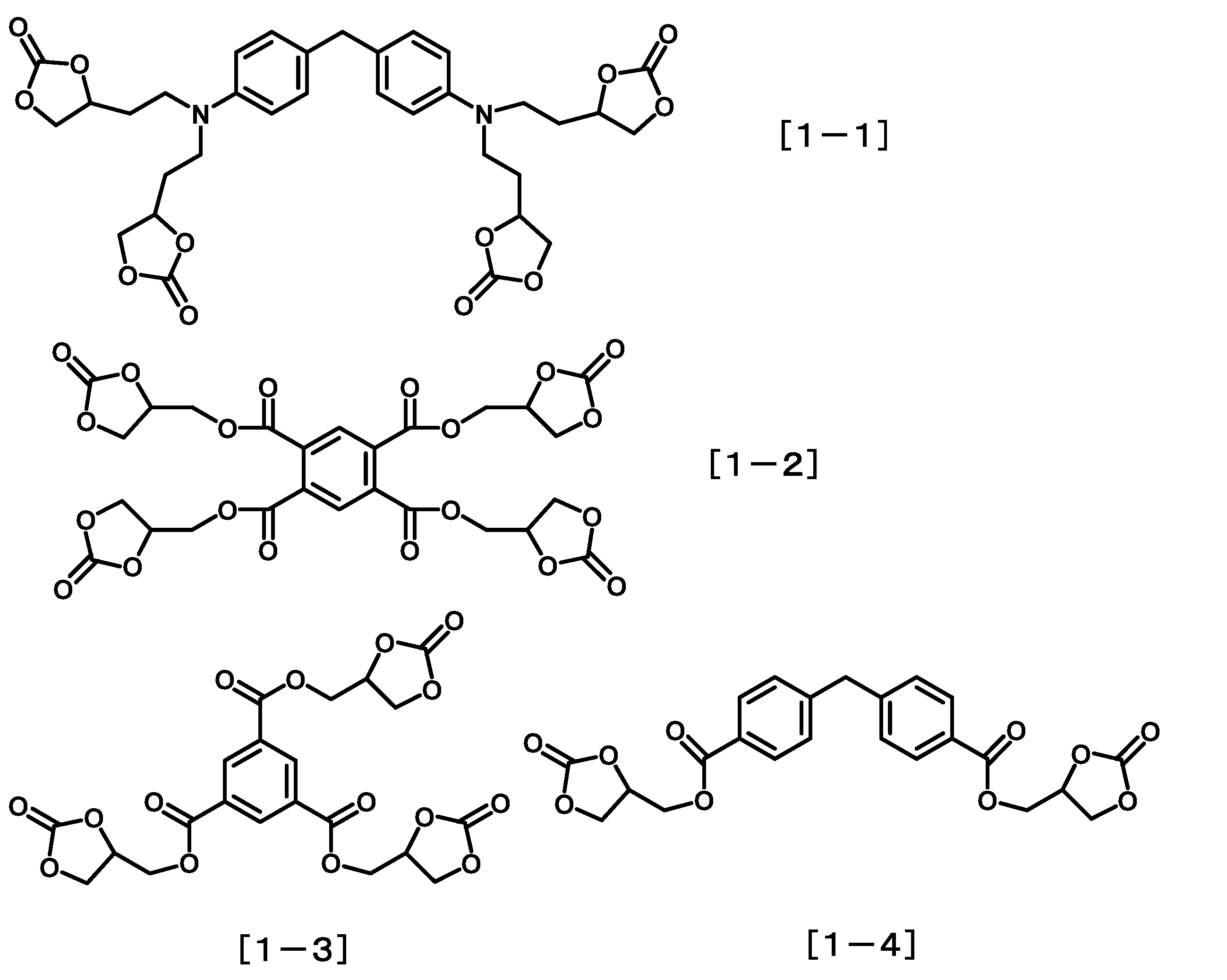
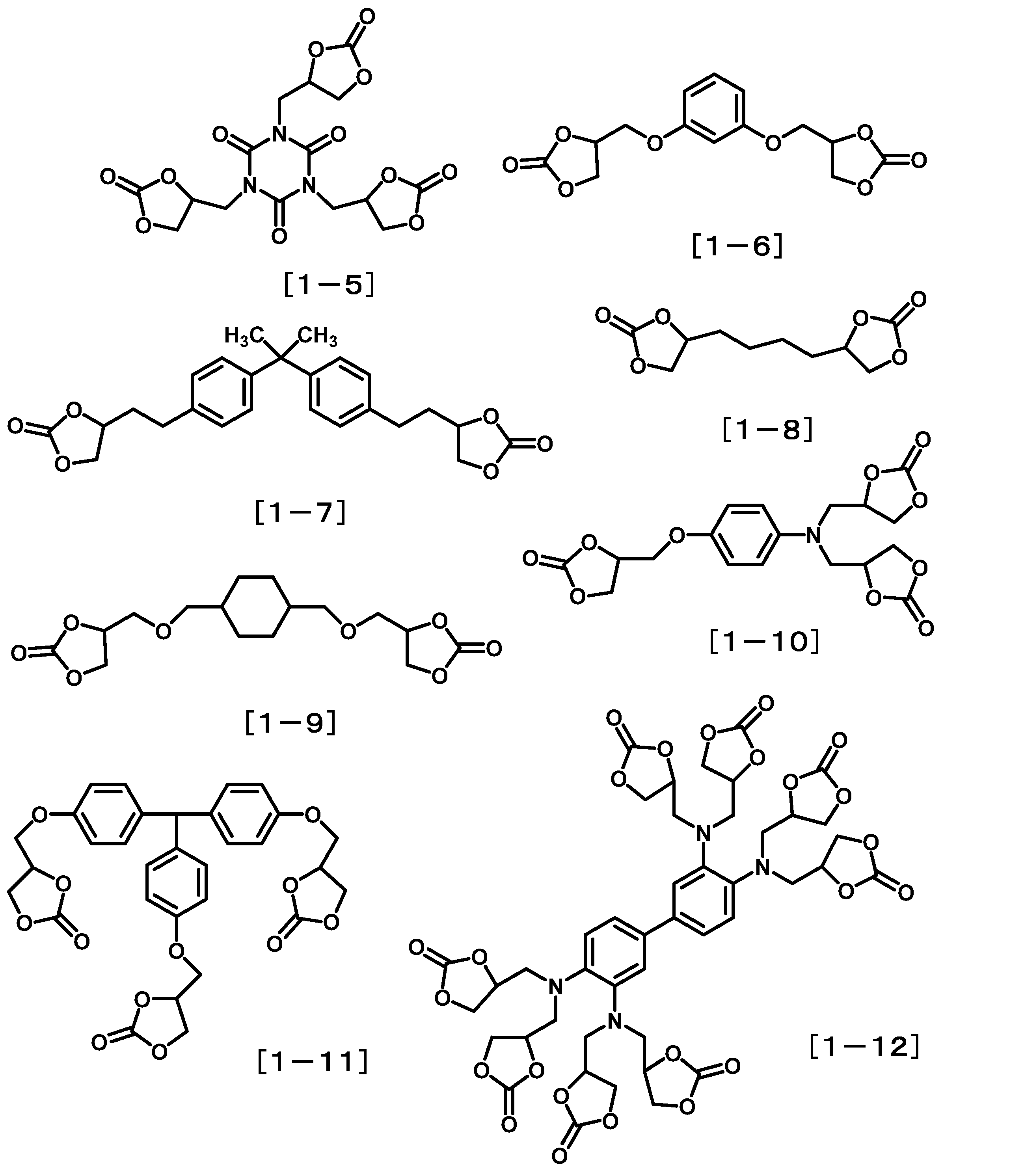
- Thiairan compounds include phenyl glycidyl ether, butyl glycidyl ether, 3,3,3-trifluoromethyl propylene oxide, styrene oxide, hexafluoropropylene oxide, cyclohexene oxide, N-glycidyl phthalimide, (nonafluoro-N-butyl) Epoxide, perfluoroethyl glycidyl ether, epichlorohydrin, epibromohydrin, N, N-diglycidyl aniline, and 3- [2- (perfluorohexyl) ethoxy] -1,2-epoxypropane, ethylene glycol di Glycidyl ether, polyethylene glycol diglycidyl ether, propylene glycol diglycidyl ether, tripropylene glycol diglycidyl ether, polypropylene glycol Diglycidyl ether, neopentyl glycol
- Aziridine Compound Examples of the aziridine compound include 2,4,6-tris (1′-aziridinyl) -1,3,5-triazine, ⁇ -aziridinylpropionic acid-2,2-dihydroxymethyl-butanol triester, 4,6-tris (2-methyl-1-aziridinyl) -1,3,5-triazine, 2,4,6-tris (2-ethyl-1-aziridinyl) -1,3,5-triazine, 4, 4′-bis (ethyleneiminocarbonylamino) diphenylmethane, bis (2-ethyl-1-aziridinyl) benzene-1,3-dicarboxylic acid amide, tris (2-ethyl-1-aziridinyl) benzene-1,3,5- Tricarboxylic acid amide, bis (2-ethyl-1-aziridinyl) sebacic acid amide, 1,6-bis (ethyleneimino
- the liquid crystal structure stabilizer used in the present invention may contain components other than the above polymer components and crosslinkable additives. Examples include solvents and compounds that improve the film thickness uniformity and surface smoothness when a liquid crystal structure stabilizer is applied, and compounds that improve the adhesion between the liquid crystal structure stabilizing film and the substrate. .
- Examples of the compound that improves the uniformity of the film thickness and the surface smoothness include a fluorine-based surfactant, a silicone-based surfactant, and a nonionic surfactant. More specifically, for example, F-top EF301, EF303, EF352 (manufactured by Tochem Products), MegaFuck F171, F173, R-30 (manufactured by Dainippon Ink), Florard FC430, FC431 (manufactured by Sumitomo 3M) ), Asahi Guard AG710, Surflon S-382, SC101, SC102, SC103, SC104, SC105, SC106 (Asahi Glass Co., Ltd.).
- the use ratio of these surfactants is preferably 0.01 to 2 parts by mass, more preferably 0.01 to 1 part by mass with respect to 100 parts by mass of the polymer component contained in the liquid crystal structure stabilizer. Part.
- the compound that improves the adhesion between the liquid crystal alignment film and the substrate include the following functional silane-containing compounds and epoxy group-containing compounds.
- the amount used is 0.1 to 30 parts by mass with respect to 100 parts by mass of the polymer component contained in the liquid crystal structure stabilizer.
- the amount is preferably 1 to 20 parts by mass. If the amount used is less than 0.1 parts by mass, the effect of improving the adhesion cannot be expected, and if it exceeds 30 parts by mass, the liquid crystal orientation may be deteriorated.
- the liquid crystal structure stabilizer of the present invention may be a dielectric material for the purpose of changing the electrical properties such as the dielectric constant and conductivity of the liquid crystal alignment film as long as the effects of the present invention are not impaired.
- a crosslinkable compound for the purpose of increasing the hardness and density of the film when the liquid crystal alignment film is formed may be added.
- the liquid crystal structure stabilizer used in the present invention contains the above polymer and additive dissolved in an organic solvent.
- the liquid crystal structure stabilizer contains the above polymer in an amount of preferably 1 to 15% by mass, more preferably 2 to 10% by mass, and still more preferably 2 to 8% by mass.
- the liquid crystal structure stabilizer of the present invention includes a polyamic acid other than the above-mentioned polymer, a polyamic acid ester, a polyimide obtained by imidizing them, and other polymers (or more) as long as the effects of the present invention are not impaired. These may also be referred to as “other polymers”).
- the content is preferably 10 to 1000 parts by mass, more preferably 10 to 800 parts by mass with respect to 100 parts by mass of the polymer. May be.
- the organic solvent contained in the liquid crystal structure stabilizer is preferably 90 to 97% by mass, more preferably 93 to 96% by mass.
- the organic solvent used for dissolving each polymer is not particularly limited as long as it is an organic solvent capable of dissolving the polymer component. Specific examples are given below.
- membrane of this invention can be manufactured as follows, for example.
- the first method is a conventionally known method. First, two substrates are arranged opposite to each other with a gap (cell gap) so that the respective liquid crystal structure stabilizing films are opposed to each other, and the peripheral portions of the two substrates are bonded together using a sealant, and the substrate surface A liquid crystal cell can be manufactured by injecting and filling liquid crystal into the cell gap defined by the sealing agent and then sealing the injection hole.
- the method for obtaining the cell gap is not particularly limited, but a method in which spacer beads (aluminum oxide spheres) and the like are evenly spread on a substrate provided with a liquid crystal structure stabilizing film and then bonded, or a sealant without being spread.
- Examples thereof include a method of providing a cell gap by dispersing and applying spacer beads therein, and using a substrate provided with a structure so as to have a specific cell gap in advance using a photoresist or the like. Since the orientation of ULH is strongly influenced by foreign matter and the like, it is preferable that there is no spacer bead in the pixel.
- the second method is a method called an ODF (One Drop Fill) method.
- ODF One Drop Fill
- a liquid crystal cell can be manufactured by bonding the other substrate so that the liquid crystal structure stabilizing film faces each other, and then irradiating the entire surface of the substrate with ultraviolet light to cure the sealant.
- the sealing agent for example, an epoxy resin containing a curing agent can be used.
- an epoxy resin containing a curing agent can be used.
- it is desirable to remove the flow alignment at the time of filling the liquid crystal by heating the liquid crystal cell to a temperature at which the liquid crystal used has an isotropic phase and then gradually cooling it to room temperature.
- the liquid crystal used in the ULH alignment mode is a cholesteric liquid crystal, but in order to obtain a more stable ULH alignment, it is necessary to use a liquid crystal capable of obtaining a strong flexoelectric effect.
- the liquid crystal capable of obtaining the flexoelectric effect include the following bimesogen type liquid crystal, and ULH alignment can be obtained by using a cholesteric liquid crystal containing these structures, but is not limited thereto. (Wherein X 1 and X 2 each independently represent a linking group selected from a single bond, an ester bond and an ether bond, and L is an integer represented by 6 to 20).
- a material in which 1 to 5% by weight of a chiral agent having a strong helical twist power is added is not particularly limited as long as it is obtained, but particularly preferred chiral agents include the following compounds. (Wherein X 1 and X 2 each independently represents a linking group selected from a single bond, an ester bond and an ether bond, and R 8 represents a 3 to 10 alkyl group.)
- the cholesteric liquid crystal can be transferred to a ULH alignment by injecting it into the liquid crystal cell provided with the alignment film and applying an electric field together with the heat treatment. For example, by raising the temperature to the isotropic phase of the liquid crystal used, confirming that it has completely changed to the isotropic phase, and inducing ULH alignment by slowly returning to room temperature while applying a voltage to the liquid crystal cell. Can do.
- the preferred temperature drop rate and the type and intensity of applied voltage cannot be limited, but the temperature drop rate from the temperature at which it is isotropic is preferably 1 to
- the applied voltage is preferably a rectangular wave alternating current with an electric field strength of 1 to 10 V / ⁇ m, preferably 2 to 8 / ⁇ m, and the frequency is 1 to 1 KHz, more preferably 10 to 10 ° C. 300 Hz is preferred.
- a desired liquid crystal display element can be obtained by bonding a polarizing plate to the outer surface of the liquid crystal cell.
- a liquid crystal display element can be obtained.
- the polarizing plate used outside the liquid crystal cell is composed of a polarizing film called “H film” in which polyvinyl alcohol is stretched and oriented while absorbing iodine and sandwiched between cellulose acetate protective films, or the H film itself.
- H film a polarizing film
- the evaluation method of the implemented liquid crystal structure stabilizer is as follows. ⁇ Viscosity measurement> The viscosity of the polyamic acid solution was measured using an E-type viscometer TVE-22H (manufactured by Toki Sangyo Co., Ltd.) at a sample amount of 1.1 mL, cone rotor TE-1 (1 ° 34 ′, R24), and a temperature of 25 ° C. . ⁇ Measurement of imidization ratio> The imidation ratio of polyimide was measured as follows.
- Imidation rate (%) (100 ⁇ Polyamic acid polymerization formula (1) Amount of diamine introduced (mol%) / 2) ⁇ ⁇
- ⁇ is a proton derived from a structure that does not change before and after imidation as a reference proton, and a proton peak integrated value and a proton peak derived from the NH group of an amic acid that appears in the vicinity of 9.5 to 10.0 ppm. Using the integrated value, it was determined by the following equation.
- ⁇ (1 ⁇ ⁇ x / y)
- x is the proton peak integrated value derived from the NH group of the amic acid
- y is the peak integrated value of the reference proton
- ⁇ is one NH group proton of the amic acid in the case of polyamic acid (imidation rate is 0%). The number ratio of the reference protons.
- PAA-1 polyamic acid solution
- 100 g of PAA-1 obtained in a 500 ml Erlenmeyer flask was weighed, and 130.77 g of NMP, acetic anhydride (35.43 g: 347.00 mmol) and pyridine (16.48 g: 208.20 mmol) were added in this order, and at room temperature. After stirring for 30 minutes, the mixture was reacted at 45 ° C. for 3 hours. After completion of the reaction, the reaction solution was poured into 1000 ml of cooled methanol with stirring to precipitate a solid.
- the obtained solid was collected by filtration, further washed with stirring with 500 ml of methanol twice, and then vacuum dried at 100 ° C. to obtain a soluble polyimide (SPI-1) as a white solid.
- the imidation ratio of the obtained polyimide was 87%, and the weight average molecular weight was 32000.
- a 300 ml Erlenmeyer flask equipped with a stir bar 5.00 g of SPI-1 obtained by the above operation was measured, 45.00 g of GBL was added, and the mixture was stirred at 50 ° C. for 16 hours to completely dissolve it.
- PAA-2 a polyamic acid solution
- a soluble polyimide (SPI-2) as an orange solid.
- the imidation ratio of the obtained polyimide was 85%, and the weight average molecular weight was 37000.
- a stirring bar 5.00 g of SPI-2 obtained by the above operation was measured, 45.00 g of GBL was added, and the mixture was stirred at 50 ° C. for 16 hours to completely dissolve it.
- 16.67 g of NMP, 16.67 g of BCS, Ad-1 (0.50 g: 10% by mass with respect to SPI-2) was added, and the mixture was stirred at room temperature for 24 hours, and the liquid crystal structure stabilizer used in the present invention (Hereinafter AL-2) was obtained.
- Example 3 Synthesis example 3 DA-4 (1.95 g: 16.00 mmol), DA-5 (8.13 g: 40.00 mmol), DA-7 (9.78 g: 24) were added to a 200 ml four-necked flask equipped with a nitrogen inlet tube and a stirring bar. 0.000 g) was measured, 143.00 g of NMP was added, and the mixture was stirred at 50 ° C. in a nitrogen atmosphere to be completely dissolved. To this solution was added TC-3 (2.62 g: 12.00 mmol), and the mixture was stirred and reacted for 30 minutes. Then, TC-1 (13.26 g: 67.60 mmol) was added, and the temperature was returned to room temperature.
- PAA-3 polyamic acid solution
- acetic anhydride 20.78 g: 203.50 mmol
- pyridine 8.91 g
- the obtained solid was collected by filtration, further washed with stirring with 500 ml of methanol twice, and then dried under vacuum at 100 ° C. to obtain a soluble polyimide (SPI-3) as an orange solid.
- the imidation ratio of the obtained polyimide was 83%, and the weight average molecular weight was 32000.
- a 300 ml Erlenmeyer flask equipped with a stirring bar 5.00 g of SPI-3 obtained by the above operation was measured, 45.00 g of GBL was added, and the mixture was stirred at 50 ° C. for 16 hours to completely dissolve it.
- Example 4 In a 100 ml Erlenmeyer flask equipped with a stir bar, AL-2 (25.0 g) and AL-3 (25.0 g) obtained in Example 2 and Example 3 were measured and stirred at room temperature for 24 hours. A liquid crystal structure stabilizer (hereinafter referred to as AL-4) used in the invention was obtained.
- Example 5 Synthesis example 4 DA-8 (1.13 g: 3.00 mmol) and DA-9 (7.73 g: 27.00 mmol) were measured in a 200 ml four-necked flask equipped with a nitrogen inlet tube and a stirring bar, and 109.60 g of NMP was added. It was completely dissolved under a nitrogen atmosphere. This solution was cooled to 10 ° C. or lower, TC-3 (6.09 g: 27.9 mmol) was added, the temperature was returned to room temperature, and the reaction was performed in a nitrogen atmosphere for 24 hours to obtain a polyamic acid solution (hereinafter referred to as PAA-4). . The obtained PAA-4 had a weight average molecular weight of 31,700.
- the obtained PAA-5 had a weight average molecular weight of 29000.
- 100 g of the above-obtained PAA-5 was measured, 112.50 g of GBL and 37.50 g of BCS were added, and the mixture was stirred at room temperature for 24 hours.
- the following AL-6) was obtained.
- Comparative Example 2 A liquid crystal structure stabilizer not added with Ad-1 was prepared as the liquid crystal structure stabilizer obtained by the procedure of Synthesis Example 1 to obtain a liquid crystal structure stabilizer AL-7 to be compared.
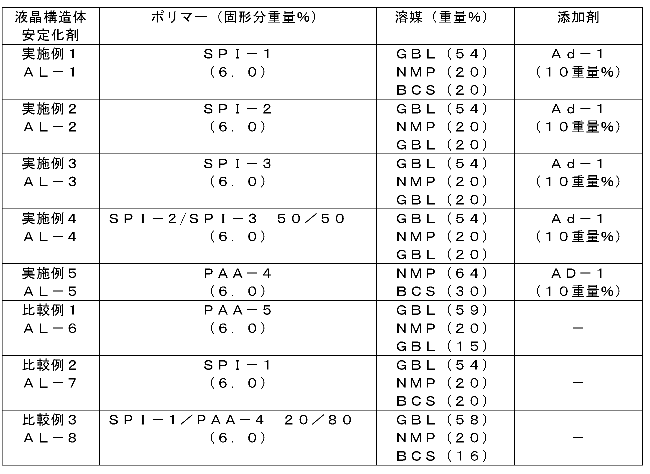
- the following table shows the composition of the polymer prepared in the above synthesis example and the composition of the liquid crystal structure stabilizer.
- This liquid crystal structure stabilizing film is rubbed with a rayon cloth (YA-20R manufactured by Yoshikawa Chemical Industries) (roller diameter: 120 mm, roller rotation speed: 700 rpm, moving speed: 50 mm / sec, indentation length: 0.2 mm), and then pure. Washing was performed by irradiating with ultrasonic waves in water for 1 minute, and water droplets were removed by air blowing, followed by drying at 80 ° C. for 15 minutes to obtain a substrate with a liquid crystal structure stabilizing film. The uniformity of the obtained film was subjected to surface analysis using a DFM (Direct Force Atomic Force Microscope: manufactured by Hitachi High-Tech), and the roughness per 10 ⁇ m was calculated and compared.
- DFM Direct Force Atomic Force Microscope: manufactured by Hitachi High-Tech
- ⁇ Creation of substrate with liquid crystal structure stabilization film> After the liquid crystal structure stabilizer is filtered through a 1.0 ⁇ m filter, a substrate with an electrode (a glass substrate having a size of 30 mm wide ⁇ 40 mm long and 1.1 mm thick. The electrode is 10 mm wide ⁇ 40 mm long) A rectangular ITO electrode having a thickness of 35 nm was applied by spin coating. After drying on a hot plate at 80 ° C. for 1 minute, baking was performed in an IR oven at 220 ° C. for 20 minutes to form a coating film having a thickness of 100 nm to obtain a substrate with a liquid crystal structure stabilizing film.
- This liquid crystal structure stabilizing film is rubbed with a rayon cloth (YA-20R manufactured by Yoshikawa Chemical Industries) (roller diameter: 120 mm, roller rotation speed: 700 rpm, moving speed: 50 mm / sec, indentation length: 0.2 mm), and then pure. Washing was performed by irradiating with ultrasonic waves in water for 1 minute, and water droplets were removed by air blowing, followed by drying at 80 ° C. for 15 minutes to obtain a substrate with a liquid crystal structure stabilizing film.
- YA-20R manufactured by Yoshikawa Chemical Industries rayon cloth (YA-20R manufactured by Yoshikawa Chemical Industries) (roller diameter: 120 mm, roller rotation speed: 700 rpm, moving speed: 50 mm / sec, indentation length: 0.2 mm)
- the empty cell obtained as described above was placed on a hot plate heated to 80 ° C., and liquid crystal was injected by capillary injection using a liquid crystal for ULH mode manufactured by Merck, and the liquid crystal inlet was sealed.
- a cell for ULH evaluation was created.
- the schematic diagram is shown in FIG. ⁇ Observation of ULH initial orientation> The orientation was evaluated using a polarizing microscope (POM) with a stage capable of being heated and cooled.
- the liquid crystal cell obtained as described above is attached to the heating / cooling stage, the temperature is raised to a temperature at which the liquid crystal becomes isotropic, and after confirming that the liquid crystal is completely isotropic, 14 Vp-p is obtained with a function generator.
- POM polarizing microscope
- the measurement was performed using an Axoscan Mueller matrix polarimeter manufactured by Axometrix.
- liquid crystal structure stability prepared using a liquid crystal structure stabilizer containing a polyamic acid or soluble polyimide having side chains introduced therein and an additive capable of improving rubbing resistance Even after rubbing, the chemical film did not have rubbing scrapes or dust, and showed very low roughness. In addition, when an alignment film having a low roughness is used, a good ULH alignment is obtained. On the other hand, a polyamic acid material that does not contain a side chain as in Comparative Example 1 has a good ULH despite low roughness. No orientation was obtained, and it can be seen that soluble polyimide having side chains is significant for the orientation of ULH.
- the liquid crystal display element manufactured using the liquid crystal structure stabilizer of the present invention is excellent in various properties such as display characteristics and electrical characteristics, and is suitable for a large-screen, high-definition liquid crystal television. Available.
Landscapes
- Physics & Mathematics (AREA)
- Chemical & Material Sciences (AREA)
- Nonlinear Science (AREA)
- Crystallography & Structural Chemistry (AREA)
- General Physics & Mathematics (AREA)
- Optics & Photonics (AREA)
- Health & Medical Sciences (AREA)
- Mathematical Physics (AREA)
- Spectroscopy & Molecular Physics (AREA)
- Chemical Kinetics & Catalysis (AREA)
- Medicinal Chemistry (AREA)
- Polymers & Plastics (AREA)
- Organic Chemistry (AREA)
- Liquid Crystal (AREA)
- Compositions Of Macromolecular Compounds (AREA)
- Macromolecular Compounds Obtained By Forming Nitrogen-Containing Linkages In General (AREA)
Abstract
Description
[1]
液晶構造体を安定化する膜を形成するための組成物(上記「液晶構造体安定化剤」と同義である)であって、
側鎖構造を含有するポリアミック酸、側鎖構造を含有するポリアミック酸エステル、及び前記ポリアミック酸又はポリアミック酸エステルをイミド化したポリイミドからなる群から選ばれる少なくとも1種の重合体と、
ラビング耐性を向上させることのできる添加剤と
を含有する組成物。
[2]
前記少なくとも1種の重合体が、下記式から選ばれる少なくとも1種のジアミンを含有するジアミン成分と、テトラカルボン酸二無水物成分との反応生成物であるポリアミック酸、ポリアミック酸エステル、又は可溶性ポリイミドである、[1]に記載の組成物。
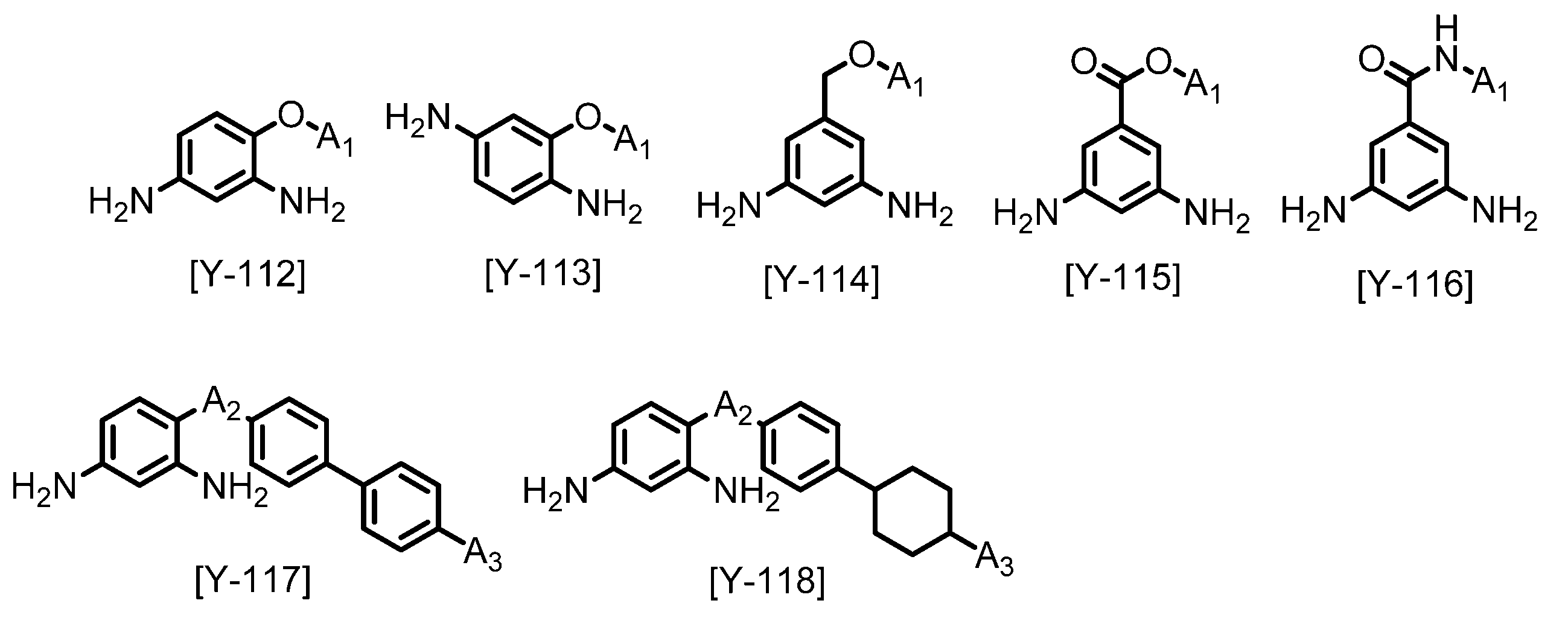
(A1は、炭素数2~24のアルキル基もしくはフッ素含有アルキル基、又はコレステロール基を表し、A2は、-O-、-OCH2-、-CH2O-、-COOCH2-、-NHCO-、-CONH-、又は-CH2OCO-を表し、A3は炭素数1~22のアルキル基、アルコキシ基、フッ素含有アルキル基、又はフッ素含有アルコキシ基を表す。)
[3]
前記ラビング耐性を向上させることのできる添加剤が、フェノプラスト系添加剤、アミノプラスト系添加剤、エポキシ系添加剤、アクリル系添加剤、シランカップリング剤、ブロックイソシアネート系添加剤、及びオキサゾリン系化合物からなる群より選択される、[1]又は[2]に記載の組成物。
[4]
前記少なくとも1種の重合体が、50%~100%のイミド化率を有する可溶性ポリイミドを含む、[1]乃至[3]のいずれか一項に記載の組成物。
[5]
コレステリック液晶をULH配向させるための膜を形成するための組成物である、[1]乃至[4]のいずれか一項に記載の組成物。
[6]
側鎖構造を含有するポリアミック酸、側鎖構造を含有するポリアミック酸エステル、及び前記ポリアミック酸又はポリアミック酸エステルをイミド化したポリイミドからなる群から選ばれる少なくとも1種の重合体と、
ラビング耐性を向上させることのできる添加剤と
を含有し、
表面平均面粗さRaが1.0nm以下である、
液晶構造体を安定化するための膜(以下、「液晶構造体安定化膜」と称することがある)。
[7]
ネマティック液晶を用いて測定したプレチルト角が3°~20°である、[6]に記載の膜。
[8]
配向処理後の表面平均面粗さRaが1.0nm以下である、[6]又は[7]に記載の膜。
[9]
前記配向処理が、布の摩耗が少なくなるような処理が施されたレーヨンやコットンを用いてラビング処理を行うことによる液晶の一軸配向性の付与である、[8]に記載の膜。
[10]
コレステリック液晶をULH配向させるための膜である、[6]乃至[9]のいずれか一項に記載の膜。
[11]
[6]乃至[10]のいずれか一項に記載の膜を有する、液晶構造体安定化膜付き基板。
[12]
それぞれの液晶構造体安定化膜が対向するように配置された[11]に記載の液晶構造体安定化膜付き基板の間に液晶を含む、液晶セル。
[13]
前記液晶がコレステリック液晶である、[12]に記載の液晶セル。
[14]
前記コレステリック液晶が、下記一般式で表される液晶性化合物を含有して成るコレステリック液晶である[13]に記載の液晶セル。
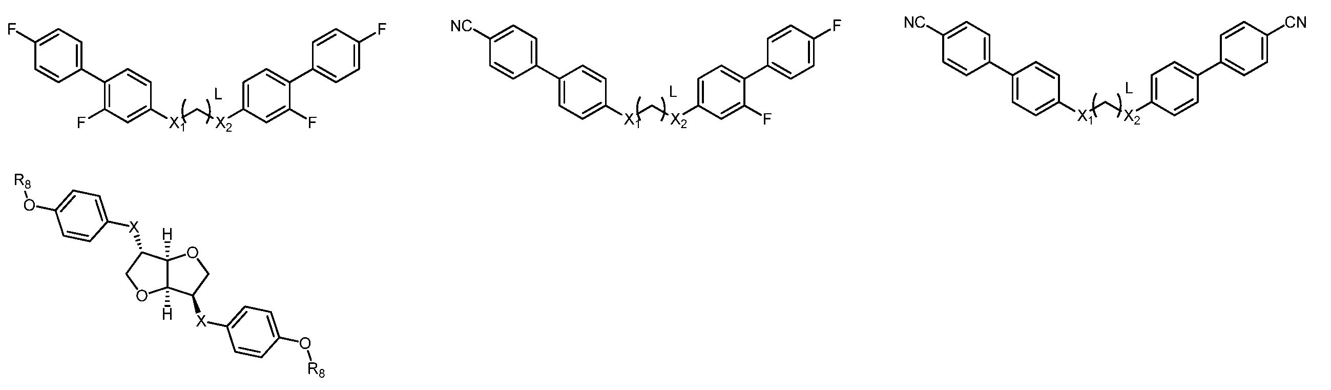
X1、X2はそれぞれ独立して単結合、エステル結合、エーテル結合から選ばれる連結基を表し、Lは6~20で表される整数であり、R8は炭素数4~10のアルキル基である。
[15]
偏光板、及び[12]乃至[14]のいずれか一項に記載の液晶セルを備えた液晶表示素子。
1.液晶構造体安定化膜
本発明に使用される液晶構造体安定化膜は、配向処理後の表面平均面粗さ(以下、表面ラフネスとも称する)Raが1.0nm以下であることが必要である。表面ラフネスがこれ以上になると、均等なULH配向を得られないことがある。

ラビングの条件によっても削れ具合や塵の付着具合は変わるが、前記の表面ラフネスの範囲で収まるのであればラビングの条件は特に限定せず、適宜最適なラビング条件を見出すことで良好なULH配向を得ることができる。
ULHの配向に関しては、液晶がコレステリック相を形成し、面内に横たわった状態で螺旋が配向することは知られている。IN,VA、IPSのようなネマティック液晶の配向形状とは大きく異なり、ある周期で水平配向している部分とプレチルトがついて配向している部分、垂直配向している部分が連続的に存在している。この周期に合わせて配向を誘起できるような液晶構造体安定化膜が作れれば更に良い配向が得られると考えられる。
一方で、ULHの液晶中にはヘリカルツイストパワーの強いカイラル液晶が混合されており、液晶そのものが自己組織化的に螺旋を形成するような状態へと誘起される。そのため、液晶を特定の方向に配向させるような液晶配向膜は逆に螺旋形成を阻害する可能性があると考えられる。一方で、螺旋を一軸方向に並べる場合、そのままでは並ぶことはできないため、なんらかのドライビングフォースを用いて並べる必要があると考えられる。よって、液晶配向膜を用いてULHを形成させるには非常に細やかな設計が必要になる。
側鎖の構造や導入量に関しては特に限定しないが、好ましくは水平配向用のネマティック液晶を用いた場合のプレチルト角が2.5~30°程度、特に好ましくは3~15°の間であることが好ましい。
本発明に使用される液晶構造体安定化膜は、前記特徴を有している材料であれば重合体の種類は特に限定されるものではないが、耐熱性等の観点から、ポリアミック酸やポリアミック酸エステル等のポリイミド前駆体、及びポリイミドが好ましい。
本発明の液晶表示素子に使用される液晶構造体安定化膜は、側鎖構造を含有するポリイミド前駆体及びそれをイミド化したポリイミドからなる群から選ばれる少なくとも1種の重合体と、架橋性添加剤とを含有することを特徴とする液晶構造体安定化剤を用いて作成することが好ましい。
本発明に用いられる液晶構造体安定化剤は、液晶構造体安定化膜を形成する重合体と必要に応じて含有される架橋性添加剤等とを有機溶媒に溶解させた溶液である。
液晶構造体安定化剤には、必要に応じて異種の重合体を混合して使用することもできるが、表面エネルギーが離れすぎている重合体同士を混合すると成膜時に分離が発生し、得られる膜の凹凸の原因となる可能性があるため、好ましくは単独の重合体、または表面エネルギーの近い重合体同士の混合物を使用することが好ましい。
ポリイミド前駆体は、ポリアミック酸およびポリアミック酸エステルが該当する。ポリアミック酸はジアミン成分とテトラカルボン酸成分とを反応させて得ることができ、ポリアミック酸エステルはテトラカルボン酸のジエステル体とジアミンとを縮合重合させることにより得ることができる。ポリイミドはこれらのポリイミド前駆体を加熱脱水反応、酸や塩基などの触媒を用いた脱水縮合を行うことにより得ることができる。

(式中、R1は4価の有機基を示す。R2は2価の有機基を示す。A1及びA2はそれぞれ独立して、水素原子又は炭素数1~4のアルキル基を示す。A3及びA4はそれぞれ独立して、水素原子、炭素数1~5のアルキル基又はアセチル基を示す。nは正の整数を示す。)

(式中、R1及びR2は、式[A]で定義したものと同意義である。)

(式中、R1及びR2は、式[A]で定義したものと同意義である。)
ジアミン成分は、分子内に1級又は2級のアミノ基を2個有するジアミンであり、テトラカルボン酸成分としては、テトラカルボン酸、テトラカルボン酸二無水物、テトラカルボン酸ジハライドなどが挙げられ、テトラカルボン酸ジエステル体としてはテトラカルボン酸ジアルキルエステル又はテトラカルボン酸ジアルキルエステルジハライドが挙げられる。
上述した理由から、本発明の液晶構造体安定化膜には、側鎖構造が含まれていることが好ましい。ポリイミド系重合体に側鎖を導入するには、側鎖構造を有するジアミン化合物を用いることが好ましい。側鎖構造を有するジアミン化合物の構造は特に限定はしないが、以下一般式Y-112~118に示す構造が特に好ましい。

A1は、炭素数2~24のアルキル基もしくはフッ素含有アルキル基、又はコレステロールから選ばれる有機基であり、A2は、-O-、-COO-、-OCO-、-OCH2-、-CH2O-、-COOCH2-、-NHCO-、-CONH-又は-CH2OCO-を示し、A3は炭素数1~22のアルキル基、アルコキシ基、フッ素含有アルキル基又はフッ素含有アルコキシ基である。



テトラカルボン酸二無水物は下記一般式(TC)で表すことができる。

Xは4価の有機基であり、その構造は特に限定されない。
本発明に使用されるテトラカルボン酸二無水物の種類は特に制限は無く、液晶配向膜にした際の電圧保持特性、蓄積電荷などの特性に応じて、1種類または2種類以上併用することができる。


特に好ましくは、配向性と溶解性を程よく有するX-1、X-2、X-18~22、X-25、X-26である。
2.2.1.ラビング耐性を向上させることのできる架橋性添加剤
本発明の液晶表示素子に用いられる液晶構造体安定化剤には、ラビング耐性を向上させることのできる架橋性添加剤が含有されていることが好ましい。
架橋性添加剤の例としては、フェノプラスト系添加剤、アミノプラスト系添加剤、エポキシ系添加剤、アクリル系添加剤、シランカップリング剤、ブロックイソシアネート系添加剤、オキサゾリン系化合物、β-ヒドロキシアルキルアミド(プリミド)系架橋剤などが挙げられるが、これらに限定されることはない。


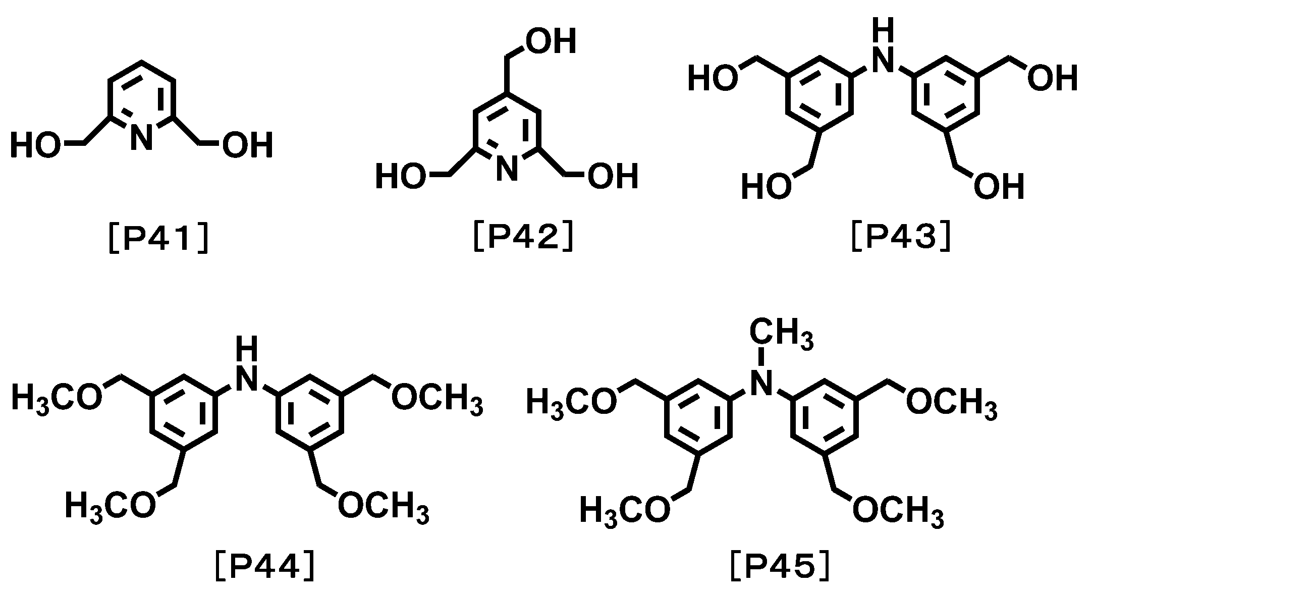
ヒドロキシル基又はアルコキシル基からなる群より選ばれる少なくとも1種の置換基を有する架橋性化合物としては、例えば、ヒドロキシル基又はアルコキシル基を有するアミノ樹脂、例えばメラミン樹脂、尿素樹脂、グアナミン樹脂、グリコールウリル-ホルムアルデヒド樹脂、スクシニルアミド-ホルムアルデヒド樹脂、エチレン尿素-ホルムアルデヒド樹脂などが挙げられる。
この架橋性化合物は、例えば、アミノ基の水素原子がメチロール基又はアルコキシメチル基又はその両方で置換されたメラミン誘導体、ベンゾグアナミン誘導体又はグリコールウリルを用いることができる。このメラミン誘導体及びベンゾグアナミン誘導体は二量体又は三量体として存在することも可能である。これらはトリアジン環1個当たり、メチロール基又はアルコキシメチル基を平均3個以上6個以下有するものが好ましい。
このようなメラミン誘導体又はベンゾグアナミン誘導体の例としては、市販品のトリアジン環1個当たりメトキシメチル基が平均3.7個置換されているMX-750、トリアジン環1個当たりメトキシメチル基が平均5.8個置換されているMW-30(以上、三和ケミカル製)や、サイメル300、301、303、350、370、771、325、327、703、712などのメトキシメチル化メラミン、サイメル235、236、238、212、253、254などのメトキシメチル化ブトキシメチル化メラミン、サイメル506、508などのブトキシメチル化メラミン、サイメル1141のようなカルボキシル基含有メトキシメチル化イソブトキシメチル化メラミン、サイメル1123のようなメトキシメチル化エトキシメチル化ベンゾグアナミン、サイメル1123-10のようなメトキシメチル化ブトキシメチル化ベンゾグアナミン、サイメル1128のようなブトキシメチル化ベンゾグアナミン、サイメル1125-80のようなカルボキシル基含有メトキシメチル化エトキシメチル化ベンゾグアナミン(以上、三井サイアナミド製)が挙げられる。また、グリコールウリルの例として、サイメル1170のようなブトキシメチル化グリコールウリル、サイメル1172のようなメチロール化グリコールウリル等、パウダーリンク1174のようなメトキシメチロール化グリコールウリル等が挙げられる。
エポキシ基又はイソシアネート基を有する架橋性化合物としては、例えばビスフェノールアセトングリシジルエーテル、フェノールノボラックエポキシ樹脂、クレゾールノボラックエポキシ樹脂、トリグリシジルイソシアヌレート、テトラグリシジルアミノジフェニレン、テトラグリシジル-m-キシレンジアミン、テトラグリシジル-1,3-ビス(アミノエチル)シクロヘキサン、テトラフェニルグリシジルエーテルエタン、トリフェニルグリシジルエーテルエタン、ビスフェノールヘキサフルオロアセトジグリシジルエーテル、1,3-ビス(1-(2,3-エポキシプロポキシ)-1-トリフルオロメチル-2,2,2-トリフルオロメチル)ベンゼン、4,4-ビス(2,3-エポキシプロポキシ)オクタフルオロビフェニル、トリグリシジル-p-アミノフェノール、テトラグリシジルメタキシレンジアミン、2-(4-(2,3-エポキシプロポキシ)フェニル)-2-(4-(1,1-ビス(4-(2,3-エポキシプロポキシ)フェニル)エチル)フェニル)プロパン、1,3-ビス(4-(1-(4-(2,3-エポキシプロポキシ)フェニル)-1-(4-(1-(4-(2,3-エポキシプロポキシフェニル)-1-メチルエチル)フェニル)エチル)フェノキシ)-2-プロパノール等が挙げられる。エポキシ基を2つ以上含有する化合物としては、具体的には、以下のような化合物が例示される。

オキセタン基を有する架橋性化合物としては、下記の式[4]で示すオキセタン基を少なくとも2個有する架橋性化合物である。

具体的には、下記の式[4a]~式[4k]で示される架橋性化合物である。

ブロックイソシアネート基を2つ以上含有する化合物としては、下記式(5)で表されるブロックイソシアネート基を有する化合物が例示される。

Zはそれぞれ独立して、炭素数1~3のアルキル基、水酸基又は下記式(6)で表される有機基であり、Zの少なくとも1つは、下記式(6)で表される有機基である。

具体的には、以下のような化合物が例示される。

上記式(7)以外のブロックイソシアネート基を2つ以上含有する化合物は、以下のような化合物が例示される。

オキサゾリン化合物としては、2,2’-ビス(2-オキサゾリン)、1,2,4-トリス-(2-オキサゾリニル-2)-ベンゼン、4-フラン-2-イルメチレン-2-フェニル-4H-オキサゾール-5-オン、1,4-ビス(4,5-ジヒドロ-2-オキサゾリル)ベンゼン、1,3-ビス(4,5-ジヒドロ-2-オキサゾリル)ベンゼン、2,3-ビス(4-イソプロペニル-2-オキサゾリン-2-イル)ブタン、2,2’-ビス-4-ベンジル-2-オキサゾリン、2,6-ビス(イソプロピル-2-オキサゾリン-2-イル)ピリジン、2,2’-イソプロピリデンビス(4-tert-ブチル-2-オキサゾリン)、2,2’-イソプロピリデンビス(4-フェニル-2-オキサゾリン)、2,2’-メチレンビス(4-tert-ブチル-2-オキサゾリン)、及び2,2’-メチレンビス(4-フェニル-2-オキサゾリン)が挙げられる。これらの他、エポクロス(商品名、株式会社日本触媒製)のようなオキサゾリルを有するポリマーやオリゴマーも挙げることができる。
プリミド系架橋剤とは、ヒドロキシアルキルアミド基を有する化合物である。(B)成分は、ヒドロキシアルキルアミド基を有していれば、その他の構造は特に限定されないが、入手性等の点から、好ましい例として、下記式(2)で表される化合物が挙げられる。

X2は炭素数1~20の脂肪族炭化水素基、又は芳香族炭化水素基を含むn価の有機基である。nは2~6の整数である。
中でも、式(2)のX2中の、カルボニル基に直接結合する原子は、芳香環を形成していない炭素原子であることが液晶配向性の観点から好ましい。また、式(2)のX2は、液晶配向性及び溶解性の観点から、脂肪族炭化水素基であることが好ましく、炭素数1~10であることがより好ましい。
式(2)中、nは、溶解性の観点から、2~4が好ましい。

式(3)中、R4~R7は、それぞれ独立して、水素原子、炭化水素基、又はヒドロキシ基で置換された炭化水素基である。

これらの架橋性添加剤は、1種類が添加されていても良いが、本発明の特性を損ねない程度において、複数種添加されていても良い。
好ましい添加量は0.1重量%~30重量%であり、好ましくは0.5重量%~10重量%である。
重合性不飽和結合を有する架橋性化合物としては、トリメチロールプロパントリ(メタ)アクリレート、ペンタエリスリトールトリ(メタ)アクリレート、ジペンタエリスリトールペンタ(メタ)アクリレート、トリ(メタ)アクリロイルオキシエトキシトリメチロールプロパン、グリセリンポリグリシジルエーテルポリ(メタ)アクリレート等の重合性不飽和基を分子内に3個有する架橋性化合物、さらに、エチレングリコールジ(メタ)アクリレート、ジエチレングリコールジ(メタ)アクリレート、テトラエチレングリコールジ(メタ)アクリレート、ポリエチレングリコールジ(メタ)アクリレート、プロピレングリコールジ(メタ)アクリレート、ポリプロピレングリコールジ(メタ)アクリレート、ブチレングリコールジ(メタ)アクリレート、ネオペンチルグリコールジ(メタ)アクリレート、エチレンオキサイドビスフェノールA型ジ(メタ)アクリレート、プロピレンオキサイドビスフェノール型ジ(メタ)アクリレート、1,6-へキサンジオールジ(メタ)アクリレート、グリセリンジ(メタ)アクリレート、ペンタエリスリトールジ(メタ)アクリレート、エチレングリコールジグリシジルエーテルジ(メタ)アクリレート、ジエチレングリコールジグリシジルエーテルジ(メタ)アクリレート、フタル酸ジグリシジルエステルジ(メタ)アクリレート、ヒドロキシピバリン酸ネオペンチルグリコールジ(メタ)アクリレート等の重合性不飽和基を分子内に2個有する架橋性化合物、加えて、2-ヒドロキシエチル(メタ)アクリレート、2-ヒドロキシプロピル(メタ)アクリレート、2-ヒドロキシブチル(メタ)アクリレート、2-フェノキシ-2-ヒドロキシプロピル(メタ)アクリレート、2-(メタ)アクリロイルオキシ-2-ヒドロキシプロピルフタレート、3-クロロ-2-ヒドロキシプロピル(メタ)アクリレート、グリセリンモノ(メタ)アクリレート、2-(メタ)アクリロイルオキシエチルリン酸エステル、N-メチロール(メタ)アクリルアミド等の重合性不飽和基を分子内に1個有する架橋性化合物が挙げられる。
加えて、下記の式[5]で示される化合物を用いることもできる。

(式[5]中、A1は、シクロヘキシル環、ビシクロヘキシル環、ベンゼン環、ビフェニル環、ターフェニル環、ナフタレン環、フルオレン環、アントラセン環、又はフェナントレン環から選ばれる基であり、A2は、下記の式[5a]、又は式[5b]から選ばれる基であり、nは1~4の整数である)。

上記化合物は架橋性化合物の一例であり、これらに限定されるものではない。また、本発明の液晶配向処理剤に含有される架橋性化合物は、1種類であってもよく、2種類以上組み合わせてもよい。
チイラン化合物としては、フェニルグリシジルエーテル、ブチルグリシジルエーテル、3,3,3-トリフルオロメチルプロピレンオキシド、スチレンオキシド、ヘキサフルオロプロピレンオキシド、シクロヘキセンオキシド、N-グリシジルフタルイミド、(ノナフルオロ-N-ブチル)エポキシド、パーフルオロエチルグリシジルエーテル、エピクロロヒドリン、エピブロモヒドリン、N,N-ジグリシジルアニリン、及び3-[2-(パーフルオロヘキシル)エトキシ]-1,2-エポキシプロパン、エチレングリコールジグリシジルエーテル、ポリエチレングリコールジグリシジルエーテル、プロピレングリコールジグリシジルエーテル、トリプロピレングリコールジグリシジルエーテル、ポリプロピレングリコールジグリシジルエーテル、ネオペンチルグリコールジグリシジルエーテル、1,6-ヘキサンジオールジグリシジルエーテル、グリセリンジグリシジルエーテル、2,2-ジブロモネオペンチルグリコールジグリシジルエーテル、及び3-(N,N-ジグリシジル)アミノプロピルトリメトキシシラン、1,3,5,6-テトラグリシジル-2,4-ヘキサンジオール、N,N,N’,N’-テトラグリシジル-m-キシレンジアミン、1,3-ビス(N,N-ジグリシジルアミノメチル)シクロヘキサン、N,N,N’,N’,-テトラグリシジル-4,4’-ジアミノジフェニルメタン、及び3-(N-アリル-N-グリシジル)アミノプロピルトリメトキシシランにおけるグリシジル基の酸素を、例えばJ.Org.Chem.,28,229(1963)に記載されている方法に従って硫黄に置換し、前記グリシジル基をエチレンスルフィド基に変換したもの、が挙げられる。
アジリジン化合物としては、2,4,6-トリス(1’-アジリジニル)-1,3,5-トリアジン、ω-アジリジニルプロピオン酸-2,2-ジヒドロキシメチル-ブタノールトリエステル、2,4,6-トリス(2-メチル-1-アジリジニル)-1,3,5-トリアジン、2,4,6-トリス(2-エチル-1-アジリジニル)-1,3,5-トリアジン、4,4’-ビス(エチレンイミノカルボニルアミノ)ジフェニルメタン、ビス(2-エチル-1-アジリジニル)ベンゼン-1,3-ジカルボン酸アミド、トリス(2-エチル-1-アジリジニル)ベンゼン-1,3,5-トリカルボン酸アミド、ビス(2-エチル-1-アジリジニル)セバシン酸アミド、1,6-ビス(エチレンイミノカルボニルアミノ)ヘキサン、2,4-ジエチレンウレイドトルエン、1,1’-カルボニル-ビス-エチレンイミン、ポリメチレン-ビス-エチレンユリア(C2~C4)、及びN,N’-ビス(4,6-ジエチレンイミノ-1,3,5-トリアジン-2-イル)-ヘキサメチレンジアミンが挙げられる。これらの他、アジリジニルを有するオリゴマーやポリマーも挙げることができる。
本発明に用いられる液晶構造体安定化剤は、上記の重合体成分及び架橋性添加剤以外の成分を含有してもよい。その例としては、液晶構造体安定化剤を塗布した際の膜厚均一性や表面平滑性を向上させる溶媒や化合物、液晶構造体安定化膜と基板との密着性を向上させる化合物などである。
例えば、イソプロピルアルコール、メトキシメチルペンタノール、メチルセロソルブ、エチルセロソルブ、ブチルセロソルブ、メチルセロソルブアセテート、エチルセロソルブアセテート、ブチルカルビトール、エチルカルビトール、エチルカルビトールアセテート、エチレングリコール、エチレングリコールモノアセテート、エチレングリコールモノイソプロピルエーテル、エチレングリコールモノブチルエーテル、プロピレングリコール、プロピレングリコールモノブチルエーテル、プロピレングリコールモノアセテート、プロピレングリコールモノメチルエーテル、プロピレングリコール-tert-ブチルエーテル、ジプロピレングリコールモノメチルエーテル、ジエチレングリコール、ジエチレングリコールモノアセテート、ジエチレングリコールジメチルエーテル、ジプロピレングリコールモノアセテートモノメチルエーテル、ジプロピレングリコールモノメチルエーテル、ジプロピレングリコールモノエチルエーテル、ジプロピレングリコールモノアセテートモノエチルエーテル、ジプロピレングリコールモノプロピルエーテル、ジプロピレングリコールモノアセテートモノプロピルエーテル、3-メチル-3-メトキシブチルアセテート、トリプロピレングリコールメチルエーテル、3-メチル-3-メトキシブタノール、ジイソプロピルエーテル、エチルイソブチルエーテル、ジイソブチレン、アミルアセテート、ブチルブチレート、ブチルエーテル、ジイソブチルケトン、メチルシクロへキセン、プロピルエーテル、ジヘキシルエーテル、1-ヘキサノール、n-へキサン、n-ペンタン、n-オクタン、ジエチルエーテル、乳酸メチル、乳酸エチル、酢酸メチル、酢酸エチル、酢酸n-ブチル、酢酸プロピレングリコールモノエチルエーテル、ピルビン酸メチル、ピルビン酸エチル、3-メトキシプロピオン酸メチル、3-エトキシプロピオン酸メチルエチル、3-メトキシプロピオン酸エチル、3-エトキシプロピオン酸、3-メトキシプロピオン酸、3-メトキシプロピオン酸プロピル、3-メトキシプロピオン酸ブチル、1-メトキシ-2-プロパノール、1-エトキシ-2-プロパノール、1-ブトキシ-2-プロパノール、1-フェノキシ-2-プロパノール、プロピレングリコールモノアセテート、プロピレングリコールジアセテート、プロピレングリコール-1-モノメチルエーテル-2-アセテート、プロピレングリコール-1-モノエチルエーテル-2-アセテート、ジプロピレングリコール、2-(2-エトキシプロポキシ)プロパノール、乳酸メチルエステル、乳酸エチルエステル、乳酸n-プロピルエステル、乳酸n-ブチルエステル、乳酸イソアミルエステルなどの低表面張力を有する溶媒などが挙げられる。
これらの貧溶媒は1種類でも複数種類を混合して用いてもよい。上記のような溶媒を用いる場合は、液晶構造体安定化剤に含まれる溶媒全体の5~80質量%であることが好ましく、より好ましくは20~60質量%である。
より具体的には、例えば、エフトップEF301、EF303、EF352(トーケムプロダクツ社製))、メガファックF171、F173、R-30(大日本インキ社製)、フロラードFC430、FC431(住友スリーエム社製)、アサヒガードAG710、サーフロンS-382、SC101、SC102、SC103、SC104、SC105、SC106(旭硝子社製)などが挙げられる。これらの界面活性剤の使用割合は、液晶構造体安定化剤に含有される重合体成分の100質量部に対して、好ましくは0.01~2質量部、より好ましくは0.01~1質量部である。
例えば、3-アミノプロピルトリメトキシシラン、3-アミノプロピルトリエトキシシラン、2-アミノプロピルトリメトキシシラン、2-アミノプロピルトリエトキシシラン、N-(2-アミノエチル)-3-アミノプロピルトリメトキシシラン、N-(2-アミノエチル)-3-アミノプロピルメチルジメトキシシラン、3-ウレイドプロピルトリメトキシシラン、3-ウレイドプロピルトリエトキシシラン、N-エトキシカルボニル-3-アミノプロピルトリメトキシシラン、N-エトキシカルボニル-3-アミノプロピルトリエトキシシラン、N-トリエトキシシリルプロピルトリエチレントリアミン、N-トリメトキシシリルプロピルトリエチレントリアミン、10-トリメトキシシリル-1,4,7-トリアザデカン、10-トリエトキシシリル-1,4,7-トリアザデカン、9-トリメトキシシリル-3,6-ジアザノニルアセテート、9-トリエトキシシリル-3,6-ジアザノニルアセテート、N-ベンジル-3-アミノプロピルトリメトキシシラン、N-ベンジル-3-アミノプロピルトリエトキシシラン、N-フェニル-3-アミノプロピルトリメトキシシラン、N-フェニル-3-アミノプロピルトリエトキシシラン、N-ビス(オキシエチレン)-3-アミノプロピルトリメトキシシラン、N-ビス(オキシエチレン)-3-アミノプロピルトリエトキシシラン、エチレングリコールジグリシジルエーテル、ポリエチレングリコールジグリシジルエーテル、プロピレングリコールジグリシジルエーテル、トリプロピレングリコールジグリシジルエーテル、ポリプロピレングリコールジグリシジルエーテル、ネオペンチルグリコールジグリシジルエーテル、1,6-ヘキサンジオールジグリシジルエーテル、グリセリンジグリシジルエーテル、2,2-ジブロモネオペンチルグリコールジグリシジルエーテル、1,3,5,6-テトラグリシジル-2,4-ヘキサンジオール、N,N,N’,N’-テトラグリシジル-m-キシレンジアミン、1,3-ビス(N,N-ジグリシジルアミノメチル)シクロヘキサン、N,N,N’,N’-テトラグリシジル-4、4’-ジアミノジフェニルメタンなどが挙げられる。
基板との密着性を向上させる化合物を使用する場合、その使用量は、液晶構造体安定化剤に含有される重合体成分の100質量部に対して0.1~30質量部であることが好ましく、より好ましくは1~20質量部である。使用量が0.1質量部未満であると密着性向上の効果は期待できず、30質量部よりも多くなると液晶配向性が悪くなる場合がある。
本発明に用いる液晶構造体安定化剤は、上記の重合体と添加物を有機溶媒に溶解した形態で含有する。液晶構造体安定化剤には上記の重合体が、好ましくは1~15質量%、より好ましくは2~10質量%、さらに好ましくは2~8質量%含有される。なお、本発明の液晶構造体安定化剤には、本発明の効果を損なわない限りにおいて、上記の重合体以外のポリアミック酸、ポリアミック酸エステル、それらをイミド化したポリイミド及びその他の重合体(以上、これらを「他の重合体」とも称する)が含まれていても構わない。
本発明の液晶構造体安定化剤中において、他の重合体が含有される場合は、上記重合体100質量部に対して、好ましくは10~1000質量部、より好ましくは10~800質量部含有されることがある。
本発明に用いられる液晶構造体安定化剤において、各重合体を溶解するのに使用される有機溶媒としては、重合体成分を溶解させる有機溶媒であれば特に限定されない。その具体例を以下に挙げる。
N,N-ジメチルホルムアミド、N,N-ジメチルアセトアミド、N-メチル-2-ピロリドン、N-メチルカプロラクタム、2-ピロリドン、N-エチルピロリドン、N-ビニルピロリドン、ジメチルスルホキシド、テトラメチル尿素、ピリジン、ジメチルスルホン、γ-ブチロラクトン、3-メトキシ-N,N-ジメチルプロパンアミド、3-エトキシ-N,N-ジメチルプロパンアミド、3-ブトキシ-N,N-ジメチルプロパンアミド、1,3-ジメチル-イミダゾリジノン、エチルアミルケトン、メチルノニルケトン、メチルエチルケトン、メチルイソアミルケトン、メチルイソプロピルケトン、シクロヘキサノン、エチレンカーボネート、プロピレンカーボネート、ジグライム、4-ヒドロキシ-4-メチル-2-ペンタノンなどが挙げられる。これらは単独で使用しても、混合して使用してもよい。
本発明の液晶構造体安定化膜を用いて形成される液晶表示素子は、例えば以下のようにして製造することができる。
先ず、上記のようにして液晶構造体安定化膜が形成された一対の基板を準備し、この一対の基板間に液晶が狭持された構成の液晶セルを製造する。液晶セルを製造するには、例えば以下の2つの方法が挙げられる。
第一の方法は、従来から知られている方法である。先ず、それぞれの液晶構造体安定化膜が対向するように間隙(セルギャップ)を介して2枚の基板を対向配置し、2枚の基板の周辺部をシール剤を用いて貼り合わせ、基板表面およびシール剤により区画されたセルギャップ内に液晶を注入充填した後、注入孔を封止することにより、液晶セルを製造することができる。
セルギャップを得る方法としては、特に限定しないが、スペーサービーズ(酸化アルミニウム球)等を液晶構造体安定化膜を設けた基板上に均等に散布した後張り合わせる方法や、散布せずにシール剤中にスペーサービーズを分散させて塗布・張り合わせすることによりセルギャップを設ける方法、あらかじめフォトレジスト等を用いて特定のセルギャップになるように構造物を設けた基板を用いる等が挙げられる。
ULHの配向は異物等の影響を強く受けるため、画素内にスペーサービーズが無いような状態が好ましい。よって好ましくはスペーサービーズをシール剤に分散させてセルギャップを確保する方法、あらかじめフォトレジスト等を用いて特定のセルギャップになるように構造物を設けた基板を用いるのが好ましい。
第二の方法は、ODF(One Drop Fill)方式と呼ばれる手法である。液晶構造体安定化膜を形成した2枚の基板のうちの一方の基板上の所定の場所に例えば紫外光硬化性のシール剤を塗布し、さらに液晶配向膜面上に液晶を滴下した後、液晶構造体安定化膜が対向するように他方の基板を貼り合わせ、次いで基板の全面に紫外光を照射してシール剤を硬化することにより、液晶セルを製造することができる。
前記シール剤としては、例えば硬化剤を含有するエポキシ樹脂等を用いることができる。
いずれの方法による場合でも、次いで、液晶セルを、用いた液晶が等方相をとる温度まで加熱した後、室温まで徐冷することにより、液晶充填時の流動配向を除去することが望ましい。
ULH配向モードに使用される液晶はコレステリック液晶であるが、より安定なULH配向を得るには強いフレキソエレクトリック効果の得られる液晶を用いる必要がある。フレキソエレクトリック効果が得られる液晶としては以下のようなバイメソゲンタイプの液晶が挙げられ、これらの構造を含有するコレステリック液晶を使用することでULH配向を得ることができるが、これに限定されない。

(式中、X1、X2はそれぞれ独立して単結合、エステル結合、エーテル結合から選ばれる連結基を表し、Lは6~20で表される整数である。)
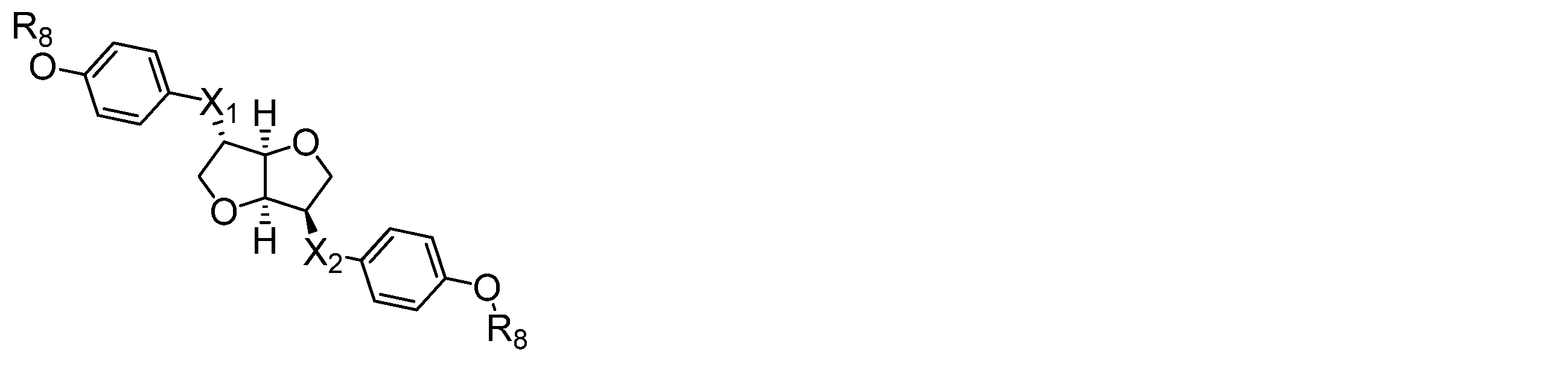
(式中、X1、X2はそれぞれ独立して単結合、エステル結合、エーテル結合から選ばれる連結基を表し、R8は3~10のアルキル基を表す。)
上記コレステリック液晶を、上記配向膜を設けた液晶セル中に注入し、加熱処理とともに電界を印加することによりULH配向へ転移させることができる。例えば、用いた液晶の等方相になる温度に昇温させ、完全に等方相に変わったのを確認し、電圧を液晶セルに印加しながらゆっくり室温に戻すことでULH配向に誘導することができる。
セルギャップや用いる液晶の種類によって条件が変わるため、好ましい温度降下速度や印加電圧の種類や強度は限定することができないが、等方相になる温度からの温度降下速度は好ましくは毎分1~30℃、好ましくは1~10℃であり、印加する電圧は1~10V/μm、好ましくは2~8/μmの電界強度の矩形波交流が好ましく、周波数は1~1KHz、より好ましくは10~300Hzが好ましい。
そして、液晶セルの外側表面に偏光板を貼り合わせることにより、所望の液晶表示素子を得ることができる。ここで、液晶構造体安定化膜が形成された2枚の基板における、照射した直線偏光放射線の偏光方向のなす角度およびそれぞれの基板と偏光板との角度を適当に調整することにより、所望の液晶表示素子を得ることができる。
液晶セルの外側に使用される偏光板としては、ポリビニルアルコールを延伸配向させながらヨウ素を吸収させた「H膜」と呼ばれる偏光膜を酢酸セルロース保護膜で挟んだ偏光板、またはH膜そのものからなる偏光板等を挙げることができる。
4.1.略号
実施例及び比較例で使用する化合物の略号は以下の通りである。MWは分子量を表す。
<テトラカルボン酸二無水物>
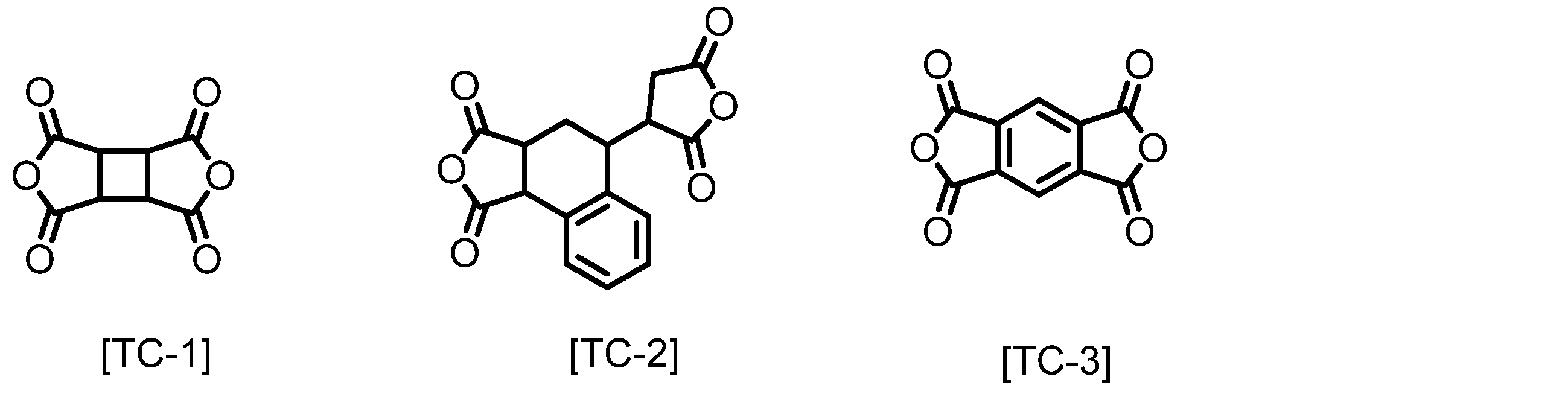
TC-1:1,2,3,4-シクロブタンテトラカルボン酸二無水物 (MW196)
TC-2:3,4-ジカルボキシ-1,2,3,4-テトラヒドロ-1-ナフタレンコハク酸二無水物
TC-3:ピロメリット酸二無水物
<ジアミン>
DA-1:1,4-フェニレンジアミン
DA-2:B-3:4,4-ジアミノジフェニルメタン
DA-3:4-アミノベンジルアミン
DA-4:3-アミノベンジルアミン
DA-5:N,N-ジアリルアミノ-2,4-ジアミノベンゼン
DA-6:2-ドデシルオキシ-2,4-ジアミノベンゼン
DA-7:4-(トランス-4-ペンチルシクロヘキシル)ベンズアミド‐2’,4’-フェニレンジアミン
DA-8:2-オクタデシルオキシ-2,4-ジアミノベンゼン
DA-9:1,5-ビス(4-アミノフェノキシ)ヘプタン

<架橋性添加剤>
Ad-1:ビス-(3,5-ビス-ヒドロキシメチル-4-ヒドロキシフェニル)ジメチルメタン

<有機溶媒>
NMP:N-メチル-2-ピロリドン
GBL:γ-ブチロラクトン
BCS:ブチルセロソルブ
実施した液晶構造体安定化剤の評価方法は以下のとおりである。
<粘度測定>
ポリアミック酸溶液の粘度は、E型粘度計TVE-22H(東機産業社製)を用い、サンプル量1.1mL、コーンロータTE-1(1°34’、R24)、温度25℃で測定した。
<イミド化率の測定>
ポリイミドのイミド化率は次のようにして測定した。
ポリイミド粉末20mgをNMRサンプル管に入れ、重水素化ジメチルスルホキシド(DMSO-d6、0.05%TMS混合品)0.53mlを添加し、完全に溶解させた。この溶液を日本電子データム社製NMR測定器(JNM-ECA500)にて500MHzのプロトンNMRを測定した。
イミド化率は、以下の式によって算出した。なお、式(1)で表されるジアミンを用いないポリイミドのイミド化率は、下記の式中の「ポリアミック酸重合時の式(1)ジアミンの導入量」の値をゼロとして算出した。
イミド化率(%)=(100-ポリアミック酸重合時の式(1)ジアミンの導入量(mol%)/2)×α
式中αは、イミド化前後で変化しない構造に由来するプロトンを基準プロトンとして決め、このプロトンのピーク積算値と、9.5~10.0ppm付近に現れるアミック酸のNH基に由来するプロトンピーク積算値とを用い、次式によって求めた。
α=(1-α・x/y)
上記式において、xはアミック酸のNH基由来のプロトンピーク積算値、yは基準プロトンのピーク積算値、αはポリアミック酸(イミド化率が0%)の場合におけるアミック酸のNH基プロトン一個に対する基準プロトンの個数割合である。
実施例1
合成例1
窒素導入管と撹拌子を備えた300mlの4口フラスコに、DA-1(4.87g:45.00mmol)とDA-8(1.88g:5.00mmol)を測り取り、NMPを122.5g加え、窒素雰囲気下で撹拌し、完全に溶解させた。溶液を10℃以下に冷却し、TC-2(14.86g:49.50mmol)を加え、30分撹拌した後、40℃に昇温し、窒素雰囲気下で24時間反応させ、ポリアミック酸溶液(以下PAA-1)を得た。
500mlの三角フラスコに 得られたPAA-1を100g測り取り、NMPを130.77g、無水酢酸(35.43g:347.00mmol)、ピリジン(16.48g:208.20mmol)の順に加え、室温で30分撹拌後、45℃で3時間反応させた。反応終了後、冷却した1000mlのメタノール中に反応溶液を撹拌しながら注ぎ、固体を析出させた。得られた固体をろ過により回収し、更にメタノール500mlを用いて2回撹拌洗浄した後、100℃にて真空乾燥させ、白色の固体として可溶性ポリイミド(SPI-1)を得た。得られたポリイミドのイミド化率は87%、重量平均分子量は32000であった。
撹拌子を備えた300mlの三角フラスコに、上記の操作にて得られたSPI-1を5.00g測り取り、GBL45.00gを加え、50℃で16時間撹拌し、完全に溶解させた。この溶液にNMP16.67g、BCS16.67g、Ad-1(0.50g:SPI-1に対し10質量%分)を加え、室温で24時間撹拌し、本発明に使用する液晶構造体安定化剤(以下AL-1)を得た。
合成例2
窒素導入管と撹拌子を備えた200mlの4口フラスコにDA-3(2.93g:24.00mmol)、DA-5(6.50g:32.00mmol)、DA-6(7.02g:24.00mmol)をそれぞれ測り取り、NMP129.70gを加え、窒素雰囲気下で撹拌し、完全に溶解させた。この溶液を10℃以下に冷却し、TC-3(5.23g:24.00mmol)を加え、30分撹拌し反応させた後、TC-1(10.75g:54.80mmol)を加え、室温に戻し窒素雰囲気下で24時間反応させポリアミック酸溶液(以下PAA-2)を得た。
撹拌子を備えた300mlの三角フラスコに、上記で得られたPAA-2を150.0g測り取り、NMP185.7g加え希釈し、無水酢酸(23.30g:228.3mmol)、ピリジン(10.00g:126.37mmol)を加え、室温で30分撹拌した後、50℃に昇温し3時間反応させた。反応終了後、冷却した1000mlのメタノール中に反応溶液を撹拌しながら注ぎ、固体を析出させた。得られた固体をろ過により回収し、更にメタノール500mlを用いて2回撹拌洗浄した後、100℃にて真空乾燥させ、オレンジ色の固体として可溶性ポリイミド(SPI-2)を得た。得られたポリイミドのイミド化率は85%、重量平均分子量は37000であった。
撹拌子を備えた300mlの三角フラスコに、上記の操作にて得られたSPI-2を5.00g測り取り、GBL45.00gを加え、50℃で16時間撹拌し、完全に溶解させた。この溶液にNMP16.67g、BCS16.67g、Ad-1(0.50g:SPI-2に対し10質量%分)を加え、室温で24時間撹拌し、本発明に使用する液晶構造体安定化剤(以下AL-2)を得た。
合成例3
窒素導入管と撹拌子を備えた200mlの4口フラスコにDA-4(1.95g:16.00mmol)、DA-5(8.13g:40.00mmol)、DA-7(9.78g:24.00g)をそれぞれ測り取り、NMP143.00gを加え、窒素雰囲気下50℃で撹拌し、完全に溶解させた。この溶液に、TC-3(2.62g:12.00mmol)を加え、30分撹拌し反応させた後、TC-1(13.26g:67.60mmol)を加え、室温に戻し、窒素雰囲気下で24時間反応させ、ポリアミック酸溶液(以下PAA-3)を得た。
撹拌子を備えた300mlの三角フラスコに、上記で得られたPAA-3を150.0g測り取り、NMP278.6g加え希釈し、無水酢酸(20.78g:203.50mmol)、ピリジン(8.91g:112.61mmol)を加え、室温で30分撹拌した後、50℃に昇温し、3時間反応させた。反応終了後、冷却した1000mlのメタノール中に反応溶液を撹拌しながら注ぎ、固体を析出させた。得られた固体をろ過により回収し、更にメタノール500mlを用いて2回撹拌洗浄した後、100℃にて真空乾燥させ、オレンジ色の固体として可溶性ポリイミド(SPI-3)を得た。得られたポリイミドのイミド化率は83%、重量平均分子量は32000であった。
撹拌子を備えた300mlの三角フラスコに、上記の操作にて得られたSPI-3を5.00g測り取り、GBL45.00gを加え、50℃で16時間撹拌し、完全に溶解させた。この溶液にNMP16.67g、BCS16.67g、Ad-1(0.50g:SPI-3に対し10質量%分)を加え、室温で24時間撹拌し、本発明に使用する液晶構造体安定化剤(以下AL-3)を得た。
撹拌子を備えた100ml三角フラスコに、実施例2と実施例3で得られたAL-2(25.0g)とAL-3(25.0g)を測り取り、室温で24時間撹拌し、本発明に使用する液晶構造体安定化剤(以下AL-4)を得た。
合成例4
窒素導入管と撹拌子を備えた200mlの4口フラスコにDA-8(1.13g:3.00mmol)、DA-9(7.73g:27.00mmol)をそれぞれ測り取り、NMP109.60g加え、窒素雰囲気下で完全に溶解させた。この溶液を10℃以下に冷却し、TC-3(6.09g:27.9mmol)を加え、室温に戻し、窒素雰囲気下で24時間反応させ、ポリアミック酸溶液(以下PAA-4)を得た。得られたPAA-4の重量平均分子量は31700であった。
撹拌子を備えた300mlの三角フラスコに上記で得られたPAA-4を100g測り取り、NMPを40.00g、BCSを60.00g、Ad-1(1.20g:PAA-4固形分の10質量%)を加え、室温で24時間撹拌し、液晶構造体安定化剤(以下AL-5)を得た。
合成例5
窒素導入管と撹拌子を備えた200mlの4口フラスコにDA-2(11.76g:59.3mmol)を測り取り、NMP65.80g、GBL65.80gを加え、窒素雰囲気下で完全に溶解させた。この溶液を10℃以下に冷却し、TC-3(6.47g:29.65mmol)を加え、30分撹拌し、反応させた後、TC-1(5.00g:25.50mmol)を加え、室温に戻し、窒素雰囲気下で24時間反応させ、ポリアミック酸溶液(以下PAA-5)を得た。得られたPAA-5の重量平均分子量は29000であった。
撹拌子を備えた300mlの三角フラスコに上記で得られたPAA-5を100g測り取り、GBLを112.50g、BCSを37.50g加え、室温で24時間撹拌し、液晶構造体安定化剤(以下AL-6)を得た。
合成例1の手順で得られる液晶構造体安定化剤において、Ad-1を未添加のものを調製し、比較対象とする液晶構造体安定化剤AL-7を得た。
撹拌子を備えた100ml三角フラスコに、実施例1で得られたAL-1(20.0g)と実施例4で得られたAL-4(80.0g)を測り取り、室温で24時間撹拌し、比較対象となる液晶構造体安定化剤(以下AL-8)を得た。

<液晶構造体安定化膜のラフネス測定>
液晶構造体安定化剤を1.0μmのフィルターで濾過した後、電極付き基板(横30mm×縦40mmの大きさで、厚さが1.1mmのガラス基板。電極は幅10mm×長さ40mmの矩形で、厚さ35nmのITO電極)に、スピンコート塗布にて塗布した。スピンコート後、室温23℃、湿度50%下で5分間放置し、220℃のIRオーブンで20分間焼成させて液晶構造体安定化膜付き基板を得た。この液晶構造体安定化膜をレーヨン布(吉川化工製YA-20R)でラビング(ローラー直径:120mm、ローラー回転数:700rpm、移動速度:50mm/sec、押し込み長:0.2mm)した後、純水中にて1分間超音波照射をして洗浄を行い、エアブローにて水滴を除去した後、80℃で15分間乾燥して液晶構造体安定化膜付き基板を得た。得られた膜の均一性をDFM(ダイレクトフォース原子間力顕微鏡:日立ハイテク製)を用いて表面分析し、10μmあたりのラフネスを算出し比較を行った。ラフネスが小さいほど膜の均一性や成膜性が良好であることを意味する。
<液晶構造体安定化膜付き基板の作成>
液晶構造体安定化剤を1.0μmのフィルターで濾過した後、電極付き基板(横30mm×縦40mmの大きさで、厚さが1.1mmのガラス基板。電極は幅10mm×長さ40mmの矩形で、厚さ35nmのITO電極)に、スピンコート塗布にて塗布した。80℃のホットプレート上で1分間乾燥させた後、220℃のIR式オーブンで20分間焼成を行い、膜厚100nmの塗膜を形成させて液晶構造体安定化膜付き基板を得た。この液晶構造体安定化膜をレーヨン布(吉川化工製YA-20R)でラビング(ローラー直径:120mm、ローラー回転数:700rpm、移動速度:50mm/sec、押し込み長:0.2mm)した後、純水中にて1分間超音波照射をして洗浄を行い、エアブローにて水滴を除去した後、80℃で15分間乾燥して液晶構造体安定化膜付き基板を得た。
上記の液晶構造体安定化膜付き基板を2枚用意し、一方の基板の液晶構造体安定化膜上に6.0μmまたは4.0μmのビーズスペーサーを混合したシール剤(協立化学製XN-1500T)をディスペンサーを用いて塗布し、次いで、もう一方の基板を、液晶構造体安定化膜面が向き合い、配向方向が0°になるようにして張り合わせた後、シール剤を熱硬化させて空セルを作製した。
前記の様にして得た空セルを80℃に加熱したホットプレート上に載せ、メルク社製のULHモード用液晶を用い、キャピラリー注入にて液晶を注入し、液晶の注入口を封止してULH評価用のセルを作成した。その模式図を図1に示す。
<ULH初期配向の観察>
加熱冷却可能なステージがついた偏光顕微鏡(POM)を用いて配向性の評価を行った。加熱冷却ステージに、前記の様にして得られた液晶セルを取り付け、液晶が等方相になる温度まで上昇させ、完全に等方相になったのを確認した後、ファンクションジェネレーターで14Vp-p(セルギャップ4.0μmの場合)または20Vp-p(セルギャップ6.0μmの場合)の矩形波交流電圧を印加しながら3℃/分の速度にて50℃まで温度を低下させるとULHへ転移させることができる。ULHの状態になったら電圧印加をやめ、室温に戻し、偏光板をクロスニコルの状態にして液晶セルを回転させ、明状態と暗状態の確認を行うことにより初期配向の評価を行った。配向性が良好な場合を図2に、不良の例を図3に、評価結果を以下に示す。
<プレチルト角測定>
また、水平配向用の液晶としてメルク社製MLC-2041を真空注入法によって注入し、液晶注入口を封止したセルを作成し、ネマティック液晶を封入したセルを用いたプレチルト角の測定を行った。測定は、Axometrix社製Axoscan ミュラーマトリクスポーラリメーターを用いて行った。

この結果から、ラビング処理後の表面ラフネスが小さく、側鎖を含有するポリイミドがULHの配向には効果的ということが判る。
Claims (14)
- 液晶構造体を安定化する膜を形成するための組成物であって、
側鎖構造を含有するポリアミック酸、側鎖構造を含有するポリアミック酸エステル、及び前記ポリアミック酸又はポリアミック酸エステルをイミド化したポリイミドからなる群から選ばれる少なくとも1種の重合体と、
ラビング耐性を向上させることのできる添加剤と
を含有する組成物。 - 前記少なくとも1種の重合体が、下記式から選ばれる少なくとも1種のジアミンを含有するジアミン成分と、テトラカルボン酸二無水物成分との反応生成物であるポリアミック酸、ポリアミック酸エステル、又は可溶性ポリイミドである、請求項1に記載の組成物。

(A1は、炭素数2~24のアルキル基もしくはフッ素含有アルキル基、又はコレステロール基を表し、A2は、-O-、-OCH2-、-CH2O-、-COOCH2-、-NHCO-、-CONH-、又は-CH2OCO-を表し、A3は炭素数1~22のアルキル基、アルコキシ基、フッ素含有アルキル基、又はフッ素含有アルコキシ基を表す。) - 前記ラビング耐性を向上させることのできる添加剤が、フェノプラスト系添加剤、アミノプラスト系添加剤、エポキシ系添加剤、アクリル系添加剤、シランカップリング剤、ブロックイソシアネート系添加剤、及びオキサゾリン系化合物からなる群より選択される、請求項1又は2に記載の組成物。
- 前記少なくとも1種の重合体が、50%~100%のイミド化率を有する可溶性ポリイミドを含む、請求項1乃至3のいずれか一項に記載の組成物。
- コレステリック液晶をULH配向させるための膜を形成するための組成物である、請求項1乃至4のいずれか一項に記載の組成物。
- 側鎖構造を含有するポリアミック酸、側鎖構造を含有するポリアミック酸エステル、及び前記ポリアミック酸又はポリアミック酸エステルをイミド化したポリイミドからなる群から選ばれる少なくとも1種の重合体と、
ラビング耐性を向上させることのできる添加剤と
を含有し、
表面平均面粗さRaが1.0nm以下である、
液晶構造体を安定化するための膜。 - ネマティック液晶を用いて測定したプレチルト角が3°~20°である、請求項6に記載の膜。
- 配向処理後の表面平均面粗さRaが1.0nm以下である、請求項6又は7に記載の膜。
- 前記配向処理が、布の摩耗が少なくなるような処理が施されたレーヨンやコットンを用いてラビング処理を行うことによる液晶の一軸配向性の付与である、請求項8に記載の膜。
- コレステリック液晶をULH配向させるための膜である、請求項6乃至9のいずれか一項に記載の膜。
- 請求項6乃至10のいずれか一項に記載の膜を有する、液晶構造体安定化膜付き基板。
- それぞれの液晶構造体安定化膜が対向するように配置された請求項11に記載の液晶構造体安定化膜付き基板の間に液晶を含む、液晶セル。
- 前記液晶がコレステリック液晶である、請求項12に記載の液晶セル。
- 偏光板、及び請求項12又は13のいずれか一項に記載の液晶セルを備えた液晶表示素子。
Priority Applications (3)
| Application Number | Priority Date | Filing Date | Title |
|---|---|---|---|
| CN201680082653.6A CN108700778B (zh) | 2015-12-25 | 2016-12-22 | 液晶表示元件、液晶光学元件和液晶结构体稳定化膜用组合物 |
| KR1020187020931A KR102803367B1 (ko) | 2015-12-25 | 2016-12-22 | 액정 표시 소자, 액정 광학 소자 및 액정 구조체 안정화막용 조성물 |
| JP2017558246A JP6981254B2 (ja) | 2015-12-25 | 2016-12-22 | 液晶表示素子、液晶光学素子及び液晶構造体安定化膜用組成物 |
Applications Claiming Priority (2)
| Application Number | Priority Date | Filing Date | Title |
|---|---|---|---|
| JP2015-255052 | 2015-12-25 | ||
| JP2015255052 | 2015-12-25 |
Publications (1)
| Publication Number | Publication Date |
|---|---|
| WO2017110976A1 true WO2017110976A1 (ja) | 2017-06-29 |
Family
ID=59089515
Family Applications (1)
| Application Number | Title | Priority Date | Filing Date |
|---|---|---|---|
| PCT/JP2016/088295 Ceased WO2017110976A1 (ja) | 2015-12-25 | 2016-12-22 | 液晶表示素子、液晶光学素子及び液晶構造体安定化膜用組成物 |
Country Status (5)
| Country | Link |
|---|---|
| JP (1) | JP6981254B2 (ja) |
| KR (1) | KR102803367B1 (ja) |
| CN (1) | CN108700778B (ja) |
| TW (1) | TWI726962B (ja) |
| WO (1) | WO2017110976A1 (ja) |
Cited By (1)
| Publication number | Priority date | Publication date | Assignee | Title |
|---|---|---|---|---|
| JPWO2022215743A1 (ja) * | 2021-04-09 | 2022-10-13 |
Citations (2)
| Publication number | Priority date | Publication date | Assignee | Title |
|---|---|---|---|---|
| WO2010074269A1 (ja) * | 2008-12-26 | 2010-07-01 | 日産化学工業株式会社 | 液晶配向剤、液晶配向膜及び液晶表示素子 |
| US20120140133A1 (en) * | 2009-06-02 | 2012-06-07 | Su Soek Choi | Liquid crystal device comprising chiral nematic liquid crystal material in a helical arrangement |
Family Cites Families (8)
| Publication number | Priority date | Publication date | Assignee | Title |
|---|---|---|---|---|
| JP3206401B2 (ja) * | 1995-11-20 | 2001-09-10 | ジェイエスアール株式会社 | 液晶配向剤および液晶表示素子 |
| JP2001318225A (ja) * | 2000-05-10 | 2001-11-16 | Nitto Denko Corp | コレステリック液晶配向物の選択反射波長帯域の制御方法 |
| US7038743B2 (en) | 2004-01-28 | 2006-05-02 | Kent State University | Electro-optical devices from polymer-stabilized liquid crystal molecules |
| WO2008114846A1 (ja) * | 2007-03-19 | 2008-09-25 | Jsr Corporation | 液晶配向剤および液晶表示素子 |
| WO2012020628A1 (ja) * | 2010-08-09 | 2012-02-16 | Jsr株式会社 | 光指向性制御ユニット及びその製造方法、2d/3d切替可能表示モジュール、並びに液晶配向剤 |
| JP2012058280A (ja) * | 2010-09-03 | 2012-03-22 | Jsr Corp | コレステリック液晶ディスプレイ、この製造方法及び液晶配向剤 |
| WO2013004333A1 (en) * | 2011-07-05 | 2013-01-10 | Merck Patent Gmbh | Bimesogenic compounds |
| CN105073708B (zh) * | 2012-12-25 | 2017-02-22 | 日产化学工业株式会社 | 新的二胺、聚合物、液晶取向剂、液晶取向膜和使用了该液晶取向膜的液晶显示元件 |
-
2016
- 2016-12-22 KR KR1020187020931A patent/KR102803367B1/ko active Active
- 2016-12-22 WO PCT/JP2016/088295 patent/WO2017110976A1/ja not_active Ceased
- 2016-12-22 TW TW105142746A patent/TWI726962B/zh active
- 2016-12-22 CN CN201680082653.6A patent/CN108700778B/zh active Active
- 2016-12-22 JP JP2017558246A patent/JP6981254B2/ja active Active
Patent Citations (2)
| Publication number | Priority date | Publication date | Assignee | Title |
|---|---|---|---|---|
| WO2010074269A1 (ja) * | 2008-12-26 | 2010-07-01 | 日産化学工業株式会社 | 液晶配向剤、液晶配向膜及び液晶表示素子 |
| US20120140133A1 (en) * | 2009-06-02 | 2012-06-07 | Su Soek Choi | Liquid crystal device comprising chiral nematic liquid crystal material in a helical arrangement |
Cited By (2)
| Publication number | Priority date | Publication date | Assignee | Title |
|---|---|---|---|---|
| JPWO2022215743A1 (ja) * | 2021-04-09 | 2022-10-13 | ||
| WO2022215743A1 (ja) * | 2021-04-09 | 2022-10-13 | 住友ファーマフード&ケミカル株式会社 | 硬化用組成物及び硬化物 |
Also Published As
| Publication number | Publication date |
|---|---|
| CN108700778B (zh) | 2022-07-19 |
| JPWO2017110976A1 (ja) | 2018-10-18 |
| KR20180094099A (ko) | 2018-08-22 |
| TWI726962B (zh) | 2021-05-11 |
| CN108700778A (zh) | 2018-10-23 |
| KR102803367B1 (ko) | 2025-05-02 |
| TW201736510A (zh) | 2017-10-16 |
| JP6981254B2 (ja) | 2021-12-15 |
Similar Documents
| Publication | Publication Date | Title |
|---|---|---|
| JP5713009B2 (ja) | 液晶配向処理剤、液晶配向膜及び液晶表示素子 | |
| JP6414145B2 (ja) | 液晶配向処理剤、液晶配向膜及び液晶表示素子 | |
| JP6504377B2 (ja) | 重合体 | |
| JP5998931B2 (ja) | 液晶配向処理剤、液晶配向膜、及び液晶表示素子 | |
| JP5900337B2 (ja) | 液晶配向処理剤、液晶配向膜及び液晶表示素子 | |
| JP6331028B2 (ja) | 液晶配向処理剤、液晶配向膜および液晶表示素子 | |
| JP5874646B2 (ja) | 液晶配向処理剤、液晶配向膜および液晶表示素子 | |
| JP6102752B2 (ja) | 液晶配向処理剤、液晶配向膜及び液晶表示素子 | |
| JPWO2017221959A1 (ja) | 液晶光学素子及び液晶光学素子の製造方法 | |
| WO2018122936A1 (ja) | 液晶配向剤、液晶配向膜、及び液晶表示素子 | |
| JP7052355B2 (ja) | 液晶表示素子、液晶光学素子及び液晶構造体安定化膜用組成物 | |
| JP6981254B2 (ja) | 液晶表示素子、液晶光学素子及び液晶構造体安定化膜用組成物 | |
| JP6264577B2 (ja) | 液晶配向処理剤、液晶配向膜および液晶表示素子 |
Legal Events
| Date | Code | Title | Description |
|---|---|---|---|
| 121 | Ep: the epo has been informed by wipo that ep was designated in this application |
Ref document number: 16878863 Country of ref document: EP Kind code of ref document: A1 |
|
| ENP | Entry into the national phase |
Ref document number: 2017558246 Country of ref document: JP Kind code of ref document: A |
|
| NENP | Non-entry into the national phase |
Ref country code: DE |
|
| ENP | Entry into the national phase |
Ref document number: 20187020931 Country of ref document: KR Kind code of ref document: A |
|
| WWE | Wipo information: entry into national phase |
Ref document number: 1020187020931 Country of ref document: KR |
|
| 122 | Ep: pct application non-entry in european phase |
Ref document number: 16878863 Country of ref document: EP Kind code of ref document: A1 |